JP7561543B2 - Bearing wall structure and its use - Google Patents
Bearing wall structure and its use Download PDFInfo
- Publication number
- JP7561543B2 JP7561543B2 JP2020142081A JP2020142081A JP7561543B2 JP 7561543 B2 JP7561543 B2 JP 7561543B2 JP 2020142081 A JP2020142081 A JP 2020142081A JP 2020142081 A JP2020142081 A JP 2020142081A JP 7561543 B2 JP7561543 B2 JP 7561543B2
- Authority
- JP
- Japan
- Prior art keywords
- load
- bearing wall
- hole
- wall panel
- bearing
- Prior art date
- Legal status (The legal status is an assumption and is not a legal conclusion. Google has not performed a legal analysis and makes no representation as to the accuracy of the status listed.)
- Active
Links
- 239000000463 material Substances 0.000 claims description 192
- 239000002184 metal Substances 0.000 claims description 91
- 238000010276 construction Methods 0.000 claims description 29
- 239000011358 absorbing material Substances 0.000 claims description 27
- 230000002265 prevention Effects 0.000 claims description 19
- 238000004519 manufacturing process Methods 0.000 claims description 15
- 239000011810 insulating material Substances 0.000 claims description 3
- 238000000034 method Methods 0.000 description 18
- 239000007787 solid Substances 0.000 description 9
- 230000000694 effects Effects 0.000 description 7
- 238000010586 diagram Methods 0.000 description 6
- 238000009413 insulation Methods 0.000 description 3
- 238000005516 engineering process Methods 0.000 description 2
- JOYRKODLDBILNP-UHFFFAOYSA-N Ethyl urethane Chemical compound CCOC(N)=O JOYRKODLDBILNP-UHFFFAOYSA-N 0.000 description 1
- 238000010521 absorption reaction Methods 0.000 description 1
- 238000007796 conventional method Methods 0.000 description 1
- 239000004794 expanded polystyrene Substances 0.000 description 1
- 238000012986 modification Methods 0.000 description 1
- 230000004048 modification Effects 0.000 description 1
- 239000011120 plywood Substances 0.000 description 1
- 230000003014 reinforcing effect Effects 0.000 description 1
- 230000000087 stabilizing effect Effects 0.000 description 1
Images



Landscapes
- Load-Bearing And Curtain Walls (AREA)
- Panels For Use In Building Construction (AREA)
Description
本発明は、木造軸組工法における耐力壁構造およびその利用に関する。 The present invention relates to a bearing wall structure in a wooden frame construction method and its use.
木造建築物の製造方法の一つとして、一般に、柱材と横架材とを方形枠状に組み立てて軸組で支える構造を施工する木造軸組工法が知られている。木造軸組工法においては、例えば耐震性能を向上させるために、耐力面材を含む耐力壁パネルを構造軸材に固定して耐力壁構造を施工する方法が知られている。そして、耐力壁パネルとして、大壁方式および真壁方式の耐力壁パネルが従来技術として知られている。大壁方式の耐力壁パネルの場合は、略中央の縦枠材に耐力面材が取り付けられ、真壁方式の耐力壁パネルの場合は、略中央の縦枠材、左右の縦枠材、および上下の横枠材で構成された枠体に耐力面材が取り付けられる。 As one method of manufacturing wooden buildings, the wooden frame construction method is generally known, in which columns and cross members are assembled into a square frame shape and a structure supported by a frame is constructed. In the wooden frame construction method, for example, in order to improve earthquake resistance, a method is known in which a load-bearing wall structure is constructed by fixing a load-bearing wall panel including a load-bearing surface material to a structural axis member. As load-bearing wall panels, the large wall type and the solid wall type load-bearing wall panels are known as prior art. In the case of the large wall type load-bearing wall panel, the load-bearing surface material is attached to a vertical frame member located approximately in the center, and in the case of the solid wall type load-bearing wall panel, the load-bearing surface material is attached to a frame body consisting of a vertical frame member located approximately in the center, vertical frame members on the left and right, and horizontal frame members on the top and bottom.
例えば、特許文献1には、耐力壁パネルの施工方法として、ドリフトピンにより、柱に耐力壁パネルを固定する方法が記載されている。当該方法では、耐力壁パネルの矩形枠体の側面に打ち込み用ピン挿通用の通孔を設けるとともに、柱の側面に打ち込み用ピン挿入用の孔を穿設している。そして、耐力壁パネルの通孔から柱の孔側にドリフトピンを打ち込み、柱に耐力壁パネルを固定している。 For example, Patent Document 1 describes a construction method for a load-bearing wall panel in which the load-bearing wall panel is fixed to a pillar using a drift pin. In this method, through holes for inserting driving pins are provided on the side of the rectangular frame of the load-bearing wall panel, and holes for inserting driving pins are drilled in the side of the pillar. Then, drift pins are driven from the through holes of the load-bearing wall panel to the hole side of the pillar, and the load-bearing wall panel is fixed to the pillar.
しかしながら、上述した特許文献1の技術は、ドリフトピンを打ち込むに際し、打ち込み強度が過多となった場合、耐力壁パネルにドリフトピンがめり込んでしまうことがあり、この場合、耐力壁パネルの強度が低下する。 However, with the technology of Patent Document 1 mentioned above, if the drift pins are driven in too hard, they may sink into the load-bearing wall panel, reducing the strength of the load-bearing wall panel.
本発明の一態様は、構造軸材との固定に際し、耐力壁パネルに対する接合金具のめり込みを防止し得る耐力壁構造およびその利用を提供することを目的とする。 One aspect of the present invention aims to provide a bearing wall structure and its use that can prevent the metal fittings from sinking into the bearing wall panel when fixing it to a structural member.
上記の課題を解決するために、本発明の一態様に係る耐力壁構造は、木造軸組工法における耐力壁構造であって、構造軸材と、耐力壁パネルと、前記構造軸材と前記耐力壁パネルとを接合固定する接合金具と、を備え、前記接合金具は、先端部、抜止め構造を有する胴部、前記胴部よりも大径である首部、および頭部がこの順に配された柱状構造であり、前記耐力壁パネルは、前記接合金具が挿入される通孔を有し、前記構造軸材は、前記接合金具が固定される孔部を有し、前記通孔は、前記孔部よりも大径であることを特徴としている。 In order to solve the above problems, a bearing wall structure according to one aspect of the present invention is a bearing wall structure for wooden frame construction, comprising a structural axis member, a bearing wall panel, and a metal fitting for joining and fixing the structural axis member to the bearing wall panel, the metal fitting being a columnar structure having a tip portion, a body portion having a pull-out prevention structure, a neck portion having a larger diameter than the body portion, and a head portion, in that order, the bearing wall panel having a through hole through which the metal fitting is inserted, the structural axis member having a hole portion through which the metal fitting is fixed, and the through hole having a larger diameter than the hole portion.
上記の課題を解決するために、本発明の他の態様に係る耐力壁パネル用接合金具は、構造軸材と耐力壁パネルとを接合固定する耐力壁パネル用接合金具であって、先端部、胴部、首部、および頭部がこの順に配された柱状構造であり、前記先端部は、テーパー形状であり、前記胴部は、複数の凸凹が形成された抜止め構造を有し、前記首部は、前記胴部よりも大径であり、前記頭部は、前記首部よりも大径であり、かつ、平板形状であり、前記先端部、前記胴部、および前記首部は、前記耐力壁パネルに設けられた通孔に挿入される構造であり、前記頭部は、前記通孔よりも大径であることを特徴としている。 In order to solve the above problems, another aspect of the present invention provides a joint for a load-bearing wall panel that joins and fixes a structural member to a load-bearing wall panel, and is characterized in that it has a columnar structure with a tip, a body, a neck, and a head arranged in this order, the tip is tapered, the body has a pull-out prevention structure with multiple projections and recesses, the neck has a larger diameter than the body, the head is larger in diameter than the neck and has a flat shape, the tip, body, and neck are structured to be inserted into a through hole provided in the load-bearing wall panel, and the head has a larger diameter than the through hole.
上記の課題を解決するために、本発明のさらに他の態様に係る耐力壁パネルは、先端部、抜止め構造を有する胴部、前記胴部よりも大径である首部、および頭部がこの順に配された柱状構造である接合金具によって構造軸材に接合固定される耐力壁パネルであって、前記接合金具が挿入される通孔を有し、前記通孔は、前記構造軸材に設けられた、前記接合金具が固定される孔部よりも大径であることを特徴としている。 In order to solve the above problems, a further aspect of the present invention is a load-bearing wall panel that is connected and fixed to a structural shaft by a metal fitting that is a columnar structure having a tip, a body with a pull-out prevention structure, a neck that is larger in diameter than the body, and a head, in that order, and has a through hole through which the metal fitting is inserted, the through hole being larger in diameter than the hole provided in the structural shaft through which the metal fitting is fixed.
上記の課題を解決するために、本発明のさらに他の態様に係る耐力壁構造の製造方法は、接合金具によって構造軸材と耐力壁パネルとを接合固定する、木造軸組工法における耐力壁構造の製造方法であって、前記接合金具は、先端部、抜止め構造を有する胴部、前記胴部よりも大径である首部、および頭部がこの順に配された柱状構造であり、前記耐力壁パネルは、前記接合金具が挿入される通孔を有し、前記構造軸材は、前記接合金具が固定される孔部を有するものであり、前記通孔は、前記孔部よりも大径であり、前記通孔および前記孔部に前記接合金具を挿入することによって、構造軸材と耐力壁パネルとを接合固定する工程を有することを特徴としている。 In order to solve the above problems, a further aspect of the present invention is a manufacturing method for a load-bearing wall structure in a wooden frame construction method, in which a structural axis member and a load-bearing wall panel are joined and fixed by a joint metal fitting, the joint metal fitting is a columnar structure having a tip portion, a body portion having a pull-out prevention structure, a neck portion having a larger diameter than the body portion, and a head portion arranged in this order, the load-bearing wall panel has a through hole into which the joint metal fitting is inserted, the structural axis member has a hole portion into which the joint metal fitting is fixed, the through hole is larger in diameter than the hole portion, and the manufacturing method for a load-bearing wall structure in a wooden frame construction method is characterized in that it includes a step of joining and fixing the structural axis member and the load-bearing wall panel by inserting the joint metal fitting into the through hole and the hole portion.
本発明のこれら態様によれば、構造軸材との固定に際し、耐力壁パネルに対する接合金具のめり込みを防止でき、施工現場での施工精度の向上と、それに伴い耐力壁パネルの性能発現の安定性が図られる。その結果、所望の耐震性能等を達成し得る。 According to these aspects of the present invention, it is possible to prevent the metal fittings from sinking into the bearing wall panel when fixing it to the structural axis, improving the construction accuracy at the construction site and thus stabilizing the performance expression of the bearing wall panel. As a result, it is possible to achieve the desired seismic performance, etc.
〔本発明の一実施形態の概要〕
上述した通り、特許文献1の技術では、接合金具として例えばドリフトピンを打ち込むに際し、耐力壁パネルにドリフトピンがめり込んでしまうという課題がある。特許文献1には、前記打ち込みの際にドリフトピンを挿入する通孔に対し、ドリフトピンを抜け難くするための返しを形成することが記述されているだけである。特に、前記通孔の寸法に対しドリフトピンの形状および寸法をどのように規定するかについては、何ら記述されていない。本発明者は、この課題を解決すべく、鋭意検討した結果、次の(1)および(2)によって、耐力壁パネルに対する接合金具のめり込みを防止し得ることを見出した。(1)構造軸材と耐力壁パネルとを接合固定する接合金具を特定の形状とする。(2)当該接合金具の特定の形状に適合するように、耐力壁パネルにおける接合金具が挿入される通孔を設計し、かつ、前記通孔に挿入された接合金具が固定される孔部を構造軸材に設ける。
[Outline of one embodiment of the present invention]
As described above, the technology of Patent Document 1 has a problem that when a drift pin, for example, is driven as a fastening metal fitting, the drift pin is embedded in the load-bearing wall panel. Patent Document 1 only describes forming a return for the through hole into which the drift pin is inserted when the drift pin is driven in, to make it difficult for the drift pin to come out. In particular, there is no description of how to define the shape and dimensions of the drift pin relative to the dimensions of the through hole. The inventor has conducted extensive research to solve this problem and found that the following (1) and (2) can prevent the fastening metal fitting from embedding in the load-bearing wall panel. (1) The fastening metal fitting that fastens the structural axis member and the load-bearing wall panel is given a specific shape. (2) The through hole into which the fastening metal fitting in the load-bearing wall panel is inserted is designed to match the specific shape of the fastening metal fitting, and a hole portion into which the fastening metal fitting inserted in the through hole is fixed is provided in the structural axis member.
すなわち、本実施形態に係る耐力壁構造は、木造軸組工法における耐力壁構造であって、構造軸材と、耐力壁パネルと、前記構造軸材と前記耐力壁パネルとを接合固定する接合金具と、を備え、前記接合金具は、先端部、抜止め構造を有する胴部、前記胴部よりも大径である首部、および首部よりも大径であり、かつ平板形状を有する頭部がこの順に配された柱状構造であり、前記耐力壁パネルは、前記接合金具が挿入される通孔を有し、前記通孔は、前記接合金具の首部が嵌入される部分を有し、前記構造軸材は、前記接合金具の先端部、胴部が嵌入固定される孔部を有し、前記通孔は、孔部よりも大径である構成である。さらに、記接合金具の前記頭部は、前記通孔よりも大径となる。 That is, the load-bearing wall structure according to this embodiment is a load-bearing wall structure in a wooden frame construction method, and includes a structural axis member, a load-bearing wall panel, and a metal joint that joins and fixes the structural axis member to the load-bearing wall panel. The metal joint is a columnar structure having a tip portion, a body portion with a pull-out prevention structure, a neck portion that is larger in diameter than the body portion, and a head portion that is larger in diameter than the neck portion and has a flat shape, arranged in this order. The load-bearing wall panel has a through hole into which the metal joint is inserted, and the through hole has a portion into which the neck portion of the metal joint is fitted, and the structural axis member has a hole portion into which the tip portion and the body portion of the metal joint are fitted and fixed, and the through hole is larger in diameter than the hole portion. Furthermore, the head portion of the metal joint is larger in diameter than the through hole.
上記の構成によれば、前記接合金具を前記通孔に挿入し打ち込むことによって、前記構造軸材に対して前記耐力壁パネルが接続固定される。このとき、上記の構成によれば、(i)前記接合金具は、先端部、抜止め構造を有する胴部、前記胴部よりも大径である首部、および首部よりも大径であり、かつ平板形状を有する頭部がこの順に配された柱状構造である、(ii)前記通孔は、前記接合金具の首部が嵌入される部分を有し、前記構造軸材は、前記接合金具の先端部、胴部が嵌入固定される孔部を有し、前記通孔は、孔部より大径となる構造である。これら(i)および(ii)の構成によって、前記接合金具を前記通孔に挿入し打ち込んでも、前記通孔よりも小径である、構造軸材に設けられた孔部に接合金具の首部が接触することによって、前記接合金具は係止される。その結果、上記の構成によれば、前記耐力壁パネルに対する前記接合金具のめり込みを防止することができる。また、上記の構成によれば、施工者の技能に左右されず、ハンマー等の一般的な工具を用いた施工において、接合金具の打ち込み強度の精密な制御が不要となる。そして、これにより、生産性の向上が図れ、設計通りの耐震性能等の性能(地震や風等の水平方向の荷重に対して抵抗する性能)を安定して発揮することができる。 According to the above configuration, the joint fitting is inserted into the through hole and driven into the through hole, thereby connecting and fixing the load-bearing wall panel to the structural shaft member. At this time, according to the above configuration, (i) the joint fitting has a columnar structure in which a tip portion, a body portion having a pull-out prevention structure, a neck portion having a larger diameter than the body portion, and a head portion having a larger diameter than the neck portion and a flat plate shape are arranged in this order, (ii) the through hole has a portion into which the neck portion of the joint fitting is inserted, the structural shaft member has a hole portion into which the tip portion and the body portion of the joint fitting are inserted and fixed, and the through hole has a larger diameter than the hole portion. With these configurations (i) and (ii), even if the joint fitting is inserted into the through hole and driven into the through hole, the neck portion of the joint fitting comes into contact with a hole portion provided in the structural shaft member that is smaller in diameter than the through hole, so that the joint fitting is engaged. As a result, according to the above configuration, it is possible to prevent the joint fitting from being embedded into the load-bearing wall panel. In addition, the above configuration does not depend on the skill of the installer, and precise control of the driving strength of the metal fittings is not required when using common tools such as hammers for construction. This improves productivity and allows the product to stably demonstrate the designed seismic performance (ability to resist horizontal loads such as earthquakes and wind).
さらに、接合金具は、抜け止め構造を有する胴部、前記胴部より大径である首部、及び首部より大径であり、かつ平板形状を有する頭部より構成されている。このため、接合部1箇所あたりの耐力壁パネルと構造軸材との接合強度が向上するので、釘等のような別の接合金具の使用量を抑制することができる。 Furthermore, the metal joint is composed of a body with a slip-out prevention structure, a neck with a larger diameter than the body, and a head with a larger diameter than the neck and a flat shape. This improves the joint strength between the load-bearing wall panel and the structural shaft per joint, reducing the amount of other metal joints such as nails that are used.
(木造軸組工法)
木造軸組工法は、木造建築物の建築構造の木構造の構法一つであり、柱材と横架材とを方形枠状に組み立てて軸組(耐力面材、構造軸材)で支える構造を施工する方法である。
(Wooden frame construction method)
The wooden frame construction method is one of the wooden structural construction methods used in the architectural structure of wooden buildings, in which columns and cross members are assembled into a square frame shape and supported by a frame (load-bearing surface members, structural axis members).
(耐力壁構造)
本発明の一実施形態における耐力壁構造は、木造軸組工法における耐力壁構造である。そして、当該耐力壁構造は、構造軸材と耐力壁パネルとを備え、接合金具によって構造軸材に耐力壁パネルが固定されている。
(Shear wall structure)
The bearing wall structure according to one embodiment of the present invention is a bearing wall structure in a wooden frame construction method. The bearing wall structure includes a structural axis member and a bearing wall panel, and the bearing wall panel is fixed to the structural axis member by a metal joint.
(構造軸材)
構造軸材は、構成部材として柱材と横架材とを備えている。柱材は、地面に対して垂直方向に立てられて施工される部材である。横架材は、土台、梁、桁、および胴差し等といった、地面に対して水平方向に架けられて施工される部材である。
(Structural shaft material)
The structural shaft member is composed of pillars and cross members. The pillars are members that are erected vertically to the ground. The cross members are members such as foundations, beams, girders, and cross members that are installed horizontally to the ground.
構造軸材は、基本的には、土台に、柱材が垂直方向に立てられて固定されている。そして、固定された二本以上の柱材に横架材が水平方向に架けられて固定される。これによって、構造軸材は、矩形状に形成される。 Basically, the structural shaft is made by fixing pillars to the foundation in a vertical direction. Then, cross members are hung horizontally on two or more fixed pillars and fixed in place. This forms the structural shaft into a rectangular shape.
構造軸材の組み立て方法は、従来の方法を採用することができ、組み立てた構造軸材が所定の強度を満足する方法であればよく、特に制限されない。構造軸材の組み立て方法としては、例えば、各部材に仕口の加工を施して部材同士を固定する方法でもよく、金物を用いて部材同士を固定する方法でもよい。 The method of assembling the structural shaft members can be any conventional method, and is not particularly limited as long as the assembled structural shaft members satisfy the required strength. The method of assembling the structural shaft members can be, for example, a method in which each member is processed to have a joint to fasten the members together, or a method in which metal fittings are used to fasten the members together.
本発明の一実施形態において、例えば耐力壁パネルの耐力面材に予め穿設された通孔に接合金具を挿入して、前記構造軸材に対して耐力壁パネルを固定する。このため、前記通孔を通過した接合金具を固定するために、前記構造部材における前記耐力壁パネルと対向する面に、前記通孔と連通する孔部が予め穿設されている。 In one embodiment of the present invention, for example, a metal fitting is inserted into a through hole pre-drilled in the strength face material of the load-bearing wall panel, and the load-bearing wall panel is fixed to the structural shaft member. Therefore, in order to fix the metal fitting that has passed through the through hole, a hole that communicates with the through hole is pre-drilled in the surface of the structural member that faces the load-bearing wall panel.
(耐力壁パネル)
耐力壁パネルは、木造軸組工法の建築物に取り付けることにより、当該建築物の壁の強度を高め、木造建築物の耐震性能等の性能(地震や風等の水平方向の荷重に対して抵抗する性能)を向上させる補強部材である。耐力壁パネルは、大壁方式であっても真壁方式であってもよい。耐力壁パネルは、上棟後の構造軸材に取り付けられる。耐力壁パネルを構造軸材に固定することにより、筋交いを用いることなく、所定の強度を有する耐力壁構造を製造(施工)することができる。
(Shear wall panel)
A load-bearing wall panel is a reinforcing member that is attached to a wooden frame building to increase the strength of the building's walls and improve the seismic performance and other performance of the wooden building (ability to resist horizontal loads such as earthquakes and wind). Load-bearing wall panels may be of the large wall type or the solid wall type. Load-bearing wall panels are attached to the structural axis members after the building is completed. By fixing the load-bearing wall panel to the structural axis members, a load-bearing wall structure with a specified strength can be manufactured (constructed) without using braces.
耐力壁パネルは、耐力面材と枠材とを備えている。枠材は、耐力面材上に設けられている。 The load-bearing wall panel comprises a load-bearing surface material and a frame material. The frame material is mounted on the load-bearing surface material.
耐力面材は、木造建築物の耐震性能等の性能を向上させる部材であり、例えば構造用合板等で構成されているが、その材質は特に制限されない。 A bearing surface material is a component that improves the earthquake resistance and other performance of a wooden building, and is made of, for example, structural plywood, but there are no particular restrictions on the material.
耐力壁パネルは、断熱効果および/または吸音効果を高めるために、断熱材および/または吸音材(以下、「断熱・吸音材」と称する)を備えていてもよい。好ましくは、断熱・吸音材は、前記耐力面材における前記枠材側の面に配設されている。断熱・吸音材は、断熱効果および/または吸音効果を有する部材であればよく、例えば、発泡ポリスチレンやウレタン等が挙げられるが、特に制限されない。 The load-bearing wall panel may be provided with a heat insulating material and/or a sound absorbing material (hereinafter referred to as "heat insulating/sound absorbing material") to enhance the heat insulating effect and/or sound absorbing effect. Preferably, the heat insulating/sound absorbing material is disposed on the surface of the load-bearing face material facing the frame material. The heat insulating/sound absorbing material may be any material having a heat insulating effect and/or a sound absorbing effect, and examples of the material include expanded polystyrene and urethane, but are not particularly limited.
耐力壁パネルは、耐力壁パネル自体を製作する壁パネル工場にて製作されて、建築現場または施工現場へ配送される。 The load-bearing wall panels are manufactured at a wall panel factory that produces the load-bearing wall panels themselves, and then delivered to the building or construction site.
断熱・吸音材の耐力壁パネルへの取り付けは、施工現場にて行ってもよいが、構造軸材に耐力壁パネルを固定して耐力壁構造を製造(施工)する前に行うことができる。より具体的には、前述の壁パネル工場にて、事前に、耐力壁パネルに断熱・吸音材を取り付けることができる。これにより、施工現場での工数を大幅に削減でき、生産性を著しく向上できる。 The insulation and sound absorbing material can be attached to the load-bearing wall panels at the construction site, but it can also be done before the load-bearing wall panels are fixed to the structural axis and the load-bearing wall structure is manufactured (constructed). More specifically, the insulation and sound absorbing material can be attached to the load-bearing wall panels in advance at the wall panel factory mentioned above. This can greatly reduce the number of man-hours at the construction site and significantly improve productivity.
また、耐力壁パネルにおける耐力面材の内側面および/または外側面に断熱・吸音材を取り付けることができる。ここで、耐力面材の「内側面」とは、枠材または枠体との接触面側の面を指し、「外側面」とは、当該内側面に背向する面を指す。好ましくは、耐力面材の内側面に断熱・吸音材を取り付ける。この場合、耐力壁パネルの枠体または耐力壁構造の構造軸材と面一になるように取り付けることがより好ましい。 In addition, the heat insulating and sound absorbing material can be attached to the inner and/or outer surfaces of the load-bearing face material in the load-bearing wall panel. Here, the "inner surface" of the load-bearing face material refers to the surface that comes into contact with the frame material or frame body, and the "outer surface" refers to the surface facing away from the inner surface. Preferably, the heat insulating and sound absorbing material is attached to the inner surface of the load-bearing face material. In this case, it is more preferable to attach it so that it is flush with the frame body of the load-bearing wall panel or the structural axis material of the load-bearing wall structure.
前記通孔および前記孔部の数は、所定の強度を有する耐力壁構造が得られるように耐力壁パネルを構造軸材に固定することができる数であればよく、特に制限されないが、二つ以上であることがより好ましい。つまり、耐力壁構造は、前記接合金具を2つ以上備えていることがより好ましく、4つ以上備えていることがさらに好ましい。接合金具の数が多いほど、耐力壁構造に掛かる力がそれぞれの接合金具に分散されるので好適である。また、接合金具を二つ以上備える場合には、固定箇所に掛かる力が均等に分散され易いように取り付けることが好ましい。 The number of the through holes and the hole portions is not particularly limited as long as it is possible to fix the load-bearing wall panel to the structural axis so as to obtain a load-bearing wall structure having a predetermined strength, but it is preferable that the number is two or more. In other words, it is more preferable that the load-bearing wall structure has two or more of the connecting metal fittings, and even more preferable that the load-bearing wall structure has four or more. The more connecting metal fittings there are, the more the force acting on the load-bearing wall structure is distributed to each connecting metal fitting, which is preferable. In addition, when two or more connecting metal fittings are used, it is preferable to install them so that the force acting on the fixing points is easily distributed evenly.
(接合金具)
接合金具は、前記構造軸材と前記耐力壁パネルとを接合固定するための部材である。接合金具は、耐力壁パネルに設けられた通孔および構造軸材に設けられた孔部の両方に挿入されることによって、前記通孔と前記孔部とを整合させる。
(Connecting metal fittings)
The metal joint is a member for fastening the structural shaft member and the load-bearing wall panel. The metal joint is inserted into both the through hole provided in the load-bearing wall panel and the hole provided in the structural shaft member, thereby aligning the through hole with the hole.
前記接合金具は、先端部、抜止め構造を有する胴部、前記胴部よりも大径である首部、および頭部がこの順に配された柱状構造であれば、特に限定されない。前記接合金具は、例えばドリフトピンである。 The connecting metal fitting is not particularly limited as long as it has a columnar structure in which a tip portion, a body portion having a pull-out prevention structure, a neck portion having a larger diameter than the body portion, and a head portion are arranged in this order. The connecting metal fitting is, for example, a drift pin.
前記接合金具の先端部は、接合金具の先端へ向かうに従い幅狭となるテーパー形状であることが好ましい。これにより、ハンマーによる打撃によって、耐力壁パネルの通孔を通過させて接合金具を構造軸材の孔部へ挿入するに際し、接合金具の先端部を前記孔部へ挿入することが容易になる。その結果、ハンマーによる打撃に必要以上の力を要することなく、構造軸材の孔部へ接合金具を挿入できる。それに加えて、少ない打撃音で接合金具の挿入が可能となる。 The tip of the connecting metal fitting preferably has a tapered shape that narrows toward the tip of the connecting metal fitting. This makes it easier to insert the tip of the connecting metal fitting into the hole of the structural shaft member by striking it with a hammer through a through hole in the load-bearing wall panel. As a result, the connecting metal fitting can be inserted into the hole of the structural shaft member without requiring more force than necessary to strike with the hammer. In addition, the connecting metal fitting can be inserted with less impact noise.
また、接合金具の胴部は、複数の凹凸が形成された抜止め構造を有する。これにより、構造軸材に対する接合金具の引っ掛かりが強固になる。それゆえ、地震等によって、構造軸材に対して振動が加わった場合においても、接合金具が構造軸材から抜け落ちることがない。 The body of the metal fitting has a structure with multiple projections and recesses to prevent it from falling out. This allows the metal fitting to hook firmly onto the structural shaft. Therefore, even if the structural shaft is subjected to vibrations due to an earthquake or other event, the metal fitting will not fall out of the structural shaft.
また、接合金具の首部は、胴部よりも大径である。耐力壁パネルの通孔に接合金具が挿入されると、接合金具の首部が通孔にて篏合され、胴部が構造軸材の孔部に嵌合することになる。その結果、本発明の一実施形態における耐力壁構造は、接合金具の胴部にて構造軸材の孔部を確実に接合固定する一方、前記首が構造軸材の孔部に入り込まず、首部にて構造軸材をおさえる構造となる。これにより、本発明の一実施形態における耐力壁構造によれば、耐力壁パネルに対する接合金具のめり込みを防止でき、耐力壁パネルに対して接合金具を確実に位置固定することができる。 In addition, the neck of the connecting metal fitting has a larger diameter than the body. When the connecting metal fitting is inserted into the through hole of the load-bearing wall panel, the neck of the connecting metal fitting is engaged with the through hole, and the body fits into the hole of the structural shaft member. As a result, the load-bearing wall structure in one embodiment of the present invention is structured such that the body of the connecting metal fitting securely connects and fixes the hole of the structural shaft member, while the neck does not enter the hole of the structural shaft member and holds the structural shaft member with the neck. As a result, the load-bearing wall structure in one embodiment of the present invention can prevent the connecting metal fitting from sinking into the load-bearing wall panel, and can reliably fix the position of the connecting metal fitting to the load-bearing wall panel.
また、接合金具の頭部は、首部よりも大径であり、かつ、平板形状、すなわち、接合金具が伸びる方向に対して垂直な方向に沿って平坦な形状である。これにより、耐力壁パネルの耐力面材に対する接合金具ののめり込みを防止でき、耐力壁パネルの耐力低下を抑制できる。 The head of the metal fitting has a larger diameter than the neck and is flat, i.e., flat along a direction perpendicular to the direction in which the metal fitting extends. This prevents the metal fitting from sinking into the load-bearing face material of the load-bearing wall panel, suppressing a decrease in the load-bearing strength of the load-bearing wall panel.
以下、図面を参照して、実施形態1~3にて、本発明の一実施形態に係る耐力壁構造の具体的構成を詳述する。 The specific configuration of a load-bearing wall structure according to one embodiment of the present invention will be described in detail below in embodiments 1 to 3 with reference to the drawings.
〔実施形態1〕
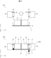
図1は、本実施形態に係る耐力壁構造100の概略構成を示す分解斜視図であり、左側が大壁式の耐力壁パネル1の構成を示し、右側が構造軸材3の構成を示す。図2は、耐力壁パネル1を構造軸材3に取り付ける様子を模式的に示すXZ断面図である。図2の201は、耐力壁パネル1を構造軸材3の柱材20に取り付ける前の状態を示し、図2の202は、耐力壁パネル1を構造軸材3に取り付けた後の状態を示す。
[Embodiment 1]
Fig. 1 is an exploded perspective view showing the schematic configuration of a bearing
図1および図2に示されるように、本実施形態に係る耐力壁構造100は、耐力壁パネル1と、構造軸材3と、を備えている。
As shown in Figures 1 and 2, the bearing
耐力壁パネル1は、大壁方式であり、矩形板状の耐力面材10と、枠材11と、断熱・吸音材14と、を備えている。耐力面材10における構造軸材3側の面に、枠材11は設けられている。耐力面材10の寸法は、例えば、縦2,730mm、横906mm、厚さ9.0mmである。
The load-bearing wall panel 1 is of the large wall type and comprises a rectangular plate-shaped load-
なお、本実施形態において、矩形板状の耐力面材10の短辺方向をX方向とし、長辺方向をY方向とし、X方向およびY方向の両方に垂直な方向をZ方向とする。Z方向は、耐力面材10および断熱・吸音材14の積層方向、または、耐力壁パネル1もしくは耐力面材10の厚さ方向ともいえる。
In this embodiment, the short side direction of the rectangular plate-shaped load-
構造軸材3は、柱材20と、土台21と、梁22とを備えている。具体的には、構造軸材3は、二本の柱材20が土台21に、当該土台21の長辺に対して柱材20の長辺が垂直方向(図1でY方向)になるようにして土台21の両端に固定され、梁22が上記二本の柱材20に、土台21の長辺に対して梁の長辺が平行(図1でX方向)になるようにして固定されて構成されている。
The
図2の201および202に示されるように、大壁方式の耐力壁構造100では、ドリフトピン7(接合金具)によって、構造軸材3に大壁方式の耐力壁パネル1が接合固定される。耐力壁パネル1の耐力面材10には、ドリフトピン7が挿入される通孔5が形成されている。通孔5は、耐力面材10の厚さ方向、すなわちZ方向に形成されている。換言すれば、通孔5は、Z方向に耐力面材10を貫通するように構成されている。
As shown in 201 and 202 in FIG. 2, in a large-wall type load-
また、構造軸材3の柱材20には、孔部6が形成されている。孔部6には、通孔5を通過したドリフトピン7が固定される。このため、図2の202に示されるように、孔部6は、柱材20に対して、耐力面材10と対向する面に設けられている。そして、耐力面材10が柱材20と接合したとき、通孔5は、孔部6と連通する。
In addition, a
ここで、本実施形態に係る耐力壁構造100の製造方法は、通孔5および孔部6にドリフトピン7を挿入することによって、耐力壁パネル1と構造軸材3とを接合固定する工程を有する。より具体的には、当該工程では、ドリフトピン7を、耐力面材10の通孔5から柱材20の孔部6側へ打ち込み、耐力壁パネル1を柱材20に固定する。
The manufacturing method for the load-
このように耐力壁パネル1と構造軸材3とを接合固定するに際し、本実施形態に係る耐力壁構造100は、耐力面材10にドリフトピン7がめり込むのを防止することができるという効果を奏する。以下、図3を参照して、耐力壁構造100の効果について説明する。
When joining and fixing the bearing wall panel 1 and the
図3は、耐力面材10の通孔5および耐力面材10の孔部6、並びにドリフトピン7の構成を示す図である。図3の301は、ドリフトピン7により耐力面材10および柱材20が接合固定された状態を示す断面図である。図3の302は、ドリフトピン7の概略構成を示す側面図である。
Figure 3 is a diagram showing the through
まず、図3の302に示されるように、ドリフトピン7は、先端部7a、胴部7b、首部7c、および頭部7dがこの順に配された円柱構造である。なお、ドリフトピン7の構造は、円柱構造に限定されず、柱状構造であればよい。例えば、ドリフトピン7は、角柱構造であってもよい。
First, as shown in 302 of FIG. 3, the
先端部7aは、先端へ向かいに従い先細りになるテーパー形状である。また、胴部7bは、複数の凹凸が形成された抜止め構造を有する。これにより、耐力面材10および柱材20に対するドリフトピン7の引っ掛かりが強固になる。
The
また、首部7cは、胴部7bよりも大径である。このため、胴部7bと首部7cとの間には、段差が形成される。当該段差部分は、ドリフトピン7の軸周りに円状に形成される。図3の302に示された構成では、当該段差部分は、テーパー部7c1である。テーパー部7c1は、首部7cから胴部7bへ向かうに従い幅狭になるように(直径が小さくなるように)構成されている。
The
また、当該段差部分には、複数の凸凹形状が形成されていてもよい。当該段差部分に複数の凸凹形状を形成することにより、柱材20との摩擦抵抗が増し、より強固に構造軸材3を接合固定することができる。
The step portion may have multiple projections and recesses. By forming multiple projections and recesses in the step portion, the frictional resistance with the
また、頭部7dは、首部7cより大径であり、かつ、平坦な円盤状である。これにより、耐力面材10に対するドリフトピン7のめり込みを防止できる。また、図3の301に示されるように、ドリフトピン7により耐力面材10および柱材20が接合固定された状態では、頭部7dは、通孔5に挿入されていない。
The
また、頭部7dのうち耐力壁パネル1の耐力面材10と接する側の面には、複数の凸凹形状が形成されていてもよい。頭部7dに複数の凸凹形状を形成することにより、耐力壁パネル1の耐力面材10との摩擦抵抗が増し、耐力壁パネル1をより強固に接合固定することができる。
The
通孔5および孔部6内にドリフトピン7が固定されるように、通孔5および孔部6の長さの合計は、ドリフトピン7における先端部7aから首部7cまでの長さ以上であることが好ましい。
In order for the
通孔5は、ドリフトピン7における首部7cの形状に適合するように構成されている。耐力壁構造100では、孔部6に対し胴部7bの抜け止め構造が引っ掛かり、胴部7bより大径である首部7cは柱材20の孔部6に入り込むことなく通孔5にて係止する。そして、頭部7dにて、耐力壁パネル1の耐力面材10を係止することによって、ドリフトピン7は、耐力面材10にめり込むことなく、柱材20との接合が強固となる。そして、柱材20に対し振動が加わった場合においても、ドリフトピン7が耐力面材10及び柱材20から抜け落ちることがない。
The through
ここで、通孔5は、孔部6よりも大径である。このため、耐力壁構造100においては、通孔5と孔部6とが連結するように耐力面材10と柱材20とが接合したとき、通孔5と孔部6との間で、側壁は、互いに面一とならず段差が生じる。換言すれば、通孔5を通して、柱材20における耐力面材10側の面および孔部6の縁部が視認可能となる。それゆえ、ドリフトピン7を打ち込むと、胴部7bと首部7cとの間の段差部分が、柱材20に当接する。首部7cは胴部7bよりも大径であるので、柱材20の孔部6に入り込むことなく、ドリフトピン7の柱材20への移動が係止される。その結果、本実施形態に係る耐力壁構造100によれば、耐力壁パネル1の耐力面材10に対するドリフトピン7のめり込みを防止することができる。
Here, the through
さらに、耐力壁構造100では、耐力面材10とドリフトピン7との接合部のせん断強度に対して、柱材20とドリフトピン7との接合部のせん断強度が勝る。それゆえ、ドリフトピン7は耐力面材10と接する首部7cに対して柱材20と接する胴部7bの径が小さくなることによって、ドリフトピン7の重量を軽量化できるという効果を奏する。
Furthermore, in the load-
ドリフトピン7の寸法は、具体的には、全長52mm、先端部7a:φ10mm径×5mm長、胴部7b:φ12mm径×35mm長、首部7c:φ15mm径×9mm長、頭部7d:φ25mm径×3mm長である寸法;全長52mm、先端部7a:φ10mm径×5mm長、胴部7b:φ12mm径×35mm長、首部7c:φ15mm径×9mm長、頭部7d:φ19mm径×3mm長;全長70mm、先端部7a:φ10mm径×5mm長、胴部7b:φ12mm径×53mm長、首部7c:φ15mm径×9mm長、頭部7d:φ25mm径×3mm長;等が挙げられる。
Specific dimensions of the
(枠材11の構成例)
耐力壁パネル1に設けられた枠材11は、従来公知の構造であれば、任意の構造を採用することができる。図4の401~403は、耐力壁パネルに設けられた枠材の構成例を示す図である。
(Configuration example of frame material 11)
The
図4の401に示された耐力壁パネル1Aでは、枠材は、Y方向に伸びる縦枠材11a~11c、およびX方向に伸びる横枠材11d~11eにより構成されている。縦枠材11a~11c、および横枠材11d~11eは、少なくとも耐力面材10と接する面が互いに面一になるように構成されている。
In the load-
縦枠材11bは、耐力面材10の中央部に取り付けられる。縦枠材11aは、縦枠材11bに対して、耐力面材10の左辺側に取り付けられる。また、縦枠材11cは、縦枠材11bに対して、耐力面材10の右辺側に取り付けられる。
The
横枠材11eは、耐力面材10の中央部に、縦枠材11bと交差するように取り付けられている。また、横枠材11dは、横枠材11eに対して、耐力面材10の上辺側に取り付けられている。また、横枠材11fは、横枠材11eに対して、耐力面材10の下辺側に取り付けられている。
The
また、図4の401に示す枠材では、縦枠材11aおよび11cと、横枠材11dおよび11fとによって、矩形が形成される。そして、縦枠材11bは、当該矩形のX方向に伸びる2辺間をつなぎ、かつ当該矩形の中央部を通過する中枠である。また、横枠材11eは、当該矩形のY方向に伸びる2辺間をつなぎ、かつ当該矩形の中央部を通過する中枠である。
In the frame material shown in FIG. 4 at 401, a rectangle is formed by
また、通孔5は、縦枠材11a~11cおよび横枠材11d~11eの端部を通過し、かつ、耐力面材10の矩形形状を構成する辺に平行な4つの線分により構成された矩形のうち、最も面積が大きな矩形領域の外側に設けられている。通孔5は、耐力面材10において、枠材が構成する前記矩形の外側の領域に設けられている。通孔5は、耐力面材10のY方向に伸びる2つの長辺それぞれに対して、4つ設けられている。
The through
また、矩形状の断熱・吸音材14は、耐力面材10における枠材側の面に設けられている。そして、断熱・吸音材14は、枠材を覆うように設けられていてもよいが、好ましくは、枠材と面一になるように設けられている。図4の401に示された構成では、縦枠材11a~11cおよび横枠材11d~11eによって形成された4つの矩形領域それぞれに断熱・吸音材14が配置されている。そして、断熱・吸音材14は、耐力面材10と反対側の面が、縦枠材11a~11cおよび横枠材11d~11eと面一になっている。
The rectangular heat insulating and
図4の402に示された耐力壁パネル1Bでは、枠材は、縦枠材11b、および横枠材11d・11fにより構成されている。また、矩形状の断熱・吸音材14は、縦枠材11b、および横枠材11d・11fによって形成される枠形状に適合するように構成されている。また、断熱・吸音材14は、耐力面材10と反対側の面が、縦枠材11b、および横枠材11d・11fと面一になっている。そして、断熱・吸音材14は、横枠材11dおよび11fそれぞれの端面と面一になるように構成されている。断熱・吸音材14は、縦枠材11bおよび横枠材11d・11fによって形成される枠形状において、互いに交わる2つの枠線部分を辺とする矩形に適合するように構成されている。
In the load-
また、通孔5は、縦枠材11bおよび横枠材11d・11fの端部を通過し、かつ、耐力面材10の矩形形状を構成する辺に平行な4つの線分により構成された矩形のうち、最も面積が大きな矩形領域の外側に設けられている。具体的には、横枠材11dおよび11fそれぞれの端部を四隅とする矩形領域の外側に形成されている。
The through
図4の403に示された耐力壁パネル1Cでは、枠材は、縦枠材11bおよび横枠材11e・11fにより構成されている。また、矩形状の断熱・吸音材14は、縦枠材11bおよび横枠材11e・11fによって形成される枠形状に適合するように構成されている。また、断熱・吸音材14は、耐力面材10と反対側の面が、縦枠材11bおよび横枠材11e・11fと面一になっている。そして、断熱・吸音材14は、縦枠材11bおよび横枠材11e・11fそれぞれの端面と面一になるように構成されている。断熱・吸音材14は、縦枠材11bおよび横枠材11e・11fによって形成される枠形状において、互いに交わる2つの枠線部分を辺とする矩形に適合するように構成されている。
In the load-
また、通孔5は、縦枠材11bおよび横枠材11e・11fの端部を通過し、かつ、耐力面材10の矩形形状を構成する辺に平行な4つの線分により構成された矩形のうち、最も面積が大きな矩形領域の外側に設けられている。具体的には、横枠材11dおよび11fそれぞれの端部を四隅としない矩形領域の外側に形成されている。
The through
なお、耐力壁パネルの強度を十分に確保する観点から、耐力面材10に設けられる枠材は、少なくとも縦枠材11bを備えていることが好ましい。縦枠材11bは、耐力面材10の略中央部に取り付けられるので、耐力壁パネルの強度を確保する上で重要な役割があるためである。
In order to ensure sufficient strength of the load-bearing wall panel, it is preferable that the frame material provided on the load-
(ドリフトピン7の構成例)
本実施形態に係る耐力壁構造100において、ドリフトピン7の胴部7bの構造は、複数の凹凸が形成された抜止め構造を有していれば、特に限定されない。図5の501~505は、胴部7bの構成例を模式的に示す側面図である。
(Example of the configuration of the drift pin 7)
In the bearing
図5の501に示されたドリフトピン7Aは、矩形凸部が互いに隣接して構成された鑢構造の胴部7b1を有する。
The
また、図5の502に示されたドリフトピン7Bの胴部7b2は、ドリフトピン7の円周方向および軸方向に複数のギザ部が隣接して整列した構造となっている。当該ギザ部は、ドリフトピン7の半径方向の外側に尖った鋭角部、および先端部7aへ向かうテーパー面を有する。
The body 7b2 of the
図5の503に示されたドリフトピン7Cの胴部7b3は、外側に尖った凸条が連続して螺旋状に形成されたねじ状構造を有する。図5の504に示されたドリフトピン7Dの胴部7b4は、ドリフトピン7の円周方向および軸方向において、上記ギザ部が互いに離間して整列した構造となっている。図5の505に示されたドリフトピン7Eの胴部7b5は、上記凸条が断続的に螺旋状に形成されたねじ構造である。
The body 7b3 of the
図5の501~505に示された構成であっても、耐力面材に対してドリフトピン7A~7Eを抜止めすることが可能である。 Even with the configuration shown in 501 to 505 in Figure 5, it is possible to prevent the drift pins 7A to 7E from being pulled out of the load-bearing surface material.
(耐力壁構造100の製造方法)
本実施形態に係る耐力壁構造100の製造方法は、上述した、通孔5および孔部6にドリフトピン7を挿入することによって、耐力壁パネル1と構造軸材3とを接合固定する工程(以下、接合工程と記す)を含んでいればよい。
(Method of manufacturing the load-bearing wall structure 100)
The manufacturing method for the load-
当該製造方法は、前記接合工程の他に、耐力壁パネル1に通孔5を形成する通孔形成工程、および構造軸材3に孔部6を形成する孔部形成工程の少なくとも1つの構成を含んでいてもよい。この場合、通孔形成工程および孔部形成工程は、耐力壁構造100の構成部材を製造する工場にて実施してもよいし、耐力壁構造100を組み立てる施工現場にて実施してもよい。より好ましくは、通孔形成工程および孔部形成工程を前記工場にて実施し、前記接合工程を前記施工現場にて実施する。これにより、施工現場での工数を削減でき、生産性を向上できる。
In addition to the joining process, the manufacturing method may include at least one of a through-hole forming process for forming a through
〔実施形態2〕
本発明の他の実施形態について、以下に説明する。なお、説明の便宜上、上記実施形態にて説明した部材と同じ機能を有する部材については、同じ符号を付記し、その説明を繰り返さない。
[Embodiment 2]
Other embodiments of the present invention will be described below. For ease of explanation, the same reference numerals are given to members having the same functions as those described in the above embodiment, and the description thereof will not be repeated.
図6は、本実施形態に係る耐力壁構造100Aを組み立てる様子を模式的示すXZ断面図である。図6の601は、真壁式の耐力壁パネル2を柱材20に取り付ける前の状態を示し、図6の602は、耐力壁パネル2を柱材20に取り付けた後の状態を示す。
Figure 6 is an XZ cross-sectional view showing the assembly of the bearing
図6の601および602に示されるように、本実施形態に係る耐力壁構造100Aは、耐力壁パネル2が真壁式である点、および柱材20に受け材23が設けられている点が実施形態1と異なる。
As shown in 601 and 602 in FIG. 6, the load-
真壁式の耐力壁パネル2は、柱材20に取り付けられたとき、耐力面材10の背面が柱材20の背面と略面一になるように構成されている。また、枠材11は、図1の101に示された構成と同様である。すなわち、耐力面材10における柱材20側の辺部には、枠材11が設けられていない。このため、耐力壁パネル2が柱材20に取り付けられたとき、断熱・吸音材14と柱材20との間に隙間が生じる。受け材23は、当該隙間に設けられており、耐力壁パネル2を受けるための部材である。
When the solid wall type load-
受け材23は、留付材24によって、柱材20に固定されている。留付材24は、例えば、釘、ビス、ネジが挙げられる。
The
耐力壁パネル2の耐力面材10には、ドリフトピン7が挿入される通孔5が形成されている。通孔5は、耐力面材10の厚さ方向、すなわちZ方向に形成されている。
The bearing
また、孔部6は、受け材23に形成されている。孔部6は、受け材23に対して、耐力面材10と対向する面に設けられている。そして、耐力面材10が柱材20と接合したとき、通孔5は、孔部6と連通する。
The
耐力壁構造100Aの構成であっても、耐力壁パネル1と構造軸材3とを接合固定するに際し、耐力面材10にドリフトピン7がめり込むのを防止することができるという効果を奏する。
Even with the configuration of the load-
〔実施形態3〕
本発明のさらに他の実施形態について、以下に説明する。なお、説明の便宜上、上記実施形態にて説明した部材と同じ機能を有する部材については、同じ符号を付記し、その説明を繰り返さない。
[Embodiment 3]
Further, for the sake of convenience, the same reference numerals are given to the members having the same functions as those described in the above embodiment, and the description thereof will not be repeated.
図7は、本実施形態に係る耐力壁構造100Bを組み立てる様子を模式的示すXZ断面図である。図7の701は、真壁式の耐力壁パネル2Aを柱材20に取り付ける前の状態を示し、図7の702は、耐力壁パネル2Aを柱材20に取り付けた後の状態を示す。
Figure 7 is an XZ cross-sectional view showing the assembly of the bearing
図7の701および702に示されるように、本実施形態に係る耐力壁構造100Bは、耐力壁パネル2Aの構造が実施形態1および2と異なる。
As shown in 701 and 702 in FIG. 7, the load-
耐力壁パネル2Aは、柱材20に取り付けられたとき、耐力面材10の背面が柱材20の背面と略面一になるように構成されている。枠材11は、図1の101に示された構成と異なる。耐力面材10における柱材20側の辺部には、枠材11が設けられている。このため、耐力壁パネル2が柱材20に取り付けられたとき、断熱・吸音材14と柱材20との間に枠材11が配置される。
The load-
このため、孔部6は、耐力面材10と対向する側面に設けられている。孔部6は、X方向に伸びて形成されている。そして、通孔5は、枠材11に設けられている。具体的には、耐力面材10における柱材20側の辺部に設けられた枠材11に、通孔5は、X方向に伸びて形成されている。耐力面材10が柱材20と接合したとき、通孔5は、孔部6と連通する。
For this reason, the
耐力壁構造100Bの構成であっても、耐力壁パネル1と構造軸材3とを接合固定するに際し、耐力面材10にドリフトピン7がめり込むのを防止することができるという効果を奏する。
Even with the configuration of the load-
本発明は上述した各実施形態に限定されるものではなく、請求項に示した範囲で種々の変更が可能であり、異なる実施形態にそれぞれ開示された技術的手段を適宜組み合わせて得られる実施形態についても本発明の技術的範囲に含まれる。 The present invention is not limited to the above-described embodiments, and various modifications are possible within the scope of the claims. The technical scope of the present invention also includes embodiments obtained by appropriately combining the technical means disclosed in different embodiments.
(まとめ)
本発明の態様1に係る耐力壁構造100は、木造軸組工法における耐力壁構造100であって、構造軸材3と、耐力壁パネル1と、前記構造軸材3と前記耐力壁パネル1とを接合固定する接合金具(ドリフトピン7)と、を備え、前記接合金具は、先端部7a、抜止め構造を有する胴部7b、前記胴部7bよりも大径である首部7c、および頭部7dがこの順に配された柱状構造であり、前記耐力壁パネル1は、前記接合金具が挿入される通孔5を有し、前記構造軸材3は、前記接合金具が固定される孔部6を有し、前記通孔5は、前記孔部6よりも大径である構成である。
(summary)
The load-
本発明の態様1に係る耐力壁構造100は、態様1において、前記耐力壁パネル1は、耐力面材10と、前記耐力面材10上に設けられた枠材11と、を備え、前記耐力面材10における前記枠材11側の面に、断熱材および/または吸音材(断熱・吸音材14)が配設されている構成である。
In the load-
本発明の態様3に係る耐力壁構造100は、態様2において、前記通孔5は、前記耐力面材10において、当該耐力面材10の厚さ方向(Z方向)に形成されている構成である。
The bearing
本発明の態様4に係る耐力壁構造100は、態様3において、前記耐力面材10の面上において、前記通孔5は、前記枠材11よりも外側の領域に配置されている構成である。
The load-
本発明の態様5に係る耐力壁パネル用接合金具(ドリフトピン7)は、構造軸材3と耐力壁パネル1とを接合固定する耐力壁パネル用接合金具であって、先端部7a、胴部7b、首部7c、および頭部7dがこの順に配された柱状構造であり、前記先端部7aは、テーパー形状であり、前記胴部7bは、複数の凸凹が形成された抜止め構造を有し、前記首部7cは、前記胴部7bよりも大径であり、前記頭部7dは、前記首部7cよりも大径であり、かつ、平板形状であり、前記先端部7a、前記胴部7b、および前記首部7cは、前記耐力壁パネル1に設けられた通孔5に挿入される構造であり、前記頭部7dは、前記通孔5よりも大径である構成である。
The joint fitting for a load-bearing wall panel (drift pin 7) according to
本発明の態様6に係る耐力壁パネル用接合金具(ドリフトピン7)は、態様5において、前記胴部7bと前記首部7cとの間には、前記首部7cから前記胴部7bへ向かうに従い幅狭になるように構成されたテーパー部7c1が設けられている構成である。
The joint hardware for load-bearing wall panels (drift pin 7) according to
本発明の態様7に係る耐力壁パネル1は、先端部7a、抜止め構造を有する胴部7b、前記胴部7bよりも大径である首部7c、および頭部7dがこの順に配された柱状構造である接合金具(ドリフトピン7)によって構造軸材3に接合固定される耐力壁パネル1であって、前記接合金具が挿入される通孔5を有し、前記通孔5は、前記構造軸材3に設けられた、前記接合金具が固定される孔部6よりも大径である構成である。
The load-bearing wall panel 1 according to
本発明の態様8に係る耐力壁構造100の製造方法は、接合金具(ドリフトピン7)によって構造軸材3と耐力壁パネル1とを接合固定する、木造軸組工法における耐力壁構造100の製造方法であって、前記接合金具は、先端部7a、抜止め構造を有する胴部7b、前記胴部7bよりも大径である首部7c、および頭部7dがこの順に配された柱状構造であり、前記耐力壁パネル1は、前記接合金具が挿入される通孔5を有し、前記構造軸材3は、前記接合金具が固定される孔部6を有するものであり、前記通孔5は、前記孔部6よりも大径であり、前記通孔5および前記孔部6に前記接合金具を挿入することによって、構造軸材3と耐力壁パネル1とを接合固定する工程を有する。
The manufacturing method of the bearing
本発明の一態様に係る耐力壁構造およびその製造方法は、木造建築物の建築、即ち、木造建築物を施工する木造軸組工法において好適に用いられる。 The bearing wall structure and manufacturing method thereof according to one embodiment of the present invention are suitable for use in the construction of wooden buildings, i.e., in the wooden frame construction method for constructing wooden buildings.
1、1A、1B、1C、2、2A 耐力壁パネル
3 構造軸材
5 通孔
6 孔部
7、7A、7B、7C、7D、7E ドリフトピン(接合金具)
7a 先端部
7b、7b1、7b2、7b3、7b4、7b5 胴部
7c 首部
7c1 テーパー部
7d 頭部
10 耐力面材
11、11a、11b、11c、11d、11e、11f 枠材
14 断熱・吸音材
20 柱材(構造軸材)
21 土台(構造軸材)
22 梁(構造軸材)
23 受け材(構造軸材)
100、100A、100B 耐力壁構造
1, 1A, 1B, 1C, 2, 2A Load-
21 Foundation (structural shaft material)
22 Beam (structural shaft material)
23 Support material (structural shaft material)
100, 100A, 100B load-bearing wall structure
Claims (10)
構造軸材と、
耐力壁パネルと、
前記構造軸材と前記耐力壁パネルとを接合固定する接合金具と、を備え、
前記接合金具は、先端部、抜止め構造を有する胴部、前記胴部よりも大径である首部、および頭部がこの順に配された柱状構造であり、
前記耐力壁パネルは、前記接合金具が挿入される通孔を有し、
前記構造軸材は、前記接合金具が固定される孔部を有し、
前記通孔は、前記孔部よりも大径であり、
前記接合金具がドリフトピンである、耐力壁構造。 A load-bearing wall structure in a wooden frame construction method,
A structural shaft material;
Load-bearing wall panels;
and a joint metal fitting for joining and fixing the structural shaft member and the load-bearing wall panel,
The metal joint has a columnar structure including a tip portion, a body portion having a pull-out prevention structure, a neck portion having a larger diameter than the body portion, and a head portion, which are arranged in this order,
The bearing wall panel has a through hole into which the joint metal fitting is inserted,
The structural shaft member has a hole to which the metal joint is fixed,
The through hole has a larger diameter than the hole portion,
A load-bearing wall structure , wherein the joint fitting is a drift pin .
構造軸材と、A structural shaft material;
耐力壁パネルと、Load-bearing wall panels;
前記構造軸材と前記耐力壁パネルとを接合固定する接合金具と、を備え、and a joint metal fitting for joining and fixing the structural shaft member and the load-bearing wall panel,
前記接合金具は、先端部、抜止め構造を有する胴部、前記胴部よりも大径である首部、および頭部がこの順に配された柱状構造であり、The metal joint has a columnar structure including a tip portion, a body portion having a pull-out prevention structure, a neck portion having a larger diameter than the body portion, and a head portion, which are arranged in this order,
前記耐力壁パネルは、前記接合金具が挿入される通孔を有し、The bearing wall panel has a through hole into which the joint metal fitting is inserted,
前記構造軸材は、前記接合金具が固定される孔部を有し、The structural shaft member has a hole to which the metal joint is fixed,
前記通孔は、前記孔部よりも大径であり、The through hole has a larger diameter than the hole portion,
前記接合金具について、Regarding the above-mentioned metal fittings,
前記胴部と前記首部との間には、前記首部から前記胴部へ向かうに従い幅狭になるように構成されたテーパー部が設けられている、耐力壁構造。A load-bearing wall structure, comprising a tapered portion between the body and the neck, the tapered portion being configured to narrow from the neck toward the body.
前記耐力面材における前記枠材側の面に、断熱材および/または吸音材が配設されている、請求項1または2に記載の耐力壁構造。 The load-bearing wall panel comprises a load-bearing surface material and a frame material provided on the load-bearing surface material,
3. The load-bearing wall structure according to claim 1, wherein a heat insulating material and/or a sound absorbing material is arranged on a surface of the load-bearing face material facing the frame member.
先端部、胴部、首部、および頭部がこの順に配された柱状構造であり、
前記先端部は、テーパー形状であり、
前記胴部は、複数の凸凹が形成された抜止め構造を有し、
前記首部は、前記胴部よりも大径であり、
前記頭部は、前記首部よりも大径であり、かつ、平板形状であり、
前記先端部、前記胴部、および前記首部は、前記耐力壁パネルに設けられた通孔に挿入される構造であり、前記頭部は、前記通孔よりも大径である、耐力壁パネル用接合金具。 A joint fitting for a bearing wall panel , which is a drift pin that joins and fixes a structural shaft member and a bearing wall panel,
A columnar structure having a tip, a body, a neck, and a head arranged in this order;
The tip portion is tapered.
The body portion has a pull-out prevention structure formed with a plurality of projections and recesses,
The neck portion has a larger diameter than the body portion,
The head portion has a larger diameter than the neck portion and has a flat plate shape.
A fastening fitting for a load-bearing wall panel, wherein the tip portion, the body portion, and the neck portion are configured to be inserted into a through hole provided in the load-bearing wall panel, and the head portion has a larger diameter than the through hole.
先端部、胴部、首部、および頭部がこの順に配された柱状構造であり、A columnar structure having a tip, a body, a neck, and a head arranged in this order;
前記先端部は、テーパー形状であり、The tip portion is tapered.
前記胴部は、複数の凸凹が形成された抜止め構造を有し、The body portion has a pull-out prevention structure formed with a plurality of projections and recesses,
前記首部は、前記胴部よりも大径であり、The neck portion has a larger diameter than the body portion,
前記頭部は、前記首部よりも大径であり、かつ、平板形状であり、The head portion has a larger diameter than the neck portion and has a flat plate shape.
前記先端部、前記胴部、および前記首部は、前記耐力壁パネルに設けられた通孔に挿入される構造であり、前記頭部は、前記通孔よりも大径であり、The tip portion, the body portion, and the neck portion are configured to be inserted into a through hole provided in the load-bearing wall panel, and the head portion has a larger diameter than the through hole;
前記胴部と前記首部との間には、前記首部から前記胴部へ向かうに従い幅狭になるように構成されたテーパー部が設けられている、耐力壁パネル用接合金具。A joint for a load-bearing wall panel, wherein a tapered portion is provided between the body portion and the neck portion so that the width narrows as the member moves from the neck portion to the body portion.
前記接合金具は、先端部、抜止め構造を有する胴部、前記胴部よりも大径である首部、および頭部がこの順に配された柱状構造を有するドリフトピンであり、
前記耐力壁パネルは、前記接合金具が挿入される通孔を有し、
前記構造軸材は、前記接合金具が固定される孔部を有するものであり、
前記通孔は、前記孔部よりも大径であり、
前記通孔および前記孔部に前記接合金具を挿入することによって、構造軸材と耐力壁パネルとを接合固定する工程を有する、耐力壁構造の製造方法。 A manufacturing method for a load-bearing wall structure in a wooden frame construction method, in which a structural member and a load-bearing wall panel are joined and fixed by a joint metal fitting,
The connecting metal fitting is a drift pin having a columnar structure in which a tip portion, a body portion having a pull-out prevention structure, a neck portion having a larger diameter than the body portion, and a head portion are arranged in this order,
The bearing wall panel has a through hole into which the joint metal fitting is inserted,
The structural shaft member has a hole to which the metal joint is fixed,
The through hole has a larger diameter than the hole portion,
A manufacturing method for a load-bearing wall structure, comprising a step of joining and fixing a structural axis member and a load-bearing wall panel by inserting the fastening metal fittings into the through holes and the hole portions.
前記接合金具は、先端部、抜止め構造を有する胴部、前記胴部よりも大径である首部、および頭部がこの順に配された柱状構造であって、前記胴部と前記首部との間には、前記首部から前記胴部へ向かうに従い幅狭になるように構成されたテーパー部が設けられており、The connecting fitting has a columnar structure including a tip portion, a body portion having a pull-out prevention structure, a neck portion having a larger diameter than the body portion, and a head portion, which are arranged in this order, and a tapered portion is provided between the body portion and the neck portion so that the width of the tapered portion narrows from the neck portion toward the body portion,
前記耐力壁パネルは、前記接合金具が挿入される通孔を有し、The bearing wall panel has a through hole into which the joint metal fitting is inserted,
前記構造軸材は、前記接合金具が固定される孔部を有するものであり、The structural shaft member has a hole to which the metal joint is fixed,
前記通孔は、前記孔部よりも大径であり、The through hole has a larger diameter than the hole portion,
前記通孔および前記孔部に前記接合金具を挿入することによって、構造軸材と耐力壁パネルとを接合固定する工程を有する、耐力壁構造の製造方法。A manufacturing method for a load-bearing wall structure, comprising a step of joining and fixing a structural axis member and a load-bearing wall panel by inserting the fastening metal fittings into the through holes and the hole portions.
Priority Applications (1)
| Application Number | Priority Date | Filing Date | Title |
|---|---|---|---|
| JP2020142081A JP7561543B2 (en) | 2020-08-25 | 2020-08-25 | Bearing wall structure and its use |
Applications Claiming Priority (1)
| Application Number | Priority Date | Filing Date | Title |
|---|---|---|---|
| JP2020142081A JP7561543B2 (en) | 2020-08-25 | 2020-08-25 | Bearing wall structure and its use |
Publications (2)
| Publication Number | Publication Date |
|---|---|
| JP2022037772A JP2022037772A (en) | 2022-03-09 |
| JP7561543B2 true JP7561543B2 (en) | 2024-10-04 |
Family
ID=80494823
Family Applications (1)
| Application Number | Title | Priority Date | Filing Date |
|---|---|---|---|
| JP2020142081A Active JP7561543B2 (en) | 2020-08-25 | 2020-08-25 | Bearing wall structure and its use |
Country Status (1)
| Country | Link |
|---|---|
| JP (1) | JP7561543B2 (en) |
Citations (2)
| Publication number | Priority date | Publication date | Assignee | Title |
|---|---|---|---|---|
| JP2002088949A (en) | 2000-09-18 | 2002-03-27 | Ibiden Co Ltd | Method of executing wall panel, wall panel and drift pin |
| JP2006161485A (en) | 2004-12-09 | 2006-06-22 | Nittetsu Steel Sheet Corp | Panel fixture and panel mounting structure |
Family Cites Families (1)
| Publication number | Priority date | Publication date | Assignee | Title |
|---|---|---|---|---|
| JPH11124927A (en) * | 1997-10-22 | 1999-05-11 | Mitsubishi Chemical Corp | Insulated wall and method of construction |
-
2020
- 2020-08-25 JP JP2020142081A patent/JP7561543B2/en active Active
Patent Citations (2)
| Publication number | Priority date | Publication date | Assignee | Title |
|---|---|---|---|---|
| JP2002088949A (en) | 2000-09-18 | 2002-03-27 | Ibiden Co Ltd | Method of executing wall panel, wall panel and drift pin |
| JP2006161485A (en) | 2004-12-09 | 2006-06-22 | Nittetsu Steel Sheet Corp | Panel fixture and panel mounting structure |
Also Published As
| Publication number | Publication date |
|---|---|
| JP2022037772A (en) | 2022-03-09 |
Similar Documents
| Publication | Publication Date | Title |
|---|---|---|
| CN103306365B (en) | Architectural Construction body made by wood | |
| JP7649899B2 (en) | Wall structure and construction method of wall structure | |
| JP2019196634A (en) | Reinforcement member for wooden frame | |
| JP2018162602A (en) | Joint metal and joint structure of wall | |
| WO2020158525A1 (en) | Installation construction method for wall panels | |
| JP7561543B2 (en) | Bearing wall structure and its use | |
| JP7523764B2 (en) | Load-bearing wall structure | |
| JP6892991B2 (en) | Joint structure of wall member and foundation | |
| JP7824790B2 (en) | Joint structure | |
| JPH11131590A (en) | Bracing fixture and bracing method | |
| JP4473771B2 (en) | Exterior wall structure | |
| JP7163148B2 (en) | damping device | |
| JPH10266363A (en) | Structure construction method by two-member jointing metal fixture | |
| JP4296080B2 (en) | Wall member | |
| JP4654674B2 (en) | How to install seismic reinforcement brackets for wooden buildings | |
| JP7671103B1 (en) | Joining materials | |
| JP3069945U (en) | Seismic reinforcement hardware and seismic reinforcement structure for wooden buildings | |
| JP2010077645A (en) | Joint structure in wooden building | |
| JP3708712B2 (en) | Slab panel construction method | |
| JP4764908B2 (en) | Joint structure of wood structure members | |
| JP2019214923A (en) | Bearing wall and its construction method | |
| JP2019214878A (en) | Bearing wall and construction method thereof | |
| JP2001107456A (en) | Column base structure in wooden rigid frame | |
| JP2000220303A (en) | Earthquake resistant reinforcing structure of building | |
| JP2006307568A (en) | Beam-column connection structure and beam-column connection method |
Legal Events
| Date | Code | Title | Description |
|---|---|---|---|
| A621 | Written request for application examination |
Free format text: JAPANESE INTERMEDIATE CODE: A621 Effective date: 20230714 |
|
| A977 | Report on retrieval |
Free format text: JAPANESE INTERMEDIATE CODE: A971007 Effective date: 20240319 |
|
| A131 | Notification of reasons for refusal |
Free format text: JAPANESE INTERMEDIATE CODE: A131 Effective date: 20240326 |
|
| A601 | Written request for extension of time |
Free format text: JAPANESE INTERMEDIATE CODE: A601 Effective date: 20240515 |
|
| A521 | Request for written amendment filed |
Free format text: JAPANESE INTERMEDIATE CODE: A523 Effective date: 20240619 |
|
| TRDD | Decision of grant or rejection written | ||
| A01 | Written decision to grant a patent or to grant a registration (utility model) |
Free format text: JAPANESE INTERMEDIATE CODE: A01 Effective date: 20240903 |
|
| A61 | First payment of annual fees (during grant procedure) |
Free format text: JAPANESE INTERMEDIATE CODE: A61 Effective date: 20240924 |
|
| R150 | Certificate of patent or registration of utility model |
Ref document number: 7561543 Country of ref document: JP Free format text: JAPANESE INTERMEDIATE CODE: R150 |