JP7561548B2 - Water discharge device and water discharge system - Google Patents
Water discharge device and water discharge system Download PDFInfo
- Publication number
- JP7561548B2 JP7561548B2 JP2020151556A JP2020151556A JP7561548B2 JP 7561548 B2 JP7561548 B2 JP 7561548B2 JP 2020151556 A JP2020151556 A JP 2020151556A JP 2020151556 A JP2020151556 A JP 2020151556A JP 7561548 B2 JP7561548 B2 JP 7561548B2
- Authority
- JP
- Japan
- Prior art keywords
- jet
- flow
- water
- film
- water discharge
- Prior art date
- Legal status (The legal status is an assumption and is not a legal conclusion. Google has not performed a legal analysis and makes no representation as to the accuracy of the status listed.)
- Active
Links
Images


Landscapes
- Domestic Plumbing Installations (AREA)
- Bathtubs, Showers, And Their Attachments (AREA)
Description
本開示は、吐水装置および吐水システムに関する。 This disclosure relates to a water discharge device and a water discharge system.
入浴者に対するマッサージ等を目的として、水流を吐水する吐水装置が知られている。従来では、浴槽内の水を取り込んで浴槽に向けて吐水する吐水装置が提案されている(例えば特許文献1)。 Water discharge devices that discharge a water flow for the purpose of massaging the bather or the like are known. Conventionally, water discharge devices have been proposed that take in water from within a bathtub and discharge it toward the bathtub (for example, Patent Document 1).
本開示はこうした状況においてなされたものであり、そのある態様の例示的な目的のひとつは、商品価値を高めた吐水装置を提供することにある。 This disclosure has been made in this context, and one exemplary objective of one embodiment thereof is to provide a water discharge device with increased commercial value.
上記課題を解決するために、本開示のある態様の吐水装置は、噴流を吐水する噴流吐水部と、流れ方向に直交する断面において有端膜状をなし、噴流の下方を通る膜状流を吐水する膜状流吐水部と、を備える。 To solve the above problem, a water discharge device according to one embodiment of the present disclosure includes a jet water discharge section that discharges a jet of water, and a film-like flow water discharge section that discharges a film-like flow that has an end film shape in a cross section perpendicular to the flow direction and passes below the jet.
本開示の別の態様も吐水装置である。この装置は、噴流を吐水する噴流吐水部と、流れ方向に直交する断面において有端膜状をなす膜状流を吐水する膜状流吐水部と、を備える。正面視において、噴流の吐水範囲と膜状流の吐水範囲とは重ならない。 Another aspect of the present disclosure is a water discharge device. This device includes a jet water discharge section that discharges a jet of water, and a film-like flow water discharge section that discharges a film-like flow that has an end-film shape in a cross section perpendicular to the flow direction. When viewed from the front, the water discharge range of the jet and the water discharge range of the film-like flow do not overlap.
本開示のさらに別の態様は、吐水システムである。この吐水システムは、槽体と、槽体内に吐水する上述のいずれかに記載の吐水装置と、を備える。 Yet another aspect of the present disclosure is a water discharge system. This water discharge system includes a tank body and any of the water discharge devices described above that discharge water into the tank body.
以下、図面を参照しながら実施の形態を説明する。各図面に示される同一または同等の構成要素、部材、処理には、同一の符号を付するものとし、適宜重複した説明は省略する。 The following describes the embodiments with reference to the drawings. The same or equivalent components, parts, and processes shown in each drawing are given the same reference numerals, and redundant descriptions will be omitted as appropriate.
(第1の実施の形態)
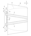
図1、図2を参照する。図1は吐水装置10の模式的な側面図でもある。図2は吐水装置10の模式的な正面図でもある。吐水システム18は、衛生設備12に用いられる。本実施の形態では、衛生設備12は浴室設備である。
First Embodiment
Please refer to Figures 1 and 2. Figure 1 is also a schematic side view of the
吐水システム18は、吐水装置10と、吐水装置10から吐水された水を受けることが可能な槽体20と、槽体20から吐水装置10に水を供給する給水路22と、給水路22の途中に設けられる弁装置24およびポンプ26と、弁装置24およびポンプ26を制御する制御装置28と、を備える。
The
以降、説明の便宜上、吐水装置10の吐水方向に沿った水平方向を前後方向X、前後方向Xに直交する水平方向を左右方向Y、前後方向Xおよび左右方向Yに直交する方向を上下方向Zという。吐水孔38,40側から吐水装置10を前後方向Xに見て、手前側(すなわち吐水孔38,40側)を前側、奥側を後ろ側という。このような方向の表記は吐水装置10の使用姿勢を制限するものではなく、吐水装置10は用途に応じて任意の姿勢で使用されうる。
Hereinafter, for ease of explanation, the horizontal direction along the water discharge direction of the
槽体20は、浴室設備の浴槽である。吐水装置10には、槽体20内の水(不図示)が給水路22を介して供給される。
The
給水路22は、弁装置24より上流側に設けられる上流側水路22aと、弁装置24より下流側に設けられる第1下流側水路22bおよび第2下流側水路22cと、を含む。上流側水路22aの途中には、ポンプ26が設けられる。第1下流側水路22bは、吐水装置10の噴流吐水部50(後述)に水を供給するための水路であり、上流側は弁装置24に連通し、下流側は噴流吐水部50に連通する。第2下流側水路22cは、膜状流吐水部52(後述)に水を供給するための水路であり、上流側は弁装置24に連通し、下流側は膜状流吐水部52に連通する。
The
弁装置24は、第1下流側水路22bおよび第2下流側水路22cのそれぞれと上流側水路22aとの連通の有無を切り替え可能である。弁装置24は、例えば、多方弁等の切替弁や複数の開閉弁を用いて構成される。
The
弁装置24は、制御装置28による制御または手動操作を通じて、第1下流側水路22bおよび第2下流側水路22cの両方と上流側水路22aとを連通する。このとき、ポンプ26によって槽体20内の水を吸引して圧送することで、噴流吐水部50および膜状流吐水部52に水が供給される。これにより、噴流吐水部50から噴流F1が吐水されるとともに、膜状流吐水部52から膜状流F2が吐水される。
The
吐水装置10は、筐体32と、筐体32の内部に形成される噴流吐水部50および膜状流吐水部52と、を備える。筐体32は、衛生設備12のベース30に固定される。本実施の形態では、槽体20の上面開口部の周縁部に設けられる槽体20のフランジ部がベース30を構成する。筐体32は、不図示の固定構造、例えばねじ構造や爪と爪受け等を用いてベース30に固定される。
The
噴流吐水部50は、第1下流側水路22bと連通する2つの噴流水路34と、2つの噴流水路34の下流側に設けられる噴流吐水孔38と、を含む。噴流水路34および噴流吐水孔38の数は特に限定されず、1つであっても、3つ以上であってもよい。
The jet
膜状流吐水部52は、第2下流側水路22cと連通する膜状流水路36と、膜状流水路36の下流側に設けられる膜状流吐水孔40と、を含む。膜状流水路36の数は特に限定されず、2つ以上であってもよい。
The film-like
本実施形態では、噴流水路34および膜状流水路36には、鉛直下方から水が供給される。
In this embodiment, water is supplied to the
噴流吐水部50の2つの噴流吐水孔38は、筐体32の前面部に開口する。噴流吐水孔38は、正面視において(すなわち前後方向Xに前側から見て)、左右方向Xを長手方向とし、上下方向Zを短手方向とする長方形状である。2つの噴流吐水孔38は、左右方向Yに間隔をあけて設けられる。
The two jet
膜状流吐水部52の膜状流吐水孔40は、筐体32の前面部に開口する。膜状流吐水孔40は、左右方向Xを長手方向とし、上下方向Zを短手方向とする長方形状である。すなわち、膜状流吐水孔40は、左右方向Yを長手方向とするスリット状に形成される。
The film-like
膜状流吐水孔40は、2つの噴流吐水孔38よりも下方に設けられる。2つの噴流吐水孔38はそれぞれ、少なくとも一部が膜状流吐水孔40と上下に重なる位置に設けられる。この例では、2つの噴流吐水孔38はそれぞれ、その全体が膜状流吐水孔40と上下に重なる位置に設けられる。言い換えると、2つの噴流吐水孔38はそれぞれ、膜状流吐水孔40の設けられる左右方向Yでの範囲Saの内側に収まる位置に設けられる。
The film-like flow
図1、図3、図4を参照する。噴流吐水部50は、第1下流側水路22bから噴流水路34に供給される水を、2つの噴流吐水孔38のそれぞれから噴流F1として吐水する。噴流吐水部50は、流れ方向や流量が時間的に一定となるように噴流F1を吐水する。ここでは噴流吐水部50は、ユーザの肩に当たるように噴流F1を吐水する。各図には、噴流F1の吐水範囲が示される。2つの噴流吐水孔38から吐水される噴流F1は、前側に向かうほど互いに近づいている。
See Figures 1, 3, and 4. The jet
膜状流吐水部52は、第2下流側水路22cから膜状流水路36に供給される水を、膜状流吐水孔40から、有端膜状(後述)をなす膜状流F2として吐水する。膜状流吐水部52は、流量が時間的に一定となるように膜状流F2を吐水する。膜状流吐水部52は、噴流F1の下方を通るように膜状流F2を吐水する。ここでは膜状流吐水部52は、噴流よりも下方にて肩に当たるように膜状流F2を吐水する。各図には、膜状流F2の吐水範囲が示される。
The film-like
図3のハッチングは、膜状流水路36を飛び出るときの流れ方向に直交する膜状流F2の断面を示す。「有端膜状」とは、流れ方向に直交する断面において、両端部60a、60bが離れた箇所に設けられる膜状を意味する。膜状流F2は、この断面において、非環状をなすともいえる。この条件は、膜状流水路36を飛び出るときの流れ方向に直交する断面において、少なくとも満たされていればよい。本実施の形態の膜状流F2は、このような断面において、直線状を描く有端膜状をなす。膜状流F2は、円弧状等の曲線状でもよいし、その具体的な形状は特に限られない。
The hatching in FIG. 3 indicates a cross section of the film-like flow F2 perpendicular to the flow direction when it leaves the film-
膜状流F2は、流れ方向に直交する断面において、噴流F1よりも左右方向Xに長い、すなわち幅広である。この条件は、膜状流水路36および噴流水路34を飛び出るときの流れ方向に直交する断面において少なくとも満たされていればよい。
The film-like flow F2 is longer, i.e., wider, in the left-right direction X than the jet flow F1 in a cross section perpendicular to the flow direction. This condition needs to be satisfied at least in a cross section perpendicular to the flow direction when the film-like
噴流F1および膜状流F2はいずれも、側面視において(すなわち左右方向Yに見て)放物線状をなすように吐水される。この例において噴流F1は、側面視において、膜状流F2が描く放物線より緩やかな放物線状をなすように吐水される。この例において噴流F1は、側面視において、噴流F1の上方のみを通るように膜状流吐水部52から吐水される。
Both the jet F1 and the film-like flow F2 are discharged so as to form a parabola in side view (i.e., when viewed in the left-right direction Y). In this example, the jet F1 is discharged so as to form a parabola that is gentler than the parabola drawn by the film-like flow F2 in side view. In this example, the jet F1 is discharged from the film-like
以上が吐水システム18の基本構成である。続いて、その効果を説明する。
The above is the basic configuration of the
噴流だけでは肩全体に広がらないため温浴効果が乏しく、膜状流だけでは刺激感が弱いためマッサージ効果が乏しい。これに対し本実施の形態によれば、勢いが強い噴流F1と、幅広である膜状流F2とを同時にユーザに浴びせることができる。これにより、刺激感を与えつつ、広い範囲を温めることができる。例えば、噴流F1を首に当てて首をマッサージしつつ、膜状流F2を肩に当てて肩を広い範囲で温めることができる。つまり、吐水システム18の商品価値が高まる。
A jet flow alone does not spread over the entire shoulder, so the bath effect is poor, and a film flow alone provides a weak stimulating sensation and therefore provides a poor massage effect. In contrast, according to this embodiment, the user can be simultaneously showered with a powerful jet flow F1 and a wide film flow F2. This makes it possible to warm a wide area while providing a stimulating sensation. For example, the jet flow F1 can be directed at the neck to massage the neck, while the film flow F2 can be directed at the shoulders to warm a wide area of the shoulders. In other words, the commercial value of the
膜状流が環状をなして噴射流を環囲する場合、膜状流は表面張力の影響によって吐水部から離れるにつれてすぼまり、噴流F1と早期に合流しうる。これに対し本実施の形態では、膜状流F2は有端膜状をなす。これにより、膜状流F2がすぼまったとしても、膜状流F2が噴流F1に近づくことはなく、噴流F1と膜状流F2との早期の合流を避けられる。すなわち、噴流F1および膜状流F2のそれぞれを、ユーザに浴びせることができる。 When the film-like flow forms a ring and surrounds the jet flow, the film-like flow narrows as it moves away from the water discharge section due to the influence of surface tension, and can merge with the jet flow F1 early. In contrast, in this embodiment, the film-like flow F2 forms an end-shaped film. As a result, even if the film-like flow F2 narrows, it does not approach the jet flow F1, and early merging of the jet flow F1 and the film-like flow F2 is avoided. In other words, both the jet flow F1 and the film-like flow F2 can be showered on the user.
次に、吐水システム18の他の特徴的な構成を説明する。
Next, other characteristic configurations of the
図5を参照する。膜状流F2がユーザの身体に着水すると、膜状流F2の水が着水地点から広がって着水地点の周りに水膜Wが形成される。この例において噴流F1は、この水膜Wに着水する。水膜Wはクッションの役割を果たし、噴流F1が着水したときの勢いを吸収する。 Refer to Figure 5. When the film-like flow F2 hits the user's body, the water in the film-like flow F2 spreads out from the point of impact, forming a water film W around the point of impact. In this example, the jet flow F1 hits this water film W. The water film W acts as a cushion, absorbing the momentum of the jet flow F1 when it hits the water.
水流がユーザなどの物体と衝突すると飛沫が生じる。膜状流F2は勢いが弱いため、生じる飛沫も勢いが弱く、その飛沫が例えばユーザの顔に飛散してもユーザに与える不快感は小さい、あるいはユーザに不快感を与えない。噴流F1は勢いが強いため、生じる飛沫も勢いが強く、その飛沫が例えばユーザの顔に飛散するとユーザに不快感を与える。 When the water flow collides with an object such as a user, splashes are generated. Because the film-like flow F2 has a weak momentum, the resulting splashes also have a weak momentum, and even if the splashes splash onto the user's face, for example, the discomfort caused to the user is small or they do not cause discomfort to the user. Because the jet flow F1 has a strong momentum, the resulting splashes also have a strong momentum, and if the splashes splash onto the user's face, for example, they cause discomfort to the user.
これに対し本実施の形態では、水膜Wによって噴流F1が着水するときの勢いが吸収されるため、噴流F1によってユーザに適度な刺激感を与えつつも、噴流F1による飛沫の発生を抑えることができる。 In contrast, in this embodiment, the force of the jet F1 when it hits the water is absorbed by the water film W, so the jet F1 can provide a moderate sensation of stimulation to the user while preventing splashes from being generated by the jet F1.
図3を参照する。正面視において、噴流F1の吐水範囲は膜状流F2の吐水範囲内に収まる。言い換えると、正面視において、噴流F1の吐水範囲は膜状流F2の吐水範囲からはみ出ない。これは例えば、平面視において、2つの噴流吐水孔38が膜状流吐水孔40の分布範囲Rの内側に収まる位置に設けられることで実現される。 Refer to FIG. 3. In front view, the water discharge range of the jet F1 falls within the water discharge range of the film-like flow F2. In other words, in front view, the water discharge range of the jet F1 does not extend beyond the water discharge range of the film-like flow F2. This is achieved, for example, by arranging the two jet water discharge holes 38 at positions that fall within the distribution range R of the film-like flow discharge holes 40 in a plan view.
噴流F1の吐水範囲は、噴流吐水部50を飛び出てからユーザなどの物体および固定構造物のいずれかに当たるまでの間に噴流F1が通る範囲をいい、噴流F1が描く軌跡により表される。膜状流F2の吐水範囲は、膜状流吐水部52を飛び出てからユーザなどの物体および固定構造物のいずれかに当たるまでの間に膜状流F2が通る範囲をいい、膜状流F2が描く軌跡により表される。「固定構造物」は、噴流F1および膜状流F2の周囲にある構造物をいい、本実施形態では槽体20である。
The water discharge range of the jet F1 refers to the range through which the jet F1 passes from the jet
上述のように、膜状流F2の着水地点の周りには水膜Wが形成される。噴流F1の吐水範囲が膜状流F2の吐水範囲内に収まる場合、噴流F1の着水地点の左右方向Yにおける全体に水膜Wが形成されることになる。したがって、噴流F1による飛沫の発生をより確実に抑えることができる。 As described above, a water film W is formed around the landing point of the film-like flow F2. If the water discharge range of the jet F1 falls within the water discharge range of the film-like flow F2, the water film W will be formed over the entire area in the left-right direction Y of the landing point of the jet F1. Therefore, the generation of splashes by the jet F1 can be more reliably suppressed.
(第2の実施の形態)
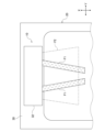
図6、図7、図8を参照する。図6、図7、図8はそれぞれ、図2、図3、図4に対応する。第1の実施の形態との相違点に中心に説明する。
Second Embodiment
Please refer to Figures 6, 7 and 8. Figures 6, 7 and 8 correspond to Figures 2, 3 and 4, respectively. The following mainly describes the differences from the first embodiment.
2つの噴流吐水孔38は、膜状流吐水孔40と上下に重ならない位置に設けられる。言い換えると、2つの噴流吐水孔38はそれぞれ、膜状流吐水孔40の設けられる左右方向Yでの範囲Saの外に設けられる。2つの噴流吐水孔38は、膜状流吐水孔40よりも上方に設けられてもよいし、図示のように膜状流吐水孔40と少なくとも一部が左右に重なる位置に設けられてもよいし、膜状流吐水孔40よりも下方に設けられてもよい。 The two jet water discharge holes 38 are provided at positions that do not overlap vertically with the film-like flow discharge holes 40. In other words, the two jet water discharge holes 38 are provided outside the range Sa in the left-right direction Y in which the film-like flow discharge holes 40 are provided. The two jet water discharge holes 38 may be provided above the film-like flow discharge holes 40, or may be provided at positions that overlap at least partially with the film-like flow discharge holes 40 horizontally as shown, or may be provided below the film-like flow discharge holes 40.
噴流吐水部50、膜状流吐水部52はそれぞれ、正面視において、噴流F1の吐水範囲と膜状流F2の吐水範囲とが重ならないように、噴流F1、膜状流F2を吐水する。言い換えると、噴流吐水部50、膜状流吐水部52はそれぞれ、噴流F1が膜状流の上方および下方のいずれも通らないように噴流F1、膜状流F2を吐水する。より具体的には、噴流吐水部50、膜状流吐水部52はそれぞれ、膜状流F2の左右方向Yの両側において噴流F1がユーザに当たるように噴流F1、膜状流F2を吐水する。
The jet
本実施の形態によれば、膜状流F2の左右方向Yの両側において噴流F1がユーザに当たるように、噴流F1と膜状流F2とを同時にユーザに浴びせることができる。これにより、刺激感を与えつつ、広い範囲を温めることができる。 According to this embodiment, the jet flow F1 and the film-like flow F2 can be simultaneously sprayed onto the user so that the jet flow F1 hits the user on both sides of the film-like flow F2 in the left-right direction Y. This makes it possible to warm a wide area while providing a sensation of stimulation.
以上、本開示について、実施の形態をもとに説明した。この実施の形態は例示であり、それらの各構成要素や各処理プロセスの組み合わせにいろいろな変形例が可能なこと、またそうした変形例も本開示の範囲にあることは当業者に理解されるところである。以下、こうした変形例について説明する。 The present disclosure has been described above based on an embodiment. This embodiment is merely an example, and those skilled in the art will understand that various modifications are possible in the combination of each component and each processing process, and that such modifications are also within the scope of the present disclosure. Below, such modifications are described.
(変形例1)
第1、第2の実施の形態とは異なり、噴流吐水部50は、流れ方向が時間的に変化するように噴流F1を吐水してもよい。
(Variation 1)
Unlike the first and second embodiments, the jet
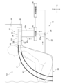
図9、図10を参照する。本変形例では、噴流吐水部50は流体素子44をさらに備える。流体素子44の内部の流路は噴流水路34の一部を構成し、当該流路の下流側端部は噴流吐水孔38を構成する。
See Figures 9 and 10. In this modified example, the jet
流体素子44は、吐水装置10全体の向きを変えることなく、噴流吐水孔38から飛び出るときの流れ方向が時間的に変化するように噴流F1を吐水する。
The
例えば流体素子44は、図10の例では、噴流吐水孔38から飛び出るときの流れ方向を左右方向Yに揺動させるように時間的に変化させる。この場合、噴流吐水部50から波状の噴流F1が放射状に吐水される。図10では波状の噴流F1の吐水範囲S3を一点鎖線で示す。
For example, in the example of Figure 10, the
例えば流体素子44は、所定の軸線に沿った軸方向の速度成分と軸線に直交する径方向の速度成分を有する噴流であって、径方向の速度成分が軸線周りに回転するよう時間的に変化する噴流を吐水するものであってもよい。この場合、噴流吐水部50から螺旋状の噴流F1が放射状に吐水される。
For example, the
流体素子44の具体例は特に限定されない。例えば流体素子44は、内部の合流室内で一対の水流を衝突させることで噴流F1の流れ方向を揺動するものであってもよい。例えば流体素子44は、カルマン渦を利用して噴流F1の流れ方向を揺動するものであってもよいし、コアンダ効果を利用して噴流F1の流れ方向を揺動するものであってもよい。
Specific examples of the
噴流F1の流れ方向が時間的に変化する場合、噴流F1を浴びる箇所は経時的に変化するため、流れ方向が時間的に一定の場合と比べて噴流F1を浴びた箇所に形成される水膜が薄くなり、飛沫が生じやすい。このような状況のもとでも、膜状流F2が形成する水膜Wのクッション機能により、噴流F1による飛沫の飛散を抑止できる。 When the flow direction of the jet F1 changes over time, the location exposed to the jet F1 also changes over time, so the water film formed at the location exposed to the jet F1 becomes thinner and splashes are more likely to occur than when the flow direction is constant over time. Even under these circumstances, the cushioning function of the water film W formed by the film-like flow F2 can prevent splashes caused by the jet F1 from scattering.
噴流F1の流れ方向が時間的に変化する場合、流れ方向が時間的に一定の場合と比べて噴流F1の吐水範囲が広くなる。このような場合でも、噴流F1の吐水範囲が膜状流F2の吐水範囲内に収まることで、噴流F1による飛沫の飛散を効果的に抑止できる。 When the flow direction of the jet F1 changes over time, the jet F1's water discharge range becomes wider than when the flow direction is constant over time. Even in such a case, the jet F1's water discharge range falls within the water discharge range of the film-like flow F2, so that the scattering of droplets caused by the jet F1 can be effectively prevented.
(変形例2)
第1、第2の実施の形態とは異なり、噴流吐水部50は、流量が時間的に変化するように噴流F1を吐水してもよい。
(Variation 2)
Unlike the first and second embodiments, the jet
例えば、噴流吐水部50が気泡供給部をさらに備え、当該気泡供給部が噴流水路34を流れる水に断続的に気泡を供給することで、噴流F1の流れ方向に向かって流量の少ない領域と流量の多い領域を形成してもよい。
For example, the jet
例えば、噴流吐水部50は、噴流吐水孔38から飛び出るときの流量がゼロと正の値との間で時間的に変化するように噴流F1を吐水してもよい。つまり、噴流吐水部50は、噴流F1を断続的に吐水してもよい。これは例えば、噴流水路34の下流側端部に複数の噴流吐水孔38を設け、噴流水路34に配置した羽根車により複数の噴流吐水孔38を開閉することで実現できる。
For example, the jet
噴流F1の流量が時間的に変化する場合、噴流F1を浴びる箇所に形成される水膜の厚みが経時的に変化する。このため、水膜の厚みが薄くなったタイミングで大流量の噴流F1を浴びると、飛沫が生じやすい。このような状況のもとでも、膜状流F2が形成する水膜Wのクッション機能により、噴流F1による飛沫の飛散を抑止できる。 When the flow rate of the jet F1 changes over time, the thickness of the water film formed at the point exposed to the jet F1 also changes over time. For this reason, if the high flow rate of the jet F1 is applied at a time when the thickness of the water film has become thin, splashes are likely to occur. Even under such circumstances, the cushioning function of the water film W formed by the film-like flow F2 can prevent splashes caused by the jet F1 from scattering.
(変形例3)
第1の実施の形態とは異なり、噴流F1の吐水範囲の一部は、正面視において、膜状流F2の吐水範囲外にはみ出てもよい。
(Variation 3)
Unlike the first embodiment, a part of the water discharge range of the jet flow F1 may extend outside the water discharge range of the sheet-like flow F2 in a front view.
(変形例4)
第1の実施の形態では、2つの噴流吐水孔38がそれぞれ、少なくとも一部が膜状流吐水孔40と上下に重なる位置に設けられる場合について説明した。しかしながら、これには限定されず、正面視において、噴流F1の吐水範囲と膜状流F2の吐水範囲とが少なくとも部分的に重なっていればよく、2つの噴流吐水孔38はそれぞれ、膜状流吐水孔40と上下に重ならない位置に設けられてもよい。
(Variation 4)
In the first embodiment, a case has been described in which the two jet water discharge holes 38 are provided at positions where at least a portion of each of them vertically overlaps with the film-like flow water discharge holes 40. However, this is not limited thereto, and it is sufficient that the water discharge range of the jet flow F1 and the water discharge range of the film-like flow F2 at least partially overlap in a front view, and the two jet water discharge holes 38 may be provided at positions where they do not vertically overlap with the film-like flow water discharge holes 40.
(変形例5)
実施の形態とは異なり、槽体20は、浴槽とは別に設けられてもよい。
(Variation 5)
Unlike the embodiment, the
実施の形態とは異なり、ベース30は、槽体20の上面開口部より下方に設けられる槽体20の内周壁部によって構成されてもよいし、衛生設備12の壁体16によって構成されてもよい。つまり、吐水装置10は浴槽14の内周壁部や壁体16に固定されてもよい。
Unlike the embodiment, the
実施の形態とは異なり、衛生設備12は、例えば、キッチン設備、洗面設備、トイレ設備などであってもよい。この場合、槽体20は、例えば、キッチンシンク、手洗シンクなどであってもよい。この場合、ベース30は、キッチンシンクや手洗いシンクのフランジ部であってもよいし、室内空間を区画する壁体であってもよい。
Unlike the embodiment, the
実施の形態とは異なり、噴流吐水部50と膜状流吐水部52は別々の筐体に収容されてもよい。
Unlike the embodiment, the jet
実施の形態とは異なり、吐水システム18は、弁装置24を備えなくてもよい。
Unlike the embodiment, the
実施の形態とは異なり、吐水装置10は、例えば、シャワー装置、水栓装置などとして構成されてもよい。
Unlike the embodiment, the
(変形例6)
弁装置24は、第1下流側水路22bと上流側水路22aを連通し、第2下流側水路22cと上流側水路22aの連通を遮断することが可能であってもよい。この場合、吐水装置10は、噴流F1のみを吐水する。弁装置24は、第2下流側水路22cと上流側水路22aを連通し、第1下流側水路22bと上流側水路22aの連通を遮断することが可能であってもよい。この場合、吐水装置10は、膜状流F2のみを吐水する。
(Variation 6)
The
つまり、吐水装置10は、噴流F1のみを吐水するモード、膜状流F2のみを吐水するモード、および噴流F1および膜状流F2を同時に吐水するモード、の3つの吐水モードを実行可能であってもよい。
In other words, the
実施の形態にもとづき、具体的な語句を用いて本開示を説明した。実施の形態は、本開示の原理、応用の一側面を示しているにすぎず、実施の形態には、請求の範囲に規定された本開示の思想を逸脱しない範囲において、多くの変形例や配置の変更が認められる。 The present disclosure has been described using specific terms based on the embodiments. The embodiments merely show one aspect of the principles and applications of the present disclosure, and many modifications and changes in arrangement are permitted to the embodiments as long as they do not deviate from the ideas of the present disclosure as defined in the claims.
F1 噴流、F2 膜状流、10 吐水装置、50 噴流吐水部、52 膜状流吐水部。 F1 jet, F2 film flow, 10 water discharge device, 50 jet water discharge section, 52 film flow water discharge section.
Claims (3)
噴流を吐水する噴流吐水部と、
流れ方向に直交する断面において有端膜状をなし、前記噴流の下方を通る膜状流を吐水する膜状流吐水部と、
を備え、
前記吐水装置は、槽体に固定され、
前記噴流吐水部は、当該噴流吐水部を飛び出るときの流れ方向および流量の少なくとも一方が時間的に変化するように前記噴流を吐水する吐水装置。 A water discharge device,
a jet water discharge unit that discharges a jet of water;
a film-like flow discharge portion that has an end-shaped film shape in a cross section perpendicular to the flow direction and discharges a film-like flow that passes below the jet;
Equipped with
The water discharge device is fixed to a tank body,
The water jet spouting section spouts the jet of water so that at least one of the flow direction and the flow rate when the jet of water leaves the water jet spouting section changes over time .
前記槽体内に吐水する請求項1または2に記載の吐水装置と、
を備える吐水システム。 The tank body,
The water discharge device according to claim 1 or 2 , which discharges water into the tank body;
A water discharge system comprising:
Priority Applications (1)
| Application Number | Priority Date | Filing Date | Title |
|---|---|---|---|
| JP2020151556A JP7561548B2 (en) | 2020-09-09 | 2020-09-09 | Water discharge device and water discharge system |
Applications Claiming Priority (1)
| Application Number | Priority Date | Filing Date | Title |
|---|---|---|---|
| JP2020151556A JP7561548B2 (en) | 2020-09-09 | 2020-09-09 | Water discharge device and water discharge system |
Publications (2)
| Publication Number | Publication Date |
|---|---|
| JP2022045783A JP2022045783A (en) | 2022-03-22 |
| JP7561548B2 true JP7561548B2 (en) | 2024-10-04 |
Family
ID=80774558
Family Applications (1)
| Application Number | Title | Priority Date | Filing Date |
|---|---|---|---|
| JP2020151556A Active JP7561548B2 (en) | 2020-09-09 | 2020-09-09 | Water discharge device and water discharge system |
Country Status (1)
| Country | Link |
|---|---|
| JP (1) | JP7561548B2 (en) |
Citations (4)
| Publication number | Priority date | Publication date | Assignee | Title |
|---|---|---|---|---|
| JP2004121504A (en) | 2002-10-01 | 2004-04-22 | Noritz Corp | Shower device |
| JP2008043464A (en) | 2006-08-11 | 2008-02-28 | Toto Ltd | Shower bathing apparatus |
| JP2016007361A (en) | 2014-06-24 | 2016-01-18 | 株式会社Lixil | Water discharge device and water discharge device mounting structure |
| JP2017064100A (en) | 2015-09-30 | 2017-04-06 | Toto株式会社 | shower head |
-
2020
- 2020-09-09 JP JP2020151556A patent/JP7561548B2/en active Active
Patent Citations (4)
| Publication number | Priority date | Publication date | Assignee | Title |
|---|---|---|---|---|
| JP2004121504A (en) | 2002-10-01 | 2004-04-22 | Noritz Corp | Shower device |
| JP2008043464A (en) | 2006-08-11 | 2008-02-28 | Toto Ltd | Shower bathing apparatus |
| JP2016007361A (en) | 2014-06-24 | 2016-01-18 | 株式会社Lixil | Water discharge device and water discharge device mounting structure |
| JP2017064100A (en) | 2015-09-30 | 2017-04-06 | Toto株式会社 | shower head |
Also Published As
| Publication number | Publication date |
|---|---|
| JP2022045783A (en) | 2022-03-22 |
Similar Documents
| Publication | Publication Date | Title |
|---|---|---|
| CN102639220B (en) | Bubble generator | |
| EP2354337B1 (en) | Sanitary washing apparatus | |
| CA2928294A1 (en) | Showerhead with scanner nozzles | |
| CN108166588B (en) | Flush toilet | |
| US20170073953A1 (en) | Nozzle assembly and method of controlling the same | |
| JP2007138662A (en) | Shower device | |
| JP7441618B2 (en) | Discharge device and bathroom equipment | |
| JP5966825B2 (en) | shower head | |
| JP7265952B2 (en) | Discharge device and plumbing equipment | |
| JP7561548B2 (en) | Water discharge device and water discharge system | |
| JP7561547B2 (en) | Water discharge device and water discharge system | |
| CN116528987A (en) | Water-saving nozzle and shower head comprising same | |
| KR20150118215A (en) | Bidet including Nozzle Assembly | |
| CN107866338A (en) | A kind of gondola water faucet of improvement | |
| CN216586850U (en) | Spray head | |
| JP2017155410A (en) | Water discharge device | |
| JP7492887B2 (en) | Discharge Device | |
| CN114033005A (en) | Spray head | |
| KR102250713B1 (en) | Swirl generation device for high pressure water spray | |
| JP7329341B2 (en) | discharge device | |
| JP5633784B2 (en) | Shower equipment | |
| JP2007170135A (en) | Shower device | |
| JP7465772B2 (en) | Discharge Device | |
| JP7496267B2 (en) | Discharge Device | |
| CN213868088U (en) | A water outlet structure with face wash |
Legal Events
| Date | Code | Title | Description |
|---|---|---|---|
| A711 | Notification of change in applicant |
Free format text: JAPANESE INTERMEDIATE CODE: A712 Effective date: 20210127 |
|
| A621 | Written request for application examination |
Free format text: JAPANESE INTERMEDIATE CODE: A621 Effective date: 20230703 |
|
| A977 | Report on retrieval |
Free format text: JAPANESE INTERMEDIATE CODE: A971007 Effective date: 20240123 |
|
| A131 | Notification of reasons for refusal |
Free format text: JAPANESE INTERMEDIATE CODE: A131 Effective date: 20240130 |
|
| A601 | Written request for extension of time |
Free format text: JAPANESE INTERMEDIATE CODE: A601 Effective date: 20240329 |
|
| A521 | Request for written amendment filed |
Free format text: JAPANESE INTERMEDIATE CODE: A523 Effective date: 20240522 |
|
| TRDD | Decision of grant or rejection written | ||
| A01 | Written decision to grant a patent or to grant a registration (utility model) |
Free format text: JAPANESE INTERMEDIATE CODE: A01 Effective date: 20240827 |
|
| A61 | First payment of annual fees (during grant procedure) |
Free format text: JAPANESE INTERMEDIATE CODE: A61 Effective date: 20240924 |
|
| R150 | Certificate of patent or registration of utility model |
Ref document number: 7561548 Country of ref document: JP Free format text: JAPANESE INTERMEDIATE CODE: R150 |