JP7561574B2 - Floating body, method for loading liquefied carbon dioxide, and method for unloading liquefied carbon dioxide - Google Patents
Floating body, method for loading liquefied carbon dioxide, and method for unloading liquefied carbon dioxide Download PDFInfo
- Publication number
- JP7561574B2 JP7561574B2 JP2020180559A JP2020180559A JP7561574B2 JP 7561574 B2 JP7561574 B2 JP 7561574B2 JP 2020180559 A JP2020180559 A JP 2020180559A JP 2020180559 A JP2020180559 A JP 2020180559A JP 7561574 B2 JP7561574 B2 JP 7561574B2
- Authority
- JP
- Japan
- Prior art keywords
- tank
- carbon dioxide
- pipe
- liquefied carbon
- loading
- Prior art date
- Legal status (The legal status is an assumption and is not a legal conclusion. Google has not performed a legal analysis and makes no representation as to the accuracy of the status listed.)
- Active
Links
Images


Classifications
-
- F—MECHANICAL ENGINEERING; LIGHTING; HEATING; WEAPONS; BLASTING
- F17—STORING OR DISTRIBUTING GASES OR LIQUIDS
- F17C—VESSELS FOR CONTAINING OR STORING COMPRESSED, LIQUEFIED OR SOLIDIFIED GASES; FIXED-CAPACITY GAS-HOLDERS; FILLING VESSELS WITH, OR DISCHARGING FROM VESSELS, COMPRESSED, LIQUEFIED, OR SOLIDIFIED GASES
- F17C6/00—Methods and apparatus for filling vessels not under pressure with liquefied or solidified gases
-
- B—PERFORMING OPERATIONS; TRANSPORTING
- B63—SHIPS OR OTHER WATERBORNE VESSELS; RELATED EQUIPMENT
- B63B—SHIPS OR OTHER WATERBORNE VESSELS; EQUIPMENT FOR SHIPPING
- B63B25/00—Load-accommodating arrangements, e.g. stowing, trimming; Vessels characterised thereby
- B63B25/02—Load-accommodating arrangements, e.g. stowing, trimming; Vessels characterised thereby for bulk goods
- B63B25/08—Load-accommodating arrangements, e.g. stowing, trimming; Vessels characterised thereby for bulk goods fluid
- B63B25/12—Load-accommodating arrangements, e.g. stowing, trimming; Vessels characterised thereby for bulk goods fluid closed
- B63B25/16—Load-accommodating arrangements, e.g. stowing, trimming; Vessels characterised thereby for bulk goods fluid closed heat-insulated
-
- B—PERFORMING OPERATIONS; TRANSPORTING
- B63—SHIPS OR OTHER WATERBORNE VESSELS; RELATED EQUIPMENT
- B63B—SHIPS OR OTHER WATERBORNE VESSELS; EQUIPMENT FOR SHIPPING
- B63B27/00—Arrangement of ship-based loading or unloading equipment for cargo or passengers
- B63B27/24—Arrangement of ship-based loading or unloading equipment for cargo or passengers of pipe-lines
-
- F—MECHANICAL ENGINEERING; LIGHTING; HEATING; WEAPONS; BLASTING
- F17—STORING OR DISTRIBUTING GASES OR LIQUIDS
- F17C—VESSELS FOR CONTAINING OR STORING COMPRESSED, LIQUEFIED OR SOLIDIFIED GASES; FIXED-CAPACITY GAS-HOLDERS; FILLING VESSELS WITH, OR DISCHARGING FROM VESSELS, COMPRESSED, LIQUEFIED, OR SOLIDIFIED GASES
- F17C2201/00—Vessel construction, in particular geometry, arrangement or size
- F17C2201/01—Shape
- F17C2201/0104—Shape cylindrical
- F17C2201/0109—Shape cylindrical with exteriorly curved end-piece
-
- F—MECHANICAL ENGINEERING; LIGHTING; HEATING; WEAPONS; BLASTING
- F17—STORING OR DISTRIBUTING GASES OR LIQUIDS
- F17C—VESSELS FOR CONTAINING OR STORING COMPRESSED, LIQUEFIED OR SOLIDIFIED GASES; FIXED-CAPACITY GAS-HOLDERS; FILLING VESSELS WITH, OR DISCHARGING FROM VESSELS, COMPRESSED, LIQUEFIED, OR SOLIDIFIED GASES
- F17C2201/00—Vessel construction, in particular geometry, arrangement or size
- F17C2201/01—Shape
- F17C2201/0128—Shape spherical or elliptical
-
- F—MECHANICAL ENGINEERING; LIGHTING; HEATING; WEAPONS; BLASTING
- F17—STORING OR DISTRIBUTING GASES OR LIQUIDS
- F17C—VESSELS FOR CONTAINING OR STORING COMPRESSED, LIQUEFIED OR SOLIDIFIED GASES; FIXED-CAPACITY GAS-HOLDERS; FILLING VESSELS WITH, OR DISCHARGING FROM VESSELS, COMPRESSED, LIQUEFIED, OR SOLIDIFIED GASES
- F17C2201/00—Vessel construction, in particular geometry, arrangement or size
- F17C2201/01—Shape
- F17C2201/0147—Shape complex
- F17C2201/0157—Polygonal
-
- F—MECHANICAL ENGINEERING; LIGHTING; HEATING; WEAPONS; BLASTING
- F17—STORING OR DISTRIBUTING GASES OR LIQUIDS
- F17C—VESSELS FOR CONTAINING OR STORING COMPRESSED, LIQUEFIED OR SOLIDIFIED GASES; FIXED-CAPACITY GAS-HOLDERS; FILLING VESSELS WITH, OR DISCHARGING FROM VESSELS, COMPRESSED, LIQUEFIED, OR SOLIDIFIED GASES
- F17C2201/00—Vessel construction, in particular geometry, arrangement or size
- F17C2201/03—Orientation
- F17C2201/035—Orientation with substantially horizontal main axis
-
- F—MECHANICAL ENGINEERING; LIGHTING; HEATING; WEAPONS; BLASTING
- F17—STORING OR DISTRIBUTING GASES OR LIQUIDS
- F17C—VESSELS FOR CONTAINING OR STORING COMPRESSED, LIQUEFIED OR SOLIDIFIED GASES; FIXED-CAPACITY GAS-HOLDERS; FILLING VESSELS WITH, OR DISCHARGING FROM VESSELS, COMPRESSED, LIQUEFIED, OR SOLIDIFIED GASES
- F17C2201/00—Vessel construction, in particular geometry, arrangement or size
- F17C2201/05—Size
- F17C2201/052—Size large (>1000 m3)
-
- F—MECHANICAL ENGINEERING; LIGHTING; HEATING; WEAPONS; BLASTING
- F17—STORING OR DISTRIBUTING GASES OR LIQUIDS
- F17C—VESSELS FOR CONTAINING OR STORING COMPRESSED, LIQUEFIED OR SOLIDIFIED GASES; FIXED-CAPACITY GAS-HOLDERS; FILLING VESSELS WITH, OR DISCHARGING FROM VESSELS, COMPRESSED, LIQUEFIED, OR SOLIDIFIED GASES
- F17C2205/00—Vessel construction, in particular mounting arrangements, attachments or identifications means
- F17C2205/01—Mounting arrangements
- F17C2205/0123—Mounting arrangements characterised by number of vessels
- F17C2205/013—Two or more vessels
- F17C2205/0134—Two or more vessels characterised by the presence of fluid connection between vessels
- F17C2205/0138—Two or more vessels characterised by the presence of fluid connection between vessels bundled in series
-
- F—MECHANICAL ENGINEERING; LIGHTING; HEATING; WEAPONS; BLASTING
- F17—STORING OR DISTRIBUTING GASES OR LIQUIDS
- F17C—VESSELS FOR CONTAINING OR STORING COMPRESSED, LIQUEFIED OR SOLIDIFIED GASES; FIXED-CAPACITY GAS-HOLDERS; FILLING VESSELS WITH, OR DISCHARGING FROM VESSELS, COMPRESSED, LIQUEFIED, OR SOLIDIFIED GASES
- F17C2205/00—Vessel construction, in particular mounting arrangements, attachments or identifications means
- F17C2205/03—Fluid connections, filters, valves, closure means or other attachments
- F17C2205/0302—Fittings, valves, filters, or components in connection with the gas storage device
- F17C2205/0352—Pipes
-
- F—MECHANICAL ENGINEERING; LIGHTING; HEATING; WEAPONS; BLASTING
- F17—STORING OR DISTRIBUTING GASES OR LIQUIDS
- F17C—VESSELS FOR CONTAINING OR STORING COMPRESSED, LIQUEFIED OR SOLIDIFIED GASES; FIXED-CAPACITY GAS-HOLDERS; FILLING VESSELS WITH, OR DISCHARGING FROM VESSELS, COMPRESSED, LIQUEFIED, OR SOLIDIFIED GASES
- F17C2221/00—Handled fluid, in particular type of fluid
- F17C2221/01—Pure fluids
- F17C2221/013—Carbon dioxide
-
- F—MECHANICAL ENGINEERING; LIGHTING; HEATING; WEAPONS; BLASTING
- F17—STORING OR DISTRIBUTING GASES OR LIQUIDS
- F17C—VESSELS FOR CONTAINING OR STORING COMPRESSED, LIQUEFIED OR SOLIDIFIED GASES; FIXED-CAPACITY GAS-HOLDERS; FILLING VESSELS WITH, OR DISCHARGING FROM VESSELS, COMPRESSED, LIQUEFIED, OR SOLIDIFIED GASES
- F17C2223/00—Handled fluid before transfer, i.e. state of fluid when stored in the vessel or before transfer from the vessel
- F17C2223/01—Handled fluid before transfer, i.e. state of fluid when stored in the vessel or before transfer from the vessel characterised by the phase
- F17C2223/0146—Two-phase
- F17C2223/0153—Liquefied gas, e.g. LPG, GPL
-
- F—MECHANICAL ENGINEERING; LIGHTING; HEATING; WEAPONS; BLASTING
- F17—STORING OR DISTRIBUTING GASES OR LIQUIDS
- F17C—VESSELS FOR CONTAINING OR STORING COMPRESSED, LIQUEFIED OR SOLIDIFIED GASES; FIXED-CAPACITY GAS-HOLDERS; FILLING VESSELS WITH, OR DISCHARGING FROM VESSELS, COMPRESSED, LIQUEFIED, OR SOLIDIFIED GASES
- F17C2223/00—Handled fluid before transfer, i.e. state of fluid when stored in the vessel or before transfer from the vessel
- F17C2223/01—Handled fluid before transfer, i.e. state of fluid when stored in the vessel or before transfer from the vessel characterised by the phase
- F17C2223/0192—Three-phase, e.g. CO2 at triple point
-
- F—MECHANICAL ENGINEERING; LIGHTING; HEATING; WEAPONS; BLASTING
- F17—STORING OR DISTRIBUTING GASES OR LIQUIDS
- F17C—VESSELS FOR CONTAINING OR STORING COMPRESSED, LIQUEFIED OR SOLIDIFIED GASES; FIXED-CAPACITY GAS-HOLDERS; FILLING VESSELS WITH, OR DISCHARGING FROM VESSELS, COMPRESSED, LIQUEFIED, OR SOLIDIFIED GASES
- F17C2223/00—Handled fluid before transfer, i.e. state of fluid when stored in the vessel or before transfer from the vessel
- F17C2223/04—Handled fluid before transfer, i.e. state of fluid when stored in the vessel or before transfer from the vessel characterised by other properties of handled fluid before transfer
- F17C2223/042—Localisation of the removal point
- F17C2223/046—Localisation of the removal point in the liquid
- F17C2223/047—Localisation of the removal point in the liquid with a dip tube
-
- F—MECHANICAL ENGINEERING; LIGHTING; HEATING; WEAPONS; BLASTING
- F17—STORING OR DISTRIBUTING GASES OR LIQUIDS
- F17C—VESSELS FOR CONTAINING OR STORING COMPRESSED, LIQUEFIED OR SOLIDIFIED GASES; FIXED-CAPACITY GAS-HOLDERS; FILLING VESSELS WITH, OR DISCHARGING FROM VESSELS, COMPRESSED, LIQUEFIED, OR SOLIDIFIED GASES
- F17C2225/00—Handled fluid after transfer, i.e. state of fluid after transfer from the vessel
- F17C2225/04—Handled fluid after transfer, i.e. state of fluid after transfer from the vessel characterised by other properties of handled fluid after transfer
- F17C2225/042—Localisation of the filling point
- F17C2225/046—Localisation of the filling point in the liquid
- F17C2225/047—Localisation of the filling point in the liquid with a dip tube
-
- F—MECHANICAL ENGINEERING; LIGHTING; HEATING; WEAPONS; BLASTING
- F17—STORING OR DISTRIBUTING GASES OR LIQUIDS
- F17C—VESSELS FOR CONTAINING OR STORING COMPRESSED, LIQUEFIED OR SOLIDIFIED GASES; FIXED-CAPACITY GAS-HOLDERS; FILLING VESSELS WITH, OR DISCHARGING FROM VESSELS, COMPRESSED, LIQUEFIED, OR SOLIDIFIED GASES
- F17C2227/00—Transfer of fluids, i.e. method or means for transferring the fluid; Heat exchange with the fluid
- F17C2227/01—Propulsion of the fluid
- F17C2227/0128—Propulsion of the fluid with pumps or compressors
- F17C2227/0135—Pumps
-
- F—MECHANICAL ENGINEERING; LIGHTING; HEATING; WEAPONS; BLASTING
- F17—STORING OR DISTRIBUTING GASES OR LIQUIDS
- F17C—VESSELS FOR CONTAINING OR STORING COMPRESSED, LIQUEFIED OR SOLIDIFIED GASES; FIXED-CAPACITY GAS-HOLDERS; FILLING VESSELS WITH, OR DISCHARGING FROM VESSELS, COMPRESSED, LIQUEFIED, OR SOLIDIFIED GASES
- F17C2227/00—Transfer of fluids, i.e. method or means for transferring the fluid; Heat exchange with the fluid
- F17C2227/01—Propulsion of the fluid
- F17C2227/0128—Propulsion of the fluid with pumps or compressors
- F17C2227/0171—Arrangement
- F17C2227/0178—Arrangement in the vessel
-
- F—MECHANICAL ENGINEERING; LIGHTING; HEATING; WEAPONS; BLASTING
- F17—STORING OR DISTRIBUTING GASES OR LIQUIDS
- F17C—VESSELS FOR CONTAINING OR STORING COMPRESSED, LIQUEFIED OR SOLIDIFIED GASES; FIXED-CAPACITY GAS-HOLDERS; FILLING VESSELS WITH, OR DISCHARGING FROM VESSELS, COMPRESSED, LIQUEFIED, OR SOLIDIFIED GASES
- F17C2227/00—Transfer of fluids, i.e. method or means for transferring the fluid; Heat exchange with the fluid
- F17C2227/04—Methods for emptying or filling
-
- F—MECHANICAL ENGINEERING; LIGHTING; HEATING; WEAPONS; BLASTING
- F17—STORING OR DISTRIBUTING GASES OR LIQUIDS
- F17C—VESSELS FOR CONTAINING OR STORING COMPRESSED, LIQUEFIED OR SOLIDIFIED GASES; FIXED-CAPACITY GAS-HOLDERS; FILLING VESSELS WITH, OR DISCHARGING FROM VESSELS, COMPRESSED, LIQUEFIED, OR SOLIDIFIED GASES
- F17C2260/00—Purposes of gas storage and gas handling
- F17C2260/02—Improving properties related to fluid or fluid transfer
- F17C2260/026—Improving properties related to fluid or fluid transfer by calculation
-
- F—MECHANICAL ENGINEERING; LIGHTING; HEATING; WEAPONS; BLASTING
- F17—STORING OR DISTRIBUTING GASES OR LIQUIDS
- F17C—VESSELS FOR CONTAINING OR STORING COMPRESSED, LIQUEFIED OR SOLIDIFIED GASES; FIXED-CAPACITY GAS-HOLDERS; FILLING VESSELS WITH, OR DISCHARGING FROM VESSELS, COMPRESSED, LIQUEFIED, OR SOLIDIFIED GASES
- F17C2260/00—Purposes of gas storage and gas handling
- F17C2260/03—Dealing with losses
- F17C2260/031—Dealing with losses due to heat transfer
- F17C2260/032—Avoiding freezing or defrosting
-
- F—MECHANICAL ENGINEERING; LIGHTING; HEATING; WEAPONS; BLASTING
- F17—STORING OR DISTRIBUTING GASES OR LIQUIDS
- F17C—VESSELS FOR CONTAINING OR STORING COMPRESSED, LIQUEFIED OR SOLIDIFIED GASES; FIXED-CAPACITY GAS-HOLDERS; FILLING VESSELS WITH, OR DISCHARGING FROM VESSELS, COMPRESSED, LIQUEFIED, OR SOLIDIFIED GASES
- F17C2270/00—Applications
- F17C2270/01—Applications for fluid transport or storage
- F17C2270/0102—Applications for fluid transport or storage on or in the water
- F17C2270/0105—Ships
-
- F—MECHANICAL ENGINEERING; LIGHTING; HEATING; WEAPONS; BLASTING
- F17—STORING OR DISTRIBUTING GASES OR LIQUIDS
- F17C—VESSELS FOR CONTAINING OR STORING COMPRESSED, LIQUEFIED OR SOLIDIFIED GASES; FIXED-CAPACITY GAS-HOLDERS; FILLING VESSELS WITH, OR DISCHARGING FROM VESSELS, COMPRESSED, LIQUEFIED, OR SOLIDIFIED GASES
- F17C2270/00—Applications
- F17C2270/01—Applications for fluid transport or storage
- F17C2270/0102—Applications for fluid transport or storage on or in the water
- F17C2270/011—Barges
- F17C2270/0113—Barges floating
Landscapes
- Engineering & Computer Science (AREA)
- Mechanical Engineering (AREA)
- Chemical & Material Sciences (AREA)
- Combustion & Propulsion (AREA)
- Ocean & Marine Engineering (AREA)
- General Engineering & Computer Science (AREA)
- Filling Or Discharging Of Gas Storage Vessels (AREA)
- Organic Low-Molecular-Weight Compounds And Preparation Thereof (AREA)
- Carbon And Carbon Compounds (AREA)
Description
本開示は、浮体、液化二酸化炭素の積込方法、液化二酸化炭素の揚荷方法に関する。 This disclosure relates to a floating body, a method for loading liquefied carbon dioxide, and a method for unloading liquefied carbon dioxide.
例えば特許文献1に開示された燃料タンクは、液化ガス(LNG:Liquefied Natural Gas)を燃料タンクに積み込むための積込配管(パイプライン)を備える構成が開示されている。 For example, the fuel tank disclosed in Patent Document 1 is configured to include a loading pipe (pipeline) for loading liquefied natural gas (LNG) into the fuel tank.
ところで、タンク内に液化二酸化炭素を収容する場合、以下のような理由により、液化二酸化炭素が凝固してドライアイスが生成される可能性がある。すなわち、タンク内で開口する積込配管や揚荷配管の配管下端における液化二酸化炭素の圧力は、タンク運用圧に応じたものとなる。特許文献1に開示されたような構成では、積込配管や揚荷配管において最も高い位置となる配管頂部は、タンク内の最高液位よりも上方に位置する。配管頂部における液化二酸化炭素の圧力は、配管下端における液化二酸化炭素の圧力に対し、タンク内の液化二酸化炭素の液面と配管頂部との高低差によるヘッド圧に応じた分だけ低くなる。つまり、積込配管や揚荷配管においては、配管頂部における液化二酸化炭素の圧力が、タンク内における液化二酸化炭素の圧力よりも低くなる。 When liquefied carbon dioxide is stored in a tank, the liquefied carbon dioxide may solidify and produce dry ice for the following reasons. That is, the pressure of the liquefied carbon dioxide at the lower end of the loading pipe or the unloading pipe that opens into the tank corresponds to the tank operating pressure. In the configuration disclosed in Patent Document 1, the top of the pipe, which is the highest position in the loading pipe or the unloading pipe, is located above the highest liquid level in the tank. The pressure of the liquefied carbon dioxide at the top of the pipe is lower than the pressure of the liquefied carbon dioxide at the lower end of the pipe by an amount corresponding to the head pressure due to the height difference between the liquid level of the liquefied carbon dioxide in the tank and the top of the pipe. That is, in the loading pipe or the unloading pipe, the pressure of the liquefied carbon dioxide at the top of the pipe is lower than the pressure of the liquefied carbon dioxide in the tank.
液化二酸化炭素は、気相、液相、固相が共存する三重点の圧力(三重点圧力)が、LNGやLPGの三重点圧力に比較して高く、運用時におけるタンク運用圧との差異が小さい。その結果、タンク運用圧(タンクの設計圧力)によっては、液化二酸化炭素の圧力が最も低くなる配管頂部において、液化二酸化炭素の圧力が三重点圧力以下となり、液化二酸化炭素のフラッシュ蒸発が生じることがある。すると、液化二酸化炭素のフラッシュ蒸発の蒸発潜熱により、蒸発せずに残った液化二酸化炭素の温度低下が生じ、配管頂部内で液化二酸化炭素が凝固してドライアイスが生成される。積込配管や揚荷配管内でドライアイスが生成されると、配管内における液化二酸化炭素の流れが阻害され、液化二酸化炭素の積込・揚荷作業に影響を及ぼすことがある。 The triple point pressure of liquefied carbon dioxide, where the gas, liquid, and solid phases coexist (triple point pressure), is higher than that of LNG or LPG, and the difference with the tank operating pressure during operation is small. As a result, depending on the tank operating pressure (tank design pressure), the pressure of liquefied carbon dioxide at the top of the piping, where the pressure of liquefied carbon dioxide is lowest, may fall below the triple point pressure, causing flash evaporation of liquefied carbon dioxide. The latent heat of evaporation of liquefied carbon dioxide then causes a drop in the temperature of the liquefied carbon dioxide that remains unevaporated, causing the liquefied carbon dioxide to solidify at the top of the piping and produce dry ice. If dry ice is produced in the loading or unloading piping, the flow of liquefied carbon dioxide in the piping is obstructed, which may affect the loading and unloading operations of liquefied carbon dioxide.
本開示は、上記課題を解決するためになされたものであって、配管内のドライアイス生成を抑え、液化二酸化炭素の積込・揚荷作業を円滑に行うことができる浮体、液化二酸化炭素の積込方法、液化二酸化炭素の揚荷方法を提供することを目的とする。 The present disclosure has been made to solve the above problems, and aims to provide a float that suppresses the generation of dry ice in the piping and enables smooth loading and unloading of liquefied carbon dioxide, a method for loading liquefied carbon dioxide, and a method for unloading liquefied carbon dioxide.
上記課題を解決するために、本開示に係る浮体は、浮体本体と、タンクと、積込配管と、を備える。前記タンクは、前記浮体本体に配置されている。前記タンクは、液化二酸化炭素を貯留可能である。前記積込配管は、外部から供給される液化二酸化炭素を前記タンク内に放出する。前記積込配管は、第一積込配管と、第二積込配管と、を備える。第一積込配管は、前記タンクの外部に配置されて前記タンクの上方で水平方向に延びている。前記第一積込配管は、第一の内径を有している。前記第二積込配管は、一端が前記第一積込配管に接続されて前記タンクの外部から内部に延びるとともに、前記タンク内で上下方向に延び、上下方向における下側端である他端が前記タンク内で開口している。前記第二積込配管は、前記第一の内径よりも小さい第二の内径を有している。 In order to solve the above problems, a float according to the present disclosure includes a float body, a tank, and a loading pipe. The tank is disposed in the float body. The tank is capable of storing liquefied carbon dioxide. The loading pipe discharges liquefied carbon dioxide supplied from the outside into the tank. The loading pipe includes a first loading pipe and a second loading pipe. The first loading pipe is disposed outside the tank and extends horizontally above the tank. The first loading pipe has a first inner diameter. The second loading pipe has one end connected to the first loading pipe and extends from the outside to the inside of the tank, and extends in the vertical direction within the tank, with the other end, which is the lower end in the vertical direction, opening within the tank. The second loading pipe has a second inner diameter smaller than the first inner diameter.
本開示に係る浮体は、浮体本体と、複数のタンクと、揚荷配管と、移送配管と、を備えている。前記タンクは、前記浮体本体に配置されている。前記タンクは、液化二酸化炭素を貯留可能である。前記揚荷配管は、複数の前記タンクのそれぞれに設けられている。前記揚荷配管は、前記タンク内の液化二酸化炭素を前記浮体本体の外部に送り出す。前記移送配管は、第一の前記タンクと第二の前記タンクとの間に跨がるように配置されている。前記移送配管は、前記第一のタンク内と前記第二のタンク内とを連通させる。前記移送配管は、第一移送配管と、第二移送配管と、を備えている。前記第一移送配管は、前記第一のタンク側に配置されている。前記移送配管は、第一の内径を有している。前記第二移送配管は、一端が前記第一移送配管に接続されるとともに、他端が前記第二のタンク内で開口している。前記第二移送配管は、前記第一の内径よりも小さい第二の内径を有している。前記第一移送配管は、前記第一のタンクと前記第二のタンクとの双方の外部に配置されて、前記第一のタンク及び前記第二のタンクの上方で水平方向に延びる中間部を備え、前記第二移送配管は、前記第二のタンクの外部から内部に延びるとともに、前記第二のタンク内で上下方向に延びて、前記第二移送配管の下側端が前記他端として前記第二のタンク内で開口している。 The float according to the present disclosure comprises a float body, a plurality of tanks, a lifting pipe, and a transfer pipe. The tank is disposed in the float body. The tank is capable of storing liquefied carbon dioxide. The lifting pipe is provided in each of the plurality of tanks. The lifting pipe sends out the liquefied carbon dioxide in the tank to the outside of the float body. The transfer pipe is disposed so as to straddle between the first tank and the second tank. The transfer pipe communicates the inside of the first tank with the inside of the second tank. The transfer pipe comprises a first transfer pipe and a second transfer pipe. The first transfer pipe is disposed on the first tank side. The transfer pipe has a first inner diameter. One end of the second transfer pipe is connected to the first transfer pipe, and the other end opens in the second tank. The second transfer pipe has a second inner diameter smaller than the first inner diameter. The first transfer piping is arranged outside both the first tank and the second tank and has an intermediate portion extending horizontally above the first tank and the second tank, and the second transfer piping extends from the outside to the inside of the second tank and extends in the vertical direction within the second tank , with the lower end of the second transfer piping opening within the second tank as the other end .
本開示に係る液化二酸化炭素の積込方法は、上記したような浮体における、液化二酸化炭素の積込方法である。液化二酸化炭素の積込方法は、前記第一積込配管から前記第二積込配管を通して前記タンク内に液化二酸化炭素を積み込む工程と、前記タンク内の液化二酸化炭素の液位が定められた液位に到達したら、前記第一積込配管から前記第三積込配管を通して前記タンク内に液化二酸化炭素を積み込む工程と、を含む。 The method of loading liquefied carbon dioxide according to the present disclosure is a method of loading liquefied carbon dioxide in a floating body as described above. The method of loading liquefied carbon dioxide includes a step of loading liquefied carbon dioxide into the tank from the first loading pipe through the second loading pipe, and a step of loading liquefied carbon dioxide into the tank from the first loading pipe through the third loading pipe when the liquid level of the liquefied carbon dioxide in the tank reaches a predetermined liquid level.
本開示に係る液化二酸化炭素の揚荷方法は、上記したような浮体における、液化二酸化炭素の揚荷方法である。液化二酸化炭素の揚荷方法は、前記第一のタンク内を加圧することで、前記第一のタンク内の液化二酸化炭素を、前記第一移送配管から前記第二移送配管を通して前記第二のタンク内に移送する工程と、前記第二のタンク内の液化二酸化炭素の液位が定められた液位に到達したら、前記第一のタンク内の液化二酸化炭素を、前記第一移送配管から前記第三移送配管を通して前記第二のタンク内に移送する工程と、前記第二のタンク内の前記液化二酸化炭素を、前記揚荷配管により前記第二のタンクの外部に送り出す工程と、を含む。 The method for unloading liquefied carbon dioxide according to the present disclosure is a method for unloading liquefied carbon dioxide in a floating body as described above. The method for unloading liquefied carbon dioxide includes the steps of: pressurizing the inside of the first tank to transfer the liquefied carbon dioxide in the first tank from the first transfer pipe through the second transfer pipe to the second tank; when the liquid level of the liquefied carbon dioxide in the second tank reaches a predetermined liquid level, transferring the liquefied carbon dioxide in the first tank from the first transfer pipe to the second tank through the third transfer pipe; and sending the liquefied carbon dioxide in the second tank to the outside of the second tank through the unloading pipe.
本開示の浮体、液化二酸化炭素の積込方法、液化二酸化炭素の揚荷方法によれば、配管内のドライアイス生成を抑え、積込・揚荷作業を円滑に行うことができる。 The float, liquefied carbon dioxide loading method, and liquefied carbon dioxide unloading method disclosed herein can suppress the generation of dry ice in the piping and facilitate loading and unloading operations.
以下、本開示の実施形態に係る浮体、液化二酸化炭素の積込方法、液化二酸化炭素の揚荷方法について、図1~図11を参照して説明する。
<第一実施形態>
(船舶の構成)
図1に示すように、本開示の実施形態において、浮体である船舶1は、液化二酸化炭素を運搬する。この船舶1は、浮体本体としての船体2と、タンク設備10Aと、を少なくとも備えている。
Hereinafter, a float, a method for loading liquefied carbon dioxide, and a method for unloading liquefied carbon dioxide according to an embodiment of the present disclosure will be described with reference to Figures 1 to 11.
First Embodiment
(Vessel configuration)
As shown in Fig. 1, in the embodiment of the present disclosure, a ship 1, which is a floating body, transports liquefied carbon dioxide. The ship 1 includes at least a
(船体の構成)
船体2は、その外殻をなす、一対の舷側3A,3Bと、船底(図示無し)と、上甲板5と、を有している。舷側3A,3Bは、左右舷側をそれぞれ形成する一対の舷側外板を有する。船底(図示無し)は、これら舷側3A,3Bを接続する船底外板を有する。これら一対の舷側3A,3B及び船底(図示無し)により、船体2の外殻は、船首尾方向Daに直交する断面において、U字状を成している。この実施形態で例示する上甲板5は、外部に露出する全通甲板である。船体2には、船尾2b側の上甲板5上に、居住区を有する上部構造7が形成されている。
(Hull configuration)
The
船体2内には、上部構造7よりも船首2a側に、貨物搭載区画(ホールド)8が形成されている。貨物搭載区画8は、上甲板5に対して下方の船底に向けて凹み、上方に開口している。
A
(タンク設備の構成)
タンク設備10Aは、貨物搭載区画8内に、船首尾方向Daに沿って、複数が配置されている。本開示の実施形態において、タンク設備10Aは、船首尾方向Daに間隔を空けて二個配置されている。
(Tank equipment configuration)
A plurality of
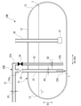
図2に示すように、タンク設備10Aは、タンク11と、積込配管20Aと、揚荷配管30と、を少なくとも備えている。
この実施形態において、タンク11は、船体2に配置されている。タンク11は、例えば、水平方向に延びる円筒状をなす。タンク11は、その内部に液化二酸化炭素Lを収容する。タンク本体は、筒状部12と、端部球状部13と、を備えている。筒状部12は、水平方向を長手方向Dxとして延びている。この実施形態において、筒状部12は、長手方向Dxに直交する断面形状が円形の、円筒状に形成されている。端部球状部13は、筒状部12の長手方向Dxの両端部にそれぞれ配置されている。各端部球状部13は、半球状で、筒状部12の長手方向Dx両端の開口を閉塞している。なお、タンク11は、円筒状に限られるものではなく、タンク11は球形、方形等であってもよい。
As shown in FIG. 2 , the
In this embodiment, the
積込配管20Aは、陸上の液化二酸化炭素供給施設等、船外から供給される液化二酸化炭素Lをタンク11内に積み込む。積込配管20Aは、第一積込配管21と、第二積込配管22と、を備えている。
The
第一積込配管21は、船外の液化二酸化炭素供給施設等から液化二酸化炭素が供給される供給管(図示無し)が着脱可能に接続される。第一積込配管21は、タンク11の外部に配置されている。この実施形態における第一積込配管21は、タンク11の上下方向Dvの上方で、水平方向に延びている。第一積込配管21は、第一の内径D1を有している。
The
第二積込配管22の一端22a(言い換えれば、上下方向Dvにおける上側端)は、第一積込配管21に接続されている。第二積込配管22は、タンク11の頂部を貫通してタンク11の外部から内部に延びている。第二積込配管22は、タンク11内で上下方向Dvに延びている。第二積込配管22の他端22b(言い換えれば、上下方向Dvにおける下側端)は、タンク11内の下部で下方を向いて開口している。第二積込配管22は、第一の内径D1よりも小さい第二の内径D2を有している。この実施形態において、第二積込配管22は、その全長にわたって第二の内径D2を有している。第二積込配管22は、他端22b側の一定長のみを、第二の内径D2で形成し、一端22a側は、第一積込配管21と同じ第一の内径D1で形成してもよい。
One
揚荷配管30は、タンク11内の液化二酸化炭素Lを、陸上の液化二酸化炭素供給施設等、船外に送出する。揚荷配管30は、タンク11の外部からタンク11の頂部を貫通し、タンク11の内部に延びている。揚荷配管30の先端部は、タンク11内の下部に配置されている。揚荷配管30の先端部には、ポンプ31が設けられている。ポンプ31は、タンク11内の液化二酸化炭素Lを吸い込む。揚荷配管30は、ポンプ31で吸い込んだ液化二酸化炭素Lを、タンク11外(船外)に送出する。
The
(作用効果)
上述したような船舶1では、液化二酸化炭素Lが、第一積込配管21から第二積込配管22を通してタンク11内に積み込まれる。第二積込配管22の第二の内径D2は、第一積込配管21の第一の内径D1よりも小さい。そのため、第二積込配管22では、第一積込配管21よりも、圧力損失ΔPが大きくなる。
(Action and Effect)
In the ship 1 as described above, the liquefied carbon dioxide L is loaded into the
ここで、積込配管20Aの配管頂部における液化二酸化炭素Lの圧力PLは、下式(1)で表される。
PL=PT-ρg(h2-h1)/1000+ΔP ・・・(1)
ただし、
PL:積込配管20Aの配管頂部における液化二酸化炭素Lの圧力(kPaG)
PT:タンク11の上部における液化二酸化炭素Lの圧力(kPaG)
ρ:液化二酸化炭素Lの液密度(kg/m3)
g:重力加速度(m/s2)
h2:タンク11の最下部から積込配管20Aの配管頂部までの高さ(m)
h1:タンク11の最下部から液化二酸化炭素Lの液面までの高さ(m)
Here, the pressure P L of the liquefied carbon dioxide L at the top of the
PL = PT - ρg (h 2 - h 1 )/1000+ΔP (1)
however,
P L : Pressure of liquefied carbon dioxide L at the top of the
P T : Pressure of the liquefied carbon dioxide L at the top of the tank 11 (kPaG)
ρ: Liquid density of liquefied carbon dioxide L (kg/m 3 )
g: Gravitational acceleration (m/s 2 )
h2 : Height (m) from the bottom of the
h 1 : Height from the bottom of the
上式(1)により、積込配管20Aの配管頂部における液化二酸化炭素Lの圧力(PL)は、圧力損失ΔPの分だけ高められる。積込配管20Aの配管頂部における液化二酸化炭素Lの圧力が高められることで、液化二酸化炭素Lの圧力が三重点圧力に近づくことが抑えられる。これにより、積込配管20A内で液化二酸化炭素Lが凝固してドライアイスが生成されることが抑えられる。その結果、タンク11内に液化二酸化炭素Lを収容する場合において、積込配管20A内のドライアイス生成を抑え、積込作業を円滑に行うことが可能となる。
According to the above formula (1), the pressure (P L ) of the liquefied carbon dioxide L at the top of the
<第二実施形態>
次に、本開示に係る浮体、液化二酸化炭素の積込方法の第二実施形態について説明する。以下に説明する第二実施形態においては、第一実施形態と第三積込配管23を備える構成のみが異なるので、第一実施形態と同一部分に同一符号を付して説明するとともに、重複説明を省略する。
Second Embodiment
Next, a second embodiment of the floating body and the method for loading liquefied carbon dioxide according to the present disclosure will be described. The second embodiment described below differs from the first embodiment only in that it includes a
図3に示すように、タンク設備10Bは、タンク11と、積込配管20Bと、揚荷配管30と、を少なくとも備えている。
積込配管20Bは、陸上の液化二酸化炭素供給施設等、船外から供給される液化二酸化炭素Lをタンク11内に積み込む。積込配管20Bは、第一積込配管21と、第二積込配管22と、第三積込配管23と、を備えている。
As shown in FIG. 3 , the
The
第一積込配管21は、船外の液化二酸化炭素供給施設等から液化二酸化炭素が供給される供給管(図示無し)が着脱可能に接続される。第一積込配管21は、タンク11の外部に配置されている。第一実施形態の同様に、第一積込配管21は、タンク11の上下方向Dvの上方で、水平方向に延びている。第一積込配管21は、第一の内径D1を有している。
The
第二積込配管22の一端22a(言い換えれば、上下方向Dvにおける上側端)は、第一積込配管21に接続されている。第二積込配管22は、タンク11の頂部を貫通してタンク11の外部から内部に延びている。第二積込配管22は、タンク11内で上下方向Dvに延びている。第二積込配管22の他端22b(言い換えれば、上下方向Dvにおける上側端)は、タンク11内の下部で下方を向いて開口している。第二積込配管22は、第一の内径D1よりも小さい第二の内径D2を有している。
One
第三積込配管23の基端23a(言い換えれば、上下方向Dvにおける上側端)は、第一積込配管21に接続されている。第三積込配管23は、タンク11の頂部を貫通してタンク11の外部から内部に延びている。第三積込配管23は、タンク11内で上下方向Dvに延びている。第三積込配管23の先端23b(言い換えれば、上下方向Dvにおける下側端)は、タンク11内の下部で下方を向いて開口している。第三積込配管23は、第二の内径D2よりも大きい第三の内径D3を有している。なお、第三の内径D3は、第一積込配管21の第一の内径D1と同一であってもよい。
The
第二積込配管22には、開閉弁24が設けられている。この開閉弁24は、第二積込配管22を開閉する。同様に、第三積込配管23には、開閉弁25が設けられている。開閉弁25は、第三積込配管23を開閉する。
The
(液化二酸化炭素の積込方法の手順)
図4に示すように、本開示の実施形態に係る液化二酸化炭素の積込方法S1は、第二積込配管22を通して液化二酸化炭素Lを積み込む工程S2と、第三積込配管23を通して液化二酸化炭素Lを積み込む工程S3と、を含んでいる。
(Procedure for loading liquefied carbon dioxide)
As shown in Figure 4, a method S1 of loading liquefied carbon dioxide according to an embodiment of the present disclosure includes a step S2 of loading liquefied carbon dioxide L through a
図5に示すように、第二積込配管22を通して液化二酸化炭素Lを積み込む工程S2では、開閉弁24を開状態、開閉弁25を閉状態とする。これにより、第一積込配管21と第二積込配管22とが連通された状態になる。この状態で、船外から供給される液化二酸化炭素Lは、第一積込配管21から第二積込配管22を通してタンク11内に送り込まれる。このとき、第二積込配管22の第二の内径D2は、第一積込配管21の第一の内径D1よりも小さい。そのため、第二積込配管22における圧力損失ΔPが大きくなり、積込配管20A内でドライアイスが生成されることを抑えつつ、液化二酸化炭素Lの積込が行われる。
As shown in FIG. 5, in step S2 of loading liquefied carbon dioxide L through the
図6に示すように、その後、タンク11内の液化二酸化炭素Lの液位が、予め定めた規定液位に到達したら、第三積込配管23を通して液化二酸化炭素Lを積み込む工程S3に移行する。これには、開閉弁24を閉状態、開閉弁25を開状態にする。これにより、第一積込配管21と第三積込配管23とが連通された状態になる。上記のようにタンク11内の液化二酸化炭素Lの液位が上がり、規定液位に達すると、タンク11内の液化二酸化炭素Lと積込配管20Bの配管頂部との差圧が小さくなる。これにより、積込配管20Bの配管頂部で液化二酸化炭素Lが凝固しにくい状態となる。
As shown in FIG. 6, when the liquid level of the liquefied carbon dioxide L in the
このような状態で実施される工程S3では、船外から供給される液化二酸化炭素Lを、第一積込配管21から第三積込配管23を通してタンク11内に送り込むことができる。第三積込配管23の第三の内径D3は、第二積込配管22の第二の内径D2よりも大きい。そのため、工程S2に比較し、第三積込配管23を通してタンク11内に供給する液化二酸化炭素Lの流量を増大させることができる。
In step S3, which is carried out in this state, liquefied carbon dioxide L supplied from outside the ship can be sent from the
(作用効果)
上述した第二実施形態の船舶1、液化二酸化炭素Lの積込方法S1では、タンク11内の液化二酸化炭素Lの液位が低いときには、液化二酸化炭素Lを、第一積込配管21から第二積込配管22を通してタンク11内に積み込むようにしている。そして、第二積込配管22の第二の内径D2は、第一積込配管21の第一の内径D1よりも小さいため、第二積込配管22で生じる圧力損失ΔPにより、積込配管20Bの配管頂部における液化二酸化炭素Lの圧力が高められる。これにより、積込配管20B内で液化二酸化炭素Lが凝固してドライアイスが生成されることを抑えられる。その結果、タンク11内に液化二酸化炭素Lを収容する場合において、積込配管20B内のドライアイス生成を抑え、積込作業を円滑に行うことが可能となる。
また、タンク11内の液化二酸化炭素Lの液位が上がり、規定液位に達した後は、第三積込配管23を通して液化二酸化炭素Lをタンク11に積み込む。これにより、液化二酸化炭素Lの積込を短時間で行うことが可能となる。
(Action and Effect)
In the ship 1 and the method S1 for loading liquefied carbon dioxide L of the second embodiment described above, when the liquid level of the liquefied carbon dioxide L in the
In addition, after the liquid level of the liquefied carbon dioxide L in the
<第三実施形態>
次に、本開示に係る浮体、液化二酸化炭素の積込方法の第三実施形態について説明する。以下に説明する第三実施形態においては、上述した第一、第二実施形態と同一部分に同一符号を付して説明するとともに、重複説明を省略する。
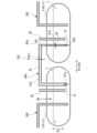
図7に示すように、タンク設備10Cは、複数のタンク11と、積込配管20Cと、揚荷配管30と、移送配管40Cと、を少なくとも備えている。
積込配管20Cは、陸上の液化二酸化炭素供給施設等、船外から供給される液化二酸化炭素Lをタンク11内に積み込む。この第三実施形態の積込配管20Cは、複数のタンク11のそれぞれに一つずつ設けられている。
Third Embodiment
Next, a third embodiment of the floating body and the method for loading liquefied carbon dioxide according to the present disclosure will be described. In the third embodiment described below, the same parts as those in the first and second embodiments described above are denoted by the same reference numerals, and duplicated explanations will be omitted.
As shown in FIG. 7, the tank facility 10C includes at least a plurality of
The
揚荷配管30は、各タンク11内の液化二酸化炭素Lを、陸上の液化二酸化炭素供給施設等、船外に送出する。揚荷配管30は、タンク11の外部からタンク11の頂部を貫通し、タンク11の内部に延びている。揚荷配管30の先端部は、タンク11内の下部に配置されている。揚荷配管30の先端部には、ポンプ31が備えられている。ポンプ31は、タンク11内の液化二酸化炭素Lを吸い込む。揚荷配管30は、ポンプ31で吸い込んだ液化二酸化炭素Lを、タンク11外(船外)に送出する。この第三実施形態の揚荷配管30も、積込配管20Cと同様に、複数のタンク11のそれぞれに一つずつ設けられている。なお、以下の説明においては、複数のタンク11として第一のタンク11Pと第二のタンク11Qとの二つを備える場合を一例にして説明する。
The
移送配管40Cは、第一のタンク11Pと第二のタンク11Qとの間に跨がるように配置されている。移送配管40Cは、第一のタンク11P内と第二のタンク11Q内とを連通させている。この移送配管40Cにより、第一のタンク11Pから第二のタンク11Qに液化二酸化炭素Lを移送することが可能になっている。移送配管40Cは、第一移送配管41と、第二移送配管42と、を備えている。
The
第一移送配管41は、第一のタンク11P側に配置されている。この第一移送配管41の第一端41aは、第一のタンク11P内に挿入され、第一のタンク11P内の下部で下方を向いて開口している。第一移送配管41は、第一端41aから上方に向かって延びて、第一のタンク11Pの外部に至っている。第一移送配管41のうち第一のタンク11Pと第二のタンク11Qとの双方の外部に配置されている中間部41bは、第一のタンク11P及び第二のタンク11Qの上方で水平方向に延びている。上記第一移送配管41は、第一の内径D11を有している。
The
第二移送配管42の一端42aは、第一移送配管41に接続されている。第二移送配管42は、第二のタンク11Qの頂部を貫通して第二のタンク11Qの外部から内部に延びている。第二移送配管42は、第二のタンク11Q内で上下方向Dvに延びている。第二移送配管42の他端42bは、第二のタンク11Q内の下部で下方を向いて開口している。第二移送配管42は、第一の内径D11よりも小さい第二の内径D12を有している。この第三実施形態において、第二移送配管42は、その全長にわたって第二の内径D12を有している。第二移送配管42は、他端42b側の一定長のみを、第二の内径D12で形成し、一端42a側は、第一移送配管41と同じ第一の内径D11で形成してもよい。
One
移送配管40Cには、開閉弁45が設けられている。開閉弁45は、移送配管40Cを開閉する。開閉弁45は、通常時は閉状態とされている。
各タンク11(第一のタンク11P、第二のタンク11Q)において、タンク11内の液化二酸化炭素Lを揚荷する場合は、各タンク11内で、揚荷配管30に設けられたポンプ31を作動させる。すると、ポンプ31によって、タンク11内の液化二酸化炭素Lが吸い込まれ、揚荷配管30を通して船外に送出される。
The
When the liquefied carbon dioxide L in each tank 11 (
第一のタンク11Pのポンプ31が、故障等によって所要の機能を発揮できない状態となった場合、開閉弁45を開状態とする。すると、移送配管40Cを通して、第一のタンク11P内と第二のタンク11Q内とが連通する。この状態で、第一のタンク11P以外の他のタンク(例えば、第二のタンク11Q)内の加圧用ガスGp(例えばボイルオフガス)を、不図示の加圧用ガス管を通して第一のタンク11Pに挿入する。すると、第一のタンク11P内の気相の圧力が高まり、第一のタンク11P内の液化二酸化炭素Lが加圧される。これにより、第一のタンク11P内の気相の圧力と第二のタンク11Q内の気相の圧力との圧力差により、第一のタンク11P内の液化二酸化炭素Lが、移送配管40C(第一移送配管41、第二移送配管42)を通して、第二のタンク11Q内に送り込まれる。第一のタンク11Pから第二のタンク11Q内に移送された液化二酸化炭素Lは、第二のタンク11Qの揚荷配管30に設けられたポンプ31により、揚荷配管30を通して船外に送出される。
When the
(作用効果)
上述したような船舶1では、液化二酸化炭素Lが、第一移送配管41から第二移送配管42を通して第一のタンク11Pから第二のタンク11Qに移送される。第二のタンク11Qに移送された液化二酸化炭素Lは、第二のタンク11Qの揚荷配管30を通して外部に送り出される。このようにして、第一のタンク11Pの揚荷配管30で揚荷作業が行えない場合であっても、第一のタンク11P内の液化二酸化炭素Lを、第二のタンク11Qを介して外部に揚荷することができる。
そして、第二移送配管42の第二の内径D12が、第一移送配管41の第一の内径D11よりも小さいため、第二移送配管42では、第一移送配管41よりも、圧力損失ΔPが大きくなり、移送配管40Cを流通する液化二酸化炭素Lの圧力を圧力損失ΔPの分だけ高めることができる。そのため、移送配管40Cの配管頂部における液化二酸化炭素Lの圧力が高められ、液化二酸化炭素Lの圧力が三重点圧力に近づくことを抑えることができる。これにより、移送配管40C内で液化二酸化炭素Lが凝固してドライアイスが生成されることが抑えられる。その結果、移送配管40Cにより第一のタンク11Pから第二のタンク11Qに液化二酸化炭素Lを移送する場合においても、移送配管40C内のドライアイス生成を抑え、移送作業及び揚荷作業を円滑に行うことが可能となる。
(Action and Effect)
In the ship 1 as described above, the liquefied carbon dioxide L is transferred from the
Since the second inner diameter D12 of the
<第四実施形態>
次に、本開示に係る浮体、液化二酸化炭素の揚荷方法の第四の実施形態について説明する。以下に説明する第四の実施形態においては、第三実施形態に対し、第三移送配管43を備える構成のみが異なるので、第三実施形態と同一部分に同一符号を付して説明するとともに、重複説明を省略する。
<Fourth embodiment>
Next, a fourth embodiment of the floating body and the method for unloading liquefied carbon dioxide according to the present disclosure will be described. The fourth embodiment described below differs from the third embodiment only in that it includes a
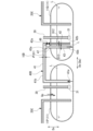
図8に示すように、タンク設備10Dは、複数のタンク11と、複数の積込配管20Cと、複数の揚荷配管30と、移送配管40Dと、を少なくとも備えている。なお、この第四実施形態においても、タンク11が二つ(第一のタンク11P及び第二のタンク11Q)の場合を一例にして説明する。
As shown in FIG. 8, the
移送配管40Dは、第一のタンク11Pと第二のタンク11Qとの間に跨がるように配置されている。移送配管40Dは、第一のタンク11Pから第二のタンク11Qに液化二酸化炭素Lを移送する。移送配管40Dは、第一移送配管41と、第二移送配管42と、第三移送配管43と、を備えている。
The
第一移送配管41は、第一のタンク11P側に配置されている。この第一移送配管41の第一端41aは、第一のタンク11P内に挿入され、第一のタンク11P内の下部で下方を向いて開口している。第一移送配管41のうち、第一のタンク11Pと第二のタンク11Qとの双方の外部に配置されている中間部41bは、第一のタンク11P及び第二のタンク11Qの上方で水平方向に延びている。上記第一移送配管41は、第一の内径D11を有している。
The
第二移送配管42の一端42a(言い換えれば、上下方向Dvにおける上側端)は、第一移送配管41に接続されている。第二移送配管42は、第二のタンク11Qの頂部を貫通して第二のタンク11Qの外部から内部に延びている。第二移送配管42は、第二のタンク11Q内で上下方向Dvに延びている。第二移送配管42の他端42bは、第二のタンク11Q内の下部で下方を向いて開口している。第二移送配管42は、第一の内径D11よりも小さい第二の内径D12を有している。
One
第三移送配管43の基端43a(言い換えれば、上下方向Dvにおける上側端)は、第一移送配管41に接続されている。第三移送配管43は、第二のタンク11Qの頂部を貫通して第二のタンク11Qの外部から内部に延びている。第三移送配管43は、第二のタンク11Q内で上下方向Dvに延びている。第三移送配管43の先端43b(言い換えれば、上下方向Dvにおける下側端)は、タンク11内の下部で下方を向いて開口している。第三移送配管43は、第二の内径D2よりも大きい第三の内径D13を有している。なお、第三の内径D13は、第一移送配管41の第一の内径D11と同一であってもよい。
The
第二移送配管42には、開閉弁46が設けられている。開閉弁46は、第二移送配管42を開閉する。第三移送配管43には、開閉弁47が設けられている。開閉弁47は、第三移送配管43を開閉する。開閉弁46、47は、通常時は閉状態とされている。
各タンク(第一のタンク11P、第二のタンク11Q)において、タンク11内の液化二酸化炭素Lを揚荷する場合は、各タンク11内で、揚荷配管30に設けられたポンプ31を作動させる。すると、ポンプ31によって、タンク11内の液化二酸化炭素Lが吸い込まれ、揚荷配管30を通して船外に送出される。
An on-off
When the liquefied carbon dioxide L in each tank (
(液化二酸化炭素の揚荷方法の手順)
第一のタンク11Pのポンプ31が、故障等によって所要の機能を発揮できない状態となった場合、以下の液化二酸化炭素の揚荷方法S11を実行する。
図9に示すように、本開示の実施形態に係る液化二酸化炭素の揚荷方法S11は、第二移送配管42を通して液化二酸化炭素Lを移送する工程S12と、第三移送配管43を通して液化二酸化炭素Lを移送する工程S13と、液化二酸化炭素Lを外部に送り出す工程S14と、を含んでいる。
(Procedure for unloading liquefied carbon dioxide)
When the
As shown in Figure 9, a method S11 for unloading liquefied carbon dioxide according to an embodiment of the present disclosure includes a step S12 of transporting liquefied carbon dioxide L through a second transport piping 42, a step S13 of transporting the liquefied carbon dioxide L through a third transport piping 43, and a step S14 of sending the liquefied carbon dioxide L to the outside.
図10に示すように、第二移送配管42を通して液化二酸化炭素Lを移送する工程S12では、開閉弁46を開状態、開閉弁47を閉状態とする。これにより、第一移送配管41と第二移送配管42とが連通された状態になる。この状態で、加圧用ガスGpとして、第一のタンク11P以外の他のタンク(例えば、第二のタンク11Q)内のボイルオフガスを、不図示の加圧用ガス管を通して第一のタンク11Pに導入する。すると、第一のタンク11P内の気相の圧力が高まり、第一のタンク11P内の気相の圧力と、第二のタンク11Q内の気相の圧力との圧力差が生じる。これにより、第一のタンク11P内の液化二酸化炭素Lが、第一移送配管41、第二移送配管42を通して、第二のタンク11Q内に送り込まれる。このとき、第二移送配管42の第二の内径D2は、第一移送配管41の第一の内径D1よりも小さい。そのため、第二移送配管42における圧力損失ΔPが大きくなり、移送配管40D内でドライアイスが生成されることを抑えつつ、液化二酸化炭素Lの積込が行われる。
10, in step S12 of transferring the liquefied carbon dioxide L through the
図11に示すように、第二のタンク11Q内の液化二酸化炭素Lの液位が、予め定めた規定液位に到達したら、第三移送配管43を通して液化二酸化炭素Lを移送する工程S13に移行する。これには、開閉弁46を閉状態、開閉弁47を開状態にする。これにより、第一移送配管41と第三移送配管43とが連通された状態になる。
上記のようにタンク11内の液化二酸化炭素Lの液位が上がり、規定液位に達すると、第二のタンク11Q内の液化二酸化炭素Lと移送配管40Dの配管頂部との差圧が小さくなる。これにより、移送配管40Dの配管頂部で液化二酸化炭素Lが凝固しにくい状態となる。
このような状態で工程S13が実施される。この工程S13では、上記と同様に加圧用ガスGpを用い、第一移送配管41から第三移送配管43を通して、第一のタンク11P内の液化二酸化炭素Lを第二のタンク11Q内に移送する。このとき、第三移送配管43の第三の内径D3は、第二移送配管42の第二の内径D2よりも大きい。そのため、工程S12に比較し、第三移送配管43を通して第二のタンク11Q内に供給する液化二酸化炭素Lの流量を増大させることができる。
11, when the liquid level of the liquefied carbon dioxide L in the
As described above, when the liquid level of the liquefied carbon dioxide L in the
In this state, step S13 is carried out. In this step S13, the pressurizing gas Gp is used in the same manner as described above, and the liquefied carbon dioxide L in the
液化二酸化炭素Lを第二のタンク11Qの外部に送り出す工程S14では、第二のタンク11Q内の液化二酸化炭素Lを、揚荷配管30によりタンク11の外部に送り出す。このような工程S14は、上記の工程S12、S13と並行して実施しても良い。
In step S14 of sending the liquefied carbon dioxide L to the outside of the
(作用効果)
上述したような船舶1、液化二酸化炭素Lの揚荷方法S11では、タンク11内の液化二酸化炭素Lの液位が低いときには、第二移送配管42を通して液化二酸化炭素Lを第一のタンク11Pから第二のタンク11Qに移送することで、移送配管40D内で液化二酸化炭素Lが凝固してドライアイスが生成されることが抑えられる。また、第二のタンク11Q内の液化二酸化炭素Lの液位が上がり、第二のタンク11Q内の液化二酸化炭素Lと移送配管40Dの配管頂部との差圧が小さくなり、配管頂部で液化二酸化炭素Lが凝固しにくい状態となった場合には、第三移送配管43を通して液化二酸化炭素Lを第一のタンク11Pから第二のタンク11Qに移送する。これにより、液化二酸化炭素Lの移送を短時間で行うことができる。その結果、移送配管40Dにより第一のタンク11Pから第二のタンク11Qに液化二酸化炭素Lを移送する場合においても、移送配管40D内のドライアイス生成を抑え、移送作業及び揚荷作業を円滑に行うことが可能となる。
(Action and Effect)
In the ship 1 and the method S11 for unloading liquefied carbon dioxide L as described above, when the liquid level of the liquefied carbon dioxide L in the
(その他の実施形態)
以上、本開示の実施の形態について図面を参照して詳述したが、具体的な構成はこの実施の形態に限られるものではなく、本開示の要旨を逸脱しない範囲の設計変更等も含まれる。
なお、上記各実施形態では、二つのタンク11を備える構成としたが、タンク11の個数や配置はこれに限られない。三つ以上のタンク11を備えていてもよい。また、上記各実施形態では、複数のタンク11を船首尾方向Daに並べて配置する場合を例示したが、タンク11は、船幅方向(言い換えれば、左右舷方向)に並べて配置してもよい。
Other Embodiments
Although the embodiments of the present disclosure have been described in detail above with reference to the drawings, the specific configuration is not limited to this embodiment, and design changes and the like that do not deviate from the gist of the present disclosure are also included.
In each of the above embodiments, the vessel is configured to include two
また、上記各実施形態では、浮体として船舶1を例示したが、これに限られない。浮体は、推進機構を備えない洋上浮体設備であってもよい。 In addition, in each of the above embodiments, a ship 1 is given as an example of a floating body, but this is not limited thereto. The floating body may be an offshore floating facility that does not have a propulsion mechanism.
<付記>
各実施形態に記載の浮体1、液化二酸化炭素Lの積込方法、液化二酸化炭素Lの揚荷方法は、例えば以下のように把握される。
<Additional Notes>
The floating body 1, the method of loading liquefied carbon dioxide L, and the method of unloading liquefied carbon dioxide L described in each embodiment can be understood, for example, as follows.
(1)第1の態様に係る浮体1は、浮体本体2と、前記浮体本体2に配置され、液化二酸化炭素Lを貯留可能なタンク11と、外部から供給される液化二酸化炭素Lを前記タンク11内に放出する積込配管20A、20Bと、を備え、前記積込配管20A、20Bは、前記タンク11の外部に配置され、第一の内径D1を有した第一積込配管21と、一端22aが前記第一積込配管21に接続されるとともに、他端22bが前記タンク11内で開口し、前記第一の内径D1よりも小さい第二の内径D2を有した第二積込配管22と、を備える。
浮体1の例としては、船舶や洋上浮体設備が挙げられる。浮体本体2の例としては、船体や洋上浮体設備の浮体本体2が挙げられる。
(1) A float 1 in a first aspect comprises a
Examples of the floating body 1 include a ship and an offshore floating facility. Examples of the floating body
この浮体1では、液化二酸化炭素Lが、第一積込配管21から第二積込配管22を通してタンク11内に積み込まれる。第二積込配管22の第二の内径D2は、第一積込配管21の第一の内径D1よりも小さい。そのため、第二積込配管22では、第一積込配管21よりも、圧力損失ΔPが大きくなる。これにより、積込配管20A、20Bを流通する液化二酸化炭素Lの圧力が圧力損失ΔPの分だけ高められる。積込配管20A、20Bの配管頂部における液化二酸化炭素Lの圧力が高められることで、液化二酸化炭素Lの圧力が三重点圧力に近づくことが抑えられる。これにより、積込配管20A、20B内で液化二酸化炭素Lが凝固してドライアイスが生成されることが抑えられる。その結果、タンク11内に液化二酸化炭素Lを収容する場合において、積込配管20A、20B内のドライアイス生成を抑え、積込作業を円滑に行うことが可能となる。
In this floating body 1, liquefied carbon dioxide L is loaded into the
(2)第2の態様に係る浮体1は、(1)の浮体1であって、前記積込配管20Bは、基端23aが前記第一積込配管21に接続され、先端23bが前記タンク11内で開口し、前記第二の内径D2よりも大きい第三の内径D3を有した第三積込配管23、を更に備える。
(2) The float 1 according to the second aspect is the float 1 of (1), and the
これにより、第二積込配管22よりも大きな第三の内径D3を有した第三積込配管23を通して液化二酸化炭素Lをタンク11内に積み込めば、液化二酸化炭素Lの積込を短時間で行うことができる。
As a result, if the liquefied carbon dioxide L is loaded into the
(3)第3の態様に係る浮体1は、浮体本体2と、前記浮体本体2に配置され、液化二酸化炭素Lを貯留可能な複数のタンク11と、複数の前記タンク11のそれぞれに設けられて、前記タンク11内の液化二酸化炭素Lを前記浮体本体2の外部に送り出す揚荷配管30と、前記複数のタンク11をなす第一のタンク11Pと第二のタンク11Qとの間に跨がるように配置され、前記第一のタンク11P内と前記第二のタンク11Q内とを連通させる移送配管40C,40Dと、を備え、前記移送配管40C,40Dは、前記第一のタンク11P側に配置され、第一の内径D11を有した第一移送配管41と、一端42aが前記第一移送配管41に接続されるとともに、他端42bが前記第二のタンク11Q内で開口し、前記第一の内径D11よりも小さい第二の内径D12を有した第二移送配管42と、を備える。
(3) The float 1 according to the third aspect comprises a
これにより、移送配管40C、40Dを通して、第一のタンク11Pから第二のタンク11Qに液化二酸化炭素Lを移送することができる。第二のタンク11Qに移送された液化二酸化炭素Lは、第二のタンク11Qの揚荷配管30を通して外部に送り出される。このようにして、第一のタンク11Pの揚荷配管30で揚荷作業が行えない場合であっても、第一のタンク11P内の液化二酸化炭素Lを、第二のタンク11Qを介して外部に揚荷することができる。
第二移送配管42の第二の内径D12は、第一移送配管41の第一の内径D11よりも小さい。そのため、第二移送配管42では、第一移送配管41よりも、圧力損失ΔPが大きくなる。これにより、移送配管40C、40Dを流通する液化二酸化炭素Lの圧力が圧力損失ΔPの分だけ高められる。移送配管40C、40Dの配管頂部における液化二酸化炭素Lの圧力が高められることで、液化二酸化炭素Lの圧力が三重点圧力に近づくことが抑えられる。これにより、移送配管40C、40D内で液化二酸化炭素Lが凝固してドライアイスが生成されることが抑えられる。その結果、タンク11内に液化二酸化炭素Lを収容する場合において、移送配管40C、40D内のドライアイス生成を抑え、移送作業及び揚荷作業を円滑に行うことが可能となる。
This allows the liquefied carbon dioxide L to be transferred from the
The second inner diameter D12 of the
(4)第4の態様に係る浮体1は、(3)の浮体1であって、前記移送配管40Dは、基端43aが前記第一移送配管41に接続され、先端43bが前記第二のタンク11Q内で開口し、前記第二の内径D12よりも大きい第三の内径D13を有した第三移送配管43、を更に備える。
(4) The float 1 according to the fourth aspect is the float 1 according to (3), and the
これにより、第二移送配管42よりも大きな第三の内径D13を有した第三移送配管43を通して液化二酸化炭素Lを移送すれば、液化二酸化炭素Lの移送を短時間で行うことができる。
As a result, by transporting the liquefied carbon dioxide L through the
(5)第5の態様に係る液化二酸化炭素Lの積込方法S1は、(2)の浮体1における、液化二酸化炭素Lの積込方法S1であって、前記第一積込配管21から前記第二積込配管22を通して前記タンク11内に液化二酸化炭素Lを積み込む工程S2と、前記タンク11内の液化二酸化炭素Lの液位が定められた液位に到達したら、前記第一積込配管21から前記第三積込配管23を通して前記タンク11内に液化二酸化炭素Lを積み込む工程S3と、を含む。
(5) The method S1 for loading liquefied carbon dioxide L according to the fifth aspect is a method S1 for loading liquefied carbon dioxide L in the floating body 1 of (2), and includes a step S2 of loading liquefied carbon dioxide L from the
これにより、タンク11内の液化二酸化炭素Lの液位が低いときには、第一積込配管21を通して液化二酸化炭素Lをタンク11に積み込むことで、積込配管20B内で液化二酸化炭素Lが凝固してドライアイスが生成されることが抑えられる。また、タンク11内の液化二酸化炭素Lの液位が上がり、タンク11内の液化二酸化炭素Lと積込配管20Bの配管頂部との差圧が小さくなり、配管頂部で液化二酸化炭素Lが凝固しにくい状態となった場合には、第三積込配管23を通して液化二酸化炭素Lをタンク11に積み込む。これにより、液化二酸化炭素Lの積込を短時間で行うことができる。
As a result, when the liquid level of liquefied carbon dioxide L in the
(6)第6の態様に係る液化二酸化炭素Lの揚荷方法S11は、(4)の浮体1における、液化二酸化炭素Lの揚荷方法S11であって、前記第一のタンク11P内を加圧することで、前記第一のタンク11P内の液化二酸化炭素Lを、前記第一移送配管41から前記第二移送配管42を通して前記第二のタンク11Q内に移送する工程S12と、前記第二のタンク11Q内の液化二酸化炭素Lの液位が定められた液位に到達したら、前記第一のタンク11P内の液化二酸化炭素Lを、前記第一移送配管41から前記第三移送配管43を通して前記第二のタンク11Q内に移送する工程S13と、前記第二のタンク11Q内の前記液化二酸化炭素Lを、前記揚荷配管30により前記第二のタンク11Qの外部に送り出す工程S14と、を含む。
(6) The method S11 for unloading liquefied carbon dioxide L according to the sixth aspect is the method S11 for unloading liquefied carbon dioxide L in the floating body 1 of (4), and includes a step S12 of pressurizing the
これにより、第二のタンク11Q内の液化二酸化炭素Lの液位が低いときには、第二移送配管42を通して液化二酸化炭素Lを第一のタンク11Pから第二のタンク11Qに移送することで、移送配管40D内で液化二酸化炭素Lが凝固してドライアイスが生成されることが抑えられる。また、第二のタンク11Q内の液化二酸化炭素Lの液位が上がり、第二のタンク11Q内の液化二酸化炭素Lと移送配管40Dの配管頂部との差圧が小さくなり、配管頂部で液化二酸化炭素Lが凝固しにくい状態となった場合には、第三移送配管43を通して液化二酸化炭素Lを第一のタンク11Pから第二のタンク11Qに移送する。これにより、液化二酸化炭素Lの移送を短時間で行うことができる。
As a result, when the liquid level of the liquefied carbon dioxide L in the
1…船舶(浮体)
2…船体(浮体本体)
2a…船首
2b…船尾
3A、3B…舷側
5…上甲板
7…上部構造
8…貨物搭載区画
10A~10D…タンク設備
11…タンク
11P…第一のタンク
11Q…第二のタンク
12…筒状部
13…端部球状部
20A~20C…積込配管
21…第一積込配管
22…第二積込配管
22a…一端
22b…他端
23…第三積込配管
23a…基端
23b…先端
24、25…開閉弁
30…揚荷配管
31…ポンプ
40C,40D…移送配管
41…第一移送配管
41a…第一端
41b…中間部
42…第二移送配管
42a…一端
42b…他端
43…第三移送配管
43a…基端
43b…先端
45~47…開閉弁
Gp…加圧用ガス
L…液化二酸化炭素
1... Ship (floating body)
2...Hull (floating body)
2a...bow 2b...stern 3A, 3B...
Claims (8)
前記浮体本体に配置され、液化二酸化炭素を貯留可能なタンクと、
外部から供給される液化二酸化炭素を前記タンク内に放出する積込配管と、を備え、
前記積込配管は、
前記タンクの外部に配置されて前記タンクの上方で水平方向に延び、第一の内径を有した第一積込配管と、
一端が前記第一積込配管に接続されて前記タンクの外部から内部に延びるとともに、前記タンク内で上下方向に延び、上下方向における下側端である他端が前記タンク内で開口し、前記第一の内径よりも小さい第二の内径を有した第二積込配管と、
を備える浮体。 A floating body;
A tank arranged on the floating body and capable of storing liquefied carbon dioxide;
a loading pipe for discharging liquefied carbon dioxide supplied from an outside into the tank;
The loading pipe is
a first loading pipe disposed outside the tank, extending horizontally above the tank, the first loading pipe having a first inner diameter;
a second loading pipe having one end connected to the first loading pipe and extending from the outside to the inside of the tank, extending in a vertical direction within the tank, and having a second inner diameter smaller than the first inner diameter, the other end being a lower end in the vertical direction and opening within the tank;
A floating body comprising:
基端が前記第一積込配管に接続され、先端が前記タンク内で開口し、前記第二の内径よりも大きい第三の内径を有した第三積込配管、を更に備える
請求項1に記載の浮体。 The loading pipe is
The floating body according to claim 1 , further comprising: a third loading pipe having a base end connected to the first loading pipe, a tip end opening within the tank, and a third inner diameter larger than the second inner diameter.
前記浮体本体に配置され、液化二酸化炭素を貯留可能な複数のタンクと、
複数の前記タンクのそれぞれに設けられて、前記タンク内の液化二酸化炭素を前記浮体本体の外部に送り出す揚荷配管と、
前記複数のタンクをなす第一のタンクと第二のタンクとの間に跨がるように配置され、前記第一のタンク内と前記第二のタンク内とを連通させる移送配管と、を備え、
前記移送配管は、
前記第一のタンク側に配置され、第一の内径を有した第一移送配管と、
一端が前記第一移送配管に接続されるとともに、他端が前記第二のタンク内で開口し、前記第一の内径よりも小さい第二の内径を有した第二移送配管と、
を備え、
前記第一移送配管は、前記第一のタンクと前記第二のタンクとの双方の外部に配置されて、前記第一のタンク及び前記第二のタンクの上方で水平方向に延びる中間部を備え、
前記第二移送配管は、前記第二のタンクの外部から内部に延びるとともに、前記第二のタンク内で上下方向に延びて、前記第二移送配管の下側端が前記他端として前記第二のタンク内で開口している
浮体。 A floating body;
A plurality of tanks arranged on the floating body and capable of storing liquefied carbon dioxide;
A lifting pipe provided in each of the plurality of tanks for sending the liquefied carbon dioxide in the tank to the outside of the floating body;
a transfer pipe disposed between a first tank and a second tank of the plurality of tanks, the transfer pipe connecting an inside of the first tank and an inside of the second tank;
The transfer piping includes:
a first transfer pipe disposed on the first tank side and having a first inner diameter;
a second transfer pipe having one end connected to the first transfer pipe and the other end opening into the second tank, the second transfer pipe having a second inner diameter smaller than the first inner diameter;
Equipped with
the first transfer pipe is disposed outside both the first tank and the second tank and has an intermediate portion extending horizontally above the first tank and the second tank;
The second transfer piping extends from the outside to the inside of the second tank and extends in the vertical direction within the second tank , with the lower end of the second transfer piping opening within the second tank as the other end .
基端が前記第一移送配管に接続され、先端が前記第二のタンク内で開口し、前記第二の内径よりも大きい第三の内径を有した第三移送配管、を更に備える
請求項3に記載の浮体。 The transfer piping includes:
The floating body according to claim 3 , further comprising a third transfer pipe having a base end connected to the first transfer pipe, a tip end opening within the second tank, and a third inner diameter larger than the second inner diameter.
前記第一積込配管から前記第二積込配管を通して前記タンク内に液化二酸化炭素を積み込む工程と、
前記タンク内の液化二酸化炭素の液位が定められた液位に到達したら、前記第一積込配管から前記第三積込配管を通して前記タンク内に液化二酸化炭素を積み込む工程と、を含む
液化二酸化炭素の積込方法。 A method for loading liquefied carbon dioxide into a floating body according to claim 2, comprising the steps of:
Loading liquefied carbon dioxide into the tank through the first loading pipe and the second loading pipe;
When the liquid level of the liquefied carbon dioxide in the tank reaches a predetermined liquid level, loading the liquefied carbon dioxide into the tank from the first loading pipe through the third loading pipe.
前記第一のタンク内を加圧することで、前記第一のタンク内の液化二酸化炭素を、前記第一移送配管から前記第二移送配管を通して前記第二のタンク内に移送する工程と、
前記第二のタンク内の液化二酸化炭素の液位が定められた液位に到達したら、前記第一のタンク内の液化二酸化炭素を、前記第一移送配管から前記第三移送配管を通して前記第二のタンク内に移送する工程と、
前記第二のタンク内の前記液化二酸化炭素を、前記揚荷配管により前記第二のタンクの外部に送り出す工程と、を含む
液化二酸化炭素の揚荷方法。 A method for unloading liquefied carbon dioxide in a floating body according to claim 4, comprising the steps of:
A step of pressurizing the first tank to transfer liquefied carbon dioxide in the first tank from the first transfer pipe through the second transfer pipe into the second tank;
When the liquid level of the liquefied carbon dioxide in the second tank reaches a predetermined liquid level, the liquefied carbon dioxide in the first tank is transferred from the first transfer pipe to the second tank through the third transfer pipe;
and sending the liquefied carbon dioxide in the second tank to the outside of the second tank through the lifting piping.
前記浮体本体に配置され、液化二酸化炭素を貯留可能なタンクと、
外部から供給される液化二酸化炭素を前記タンク内に放出する積込配管と、を備え、
前記積込配管は、
前記タンクの外部に配置され、第一の内径を有した第一積込配管と、
一端が前記第一積込配管に接続されるとともに、他端が前記タンク内で開口し、前記第一の内径よりも小さい第二の内径を有した第二積込配管と、
を備え、
前記積込配管は、
基端が前記第一積込配管に接続され、先端が前記タンク内で開口し、前記第二の内径よりも大きい第三の内径を有した第三積込配管、を更に備える
浮体。 A floating body;
A tank arranged on the floating body and capable of storing liquefied carbon dioxide;
a loading pipe for discharging liquefied carbon dioxide supplied from an outside into the tank;
The loading pipe is
a first loading pipe disposed outside the tank, the first loading pipe having a first inner diameter;
a second loading pipe having one end connected to the first loading pipe and the other end opening into the tank and having a second inner diameter smaller than the first inner diameter;
Equipped with
The loading pipe is
The float further comprises a third loading pipe having a base end connected to the first loading pipe, a tip end opening within the tank, and a third inner diameter larger than the second inner diameter.
前記浮体本体に配置され、液化二酸化炭素を貯留可能な複数のタンクと、
複数の前記タンクのそれぞれに設けられて、前記タンク内の液化二酸化炭素を前記浮体本体の外部に送り出す揚荷配管と、
前記複数のタンクをなす第一のタンクと第二のタンクとの間に跨がるように配置され、前記第一のタンク内と前記第二のタンク内とを連通させる移送配管と、を備え、
前記移送配管は、
前記第一のタンク側に配置され、第一の内径を有した第一移送配管と、
一端が前記第一移送配管に接続されるとともに、他端が前記第二のタンク内で開口し、前記第一の内径よりも小さい第二の内径を有した第二移送配管と、
を備え、
前記移送配管は、
基端が前記第一移送配管に接続され、先端が前記第二のタンク内で開口し、前記第二の内径よりも大きい第三の内径を有した第三移送配管、を更に備える
浮体。 A floating body;
A plurality of tanks arranged on the floating body and capable of storing liquefied carbon dioxide;
A lifting pipe provided in each of the plurality of tanks for sending the liquefied carbon dioxide in the tank to the outside of the floating body;
a transfer pipe disposed between a first tank and a second tank of the plurality of tanks, the transfer pipe connecting an inside of the first tank and an inside of the second tank;
The transfer piping includes:
a first transfer pipe disposed on the first tank side and having a first inner diameter;
a second transfer pipe having one end connected to the first transfer pipe and the other end opening into the second tank, the second transfer pipe having a second inner diameter smaller than the first inner diameter;
Equipped with
The transfer piping includes:
The float further comprises a third transfer pipe having a base end connected to the first transfer pipe, a tip end opening within the second tank, and a third inner diameter larger than the second inner diameter.
Priority Applications (6)
| Application Number | Priority Date | Filing Date | Title |
|---|---|---|---|
| JP2020180559A JP7561574B2 (en) | 2020-10-28 | 2020-10-28 | Floating body, method for loading liquefied carbon dioxide, and method for unloading liquefied carbon dioxide |
| AU2021367440A AU2021367440B2 (en) | 2020-10-28 | 2021-10-28 | Floating Structure, Method For Loading Liquefied Carbon Dioxide, And Method For Unloading Liquefied Carbon Dioxide |
| PCT/JP2021/039910 WO2022092236A1 (en) | 2020-10-28 | 2021-10-28 | Floating body, method for loading liquefied carbon dioxide, and method for unloading liquefied carbon dioxide |
| EP21886353.8A EP4194329A4 (en) | 2020-10-28 | 2021-10-28 | FLOAT BODY, METHOD FOR LOADING LIQUEFIED CARBON DIOXIDE AND METHOD FOR DISCHARGING LIQUEFIED CARBON DIOXIDE |
| KR1020237007489A KR20230044005A (en) | 2020-10-28 | 2021-10-28 | Floating body, loading method of liquefied carbon dioxide, and unloading method of liquefied carbon dioxide |
| CN202180054464.9A CN116075464A (en) | 2020-10-28 | 2021-10-28 | Floating body, loading method of liquefied carbon dioxide and unloading method of liquefied carbon dioxide |
Applications Claiming Priority (1)
| Application Number | Priority Date | Filing Date | Title |
|---|---|---|---|
| JP2020180559A JP7561574B2 (en) | 2020-10-28 | 2020-10-28 | Floating body, method for loading liquefied carbon dioxide, and method for unloading liquefied carbon dioxide |
Publications (2)
| Publication Number | Publication Date |
|---|---|
| JP2022071534A JP2022071534A (en) | 2022-05-16 |
| JP7561574B2 true JP7561574B2 (en) | 2024-10-04 |
Family
ID=81382634
Family Applications (1)
| Application Number | Title | Priority Date | Filing Date |
|---|---|---|---|
| JP2020180559A Active JP7561574B2 (en) | 2020-10-28 | 2020-10-28 | Floating body, method for loading liquefied carbon dioxide, and method for unloading liquefied carbon dioxide |
Country Status (6)
| Country | Link |
|---|---|
| EP (1) | EP4194329A4 (en) |
| JP (1) | JP7561574B2 (en) |
| KR (1) | KR20230044005A (en) |
| CN (1) | CN116075464A (en) |
| AU (1) | AU2021367440B2 (en) |
| WO (1) | WO2022092236A1 (en) |
Families Citing this family (3)
| Publication number | Priority date | Publication date | Assignee | Title |
|---|---|---|---|---|
| JP7595612B2 (en) * | 2022-05-13 | 2024-12-06 | 三菱重工業株式会社 | Floating body, method for loading liquefied carbon dioxide |
| JP7588621B2 (en) * | 2022-06-15 | 2024-11-22 | 三菱重工業株式会社 | Liquefied carbon dioxide discharge facility, floating body, and liquefied carbon dioxide discharge method |
| KR102884343B1 (en) * | 2023-05-02 | 2025-11-13 | 한화오션 주식회사 | Liquefied carbon dioxide unloading system and liquefied carbon dioxide unloading method preventing dry ice generation |
Citations (3)
| Publication number | Priority date | Publication date | Assignee | Title |
|---|---|---|---|---|
| JP2009279979A (en) | 2008-05-20 | 2009-12-03 | Shin Kurushima Dockyard Co Ltd | Cargo oil pipe device |
| JP2011513140A (en) | 2008-03-28 | 2011-04-28 | 三星重工業株式会社 | LNG carrier with liquefied natural gas (LNG) loading and unloading system |
| JP2019512072A (en) | 2016-02-29 | 2019-05-09 | テーゲーエー、マリン、ガス、エンジニヤリング、ゲーエムベーハー | Operating method of liquefied gas storage tank and liquefied gas storage tank for receiving LNG and boil-off gas |
Family Cites Families (7)
| Publication number | Priority date | Publication date | Assignee | Title |
|---|---|---|---|---|
| US3848559A (en) * | 1973-01-15 | 1974-11-19 | Exxon Research Engineering Co | Centralized cargo handling system for cryogenic vessels |
| WO2008097099A1 (en) * | 2007-02-08 | 2008-08-14 | Knutsen Oas Shipping As | Method and device for transport of gas |
| KR101599297B1 (en) * | 2009-09-09 | 2016-03-04 | 대우조선해양 주식회사 | Floating structure with a transfer pipe line |
| KR101497420B1 (en) * | 2013-07-05 | 2015-03-03 | 삼성중공업 주식회사 | LNG transportation Apparatus for reducing Boil-Off Gas |
| KR101408347B1 (en) * | 2013-09-06 | 2014-06-17 | 대우조선해양 주식회사 | Vaporization reducing system and method of liquid cargo for a ship |
| CN108027108B (en) | 2015-09-28 | 2019-09-10 | 瓦锡兰芬兰有限公司 | Fuel tank installations for ships at sea |
| JP7093325B2 (en) | 2019-04-24 | 2022-06-29 | 三菱重工エンジン&ターボチャージャ株式会社 | Playback control device |
-
2020
- 2020-10-28 JP JP2020180559A patent/JP7561574B2/en active Active
-
2021
- 2021-10-28 AU AU2021367440A patent/AU2021367440B2/en active Active
- 2021-10-28 EP EP21886353.8A patent/EP4194329A4/en active Pending
- 2021-10-28 KR KR1020237007489A patent/KR20230044005A/en active Pending
- 2021-10-28 WO PCT/JP2021/039910 patent/WO2022092236A1/en not_active Ceased
- 2021-10-28 CN CN202180054464.9A patent/CN116075464A/en active Pending
Patent Citations (3)
| Publication number | Priority date | Publication date | Assignee | Title |
|---|---|---|---|---|
| JP2011513140A (en) | 2008-03-28 | 2011-04-28 | 三星重工業株式会社 | LNG carrier with liquefied natural gas (LNG) loading and unloading system |
| JP2009279979A (en) | 2008-05-20 | 2009-12-03 | Shin Kurushima Dockyard Co Ltd | Cargo oil pipe device |
| JP2019512072A (en) | 2016-02-29 | 2019-05-09 | テーゲーエー、マリン、ガス、エンジニヤリング、ゲーエムベーハー | Operating method of liquefied gas storage tank and liquefied gas storage tank for receiving LNG and boil-off gas |
Also Published As
| Publication number | Publication date |
|---|---|
| CN116075464A (en) | 2023-05-05 |
| JP2022071534A (en) | 2022-05-16 |
| EP4194329A4 (en) | 2024-01-10 |
| EP4194329A1 (en) | 2023-06-14 |
| AU2021367440B2 (en) | 2024-06-13 |
| AU2021367440A1 (en) | 2023-04-06 |
| KR20230044005A (en) | 2023-03-31 |
| WO2022092236A1 (en) | 2022-05-05 |
Similar Documents
| Publication | Publication Date | Title |
|---|---|---|
| JP7561574B2 (en) | Floating body, method for loading liquefied carbon dioxide, and method for unloading liquefied carbon dioxide | |
| JP6589210B2 (en) | Inerting method and floating body of fuel tank | |
| US8186292B2 (en) | Liquefied natural gas storage tank for floating marine structure | |
| CN105121269A (en) | LNG carrier or LPG carrier | |
| JP7595612B2 (en) | Floating body, method for loading liquefied carbon dioxide | |
| JP7365992B2 (en) | Liquefied carbon dioxide transfer method, floating body | |
| KR102424475B1 (en) | Lng carrier vessel, and method for manufacturing such an lng carrier vessel | |
| KR101076268B1 (en) | Floating structure with a pipe line for unloading | |
| KR101584566B1 (en) | Gas filling system and method for lng storage tank | |
| KR101623082B1 (en) | Ballast apparatus of ocean structure | |
| CN114787028B (en) | ship | |
| KR102699728B1 (en) | shipping | |
| KR101125104B1 (en) | Apparatus for connecting liquefied gas storage tanks and floating marine structure having the apparatus | |
| JP7580241B2 (en) | Floating body | |
| KR20120094682A (en) | Floating structure | |
| KR20100101871A (en) | Apparatus for connecting liquefied gas storage tanks and floating marine structure having the apparatus | |
| KR20100101874A (en) | Apparatus for connecting liquefied gas storage tanks and floating marine structure having the apparatus | |
| KR20210014246A (en) | Liquefied gas carrier | |
| KR20100028802A (en) | Floating structure with a intermediate loading tank | |
| KR20100039479A (en) | Method for unloading liquid cargo from a floating structure with a intermediate loading tank | |
| KR20120000972A (en) | Liquefied gas storage tank with safety valve | |
| EP1681231A1 (en) | Loading and offloading system | |
| KR20150104452A (en) | Submersible storage tank and floating structure with the same | |
| KR20130061843A (en) | Liquid cargo tank having rotation unit and marine structure having the same |
Legal Events
| Date | Code | Title | Description |
|---|---|---|---|
| A625 | Written request for application examination (by other person) |
Free format text: JAPANESE INTERMEDIATE CODE: A625 Effective date: 20230208 |
|
| A131 | Notification of reasons for refusal |
Free format text: JAPANESE INTERMEDIATE CODE: A131 Effective date: 20240109 |
|
| A521 | Request for written amendment filed |
Free format text: JAPANESE INTERMEDIATE CODE: A523 Effective date: 20240216 |
|
| A131 | Notification of reasons for refusal |
Free format text: JAPANESE INTERMEDIATE CODE: A131 Effective date: 20240430 |
|
| A521 | Request for written amendment filed |
Free format text: JAPANESE INTERMEDIATE CODE: A523 Effective date: 20240613 |
|
| TRDD | Decision of grant or rejection written | ||
| A01 | Written decision to grant a patent or to grant a registration (utility model) |
Free format text: JAPANESE INTERMEDIATE CODE: A01 Effective date: 20240827 |
|
| A61 | First payment of annual fees (during grant procedure) |
Free format text: JAPANESE INTERMEDIATE CODE: A61 Effective date: 20240924 |
|
| R150 | Certificate of patent or registration of utility model |
Ref document number: 7561574 Country of ref document: JP Free format text: JAPANESE INTERMEDIATE CODE: R150 |