JP7561597B2 - Operation mechanism - Google Patents
Operation mechanism Download PDFInfo
- Publication number
- JP7561597B2 JP7561597B2 JP2020206441A JP2020206441A JP7561597B2 JP 7561597 B2 JP7561597 B2 JP 7561597B2 JP 2020206441 A JP2020206441 A JP 2020206441A JP 2020206441 A JP2020206441 A JP 2020206441A JP 7561597 B2 JP7561597 B2 JP 7561597B2
- Authority
- JP
- Japan
- Prior art keywords
- operator
- display
- contact
- display device
- horizontal plane
- Prior art date
- Legal status (The legal status is an assumption and is not a legal conclusion. Google has not performed a legal analysis and makes no representation as to the accuracy of the status listed.)
- Active
Links
Images


Landscapes
- Loading And Unloading Of Fuel Tanks Or Ships (AREA)
- Position Input By Displaying (AREA)
Description
本発明は、ガソリン、軽油等を車両に供給する給油所、水素ガスを車両に供給する水素ステーション、及び電気を車両に充電するEVステーションにおける操作機構に関する。 The present invention relates to an operating mechanism at a gas station that supplies gasoline, diesel, etc. to vehicles, a hydrogen station that supplies hydrogen gas to vehicles, and an EV station that charges electricity to vehicles.
図7で示す様に、全体を符号40で示す一般的な給油所は、給油エリア41のアイランド42上に設けられた給油装置44と、給油所40の敷地内の事務所の建物43等の内部に配置されてPOS端末を構成する給油所販売装置45と、作業員或いはユーザーが給油装置を行うための外設機50を備えている。作業員或いはユーザーが給油のための指示を外設機50で入力すると、当該指示は信号伝達ラインL50を介してPOS端末を構成する給油所販売装置45に送信され、給油所販売装置45からラインL45を介して給油装置44へ操作のための指示信号が送信される。給油終了後は給油装置44から給油データを給油所販売装置45へ送信し、給油所販売装置45が所定の精算処理を行なう。
この様な給油所においては、現金或いはカード等による支払いのための決済、車両等に供給するべき油種(例えば、ガソリン、軽油)を選択する油種選択、数量や金額を入力するために、外設機50に設けられたパネルに接触して操作する必要がある。
従来の外設機50では、操作の内容を表示する装置として抵抗膜を用いたタッチパネルを採用して、タッチパネルのパネルボタンが押下されたか否かを検知する場合が多い。
As shown in Fig. 7, a typical gas station generally designated by
At such gas stations, it is necessary to touch and operate a panel provided on the
In the conventional
しかし抵抗膜を用いたタッチパネルでは、利用者がタッチパネルに接触する必要があるので、感染症が流行している時期においては、不特定多数者が接触するタッチパネルを介して感染が拡大する可能性がある。
その他の従来技術において、POSシステムの入力端末を構成する給油所販売装置を設けた給油所においてカードの種類に関わらず料金の精算が出来る技術が提案されているが(特許文献1参照)、上述の問題を解決することは意図されていない。
However, touch panels that use resistive films require users to touch the touch panel, which means that during periods of infectious disease epidemics, there is a risk of infection spreading through touch panels that are touched by an unspecified number of people.
In other prior art, a technology has been proposed that allows payment of fees regardless of the type of card used at gas stations equipped with a gas station sales device that constitutes the input terminal of the POS system (see Patent Document 1), but this is not intended to solve the problems mentioned above.
本発明は上述した従来技術の問題点に鑑みて提案されたものであり、不特定多数の者が接触するタッチパネルを備える必要がなく、感染症の拡大を防止することが出来る給油所における操作機構の提供を目的としている。 The present invention was proposed in consideration of the problems with the conventional technology described above, and aims to provide an operating mechanism for gas stations that does not require a touch panel that is touched by an unspecified number of people and can prevent the spread of infectious diseases.
本発明の操作機構(10)は、空間に表示される画像を操作する非接触ディスプレイ(1)を含み、
前記非接触ディスプレイ(1)は、操作に必要な情報を表示する表示装置(2:例えば液晶ディスプレイ)と、操作者の指先との距離の動きを非接触で感知する非接触センサー(3)と、表示装置と操作者との間の空間に画像を表示する機能を有する3Dプレート(4)を含み、
操作者の顔を認識するカメラ(8)を備え、
前記3Dプレート(4)の上方の領域に庇部(6:ひさし)を配置し、当該庇部(6)の水平面に対する傾斜角度を調節するための駆動装置(7:庇部用モータ:例えば電動モータ)を有しており、
前記カメラ(8)の映像データから操作者の顔の位置(上下方向位置)を決定する機能と、決定された操作者の顔の位置から表示装置(2)の水平面に対する傾斜角度を決定する機能と、当該傾斜角度に対応して表示装置(2)の傾斜角度を調節する前記駆動装置(5:例えば電動モータ)を正転或いは逆転する制御信号を発信する機能を有する制御装置(11)を有することを特徴としている。
本発明において、操作者(利用者:操作者或いはユーザー)の手指が接触する接触ディスプレイ(21:通常のタッチパネル等)を含むのが好ましい。
本発明の操作機構(10)は外設機(50)に設けても良いし、給油装置(44)に設けることも可能である。
The operation mechanism (10) of the present invention includes a non-contact display (1) for operating an image displayed in a space,
The non-contact display (1) includes a display device (2: for example, a liquid crystal display) that displays information necessary for operation, a non-contact sensor (3) that detects the movement of the distance between the display device and the operator's fingertip in a non-contact manner, and a 3D plate (4) that has a function of displaying an image in the space between the display device and the operator,
A camera (8) is provided for recognizing the face of an operator,
A visor portion (6: canopy) is disposed in an area above the 3D plate (4), and a drive device (7: canopy motor: for example, an electric motor) is provided for adjusting the inclination angle of the canopy portion (6) relative to a horizontal plane,
The device is characterized by having a control device (11) having a function of determining the position (vertical position) of the operator's face from the image data of the camera (8), a function of determining the inclination angle of the display device (2) with respect to the horizontal plane from the determined position of the operator's face, and a function of transmitting a control signal for rotating forward or backward the drive device (5: for example, an electric motor) that adjusts the inclination angle of the display device (2) in accordance with the determined inclination angle.
In the present invention, it is preferable to include a touch display (21: a normal touch panel or the like) that is touched by the fingers of an operator (user: operator or user).
The operating mechanism (10) of the present invention may be provided in the external machine (50) or in the oil supply device (44).
また本発明の操作機構(20)は、
操作者(利用者:操作者或いはユーザー)の手指が接触する接触ディスプレイ(21:通常のタッチパネル等)を含み、
空間に表示される画像を操作する非接触ディスプレイ(1)を含み、
前記非接触ディスプレイ(1)は、操作に必要な情報を表示する表示装置(2:例えば液晶ディスプレイ)と、操作者の指先との距離の動きを非接触で感知する非接触センサー(3)と、表示装置と操作者との間の空間に画像を表示する機能を有する3Dプレート(4)を含み、
雨水検知手段(9:雨水検知センサー)を設け、
前記雨水検知手段(9)により検知された雨或いは雪による誤作動の恐れがあると判断した際に非接触ディスプレイ(1)の表示を停止し且つ接触ディスプレイ(21)による操作のみを受け付ける機能を有する制御装置(11)を設けたことを特徴としている。
また本発明において、前記3Dプレート(4)の上方の領域に庇部(6:ひさし)を配置し、当該庇部(6)の水平面に対する傾斜角度を調節するための駆動装置(7:庇部用モータ:例えば電動モータ)を有しているのが好ましい。
The operating mechanism (20) of the present invention further comprises:
The display includes a touch display (21: a normal touch panel or the like) that is touched by the fingers of an operator (user: operator or user),
A non-contact display (1) for manipulating an image displayed in a space,
The non-contact display (1) includes a display device (2: for example, a liquid crystal display) that displays information necessary for operation, a non-contact sensor (3) that detects the movement of the distance between the display device and the operator's fingertip in a non-contact manner, and a 3D plate (4) that has a function of displaying an image in the space between the display device and the operator,
A rainwater detection means (9: rainwater detection sensor) is provided,
The device is characterized by the provision of a control device (11) having a function of stopping the display on the non-contact display (1) and accepting only operations via the contact display (21) when it is determined that there is a risk of malfunction due to rain or snow detected by the rainwater detection means (9).
In the present invention, it is also preferable to arrange an eave portion (6: eaves) in the region above the 3D plate (4) and to have a drive device (7: eave portion motor: for example, an electric motor) for adjusting the inclination angle of the eave portion (6) relative to the horizontal plane.
本発明において、前記表示装置(2)の水平面に対する傾斜角度を調節するための駆動装置(5:表示装置用モータ:例えば電動モータ)を有しているのが好ましい。In the present invention, it is preferable to have a drive device (5: display device motor: for example, an electric motor) for adjusting the inclination angle of the display device (2) with respect to the horizontal plane.
また、操作者の顔を認識するカメラ(8)を備え、Also, a camera (8) is provided for recognizing the face of the operator,
カメラ(8)の映像データから操作者の顔の位置(上下方向位置)を決定する機能と、決定された操作者の顔の位置から庇部(6)の水平面に対する傾斜角度を決定する機能と、当該傾斜角度に対応して庇部(6)の傾斜角度を調節する前記駆動装置(7:例えば電動モータ)を正転或いは逆転する制御信号を発信する機能を有する制御装置(11)を有することが好ましい。It is preferable to have a control device (11) having a function of determining the position (vertical position) of the operator's face from the image data of the camera (8), a function of determining the inclination angle of the eaves portion (6) with respect to the horizontal plane from the determined position of the operator's face, and a function of transmitting a control signal to rotate forward or backward the drive device (7: for example, an electric motor) that adjusts the inclination angle of the eaves portion (6) in response to the determined inclination angle.
本発明の実施に際して、操作者の手指が接触する接触ディスプレイ(21)を配置する場合には、接触ディスプレイ(21)と非接触ディスプレイ(1)が水平方向に隣接して配置することも出来るし、接触ディスプレイ(21)と非接触ディスプレイ(1)が垂直方向に隣接して配置することも出来る。 When implementing the present invention, when placing a contact display (21) that is contacted by the operator's fingers, the contact display (21) and the non-contact display (1) can be placed adjacent to each other in the horizontal direction, or the contact display (21) and the non-contact display (1) can be placed adjacent to each other in the vertical direction.
上述の構成を具備する本発明によれば、空間に表示される画像を操作する非接触ディスプレイ(1)を有しており、空間に表示された画像を操作することで給油に関する操作を行うことが出来るので、操作者(利用者:操作者或いはユーザー)はディスプレイに接触する必要がなくなり、ディスプレイに触れることに起因する感染症の罹患と拡大を防止することが出来る。
ここで、非接触ディスプレイ(1)に加えて、操作者の手指が接触する接触ディスプレイ(21)(通常のタッチパネル等)を有する様に構成すれば、非接触ディスプレイ(1)では操作感覚に違和感を覚えるユーザーは接触ディスプレイ(21)を使用して給油操作を行うことが可能になる。
According to the present invention having the above-mentioned configuration, a non-contact display (1) is provided for manipulating images displayed in space, and operations related to refueling can be performed by manipulating the images displayed in space. This eliminates the need for the operator (user: operator or user) to touch the display, making it possible to prevent the contraction and spread of infectious diseases caused by touching the display.
Here, if the device is configured to have a contact display (21) (such as a normal touch panel) that the operator's fingers can contact in addition to the non-contact display (1), a user who feels uncomfortable operating the non-contact display (1) can use the contact display (21) to perform refueling operations.
ここで、非接触ディスプレイ(1)として、操作に必要な情報を表示する表示装置(2:例えば液晶ディスプレイ)と、操作者の指先との距離の動き(例えば指先の位置、移動方向、移動距離)を非接触で感知する非接触センサー(3)と、表示装置と操作者との間の空間に画像を表示する機能を有する3Dプレート(4)とを含む場合には、上下の視野角が狭いため、表示装置(2)と操作者との間の空間に表示される画像が見易い範囲が限定されている。
すなわち、表示装置(2)と操作者との間の空間に鮮明な画像を表示するためには、操作者の顔の高さに対応して表示装置(2)の水平面に対する傾斜角度を微妙に変更する必要があり、鮮明な画像を表示するための前記傾斜角度は狭い範囲に限定されている。そのため、操作者の顔の高さによっては、表示装置(2)と操作者との間の空間に画像が鮮明に表示されない場合が存在する。表示装置(2)と操作者との間の空間に画像が鮮明に表示されない場合には、長身の操作者であれば膝を深く曲げて顔の位置を低くして、背の低い操作者の場合にはつま先立ちになる等の必要があり、操作者が疲労を感じる等の負担が掛かる。特に、車いすを利用する操作者の場合には、顔の高さ位置の変更が困難であり、画像が不鮮明な状態での操作が余儀なくされてしまう恐れがある。
それに対して本発明において、前記表示装置(2)の水平面に対する傾斜角度を調節するための駆動装置(5:表示装置用モータ:例えば電動モータ)と、操作者の顔を認識するカメラ(8)を備え、制御装置(11)により、カメラ(8)の映像データから操作者の顔の位置(上下方向位置)を決定し、決定された操作者の顔の位置から表示装置(2)の水平面に対する傾斜角度を決定し、当該傾斜角度に対応して表示装置(2)の傾斜角度を調節する前記駆動装置(5:例えば電動モータ)を正転或いは逆転する制御信号を発信すれば、操作者の顔の高さ位置に対応して、前記駆動装置(5:表示装置用モータ)により表示装置(2)の水平面に対する傾斜角度を調節して、表示装置(2)と操作者との間の空間に鮮明な画像を常に表示することが出来る。
そのため、操作者が負担を感じることがなく、車いすを利用する操作者であっても画像が鮮明な状態で操作を行うことが出来る。
Here, when the non-contact display (1) includes a display device (2: for example, a liquid crystal display) that displays information necessary for operation, a non-contact sensor (3) that detects the movement of the distance from the operator's fingertip (for example, the position of the fingertip, the direction of movement, and the distance moved) in a non-contact manner, and a 3D plate (4) that has the function of displaying an image in the space between the display device and the operator, the vertical viewing angle is narrow, so the range in which the image displayed in the space between the display device (2) and the operator is easy to see is limited.
That is, in order to display a clear image in the space between the display device (2) and the operator, it is necessary to delicately change the inclination angle of the display device (2) with respect to the horizontal plane in accordance with the height of the operator's face, and the inclination angle for displaying a clear image is limited to a narrow range. Therefore, depending on the height of the operator's face, there are cases where the image is not displayed clearly in the space between the display device (2) and the operator. If the image is not displayed clearly in the space between the display device (2) and the operator, a tall operator needs to bend his knees deeply to lower the position of his face, and a short operator needs to stand on his tiptoes, which puts a burden on the operator, such as making him feel tired. In particular, in the case of an operator using a wheelchair, it is difficult to change the height position of the face, and there is a risk that the operator is forced to operate in a state where the image is unclear.
In contrast, in the present invention, a drive device (5: motor for display device: for example, an electric motor) for adjusting the inclination angle of the display device (2) with respect to the horizontal plane and a camera (8) for recognizing the operator's face are provided, and a control device (11) determines the position (vertical position) of the operator's face from the image data of the camera (8), determines the inclination angle of the display device (2) with respect to the horizontal plane from the determined position of the operator's face, and transmits a control signal to rotate forward or backward the drive device (5: for example, an electric motor) which adjusts the inclination angle of the display device (2) in accordance with the inclination angle. This allows the drive device (5: motor for display device) to adjust the inclination angle of the display device (2) with respect to the horizontal plane in accordance with the height position of the operator's face, making it possible to always display a clear image in the space between the display device (2) and the operator.
Therefore, the operator does not feel any burden, and even an operator who uses a wheelchair can operate the device while viewing a clear image.
また、非接触ディスプレイ(1)として、操作に必要な情報を表示する表示装置(2)と、操作者の指先との距離の動きを非接触で感知する非接触センサー(3)と、表示装置(2)と操作者との間の空間に画像を表示する機能を有する3Dプレート(4)とを含む場合において、太陽の向きと給油装置の設置態様によっては表示装置と操作者との間の空間に太陽光が照射して、表示装置(2)と操作者との間の空間に表示される画像が見難くなってしまう。
それに対して本発明において、前記3Dプレート(4)の上方の領域に庇部(6)と、当該庇部(6)の水平面に対する傾斜角度を調節するための駆動装置(7)と、操作者の顔を認識するカメラ(8)を備え、制御装置(11)により、カメラ(8)の映像データから操作者の顔の位置(上下方向位置)を決定し、決定された操作者の顔の位置から庇部(6)の水平面に対する傾斜角度を決定し、当該傾斜角度に対応して庇部(6)の傾斜角度を調節する前記駆動装置(7)を正転或いは逆転する制御信号を発信すれば、庇部(6)により太陽光線を遮ることにより、表示装置(2)と操作者との間の空間に太陽光が照射されることを防止して、表示される画像が見難くなることを防止出来る。
In addition, in the case where the non-contact display (1) includes a display device (2) that displays information necessary for operation, a non-contact sensor (3) that detects the movement of the distance between the operator's fingertip without contact, and a 3D plate (4) that has the function of displaying an image in the space between the display device (2) and the operator, depending on the direction of the sun and the installation mode of the refueling device, sunlight may irradiate the space between the display device and the operator, making it difficult to see the image displayed in the space between the display device (2) and the operator.
In contrast, in the present invention, a eaves portion (6) is provided in the area above the 3D plate (4), a drive device (7) for adjusting the inclination angle of the eaves portion (6) relative to the horizontal plane, and a camera (8) for recognizing the face of the operator. A control device (11) determines the position (vertical position) of the operator's face from the image data of the camera (8), determines the inclination angle of the eaves portion (6) relative to the horizontal plane from the determined position of the operator's face, and transmits a control signal to rotate forward or backward the drive device (7) which adjusts the inclination angle of the eaves portion (6) in accordance with the determined inclination angle. By blocking the sunlight with the eaves portion (6), it is possible to prevent sunlight from irradiating the space between the display device (2) and the operator, thereby preventing the displayed image from becoming difficult to see.
また、雨水や雪が非接触ディスプレイ(1)における表示装置(2)と操作者との間の空間に入り込んでしまうと、非接触センサー(1)が水滴や雪の結晶を感知してしまい、操作者の指先の動きと誤認して表示する等の誤作動が発生する可能性がある。
そのような事態を回避するため、本発明において、雨水検知手段(9:雨水検知センサー)を設け、前記制御装置(11)は、雨水検知手段(9)により検知された雨或いは雪による誤作動の恐れがあると判断した場合には非接触ディスプレイ(1)の表示を停止し且つ接触ディスプレイ(21)による操作のみを受け付けるように構成すれば、水滴や雪の結晶による誤作動が生じる可能性が高い場合、すなわち非接触ディスプレイ(1)の使用に適さない天候となった場合には、その旨を感知して、非接触ディスプレイ(1)の利用を注視して、接触ディスプレイ(21)による操作のみを受け付ける様にして、上述した誤作動を防止することが出来る。
Furthermore, if rainwater or snow gets into the space between the display device (2) of the non-contact display (1) and the operator, the non-contact sensor (1) may detect the water droplets or snowflakes, which may result in malfunction, such as mistaking them for the movement of the operator's fingertips and displaying them.
In order to avoid such a situation, in the present invention, a rainwater detection means (9: rainwater detection sensor) is provided, and the control device (11) is configured to stop displaying the non-contact display (1) and accept only operations via the contact display (21) when it determines that there is a risk of malfunction due to rain or snow detected by the rainwater detection means (9). In this way, when there is a high possibility of malfunction due to water droplets or snowflakes, that is, when the weather is unsuitable for using the non-contact display (1), the control device will sense this, closely monitor the use of the non-contact display (1), and only accept operations via the contact display (21), thereby preventing the above-mentioned malfunction.
以下、図1~図5を参照して、本発明の実施形態について説明する。
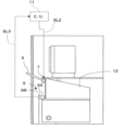
図1において、外設機100は、本発明の実施形態に係る操作機構20を有している。操作機構20は、空間に表示される画像に対して操作を行う非接触ディスプレイ1と、操作者(利用者:操作者或いはユーザー)の手指が接触する接触ディスプレイ21(通常のタッチパネル等)を含んでいる。図示の実施形態では、接触ディスプレイ21に接触することなく、非接触ディスプレイ1のみを操作することにより、給油操作を実行出来る。
明確には図示されていないが、図示の実施形態において、非接触ディスプレイ1を有する操作機構20は、外設機100に設けるのみならず、給油装置44(図7参照)に設けることも出来る。
図示の実施形態は、非接触ディスプレイ1と接触ディスプレイ21の両方を有する操作機構20を備えているが、非接触ディスプレイ1のみを有し、接触ディスプレイ21を含まない操作機構10を構成することも出来る。添付図面においては、非接触ディスプレイ1のみを有する操作機構10は図示されていない。
Hereinafter, an embodiment of the present invention will be described with reference to FIGS.
1, an
Although not clearly shown, in the illustrated embodiment, the
Although the illustrated embodiment includes the
非接触ディスプレイ1は、非接触センサー3と、表示装置2(図3参照:例えば液晶ディスプレイ)、3Dプレート4(図3参照)を含む。非接触ディスプレイ1については、図3を参照して後述する。
図1において、接触ディスプレイ21は、非接触ディスプレイ1に対して垂直方向上方に隣接して配置されている。接触ディスプレイ21には、伝票等を印刷するプリンター22、QRリーダー23、プリペイドカードリーダー24、クレジットカード用のカードリーダー25、RFIDリーダー26、作動ランプ27(3箇所)が設けられている。前記プリンター22、QRリーダー23等の機器は、接触ディスプレイ21で操作する場合と、非接触ディスプレイ1で操作する場合の両方において用いられる(共用される)。
図示はされていないが、非接触ディスプレイ1と接触ディスプレイ21を水平方向に隣接して配置することも出来る。
The
1, the
Although not shown, the
図1において、操作機構20は、操作者の顔を認識するカメラ8、制御装置11(C.U.)を含んでおり、カメラ8と制御装置11は信号ラインSL1により接続される。制御装置11により、カメラ8の映像データから操作者の顔の位置(上下方向位置)を決定し、当該決定された操作者の顔の位置から表示装置2(図3)の水平面に対する傾斜角度、非接触センサー3(図3)の水平面に対する傾斜角度、庇部6(図2)の水平面に対する傾斜角度を決定する。これ等の傾斜角度の決定については、図4~図6を参照して後述する。
In FIG. 1, the
図1の要部側面を示す図2において、非接触ディスプレイ1(表示装置2、非接触センサー3、3Dプレート4:図3参照)全体はカバー12により包囲されており、カバー12における操作機構の操作者側の端面(図2で左側の端面)は開口している。
カバー12の操作者側(図2の左側)の端面の上端部近傍には、斜め上方に延在する庇部6が設けられており、庇部6をカバー12へ取り付けている箇所の近傍には庇部用駆動装置7(例えば電動モータ)が設けられている。庇部用駆動装置7は庇部6の水平面に対する傾斜角度を変動・調節する機能を有している。
庇部用駆動装置7は信号ラインSL2を介して制御装置11と接続されている。
In FIG. 2, which shows a side view of the essential parts of FIG. 1, the entire non-contact display 1 (the display device 2, the
A
The eaves driving device 7 is connected to the
表示装置2(例えば液晶ディスプレイ)と非接触センサー3と3Dプレート4とを含む非接触ディスプレイ1は、太陽の向きと給油装置の設置位置と非接触ディスプレイ1の向き(設置方向)によっては表示装置2と操作者との間に太陽光が照射して、表示装置2と操作者との間の空間に表示される画像が見難くなってしまう恐れがある。
その様な太陽光による外乱を抑制するため、図示の実施形態では、庇部6の水平面に対する傾斜角度を調節(自動制御)している。
給油装置の設置位置と設置方向が決定すれば、太陽光の照射方向、照射角度等は月日、時刻により一定であるため、庇部6により太陽光の照射を遮ることが出来る角度(水平面に対する傾斜角度)は直ちに決定される。また、操作者の顔の位置(上下方向位置)により、庇部6により太陽光の照射を遮ることが出来る角度は相違する。そのため図示の実施形態では、カメラ8(図1)の映像データから操作者の顔の位置を検出し、さらに、月日、時間による太陽光の照射状況に基づいて、制御装置11は、庇部の水平面に対する傾斜角度(庇部6により太陽光の照射を遮ることが出来る角度)を演算する。庇部6の傾斜角度の制御についても、図4~図6を参照して後述する。
In order to suppress such disturbances due to sunlight, in the illustrated embodiment, the inclination angle of the
Once the installation position and installation direction of the fueling device are determined, the angle (tilt angle with respect to the horizontal plane) at which the
図2において、非接触ディスプレイ1を覆うカバー12の操作者側(図2で左側)の端面には、雨水検知手段9が設けられている。雨水検知手段9は雨水受け部9Aと雨水検知センサー9Bを含む。雨水検知手段9の雨水検知センサー9Bと制御装置11は信号ラインSL3により接続されている。
水滴や雪が非接触ディスプレイ1における表示装置2(図3)と操作者との間の空間に入り込んでしまうと、非接触センサー1が水滴や雪の結晶を感知してしまい、操作者の指先の動きと誤認して表示する等の誤動作を惹起する可能性がある。そのような誤動作を防止するため、図示の実施形態では雨水検知手段9を設け、接触ディスプレイ1に雨或いは雪が当たることにより誤動作が発生する可能性が高いと判断した場合に非接触ディスプレイ1の表示を停止し、且つ接触ディスプレイ21による操作のみを受け付ける様に構成している。
雨水検知手段9による制御の詳細は、図6を参照して後述する。
2, a rainwater detection means 9 is provided on the end surface on the operator side (left side in FIG. 2) of the
If water droplets or snow get into the space between the operator and the display device 2 (FIG. 3) in the
The control by the rainwater detection means 9 will be described in detail later with reference to FIG.
図3において、非接触ディスプレイ1は、操作に必要な情報を表示する表示装置2(例えば液晶ディスプレイ)と、操作者(利用者)の指先の動き(指先の位置、移動方向、移動距離等)を非接触で感知する非接触センサー3と、表示装置2と操作者との間の空間に画像を表示する機能を有する3Dプレート4を含んでいる。符号14は表示装置2の支持部材である。
図3で示す非接触ディスプレイ1においては、上下の視野角が狭く、表示装置2と操作者との間の空間に表示される画像が見易い範囲が限定されている。
図示の実施形態では、表示装置2の水平面に対する傾斜角度を調節するための表示装置用駆動装置5(表示装置用モータ)を表示装置2の取り付け部近傍の支持部材14に設けている。そして、カメラ8(図1)の映像データから制御装置11が操作者の顔の位置(上下方向位置)を決定し、決定された操作者の顔の位置から表示装置2の水平面に対する最適な傾斜角度を演算し、当該傾斜角度に対応して表示装置用モータ5を正転或いは逆転する制御信号が制御装置11から発信される。これにより、表示装置2の水平面に対する傾斜角度を、表示装置2と操作者との間の空間に表示される画像が見易くなる様に調節している。
表示装置用モータ5は信号ラインSL4を介して制御装置11と接続されている。
3, the
In the
In the illustrated embodiment, a display device driver 5 (display device motor) for adjusting the tilt angle of the display device 2 relative to the horizontal plane is provided on a
The display motor 5 is connected to the
図示の実施形態では、表示装置2の水平面に対する傾斜角度を調節することに加えて、非接触センサー3の水平面に対する傾斜角度を調節出来る様に構成されている。
図3において、非接触センサー用駆動装置13(非接触センサー用モータ)を非接触センサー3の取り付け部近傍に設け、カメラ8(図1)の映像データから制御装置11が操作者の顔の位置(上下方向位置)を決定し、決定された操作者の顔の位置から非接触センサー3の水平面に対する最適な傾斜角度(非接触ディスプレイ1による操作に最適な傾斜角度)を決定する。そして、当該決定された傾斜角度に対応して非接触センサー用モータ13を正転或いは逆転する制御信号が制御装置11から発信されて、非接触センサー3の水平面に対する傾斜角度を最適な角度に調節している。
非接触センサー3の水平面に対する傾斜角度及び表示装置2の水平面に対する傾斜角度は相関しており、両者は関連して制御される。非接触センサー3の水平面に対する傾斜角度及び表示装置2の水平面に対する傾斜角度の相関関係は、例えば制御装置11に記憶されている。
非接触センサー用モータ13と制御装置11は信号ラインSL5により接続されている。
In the illustrated embodiment, in addition to adjusting the inclination angle of the display device 2 with respect to the horizontal plane, the inclination angle of the
3, a non-contact sensor driver 13 (non-contact sensor motor) is provided near the attachment portion of the
The inclination angle of the
The
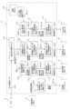
制御装置11の機能ブロック図である図4には、図示の実施形態の非接触ディスプレイ1を構成する表示装置2、非接触センサー3の各々における水平面に対する傾斜角度を調節し、庇部6の水平面に対する傾斜角度を調節し、さらに雨水検知手段9の水滴検知結果に基づき非接触ディスプレイ1の表示を停止する機能を発揮するための構成が示されている。
図4において、制御装置11は、顔の高さ演算ブロック11Aを有している。そして、表示装置2の水平面に対する傾斜角度を調節する制御に関して、表示装置角度演算ブロック11B、表示装置用モータ回転角度決定ブロック11C、表示装置用モータ制御信号発生ブロック11Dを有している。
また制御装置11は、非接触センサー3の水平面に対する傾斜角度を調節する制御に関して、非接触センサー角度演算ブロック11E、非接触センサー用モータ回転角度決定ブロック11F、非接触センサー用モータ制御信号発生ブロック11Gを有している。
さらに制御装置11は、庇部6の水平面に対する傾斜角度を調節する制御に関して、庇部角度演算ブロック11H、庇部用モータ回転角度決定ブロック11I、庇部用モータ制御信号発生ブロック11J、記憶ブロック11Kを有している。
加えて制御装置11は、非接触ディスプレイ停止判断ブロック11Lを有している。
Figure 4, which is a functional block diagram of the
4, the
The
Furthermore, the
In addition, the
顔の高さ演算ブロック11Aは、カメラ8から操作者の顔の映像データを、信号ラインSL1を介して取得し、操作者の顔の位置(上下方向の高さ位置)を演算し、決定する機能を有している。
顔の高さ演算ブロック11Aで演算、決定された「操作者の顔の高さ」は、信号ラインSL6を介して表示装置角度演算ブロック11Bに送信され、信号ラインSL7を介して非接触センサー角度演算ブロック11Eに送信され、信号ラインSL8を介して庇部角度演算ブロック11Hに送信される。
The face
The "height of the operator's face" calculated and determined in the face
表示装置角度演算ブロック11Bは、顔の高さ演算ブロック11Aから取得した「操作者の顔の高さ」に基づき「表示装置2の水平面に対する傾斜角度」を演算し、決定する機能を有している。上述した様に、非接触ディスプレイ1は上下の視野角が狭く、表示装置2と操作者との間の空間に表示される画像が見易い範囲が限定されており、当該見易い範囲は「操作者の顔の高さ」により変動する。そして非接触ディスプレイ1における見易い範囲と「操作者の顔の高さ」と「表示装置2の水平面に対する傾斜角度」には相関関係が存在し、当該相関関係が予め表示装置角度演算ブロック11Bに記録されており、係る相関関係に基づいて、「操作者の顔の高さ」に対して、非接触ディスプレイ1が見易くなる「表示装置2の水平面に対する傾斜角度」が決定される。
明確には図示されていないが、前記相関関係を記憶ブロック11Kに記憶して、表示装置角度演算ブロック11Bからの要求信号により記憶ブロック11Kから前記相関関係が表示装置角度演算ブロック11Bに送信されても良い。
表示装置角度演算ブロック11Bで演算、決定した「表示装置2の水平面に対する傾斜角度」は、信号ラインSL9を介して表示装置用モータ回転角度決定ブロック11Cに送信される。また、図示はされていないが、非接触センサー角度演算ブロック11Eにも送信される。
表示装置用モータ回転角度決定ブロック11Cは、表示装置角度演算ブロック11Bから取得した「表示装置2の水平面に対する傾斜角度」に基づき「当該傾斜角度に調節するために必要な表示装置用モータ5の回転角度(正転或いは逆転)」を演算し、決定する機能を有している。
The display device
Although not clearly shown, the correlation may be stored in
The "tilt angle of the display device 2 with respect to the horizontal plane" calculated and determined by the display device
The display device motor rotation
表示装置用モータ回転角度決定ブロック11Cで演算、決定した「傾斜角度に調節するために必要な表示装置用モータ5の回転角度(正転或いは逆転)」は、信号ラインSL10を介して表示装置用モータ制御信号発生ブロック11Dに送信される。
表示装置用モータ制御信号発生ブロック11Dは、表示装置用モータ回転角度決定ブロック11Cから取得した「傾斜角度に調節するために必要な表示装置用モータ5の回転角度(正転或いは逆転)」に基づき、表示装置用モータ5に対する制御信号を発生させる機能を有している。
表示装置用モータ制御信号発生ブロック11Dからの制御信号は、信号ラインSL4を介して表示装置用モータ5に送信される。
The "rotation angle (forward or reverse) of the display motor 5 required to adjust to the inclination angle" calculated and determined in the display motor rotation
The display motor control
The control signal from the display motor control
非接触センサー角度演算ブロック11Eは、顔の高さ演算ブロック11Aから取得した「操作者の顔の高さ」に基づき「非接触センサー3の水平面に対する傾斜角度」を演算し、決定する機能を有している。非接触センサー3における操作のし易さ、非接触ディスプレイ1による操作に最適な傾斜角度(水平面に対する傾斜角度)、「操作者の顔の高さ」も相関関係があり、係る相関関係に基づいて、「操作者の顔の高さ」に対して、非接触センサー3における操作がし易くなる角度(非接触センサー3の水平面に対する傾斜角度)が決定される。また、上述した様に、「表示装置2の水平面に対する傾斜角度」と「非接触センサー3の水平面に対する傾斜角度」にも相関関係があるので、表示装置角度演算ブロック11Bで決定された「表示装置2の水平面に対する傾斜角度」も非接触センサー角度演算ブロック11Eに送信されて、「非接触センサー3の水平面に対する傾斜角度」を決定するパラメータとして用いられる。前記相関関係については、非接触センサー角度演算ブロック11Eに記憶されていても良いし、記憶ブロック11Kから送信することも出来る。
非接触センサー角度演算ブロック11Eで演算、決定した「非接触センサー3の水平面に対する傾斜角度」は、信号ラインSL11を介して非接触センサー用モータ回転角度決定ブロック11Fに送信される。
非接触センサー用モータ回転角度決定ブロック11Fは、非接触センサー角度演算ブロック11Eから取得した「非接触センサー3の水平面に対する傾斜角度」に基づき「当該傾斜角度に調節するために必要な非接触センサー用モータ13の回転量(回転する角度:正転或いは逆転)」を演算し、決定する機能を有している。
The non-contact sensor
The "inclination angle of the
The non-contact sensor motor rotation
非接触センサー用モータ回転角度決定ブロック11Fで演算、決定した「傾斜角度に調節するために必要な非接触センサー用モータ13の回転角度(正転或いは逆転)」は、信号ラインSL12を介して非接触センサー用モータ制御信号発生ブロック11Gに送信される。
非接触センサー用モータ制御信号発生ブロック11Gは、非接触センサー用モータ回転角度決定ブロック11Fから取得した「傾斜角度に調節するために必要な非接触センサー用モータ13の回転角度(正転或いは逆転)」に基づき、非接触センサー用モータ13に対する制御信号を発生させる機能を有している。
非接触センサー用モータ制御信号発生ブロック11Gからの制御信号は、信号ラインSL5を介して非接触センサー用モータ13に送信される。
The "rotation angle (forward or reverse) of the
The non-contact sensor motor control
The control signal from the non-contact sensor motor control
図4において、記憶ブロック11Kは、庇部6の水平面に対する傾斜角度を調節する際に必要なデータとして、日付、時刻毎の非接触ディスプレイ1に対する太陽光の照射に関するデータを、当該給油装置の設置態様(操作機構20の設置場所、操作機構20の向き等)毎に記憶する機能を有している。
庇部角度演算ブロック11Hは、記憶ブロック11Kから、非接触ディスプレイ1に対する太陽光の照射に関するデータを、信号ラインSL14を介して取得して、非接触ディスプレイ1を照射する太陽光を庇部6が遮断するために「庇部6の水平面に対する傾斜角度」を演算(調整)する機能を有している。すなわち、設置態様、日付(季節)、時刻により、非接触ディスプレイ1に対する太陽光の照射量、照射方向は相違するので、記憶ブロック11Kに記録された非接触ディスプレイ1に対する太陽光の照射に関するデータに基づいて、非接触ディスプレイ1を照射する太陽光を庇部6が遮断する様に、庇部6が延在する角度である「庇部6の水平面に対する傾斜角度」を決定する。以て、操作者の顔の位置から表示装置2と操作者の間に表示される画像の視認が阻害されることを庇部6により防止するためである。
それと共に、庇部角度演算ブロック11Hは、顔の高さ演算ブロック11Aから取得した「操作者の顔の高さ」に基づき「庇部6の水平面に対する傾斜角度」を演算し、当該演算結果により、設置態様、太陽光の照射に関するデータに基づき調節した「庇部6の水平面に対する傾斜角度」を更に調節する。太陽光の照射により、非接触ディスプレイ1における表示装置2と操作者との間の空間に表示される画像の視認が阻害されるか否かは、操作者の顔の位置により状況が異なるからである。そのため、庇部6により表示装置2と操作者の間の空間の視認が遮られていないか否かを判断する必要がある。
庇部角度演算ブロック11Hで演算、決定した「庇部6の水平面に対する傾斜角度」は、信号ラインSL13を介して庇部用モータ回転角度決定ブロック11Iに送信される。
In Figure 4, the
The eaves
At the same time, the eaves
The "inclination angle of the
庇部用モータ回転角度決定ブロック11Iは、庇部角度演算ブロック11Hから取得した「庇部6の水平面に対する傾斜角度」に基づき「当該傾斜角度に調節するために必要な庇部用モータ7の回転角度(正転或いは逆転)」を演算し、決定する機能を有している。
庇部用モータ回転角度決定ブロック11Iで演算、決定した「傾斜角度に調節するために必要な庇部用モータ7の回転角度(正転或いは逆転)」は、信号ラインSL15を介して庇部用モータ制御信号発生ブロック11Jに送信される。
庇部用モータ制御信号発生ブロック11Jは、庇部用モータ回転角度決定ブロック11Iから取得した「傾斜角度に調節するために必要な庇部用モータ7の回転角度(正転或いは逆転)」に基づき、庇部用モータ7に対する制御信号を発生させる機能を有している。
庇部用モータ制御信号発生ブロック11Jからの制御信号は、信号ラインSL2を介して庇部用モータ7に送信される。
The eaves motor rotation
The "rotation angle (forward or reverse) of the eaves motor 7 required to adjust to the inclination angle" calculated and determined in the eaves motor rotation
The eaves motor control
The control signal from the eaves motor control
図4において、非接触ディスプレイ停止判断ブロック11Lは、信号ラインSL3を介して、雨水検知手段9の雨水検知センサー9B(図2)からの水滴検知結果を取得する。そして、雨水検知センサー9Bからの水滴検知の結果から、雨粒や雪の結晶により非接触ディスプレイ1が誤作動を起こす可能性があると判断した場合に非接触ディスプレイ1の表示停止を判断し、非接触ディスプレイ1に対する制御信号を発生させる機能を有している。そして、係る場合に、接触ディスプレイ21による操作のみを受け付ける様にせしめる機能をも有している。
非接触ディスプレイ停止判断ブロック11Lからの制御信号は、信号ラインSL16を介して非接触ディスプレイ1に送信される。
4, the non-contact display stop judgment block 11L acquires the water droplet detection result from the
The control signal from the non-contact display stop judgment block 11L is transmitted to the
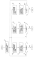
主として図5を参照して、表示装置2、非接触センサー3の各々における水平面に対する傾斜角度と、庇部6の水平面に対する傾斜角度を調節する制御について説明する。
ステップS1では、カメラ8の画像により「操作者の顔の高さ位置」を演算する。当該演算は、制御装置11の顔の高さ演算ブロック11Aにより実行される。
図5のステップS2~S4は表示装置2の水平面に対する傾斜角度の制御における工程であり、ステップS5~ステップS7は非接触センサー3の水平面に対する傾斜角度の制御における工程であり、ステップS8~ステップS10は庇部6の水平面に対する傾斜角度の制御における工程である。
Mainly with reference to FIG. 5, a description will be given of control for adjusting the inclination angles of the display device 2 and the
In step S1, the "height position of the operator's face" is calculated based on the image captured by the camera 8. This calculation is executed by the face
Steps S2 to S4 in Figure 5 are processes for controlling the inclination angle of the display device 2 with respect to the horizontal plane, steps S5 to S7 are processes for controlling the inclination angle of the
ステップS2では、ステップS1で演算した「操作者の顔の高さ位置」に基づき、「表示装置2の水平面に対する傾斜角度」を演算する。当該演算は、表示装置角度演算ブロック11Bにより実行される。そしてステップS3に進む。
ステップS3では、ステップS2で演算した「表示装置2の水平面に対する傾斜角度」に基づき、表示装置用モータ5を駆動、回転(正転或いは逆転)させ、演算された「表示装置2の水平面に対する傾斜角度」、すなわち、操作者の顔の高さ位置に対応して、表示装置2と操作者との間の空間に表示される画像が鮮明になる「表示装置2の水平面に対する傾斜角度」となる様に、表示装置用モータ5の回転角度を決定し、当該回転角度に相当する回転量だけ表示装置用モータ5を回転させる。当該制御は、表示装置用モータ回転角度決定ブロック11C、表示装置用モータ制御信号発生ブロック11Dにより実行される。そしてステップS4に進む。
In step S2, the "tilt angle of the display device 2 with respect to the horizontal plane" is calculated based on the "height position of the operator's face" calculated in step S1. This calculation is executed by the display device
In step S3, the display motor 5 is driven and rotated (forward or reverse) based on the "tilt angle of the display device 2 with respect to the horizontal plane" calculated in step S2, and the rotation angle of the display motor 5 is determined so as to obtain the calculated "tilt angle of the display device 2 with respect to the horizontal plane", i.e., the "tilt angle of the display device 2 with respect to the horizontal plane" that makes the image displayed in the space between the display device 2 and the operator clear in accordance with the height position of the operator's face, and the display motor 5 is rotated by an amount of rotation corresponding to the rotation angle. This control is executed by the display motor rotation angle determination block 11C and the display motor control
ステップS4では、「操作者の顔の高さ位置」に対応した「表示装置2の水平面に対する傾斜角度」の調節と、「非接触センサー3の水平面に対する傾斜角度」の調節と、「庇部6の水平面に対する傾斜角度」の調節が全て行われたか否かを判断する。表示装置2、非接触センサー3、庇部6における水平面に対する傾斜角度の調節が全て行われることにより、非接触ディスプレイ1において表示装置2と操作者との間の空間に表示される画像を鮮明にするために必要な調節が完了する。
ステップS4による判断の結果、表示装置2、非接触センサー3、庇部6における水平面に対する傾斜角度の調節が全て調節された場合(ステップS4が「Yes」)は制御を終了し、全てが調節されていない場合(ステップS4が「No」)は表示装置2、非接触センサー3、庇部6における水平面に対する傾斜角度の調節が全て調節されるまで制御を続行する。
In step S4, it is determined whether or not the adjustments of the "tilt angle of the display device 2 with respect to the horizontal plane" corresponding to the "height position of the operator's face", the "tilt angle of the
As a result of the judgment in step S4, if the adjustments of the inclination angles of the display device 2,
図5において、ステップS5では、ステップS1で演算した「操作者の顔の高さ位置」に基づき、「非接触センサー3の水平面に対する傾斜角度」を演算する。当該演算は、非接触センサー角度演算ブロック11Eにより実行される。そしてステップS6に進む。
ステップS6では、ステップS5で演算した「非接触センサー3の水平面に対する傾斜角度」に基づき、非接触センサー用モータ13を駆動、回転(正転或いは逆転)させ、演算された「非接触センサー3の水平面に対する傾斜角度」(操作者の顔の高さ位置に対応した傾斜角度)となる様に調節する。
当該制御は、非接触センサー用モータ回転角度決定ブロック11F、非接触センサー用モータ制御信号発生ブロック11Gにより実行される。そしてステップS7に進む。
5, in step S5, the "tilt angle of the
In step S6, based on the "tilt angle of the
This control is executed by the non-contact sensor motor rotation
ステップS7ではステップS4と同様に、「操作者の顔の高さ位置」に対応した「水平面に対する傾斜角度」の調節が表示装置2、非接触センサー3、庇部6について全て行われたか否かを判断する。
ステップS7による判断の結果、全て調節された場合(ステップS7が「Yes」)、制御を終了し、全ては調節されていない場合(ステップS7が「No」)は表示装置2、非接触センサー3、庇部6の傾斜角度が全て調節されるまで制御を続行する。
In step S7, similar to step S4, it is determined whether adjustments to the "tilt angle relative to the horizontal plane" corresponding to the "height position of the operator's face" have been made for the display device 2,
As a result of the judgment in step S7, if all have been adjusted (step S7 is "Yes"), the control is terminated, and if all have not been adjusted (step S7 is "No"), the control is continued until the inclination angles of the display device 2,
図5において、ステップS8では、記憶ブロック11K(図4)から非接触ディスプレイ1に対する太陽光の照射に関するデータを受信し、庇部6が太陽光を遮断して、太陽光の照射により非接触ディスプレイ1において表示装置2と操作者との間の空間に表示される画像が不鮮明になることを防止する様に、「庇部6の水平面に対する傾斜角度」を調節(演算)する。
それと共に、ステップS1で演算した「操作者の顔の高さ位置」から「庇部6の水平面に対する傾斜角度」を演算し、前記太陽光に基づき調節した「庇部6の水平面に対する傾斜角度」において、表示装置2と操作者の間に表示される画像が庇部6により操作者の視認が妨げられていないか否かを判断する(必要に応じて当該傾斜角度を再調節する)。当該演算は、庇部角度演算ブロック11Hにより実行される。そしてステップS9に進む。
In Figure 5, in step S8, data regarding the irradiation of sunlight on the
At the same time, the "angle of inclination of the
ステップS9では、ステップS8で演算した「庇部6の水平面に対する傾斜角度」に基づき、庇部用モータ7を駆動、回転(正転或いは逆転)させ、演算された「庇部6の水平面に対する傾斜角度」(すなわち、操作者の顔の高さ位置に対応した傾斜角度)となる様に調節する。係る制御は、庇部用モータ回転角度決定ブロック11I、庇部用モータ制御信号発生ブロック11Jにより実行される。そしてステップS10に進む。
ステップS10では、ステップS4、S7と同様に、「操作者の顔の高さ位置」に対応した「水平面に対する傾斜角度」の調節が表示装置2、非接触センサー3、庇部6の全てについて行われたか否かを判断する。
In step S9, the visor motor 7 is driven and rotated (forward or reverse) based on the "inclination angle of the
In step S10, similar to steps S4 and S7, it is determined whether or not adjustment of the "tilt angle relative to the horizontal plane" corresponding to the "height position of the operator's face" has been performed for all of the display device 2,
主として図6を参照して、雨水検知手段9が水滴検知した場合に非接触ディスプレイ1の作動を停止する制御について説明する。
ステップS11では、雨水検知手段9の雨水検知センサー9Bが雨水(降雨や降雪による水滴、雪の結晶、氷粒)を検知したか否かを判断する。当該判断は、制御装置11の非接触ディスプレイ停止判断ブロック11Lにより実行される。
ステップS11による判断の結果、雨水検知センサー9Bが雨水(水滴、或いは氷粒)を検知した場合(ステップS11が「Yes」)はステップS12に進み、雨水検知センサー9Bが雨水(水滴、或いは氷粒)を検知しない場合(ステップS11が「No」)はステップS14に進む。
Mainly with reference to FIG. 6, the control for stopping the operation of the
In step S11, it is determined whether the
As a result of the determination in step S11, if the
ステップS12(雨水を検知した場合)では、ステップS11で検知した水滴、氷の結晶、氷粒(の量、径)が操作者の指先の動きと誤認される可能性があるか否か、すなわち誤作動が生じる可能性があるか否かを判断する。当該判断は、制御装置11の記憶ブロック11K(図4)に保存される水滴、氷の結晶、氷粒の大きさ(量、径)とそれにより操作者の指先の動きと誤認される可能性(誤作動の可能性)に関するデータを参照して、非接触ディスプレイ停止判断ブロック11Lが実行する。
ステップS12による判断の結果、雨水検知センサー9Bが検知した水滴、雪の結晶、氷粒が操作者の指先の動きと誤認される可能性がある(誤作動の可能性のある)場合(ステップS12が「Yes」)はステップS13に進み、雨水検知センサー9Bが検知した水滴、雪の結晶、氷粒が操作者の指先の動きと誤認されない(誤作動しない)場合(ステップS12が「No」)はステップS14に進む。
In step S12 (when rainwater is detected), it is determined whether or not the water droplets, ice crystals, and ice particles (quantity, diameter) detected in step S11 may be mistaken for the movement of the operator's fingertip, i.e., whether or not a malfunction may occur. This determination is made by the non-contact display stop determination block 11L, referring to data stored in the
As a result of the judgment in step S12, if there is a possibility that the water droplets, snow crystals, and ice particles detected by the
ステップS13(誤作動の可能性がある場合)では、非接触ディスプレイ1の作動を停止し、接触ディスプレイ21による操作、作動のみを可能にする。
一方、ステップS14(ステップS11或いはS12がNoの場合)では、非接触ディスプレイ1の作動は停止せず、非接触ディスプレイ1による操作が可能な状態を継続する。
In step S13 (when there is a possibility of malfunction), the operation of the
On the other hand, in step S14 (if step S11 or S12 is No), the operation of the
図示はされていないが、図示の実施形態において、非接触ディスプレイ1の操作の際に、「ポインターを押した」感を向上するために、超音波センサーを用いて、ポインターを押す動きをした場合に指先に振動を付加することが出来る。また、指先で立体画像を操作した際に、画面の表示を変更し、音を発生し、或いはポインターの色を変化する等により、操作したという感覚(操作感)を向上することが可能である。
Although not shown in the figures, in the illustrated embodiment, in order to improve the feeling of "pushing the pointer" when operating the
図1~図6に示す実施形態によれば、操作機構20は、空間に表示される画像を操作する非接触ディスプレイ1を有しており、空間に表示された画像を操作するのみで給油に関する操作を行うことが出来る。そのため、操作者はディスプレイ(通常のタッチパネル等)に対して物理的に接触する必要がない。そのため、不特定多数の操作者が接触するディスプレイに触れることに起因する感染症の罹患或いはその拡大を防止することが出来る。
また、操作機構20は、非接触ディスプレイ1に加えて、操作者の手指が接触して操作する接触ディスプレイ21(通常のタッチパネル等)を有しているので、非接触ディスプレイ1では操作感覚に違和感を覚えるユーザーであっても、接触ディスプレイ21を使用することにより給油操作を実行することが出来る。
1 to 6, the
In addition to the
図示の実施形態では、カメラ8の映像データから操作者の顔の高さ位置(上下方向位置)を決定し、決定された操作者の顔の高さ位置から表示装置2の水平面に対する傾斜角度を決定している。そして、当該傾斜角度に対応して表示装置用モータ5を正転或いは逆転する制御信号を発信し、表示装置2の水平面に対する傾斜角度を調節している。
また、図示の実施形態では、表示装置2の水平面に対する傾斜角度を調節することに加えて、非接触センサー3の水平面に対する傾斜角度を調節している。すなわち、カメラ8の映像データから操作者の顔の高さ位置(上下方向位置)を決定し、決定された操作者の顔の高さ位置から非接触センサー3の水平面に対する傾斜角度を決定している。
表示装置2の水平面に対する傾斜角度及び非接触センサー3の水平面に対する傾斜角度をそれぞれ操作者の顔の高さ位置から決定し、調節しているので、操作者が異なる場合でも、常に表示装置2と操作者との間の空間に鮮明な画像を常に表示することが出来る。
In the illustrated embodiment, the height position (vertical position) of the operator's face is determined from the image data of the camera 8, and the tilt angle of the display device 2 with respect to the horizontal plane is determined from the determined height position of the operator's face. Then, a control signal is sent to rotate the display device motor 5 forward or backward in accordance with the determined tilt angle, thereby adjusting the tilt angle of the display device 2 with respect to the horizontal plane.
In the illustrated embodiment, in addition to adjusting the tilt angle of the display device 2 with respect to the horizontal plane, the tilt angle of the
The inclination angle of the display device 2 with respect to the horizontal plane and the inclination angle of the
また図示の実施形態では、3Dプレート4の上方の領域に庇部6と、庇部6の水平面に対する傾斜角度を調節するための庇部用モータ7を備え、日付、時刻毎の非接触ディスプレイ1に対する太陽光の照射データに基づき、庇部6が太陽光を遮断する様に庇部6の水平面に対する傾斜角度を演算(自動調節)している。
それと共に、カメラ8の映像データから操作者の顔の高さ位置(上下方向位置)を決定し、決定された操作者の顔の高さ位置から、庇部6により表示装置2と操作者の間の空間の画像を操作者が視認するのを遮られない様に制御している。
庇部6により太陽光線を遮ることにより、表示装置2と操作者との間の空間に太陽光が照射されることを防止し、且つ、表示される画像が庇部6により見難くなることを防止している。
In addition, in the embodiment shown in the figure, a
At the same time, the height position (vertical position) of the operator's face is determined from the image data of the camera 8, and the
The
さらに図示の実施形態では、雨水検知手段9を設け、接触ディスプレイ1に雨或いは雪が当たって非接触ディスプレイ1が誤作動を起こす可能性があると判断した場合に、非接触ディスプレイ1の表示を停止し、且つ接触ディスプレイ21による操作のみを受け付ける様にしている。これにより、水滴や雪の結晶により、非接触ディスプレイ1が誤作動する事態を防止している。
Furthermore, in the illustrated embodiment, a rainwater detection means 9 is provided, and when it is determined that rain or snow may fall on the
図示の実施形態はあくまでも例示であり、本発明の技術的範囲を限定する趣旨の記述ではないことを付記する。
例えば、図示の実施形態に係る操作機構20を防爆構造にすれば、給油所における「危険エリア」に操作機構20を配置することが可能になる。
It should be noted that the illustrated embodiment is merely an example and is not intended to limit the technical scope of the present invention.
For example, if the
1・・・非接触ディスプレイ
2・・・表示装置(例えば液晶ディスプレイ)
3・・・非接触センサー
4・・・3Dプレート
5・・・・表示装置用モータ(表示装置用駆動装置)
6・・・庇部(庇)
7・・・庇部用モータ(庇部用駆動装置)
8・・・カメラ
9・・・雨水検知手段(雨水検知センサー)
10、20・・・操作機構
11・・・制御装置
21・・・接触ディスプレイ
1: Non-contact display 2: Display device (e.g., liquid crystal display)
3: Non-contact sensor 4: 3D plate 5: Display device motor (display device drive device)
6... Eaves section (eaves)
7... Eaves motor (eaves drive device)
8: Camera 9: Rainwater detection means (rainwater detection sensor)
10, 20: Operation mechanism 11: Control device 21: Touch display
Claims (6)
前記非接触ディスプレイは、操作に必要な情報を表示する表示装置と、操作者の指先との距離の動きを非接触で感知する非接触センサーと、表示装置と操作者との間の空間に画像を表示する機能を有する3Dプレートを含み、
操作者の顔を認識するカメラを備え、
前記3Dプレートの上方の領域に庇部を配置し、当該庇部の水平面に対する傾斜角度を調節するための駆動装置を有しており、
カメラの映像データから操作者の顔の位置を決定する機能と、決定された操作者の顔の位置から前記庇部の水平面に対する傾斜角度を決定する機能と、当該傾斜角度に対応して庇部の傾斜角度を調節する前記駆動装置を正転或いは逆転する制御信号を発信する機能を有する制御装置を有することを特徴とする操作機構。 A non-contact display that operates images displayed in the space is included.
The non-contact display includes a display device that displays information necessary for operation, a non-contact sensor that detects the movement of the distance between the display device and the operator's fingertip in a non-contact manner, and a 3D plate that has a function of displaying an image in a space between the display device and the operator;
Equipped with a camera that recognizes the operator's face,
A driving device is provided for disposing an eave portion in an area above the 3D plate and adjusting an inclination angle of the eave portion with respect to a horizontal plane,
An operating mechanism characterized by having a control device having a function of determining the position of the operator's face from camera image data, a function of determining the inclination angle of the eaves portion relative to the horizontal plane from the determined position of the operator's face, and a function of transmitting a control signal to rotate forward or reverse the drive device that adjusts the inclination angle of the eaves portion in accordance with the determined inclination angle.
空間に表示される画像を操作する非接触ディスプレイを含み、
前記非接触ディスプレイは、操作に必要な情報を表示する表示装置と、操作者の指先との距離の動きを非接触で感知する非接触センサーと、表示装置と操作者との間の空間に画像を表示する機能を有する3Dプレートを含み、
雨水検知手段を設け、
前記雨水検知手段により検知された雨或いは雪による誤作動の恐れがあると判断した際に非接触ディスプレイの表示を停止し且つ接触ディスプレイによる操作のみを受け付ける機能を有する制御装置を設けたことを特徴とする操作機構。 A touch display that is touched by an operator's finger,
A non-contact display that operates images displayed in the space is included.
The non-contact display includes a display device that displays information necessary for operation, a non-contact sensor that detects the movement of the distance between the display device and the operator's fingertip in a non-contact manner, and a 3D plate that has a function of displaying an image in a space between the display device and the operator;
A rainwater detection means is provided,
An operating mechanism characterized by being provided with a control device having a function of stopping the display of the non-contact display and accepting only operations via the contact display when it is determined that there is a risk of malfunction due to rain or snow detected by the rainwater detection means .
カメラの映像データから操作者の顔の位置を決定する機能と、決定された操作者の顔の位置から表示装置の水平面に対する傾斜角度を決定する機能と、当該傾斜角度に対応して表示装置の傾斜角度を調節する前記駆動装置を正転或いは逆転する制御信号を発信する機能を有する制御装置を有する請求項2~5の何れか1項の操作機構。
Equipped with a camera that recognizes the operator's face,
The operating mechanism according to any one of claims 2 to 5, further comprising a control device having a function of determining the position of the operator's face from the image data of the camera, a function of determining the inclination angle of the display device relative to the horizontal plane from the determined position of the operator's face, and a function of transmitting a control signal for rotating forward or reverse the drive device that adjusts the inclination angle of the display device in accordance with the determined inclination angle .
Priority Applications (1)
| Application Number | Priority Date | Filing Date | Title |
|---|---|---|---|
| JP2020206441A JP7561597B2 (en) | 2020-12-14 | 2020-12-14 | Operation mechanism |
Applications Claiming Priority (1)
| Application Number | Priority Date | Filing Date | Title |
|---|---|---|---|
| JP2020206441A JP7561597B2 (en) | 2020-12-14 | 2020-12-14 | Operation mechanism |
Publications (2)
| Publication Number | Publication Date |
|---|---|
| JP2022093789A JP2022093789A (en) | 2022-06-24 |
| JP7561597B2 true JP7561597B2 (en) | 2024-10-04 |
Family
ID=82081426
Family Applications (1)
| Application Number | Title | Priority Date | Filing Date |
|---|---|---|---|
| JP2020206441A Active JP7561597B2 (en) | 2020-12-14 | 2020-12-14 | Operation mechanism |
Country Status (1)
| Country | Link |
|---|---|
| JP (1) | JP7561597B2 (en) |
Families Citing this family (1)
| Publication number | Priority date | Publication date | Assignee | Title |
|---|---|---|---|---|
| CN118942139B (en) * | 2024-08-20 | 2025-04-15 | 苏州数界科技有限公司 | A contactless electronic device control system and method based on image recognition |
Citations (5)
| Publication number | Priority date | Publication date | Assignee | Title |
|---|---|---|---|---|
| JP2014229214A (en) | 2013-05-24 | 2014-12-08 | 富士通株式会社 | Touch panel device, control method of touch panel device and program |
| JP2015181065A (en) | 2015-07-13 | 2015-10-15 | キヤノン株式会社 | Image processing apparatus, control method therefor, and program |
| WO2017141956A1 (en) | 2016-02-19 | 2017-08-24 | パナソニックIpマネジメント株式会社 | Space display apparatus |
| US20180011605A1 (en) | 2015-01-15 | 2018-01-11 | Asukanet Company, Ltd. | Apparatus and method for contactless input |
| JP2020056806A (en) | 2017-02-10 | 2020-04-09 | パナソニックIpマネジメント株式会社 | Control device |
Family Cites Families (3)
| Publication number | Priority date | Publication date | Assignee | Title |
|---|---|---|---|---|
| JP3019186B2 (en) * | 1994-09-16 | 2000-03-13 | 株式会社タツノ・メカトロニクス | Mounting structure for outdoor light eaves for outdoor terminal equipment |
| DE4433629A1 (en) * | 1994-09-21 | 1996-03-28 | Gutjahr Joerg | Angle-selective shading device |
| JPH08272328A (en) * | 1995-03-31 | 1996-10-18 | Asahi Glass Co Ltd | Outdoor light emitting display |
-
2020
- 2020-12-14 JP JP2020206441A patent/JP7561597B2/en active Active
Patent Citations (5)
| Publication number | Priority date | Publication date | Assignee | Title |
|---|---|---|---|---|
| JP2014229214A (en) | 2013-05-24 | 2014-12-08 | 富士通株式会社 | Touch panel device, control method of touch panel device and program |
| US20180011605A1 (en) | 2015-01-15 | 2018-01-11 | Asukanet Company, Ltd. | Apparatus and method for contactless input |
| JP2015181065A (en) | 2015-07-13 | 2015-10-15 | キヤノン株式会社 | Image processing apparatus, control method therefor, and program |
| WO2017141956A1 (en) | 2016-02-19 | 2017-08-24 | パナソニックIpマネジメント株式会社 | Space display apparatus |
| JP2020056806A (en) | 2017-02-10 | 2020-04-09 | パナソニックIpマネジメント株式会社 | Control device |
Also Published As
| Publication number | Publication date |
|---|---|
| JP2022093789A (en) | 2022-06-24 |
Similar Documents
| Publication | Publication Date | Title |
|---|---|---|
| EP2024198B1 (en) | Vehicle display apparatus | |
| US11124118B2 (en) | Vehicular display system with user input display | |
| US6282553B1 (en) | Gaze-based secure keypad entry system | |
| US9008904B2 (en) | Graphical vehicle command system for autonomous vehicles on full windshield head-up display | |
| US9656690B2 (en) | System and method for using gestures in autonomous parking | |
| US8284053B2 (en) | Fuel dispenser | |
| CN101593079B (en) | Character input apparatus and character input method | |
| US9446712B2 (en) | Motor vehicle comprising an electronic rear-view mirror | |
| JP7659716B2 (en) | Apparatus for transferring power to or from an electric vehicle and method of controlling same - Patents.com | |
| US20070262965A1 (en) | Input Device | |
| CN101893934A (en) | Method and device for intelligently adjusting screen display | |
| CN105584368A (en) | System For Information Transmission In A Motor Vehicle | |
| RU2617621C2 (en) | Method and device for display hand in hand operator controls the vehicle | |
| JP7561597B2 (en) | Operation mechanism | |
| CN103728727A (en) | Information display system and display method for automatically adjusting visual range | |
| US12202122B2 (en) | Autonomous drive through system and a method thereof | |
| JPH11353118A (en) | Information input device | |
| GB2602765A (en) | Apparatus for transferring electrical power to or from an electric vehicle, and control method thereof | |
| JP2009237746A (en) | Operation device for vehicle | |
| GB2593850A (en) | Apparatus for transferring electrical power to or from an electric vehicle, and control method thereof | |
| JP2000247398A (en) | Refueling system | |
| GB2350457A (en) | Self-service terminal | |
| CN120017819A (en) | Interaction method, display device, storage medium and transportation tool | |
| GB2621037A (en) | Apparatus for transferring electrical power to or from an electric vehicle, and control method thereof | |
| JPH05266050A (en) | Terminal device with automatic adjustment function |
Legal Events
| Date | Code | Title | Description |
|---|---|---|---|
| A621 | Written request for application examination |
Free format text: JAPANESE INTERMEDIATE CODE: A621 Effective date: 20231107 |
|
| A977 | Report on retrieval |
Free format text: JAPANESE INTERMEDIATE CODE: A971007 Effective date: 20240531 |
|
| A131 | Notification of reasons for refusal |
Free format text: JAPANESE INTERMEDIATE CODE: A131 Effective date: 20240603 |
|
| A521 | Request for written amendment filed |
Free format text: JAPANESE INTERMEDIATE CODE: A523 Effective date: 20240710 |
|
| TRDD | Decision of grant or rejection written | ||
| A01 | Written decision to grant a patent or to grant a registration (utility model) |
Free format text: JAPANESE INTERMEDIATE CODE: A01 Effective date: 20240917 |
|
| A61 | First payment of annual fees (during grant procedure) |
Free format text: JAPANESE INTERMEDIATE CODE: A61 Effective date: 20240924 |
|
| R150 | Certificate of patent or registration of utility model |
Ref document number: 7561597 Country of ref document: JP Free format text: JAPANESE INTERMEDIATE CODE: R150 |