JP7563237B2 - Weights - Google Patents
Weights Download PDFInfo
- Publication number
- JP7563237B2 JP7563237B2 JP2021031158A JP2021031158A JP7563237B2 JP 7563237 B2 JP7563237 B2 JP 7563237B2 JP 2021031158 A JP2021031158 A JP 2021031158A JP 2021031158 A JP2021031158 A JP 2021031158A JP 7563237 B2 JP7563237 B2 JP 7563237B2
- Authority
- JP
- Japan
- Prior art keywords
- main body
- weight
- slit
- central axis
- rope
- Prior art date
- Legal status (The legal status is an assumption and is not a legal conclusion. Google has not performed a legal analysis and makes no representation as to the accuracy of the status listed.)
- Active
Links
Images

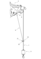


Classifications
-
- B—PERFORMING OPERATIONS; TRANSPORTING
- B66—HOISTING; LIFTING; HAULING
- B66C—CRANES; LOAD-ENGAGING ELEMENTS OR DEVICES FOR CRANES, CAPSTANS, WINCHES, OR TACKLES
- B66C13/00—Other constructional features or details
- B66C13/18—Control systems or devices
- B66C13/50—Applications of limit circuits or of limit-switch arrangements
-
- B—PERFORMING OPERATIONS; TRANSPORTING
- B66—HOISTING; LIFTING; HAULING
- B66C—CRANES; LOAD-ENGAGING ELEMENTS OR DEVICES FOR CRANES, CAPSTANS, WINCHES, OR TACKLES
- B66C23/00—Cranes comprising essentially a beam, boom, or triangular structure acting as a cantilever and mounted for translatory of swinging movements in vertical or horizontal planes or a combination of such movements, e.g. jib-cranes, derricks, tower cranes
- B66C23/88—Safety gear
- B66C23/90—Devices for indicating or limiting lifting moment
Landscapes
- Engineering & Computer Science (AREA)
- Mechanical Engineering (AREA)
- Automation & Control Theory (AREA)
- Load-Engaging Elements For Cranes (AREA)
- Jib Cranes (AREA)
- Portable Nailing Machines And Staplers (AREA)
- Diaphragms For Electromechanical Transducers (AREA)
- Buildings Adapted To Withstand Abnormal External Influences (AREA)
Description
本発明は、重錘に関する。 The present invention relates to a weight.
例えばクレーンのジブから垂下される吊り荷ロープの過巻を検出するために重錘が用いられている。この重錘は、ジブに配置されたリミットスイッチに取り付けられたワイヤロープ等によって吊り下げられている。この重錘は、筒状であり、吊り荷ロープが通過する挿通穴を有する。この重錘は、吊り荷ロープを巻き上げると、この吊り荷ロープに吊り下げられているフックが下方から接触し、このフックと共に上方に持ち上げられる。その結果、リミットスイッチに加わる力が減少し、吊り荷ロープの過巻を検出することができる(特開2013-18616号公報参照)。 For example, a weight is used to detect overspooling of a load rope hanging from the jib of a crane. This weight is suspended by a wire rope or the like attached to a limit switch arranged on the jib. This weight is cylindrical and has an insertion hole through which the load rope passes. When the load rope is wound up, the weight comes into contact with a hook suspended from the load rope from below and is lifted upward together with the hook. As a result, the force applied to the limit switch is reduced, making it possible to detect overspooling of the load rope (see JP 2013-18616 A).
特許文献1に記載の重錘は、ワイヤロープに吊り下げられた状態で、挿通穴の一端側から吊り荷ロープが挿入される。そのため、特許文献1に記載の重錘によると、吊り荷ロープを挿通穴に通過させたうえで、この吊り荷ロープにフックを取り付けることを要する。
The weight described in
従って、特許文献1に記載の重錘によると、吊り荷ロープにフックを取り付ける前に吊り荷ロープを重錘に挿入しておくことを要すると共に、重錘の着脱の都度、吊り荷ロープとフックとを着脱することが必要となり、重錘の着脱作業性が悪い。
Therefore, with the weight described in
そのため、今日では、特許文献2に記載されているように、軸方向に横断するロープ通過許容空間を有する部分筒状の重錘本体と、この重錘本体のロープ通過許容空間を塞ぐように重錘本体に着脱可能に装着される着脱部材とを有する重錘が提案されている。特許文献2に記載の重錘は、ロープ通過許容空間から重錘本体内に吊り荷ロープを挿入したうえで、このロープ通過許容空間を着脱部材で塞ぐことで、重錘本体内に吊り荷ロープを保持することができる。そのため、特許文献2に記載の重錘によると、重錘の着脱に際して吊り荷ロープからフックを着脱することを要しない。
For this reason, as described in
しかしながら、特許文献2に記載の構成によっても、重錘本体と着脱部材との着脱作業が必要となる。そのため、吊り荷ロープとの着脱容易化の観点において、さらなる改良の余地がある。
However, even with the configuration described in
上記不都合に鑑みて、本発明は、吊り荷ロープに対する着脱が容易な重錘を提供することを目的とする。 In view of the above inconveniences, the present invention aims to provide a weight that can be easily attached and detached from a lifting rope.
上記課題を解決するためになされた本発明の一態様に係る重錘は、建設機械の起伏部材から垂下される吊り荷ロープの過巻を検出する重錘であって、上記起伏部材から垂下される紐状部によって吊り下げられ、上記吊り荷ロープを取り囲む筒状の本体を備え、上記本体が、その中心軸の両端に亘って延び、上記吊り荷ロープを挿抜可能なスリットを有し、上記スリットが、上記中心軸に対して傾斜した傾斜部を有する。 The weight according to one aspect of the present invention, which has been made to solve the above problems, is a weight that detects over-winding of a load rope hanging from a hoisting member of a construction machine, and is suspended by a string-like portion hanging from the hoisting member and has a cylindrical main body that surrounds the load rope, the main body extends to both ends of its central axis and has a slit through which the load rope can be inserted and removed, and the slit has an inclined portion that is inclined with respect to the central axis.
本発明の一態様に係る重錘は、吊り荷ロープに対する着脱が容易である。 The weight according to one aspect of the present invention can be easily attached to and detached from the lifting rope.
[本発明の実施形態の説明]
最初に本発明の実施態様を列記して説明する。
[Description of the embodiments of the present invention]
First, the embodiments of the present invention will be listed and described.
上記課題を解決するためになされた本発明の一態様に係る重錘は、建設機械の起伏部材から垂下される吊り荷ロープの過巻を検出する重錘であって、上記起伏部材から垂下される紐状部によって吊り下げられ、上記吊り荷ロープを取り囲む筒状の本体を備え、上記本体が、その中心軸の両端に亘って延び、上記吊り荷ロープを挿抜可能なスリットを有し、上記スリットが、上記中心軸に対して傾斜した傾斜部を有する。 The weight according to one aspect of the present invention, which has been made to solve the above problems, is a weight that detects over-winding of a load rope hanging from a hoisting member of a construction machine, and is suspended by a string-like portion hanging from the hoisting member and has a cylindrical body that surrounds the load rope, the body extends to both ends of its central axis, has a slit through which the load rope can be inserted and removed, and the slit has an inclined portion that is inclined with respect to the central axis.
当該重錘は、上記本体が、その中心軸の両端に亘って延び、上記吊り荷ロープを挿抜可能なスリットを有するので、このスリットを通して上記吊り荷ロープを上記本体の内外に挿抜することができる。当該重錘は、上記スリットが上記本体の中心軸に対して傾斜した傾斜部を有するので、上記紐状部によって吊り下げられ、かつ上記吊り荷ロープが上記本体の内部に挿通している状態で、この吊り荷ロープが上記スリットから抜け難い。そのため、当該重錘は、上記吊り荷ロープに対する着脱が容易であると共に、上記吊り荷ロープの上記本体からの意図しない抜け出しを抑制することができる。 The weight has a body that extends across both ends of its central axis and has a slit through which the load rope can be inserted and removed, so that the load rope can be inserted and removed from the inside and outside of the body through the slit. The weight has an inclined portion in which the slit is inclined with respect to the central axis of the body, so that when the weight is suspended by the string-like portion and the load rope is inserted inside the body, the load rope is unlikely to come out of the slit. Therefore, the weight is easy to attach and detach from the load rope, and can prevent the load rope from coming out of the body unintentionally.
上記中心軸に対する上記傾斜部の平均傾斜角としては30°以上60°以下が好ましい。上記中心軸に対する上記傾斜部の平均傾斜角が上記下限未満であると、上記吊り荷ロープに対する当該重錘の着脱容易性が高められる反面、上記吊り荷ロープが当該重錘から抜け出すおそれがある。一方、上記中心軸に対する上記傾斜部の平均傾斜角が上記上限を超えると、上記吊り荷ロープの抜け出しを防止しやすい反面、上記吊り荷ロープに対する当該重錘の着脱容易性が不十分となるおそれがある。 The average inclination angle of the inclined portion relative to the central axis is preferably 30° or more and 60° or less. If the average inclination angle of the inclined portion relative to the central axis is less than the lower limit, the ease of attaching and detaching the weight to the load rope is increased, but there is a risk that the load rope may come loose from the weight. On the other hand, if the average inclination angle of the inclined portion relative to the central axis exceeds the upper limit, it is easier to prevent the load rope from coming loose, but there is a risk that the ease of attaching and detaching the weight to the load rope may be insufficient.
上記中心軸に対する上記傾斜部の傾斜角が一定であるとよい。このように、上記中心軸に対する上記傾斜部の傾斜角が一定であることによって、上記吊り荷ロープに対する当該重錘の着脱容易性をより高めることができる。 It is preferable that the inclination angle of the inclined portion relative to the central axis is constant. In this way, by having a constant inclination angle of the inclined portion relative to the central axis, it is possible to further increase the ease of attaching and detaching the weight to the suspension rope.
上記スリットが上記傾斜部からなるとよい。このように、上記スリットが上記傾斜部からなることによって、上記本体の周方向における上記スリットの長さを長くして、上記吊り荷ロープの上記本体からの意図しない抜け出しを容易に抑制することができる。 It is preferable that the slit is made of the inclined portion. In this way, by making the slit be made of the inclined portion, the length of the slit in the circumferential direction of the main body can be increased, making it easy to prevent the load rope from unintentionally slipping out of the main body.
上記スリットの幅が、上記本体の径方向外側から内側に向けて漸減するとよい。このように、上記スリットの幅が、上記本体の径方向外側から内側に向けて漸減することによって、上記吊り荷ロープの上記本体からの意図しない抜け出しを抑制しつつ、上記吊り荷ロープの上記本体内への挿入の容易化を図ることができる。 The width of the slit may be gradually decreased from the radially outer side to the radially inner side of the main body. In this way, the width of the slit may be gradually decreased from the radially outer side to the radially inner side of the main body, which makes it easier to insert the load rope into the main body while preventing the load rope from unintentionally slipping out of the main body.
上記本体の周方向における上記スリットの巻き数が1より小さいとよい。このように、上記本体の周方向における上記スリットの巻き数が1より小さいことによって、上記吊り荷ロープに対する当該重錘の着脱容易性をより高めることができる。 The number of turns of the slit in the circumferential direction of the main body is preferably less than 1. In this way, by having the number of turns of the slit in the circumferential direction of the main body be less than 1, the ease of attaching and detaching the weight to and from the lifting rope can be further improved.
上記本体の上記スリットが形成されていない領域の外周面に設けられ、上記紐状部に接続される一対の取付部を備え、上記一対の取付部が、上記本体の中心軸を挟んで対向する位置に配置されているとよい。このように、上記本体の上記スリットが形成されていない領域の外周面に設けられ、上記紐状部に接続される一対の取付部を備え、上記一対の取付部が、上記本体の中心軸を挟んで対向する位置に配置されていることによって、上記吊り荷ロープに対する当該重錘の着脱容易性をより高めることができる。 It is preferable that the outer peripheral surface of the main body in the area where the slit is not formed is provided with a pair of attachment parts connected to the string-like portion, and the pair of attachment parts are arranged in opposing positions across the central axis of the main body. In this way, the outer peripheral surface of the main body in the area where the slit is not formed is provided with a pair of attachment parts connected to the string-like portion, and the pair of attachment parts are arranged in opposing positions across the central axis of the main body, which makes it possible to further increase the ease of attachment and detachment of the weight to the hanging rope.
上記スリットが、一対の上記傾斜部と、上記一対の傾斜部同士の間に配置される上記傾斜部よりも幅広の窓部とを有しており、上記一対の傾斜部の中心線同士が一致していないとよい。このように、上記窓部を介して配置される上記一対の傾斜部の中心線同士が一致していないことによって、上記吊り荷ロープの上記本体からの意図しない抜け出しを容易に抑制しやすい。また、上記一対の傾斜部同士の間に上記窓部が配置されていることで、上記吊り荷ロープを上記本体内に挿入する際に、上記一対の傾斜部に上記吊り荷ロープを通しやすい。 The slit may have a pair of the inclined portions and a window portion that is wider than the inclined portions and is disposed between the pair of inclined portions, and the center lines of the pair of inclined portions may not coincide with each other. In this way, the center lines of the pair of inclined portions disposed through the window portion do not coincide with each other, which makes it easy to prevent the load rope from unintentionally slipping out of the main body. In addition, the window portion is disposed between the pair of inclined portions, which makes it easy to pass the load rope through the pair of inclined portions when inserting the load rope into the main body.
上記一対の傾斜部同士の傾斜方向が逆であるとよい。このように、上記一対の傾斜部同士の傾斜方向が逆であることによって、上記吊り荷ロープの上記本体からの意図しない抜け出しをより確実に抑制することができる。 It is preferable that the inclination directions of the pair of inclined portions are opposite to each other. In this way, by having the inclination directions of the pair of inclined portions be opposite to each other, it is possible to more reliably prevent the suspension rope from unintentionally coming loose from the main body.
上記本体の周方向において、上記一対の傾斜部の上記窓部に接続される側の端部同士の位置が一致していないとよい。このように、上記本体の周方向において、上記一対の傾斜部の上記窓部に接続される側の端部同士の位置が一致していないことによって、上記吊り荷ロープの上記本体からの意図しない抜け出しをより確実に抑制することができる。 In the circumferential direction of the main body, it is preferable that the positions of the ends of the pair of inclined portions that are connected to the window portions do not match. In this way, by having the positions of the ends of the pair of inclined portions that are connected to the window portions not match in the circumferential direction of the main body, it is possible to more reliably prevent the suspension rope from unintentionally coming loose from the main body.
上記窓部が、上記本体の周方向に延び、かつ上記本体の中心軸方向に対向する第1端縁及び第2端縁を有しており、一方の上記傾斜部が、上記第1端縁の周方向の一方側に接続されており、他方の上記傾斜部が、上記第2端縁の周方向の他方側に接続されているとよい。このように、上記窓部が、上記本体の周方向に延び、かつ上記本体の中心軸方向に対向する第1端縁及び第2端縁を有しており、一方の上記傾斜部が、上記第1端縁の周方向の一方側に接続されており、他方の上記傾斜部が、上記第2端縁の周方向の他方側に接続されていることによって、上記吊り荷ロープの上記本体からの意図しない抜け出しをより確実に抑制することができる。 The window portion may have a first edge and a second edge that extend in the circumferential direction of the main body and face each other in the central axis direction of the main body, one of the inclined portions being connected to one side of the first edge in the circumferential direction, and the other of the inclined portions being connected to the other side of the second edge in the circumferential direction. In this way, the window portion may have a first edge and a second edge that extend in the circumferential direction of the main body and face each other in the central axis direction of the main body, one of the inclined portions being connected to one side of the first edge in the circumferential direction, and the other of the inclined portions being connected to the other side of the second edge in the circumferential direction, thereby more reliably preventing the suspension rope from unintentionally coming loose from the main body.
上記本体の径方向視において、上記窓部が矩形状であるとよい。このように、上記本体の径方向視において、上記窓部が矩形状であることによって、上記本体の周方向において、上記一対の傾斜部の上記窓部に接続される側の端部同士の位置を離しやすい。その結果、上記吊り荷ロープの上記本体からの意図しない抜け出しをより確実に抑制しやすい。 The window portion may be rectangular when viewed in the radial direction of the main body. In this way, when viewed in the radial direction of the main body, the window portion may be rectangular, which makes it easier to separate the ends of the pair of inclined portions connected to the window portion in the circumferential direction of the main body. As a result, it is easier to more reliably prevent the lifting rope from unintentionally coming loose from the main body.
なお、本発明において、「本体の中心軸に対する傾斜部の平均傾斜角」とは、傾斜部の任意の3点における本体の中心軸に対する傾斜角の平均値をいう。傾斜角が「一定」とは、傾斜角の差の最大値が±10°以内であることをいい、好ましくは±5°以内、より好ましくは±1°以内であることをいう。スリットの幅が「漸減する」とは、スリットの幅が連続的及び段階的に減少する態様を含む。「本体の周方向におけるスリットの巻き数」とは、周方向に1周巻かれた場合を基準とする比率を意味する。「傾斜部の中心線」とは、傾斜部及びこの傾斜部をその形状に沿って延長した仮想領域の長手方向に沿う中心線を意味する。 In the present invention, the "average inclination angle of the inclined portion relative to the central axis of the body" refers to the average value of the inclination angle of any three points of the inclined portion relative to the central axis of the body. The inclination angle being "constant" means that the maximum difference in the inclination angle is within ±10°, preferably within ±5°, and more preferably within ±1°. The width of the slit "decreases gradually" includes a mode in which the width of the slit decreases continuously and stepwise. The "number of turns of the slit in the circumferential direction of the body" refers to a ratio based on the case where the slit is wound once in the circumferential direction. The "center line of the inclined portion" refers to the center line along the longitudinal direction of the inclined portion and the imaginary area obtained by extending this inclined portion along its shape.
[本発明の実施形態の詳細]
以下、適宜図面を参照しつつ、本発明の実施の形態を詳説する。
[Details of the embodiment of the present invention]
Hereinafter, an embodiment of the present invention will be described in detail with reference to the drawings as appropriate.
[第一実施形態]
[建設機械]
図1及び図2に示すように、建設機械1は、下部走行体2と、下部走行体2上に水平回転可能に搭載される上部旋回体3と、上部旋回体3に起伏可能に取り付けられる起伏部材20とを備える。本実施形態において、建設機械1はクレーンである。起伏部材20は、上部旋回体3に起伏可能に取り付けられるブーム4と、ブーム4の先端部に起伏可能に連結されるジブ5と、ジブ5の先端部に設けられるシーブ6とを有する。また、建設機械1は、起伏部材20から垂下される吊り荷ロープ7と、起伏部材20に固定されるリミットスイッチ8と、リミットスイッチ8に接続されて起伏部材20から垂下される紐状部9と、紐状部9によって吊り下げられる重錘10とを備える。図3に示すように、紐状部9は、起伏部材20の左右両側から垂下されている。重錘10は、起伏部材20から垂下される吊り荷ロープ7の過巻を検出可能に構成される。建設機械1は、吊り荷ロープ7に吊り下げられるフック11をさらに備える。なお、本明細書において、「前」、「後」、「左右」とは、吊り荷ロープが垂下される起伏部材(例えばジブ又はブーム)の先端側を前側、基端側を後側とした場合の「前」、「後」及び「左右」を意味する。
[First embodiment]
[Construction machinery]
As shown in Figures 1 and 2, the
<重錘>
図2及び図3に示すように、当該重錘10は、吊り荷ロープ7を取り囲む筒状の本体21を備える。また、当該重錘10は、本体21の外周面に設けられ、紐状部9に接続される一対の取付部22を備える。当該重錘10は、本体21及び一対の取付部22からなる。
<Weight>
2 and 3 , the
図4~図10に示すように、本体21は筒状であり、好ましくは円筒状である。本体21の内径及び外径は、その中心軸方向に亘って均一であることが好ましい。本体21は、その中心軸Pの両端に亘って延び、吊り荷ロープ7を挿抜可能なスリット21aを有する。換言すると、本体21には、その中心軸Pの方向に横断するスリット21aが設けられている。スリット21aは、本体21の中心軸Pに対して傾斜した傾斜部を有する。本実施形態において、スリット21aは上記傾斜部からなる。当該重錘10は、スリット21aが上記傾斜部からなることによって、本体21の周方向におけるスリット21aの長さを長くして、吊り荷ロープ7の本体21からの意図しない抜け出しを容易に抑制することができる。本体21の中心軸方向視におけるスリット21aの両端間の間隔は、吊り荷ロープ7の径よりも大きいことが好ましい。
As shown in Figs. 4 to 10, the
当該重錘10は、紐状部9によって吊り下げられた状態で一対の取付部22が水平に保たれる。また、当該重錘10は、吊り荷ロープ7が本体21内に挿通された状態で、本体21の中心軸Pが鉛直方向に延びている。そのため、当該重錘10は、中心軸Pに対してスリット21aが傾斜していることで、スリット21aを塞ぐ着脱部材を有していなくても、使用状態において吊り荷ロープ7が本体21外に抜け出し難い。
The
上述のように、スリット21aは、吊り荷ロープ7を挿抜可能に構成されている。そのため、スリット21aの最小幅は吊り荷ロープ7の径以上とされる。本体21の中心軸方向に沿ってスリット21aの幅は均一であることが好ましい。
As described above, the
スリット21aの幅は、本体21の径方向(つまり本体21の厚さ方向)において均一であってもよい。一方、スリット21aの幅は、本体21の径方向外側から内側に向けて漸減していてもよい。当該重錘10は、スリット21aの幅が本体21の径方向外側から内側に向けて漸減することで、吊り荷ロープ7の本体21からの意図しない抜け出しを抑制しつつ、吊り荷ロープ7の本体21内への挿入の容易化を図ることができる。
The width of the
スリット21aの傾斜方向(すなわち、上記傾斜部の傾斜方向)は、スリット21aの両端に亘って同じである。スリット21aは、例えば本体21の中心軸Pを中心として螺旋状又は部分螺旋状に延びている。このように、スリット21aが螺旋状又は部分螺旋状であることによって、吊り荷ロープ7の本体21からの意図しない抜け出しを抑制しやすい。なお、スリット21aは、本体21の正面視(径方向視)において本体21を直線状に横断する形状とすることも可能である。
The inclination direction of the
本体21の中心軸Pに対する上記傾斜部の平均傾斜角の下限としては、30°が好ましく、40°がより好ましい。一方、上記平均傾斜角の上限としては、60°が好ましく、50°がより好ましい。さらに上記平均傾斜角としては45°が最も好ましい。上記平均傾斜角が上記下限に満たないと、吊り荷ロープ7に対する本体21の着脱容易性が高められる反面、吊り荷ロープ7が本体21から意図せず抜け出るおそれがある。逆に、上記平均傾斜角が上記上限を超えると、吊り荷ロープ7の抜け出しを防止しやすい反面、吊り荷ロープ7に対する本体21の着脱容易性が低下するおそれがある。
The lower limit of the average inclination angle of the inclined portion relative to the central axis P of the
中心軸Pに対する上記傾斜部の傾斜角は一定であることが好ましい。すなわち、本実施形態においては、上記傾斜部の傾斜角は、本体21の中心軸方向の両端に亘って同じであることが好ましい。この構成によると、当該重錘10は、吊り荷ロープ7に対する本体21の着脱容易性をより高めることができる。
The inclination angle of the inclined portion with respect to the central axis P is preferably constant. That is, in this embodiment, the inclination angle of the inclined portion is preferably the same on both ends of the central axis of the
本体21の周方向におけるスリット21aの巻き数は1より小さいことが好ましい。この構成によると、当該重錘10は、吊り荷ロープ7に対する本体21の着脱容易性をより高めることができる。
It is preferable that the number of turns of the
取付部22は、本体21の外周面から本体21の径方向外側に突出している。取付部22は、紐状部9と接続される係止孔22aを有する。なお、取付部22の具体的形状は、特に限定されるものではなく、例えば本体21の外周面から本体21の径方向外側に突出する突出部と、この突出部に接続されるシャックル等からなる係止部とを有し、この係止部によって紐状部9と接続可能に構成されていてもよい。
The mounting
一対の取付部22は、本体21の重心を挟んで対向する位置に配置されていることが好ましい。本実施形態では、一対の取付部22は、本体21の中心軸Pを挟んで対向する位置に配置されている。一対の取付部22は、本体21のスリット21aが形成されていない領域の外周面に設けられている。換言すると、スリット21aは、本体21の中心軸Pと一対の取付部22とを通る仮想平面を基準として一方側に突出する領域内に形成されている。この構成によると、当該重錘10は、吊り荷ロープ7の着脱時に取付部22が吊り荷ロープ7と干渉するのを防止でき、吊り荷ロープ7に対する本体21の着脱容易性をより高めることができる。また、図2に示すように、本体21は、紐状部9によって吊り下げられた状態で、本体21の中心軸Pと一対の取付部22とを通る仮想平面を基準として一方(図2においては前方)に突出する側の領域が吊り荷ロープ7と選択的に接触しやすい。そのため、当該重錘10は、本体21の吊り荷ロープ7と接触しない側の領域内にスリット21aを設けることで、吊り荷ロープ7の本体21からの意図しない抜け出しを容易に抑制することができる。
The pair of mounting
本体21の周方向における一対の取付部22の中間位置を基準とした場合、スリット21aの両端は、この中間位置を挟んで反対側に位置することが好ましい。この構成によると、当該重錘10は、吊り荷ロープ7が本体21内に挿通された使用状態におけるスリット21aへの吊り荷ロープ7の意図しない挿入を抑制しやすい。
When the midpoint of the pair of mounting
<建設機械のその他の構成>
下部走行体2は、クローラ、ホイール等の走行装置を有する。上部旋回体3は、操縦者用キャビン12、ブーム4を起伏させるブーム起伏ウインチ13、ジブ5を起伏させるジブ起伏ウインチ14、吊り荷ロープ7を巻き上げる巻上げウインチ15等を有する。ブーム4は、例えば上部旋回体3に取り付けられる下部ブームと、1又は複数の中間ブームと、タワーキャップとを長手方向の基端側から先端側にこの順で有する。また、このブーム4としては、タワーキャップに代えて、上部ブームを用いた構成とすることも可能である。
<Other configurations of construction machinery>
The
ジブ5は、例えば複数のパーシャルジブを長手方向に接続して形成される。ジブ5の基端側のパーシャルジブは、ブーム4の先端部分に連結される。
The
吊り荷ロープ7は、シーブ6から垂下されている。吊り荷ロープ7は、シーブ6に掛け回されて鉛直下方に垂下されている。
The
フック11は、巻上げウインチ15から繰り出された吊り荷ロープ7に吊持されている。
The
リミットスイッチ8は、吊り荷ロープ7の垂下位置と前後方向に間隔を空けて配置されている。これにより、リミットスイッチ8に接続される紐状部9は、吊り荷ロープ7の垂下位置と前後方向に離れた位置から垂下される。そのため、当該建設機械1においては、重錘10の本体21内に吊り荷ロープ7を挿通させた状態で、重錘10に対して紐状部9が垂下される側に戻る力が作用する。その結果、当該重錘10の本体21は、本体21の中心軸Pと一対の取付部22とを通る仮想平面を基準として前方に位置する領域が吊り荷ロープ7と連続的に接触しやすい。従って、当該重錘10は、本体21の吊り荷ロープ7と接触する側と反対側の領域内にスリット21aを設けることで、吊り荷ロープ7の本体21からの意図しない抜け出しを容易に抑制することができる。
The
紐状部9は、吊り荷ロープ7の垂下位置と前後方向に離れた位置で起伏部材(本実施形態ではジブ5)の左右両側から垂下されている。つまり、図3に示すように、当該建設機械1は、ジブ5の左右両側から垂下される一対の紐状部9a、9bを有する。一方の紐状部9aの上端は、リミットスイッチ8に接続されている。他方の紐状部9bの上端は、左右方向においてリミットスイッチ8に対向する位置で、ジブ5に接続されている。紐状部9としては、例えばワイヤロープ、チェーン、リンク等が挙げられる。紐状部9a、9bは、下端部に取付部22と接続するためのリング状の係合部を有していてもよい。
The string-
<利点>
当該重錘10は、本体21が、その中心軸の両端に亘って延び、吊り荷ロープ7を挿抜可能なスリット21aを有するので、このスリット21aを通して吊り荷ロープ7を本体21の内外に挿抜することができる。これにより、当該重錘10は、建設機械1の組立作業のどの時点でも本体21の内部に吊り荷ロープ7を挿入することができる。当該重錘10は、スリット21aが本体21の中心軸Pに対して傾斜した傾斜部を有しているので、紐状部9によって吊り下げられ、かつ吊り荷ロープ7が本体21の内部に挿通している状態で、この吊り荷ロープ7がスリット21aから抜け難い。そのため、当該重錘10は、吊り荷ロープ7に対する着脱が容易であると共に、吊り荷ロープ7の本体21からの意図しない抜け出しを抑制することができる。
<Advantages>
The
当該重錘10は、従来の重錘が備えるような着脱部材を有しないので、この着脱部材の落下のおそれがない。さらに、当該重錘10は、この着脱部材の落下を防止するための機構を設けることを要しない。そのため、当該重錘10は、部品点数を少なくすることができる。これにより、当該重錘10は、着脱部材の落下のトラブルを回避できると共に、全体の構造を簡素化することで製造コストを抑えることができる。さらに、当該重錘10は、上記着脱部材の着脱作業等を省略できるので、吊り荷ロープ7の設置作業の工数を減少することができる。従って、当該重錘10は、吊り荷ロープ7の設置作業時間を短縮することができる。
Since the
[第二実施形態]
<重錘>
図26及び図27の重錘90は、建設機械の起伏部材から垂下される吊り荷ロープの過巻を検出する。当該重錘90は、図4~図10の重錘10に代えて用いることができる。当該重錘90は、上記起伏部材から垂下される紐状部によって吊り下げられ、上記吊り荷ロープを取り囲む筒状の本体91を備える。本体91は、その中心軸Pの両端に亘って延び、上記吊り荷ロープを挿抜可能なスリット92を有する。スリット92は、一対の傾斜部(第1傾斜部92a及び第2傾斜部92b)と、第1傾斜部92aと第2傾斜部92bとの間に配置される窓部92cとを有する。より詳しくは、スリット92は、一対の傾斜部92a、92b及び窓部92cからなる。窓部92cは、第1傾斜部92a及び第2傾斜部92bよりも幅広である。なお、当該重錘90は、本体91のスリット92が形成されていない領域の外周面に、上記紐状部に接続される一対の取付部を有していてもよい。当該重錘90が一対の取付部を有する場合、これらの取付部は、本体91の中心軸Pを挟んで対向する位置に配置されていることが好ましい。
[Second embodiment]
<Weight>
The
本体91は、好ましくは円筒状である。本体91の内径及び外径は、その中心軸方向に亘って均一であることが好ましい。本体91は、外径に対して中心軸方向長さが大きい長筒状であってもよい。当該重錘90は、本体91が長筒状であることで、上記吊り荷ロープが多本掛けされている場合でも、装着状態で隣接する吊り荷ロープとの干渉を抑制することができる。また、当該重錘90は、スリット92が窓部92cを有しているので、本体91が長筒状である場合でも、上記吊り荷ロープを本体91内に容易に挿入することができる。さらに、当該重錘90は、中心軸方向の長さを大きくすることで、重量を大きくすることができる。
The
第1傾斜部92a及び第2傾斜部92bの中心線同士は一致していない。この構成によると、上記吊り荷ロープの本体91からの意図しない抜け出しを容易に抑制しやすい。また、上記吊り荷ロープの本体91からの意図しない抜け出しをより確実に抑制する観点からは、図27に示すように、第1傾斜部92aをその形状に沿って窓部92c側に延長した第1仮想領域R1が第2傾斜部92bの窓部92c側の端部と交わっておらず、かつ第2傾斜部92bをその形状に沿って窓部92c側に延長した第2仮想領域R2が第1傾斜部92aの窓部92c側の端部と交わっていないことがより好ましい。
The center lines of the first
第1傾斜部92aと第2傾斜部92bとは傾斜方向が同じであってもよいが、逆であることが好ましい。この構成によると、上記吊り荷ロープの本体91からの意図しない抜け出しを容易かつ確実に抑制することができる。また、当該重錘90は、第1傾斜部92aと第2傾斜部92bとの間に窓部92cが配置されているので、図28に示すように、第1傾斜部92aに吊り荷ロープ97を通した後に第2傾斜部92bの中心軸と吊り荷ロープ97の中心軸とが平行に近づくように本体91を傾け、或いは吊り荷ロープ97を湾曲させて第2傾斜部92bに吊り荷ロープ97を通すことができる。従って、当該重錘90は、第1傾斜部92aと第2傾斜部92bとの傾斜方向が逆であっても、これらの傾斜部92a、92bに上記吊り荷ロープを容易に通すことができる。
The first
本体91の周方向において、第1傾斜部92a及び第2傾斜部92bの窓部92cに接続される側の端部同士の位置は一致していてもよいが、一致していないことが好ましい。上記端部同士の位置が一致していないことで、吊り荷ロープ97の本体91からの意図しない抜け出しを容易かつ確実に抑制することができる。また、第1傾斜部92a及び第2傾斜部92bの窓部92cに接続される側の端部同士は、本体91の中心軸方向視において、少なくとも部分的に重複していないことが好ましく、完全に重複していないことがより好ましい。
In the circumferential direction of the
第1傾斜部92a及び第2傾斜部92bの幅、傾斜角、巻き数等は、図4~図10のスリット21aと同様とすることができる。また、第1傾斜部92aの長さと第2傾斜部92bの長さとは同じとすることができる。
The width, inclination angle, number of turns, etc. of the first
窓部92cは、本体91の周方向に延び、かつ本体91の中心軸方向に対向する第1端縁93a及び第2端縁93bを有する。第1傾斜部92aは、第1端縁93aの周方向の一方側に接続されている。第2傾斜部92bは、第2端縁93bの周方向の他方側(本体91の周方向における第1傾斜部92aが接続される側と反対側)に接続されている。この構成によると、吊り荷ロープ97の本体91からの意図しない抜け出しをより確実に抑制することができる。なお、図27に示すように、第2仮想領域R2は、第2傾斜部92bに隣接する側の窓部92cの側縁94bに向けて延びている。この構成によると、吊り荷ロープ97の本体91からの意図しない抜け出しをより確実に抑制しやすい。
The
図27に示すように、第1傾斜部92aの側縁95aとこの側縁95aに隣接する窓部92cの側縁94a、及び第2傾斜部92bの側縁95bとこの側縁95bに隣接する窓部92cの側縁94bとは連続的に設けられていないことが好ましい。具体的には、第1傾斜部92aは第1端縁93aの中間部分に接続され、第2傾斜部92bは第2端縁93bの中間部分に接続されていることが好ましい。この構成によると、吊り荷ロープ97の本体91からの意図しない抜け出しをより確実に抑制することができる。
As shown in FIG. 27, it is preferable that the
本体91の径方向視における窓部92cの形状は特に限定されるものではないが、矩形状であることが好ましい。この構成によると、本体91の周方向において、第1傾斜部92a及び第2傾斜部92bの窓部92cに接続される側の端部同士の位置を離しやすい。その結果、吊り荷ロープ97の本体91からの意図しない抜け出しをより確実に抑制しやすい。
The shape of the
<利点>
当該重錘90は、吊り荷ロープ97に対する着脱が容易であると共に、吊り荷ロープ97の本体91からの意図しない抜け出しを抑制することができる。
<Advantages>
The
[その他の実施形態]
上記実施形態は、本発明の構成を限定するものではない。従って、上記実施形態は、本明細書の記載及び技術常識に基づいて上記実施形態各部の構成要素の省略、置換又は追加が可能であり、それらは全て本発明の範囲に属するものと解釈されるべきである。
[Other embodiments]
The above-mentioned embodiment does not limit the configuration of the present invention. Therefore, the above-mentioned embodiment may omit, replace or add components of each part of the above-mentioned embodiment based on the description in this specification and common technical knowledge, and it should be construed that all of these are within the scope of the present invention.
当該重錘が用いられる建設機械の具体的な構成は限定されるものではない。例えば上記実施形態では、重錘が吊り荷ロープが垂下される位置よりも後方で紐状部によって吊り下げられる構成について説明したが、当該重錘は、吊り荷ロープが垂下される位置よりも前方で紐状部によって吊り下げられてもよい。また、当該重錘は、前後方向において吊り荷ロープと同じ位置から垂下される紐状部によって吊り下げられてもよい。 The specific configuration of the construction machine in which the weight is used is not limited. For example, in the above embodiment, the weight is suspended by a string-like portion behind the position where the load rope is suspended, but the weight may be suspended by a string-like portion forward of the position where the load rope is suspended. Also, the weight may be suspended by a string-like portion that is suspended from the same position as the load rope in the front-rear direction.
上記紐状部及び上記吊り荷ロープは、起伏部材の任意の位置から垂下可能である。例えば上記紐状部及び上記吊り荷ロープは、上述のブームから垂下されてもよい。また、上記紐状部及び上記吊り荷ロープは、上記ジブの先端側に接続される他の起伏部材から垂下されてもよい。また、上述の実施形態では、上記吊り荷ロープが主巻ロープである場合について説明したが、上記吊り荷ロープは、例えば補助シーブから垂下される補巻ロープであってもよい。 The string-like portion and the load rope can be hung from any position on the hoisting member. For example, the string-like portion and the load rope may be hung from the boom described above. The string-like portion and the load rope may also be hung from another hoisting member connected to the tip side of the jib. In the above embodiment, the load rope is the main hoisting rope, but the load rope may also be an auxiliary hoisting rope that is hung from an auxiliary sheave, for example.
上述のように、当該重錘は、着脱部材を有しなくても、上記吊り荷ロープの上記本体からの抜け出しを抑制することができる。但し、当該重錘は、着脱部材を有しない構成に限定されるものではない。 As described above, the weight can prevent the load rope from coming loose from the main body even if it does not have a detachable member. However, the weight is not limited to a configuration that does not have a detachable member.
上記本体及び上記取付部の具体的な構成は、上述の実施形態に記載の構成に限定されるものではない。例えば上記本体は、上記吊り荷ロープをガイドするためのガイドローラを有していてもよい。 The specific configuration of the main body and the mounting part is not limited to the configuration described in the above embodiment. For example, the main body may have a guide roller for guiding the suspension rope.
上記スリットの具体的形状は、上記実施形態に記載の構成に限定されるものではない。例えば上記本体の中心軸に対する上記傾斜部の傾斜方向は特に限定されない。 The specific shape of the slit is not limited to the configuration described in the above embodiment. For example, the inclination direction of the inclined portion relative to the central axis of the main body is not particularly limited.
図11~図18に示すように、上記スリットは、上記本体の中心軸に対する傾斜角や傾斜方向が変化してもよい。 As shown in Figures 11 to 18, the slits may vary in inclination angle and inclination direction relative to the central axis of the body.
図11及び図12の重錘30は、スリット31aが本体31の中心軸方向の両端に亘って傾斜している。つまり、スリット31aは傾斜部からなる。スリット31aは、本体31の正面視において湾曲している。この構成によると、当該重錘30は、上記吊り荷ロープのスリット31aからの意図しない抜け出しを抑制しやすい。
In the
図13及び図14の重錘35は、スリット36aが本体36の中心軸方向の両端に亘って傾斜している。スリット36aは、長手方向の途中で傾斜方向が変化している。つまり、スリット36aは、本体36の周方向の一方向側に傾斜した第1傾斜部と、この第1傾斜部に連続して設けられ、第1傾斜部とは反対方向に傾斜した第2傾斜部とからなる。当該重錘35は、スリット36aの傾斜方向が変化することで、上記吊り荷ロープのスリット36aからの意図しない抜け出しを抑制しやすい。
In the
図15及び図16の重錘40は、スリット41aが本体41の中心軸方向の両端に亘って傾斜している。スリット41aは、本体41の正面視において湾曲している。さらに、スリット41aは、長手方向の途中で傾斜方向が変化している。この構成によっても、当該重錘40は、上記吊り荷ロープのスリット41aからの意図しない抜け出しを抑制しやすい。
In the
図17及び図18の重錘45は、スリット46aが本体46の中心軸方向の両端に亘って傾斜している。スリット46aは、本体46の正面視において蛇腹状(ジグザグ状)である。つまり、スリット46aは、本体46の周方向の一方向側に傾斜した第1傾斜部と、第1傾斜部と反対方向に傾斜した第2傾斜部とが交互に配置されている。この構成によると、当該重錘45は、スリット46aの傾斜方向が多段に変化することで、上記吊り荷ロープのスリット45aからの意図しない抜け出しを抑制しやすい。
In the
上記スリットは、上記傾斜部のみから構成されていなくてもよい。図19~図22を参照して、上記スリットが傾斜部以外の部分を有する構成について説明する。 The slit does not have to be composed of only the inclined portion. A configuration in which the slit has a portion other than the inclined portion will be described with reference to Figures 19 to 22.
図19及び図20の重錘50は、スリット52が、本体51の中心軸に対して傾斜した傾斜部52aと、本体51の中心軸方向に延びる非傾斜部52bとを有する。この構成によると、当該重錘50は、スリット52が長手方向の途中で屈曲していることで、上記吊り荷ロープのスリット52からの意図しない抜け出しを抑制しやすい。
The
図21及び図22の重錘55は、スリット57が、本体56の中心軸に対して傾斜した傾斜部57aと、傾斜部57aの両端から連続する一対の非傾斜部57b、57cとを有する。この構成によると、当該重錘55は、スリット57が長手方向の複数箇所で屈曲していることで、上記吊り荷ロープのスリット57からの意図しない抜け出しを抑制しやすい。
21 and 22, the
また、上記スリットは、上記本体と上記取付部とに亘って形成された構成とすることも可能である。 The slit can also be configured to extend from the main body to the mounting portion.
上記取付部の具体的形状は、上記実施形態に記載の構成に限定されるものではない。図23~図25を参照して、上記取付部の変形例について説明する。 The specific shape of the mounting portion is not limited to the configuration described in the above embodiment. Modifications of the mounting portion will be described with reference to Figures 23 to 25.
図23の取付部62は、本体61の外周面から本体61の径方向外側に突出している。取付部62は、紐状部と接続される係止孔62aを有する。取付部62は、本体61の上方に突出する突出部62bを有しており、この突出部62bに係止孔62aが設けられている。
The
図24の取付部72は、本体71の外周面から本体71の径方向外側に突出している。取付部72は、本体71の中心軸方向を厚さ方向とする板状である。取付部72は、紐状部と接続される係止孔72aを有する。係止孔72aは、取付部72の厚さ方向に貫通している。
The mounting
図25の取付部82は、本体81の外周面に接続され、本体81の径方向外側に突出する接続部82bと、接続部82bの上面から上方に突出する突出部82cとを有する。突出部82cには、紐状部と接続される係止孔82aが形成されている。
The mounting
当該重錘は、上記本体の周方向における上記スリットの巻き数を1以上とすることも可能である。この構成によると、上記吊り荷ロープの上記本体からの意図しない抜け出しをより確実に抑制することができる。 The weight can have one or more turns of the slit in the circumferential direction of the body. This configuration can more reliably prevent the load rope from unintentionally slipping out of the body.
上記実施形態では、建設機械がクレーンである場合について説明した。但し、当該重錘は、吊り荷ロープの過巻を検出することが必要とされる種々の装置に用いることが可能である。 In the above embodiment, the construction machine is a crane. However, the weight can be used in various devices that require detection of overwinding of the load rope.
本発明の一態様に係る重錘は、建設機械の組み立て容易化に適している。 The weight according to one aspect of the present invention is suitable for facilitating the assembly of construction machinery.
1 建設機械
2 下部走行体
3 上部旋回体
4 ブーム
5 ジブ
6 シーブ
7、97 吊り荷ロープ
8 リミットスイッチ
9、9a、9b 紐状部
10、30、35、40、45、50、55、90 重錘
11 フック
12 キャビン
13 ブーム起伏ウインチ
14 ジブ起伏ウインチ
15 巻上げウインチ
20 起伏部材
21、31、36、41、46、51、56、61、71、81、91 本体
21a、31a、36a、41a、46a、52、57、92 スリット
22、62、72、82 取付部
22a、62a、72a、82a 係止孔
52a、57a 傾斜部
52b、57b、57c 非傾斜部
62b、82c 突出部
82b 接続部
92a 第1傾斜部
92b 第2傾斜部
92c 窓部
93a 第1端縁
93b 第2端縁
94a、94b、95a、95b 側縁
P 中心軸
R1 第1仮想領域
R2 第2仮想領域
Claims (13)
上記起伏部材から垂下される紐状部によって吊り下げられ、上記吊り荷ロープを取り囲む筒状の本体を備え、
上記本体が、上記吊り荷ロープが貫通する方向に延びる中心軸を有しており、
上記本体が、上記中心軸の両端に亘って連続して延び、上記吊り荷ロープを挿抜可能なスリットを有し、
上記スリットが、上記中心軸に対して、その両端に亘って連続して傾斜した傾斜部を有する重錘。 A weight for detecting overwinding of a load rope suspended from a hoisting member of a construction machine,
A cylindrical body is suspended by a string-like portion hanging from the hoisting member and surrounds the suspension rope,
The main body has a central axis extending in a direction in which the lifting rope passes through,
The main body extends continuously across both ends of the central shaft and has a slit through which the lifting rope can be inserted and removed,
The slit has an inclined portion that is continuously inclined from both ends with respect to the central axis.
上記起伏部材から垂下される紐状部によって吊り下げられ、上記吊り荷ロープを取り囲む筒状の本体を備え、A cylindrical body is suspended by a string-like portion hanging from the hoisting member and surrounds the suspension rope,
上記本体が、上記吊り荷ロープが貫通する方向に延びる中心軸を有しており、The main body has a central axis extending in a direction in which the lifting rope passes through,
上記本体が、上記中心軸の両端に亘って連続して延び、上記吊り荷ロープを挿抜可能なスリットを有し、The main body extends continuously across both ends of the central shaft and has a slit through which the lifting rope can be inserted and removed,
上記スリットが、上記中心軸に対して単一の傾斜角度で連続して延びる単一のスリットのみからなる重錘。The weight comprises only a single slit extending continuously at a single inclination angle with respect to the central axis.
上記一対の取付部が、上記本体の中心軸を挟んで対向する位置に配置されている請求項7に記載の重錘。 a pair of attachment portions provided on an outer peripheral surface of the main body in an area where the slit is not formed and connected to the string-shaped portion;
8. The weight according to claim 7 , wherein the pair of mounting portions are disposed at positions facing each other across a central axis of the main body.
上記起伏部材から垂下される紐状部によって吊り下げられ、上記吊り荷ロープを取り囲む筒状の本体を備え、
上記本体が、その中心軸の両端に亘って延び、上記吊り荷ロープを挿抜可能なスリットを有し、
上記スリットが、上記中心軸に対して傾斜した一対の傾斜部と、上記一対の傾斜部同士の間に配置される上記傾斜部よりも幅広の窓部とを有しており、
上記一対の傾斜部の中心線同士が一致していない重錘。 A weight for detecting overwinding of a load rope suspended from a hoisting member of a construction machine,
A cylindrical body is suspended by a string-like portion hanging from the hoisting member and surrounds the suspension rope,
The main body extends across both ends of its central axis and has a slit through which the lifting rope can be inserted and removed,
the slit has a pair of inclined portions inclined with respect to the central axis , and a window portion disposed between the pair of inclined portions and wider than the inclined portions,
A weight in which the center lines of the pair of inclined portions do not coincide with each other.
一方の上記傾斜部が、上記第1端縁の周方向の一方側に接続されており、
他方の上記傾斜部が、上記第2端縁の周方向の他方側に接続されている請求項11に記載の重錘。 The window portion extends in a circumferential direction of the main body and has a first end edge and a second end edge opposed to each other in a central axis direction of the main body,
One of the inclined portions is connected to one side of the first edge in the circumferential direction,
The weight according to claim 11 , wherein the other inclined portion is connected to the other side in the circumferential direction of the second edge.
The weight according to claim 9 , wherein the window portion has a rectangular shape when viewed in a radial direction of the main body.
Priority Applications (7)
| Application Number | Priority Date | Filing Date | Title |
|---|---|---|---|
| EP21795478.3A EP4119490A4 (en) | 2020-04-27 | 2021-04-22 | Weight |
| EP24155220.7A EP4357291A3 (en) | 2020-04-27 | 2021-04-22 | Weight |
| US17/996,434 US12168595B2 (en) | 2020-04-27 | 2021-04-22 | Weight |
| PH1/2022/552693A PH12022552693A1 (en) | 2020-04-27 | 2021-04-22 | Weight |
| PCT/JP2021/016378 WO2021220944A1 (en) | 2020-04-27 | 2021-04-22 | Weight |
| AU2021264709A AU2021264709B2 (en) | 2020-04-27 | 2021-04-22 | Weight |
| AU2024200595A AU2024200595A1 (en) | 2020-04-27 | 2024-01-31 | Weight |
Applications Claiming Priority (2)
| Application Number | Priority Date | Filing Date | Title |
|---|---|---|---|
| JP2020078386 | 2020-04-27 | ||
| JP2020078386 | 2020-04-27 |
Publications (2)
| Publication Number | Publication Date |
|---|---|
| JP2021175689A JP2021175689A (en) | 2021-11-04 |
| JP7563237B2 true JP7563237B2 (en) | 2024-10-08 |
Family
ID=78300253
Family Applications (1)
| Application Number | Title | Priority Date | Filing Date |
|---|---|---|---|
| JP2021031158A Active JP7563237B2 (en) | 2020-04-27 | 2021-02-26 | Weights |
Country Status (6)
| Country | Link |
|---|---|
| US (1) | US12168595B2 (en) |
| EP (2) | EP4357291A3 (en) |
| JP (1) | JP7563237B2 (en) |
| AU (2) | AU2021264709B2 (en) |
| PH (1) | PH12022552693A1 (en) |
| WO (1) | WO2021220944A1 (en) |
Families Citing this family (1)
| Publication number | Priority date | Publication date | Assignee | Title |
|---|---|---|---|---|
| JP7563237B2 (en) | 2020-04-27 | 2024-10-08 | コベルコ建機株式会社 | Weights |
Citations (2)
| Publication number | Priority date | Publication date | Assignee | Title |
|---|---|---|---|---|
| JP2000098304A (en) | 1998-09-25 | 2000-04-07 | Murai:Kk | Spectacles |
| JP2019172385A (en) | 2018-03-27 | 2019-10-10 | コベルコ建機株式会社 | Over-winding detecting weight of crane |
Family Cites Families (9)
| Publication number | Priority date | Publication date | Assignee | Title |
|---|---|---|---|---|
| JPS4886550U (en) * | 1972-01-24 | 1973-10-19 | ||
| JPS50125962A (en) | 1974-03-23 | 1975-10-03 | ||
| JPS50125962U (en) * | 1974-03-29 | 1975-10-16 | ||
| US6916014B1 (en) * | 1999-11-13 | 2005-07-12 | Jonathan P. Thomas | Cable routing and affixment apparatus |
| US7909830B2 (en) | 2005-08-25 | 2011-03-22 | Synthes Usa, Llc | Methods of spinal fixation and instrumentation |
| JP5870395B2 (en) | 2011-07-12 | 2016-03-01 | Ihi運搬機械株式会社 | Sensor for detecting the swing angle of crane load |
| CN102720800A (en) * | 2012-07-04 | 2012-10-10 | 上海三一科技有限公司 | Counterweight hammer and hoisting device |
| US10233057B2 (en) | 2016-01-29 | 2019-03-19 | Keppel Letourneau Usa, Inc. | Anti-two-block sensing apparatus and method |
| JP7563237B2 (en) | 2020-04-27 | 2024-10-08 | コベルコ建機株式会社 | Weights |
-
2021
- 2021-02-26 JP JP2021031158A patent/JP7563237B2/en active Active
- 2021-04-22 AU AU2021264709A patent/AU2021264709B2/en active Active
- 2021-04-22 WO PCT/JP2021/016378 patent/WO2021220944A1/en not_active Ceased
- 2021-04-22 EP EP24155220.7A patent/EP4357291A3/en not_active Withdrawn
- 2021-04-22 EP EP21795478.3A patent/EP4119490A4/en not_active Withdrawn
- 2021-04-22 PH PH1/2022/552693A patent/PH12022552693A1/en unknown
- 2021-04-22 US US17/996,434 patent/US12168595B2/en active Active
-
2024
- 2024-01-31 AU AU2024200595A patent/AU2024200595A1/en not_active Abandoned
Patent Citations (2)
| Publication number | Priority date | Publication date | Assignee | Title |
|---|---|---|---|---|
| JP2000098304A (en) | 1998-09-25 | 2000-04-07 | Murai:Kk | Spectacles |
| JP2019172385A (en) | 2018-03-27 | 2019-10-10 | コベルコ建機株式会社 | Over-winding detecting weight of crane |
Also Published As
| Publication number | Publication date |
|---|---|
| AU2024200595A1 (en) | 2024-02-22 |
| EP4119490A4 (en) | 2023-09-13 |
| US20230219793A1 (en) | 2023-07-13 |
| AU2021264709B2 (en) | 2024-02-29 |
| JP2021175689A (en) | 2021-11-04 |
| US12168595B2 (en) | 2024-12-17 |
| PH12022552693A1 (en) | 2024-03-25 |
| AU2021264709A1 (en) | 2022-11-10 |
| EP4357291A2 (en) | 2024-04-24 |
| EP4119490A1 (en) | 2023-01-18 |
| WO2021220944A1 (en) | 2021-11-04 |
| EP4357291A3 (en) | 2024-07-03 |
Similar Documents
| Publication | Publication Date | Title |
|---|---|---|
| JP7563237B2 (en) | Weights | |
| JP7687133B2 (en) | weight | |
| JP2553328Y2 (en) | Arm type work machine | |
| JP4190854B2 (en) | Trolley crane | |
| JP7275703B2 (en) | front strut backstop | |
| JP7031488B2 (en) | How to change the specifications of the crane and the crane whose specifications can be changed | |
| JP7597082B2 (en) | Guide members and construction machinery | |
| JP2021147242A (en) | Guide member, sway suppression structure, and construction machine | |
| JPH10109893A (en) | Pulley | |
| JP6197855B2 (en) | crane | |
| JP6428744B2 (en) | Sheave unit | |
| JPH0826673A (en) | Wire retainer installation for mobile crane | |
| JPH06294129A (en) | Suspension rope guide device for excavation machine | |
| JP2594579B2 (en) | Adjustable hanging tool | |
| JP2017206322A (en) | Derricking member of crane | |
| JP2001019359A (en) | Hook and hook hoisting winch for crane | |
| JP4422840B2 (en) | Construction machinery | |
| JP7682662B2 (en) | Overwinding detection device for construction machinery and construction machinery | |
| JP3263029B2 (en) | Lifting device | |
| JP5723239B2 (en) | crane | |
| JP4063523B2 (en) | Jib lifting device | |
| JP2022155625A (en) | Wire rope, connecting member, mounting method of wire rope | |
| JP2019112183A (en) | Handrail of working machine | |
| JP2024094458A (en) | Crane and crane assembly method | |
| JP3092473U (en) | Crane hook blocks and cranes |
Legal Events
| Date | Code | Title | Description |
|---|---|---|---|
| A621 | Written request for application examination |
Free format text: JAPANESE INTERMEDIATE CODE: A621 Effective date: 20231124 |
|
| A131 | Notification of reasons for refusal |
Free format text: JAPANESE INTERMEDIATE CODE: A131 Effective date: 20240507 |
|
| A521 | Request for written amendment filed |
Free format text: JAPANESE INTERMEDIATE CODE: A523 Effective date: 20240628 |
|
| TRDD | Decision of grant or rejection written | ||
| A01 | Written decision to grant a patent or to grant a registration (utility model) |
Free format text: JAPANESE INTERMEDIATE CODE: A01 Effective date: 20240827 |
|
| A61 | First payment of annual fees (during grant procedure) |
Free format text: JAPANESE INTERMEDIATE CODE: A61 Effective date: 20240909 |
|
| R150 | Certificate of patent or registration of utility model |
Ref document number: 7563237 Country of ref document: JP Free format text: JAPANESE INTERMEDIATE CODE: R150 |