JP7568630B2 - Electrospun cover layers for medical implants - Google Patents
Electrospun cover layers for medical implants Download PDFInfo
- Publication number
- JP7568630B2 JP7568630B2 JP2021541628A JP2021541628A JP7568630B2 JP 7568630 B2 JP7568630 B2 JP 7568630B2 JP 2021541628 A JP2021541628 A JP 2021541628A JP 2021541628 A JP2021541628 A JP 2021541628A JP 7568630 B2 JP7568630 B2 JP 7568630B2
- Authority
- JP
- Japan
- Prior art keywords
- medical implant
- electrospun
- cover layer
- layer
- support structure
- Prior art date
- Legal status (The legal status is an assumption and is not a legal conclusion. Google has not performed a legal analysis and makes no representation as to the accuracy of the status listed.)
- Active
Links
Images

Classifications
-
- A—HUMAN NECESSITIES
- A61—MEDICAL OR VETERINARY SCIENCE; HYGIENE
- A61L—METHODS OR APPARATUS FOR STERILISING MATERIALS OR OBJECTS IN GENERAL; DISINFECTION, STERILISATION OR DEODORISATION OF AIR; CHEMICAL ASPECTS OF BANDAGES, DRESSINGS, ABSORBENT PADS OR SURGICAL ARTICLES; MATERIALS FOR BANDAGES, DRESSINGS, ABSORBENT PADS OR SURGICAL ARTICLES
- A61L27/00—Materials for grafts or prostheses or for coating grafts or prostheses
- A61L27/50—Materials characterised by their function or physical properties, e.g. injectable or lubricating compositions, shape-memory materials, surface modified materials
- A61L27/507—Materials characterised by their function or physical properties, e.g. injectable or lubricating compositions, shape-memory materials, surface modified materials for artificial blood vessels
-
- A—HUMAN NECESSITIES
- A61—MEDICAL OR VETERINARY SCIENCE; HYGIENE
- A61L—METHODS OR APPARATUS FOR STERILISING MATERIALS OR OBJECTS IN GENERAL; DISINFECTION, STERILISATION OR DEODORISATION OF AIR; CHEMICAL ASPECTS OF BANDAGES, DRESSINGS, ABSORBENT PADS OR SURGICAL ARTICLES; MATERIALS FOR BANDAGES, DRESSINGS, ABSORBENT PADS OR SURGICAL ARTICLES
- A61L27/00—Materials for grafts or prostheses or for coating grafts or prostheses
- A61L27/14—Macromolecular materials
- A61L27/16—Macromolecular materials obtained by reactions only involving carbon-to-carbon unsaturated bonds
-
- A—HUMAN NECESSITIES
- A61—MEDICAL OR VETERINARY SCIENCE; HYGIENE
- A61L—METHODS OR APPARATUS FOR STERILISING MATERIALS OR OBJECTS IN GENERAL; DISINFECTION, STERILISATION OR DEODORISATION OF AIR; CHEMICAL ASPECTS OF BANDAGES, DRESSINGS, ABSORBENT PADS OR SURGICAL ARTICLES; MATERIALS FOR BANDAGES, DRESSINGS, ABSORBENT PADS OR SURGICAL ARTICLES
- A61L27/00—Materials for grafts or prostheses or for coating grafts or prostheses
- A61L27/28—Materials for coating prostheses
- A61L27/34—Macromolecular materials
-
- A—HUMAN NECESSITIES
- A61—MEDICAL OR VETERINARY SCIENCE; HYGIENE
- A61L—METHODS OR APPARATUS FOR STERILISING MATERIALS OR OBJECTS IN GENERAL; DISINFECTION, STERILISATION OR DEODORISATION OF AIR; CHEMICAL ASPECTS OF BANDAGES, DRESSINGS, ABSORBENT PADS OR SURGICAL ARTICLES; MATERIALS FOR BANDAGES, DRESSINGS, ABSORBENT PADS OR SURGICAL ARTICLES
- A61L27/00—Materials for grafts or prostheses or for coating grafts or prostheses
- A61L27/50—Materials characterised by their function or physical properties, e.g. injectable or lubricating compositions, shape-memory materials, surface modified materials
- A61L27/56—Porous materials, e.g. foams or sponges
-
- A—HUMAN NECESSITIES
- A61—MEDICAL OR VETERINARY SCIENCE; HYGIENE
- A61L—METHODS OR APPARATUS FOR STERILISING MATERIALS OR OBJECTS IN GENERAL; DISINFECTION, STERILISATION OR DEODORISATION OF AIR; CHEMICAL ASPECTS OF BANDAGES, DRESSINGS, ABSORBENT PADS OR SURGICAL ARTICLES; MATERIALS FOR BANDAGES, DRESSINGS, ABSORBENT PADS OR SURGICAL ARTICLES
- A61L27/00—Materials for grafts or prostheses or for coating grafts or prostheses
- A61L27/50—Materials characterised by their function or physical properties, e.g. injectable or lubricating compositions, shape-memory materials, surface modified materials
- A61L27/58—Materials at least partially resorbable by the body
-
- A—HUMAN NECESSITIES
- A61—MEDICAL OR VETERINARY SCIENCE; HYGIENE
- A61L—METHODS OR APPARATUS FOR STERILISING MATERIALS OR OBJECTS IN GENERAL; DISINFECTION, STERILISATION OR DEODORISATION OF AIR; CHEMICAL ASPECTS OF BANDAGES, DRESSINGS, ABSORBENT PADS OR SURGICAL ARTICLES; MATERIALS FOR BANDAGES, DRESSINGS, ABSORBENT PADS OR SURGICAL ARTICLES
- A61L2420/00—Materials or methods for coatings medical devices
- A61L2420/08—Coatings comprising two or more layers
-
- A—HUMAN NECESSITIES
- A61—MEDICAL OR VETERINARY SCIENCE; HYGIENE
- A61L—METHODS OR APPARATUS FOR STERILISING MATERIALS OR OBJECTS IN GENERAL; DISINFECTION, STERILISATION OR DEODORISATION OF AIR; CHEMICAL ASPECTS OF BANDAGES, DRESSINGS, ABSORBENT PADS OR SURGICAL ARTICLES; MATERIALS FOR BANDAGES, DRESSINGS, ABSORBENT PADS OR SURGICAL ARTICLES
- A61L2430/00—Materials or treatment for tissue regeneration
- A61L2430/20—Materials or treatment for tissue regeneration for reconstruction of the heart, e.g. heart valves
Landscapes
- Health & Medical Sciences (AREA)
- Chemical & Material Sciences (AREA)
- Life Sciences & Earth Sciences (AREA)
- Animal Behavior & Ethology (AREA)
- Medicinal Chemistry (AREA)
- Oral & Maxillofacial Surgery (AREA)
- Transplantation (AREA)
- Epidemiology (AREA)
- Veterinary Medicine (AREA)
- Dermatology (AREA)
- General Health & Medical Sciences (AREA)
- Public Health (AREA)
- Dispersion Chemistry (AREA)
- Chemical Kinetics & Catalysis (AREA)
- Vascular Medicine (AREA)
- Prostheses (AREA)
- Materials For Medical Uses (AREA)
Description
本発明は、耐久性向上及び摩耗低減を図るために医療用インプラントを被覆するためのデバイス及び方法に関する。 The present invention relates to devices and methods for coating medical implants to improve durability and reduce wear.
生体心臓弁の耐久性は、残念ながら、弁の摩耗や弁に加わる応力に起因して制限されている。生体心臓弁の耐久性を最大限に高めるためには、摩耗や応力が集中する部分を減らすことが重要である。 Unfortunately, the durability of bioprosthetic heart valves is limited due to wear and stress on the valve. To maximize the durability of bioprosthetic heart valves, it is important to reduce the areas where wear and stress are concentrated.
現在、心臓弁の支柱は、金属の露出した面や他の硬い部品との直接的な接触に起因する摩耗関連損傷を低減するために、多くの場合、追加の合成繊維、通常はPTFEまたはポリエステル(1層または複数層)で被覆されている。また、この合成繊維は、ブタや心膜の組織を付着させるためのアンカーポイントとしての機能も果たす。しかし、この解決策は、耐久性の問題を軽減するだけであり、使用される材料が人工弁の感染を引き起こす可能性があるため、理想的ではない。 Currently, heart valve struts are often covered with an additional synthetic fabric, usually PTFE or polyester (one or more layers), to reduce wear-related damage resulting from direct contact with exposed metal surfaces or other hard components. This synthetic fabric also serves as an anchor point for the attachment of porcine or pericardial tissue. However, this solution is not ideal, as it only alleviates the durability issue and the materials used may cause infection of the prosthetic valve.
本発明は、耐久性向上及び摩耗低減を図るために医療用インプラントを被覆する別の技術に焦点を合わせる。 This invention focuses on another technique for coating medical implants to improve durability and reduce wear.
本発明は、医療用インプラントであって、(a)医療用インプラント支持構造体と、(b)医療用インプラント支持構造体の少なくとも一部を被覆する電界紡糸カバー層と、(c)電界紡糸カバー層を被覆する電界紡糸医療用インプラント層と、を含み、電界紡糸カバー層は、医療用インプラント支持構造体の少なくとも一部と、電界紡糸医療用インプラント層との間に位置する中間層として機能し、これにより、医療用インプラント支持構造体が電界紡糸医療用インプラント層と直接接触することを防止し、かつ、電界紡糸カバー層が電界紡糸医療用インプラント層と直接接触することを確実にした、医療用インプラントを提供する。 The present invention provides a medical implant comprising: (a) a medical implant support structure; (b) an electrospun cover layer covering at least a portion of the medical implant support structure; and (c) an electrospun medical implant layer covering the electrospun cover layer, wherein the electrospun cover layer functions as an intermediate layer located between at least a portion of the medical implant support structure and the electrospun medical implant layer, thereby preventing the medical implant support structure from coming into direct contact with the electrospun medical implant layer and ensuring that the electrospun cover layer comes into direct contact with the electrospun medical implant layer.
一実施形態では、電界紡糸カバー層は、生体吸収性及び多孔性を有する材料から形成された生体吸収性多孔質電界紡糸カバー層である。生体吸収性多孔質電界紡糸カバー層は、該カバー層の細孔内に細胞及び栄養素が入り込み、細胞が細孔内で成長することにより、天然組織に吸収され置き換えられる。あるいは、電界紡糸カバー層は、多孔質であり、5~50μmの孔径分布を有する。 In one embodiment, the electrospun cover layer is a bioabsorbable porous electrospun cover layer formed from a material that is bioabsorbable and porous. The bioabsorbable porous electrospun cover layer is absorbed and replaced by native tissue by allowing cells and nutrients to enter and grow within the pores of the cover layer. Alternatively, the electrospun cover layer is porous and has a pore size distribution of 5-50 μm.
一実施形態では、電界紡糸医療用インプラント層は、生体吸収性及び多孔性を有する材料から形成された生体吸収性多孔質電界紡糸医療用インプラント層である。生体吸収性多孔質電界紡糸医療用インプラント層は、該インプラント層の細孔内に細胞及び栄養素が入り込み、細胞が細孔内で成長することにより、天然組織に吸収され置き換えられる。あるいは、電界紡糸医療用インプラント層は、多孔質であり、5~50μmの孔径分布を有する。 In one embodiment, the electrospun medical implant layer is a bioabsorbable porous electrospun medical implant layer formed from a material that is bioabsorbable and porous. The bioabsorbable porous electrospun medical implant layer is absorbed and replaced by natural tissue by allowing cells and nutrients to enter the pores of the implant layer and for the cells to grow within the pores. Alternatively, the electrospun medical implant layer is porous and has a pore size distribution of 5-50 μm.
一例では、電界紡糸医療用インプラント層は、心臓弁または弁葉である。 In one example, the electrospun medical implant layer is a heart valve or valve leaflet.
一例では、医療用インプラント支持構造体は、心臓弁用の支柱を有する金属ワイヤ支持構造体である。電界紡糸カバー層は、金属ワイヤ支持構造体の1または複数の支柱を被覆してもよい。電界紡糸カバー層は、医療用インプラント支持構造体の少なくとも一部に直接的に電界紡糸してもよい。電界紡糸カバー層は、チューブ状に構成し、医療用インプラント支持構造体の少なくとも一部に摺動させて取り付けてもよい。電界紡糸カバー層は、医療用インプラント支持構造体の少なくとも一部に縫合によって取り付けてもよい。電界紡糸カバー層は、医療用インプラント支持構造体の少なくとも一部に接着によって取り付けてもよい。 In one example, the medical implant support structure is a metal wire support structure having struts for a heart valve. The electrospun cover layer may cover one or more struts of the metal wire support structure. The electrospun cover layer may be electrospun directly onto at least a portion of the medical implant support structure. The electrospun cover layer may be configured in a tubular shape and slidably attached to at least a portion of the medical implant support structure. The electrospun cover layer may be attached to at least a portion of the medical implant support structure by suturing. The electrospun cover layer may be attached to at least a portion of the medical implant support structure by gluing.
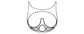
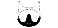
本発明は、医療用インプラントの支持構造体と電界紡糸層(電界紡糸医療用インプラント層)との間に、医療用インプラントの耐久性向上及び摩耗低減を図るための電界紡糸カバー層を有する医療用インプラントを提供する。具体的には、一実施形態では、本発明は、心臓弁用の金属ワイヤ支持構造体(図1)の少なくとも一部を被覆し、かつ、金属ワイヤ支持構造体と、電界紡糸心臓弁または弁葉(310)との間に位置する電界紡糸カバー層(210)を有する、医療用インプラントを提供する。分かりやすくするために、電界紡糸心臓弁または弁葉(leaflet)は図示しておらず、この例では、単に符号310で示している。
The present invention provides a medical implant having an electrospun cover layer between the support structure of the medical implant and the electrospun layer (electrospun medical implant layer) to increase the durability and reduce wear of the medical implant. Specifically, in one embodiment, the present invention provides a medical implant having an electrospun cover layer ( 210 ) that covers at least a portion of a metal wire support structure (FIG. 1) for a heart valve and is located between the metal wire support structure and the electrospun heart valve or leaflet (310) . For clarity, the electrospun heart valve or leaflet is not shown and is simply indicated by the
上述したように、電界紡糸カバー層は、医療用インプラント支持構造体の少なくとも一部を被覆する。心臓弁の例では、心臓弁の支柱(strut)が、摩耗が生じる典型的な領域である。しかし、本開示の医療用インプラントでは、心臓弁用の金属ワイヤ支持構造体(医療用インプラント支持構造体)は、電界紡糸カバー層で被覆されているので、金属ワイヤ支持構造体は、もはや電界紡糸心臓弁(電界紡糸医療用インプラント層)とは直接接触しない。その代わり、電界紡糸心臓弁は、電界紡糸カバー層と直接接触する。 As discussed above, the electrospun cover layer covers at least a portion of the medical implant support structure. In the example of a heart valve, the struts of the heart valve are typical areas where wear occurs. However, in the medical implant of the present disclosure, because the metal wire support structure for the heart valve (medical implant support structure) is covered with the electrospun cover layer, the metal wire support structure is no longer in direct contact with the electrospun heart valve (electrospun medical implant layer). Instead, the electrospun heart valve is in direct contact with the electrospun cover layer.
本発明者らは、電界紡糸カバー層及び電界紡糸医療用インプラント層の2つの電界紡糸層間の摩耗は、電界紡糸されていない他の構造体と、電界紡糸層(電界紡糸ポリマー)との間の摩耗よりも著しく小さいことを見出した。したがって、電界紡糸カバー層は、電界紡糸心臓弁または弁葉の摩耗関連損傷の低減を助け、これにより、耐久性向上が可能になるという結論に達した。 The inventors have found that the wear between the two electrospun layers, the electrospun cover layer and the electrospun medical implant layer, is significantly less than the wear between other non-electrospun structures and the electrospun layer (electrospun polymer). Thus, it has been concluded that the electrospun cover layer helps reduce wear-related damage to the electrospun heart valve or leaflets, thereby allowing for improved durability.
より一般的に言えば、電界紡糸カバー層は、(金属製の)支持構造体を被覆するカバー層、あるいは、該支持構造体を被覆する合成繊維層をさらに被覆するカバー層である。この電界紡糸カバー層は、(金属製の)支持構造体または該支持構造体を被覆する合成繊維層と、心臓弁または弁葉などの電界紡糸層(電界紡糸医療用インプラント層)または動物由来組織層との間に位置する中間層として機能する。 More generally, the electrospun cover layer is a cover layer covering a (metallic) support structure or a synthetic fiber layer covering the support structure. The electrospun cover layer acts as an intermediate layer between the (metallic) support structure or the synthetic fiber layer covering the support structure and an electrospun layer such as a heart valve or valve leaflet (electrospun medical implant layer) or an animal-derived tissue layer.
支持構造体(医療用インプラント支持構造体)は、電界紡糸材料、特に生体吸収性ポリマーからなる層(電界紡糸カバー層)によって直接被覆される。これにより、内因性組織修復(ETR)プロセスを促進し、それと同時に、心臓弁または弁葉の摩耗を防止することができる。電界紡糸カバー層は、生体吸収性及び多孔性を有する材料から形成される。電界紡糸カバー層は、該カバー層の細孔内に細胞及び栄養素が入り込み、その細胞が細孔内で成長することにより、天然組織に吸収され置き換えられる。電界紡糸カバー層の細孔の孔径分布は、5~50μmである。したがって、電界紡糸カバー層は、生体吸収性多孔質電界紡糸カバー層とも称される。 The support structure (medical implant support structure) is directly covered with a layer (electrospun cover layer) of electrospun material, in particular a bioabsorbable polymer. This can promote the endogenous tissue repair (ETR) process and at the same time prevent wear of the heart valve or valve leaflets. The electrospun cover layer is made of a material that is bioabsorbable and porous. The electrospun cover layer is absorbed and replaced by the natural tissue by cells and nutrients entering and growing in the pores of the cover layer. The pores of the electrospun cover layer have a pore size distribution of 5-50 μm. Therefore, the electrospun cover layer is also called a bioabsorbable porous electrospun cover layer.
電界紡糸カバー層の設計は、用途毎に異なり、例えば、心臓弁用の金属ワイヤ支持構造体の支柱(ポスト)を被覆する小さなチューブとして提供することができる。一端が閉じたチューブを使用することにより、支柱を完璧に被覆することができ、これにより、支柱の損傷、摩耗、破壊を防止することができる。加えて、電界紡糸カバー材料(電界紡糸カバー層)は嵩張らないので、最終的なデバイス(医療用インプラント)の全体サイズを小さくすることができる。電界紡糸カバー層の設計の別の選択肢は、シートである。 The electrospun cover layer design varies from application to application and can be provided as a small tube to cover the posts of a metal wire support structure for a heart valve, for example. By using a tube closed at one end, the posts can be completely covered, thereby preventing damage, wear and tear on the posts. In addition, the electrospun cover material (electrospun cover layer) is not bulky, which can reduce the overall size of the final device (medical implant). Another option for the electrospun cover layer design is a sheet.
電界紡糸カバー層をチューブ状に構成する実施形態では、電界紡糸は、大きなマンドレルを使用する代わりに、ワイヤ上に直接行うことができる。この技術により、非常に小さい内径を有する非常に微細なチューブを作製することができる。 In embodiments where the electrospun cover layer is constructed in a tubular shape, electrospinning can be performed directly onto the wire instead of using a large mandrel. This technique can produce very fine tubes with very small inner diameters.
有用な実施形態としては、電界紡糸カバー層を支柱上に直接電界紡糸すること、電界紡糸カバー材料をチューブ状に構成し支柱上に摺動させて取り付けること、電界紡糸カバー材料(例えばシートまたはチューブ)を支柱に接着によって取り付けること、及び、電界紡糸カバー材料(例えばシートまたはチューブ)を支柱に縫合によって直接取り付けること、が挙げられる。 Useful embodiments include electrospun the electrospun cover layer directly onto the support, constructing the electrospun cover material into a tube and sliding it onto the support, gluing the electrospun cover material (e.g., a sheet or tube) to the support, and suturing the electrospun cover material (e.g., a sheet or tube) directly to the support.
本発明において使用される電界紡糸材料は、ウレイド-ピリミジノン(UPy)四重水素結合モチーフ(Sijbesma(1997)、Science278、1601-1604によって開発された)と、ポリマー骨格とを含み得る。そのようなポリマーには、生分解性ポリエステル、ポリウレタン、ポリカーボネート、ポリ(オルトエステル)、ポリホスホエステル、ポリ酸無水物、ポリホスファゼン、ポリヒドロキシアルカノエート、ポリビニルアルコール、及びポリプロピレンフマル酸からなる群から選択される。ポリエステルの例は、ポリカプロラクトン、ポリ(L-ラクチド)、ポリ(DL-ラクチド)、ポリ(バレロラクトン)、ポリグリコリド、ポリジオキサノン、及びそれらのコポリエステルである。ポリカーボネートの例は、ポリ(トリメチレンカーボネート)、ポリ(ジメチルトリメチレンカーボネート)、ポリ(ヘキサメチレンカーボネート)である。 The electrospun materials used in the present invention may include a ureido-pyrimidinone (UPy) quadruple hydrogen bonding motif (developed by Sijbesma (1997), Science 278, 1601-1604) and a polymer backbone. Such polymers are selected from the group consisting of biodegradable polyesters, polyurethanes, polycarbonates, poly(orthoesters), polyphosphoesters, polyanhydrides, polyphosphazenes, polyhydroxyalkanoates, polyvinyl alcohols, and polypropylene fumarates. Examples of polyesters are polycaprolactone, poly(L-lactide), poly(DL-lactide), poly(valerolactone), polyglycolide, polydioxanone, and copolyesters thereof. Examples of polycarbonates are poly(trimethylene carbonate), poly(dimethyltrimethylene carbonate), and poly(hexamethylene carbonate).
材料の特性を注意深く選択し、必要な表面特性が確保されるように材料を加工すれば、代替の非超分子ポリマーを使用しても同様の結果が得られる。そのようなポリマーには、生分解性または非生分解性のポリエステル、ポリウレタン、ポリカーボネート、ポリ(オルトエステル)、ポリホスホエステル、ポリ酸無水物、ポリホスファゼン、ポリヒドロキシアルカノエート、ポリビニルアルコール、ポリプロピレンフマル酸塩が含まれる。ポリエステルの例は、ポリカプロラクトン、ポリ(L-ラクチド)、ポリ(DL-ラクチド)、ポリ(バレロラクトン)、ポリグリコリド、ポリジオキサノン、及びそれらのコポリエステルである。ポリカーボネートの例は、ポリ(トリメチレンカーボネート)、ポリ(ジメチルトリメチレンカーボネート)、ポリ(ヘキサメチレンカーボネート)である。 Alternative non-supramolecular polymers can be used with similar results if the material properties are carefully selected and the material is processed to ensure the required surface properties. Such polymers include biodegradable and non-biodegradable polyesters, polyurethanes, polycarbonates, poly(orthoesters), polyphosphoesters, polyanhydrides, polyphosphazenes, polyhydroxyalkanoates, polyvinyl alcohols, and polypropylene fumarates. Examples of polyesters are polycaprolactone, poly(L-lactide), poly(DL-lactide), poly(valerolactone), polyglycolide, polydioxanone, and their copolyesters. Examples of polycarbonates are poly(trimethylene carbonate), poly(dimethyltrimethylene carbonate), and poly(hexamethylene carbonate).
実験データ Experimental data
本発明者らは、本発明の電界紡糸カバー層と、それと同様の摩耗特性が期待されるポリマー繊維構造体であるePTFEファブリックとについて実験した。すると、驚くべきことに、本発明者らは、下記の表1に示すように、本発明の電界紡糸カバー層は、ePTFEファブリックと比較して有意に改善された結果を示すことを見出した。 The inventors have experimented with the electrospun cover layer of the present invention and ePTFE fabric, a polymer fiber structure that is expected to have similar wear characteristics. Surprisingly, the inventors have found that the electrospun cover layer of the present invention shows significantly improved results compared to ePTFE fabric, as shown in Table 1 below.

加速摩耗試験(AWT)を実施したところ、ePTFEファブリックで被覆されたフレーム(XSAV-158、XSAV-159)を有する弁は、非常に早い段階で故障したが、本発明の電界紡糸カバー層で被覆されたフレーム(XSAV-162、XSAV-163)を有する弁は、ePTFEファブリックで被覆されたフレームと比較してはるかに長く動作した。これは、電界紡糸カバー層でフレームを被覆することにより、耐久性が予想外に向上したことを示す。 When accelerated wear testing (AWT) was performed, valves with frames covered with ePTFE fabric (XSAV-158, XSAV-159) failed at a very early stage, while valves with frames covered with the electrospun cover layer of the present invention (XSAV-162, XSAV-163) operated much longer compared to frames covered with ePTFE fabric. This indicates that covering the frame with an electrospun cover layer unexpectedly improved durability.
Claims (14)
(a)医療用インプラント支持構造体と、
(b)前記医療用インプラント支持構造体の少なくとも一部を被覆する、電界紡糸カバー層と、
(c)前記電界紡糸カバー層を被覆する電界紡糸医療用インプラント層と、を含み、
前記電界紡糸カバー層は、前記医療用インプラント支持構造体の前記少なくとも一部と、前記電界紡糸医療用インプラント層との間に位置する中間層として機能し、これにより、前記医療用インプラント支持構造体が前記電界紡糸医療用インプラント層と直接接触することを防止し、かつ、前記電界紡糸カバー層が前記電界紡糸医療用インプラント層と直接接触することを確実にし、前記電界紡糸医療用インプラント層は、前記電界紡糸カバー層に対して相対的に動くことが可能となるように前記電界紡糸カバー層上に配置される、医療用インプラント。 1. A medical implant, comprising:
(a) a medical implant support structure;
(b) an electrospun cover layer covering at least a portion of the medical implant support structure; and
(c) an electrospun medical implant layer covering the electrospun cover layer;
A medical implant, wherein the electrospun cover layer acts as an intermediate layer between at least a portion of the medical implant support structure and the electrospun medical implant layer, thereby preventing the medical implant support structure from coming into direct contact with the electrospun medical implant layer and ensuring that the electrospun cover layer is in direct contact with the electrospun medical implant layer, the electrospun medical implant layer being positioned on the electrospun cover layer such that it is capable of moving relative to the electrospun cover layer.
前記電界紡糸カバー層は、生体吸収性及び多孔性を有する材料から形成された生体吸収性多孔質電界紡糸カバー層を含む、医療用インプラント。 2. The medical implant of claim 1,
The medical implant, wherein the electrospun cover layer comprises a bioabsorbable porous electrospun cover layer formed from a material that is bioabsorbable and porous.
前記生体吸収性多孔質電界紡糸カバー層は、該カバー層の細孔内に細胞及び栄養素が入り込み、前記細胞が前記細孔内で成長することにより、天然組織に吸収され置き換えられる、医療用インプラント。 3. The medical implant of claim 2,
The bioabsorbable porous electrospun cover layer is absorbed and replaced by natural tissue by allowing cells and nutrients to enter into the pores of the cover layer and for the cells to grow within the pores.
前記電界紡糸カバー層は、多孔質であり、5~50μmの孔径分布を有する、医療用インプラント。 2. The medical implant of claim 1,
A medical implant, wherein said electrospun cover layer is porous and has a pore size distribution of 5-50 μm.
前記電界紡糸医療用インプラント層は、生体吸収性及び多孔性を有する材料から形成された生体吸収性多孔質電界紡糸医療用インプラント層である、医療用インプラント。 2. The medical implant of claim 1,
A medical implant, wherein the electrospun medical implant layer is a bioabsorbable porous electrospun medical implant layer formed from a material having bioabsorbability and porosity.
前記生体吸収性多孔質電界紡糸医療用インプラント層は、該インプラント層の細孔内に細胞及び栄養素が入り込み、前記細胞が前記細孔内で成長することにより、天然組織に吸収され置き換えられる、医療用インプラント。 6. The medical implant of claim 5,
The bioabsorbable porous electrospun medical implant layer allows cells and nutrients to enter into the pores of the implant layer and the cells to grow within the pores, thereby allowing the medical implant to be absorbed and replaced by natural tissue.
前記電界紡糸医療用インプラント層は、多孔質であり、5~50μmの孔径分布を有する、医療用インプラント。 2. The medical implant of claim 1,
The medical implant, wherein said electrospun medical implant layer is porous and has a pore size distribution of 5-50 μm.
前記電界紡糸医療用インプラント層は、心臓の弁または弁葉である、医療用インプラント。 2. The medical implant of claim 1,
A medical implant, wherein said electrospun medical implant layer is a heart valve or leaflet.
前記医療用インプラント支持構造体は、心臓弁用の支柱を有する金属ワイヤ支持構造体である、医療用インプラント。 2. The medical implant of claim 1,
A medical implant, wherein the medical implant support structure is a metal wire support structure having struts for a heart valve.
前記電界紡糸カバー層は、前記金属ワイヤ支持構造体の1または複数の前記支柱を被覆する、医療用インプラント。 10. The medical implant of claim 9,
The medical implant, wherein the electrospun cover layer covers one or more of the struts of the metal wire support structure.
前記電界紡糸カバー層は、前記医療用インプラント支持構造体の前記少なくとも一部に直接的に電界紡糸される、医療用インプラント。 2. The medical implant of claim 1,
The medical implant, wherein said electrospun cover layer is electrospun directly onto said at least a portion of said medical implant support structure.
前記電界紡糸カバー層は、チューブ状に構成され、前記医療用インプラント支持構造体の前記少なくとも一部に摺動させて取り付けられる、医療用インプラント。 2. The medical implant of claim 1,
The medical implant , wherein the electrospun cover layer is configured as a tube and is slidingly attached to the at least a portion of the medical implant support structure.
前記電界紡糸カバー層は、前記医療用インプラント支持構造体の前記少なくとも一部に縫合によって取り付けられる、医療用インプラント。 2. The medical implant of claim 1,
The medical implant, wherein the electrospun cover layer is attached to the at least a portion of the medical implant support structure by sutures.
前記電界紡糸カバー層は、前記医療用インプラント支持構造体の前記少なくとも一部に接着によって取り付けられる、医療用インプラント。 2. The medical implant of claim 1,
The medical implant, wherein the electrospun cover layer is adhesively attached to the at least a portion of the medical implant support structure.
Applications Claiming Priority (3)
| Application Number | Priority Date | Filing Date | Title |
|---|---|---|---|
| US201962798227P | 2019-01-29 | 2019-01-29 | |
| US62/798,227 | 2019-01-29 | ||
| PCT/EP2019/084147 WO2020156711A1 (en) | 2019-01-29 | 2019-12-09 | Electrospun cover layer for medical implants |
Publications (2)
| Publication Number | Publication Date |
|---|---|
| JP2022518470A JP2022518470A (en) | 2022-03-15 |
| JP7568630B2 true JP7568630B2 (en) | 2024-10-16 |
Family
ID=68841108
Family Applications (1)
| Application Number | Title | Priority Date | Filing Date |
|---|---|---|---|
| JP2021541628A Active JP7568630B2 (en) | 2019-01-29 | 2019-12-09 | Electrospun cover layers for medical implants |
Country Status (5)
| Country | Link |
|---|---|
| US (1) | US20220088273A1 (en) |
| EP (1) | EP3917585A1 (en) |
| JP (1) | JP7568630B2 (en) |
| CN (1) | CN113365671B (en) |
| WO (1) | WO2020156711A1 (en) |
Families Citing this family (2)
| Publication number | Priority date | Publication date | Assignee | Title |
|---|---|---|---|---|
| WO2024123920A1 (en) | 2022-12-06 | 2024-06-13 | Medical 21, Inc. | Composite implant |
| WO2025093685A1 (en) | 2023-10-31 | 2025-05-08 | Stentit Bv | Fibrillated mesh for a medical implant and medical implant including the same |
Citations (5)
| Publication number | Priority date | Publication date | Assignee | Title |
|---|---|---|---|---|
| JP2014508555A (en) | 2010-12-21 | 2014-04-10 | プロストヘクシス ピーティワイ リミテッド | Methods for implanting artificial meniscus and human knee joint |
| JP2015515322A (en) | 2012-04-05 | 2015-05-28 | ゼウス インダストリアル プロダクツ インコーポレイテッド | Artificial composite device |
| JP2016512065A (en) | 2013-03-13 | 2016-04-25 | ダブリュ.エル.ゴア アンド アソシエイツ,インコーポレイティドW.L. Gore & Associates, Incorporated | Durable high-strength polymer composite suitable for implants and articles made from the polymer composite |
| US20160317295A1 (en) | 2015-04-30 | 2016-11-03 | Mayo Foundation For Medical Education And Research | Nanofibrous biologic heart valve leaflets and fibrosa layer of a leaflet |
| US20170340460A1 (en) | 2016-05-31 | 2017-11-30 | V-Wave Ltd. | Systems and methods for making encapsulated hourglass shaped stents |
Family Cites Families (9)
| Publication number | Priority date | Publication date | Assignee | Title |
|---|---|---|---|---|
| WO1997024989A1 (en) * | 1996-01-04 | 1997-07-17 | Shelhigh, Inc. | Heart valve prosthesis and method for making same |
| CA2602050C (en) * | 2005-03-11 | 2013-12-03 | Wake Forest University Health Sciences | Production of tissue engineered heart valves |
| US20150265744A1 (en) * | 2008-10-09 | 2015-09-24 | Technische Universiteit Eindhoven | Multilayer preform obtained by electro-spinning, method for producing a preform as well as use thereof |
| US8945209B2 (en) * | 2011-05-20 | 2015-02-03 | Edwards Lifesciences Corporation | Encapsulated heart valve |
| CN202589707U (en) * | 2012-05-24 | 2012-12-12 | 上海欣吉特生物科技有限公司 | Artificial heart valve |
| NL2009145C2 (en) * | 2012-07-06 | 2014-01-07 | Xeltis B V | Implant. |
| US10232564B2 (en) * | 2015-04-29 | 2019-03-19 | Edwards Lifesciences Corporation | Laminated sealing member for prosthetic heart valve |
| US10631977B2 (en) * | 2015-08-24 | 2020-04-28 | Edwards Lifesciences Corporation | Covering and assembly method for transcatheter valve |
| US11185406B2 (en) * | 2017-01-23 | 2021-11-30 | Edwards Lifesciences Corporation | Covered prosthetic heart valve |
-
2019
- 2019-12-09 JP JP2021541628A patent/JP7568630B2/en active Active
- 2019-12-09 WO PCT/EP2019/084147 patent/WO2020156711A1/en not_active Ceased
- 2019-12-09 CN CN201980090659.1A patent/CN113365671B/en active Active
- 2019-12-09 EP EP19817665.3A patent/EP3917585A1/en active Pending
- 2019-12-09 US US17/425,175 patent/US20220088273A1/en active Pending
Patent Citations (5)
| Publication number | Priority date | Publication date | Assignee | Title |
|---|---|---|---|---|
| JP2014508555A (en) | 2010-12-21 | 2014-04-10 | プロストヘクシス ピーティワイ リミテッド | Methods for implanting artificial meniscus and human knee joint |
| JP2015515322A (en) | 2012-04-05 | 2015-05-28 | ゼウス インダストリアル プロダクツ インコーポレイテッド | Artificial composite device |
| JP2016512065A (en) | 2013-03-13 | 2016-04-25 | ダブリュ.エル.ゴア アンド アソシエイツ,インコーポレイティドW.L. Gore & Associates, Incorporated | Durable high-strength polymer composite suitable for implants and articles made from the polymer composite |
| US20160317295A1 (en) | 2015-04-30 | 2016-11-03 | Mayo Foundation For Medical Education And Research | Nanofibrous biologic heart valve leaflets and fibrosa layer of a leaflet |
| US20170340460A1 (en) | 2016-05-31 | 2017-11-30 | V-Wave Ltd. | Systems and methods for making encapsulated hourglass shaped stents |
Also Published As
| Publication number | Publication date |
|---|---|
| US20220088273A1 (en) | 2022-03-24 |
| EP3917585A1 (en) | 2021-12-08 |
| CN113365671A (en) | 2021-09-07 |
| JP2022518470A (en) | 2022-03-15 |
| WO2020156711A1 (en) | 2020-08-06 |
| CN113365671B (en) | 2022-09-27 |
Similar Documents
| Publication | Publication Date | Title |
|---|---|---|
| AU2022204333B2 (en) | Improvements for prosthetic valves and related inventions | |
| Aguiari et al. | Mechanical testing of pericardium for manufacturing prosthetic heart valves | |
| EP1968660B1 (en) | Biodegradable scaffold | |
| Bui et al. | Transcatheter heart valves: a biomaterials perspective | |
| US20170112620A1 (en) | Systems and methods of sealing a deployed valve component | |
| US11833273B2 (en) | Leaflet thickness via stretching techniques for improved valve durability | |
| CN113365671B (en) | Electrospun cover layer for medical implants | |
| CN114080199B (en) | Electrospun heart valves | |
| JP7317966B2 (en) | electrospun suture ring | |
| JP7711065B2 (en) | Multilayer electrospun heart valve leaflets |
Legal Events
| Date | Code | Title | Description |
|---|---|---|---|
| A621 | Written request for application examination |
Free format text: JAPANESE INTERMEDIATE CODE: A621 Effective date: 20220826 |
|
| A131 | Notification of reasons for refusal |
Free format text: JAPANESE INTERMEDIATE CODE: A131 Effective date: 20230606 |
|
| A521 | Request for written amendment filed |
Free format text: JAPANESE INTERMEDIATE CODE: A523 Effective date: 20230828 |
|
| A131 | Notification of reasons for refusal |
Free format text: JAPANESE INTERMEDIATE CODE: A131 Effective date: 20231212 |
|
| A521 | Request for written amendment filed |
Free format text: JAPANESE INTERMEDIATE CODE: A523 Effective date: 20240227 |
|
| A131 | Notification of reasons for refusal |
Free format text: JAPANESE INTERMEDIATE CODE: A131 Effective date: 20240528 |
|
| A521 | Request for written amendment filed |
Free format text: JAPANESE INTERMEDIATE CODE: A523 Effective date: 20240607 |
|
| TRDD | Decision of grant or rejection written | ||
| A01 | Written decision to grant a patent or to grant a registration (utility model) |
Free format text: JAPANESE INTERMEDIATE CODE: A01 Effective date: 20240917 |
|
| A61 | First payment of annual fees (during grant procedure) |
Free format text: JAPANESE INTERMEDIATE CODE: A61 Effective date: 20241003 |
|
| R150 | Certificate of patent or registration of utility model |
Ref document number: 7568630 Country of ref document: JP Free format text: JAPANESE INTERMEDIATE CODE: R150 |