JP7581375B2 - Gas Treatment Equipment - Google Patents
Gas Treatment Equipment Download PDFInfo
- Publication number
- JP7581375B2 JP7581375B2 JP2022565380A JP2022565380A JP7581375B2 JP 7581375 B2 JP7581375 B2 JP 7581375B2 JP 2022565380 A JP2022565380 A JP 2022565380A JP 2022565380 A JP2022565380 A JP 2022565380A JP 7581375 B2 JP7581375 B2 JP 7581375B2
- Authority
- JP
- Japan
- Prior art keywords
- flow path
- electrode
- gas
- path section
- treatment device
- Prior art date
- Legal status (The legal status is an assumption and is not a legal conclusion. Google has not performed a legal analysis and makes no representation as to the accuracy of the status listed.)
- Active
Links
Images





Classifications
-
- B—PERFORMING OPERATIONS; TRANSPORTING
- B01—PHYSICAL OR CHEMICAL PROCESSES OR APPARATUS IN GENERAL
- B01J—CHEMICAL OR PHYSICAL PROCESSES, e.g. CATALYSIS OR COLLOID CHEMISTRY; THEIR RELEVANT APPARATUS
- B01J19/00—Chemical, physical or physico-chemical processes in general; Their relevant apparatus
- B01J19/08—Processes employing the direct application of electric or wave energy, or particle radiation; Apparatus therefor
-
- H—ELECTRICITY
- H05—ELECTRIC TECHNIQUES NOT OTHERWISE PROVIDED FOR
- H05H—PLASMA TECHNIQUE; PRODUCTION OF ACCELERATED ELECTRICALLY-CHARGED PARTICLES OR OF NEUTRONS; PRODUCTION OR ACCELERATION OF NEUTRAL MOLECULAR OR ATOMIC BEAMS
- H05H1/00—Generating plasma; Handling plasma
- H05H1/24—Generating plasma
Landscapes
- Physics & Mathematics (AREA)
- Engineering & Computer Science (AREA)
- Plasma & Fusion (AREA)
- Chemical & Material Sciences (AREA)
- Spectroscopy & Molecular Physics (AREA)
- Health & Medical Sciences (AREA)
- General Health & Medical Sciences (AREA)
- Toxicology (AREA)
- Organic Chemistry (AREA)
- Chemical Kinetics & Catalysis (AREA)
- Plasma Technology (AREA)
- Physical Or Chemical Processes And Apparatus (AREA)
Description
本開示は、気体処理装置に関する。 The present disclosure relates to a gas treatment device.
従来、気体をプラズマ処理する気体処理装置が知られている。たとえば、特許文献1には、プラズマCVD装置のクリーニングで発生したフッ素系ガスをプラズマによって分解する気体処理装置が開示されている。Conventionally, gas processing apparatuses that perform plasma processing of gases are known. For example,
本開示の一態様による気体処理装置は、基体と、複数の電極とを有する。基体は、セラミックスからなり、気体の導入口および排出口、ならびに、導入口と排出口とを繋ぐ内部流路を有する。複数の電極は、基体の内部に位置する。また、内部流路は、第1流路部と、第2流路部とを有する。第1流路部は、導入口から導入される気体の流れ方向である第1方向に沿って延びる。第2流路部は、第1方向と異なる第2方向に沿って延びる。また、複数の電極は、第2流路部を挟むように位置し、第2流路部に沿って延びる。A gas treatment device according to one aspect of the present disclosure has a base and a plurality of electrodes. The base is made of ceramics and has a gas inlet and outlet, as well as an internal flow path connecting the inlet and outlet. The plurality of electrodes are located inside the base. The internal flow path has a first flow path section and a second flow path section. The first flow path section extends along a first direction, which is the flow direction of the gas introduced from the inlet. The second flow path section extends along a second direction different from the first direction. The plurality of electrodes are located on either side of the second flow path section and extend along the second flow path section.
以下に、本開示による気体処理装置を実施するための形態(以下、「実施形態」と記載する)について図面を参照しつつ詳細に説明する。なお、この実施形態により本開示が限定されるものではない。また、各実施形態は、処理内容を矛盾させない範囲で適宜組み合わせることが可能である。また、以下の各実施形態において同一の部位には同一の符号を付し、重複する説明は省略される。 Below, a detailed description will be given of a form for implementing a gas treatment device according to the present disclosure (hereinafter, referred to as an "embodiment") with reference to the drawings. Note that the present disclosure is not limited to this embodiment. Furthermore, each embodiment can be appropriately combined as long as the processing content is not contradictory. Furthermore, the same parts in each of the following embodiments are given the same reference numerals, and duplicate explanations will be omitted.
また、以下に示す実施形態では、「一定」、「直交」、「垂直」あるいは「平行」といった表現が用いられる場合があるが、これらの表現は、厳密に「一定」、「直交」、「垂直」あるいは「平行」であることを要しない。すなわち、上記した各表現は、たとえば製造精度、設置精度などのずれを許容するものとする。In addition, in the embodiments described below, expressions such as "constant," "orthogonal," "vertical," and "parallel" may be used, but these expressions do not necessarily mean "constant," "orthogonal," "vertical," or "parallel" in the strict sense. In other words, each of the above expressions allows for deviations due to, for example, manufacturing precision, installation precision, and the like.
また、以下参照する各図面では、説明を分かりやすくするために、互いに直交するX軸方向、Y軸方向およびZ軸方向を規定し、Z軸正方向を鉛直上向き方向とする直交座標系を示す場合がある。また、鉛直軸を回転中心とする回転方向をθ方向と呼ぶ場合がある。In addition, in the drawings referred to below, for ease of understanding, an orthogonal coordinate system may be shown in which the X-axis, Y-axis, and Z-axis directions are defined as being orthogonal to each other, with the positive Z-axis direction being the vertically upward direction. The direction of rotation about the vertical axis may be referred to as the θ direction.
従来、気体をプラズマ処理する気体処理装置が知られている。この種の気体処理装置においては、プラズマ処理の処理効率の向上が期待されている。Conventionally, gas treatment devices that perform plasma treatment on gases have been known. With this type of gas treatment device, it is expected that the processing efficiency of plasma treatment will be improved.
(第1実施形態)
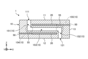
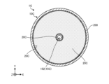
第1実施形態に係る気体処理装置の構成について図1および図2を参照して説明する。図1は、第1実施形態に係る気体処理装置の模式的な斜視図である。また、図2は、第1実施形態に係る気体処理装置の模式的な断面図である。なお、図2には、図1に示すII-II線で気体処理装置を垂直に切断した断面図(XZ断面図)を示している。II-II線は、基体処理装置の平面視において後述する気体の導入口111および排出口121を通る直線である。
First Embodiment
The configuration of the gas processing apparatus according to the first embodiment will be described with reference to Fig. 1 and Fig. 2. Fig. 1 is a schematic perspective view of the gas processing apparatus according to the first embodiment. Fig. 2 is a schematic cross-sectional view of the gas processing apparatus according to the first embodiment. Fig. 2 shows a cross-sectional view (XZ cross-sectional view) of the gas processing apparatus cut vertically along line II-II shown in Fig. 1. Line II-II is a straight line passing through a
図1および図2に示すように、第1実施形態に係る気体処理装置1は、内部流路15を有する基体10と、複数の電極20と、複数の外部電極50と、複数の接続導体55とを有していてもよい。気体処理装置1は、複数の電極20間の放電によってプラズマを発生させることにより、内部流路15を流れる気体を処理する。1 and 2, the
基体10は、セラミックスからなる。セラミックスとしては、たとえば、酸化アルミニウム質セラミックス、酸化イットリウム質セラミックス、酸化ジルコニウム質セラミックス、炭化珪素質セラミックス、コージェライト質セラミックス、窒化珪素質セラミックス、窒化アルミニウム質セラミックスおよびムライト質セラミックス等が挙げられる。これらのセラミックスは、耐薬品性や機械的強度に優れる。したがって、これらのセラミックスからなる基体10を有する気体処理装置1は、信頼性が高い。また、酸化アルミニウム質セラミックスからなる基体10を有する気体処理装置1は、加工性に優れ、かつ安価である。The
基体10は、たとえば円柱状の外形を有していてもよい。具体的には、基体10は、平面視円形の第1面11(ここでは、上面)および第2面12(ここでは、下面)と、これら第1面11および第2面12を繋ぐ第3面13(ここでは、側面)とを有していてもよい。なお、基体10の外形は、必ずしも円柱状であることを要しない。たとえば、基体10の外形は、板状であってもよい。The
基体10の第1面11には、気体の導入口111が位置していてもよい。また、基体10の第2面12には、気体の排出口121が位置していてもよい。A
基体10は、内部流路15を有していてもよい。内部流路15は、基体10の内部に位置しており、導入口111と排出口121とを繋ぐ。The
具体的には、内部流路15は、導入口側第1流路部151と、排出口側第1流路部152と、第2流路部153とを有していてもよい。Specifically, the
導入口側第1流路部151は、導入口111に連通する。導入口側第1流路部151は、導入口111から導入される気体の流れ方向である第1方向(ここでは、鉛直方向)に沿って延びていてもよい。また、排出口側第1流路部152は、排出口121に連通する。排出口側第1流路部152は、導入口側第1流路部151と同様に第1方向に沿って延びていてもよい。The inlet side first
一方、第2流路部153は、第1方向とは異なる方向に沿って延びていてもよい。具体的には、第2流路部153は、第1方向と直交する方向(ここでは、水平方向)に沿って延びていてもよい。かかる第2流路部153は、導入口側第1流路部151と排出口側第1流路部152との間に位置していてもよい。この場合、第2流路部153は、これら導入口側第1流路部151および排出口側第1流路部152を繋ぐ。なお、第2方向は、少なくとも第1方向と異なっていれば良く、必ずしも第1方向と直交することを要しない。On the other hand, the second
導入口111から内部流路15に導入された気体は、まず、導入口側第1流路部151を第1方向に沿って流れる。その後、気体は、導入口側第1流路部151と第2流路部153との接続部である第1屈曲部154において流れ方向を第2方向に変えて第2流路部153を流れる。そして、気体は、第2流路部153と排出口側第1流路部152との接続部である第2屈曲部155において流れ方向を再度第1方向に変えて排出口側第1流路部152を流れて、排出口121から排出される。The gas introduced into the
複数の電極20は、基体10の内部に位置する。具体的には、第1実施形態に係る気体処理装置1は、一対の電極20,20を有していてもよい。一対の電極20,20は、第2流路部153を挟むように位置し、第2流路部153と平行に延びる。一対の電極20,20のうち一つは、基体10の第1面11と第2流路部153との間に位置していてもよい。また、一対の電極20,20のうち残りの一つは、基体10の第2面12と第2流路部153との間に位置する。The
一対の電極20,20に電圧が印加されると、一対の電極20,20によって挟まれた第2流路部153内で放電が起きる。これにより、第2流路部153を流れる気体がプラズマ処理される。気体処理装置1は、基体10の内部に内部流路15を有するため、プラズマ密度の維持が容易である。When a voltage is applied to the pair of
一対の電極20,20は、基体10を構成するセラミックス中に埋設されており、内部流路15に露出していない。したがって、一対の電極20,20は、内部流路15を流れる気体と接触するおそれがない。したがって、内部流路15を流れる気体によって一対の電極20,20が腐食または破損したり、内部流路15を流れる気体に電極20の一部(欠片等)が混入したりすることがない。The pair of
電極20は、接続導体55、外部電極50および配線部材101を介して外部電源100と接続されてもよい。ここでは、外部電極50が、基体10の第3面13に位置する場合の例を示したが、外部電極50は、基体10の第1面11に位置していてもよい。このように、外部電極50は、基体10の第1面11または第3面13面、すなわち、排出口121が位置する第2面12以外の面に位置していてもよい。かかる構成によれば、排出口121から排出される気体に影響を与えることなく、あるいは、排出口121から排出される気体に影響を受けることなく、電極20と外部電源100とを接続することができる。The
電極20の材質としては、導電性の材質であればよい。たとえば、電極20の材質としては、タングステン、モリブデン、チタン、白金、金、銀、銅およびニッケル等を用いることができる。The material of the
外部電極50および接続導体55は、外部電源100から電極20に電圧を印加するための導電路として機能する。外部電極50は、接続導体55を介して電極20に接続されるとともに、配線部材101を介して外部電源100に接続される。接続導体55は、その両端部のうち第1端部が電極20に接続され、第2端部が外部電極50に接続される。The
なお、電極20の端部、具体的には、導入口側第1流路部151または排出口側第1流路部152と対向する端部とは反対側の端部は、基体10の第3面13から露出していてもよい。この場合、接続導体55を介すことなく電極20と外部電極50とを接続することができる。In addition, the end of the
一対の電極20,20に対する電圧の印加方法は、用途等に応じて適宜に設定されてよい。たとえば、一対の電極20,20に対する電圧の印加方法としては、交互に電圧を印加する方法であってもよい。また、一方を印加電極とし、他方を接地電極とする方法であってもよい。この場合、たとえば、基体10の第1面11と第2流路部153との間に位置する電極20を印加電極とし、基体10の第2面12と第2流路部153との間に位置する電極20を接地電極としてもよい。The method of applying a voltage to the pair of
ここでは、基体10の第1面11と第2流路部153との間に1つの電極20が位置する場合の例を示した。これに限らず、気体処理装置1は、基体10の第1面11と第2流路部153との間に、第2流路部153に沿って位置する複数の電極20を有していてもよい。基体10の第2面12と第2流路部153との間に位置する電極20についても同様である。すなわち、気体処理装置1は、基体10の第2面12と第2流路部153との間に、第2流路部153に沿って位置する複数の電極20を有していてもよい。Here, an example is shown in which one
内部流路15を流れる気体は、第1屈曲部154において第1方向(鉛直方向)から第2方向(水平方向)に流れ方向が変化するのに伴って速度が低下する。この結果、第2流路部153における単位体積あたりの気体の滞留時間は、導入口側第1流路部151における単位体積あたりの気体の滞留時間よりも長くなる。これにより、導入口側第1流路部151を挟む位置に複数の電極20を設けた場合と比較して、気体をより長時間プラズマ処理することができる。したがって、第1実施形態に係る気体処理装置1によれば、プラズマ処理の効率を向上させることができる。The gas flowing through the
また、第1実施形態に係る気体処理装置1は、第2流路部153の下流に、第1方向に沿って延びる排出口側第1流路部152を有していてもよい。この場合、内部流路15を流れる気体は、第2流路部153と排出口側第1流路部152との接続部分である第2屈曲部155において第2方向(水平方向)から第1方向(鉛直方向)に流れ方向が変化するのに伴って速度が低下する。これにより、第2流路部153を流れる気体は、第2流路部153により留まりやすくなる。したがって、排出口側第1流路部152を有しない構成、すなわち、たとえば基体10の第3面13に排出口を設けて第2流路部153と接続した構成と比較して、プラズマ処理の効率をさらに向上させることができる。
The
(第2実施形態)
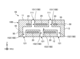
次に、第2実施形態に係る気体処理装置の構成について図3を参照して説明する。図3は、第2実施形態に係る気体処理装置の模式的な断面図である。
Second Embodiment
Next, the configuration of a gas treatment device according to a second embodiment will be described with reference to Fig. 3. Fig. 3 is a schematic cross-sectional view of the gas treatment device according to the second embodiment.
図3に示すように、気体処理装置1Aの基体10Aは、複数の導入口111を有していてもよい。かかる構成によれば、より多くの気体を内部流路15に導入することができるため、プラズマ処理の効率をさらに向上させることができる。As shown in Figure 3, the
図3に示す例において、内部流路15Aは、複数の導入口側第1流路部151と、1つの排出口側第1流路部152と、1つの第2流路部153とを有していてもよい。第2流路部153は、複数の導入口側第1流路部151と、1つの排出口側第1流路部152とを繋ぐ。図3に示す断面視において、複数(ここでは、2つ)の導入口側第1流路部151は、第2流路部153の水平方向両端部に接続され、排出口側第1流路部152は、第2流路部153の水平方向中央部に接続される。In the example shown in FIG. 3, the
また、図3に示す断面視において、気体処理装置1Aは、基体10Aの第1面11と第2流路部153との間に1つの電極20を有するとともに、基体10Aの第2面12と第2流路部153との間に2つの電極20を有していてもよい。これら2つの電極20は、排出口側第1流路部152を挟むように位置している。なお、これに限らず、基体10Aの第2面12と第2流路部153との間に電極20は、一体であってもよい。すなわち、図3に示す断面において2つに見える電極20は、図3に示す断面とは別の断面で気体処理装置1Aを切断した場合に、1つに繋がっていてもよい。3, the
第2実施形態に係る気体処理装置1Aは、たとえば、複数の導入口111から異なる複数の気体を内部流路15Aに導入させて、第2流路部153においてプラズマ処理することによって、これら複数の気体を反応させることも可能である。The
(第3実施形態)
次に、第3実施形態に係る気体処理装置の構成について図4を参照して説明する。図4は、第3実施形態に係る気体処理装置の模式的な断面図である。
Third Embodiment
Next, the configuration of a gas treatment device according to a third embodiment will be described with reference to Fig. 4. Fig. 4 is a schematic cross-sectional view of the gas treatment device according to the third embodiment.
図4に示すように、気体処理装置1Bの基体10Bは、複数の導入口111および複数の排出口121を有していてもよい。かかる構成によれば、プラズマ処理された気体を広範囲に排出することができる。As shown in Figure 4, the
図4に示す例において、内部流路15Bは、たとえば、複数の導入口側第1流路部151と、複数の排出口側第1流路部152と、1つの第2流路部153とを有していてもよい。第2流路部153は、複数の導入口側第1流路部151と、複数の排出口側第1流路部152とを繋ぐ。図4に示す断面視において、複数(ここでは、3つ)の排出口側第1流路部152は、第2流路部153の水平方向両端部および水平方向中央部に接続される。また、図4に示す断面視において、複数(ここでは、2つ)の導入口側第1流路部151は、隣り合う2つの排出口側第1流路部152の間において第2流路部153に接続される。In the example shown in FIG. 4, the
また、図4に示す断面視において、気体処理装置1Bは、基体10Bの第1面11と第2流路部153との間に複数(ここでは、3つ)の電極20を有するとともに、基体10Bの第2面12と第2流路部153との間に複数(ここでは、2つ)の電極20を有していてもよい。なお、基体10Bの第1面11と第2流路部153との間に位置する複数の電極20は、一体であってもよい。同様に、基体10Bの第2面12と第2流路部153との間に位置する複数の電極20は、一体であってもよい。4, the
また、図4には、2つの導入口111が示されているが、気体処理装置1Bは、3つ以上の導入口111を有していてもよい。同様に、図4には、3つの排出口121が示されているが、気体処理装置1Bは、2つまたは4つ以上の排出口121を有していてもよい。
Although two
(第4実施形態)
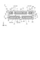
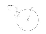
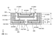
次に、第4実施形態に係る気体処理装置の構成について図5~図10を参照して説明する。図5は、第4実施形態に係る気体処理装置の模式的な断面図である。図6は、第4実施形態に係る気体処理装置の模式的な平面図である。図7は、第4実施形態に係る気体処理装置の模式的な底面図である。図8は、図5に示すVIII-VIII線矢視における模式的な断面図である。図9は、図5に示すIX-IX線矢視における模式的な断面図である。図10は、図5に示すX-X線矢視における模式的な断面図である。なお、図5に示す断面図は、図6に示すV-V線矢視における断面図に相当する。
Fourth Embodiment
Next, the configuration of the gas treatment device according to the fourth embodiment will be described with reference to FIGS. 5 to 10. FIG. 5 is a schematic cross-sectional view of the gas treatment device according to the fourth embodiment. FIG. 6 is a schematic plan view of the gas treatment device according to the fourth embodiment. FIG. 7 is a schematic bottom view of the gas treatment device according to the fourth embodiment. FIG. 8 is a schematic cross-sectional view taken along the line VIII-VIII in FIG. 5. FIG. 9 is a schematic cross-sectional view taken along the line IX-IX in FIG. 5. FIG. 10 is a schematic cross-sectional view taken along the line X-X in FIG. 5. The cross-sectional view shown in FIG. 5 corresponds to the cross-sectional view taken along the line V-V in FIG. 6.
図5~図10に示すように、第4実施形態に係る気体処理装置1Cは、基体10Cと、複数の電極20Cとを有していてもよい。基体10Cは、4つの導入口111(図6参照)と、1つの排出口121(図7参照)とを有していてもよい。なお、基体10Cが有する導入口111の数は、4つに限定されない。基体10Cが有する導入口111は、たとえば1つであってもよいし、5つ以上であってもよい。また、基体10Cは、2つ以上の排出口121を有していてもよい。
As shown in Figures 5 to 10, the
電極20Cは、内部に空間(以下、「内部空間30」と記載する)を有していてもよい。内部空間30は、電極20Cに沿って延びている。言い換えれば、内部空間30は、第2流路部153に沿って延びている。The
このように、電極20Cは、内部空間30を有していてもよい。電極20Cは、たとえばプラズマ処理によって基体10Cの温度が高くなった場合に、熱膨張する。内部空間30を有する電極20Cは、内部空間30によって熱膨張が緩和されることから、内部空間を有しない電極と比較して、電極20Cと基体10Cとの熱膨張係数差による亀裂等の発生を抑制することができる。これにより、気体処理装置1Cの信頼性を向上させることができる。In this way, the
また、第4実施形態に係る気体処理装置1Cは、内部空間30と基体10Cとの間に電極20Cが位置しており、基体10Cと電極20Cと内部空間30とが接する箇所が無いため、電界集中が生じにくい。これにより、異常放電が抑制されることから、気体処理装置1Cの信頼性を向上することができる。In addition, in the
図8~図10に示すように、第4実施形態に係る内部流路15Cは、4つの導入口側第1流路部151(図8参照)と、1つの第2流路部153(図9参照)と、1つの排出口側第1流路部152(図10参照)とを有していてもよい。As shown in Figures 8 to 10, the
図9に示すように、基体10Cを第2方向と平行な面(水平面)で切断した平断面視において、第2流路部153は、第2方向(水平方向)における一方向(たとえばX軸方向またはY軸方向)にのみ延びているのではなく、第2方向における全方向に空間的に広がっている。かかる第2流路部153は、導入口側第1流路部151と比べて容積が大きいことから、気体を滞留させる空間として機能する。すなわち、第4実施形態に係る内部流路15Cは、気体が導入口側第1流路部151から第2流路部153に流入した際に、気体の速度を十分に低下させることができる。したがって、気体をより長時間プラズマ処理することができる。9, in a planar cross-sectional view of the
また、図8~図10に示すように、第2方向(水平方向)における一対の電極20C,20Cの外縁200と、第2方向における第2流路部153の外縁150とは、平断面視において概ね一致する。このように、第2流路部153は、一対の電極20C,20Cによってほぼ全域が挟まれているため、プラズマ処理の効率をさらに向上させることができる。8 to 10, the
電極20Cは、内部空間30を構成する基体10Cの内壁面の全てを覆っていてもよい。このような電極20Cとしては、たとえばメッキ膜が用いられ得る。The
なお、電極20Cの外縁200は、基体10Cの第3面13から露出していてもよい。この場合、接続導体55を介すことなく電極20と外部電極50とを接続することができる。また、ここでは、外部電極50が基体10Cの第3面13に位置する場合の例を示したが、外部電極50は、基体10Cの第1面11に位置していてもよい。The
(第5実施形態)
次に、第5実施形態に係る気体処理装置の構成について図11を参照して説明する。図11は、第5実施形態に係る気体処理装置の模式的な断面図である。
Fifth Embodiment
Next, the configuration of a gas treatment device according to a fifth embodiment will be described with reference to Fig. 11. Fig. 11 is a schematic cross-sectional view of the gas treatment device according to the fifth embodiment.
図11に示すように、第5実施形態に係る気体処理装置1Dは、基体10Dと、複数の電極20Dとを有していてもよい。As shown in FIG. 11, the
基体10Dは、たとえば第2実施形態に係る基体10Aと同様、複数の導入口111と、1つの排出口121とを有していてもよい。また、基体10Dは、内部流路15Dを有していてもよい。内部流路15Dは、たとえば第2実施形態に係る内部流路15Aと同様、複数の導入口側第1流路部151と、1つの排出口側第1流路部152と、1つの第2流路部153とを有していてもよい。なお、本例に限らず、基体10Dは、たとえば第1実施形態に係る基体10、第3実施形態に係る基体10B、第4実施形態に係る基体10Cと同様の構成であってもよい。The
電極20Dは、導入口側第1流路部151に沿って延びる第1電極部21と、第2流路部153に沿って延びる第2電極部22とを有していてもよい。一対の電極20D,20Dにおける第1電極部21同士は、導入口側第1流路部151を挟むように位置している。また、一対の電極20D,20Dにおける第2電極部22同士は、第2流路部153を挟むように位置している。
The
このように、複数の電極20Dは、導入口側第1流路部151を挟むように位置し、導入口側第1流路部151と平行に延びる一対の第1電極部21,21と、第2流路部153を挟むように位置し、第2流路部153に沿って延びる一対の第2電極部22,22とを有していてもよい。かかる構成によれば、第2流路部153だけでなく、導入口側第1流路部151においても気体をプラズマ処理することができるため、プラズマ処理の効率をさらに向上させることができる。In this way, the
また、第1電極部21と第2電極部22とは、繋がっていてもよい。かかる構成によれば、導入口側第1流路部151と第2流路部153との接続部分である第1屈曲部154においても気体をプラズマ処理することができるため、プラズマ処理の効率をさらに向上させることができる。
The
電極20Dは、第2電極部22の端部において基体10Dの第1面11に露出していてもよい。かかる構成によれば、たとえば、接続導体55を用いることなく電極20Dを外部電源100と接続することができる。The
また、電極20Dが有する内部空間30Dも、第2流路部153に沿って延びるとともに、導入口側第1流路部151に沿って延びており、その端部において基体10Dの第1面11に露出している。In addition, the
このように、内部空間30Dは、外部と連通していてもよい。かかる構成によれば、たとえば、外部から内部空間30Dに対して温調流体を供給することが可能である。内部空間30Dに温調流体を供給することで、基体10Dの温度を調整することができるため、プラズマ処理の効率を向上させることができる。また、内部空間30Dに温調流体を供給することで、電極20Dを冷却することができるため、基体10Dと電極20Dとの熱膨張係数差による亀裂の発生を好適に抑制することができる。このため、気体処理装置1Dの信頼性を向上させることができる。In this way, the
基体10Dの厚みT1、電極20Dの厚みT2および内部空間30Dの厚みT3は、用途に応じて適宜定めることができる。一例として、基体10Dの厚みT1は、1mm以上20mm以下であってもよい。また、電極20Dの厚みT2は、100μm以上4mm以下であってもよい。また、内部空間30Dの厚みT3は、0.5mm以上2mm以下であってもよい。厚みT1,T2については、第1~第4実施形態に係る基体10,10A~10Cについても同様である。また、厚みT3については、第4実施形態に係る基体10Cについても同様である。The thickness T1 of the
上述してきた気体処理装置1,1A~1Dは、たとえば電子部品製造分野、エネルギー分野および医療分野等において用いられ得る。電子部品製造分野における用途としては、たとえば、プロセスガスや表面改質ガスなどのプラズマアシスト、アッシング用酸素ガスのオゾン化、アンモニアガスやシアンガスなどのプラズマ分解による水素イオン生成、フッ素系ガスのプラズマ分解等が挙げられる。さらに、ALD(atomic layer deposition)膜の酸素源や洗浄用のオゾンの製造にも用いることができる。また、エネルギー分野における用途としては、たとえば、アンモニアガスのプラズマ分解による水素ガス生成等が挙げられる。また、医療分野における用途としては、たとえば、プラズマ洗浄装置に用いる希ガスおよび窒素ガス等の不活性ガスあるいは大気のプラズマアシスト、遺伝子導入装置に用いる希ガスのプラズマアシスト等が挙げられる。The
(気体処理装置の製造方法)
次に、本開示の気体処理装置の製造方法の一例について説明する。まず、主成分となる原料の粉末に、焼結助剤、バインダおよび溶媒等を添加して適宜混合して、スラリーを作製する。次に、このスラリーを用いて、ドクターブレード法によりグリーンシートを形成し、金型による打ち抜きやレーザー加工を施し、所望形状のグリーンシートとする。または、このスラリーを噴霧乾燥して、造粒された顆粒を得る。その後、この顆粒を圧延することでグリーンシートを形成し、金型による打ち抜きやレーザー加工を施し、所望形状のグリーンシートとする。
(Method of manufacturing gas treatment device)
Next, an example of a manufacturing method of a gas treatment device according to the present disclosure will be described. First, a sintering aid, a binder, a solvent, etc. are added to the powder of the raw material, which is the main component, and mixed appropriately to prepare a slurry. Next, this slurry is used to form a green sheet by a doctor blade method, and is punched with a die or processed with a laser to obtain a green sheet of a desired shape. Alternatively, this slurry is spray-dried to obtain granules. After that, the granules are rolled to form a green sheet, and is punched with a die or processed with a laser to obtain a green sheet of a desired shape.
ここで、金型による打ち抜きやレーザー加工を施す場合、流路となる孔等をグリーンシートに形成しておく。Here, when performing die punching or laser processing, holes that will serve as flow paths are formed in the green sheet.
次に、導電成分を含んだ導電ペーストを用意し、グリーンシートにおいて電極を形成したい箇所に印刷する。なお、基体の厚み方向に接続導体を設ける場合、グリーンシートに貫通穴を設け、導電ペーストを入れ込めば良い。また、基体の幅方向に接続導体を設ける場合、グリーンシートの端部まで導電ペーストを印刷するか、積層後に切削や焼成後に研削するならば、切削や研削した後に接続導体が露出する位置まで接続導体を印刷すればよい。Next, a conductive paste containing conductive components is prepared and printed on the green sheet where electrodes are to be formed. If connecting conductors are to be provided in the thickness direction of the base, through holes can be made in the green sheet and the conductive paste can be inserted. If connecting conductors are to be provided in the width direction of the base, the conductive paste can be printed up to the edge of the green sheet, or if cutting is to be performed after lamination or grinding is to be performed after firing, the connecting conductor can be printed up to the position where the connecting conductor will be exposed after cutting or grinding.
次に、複数枚のグリーンシートを積層することで、成形体を得る。また、この成形体を焼成することによって、焼結体を得る。次に、焼結体の接続導体に外部電極を接合する。接続導体と外部電極との接合は、たとえば半田付け、ロウ付け、導電性の接着剤等により行うことができる。また、接続導体と外部電極とは、ネジまたはバネ等を用いて機械的に接合されてもよい。これにより、気体処理装置を得ることができる。なお、上述したように、外部電極が設けられる位置は、特に限定されず、焼結体の側面および上面等であってもよい。また、外部電極の取り出し位置にOリング等のシール部材を設けても良い。これにより、焼結体の内部を周囲の雰囲気と遮断することができる。Next, a molded body is obtained by stacking multiple green sheets. This molded body is then fired to obtain a sintered body. Next, an external electrode is joined to the connecting conductor of the sintered body. The connecting conductor and the external electrode can be joined, for example, by soldering, brazing, or a conductive adhesive. The connecting conductor and the external electrode may also be mechanically joined using a screw or a spring. This allows for the production of a gas treatment device. As described above, the position at which the external electrode is provided is not particularly limited, and may be the side or top surface of the sintered body, etc. Also, a sealing member such as an O-ring may be provided at the extraction position of the external electrode. This allows the inside of the sintered body to be isolated from the surrounding atmosphere.
なお、電極に内部空間を有する気体処理装置を製造する場合、グリーンシートを加工することによって空間となる箇所を形成し、その周囲に導電ペーストを塗布した後に積層することで成形体とし、焼成することで得ることができる。また、内部空間が基体の外部と連通している場合、あらかじめ外部と連通する空洞を有した成形体を焼成した後、無電解メッキ処理か、または導電ペーストを空洞に流し込むディッピング後に熱処理することによって、空洞の周囲に導電体が形成され、空間を有した電極を形成することができる。When manufacturing a gas treatment device with an internal space in the electrode, the space can be formed by processing a green sheet, applying a conductive paste around the space, stacking the sheets to form a molded body, and firing the body. Also, when the internal space is connected to the outside of the base, a conductor can be formed around the cavity by firing a molded body that already has a cavity that communicates with the outside, followed by electroless plating or dipping in which a conductive paste is poured into the cavity and then heat treatment, thereby forming an electrode with a space.
上述してきたように、実施形態に係る気体処理装置(一例として、気体処理装置1,1A~1D)は、基体(一例として、基体10,10A~10D)と、複数の電極(一例として、電極20,20C,20D)とを有する。基体は、セラミックスからなり、気体の導入口(一例として、導入口111)および排出口(一例として、排出口121)、ならびに、導入口と排出口とを繋ぐ内部流路(一例として、内部流路15,15A~15D)を有する。複数の電極は、基体の内部に位置する。また、内部流路は、第1流路部(一例として、導入口側第1流路部151および排出口側第1流路部152)と、第2流路部(一例として、第2流路部153)とを有する。第1流路部は、導入口から導入される気体の流れ方向である第1方向(一例として、鉛直方向)に沿って延びる。第2流路部は、第1方向と異なる第2方向(一例として、水平方向)に沿って延びる。また、複数の電極は、第2流路部を挟むように位置し、第2流路部に沿って延びる。As described above, the gas treatment device according to the embodiment (for example,
したがって、実施形態に係る気体処理装置によれば、プラズマ処理の効率を向上させることができる。 Therefore, the gas processing device according to the embodiment can improve the efficiency of plasma processing.
内部流路は、導入口に連通し、第1方向に沿って延びる導入口側第1流路部(一例として、導入口側第1流路部151)と、排出口に連通し、第1方向に沿って延びる排出口側第1流路部(一例として、排出口側第1流路部152)とを有していてもよい。この場合、導入口側第1流路部と排出口側第1流路部とは、第2流路部によって接続されてもよい。かかる構成によれば、第2流路部と排出口側第1流路部との接続部分(屈曲部)において、気体の流れ方向が第2方向から第1方向に変わるのに伴って気体の速度が低下するため、第2流路部を流れる気体が第2流路部により留まりやすくなる。これにより、プラズマ処理の効率をさらに向上させることができる。The internal flow path may have an inlet-side first flow path section (for example, the inlet-side first flow path section 151) that is connected to the inlet and extends along the first direction, and an outlet-side first flow path section (for example, the outlet-side first flow path section 152) that is connected to the outlet and extends along the first direction. In this case, the inlet-side first flow path section and the outlet-side first flow path section may be connected by a second flow path section. According to this configuration, at the connection section (bend section) between the second flow path section and the outlet-side first flow path section, the speed of the gas decreases as the flow direction of the gas changes from the second direction to the first direction, so that the gas flowing through the second flow path section is more likely to remain in the second flow path section. This can further improve the efficiency of the plasma processing.
内部流路は、複数の導入口側第1流路部と、複数の排出口側第1流路部とを有していてもよい。この場合、複数の導入口側第1流路部と複数の排出口側第1流路部とは、1つの第2流路部によって接続されてもよい。複数の導入口側第1流路部を有することで、より多くの気体を内部流路に導入することができるため、プラズマ処理の効率をさらに向上させることができる。また、複数の排出口側第1流路部を有することで、プラズマ処理された気体を広範囲に排出することができる。The internal flow path may have a plurality of inlet side first flow path sections and a plurality of outlet side first flow path sections. In this case, the plurality of inlet side first flow path sections and the plurality of outlet side first flow path sections may be connected by one second flow path section. By having a plurality of inlet side first flow path sections, more gas can be introduced into the internal flow path, thereby further improving the efficiency of plasma processing. In addition, by having a plurality of outlet side first flow path sections, the plasma-processed gas can be discharged over a wide area.
電極は、内部に空間(一例として、内部空間30,30A)を有していてもよい。かかる構成によれば、上記空間によって電極の熱膨張が緩和されるため、電極と基体との熱膨張係数差による亀裂等の発生を抑制することができる。これにより、気体処理装置の信頼性を向上させることができる。The electrode may have a space inside (for example, the
空間は、基体の外部と連通していてもよい。かかる構成によれば、たとえば、上記空間に対して外部から温調流体を供給することが可能である。The space may be connected to the outside of the base body. With such a configuration, for example, it is possible to supply a temperature-control fluid to the space from the outside.
複数の電極は、第1流路部を挟むように位置し、第1流路部に沿って延びる一対の第1電極部(一例として、第1電極部21,21)と、第2流路部を挟むように位置し、第2流路部に沿って延びる一対の第2電極部(一例として、第2電極部22,22)とを有していてもよい。かかる構成によれば、第2流路部だけでなく、第1流路部においても気体をプラズマ処理することができるため、プラズマ処理の効率をさらに向上させることができる。The multiple electrodes may have a pair of first electrode portions (for example,
第1電極部と第2電極部とは、繋がっていてもよい。かかる構成によれば、第1流路部と第2流路部との接続部分(屈曲部)においても気体をプラズマ処理することができるため、プラズマ処理の効率をさらに向上させることができる。The first electrode section and the second electrode section may be connected. With this configuration, the gas can be plasma-treated even at the connection (bend) between the first flow path section and the second flow path section, thereby further improving the efficiency of the plasma treatment.
今回開示された実施形態は全ての点で例示であって制限的なものではないと考えられるべきである。実に、上記した実施形態は多様な形態で具現され得る。また、上記の実施形態は、添付の請求の範囲およびその趣旨を逸脱することなく、様々な形態で省略、置換、変更されてもよい。The embodiments disclosed herein should be considered in all respects as illustrative and not restrictive. Indeed, the above-described embodiments may be embodied in various forms. Furthermore, the above-described embodiments may be omitted, substituted, or modified in various forms without departing from the scope and spirit of the appended claims.
1,1A~1D :気体処理装置
10,10A~10D :基体
11 :第1面
12 :第2面
13 :第3面
15,15A~15D :内部流路
20,20C,20D :電極
21 :第1電極部
22 :第2電極部
30,30D :内部空間
111 :導入口
121 :排出口
151 :導入口側第1流路部
152 :排出口側第1流路部
153 :第2流路部
154 :第1屈曲部
155 :第2屈曲部
Claims (7)
前記基体の内部に位置する複数の電極と
を有し、
前記内部流路は、
第1方向に沿って延びる第1流路部と、
前記第1方向と異なる第2方向に沿って延びる第2流路部と
を有し、
前記第1流路部は、前記複数の電極に挟まれており、前記複数の電極により、プラズマを発生させる第1プラズマ発生部を有し、
前記第2流路部は、前記複数の電極に挟まれており、前記複数の電極により、プラズマを発生させる第2プラズマ発生部を有する、気体処理装置。 A substrate made of ceramics and having a gas inlet and outlet, and an internal flow path connecting the gas inlet and the outlet;
a plurality of electrodes located within the substrate;
The internal flow path is
A first flow path portion extending along a first direction;
a second flow path portion extending along a second direction different from the first direction,
the first flow path portion is sandwiched between the plurality of electrodes and has a first plasma generation portion that generates plasma by the plurality of electrodes;
the second flow path portion is sandwiched between the plurality of electrodes, and the gas processing device has a second plasma generation portion that generates plasma by the plurality of electrodes .
前記内部流路は、
前記導入口に連通し、前記第1方向に沿って延びる導入口側第1流路部と、
前記排出口に連通し、前記第1方向に沿って延びる排出口側第1流路部と
を有し、
前記導入口側第1流路部と前記排出口側第1流路部とは、前記第2流路部によって接続される、請求項1に記載の気体処理装置。 the first direction is a flow direction of the gas introduced from the inlet,
The internal flow path is
an inlet side first flow path portion communicating with the inlet and extending along the first direction;
a discharge port side first flow path portion communicating with the discharge port and extending along the first direction,
The gas treatment device according to claim 1 , wherein the inlet side first flow path section and the outlet side first flow path section are connected by the second flow path section.
複数の前記導入口側第1流路部と、
複数の前記排出口側第1流路部と
を有し、
複数の前記導入口側第1流路部と複数の前記排出口側第1流路部とは、1つの前記第2流路部によって接続される、請求項2に記載の気体処理装置。 The internal flow path is
A plurality of the inlet side first flow path portions;
a plurality of the outlet-side first flow path portions;
The gas treatment device according to claim 2 , wherein the plurality of inlet side first flow passage sections and the plurality of outlet side first flow passage sections are connected by one of the second flow passage sections.
前記第1流路部を挟むように位置し、前記第1流路部に沿って延びる一対の第1電極部と、
前記第2流路部を挟むように位置し、前記第2流路部に沿って延びる一対の第2電極部と
を有する、請求項1~5のいずれか一つに記載の気体処理装置。 The plurality of electrodes include
a pair of first electrode portions positioned to sandwich the first flow path portion and extending along the first flow path portion;
6. The gas treatment device according to claim 1, further comprising: a pair of second electrode portions positioned to sandwich the second flow path portion and extending along the second flow path portion.
Applications Claiming Priority (3)
| Application Number | Priority Date | Filing Date | Title |
|---|---|---|---|
| JP2020198601 | 2020-11-30 | ||
| JP2020198601 | 2020-11-30 | ||
| PCT/JP2021/043025 WO2022114013A1 (en) | 2020-11-30 | 2021-11-24 | Gas treatment device |
Publications (2)
| Publication Number | Publication Date |
|---|---|
| JPWO2022114013A1 JPWO2022114013A1 (en) | 2022-06-02 |
| JP7581375B2 true JP7581375B2 (en) | 2024-11-12 |
Family
ID=81755571
Family Applications (1)
| Application Number | Title | Priority Date | Filing Date |
|---|---|---|---|
| JP2022565380A Active JP7581375B2 (en) | 2020-11-30 | 2021-11-24 | Gas Treatment Equipment |
Country Status (2)
| Country | Link |
|---|---|
| JP (1) | JP7581375B2 (en) |
| WO (1) | WO2022114013A1 (en) |
Citations (3)
| Publication number | Priority date | Publication date | Assignee | Title |
|---|---|---|---|---|
| JP2005108482A (en) | 2003-09-29 | 2005-04-21 | E Square:Kk | Plasma surface treatment equipment |
| JP2006509331A (en) | 2002-12-02 | 2006-03-16 | セム テクノロジー コーポレーション リミテッド | Surface treatment equipment using atmospheric pressure plasma |
| JP2009170267A (en) | 2008-01-16 | 2009-07-30 | Ngk Insulators Ltd | Ceramic plasma reactor and plasma reaction apparatus |
Family Cites Families (1)
| Publication number | Priority date | Publication date | Assignee | Title |
|---|---|---|---|---|
| JP3545257B2 (en) * | 1994-04-28 | 2004-07-21 | 三菱電機株式会社 | Ozone generator and ozone generation method |
-
2021
- 2021-11-24 WO PCT/JP2021/043025 patent/WO2022114013A1/en not_active Ceased
- 2021-11-24 JP JP2022565380A patent/JP7581375B2/en active Active
Patent Citations (3)
| Publication number | Priority date | Publication date | Assignee | Title |
|---|---|---|---|---|
| JP2006509331A (en) | 2002-12-02 | 2006-03-16 | セム テクノロジー コーポレーション リミテッド | Surface treatment equipment using atmospheric pressure plasma |
| JP2005108482A (en) | 2003-09-29 | 2005-04-21 | E Square:Kk | Plasma surface treatment equipment |
| JP2009170267A (en) | 2008-01-16 | 2009-07-30 | Ngk Insulators Ltd | Ceramic plasma reactor and plasma reaction apparatus |
Also Published As
| Publication number | Publication date |
|---|---|
| JPWO2022114013A1 (en) | 2022-06-02 |
| WO2022114013A1 (en) | 2022-06-02 |
Similar Documents
| Publication | Publication Date | Title |
|---|---|---|
| US12198968B2 (en) | Electrostatic chuck and substrate fixing device | |
| US10347521B2 (en) | Heating member, electrostatic chuck, and ceramic heater | |
| JP6463938B2 (en) | Electrostatic chuck | |
| US20140217882A1 (en) | Plasma generator and plasma generating device | |
| EP1338056B1 (en) | Solid oxide fuel cell stack and method of manufacturing the same | |
| JP5969488B2 (en) | Sample holder | |
| CN112166650A (en) | Active gas generator | |
| JP7581375B2 (en) | Gas Treatment Equipment | |
| JP5164500B2 (en) | Plasma generator, plasma generator, ozone generator, exhaust gas treatment device | |
| JP2024119739A (en) | Electrostatic chuck and method of manufacturing same | |
| JP2024139692A (en) | Electrostatic Chuck | |
| JPH11268902A (en) | Discharge cell for ozone generator and method of manufacturing the same | |
| JP2024119738A (en) | Electrostatic chuck and method of manufacturing same | |
| WO2014098224A1 (en) | Sample holder | |
| JP2000247607A (en) | Discharge cell for ozone generator | |
| JP7480876B1 (en) | Electrostatic chuck and method of manufacturing same | |
| JP6317178B2 (en) | Circuit board and electronic device | |
| US12451338B2 (en) | Plasma treatment apparatus member | |
| JP2009006283A (en) | Structures and equipment | |
| JP4925087B2 (en) | Ozone generator | |
| JP2008238091A (en) | Micro channel body | |
| KR20230047158A (en) | Stage and its manufacturing method | |
| JP7647782B2 (en) | Electrostatic chuck and method of manufacturing same | |
| CN115513027B (en) | Method for manufacturing exhaust net, plasma processing device and exhaust net | |
| US20250227851A1 (en) | Substrate support with printed heater |
Legal Events
| Date | Code | Title | Description |
|---|---|---|---|
| A621 | Written request for application examination |
Free format text: JAPANESE INTERMEDIATE CODE: A621 Effective date: 20230530 |
|
| A131 | Notification of reasons for refusal |
Free format text: JAPANESE INTERMEDIATE CODE: A131 Effective date: 20240402 |
|
| A521 | Request for written amendment filed |
Free format text: JAPANESE INTERMEDIATE CODE: A523 Effective date: 20240603 |
|
| TRDD | Decision of grant or rejection written | ||
| A01 | Written decision to grant a patent or to grant a registration (utility model) |
Free format text: JAPANESE INTERMEDIATE CODE: A01 Effective date: 20241001 |
|
| A61 | First payment of annual fees (during grant procedure) |
Free format text: JAPANESE INTERMEDIATE CODE: A61 Effective date: 20241030 |
|
| R150 | Certificate of patent or registration of utility model |
Ref document number: 7581375 Country of ref document: JP Free format text: JAPANESE INTERMEDIATE CODE: R150 |