JP7583473B1 - Decomposition treatment equipment - Google Patents
Decomposition treatment equipment Download PDFInfo
- Publication number
- JP7583473B1 JP7583473B1 JP2023190479A JP2023190479A JP7583473B1 JP 7583473 B1 JP7583473 B1 JP 7583473B1 JP 2023190479 A JP2023190479 A JP 2023190479A JP 2023190479 A JP2023190479 A JP 2023190479A JP 7583473 B1 JP7583473 B1 JP 7583473B1
- Authority
- JP
- Japan
- Prior art keywords
- nozzle
- water
- plasma
- decomposition
- water plasma
- Prior art date
- Legal status (The legal status is an assumption and is not a legal conclusion. Google has not performed a legal analysis and makes no representation as to the accuracy of the status listed.)
- Active
Links
Images


Classifications
-
- B—PERFORMING OPERATIONS; TRANSPORTING
- B01—PHYSICAL OR CHEMICAL PROCESSES OR APPARATUS IN GENERAL
- B01J—CHEMICAL OR PHYSICAL PROCESSES, e.g. CATALYSIS OR COLLOID CHEMISTRY; THEIR RELEVANT APPARATUS
- B01J19/00—Chemical, physical or physico-chemical processes in general; Their relevant apparatus
- B01J19/08—Processes employing the direct application of electric or wave energy, or particle radiation; Apparatus therefor
-
- B—PERFORMING OPERATIONS; TRANSPORTING
- B09—DISPOSAL OF SOLID WASTE; RECLAMATION OF CONTAMINATED SOIL
- B09B—DISPOSAL OF SOLID WASTE NOT OTHERWISE PROVIDED FOR
- B09B5/00—Operations not covered by a single other subclass or by a single other group in this subclass
-
- H—ELECTRICITY
- H05—ELECTRIC TECHNIQUES NOT OTHERWISE PROVIDED FOR
- H05H—PLASMA TECHNIQUE; PRODUCTION OF ACCELERATED ELECTRICALLY-CHARGED PARTICLES OR OF NEUTRONS; PRODUCTION OR ACCELERATION OF NEUTRAL MOLECULAR OR ATOMIC BEAMS
- H05H1/00—Generating plasma; Handling plasma
- H05H1/24—Generating plasma
- H05H1/26—Plasma torches
- H05H1/28—Cooling arrangements
-
- H—ELECTRICITY
- H05—ELECTRIC TECHNIQUES NOT OTHERWISE PROVIDED FOR
- H05H—PLASMA TECHNIQUE; PRODUCTION OF ACCELERATED ELECTRICALLY-CHARGED PARTICLES OR OF NEUTRONS; PRODUCTION OR ACCELERATION OF NEUTRAL MOLECULAR OR ATOMIC BEAMS
- H05H1/00—Generating plasma; Handling plasma
- H05H1/24—Generating plasma
- H05H1/26—Plasma torches
- H05H1/32—Plasma torches using an arc
- H05H1/34—Details, e.g. electrodes, nozzles
Landscapes
- Engineering & Computer Science (AREA)
- Physics & Mathematics (AREA)
- Plasma & Fusion (AREA)
- Spectroscopy & Molecular Physics (AREA)
- Chemical & Material Sciences (AREA)
- Toxicology (AREA)
- General Health & Medical Sciences (AREA)
- Health & Medical Sciences (AREA)
- Organic Chemistry (AREA)
- Chemical Kinetics & Catalysis (AREA)
- Environmental & Geological Engineering (AREA)
- Plasma Technology (AREA)
- Processing Of Solid Wastes (AREA)
- Physical Or Chemical Processes And Apparatus (AREA)
Abstract

【課題】水プラズマによる分解能力を良好に発揮でき、且つ、冷却用の構造を簡略化できるようにすること。
【解決手段】分解処理装置(10)は、水プラズマ発生装置(11)が噴射する水プラズマに分解対象物を供給する供給部(12)を備えている。水プラズマ発生装置は、内部で渦水流を形成して噴射口(45)から水プラズマ(J)を噴射するするチャンバ(17)と、チャンバ内の渦水流を通過するアーク放電(AR)を発生させる陽極(18)及び陰極(16)とを備えている。陽極はチャンバの外側における噴射口の近傍位置に設けられる。チャンバは、噴射口を形成し、チャンバの内部に供給される水によって冷却される噴射口形成体(44)を備えている。供給部は、噴射口形成体に配置され、噴射口形成体との熱伝達によって冷却される。
【選択図】図5
The present invention aims to make it possible to satisfactorily utilize the decomposition power of water plasma and to simplify the cooling structure.
[Solution] The decomposition treatment device (10) is equipped with a supply unit (12) that supplies a decomposition target to water plasma sprayed by a water plasma generator (11). The water plasma generator is equipped with a chamber (17) that forms a vortex water flow inside and sprays water plasma (J) from a nozzle (45), and an anode (18) and a cathode (16) that generate an arc discharge (AR) that passes through the vortex water flow in the chamber. The anode is provided at a position outside the chamber near the nozzle. The chamber is equipped with a nozzle forming body (44) that forms the nozzle and is cooled by water supplied inside the chamber. The supply unit is disposed in the nozzle forming body and is cooled by heat transfer with the nozzle forming body.
[Selected figure] Figure 5
Description
本発明は、陰極と陽極との間で発生するアーク放電により水プラズマを噴射して分解対象物を分解処理する分解処理装置に関する。 The present invention relates to a decomposition treatment device that decomposes the object to be decomposed by spraying water plasma using an arc discharge generated between a cathode and an anode.
水プラズマを利用して廃棄物を処理する装置として、特許文献1に記載された装置が知られている。特許文献1の装置では、プラズマ安定化媒体として水を用い、アーク放電により発生される水プラズマジェット気流に焼却灰を供給して当該焼却灰を溶解している。特許文献1では、水プラズマジェット気流が水プラズマバーナの噴射口より放出され、噴射口から所定距離離れた位置には、水プラズマジェット気流の上方から焼却灰を供給する供給手段が設けられている。
The device described in
特許文献1の装置では、水プラズマジェット気流によって供給手段が溶解したり損傷したりすることを回避するため、供給手段に冷却構造を設ける必要がある。特に、水プラズマジェット気流は極めて高温となるので、過酷な条件で安定して冷却するため、冷却構造が複雑化したりメンテナンス等の作業負担が大きくなる、という問題がある。
In the device of
ここで、供給手段を水プラズマジェット気流から遠ざければ、供給手段を高温になり難くして冷却構造を簡略化できるが、水プラズマジェット気流の高温となる中心領域に焼却灰が到達し難くなる。このため、焼却灰が水プラズマジェット気流の熱で十分に分解処理できなくなって分解能力が低下することとなる。よって、分解能力の低下を防止することと、冷却構造の簡略化を図ることとは、トレードオフの関係と言える。 Here, if the supply means is moved away from the water plasma jet stream, the supply means is less likely to become hot and the cooling structure can be simplified, but the incineration ash is less likely to reach the central area of the water plasma jet stream where the temperature becomes high. As a result, the incineration ash cannot be sufficiently decomposed by the heat of the water plasma jet stream, and the decomposition capacity decreases. Therefore, it can be said that there is a trade-off between preventing a decrease in decomposition capacity and simplifying the cooling structure.
本発明はかかる点に鑑みてなされたものであり、水プラズマによる分解能力を良好に発揮でき、且つ、冷却用の構造を簡略化できる分解処理装置を提供することを目的とする。 The present invention was made in consideration of these points, and aims to provide a decomposition processing device that can effectively utilize the decomposition power of water plasma and can simplify the cooling structure.
本発明における一態様の分解処理装置は、渦水流の内部にアーク放電を通過させて水プラズマを噴射する水プラズマ発生装置と、前記水プラズマに分解対象物を供給する供給部とを備え、前記水プラズマによって前記分解対象物を分解処理する分解処理装置であって、前記水プラズマ発生装置は、内部に供給される水によって前記渦水流を形成して噴射口から前記水プラズマを噴射するするチャンバと、前記チャンバ内の前記渦水流を通過するアーク放電を発生させる陽極及び陰極とを備え、前記陽極は前記チャンバの外側における前記噴射口の近傍位置に設けられ、前記チャンバは、前記噴射口を形成し、該チャンバの内部に供給される水によって冷却される噴射口形成体を備え、前記供給部は、前記噴射口形成体に配置され、前記噴射口形成体との熱伝達によって冷却されることを特徴とする。 The decomposition treatment device according to one aspect of the present invention is a decomposition treatment device that includes a water plasma generator that passes an arc discharge through a vortex water flow to inject water plasma, and a supply unit that supplies a decomposition target to the water plasma, and that uses the water plasma to decompose the decomposition target. The water plasma generator includes a chamber that forms the vortex water flow with water supplied to the inside and injects the water plasma from an injection port, and an anode and a cathode that generate an arc discharge that passes through the vortex water flow in the chamber, the anode being provided near the injection port outside the chamber, the chamber including an injection port forming body that forms the injection port and is cooled by water supplied to the inside of the chamber, and the supply unit is disposed on the injection port forming body and is cooled by heat transfer with the injection port forming body.
本発明によれば、チャンバの冷却構造を利用して噴射口形成体と共に供給部を冷却でき、供給部だけを冷却する構成を不要として構造の簡略化を図ることができる。また、噴射口形成体に配置した供給部を冷却可能としたので、噴射口に供給部を接近させることができ、水プラズマにて特に高温となる噴射口に近い位置にて供給部から分解対象物を供給できる。これにより、水プラズマのより高温な領域に分解対象物を供給可能として、分解処理の確実性が高まり、水プラズマによる分解能力を良好に発揮することができる。このように、本発明によれば、トレードオフの関係となる、冷却用構造の簡略化と、水プラズマによる分解能力の良好な発揮とを同時に実現することができる。 According to the present invention, the supply unit can be cooled together with the nozzle forming body by utilizing the cooling structure of the chamber, and a configuration for cooling only the supply unit is not required, simplifying the structure. In addition, since the supply unit arranged on the nozzle forming body can be cooled, the supply unit can be brought close to the nozzle, and the material to be decomposed can be supplied from the supply unit at a position close to the nozzle, which becomes particularly hot due to the water plasma. This makes it possible to supply the material to be decomposed to a higher temperature region of the water plasma, increasing the reliability of the decomposition process and allowing the decomposition power of the water plasma to be exhibited well. In this way, according to the present invention, it is possible to simultaneously achieve simplification of the cooling structure and exhibiting good decomposition power of the water plasma, which are in a trade-off relationship.
以下、本発明の実施の形態について添付図面を参照して詳細に説明する。なお、実施の形態に係る各構成は、以下に示す構成に限定されず、適宜変更が可能である。また、以下の図においては、説明の便宜上、一部の構成を省略することがある。なお、以下の説明において、特に明示しない限り、「上」、「下」、「左」、「右」、「前」、「後」は、各図において矢印で示した方向を基準として用いる。但し、以下の実施の形態での各構成の向きは、一例にすぎず、任意の向きに変更することができる。 The following describes in detail an embodiment of the present invention with reference to the attached drawings. Note that the configurations of the embodiments are not limited to those shown below and can be modified as appropriate. For ease of explanation, some configurations may be omitted in the following figures. Note that in the following explanation, unless otherwise specified, "up," "down," "left," "right," "front," and "rear" are based on the directions indicated by arrows in each figure. However, the orientation of each configuration in the following embodiments is merely an example and can be changed to any orientation.
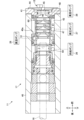
図1は、実施の形態の分解処理装置を一部側断面した説明図である。図1に示すように、分解処理装置10は、水プラズマ発生装置11と、供給部12と、反応管13と、反応炉14とを備えて構成されている。
Figure 1 is an explanatory diagram showing a partial cross-sectional side view of a decomposition treatment device according to an embodiment. As shown in Figure 1, the
水プラズマ発生装置11は、スタンド15を介して所定の高さ位置に支持されている。水プラズマ発生装置11は、前後に延びる陰極16と、陰極16の前端側が挿入されるチャンバ17と、チャンバ17の外側であって斜め下前方に設けられる鉄製円板状の陽極18と、陽極18を支持する陽極支持部19とを備えて構成されている。
The
陰極16は、炭素からなる丸棒によって形成され、送りねじ軸機構21を介して前後方向に変位してチャンバ17への挿入量を調整可能となっている。チャンバ17は、陽極支持部19の上方に支持板22を介して支持されている。陽極支持部19の後端には、前後に延びる延長筒体23が連結され、延長筒体23の後端にはモータ24が設けられている。モータ24の駆動力は、延長筒体23及び陽極支持部19を通じて陽極18に伝達され、陽極18が回転可能に設けられている。
The
チャンバ17の内部には、供給ポンプ26を介して冷却水が供給され、また、高圧ポンプ27を介してプラズマ用水が供給される。プラズマ用水の一部は、チャンバ17の前端側から水プラズマJ(図5参照)として噴射される。チャンバ17に供給された冷却水と、噴射されなかったプラズマ用水とは、真空ポンプ28を介して吸引される。陽極支持部19においても、陽極18の内部を流す冷却水が供給ポンプ26を介して供給され、陽極18にて吸熱を行った冷却水が真空ポンプ28を介して吸引される。チャンバ17の詳細な構成については後述する。
Cooling water is supplied to the inside of the
水プラズマ発生装置11の前方には壁体30が配置され、この壁体30によって水プラズマ発生装置11が設置される空間と、水プラズマJによってガス化した対象物を処理する処理空間31との間での気密性を維持している。処理空間31では、図示省略したが、例えば、シャワー装置により高アルカリ性水を噴射し、ガス化した酸性ガスを中和させている。壁体30には、筒状の反応炉14が貫通して設けられている。
A
次いで、チャンバ17の内部構造について図2ないし図4を参照して説明する。図2は、チャンバの側断面図、図3は、チャンバの平面断面図、図4は、チャンバの縦断面図である。
Next, the internal structure of the
図2及び図3に示すように、水プラズマ発生装置11を構成するチャンバ17は、前後方向に延びる円筒内周面を形成するチャンバ本体40と、チャンバ本体40の前方に装着された前壁部41とを備え、それらの内側に水プラズマJを発生させるための内部空間42を形成している。前壁部41には内部空間42に連通する開口が形成され、この開口を前方から塞ぐように噴射口形成体44が取り付けられている。
As shown in Figures 2 and 3, the
噴射口形成体44には水プラズマJを噴射する噴射口45及び噴射流路46が形成されている。噴射流路46は、中心軸方向が前後方向に向けられて噴射口形成体44を貫通する丸穴状に形成され、前端にて噴射口45を形成している。噴射口45は噴射口形成体44の前面(上下及び左右方向に平行な面)に形成される。言い換えると、噴射口形成体44の前面が噴射口45の形成面とされる。なお、噴射口形成体44及び噴射口45は、前後方向から見て同一中心の円形に形成されている(図6A参照)。
The
チャンバ本体40の内部には、前方寄りの位置に周方向に延びるリブ40aが形成され、このリブ40aより前側にプラズマ用水供給路47が形成されている。また、前壁部41には、その開口内に流れ込むプラズマ用水を排出するプラズマ用水排出路48が形成されている。プラズマ用水供給路47には、高圧ポンプ27から高圧なプラズマ用水が供給され、プラズマ用水排出路48からは真空ポンプ28の負圧によってプラズマ用水が吸引される。プラズマ用水は、冷却用水としても用いられる。更に述べると、プラズマ用水は、水プラズマJの発生に用いられるだけでなく、プラズマ用水供給路47からプラズマ用水排出路48に流れる経路上の噴射口形成体44を含む各構成を冷却している。
Inside the
チャンバ本体40のリブ40aより後側には冷却水供給路50及び冷却水排出路51(図3では不図示)が形成されている。冷却水供給路50には、供給ポンプ26から冷却水が供給され、冷却水排出路51からは真空ポンプ28の負圧によって冷却水が吸引される。プラズマ用水供給路47、冷却水供給路50及び冷却水排出路51は、円筒内周面となる丸穴状に形成されている。
A cooling
図4に示すように、プラズマ用水供給路47は、縦断面視で円形となる内部空間42の下部で連通して左右方向に延出している。具体的には、内部空間42の下部接線方向にプラズマ用水供給路47が延在している。これにより、プラズマ用水供給路47から流れ込むプラズマ用水が内部空間42の周方向に沿って滑らかに流れる。
As shown in FIG. 4, the plasma
水プラズマ発生装置11は、チャンバ17内に収容される概略筒状の渦水流発生器60を備えている。渦水流発生器60は、内部空間42と中心軸C1の位置が一致するように配置されている。なお、この中心軸C1は、上述した噴射口45及び噴射流路46の中心軸とも一致する。よって、噴射口45及び噴射流路46の説明においても、符号C1を付した「中心軸C1」を用いる。縦断面視で内部空間42は、その内周面と渦水流発生器60の外周面との間で円状の空間を形成し、上述のように内部空間42に流れ込んだプラズマ用水は、円状の空間を旋回するように流れる。
The
渦水流発生器60には、内外で連通するように貫通する複数の通路61が形成されている。通路61は、渦水流発生器60の周方向に等角度毎(本実施の形態では120°毎)に形成されている。また、通路61は、前後方向に所定間隔毎に形成されている(図2及び図3参照)。各通路61は、渦水流発生器60の厚さ方向に対して傾斜する方向に延出している。具体的には、各通路61は、連通位置における渦水流発生器60の内周接線方向に延在している。また、通路61の外部から内部にプラズマ用水が流れる方向と、渦水流発生器60の外部でプラズマ用水が旋回して流れる方向とでなす角度θは鋭角となっている。
The
上記のように通路61を形成したので、渦水流発生器60の外部でチャンバ本体40の内周面に沿って流れるプラズマ用水は、通路61を通過して渦水流発生器60の内部に流れ込む。そして、プラズマ用水が渦水流発生器60の内周面に沿って滑らかに流れるようになり、縦断面視で中心軸C1の位置に空洞を形成するように円状に旋回する渦水流が形成される。
By forming the
水プラズマ発生装置11は、チャンバ17内において、渦水流発生器60の後方に更に種々の構成を備えている。かかる構成によって、渦水流発生器60の位置決め、陰極16の冷却、保持及び移動制御、陰極16への電力供給等が実施されるが、ここでは説明を省略する。
The
図5は、水プラズマ発生装置によって水プラズマ噴射した状態を示す説明図である。図5に示すように、チャンバ17の内部にて、上述したように空洞を備えた渦水流が形成された状態で、陰極16及び陽極18に直流電力が供給されると、それらの間にアーク放電ARが発生される。このとき、アーク放電ARは渦水流の空洞の内部を通過するように発生される。このアーク放電ARの発生によって、渦水流を形成するプラズマ用水が解離、電離されて高エネルギーなジェット気流となる水プラズマJが噴射口45から噴射される。
Figure 5 is an explanatory diagram showing the state in which water plasma is sprayed by the water plasma generator. As shown in Figure 5, when a vortex water flow with a cavity is formed inside the
噴射口45から噴射される水プラズマJは極めて高温で超高速な流体となる。水プラズマJの噴射方向は後から前に向かう方向となり、噴射口45及び噴射流路46の中心軸C1方向と平行な前後方向となる。更に述べると、水プラズマJは、噴射口45及び噴射流路46の中心軸C1と同じ中心軸C1を備えた概ね紡錘形や円錐形となって噴射され、噴射口45から離れるに従って次第に広がる形状を備えている。水プラズマJは、中心軸C1が相対的に高温となり、中心軸C1から離れるに従って温度低下する。
The water plasma J injected from the
次に、供給部12の構成について、図5に加え、図6及び図7を参照して説明する。図6Aは、水プラズマ発生装置の一部構成の正面図であり、図6Bは、図6AのB部拡大図である。 図7Aは、供給部の概略斜視図であり、図7Bは、供給部の正面図であり、図7Cは、供給部の縦断面図である。なお、図5は、図6AのA-A線断面図である。
Next, the configuration of the
図6Aに示すように、供給部12は、チャンバ17にて噴射口45を形成する噴射口形成体44に配置されている。具体的には、供給部12は、前後方向(図6Aの紙面直交方向)から見て、噴射口形成体44の前面(図6Aにて手前側の面)における噴射口45の近傍位置に面接触するようねじ部材71及びピン72を介して取り付けられる。
As shown in FIG. 6A, the
よって、供給部12は、噴射口形成体44との接触によって、噴射口形成体44との間で熱伝達可能に設けられる。これにより、噴射口形成体44がチャンバ17内を流れるプラズマ用水(冷却用水)によって冷却されることで、その冷却熱が供給部12に伝達して冷却される。言い換えると、供給部12の熱が噴射口形成体44によって吸熱される。なお、チャンバ17の外側における噴射口45の斜め下前方の近傍に、陽極18の上端が位置するように設けられる。
The
供給部12は、前後方向から見て概略長方形状に形成され、上下方向に対し、長辺及び短辺が約45°傾いた向きに設けられている。供給部12は、配管73を介して送出装置74に接続されており、送出装置74から分解対象物が供給される。供給部12は、水プラズマ発生装置11から噴射される水プラズマJに対し、分解対象物を噴出して供給可能に設けられる。
The
なお、分解対象物は、廃油、PCB、硫酸ピッチ、アスベスト、フロン、ハロン、タイヤ、各種ゴミ等の有害廃棄物としたり、特に有害でない無害のものとすることを例示でき、液状や、粒状や粉状として供給部12を介して供給される。
The materials to be decomposed can be, for example, hazardous waste such as waste oil, PCBs, sulfuric acid pitch, asbestos, fluorocarbons, halon, tires, and various types of garbage, or non-hazardous materials that are not particularly harmful, and are supplied via the
図7A~図7Cに示すように、供給部12は、前後方向に厚みを有する片状またはブロック状に形成された本体76を備えている。また、供給部12は、本体76における図7B中右半部領域に上下に並んで形成されるねじ挿通穴77及びピン挿通穴78を備えている。更に、供給部12は、本体76における図7B中左下コーナー部近傍にてノズル口80を形成するノズル流路81と、下端側にてノズル流路81に連通する供給流路82とを備えている。供給流路82は、配管73を介して送出装置74(図6A参照)に接続される。
As shown in Figures 7A to 7C, the
ねじ挿通穴77には、皿ねじとなるねじ部材71(図6B参照)が挿通され、ピン挿通穴78には、ピン72(図6B参照)が挿通される。
A screw member 71 (see FIG. 6B), which is a flat head screw, is inserted into the
ノズル流路81は、中心軸方向が前後方向に沿う方向に延出する丸穴状に形成され、前端にてノズル口80を形成している。ノズル口80は本体76の前面(上下及び左右方向に平行な面)に形成され、言い換えると、本体76の前面がノズル口80の形成面とされる。ノズル口80の形成面となる本体76の前面と、噴射口45の形成面となる噴射口形成体44の前面とは略平行となっている(図5参照)。ここで、「略平行」は、完全に平行なる状態の他、平行を意図して製造しつつ加工精度や公差、尤度等によって若干角度変化した状態も含む意味である。
The
ノズル口80は、配管73から供給されて供給流路82及びノズル流路81を経た分解対象物を後から前に向かう噴出方向S1(図5及び図7C参照)に沿って噴出する。ここで、ノズル口80から噴出される分解対象物は、軸状またはノズル口80から離れるに従って広がる錘状となる。なお、分解対象物の噴出形態が軸状及び錘状の何れになる場合も、噴出方向S1は、それらの中心軸方向を意味する。
The
図5にて、噴出方向S1の説明にあたり、ノズル口80を通過し、且つ、噴射口45から噴射される水プラズマJの中心軸C1と平行な仮想線L1を設定する。かかる仮想線L1に対する噴出方向S1の傾斜角度αは、0°より大きく45°より小さい範囲内(0°<α<45°)にて設定され、より好ましくは、10°より大きく30°より小さい範囲内(10°<α<30°)にて設定される。
In explaining the ejection direction S1 in FIG. 5, a virtual line L1 is set that passes through the
ノズル流路81の延出方向は、噴出方向S1に応じて設定され、本実施の形態では、本体76の厚さ方向となる前後方向に対して傾斜した方向に設定される。これにより、噴出方向S1をノズル流路81の延出方向と同一方向として前後方向に対して傾斜させることができる。
The extension direction of the
図6A及び図6Bに戻り、前後方向(噴射口45から噴射される水プラズマJの中心軸C1方向)から見て、ノズル口80は、噴射口45の斜め右上方向に位置するよう設けられる。より具体的には、噴射口45の中心軸C1とノズル口80とを通過する仮想線L2が左右方向(水平方向)に対して約45°となるように供給部12が配設されている。かかる仮想線L2にて、噴射口形成体44の外縁を通過する点を通過位置P1とすると、該通過位置P1からノズル口80までの距離に比べ、噴射口45の中心軸C1からノズル口80までの距離の方が短くなっている。よって、仮想線L2上にて、ノズル口80は、噴射口形成体44の外縁の通過位置P1より噴射口45の中心軸C1位置に近い位置に配置される。
6A and 6B, when viewed from the front-rear direction (the direction of the central axis C1 of the water plasma J ejected from the nozzle 45), the
図5に戻り、供給部12にて送出装置74から分解対象物が供給されると、ノズル口80から分解対象物が噴出され、水プラズマJに分解対象物が供給される。供給された分解対象物は、高エネルギーで極めて高温な水プラズマJによって分解処理される。分解対象物が有害廃棄物であれば、該有害廃棄物を無害化した廃棄物に分解することができる。
Returning to FIG. 5, when the object to be decomposed is supplied from the
ここで、噴射口45を形成する噴射口形成体44を含むチャンバ17にあっては、水プラズマJによって加熱されるが、上述のプラズマ用水や冷却用水で冷却され、極めて高温になることが抑制される。供給部12においても、水プラズマJによって加熱されるが、噴射口形成体44と熱伝達されるので、噴射口形成体44と共にプラズマ用水等によって冷却される。これにより、供給部12専用の冷却構造をなくすことができ、構造の簡略化、管理やメンテナンス等の作業負担の軽減を図ることができる。
Here, in the
更に、上述のように供給部12を冷却可能としたので、噴射口45に供給部12を接近させた構成を採用することが可能となる。これにより、水プラズマJにて特に高温となる噴射口45に近い位置にて、供給部12から分解対象物を供給できるので、水プラズマJの高温な領域を有効利用して分解対象物を分解処理する確実性を高めることができる。この結果、水プラズマJによる分解能力を良好に発揮することが可能となる。従って、本実施の形態によれば、トレードオフの関係となる、冷却用構造の簡略化と、水プラズマJによる分解能力の良好な発揮とを同時に実現することができる。
Furthermore, since the
また、供給部12が噴射口形成体44に取り付けられるので、供給部12の支持構造を省略して構造の簡略化を図ることができる。更には、噴射口形成体44に対する供給部12の相対位置を安定して維持でき、水プラズマJの噴射による振動等によって、水プラズマJに対する分解対象物の噴出位置が経時的にずれることを防止することができる。
In addition, since the
また、本実施の形態にて、ノズル口80からの分解対象物の噴出方向S1は、図5に示す傾斜角度αが0°より大きく45°より小さい範囲内となっている。なお、仮に、傾斜角度αを0°以下すなわち噴出方向S1が水プラズマJの中心軸方向と平行ないし斜め上方に設定されると、水プラズマJが噴出する勢いで分解対象物が水プラズマJの内部に入らずに吹き飛ばされ易くなる。
In addition, in this embodiment, the ejection direction S1 of the object to be decomposed from the
一方、仮に傾斜角度αを90°に近い角度にすると、水プラズマJに分解対象物を供給できるものの、水プラズマJの噴射範囲が小さいところに供給されるので、条件によっては水プラズマJによる分解処理が追い付かず分解対象物が下方に突き抜け易くなる。このため、突き抜けた分解対象物が分解されずに堆積されたり、不完全燃焼して煤として堆積する場合がある。 On the other hand, if the inclination angle α is set to an angle close to 90°, the decomposition target can be supplied to the water plasma J, but since the water plasma J is supplied to a small spray range, depending on the conditions, the decomposition process by the water plasma J cannot keep up and the decomposition target is likely to penetrate downward. As a result, the penetrated decomposition target may accumulate without being decomposed, or may be incompletely combusted and accumulate as soot.
本実施の形態のように傾斜角度αを0°より大きく45°より小さい範囲内とすると、水プラズマJの噴射範囲にて分解対象物が通過する長さを長くしつつ、分解対象物が水プラズマJにより吹き飛ばされないよう内部に供給可能となる。これにより、煤の堆積等を回避できるようにしつつ、高エネルギーな水プラズマJによって分解対象物を効率良く分解処理することができる。 When the inclination angle α is set within the range of greater than 0° and less than 45° as in this embodiment, the length through which the decomposition object passes within the spray range of the water plasma J is increased, while the decomposition object can be supplied to the inside without being blown away by the water plasma J. This makes it possible to efficiently decompose the decomposition object using the high-energy water plasma J while avoiding the accumulation of soot, etc.
また、水プラズマJの噴射口45と分解対象物のノズル口80は、両方とも上下及び左右方向に平行となる面に形成されている。これにより、分解対象物の噴出方向S1の傾斜角度αを上述した範囲に設定でき、噴出された分解を水プラズマJの中心軸C1に徐々に近付けつつ、水プラズマJにおける噴射口45に近い高温な領域に分解対象物を供給可能となる。
In addition, the
図6Aに示す仮想線L2上にて、ノズル口80は、噴射口形成体44の外縁の通過位置P1より噴射口45の中心軸C1位置の方が近くなるよう配置され、噴射口45に対しノズル口80を近付けることができる。このようにノズル口80が噴射口45に近付くことによっても、水プラズマJにおける噴射口45に近い高温な領域に分解対象物を供給可能となる。
On the imaginary line L2 shown in FIG. 6A, the
続いて、図1に示した反応管13及び反応炉14について説明する。
Next, we will explain the
反応管13は、反応炉14の内部にて所定の支持構造(図示省略)を介して支持され、水プラズマJの噴射方向となる前後方向に延びる筒状体100によって形成される。筒状体100は、水プラズマ発生装置11の前方に隣り合う位置に設けられる第1管部材101と、第1管部材101の前端側に設けられる第2管部材102とを備えている。各管部材101、102は、例えば配管用炭素鋼鋼管等が用いられ、厚さが単一の層構造で形成される金属製の円筒部材とされる。
The
図8Aは、反応管の拡大断面図であり、図8Bは、反応管の斜視図である。図8A及び図8Bに示すように、第1管部材101は、その後端位置にて、水プラズマJが後から前へ流れる断面領域より大きい開口サイズ(径寸法)となるよう形成されている。これにより、第1管部材101の後端側(一端側)にて、水プラズマJと共に第1管部材101の内部に空気を導入する導入口103を形成している。円形に形成される導入口103における内周の直径寸法は、110mmより大きく200mmより小さい範囲内で設定することが例示できる。
Figure 8A is an enlarged cross-sectional view of the reaction tube, and Figure 8B is a perspective view of the reaction tube. As shown in Figures 8A and 8B, the
第2管部材102は、第1管部材101より大きい開口サイズ(径寸法)に形成され、後端側(一端側)にて、第1管部材101の前端側(他端側)を所定の前後幅に亘って受容している。第2管部材102は、第1管部材101と同一の中心軸線上に設けられる。よって、第2管部材102の後端側内面と、第1管部材101の前端側外面との間には、中心軸回りの周方向にて360°全域に空間が形成され、該空間が流路105として形成される。流路105は、筒状体100の外部空間と内部空間とを連通している。
The
第1管部材101の前端側と第2管部材102の後端側との間には、それらの径方向に延びる複数の支持軸107が架け渡されて設けられる。これにより、複数の支持軸107を介し、第1管部材101と第2管部材102とが連結され、且つ、それらの径方向における流路105の幅が維持される。支持軸107は、ボルトやねじ部材等によって構成される。支持軸107は、各管部材101、102の中心軸回りの周方向にて、90°間隔毎に設けられる。
A number of
図1に戻り、反応炉14は、水プラズマ発生装置11の前方に配置され、反応管13を囲う位置に設けられる。反応炉14は、壁体30を貫通して設けられる。壁体30における反応炉14の貫通部分は全溶接され、壁体30によって反応炉14が保持されるとともに、それらの間での気密性が保たれる。
Returning to FIG. 1, the
反応炉14は、冷却容器110と、冷却容器110の後方に設けられて段付き円筒形状をなす後方形成部111と、冷却容器110の内周に沿って設けられる耐熱層112とを備えている。後方形成部111の内側に、反応管13の後方領域が受容される。耐熱層112は、例えば、耐火煉瓦によって構成される。
The
冷却容器110は、円筒状に形成される筒本体部115と、筒本体部115の前端側(水プラズマ発生装置11と反対側)に形成される前方開口形成部116とを備えている。筒本体部115の軸線方向は、水プラズマ発生装置11から離れるに従って低くなるように傾斜している。
The cooling
冷却容器110の形成壁を構成する筒本体部115及び前方開口形成部116は、二重構造となっており、その厚み内に冷却水が流れる単一の空間117を形成している。この空間117には、冷却水用の供給路118と排出路119とが連通している。供給路118は、前方開口形成部116の下端側に設けられ、排出路119は、筒本体部115の後方上端側に形成されている。
The
冷却容器110では、図示しないポンプを介して供給路118から冷却水が供給され、空間117内に導入される。そして、空間117において供給路118から排出路119に流れる冷却水によって、水プラズマJによって発生した熱が吸収され、冷却容器110の冷却作用が得られる。
In the
上述のように水プラズマ発生装置11のチャンバ17から水プラズマJを噴射すると、図8Aに示すように、導入口103から反応管13の内部に水プラズマJを導入した状態にすることができる。この状態では、水プラズマJの噴射直後において噴射領域の周辺に熱が拡散することを反応管13により抑制でき、水プラズマJの噴射領域を反応管13で覆うようにして高温状態に維持することができる。これにより、水プラズマJによる分解対象物の分解処理を、高温状態となる反応管13の内部で確実且つ効率良く実施可能となる。
When water plasma J is sprayed from
しかも、水プラズマJによる分解処理においては、導入口103から第1管部材101の内部に向かって水プラズマJと共に空気(酸素)を導入することができる。これにより、分解処理での不完全燃焼を抑制することができ、煤の発生を減少させることができる。
Moreover, in the decomposition process using water plasma J, air (oxygen) can be introduced from the
更に、第1管部材101と第2管部材102との間に流路105を形成したので、水プラズマJの噴射位置近傍となる導入口103だけでなく、水プラズマJの噴射方向中間部においても筒状体100の外部から空気を導入することができる。これにより、分解処理での不完全燃焼や、煤の発生をより一層良好に抑制することができる。しかも、流路105での空気の流れによって、第1管部材101と第2管部材102の連結部分やその周辺を冷却することもできる。
Furthermore, since a
また、第1管部材101より第2管部材102の方が開口サイズを大きくなるので、噴射口45から次第に広がって噴射される水プラズマJの形態に応じて筒状体100を形成することができる。
In addition, since the opening size of the
各管部材101、102は、径寸法が小さ過ぎると熱が籠りすぎて水プラズマJと分解対象物との反応熱の影響を受け易くなり、径寸法が大き過ぎると内部の熱が外部に逃げてしまって高温維持効果が減少する。よって、各管部材101、102の径寸法は、水プラズマJの能力等の各種条件に応じて適正に設定する必要があり、これを考慮し、上記のように導入口103における内周の直径寸法を110mmより大きく200mmより小さい範囲内で設定するとよい。
If the diameter of each
分解対象物の分解処理中において、反応炉14の厚み内に冷却水を通過させることで冷却して利用することができる。反応炉14における冷却容器110の内周に沿って耐熱層112が設けられるので、気化した分解対象物が反応炉14の内周面付近で急速に冷却され、該内周面に液状となって付着して汚れることを防止することができる。
During the decomposition process of the decomposition target, cooling water can be passed through the thickness of the
なお、本発明は上記実施の形態に限定されず、種々変更して実施することが可能である。上記実施の形態において、添付図面に図示されている大きさや形状、方向などについては、これに限定されず、本発明の効果を発揮する範囲内で適宜変更することが可能である。その他、本発明の目的の範囲を逸脱しない限りにおいて適宜変更して実施することが可能である。 The present invention is not limited to the above embodiment, and can be modified in various ways. In the above embodiment, the size, shape, direction, etc. shown in the attached drawings are not limited to these, and can be modified as appropriate within the scope of the effects of the present invention. In addition, the present invention can be modified as appropriate without departing from the scope of the purpose of the present invention.
例えば、上記実施の形態では、供給部12において、ノズル口80及びノズル流路81をそれぞれ単一としたが、これに限られるものでなく、図9に示すように変更してもよい。図9Aは、変形例に係る供給部の概略斜視図であり、図9Bは、変形例に係る供給部の正面図であり、図9Cは、変形例に係る供給部の縦断面図である。図9A~図9Cの変形例では、供給部12がノズル口86及びノズル流路87を複数(図示では5つ)備えている。変形例の構成によれば、ノズル口86が複数となることで、分解対象物の供給量を略同一に維持しつつ、表面積に対する体積比率を小さくでき、水プラズマJからの熱吸収量を増やして温度上昇し易くすることができる。
For example, in the above embodiment, the
なお、図9A~図9Cの変形例は、同図中上下方向延出する長孔状にねじ挿通穴88が形成され、ねじ挿通穴88の上方にピン挿通穴89が形成される。
In the modified example shown in Figures 9A to 9C, a
更に、前方から見た噴射口形成体44への供給部12の配設位置は、ノズル口80から分解対象物を水プラズマJに噴出できる限りにおいて、種々の変更が可能である。例えば、噴射口45よりノズル口80を下方に配設してもよく、図6Aの仮想線L2の角度を左右方向に対して45°以外の任意の角度(例えば、90°や60°等)としてもよい。但し、噴射口45から真上方向に向かう位置には、水プラズマJを発生させる準備段階で、アーク放電ARを発生させるためのアルミ棒を設置する場合があるので、該アルミ棒を避けるように供給部12を配設するとよい。また、噴射口45を挟む両側に供給部12を設ける場合には、両側の供給部12それぞれの左右方向に対する角度を同一としてもよいし、相違させてもよい。
Furthermore, the position of the
また、上記実施の形態では、噴射口形成体44に供給部12を取り付ける構成としたが、噴射口形成体44に供給部12を一体的に連なるよう形成してもよい。更には、噴射口形成体44と供給部12との間で熱伝達可能であれば、それらの間にスペーサ等の構造物が介在してもよい。
In addition, in the above embodiment, the
また、水プラズマ発生装置11は、廃棄物処理に利用することに限定されるものでなく、溶射等の水プラズマを利用した任意の処理に利用することができる。
Furthermore, the
本発明は、水プラズマ発生装置から噴射された水プラズマによる分解能力を良好に発揮でき、且つ、冷却用の構造を簡略化できる、という効果を得る。 The present invention has the advantage that it can effectively utilize the decomposition power of the water plasma sprayed from the water plasma generator, and can simplify the cooling structure.
10 :分解処理装置
11 :水プラズマ発生装置
12 :供給部
13 :反応管
14 :反応炉
16 :陰極
17 :チャンバ
18 :陽極
44 :噴射口形成体
45 :噴射口
80 :ノズル口
100 :筒状体
101 :管部材
101 :第1管部材
102 :第2管部材
102 :管部材
103 :導入口
105 :流路
107 :支持軸
110 :冷却容器
112 :耐熱層
AR :アーク放電
J :水プラズマ
Reference Signs List 10: Decomposition treatment device 11: Water plasma generator 12: Supply section 13: Reaction tube 14: Reaction furnace 16: Cathode 17: Chamber 18: Anode 44: Jet nozzle forming body 45: Jet nozzle 80: Nozzle nozzle 100: Cylindrical body 101: Tube member 101: First tube member 102: Second tube member 102: Tube member 103: Inlet 105: Flow path 107: Support shaft 110: Cooling vessel 112: Heat-resistant layer AR: Arc discharge J: Water plasma
Claims (6)
前記水プラズマに分解対象物を供給する供給部とを備え、前記水プラズマによって前記分解対象物を分解処理する分解処理装置であって、
前記水プラズマ発生装置は、内部に供給される水によって前記渦水流を形成して噴射口から前記水プラズマを噴射するするチャンバと、前記チャンバ内の前記渦水流を通過するアーク放電を発生させる陽極及び陰極とを備え、前記陽極は前記チャンバの外側における前記噴射口の近傍位置に設けられ、
前記チャンバは、前記噴射口を形成し、該チャンバの内部に供給される水によって冷却される噴射口形成体を備え、
前記供給部は、前記噴射口形成体に配置され、前記噴射口形成体との熱伝達によって冷却されることを特徴とする分解処理装置。 a water plasma generator that injects water plasma by passing an arc discharge through the inside of a vortex water flow;
a supply unit that supplies a decomposition target to the water plasma, and the decomposition treatment device decomposes the decomposition target by the water plasma,
The water plasma generator includes a chamber for forming the vortex water flow by water supplied therein and for spraying the water plasma from a nozzle, and an anode and a cathode for generating an arc discharge passing through the vortex water flow in the chamber, the anode being provided at a position near the nozzle outside the chamber,
the chamber includes a jet nozzle forming body that forms the jet nozzle and is cooled by water supplied to the inside of the chamber;
The decomposition processing apparatus is characterized in that the supply section is disposed on the injection port formation body and is cooled by heat transfer between the supply section and the injection port formation body.
前記供給部における前記ノズル口の形成面と、前記噴射口形成体における前記噴射口の形成面とは略平行とされることを特徴とする請求項1に記載の分解処理装置。 The supply unit includes a nozzle port for ejecting the decomposition target,
2. The decomposition processing apparatus according to claim 1, wherein a surface of the nozzle port in the supply section and a surface of the jet port in the jet port forming body are substantially parallel to each other.
前記ノズル口からの前記分解対象物の噴出方向の角度は、該ノズル口を通過して前記水プラズマの中心軸と平行な仮想線に対し、0°より大きく45°より小さい範囲内に設定されることを特徴とする請求項1に記載の分解処理装置。 The supply unit includes a nozzle port for ejecting the decomposition target,
2. The decomposition treatment device according to claim 1, wherein an angle of the ejection direction of the material to be decomposed from the nozzle opening is set within a range of greater than 0° and less than 45° with respect to an imaginary line passing through the nozzle opening and parallel to a central axis of the water plasma.
Priority Applications (2)
| Application Number | Priority Date | Filing Date | Title |
|---|---|---|---|
| JP2023190479A JP7583473B1 (en) | 2023-11-08 | 2023-11-08 | Decomposition treatment equipment |
| PCT/JP2024/039601 WO2025100481A1 (en) | 2023-11-08 | 2024-11-07 | Decomposition treatment device |
Applications Claiming Priority (1)
| Application Number | Priority Date | Filing Date | Title |
|---|---|---|---|
| JP2023190479A JP7583473B1 (en) | 2023-11-08 | 2023-11-08 | Decomposition treatment equipment |
Publications (2)
| Publication Number | Publication Date |
|---|---|
| JP7583473B1 true JP7583473B1 (en) | 2024-11-14 |
| JP2025078131A JP2025078131A (en) | 2025-05-20 |
Family
ID=93429274
Family Applications (1)
| Application Number | Title | Priority Date | Filing Date |
|---|---|---|---|
| JP2023190479A Active JP7583473B1 (en) | 2023-11-08 | 2023-11-08 | Decomposition treatment equipment |
Country Status (2)
| Country | Link |
|---|---|
| JP (1) | JP7583473B1 (en) |
| WO (1) | WO2025100481A1 (en) |
Citations (4)
| Publication number | Priority date | Publication date | Assignee | Title |
|---|---|---|---|---|
| JP2021118113A (en) | 2020-01-27 | 2021-08-10 | 株式会社Helix | Jig for water plasma generator and positioning method used for it |
| JP2021115535A (en) | 2020-01-27 | 2021-08-10 | 株式会社Helix | Decomposition processing equipment and cooling equipment used for this |
| JP2021157931A (en) | 2020-03-26 | 2021-10-07 | 株式会社Helix | Water plasma generator and cathode holding unit used for it |
| JP2023017815A (en) | 2018-11-08 | 2023-02-07 | 株式会社Helix | decomposition treatment equipment |
Family Cites Families (2)
| Publication number | Priority date | Publication date | Assignee | Title |
|---|---|---|---|---|
| JPH08236293A (en) * | 1994-10-26 | 1996-09-13 | Matsushita Electric Ind Co Ltd | Microwave plasma torch and plasma generation method |
| JPH09262460A (en) * | 1996-03-27 | 1997-10-07 | Chichibu Onoda Cement Corp | Treatment of organic compound and device therefor |
-
2023
- 2023-11-08 JP JP2023190479A patent/JP7583473B1/en active Active
-
2024
- 2024-11-07 WO PCT/JP2024/039601 patent/WO2025100481A1/en active Pending
Patent Citations (4)
| Publication number | Priority date | Publication date | Assignee | Title |
|---|---|---|---|---|
| JP2023017815A (en) | 2018-11-08 | 2023-02-07 | 株式会社Helix | decomposition treatment equipment |
| JP2021118113A (en) | 2020-01-27 | 2021-08-10 | 株式会社Helix | Jig for water plasma generator and positioning method used for it |
| JP2021115535A (en) | 2020-01-27 | 2021-08-10 | 株式会社Helix | Decomposition processing equipment and cooling equipment used for this |
| JP2021157931A (en) | 2020-03-26 | 2021-10-07 | 株式会社Helix | Water plasma generator and cathode holding unit used for it |
Also Published As
| Publication number | Publication date |
|---|---|
| WO2025100481A1 (en) | 2025-05-15 |
| JP2025078131A (en) | 2025-05-20 |
Similar Documents
| Publication | Publication Date | Title |
|---|---|---|
| JP7420197B2 (en) | Decomposition processing equipment | |
| US12011629B2 (en) | Decomposition processor and decomposition processor mounted vehicle | |
| JP7677676B2 (en) | Decomposition treatment device and cooling device used therein | |
| JP6035438B1 (en) | Eddy water flow generator, water plasma generator, decomposition treatment apparatus, vehicle equipped with the decomposition treatment apparatus, and decomposition treatment method | |
| JP7583473B1 (en) | Decomposition treatment equipment | |
| JP7606248B1 (en) | Decomposition treatment equipment | |
| JP7606249B1 (en) | Decomposition treatment equipment | |
| JP6629705B2 (en) | Decomposition processing apparatus, vehicle equipped with decomposition processing apparatus, and decomposition processing method | |
| JP2010106132A (en) | Solid fuel gasification burner and gasification furnace equipped with the same | |
| JP2021157931A (en) | Water plasma generator and cathode holding unit used for it | |
| JP2025176362A (en) | heating device | |
| JP6820598B2 (en) | Vehicle with thermal spraying device | |
| JP2021118113A (en) | Jig for water plasma generator and positioning method used for it | |
| JP2017123323A (en) | Swirl generator | |
| WO2025243984A1 (en) | Supply device and heating device | |
| JP2023181940A (en) | waste treatment equipment | |
| CN116428598A (en) | Exhaust gas combustion device | |
| JP2021118112A (en) | Water plasma generator, energizing member used for it, water plasma generation method |
Legal Events
| Date | Code | Title | Description |
|---|---|---|---|
| A621 | Written request for application examination |
Free format text: JAPANESE INTERMEDIATE CODE: A621 Effective date: 20231108 |
|
| TRDD | Decision of grant or rejection written | ||
| A01 | Written decision to grant a patent or to grant a registration (utility model) |
Free format text: JAPANESE INTERMEDIATE CODE: A01 Effective date: 20241022 |
|
| A61 | First payment of annual fees (during grant procedure) |
Free format text: JAPANESE INTERMEDIATE CODE: A61 Effective date: 20241025 |
|
| R150 | Certificate of patent or registration of utility model |
Ref document number: 7583473 Country of ref document: JP Free format text: JAPANESE INTERMEDIATE CODE: R150 |