JP7584513B2 - Apparatus and method for laser-based single-cell recovery from microcapillary arrays - Google Patents
Apparatus and method for laser-based single-cell recovery from microcapillary arrays Download PDFInfo
- Publication number
- JP7584513B2 JP7584513B2 JP2022525999A JP2022525999A JP7584513B2 JP 7584513 B2 JP7584513 B2 JP 7584513B2 JP 2022525999 A JP2022525999 A JP 2022525999A JP 2022525999 A JP2022525999 A JP 2022525999A JP 7584513 B2 JP7584513 B2 JP 7584513B2
- Authority
- JP
- Japan
- Prior art keywords
- microcapillary
- laser
- well
- contents
- cells
- Prior art date
- Legal status (The legal status is an assumption and is not a legal conclusion. Google has not performed a legal analysis and makes no representation as to the accuracy of the status listed.)
- Active
Links
Images





Classifications
-
- B—PERFORMING OPERATIONS; TRANSPORTING
- B01—PHYSICAL OR CHEMICAL PROCESSES OR APPARATUS IN GENERAL
- B01L—CHEMICAL OR PHYSICAL LABORATORY APPARATUS FOR GENERAL USE
- B01L3/00—Containers or dishes for laboratory use, e.g. laboratory glassware; Droppers
- B01L3/02—Burettes; Pipettes
- B01L3/0241—Drop counters; Drop formers
- B01L3/0268—Drop counters; Drop formers using pulse dispensing or spraying, eg. inkjet type, piezo actuated ejection of droplets from capillaries
-
- B—PERFORMING OPERATIONS; TRANSPORTING
- B01—PHYSICAL OR CHEMICAL PROCESSES OR APPARATUS IN GENERAL
- B01L—CHEMICAL OR PHYSICAL LABORATORY APPARATUS FOR GENERAL USE
- B01L3/00—Containers or dishes for laboratory use, e.g. laboratory glassware; Droppers
- B01L3/50—Containers for the purpose of retaining a material to be analysed, e.g. test tubes
- B01L3/508—Rigid containers without fluid transport within
- B01L3/5085—Rigid containers without fluid transport within for multiple samples, e.g. microtitration plates
- B01L3/50857—Rigid containers without fluid transport within for multiple samples, e.g. microtitration plates using arrays or bundles of open capillaries for holding samples
-
- B—PERFORMING OPERATIONS; TRANSPORTING
- B01—PHYSICAL OR CHEMICAL PROCESSES OR APPARATUS IN GENERAL
- B01L—CHEMICAL OR PHYSICAL LABORATORY APPARATUS FOR GENERAL USE
- B01L7/00—Heating or cooling apparatus; Heat insulating devices
- B01L7/52—Heating or cooling apparatus; Heat insulating devices with provision for submitting samples to a predetermined sequence of different temperatures, e.g. for treating nucleic acid samples
-
- C—CHEMISTRY; METALLURGY
- C12—BIOCHEMISTRY; BEER; SPIRITS; WINE; VINEGAR; MICROBIOLOGY; ENZYMOLOGY; MUTATION OR GENETIC ENGINEERING
- C12N—MICROORGANISMS OR ENZYMES; COMPOSITIONS THEREOF; PROPAGATING, PRESERVING, OR MAINTAINING MICROORGANISMS; MUTATION OR GENETIC ENGINEERING; CULTURE MEDIA
- C12N15/00—Mutation or genetic engineering; DNA or RNA concerning genetic engineering, vectors, e.g. plasmids, or their isolation, preparation or purification; Use of hosts therefor
- C12N15/09—Recombinant DNA-technology
- C12N15/10—Processes for the isolation, preparation or purification of DNA or RNA
- C12N15/1034—Isolating an individual clone by screening libraries
- C12N15/1065—Preparation or screening of tagged libraries, e.g. tagged microorganisms by STM-mutagenesis, tagged polynucleotides, gene tags
-
- C—CHEMISTRY; METALLURGY
- C12—BIOCHEMISTRY; BEER; SPIRITS; WINE; VINEGAR; MICROBIOLOGY; ENZYMOLOGY; MUTATION OR GENETIC ENGINEERING
- C12N—MICROORGANISMS OR ENZYMES; COMPOSITIONS THEREOF; PROPAGATING, PRESERVING, OR MAINTAINING MICROORGANISMS; MUTATION OR GENETIC ENGINEERING; CULTURE MEDIA
- C12N15/00—Mutation or genetic engineering; DNA or RNA concerning genetic engineering, vectors, e.g. plasmids, or their isolation, preparation or purification; Use of hosts therefor
- C12N15/09—Recombinant DNA-technology
- C12N15/10—Processes for the isolation, preparation or purification of DNA or RNA
- C12N15/1096—Processes for the isolation, preparation or purification of DNA or RNA cDNA Synthesis; Subtracted cDNA library construction, e.g. RT, RT-PCR
-
- C—CHEMISTRY; METALLURGY
- C12—BIOCHEMISTRY; BEER; SPIRITS; WINE; VINEGAR; MICROBIOLOGY; ENZYMOLOGY; MUTATION OR GENETIC ENGINEERING
- C12Q—MEASURING OR TESTING PROCESSES INVOLVING ENZYMES, NUCLEIC ACIDS OR MICROORGANISMS; COMPOSITIONS OR TEST PAPERS THEREFOR; PROCESSES OF PREPARING SUCH COMPOSITIONS; CONDITION-RESPONSIVE CONTROL IN MICROBIOLOGICAL OR ENZYMOLOGICAL PROCESSES
- C12Q1/00—Measuring or testing processes involving enzymes, nucleic acids or microorganisms; Compositions therefor; Processes of preparing such compositions
- C12Q1/02—Measuring or testing processes involving enzymes, nucleic acids or microorganisms; Compositions therefor; Processes of preparing such compositions involving viable microorganisms
- C12Q1/24—Methods of sampling, or inoculating or spreading a sample; Methods of physically isolating an intact microorganisms
-
- C—CHEMISTRY; METALLURGY
- C12—BIOCHEMISTRY; BEER; SPIRITS; WINE; VINEGAR; MICROBIOLOGY; ENZYMOLOGY; MUTATION OR GENETIC ENGINEERING
- C12Q—MEASURING OR TESTING PROCESSES INVOLVING ENZYMES, NUCLEIC ACIDS OR MICROORGANISMS; COMPOSITIONS OR TEST PAPERS THEREFOR; PROCESSES OF PREPARING SUCH COMPOSITIONS; CONDITION-RESPONSIVE CONTROL IN MICROBIOLOGICAL OR ENZYMOLOGICAL PROCESSES
- C12Q1/00—Measuring or testing processes involving enzymes, nucleic acids or microorganisms; Compositions therefor; Processes of preparing such compositions
- C12Q1/68—Measuring or testing processes involving enzymes, nucleic acids or microorganisms; Compositions therefor; Processes of preparing such compositions involving nucleic acids
- C12Q1/6806—Preparing nucleic acids for analysis, e.g. for polymerase chain reaction [PCR] assay
-
- C—CHEMISTRY; METALLURGY
- C12—BIOCHEMISTRY; BEER; SPIRITS; WINE; VINEGAR; MICROBIOLOGY; ENZYMOLOGY; MUTATION OR GENETIC ENGINEERING
- C12Q—MEASURING OR TESTING PROCESSES INVOLVING ENZYMES, NUCLEIC ACIDS OR MICROORGANISMS; COMPOSITIONS OR TEST PAPERS THEREFOR; PROCESSES OF PREPARING SUCH COMPOSITIONS; CONDITION-RESPONSIVE CONTROL IN MICROBIOLOGICAL OR ENZYMOLOGICAL PROCESSES
- C12Q1/00—Measuring or testing processes involving enzymes, nucleic acids or microorganisms; Compositions therefor; Processes of preparing such compositions
- C12Q1/68—Measuring or testing processes involving enzymes, nucleic acids or microorganisms; Compositions therefor; Processes of preparing such compositions involving nucleic acids
- C12Q1/6869—Methods for sequencing
-
- G—PHYSICS
- G01—MEASURING; TESTING
- G01N—INVESTIGATING OR ANALYSING MATERIALS BY DETERMINING THEIR CHEMICAL OR PHYSICAL PROPERTIES
- G01N1/00—Sampling; Preparing specimens for investigation
- G01N1/02—Devices for withdrawing samples
- G01N1/04—Devices for withdrawing samples in the solid state, e.g. by cutting
-
- G—PHYSICS
- G01—MEASURING; TESTING
- G01N—INVESTIGATING OR ANALYSING MATERIALS BY DETERMINING THEIR CHEMICAL OR PHYSICAL PROPERTIES
- G01N1/00—Sampling; Preparing specimens for investigation
- G01N1/28—Preparing specimens for investigation including physical details of (bio-)chemical methods covered elsewhere, e.g. G01N33/50, C12Q
- G01N1/30—Staining; Impregnating ; Fixation; Dehydration; Multistep processes for preparing samples of tissue, cell or nucleic acid material and the like for analysis
- G01N1/31—Apparatus therefor
- G01N1/312—Apparatus therefor for samples mounted on planar substrates
-
- G—PHYSICS
- G01—MEASURING; TESTING
- G01N—INVESTIGATING OR ANALYSING MATERIALS BY DETERMINING THEIR CHEMICAL OR PHYSICAL PROPERTIES
- G01N1/00—Sampling; Preparing specimens for investigation
- G01N1/28—Preparing specimens for investigation including physical details of (bio-)chemical methods covered elsewhere, e.g. G01N33/50, C12Q
- G01N1/42—Low-temperature sample treatment, e.g. cryofixation
-
- G—PHYSICS
- G01—MEASURING; TESTING
- G01N—INVESTIGATING OR ANALYSING MATERIALS BY DETERMINING THEIR CHEMICAL OR PHYSICAL PROPERTIES
- G01N1/00—Sampling; Preparing specimens for investigation
- G01N1/28—Preparing specimens for investigation including physical details of (bio-)chemical methods covered elsewhere, e.g. G01N33/50, C12Q
- G01N1/44—Sample treatment involving radiation, e.g. heat
-
- G—PHYSICS
- G01—MEASURING; TESTING
- G01N—INVESTIGATING OR ANALYSING MATERIALS BY DETERMINING THEIR CHEMICAL OR PHYSICAL PROPERTIES
- G01N21/00—Investigating or analysing materials by the use of optical means, i.e. using sub-millimetre waves, infrared, visible or ultraviolet light
- G01N21/62—Systems in which the material investigated is excited whereby it emits light or causes a change in wavelength of the incident light
- G01N21/63—Systems in which the material investigated is excited whereby it emits light or causes a change in wavelength of the incident light optically excited
-
- G—PHYSICS
- G01—MEASURING; TESTING
- G01N—INVESTIGATING OR ANALYSING MATERIALS BY DETERMINING THEIR CHEMICAL OR PHYSICAL PROPERTIES
- G01N33/00—Investigating or analysing materials by specific methods not covered by groups G01N1/00 - G01N31/00
- G01N33/48—Biological material, e.g. blood, urine; Haemocytometers
- G01N33/50—Chemical analysis of biological material, e.g. blood, urine; Testing involving biospecific ligand binding methods; Immunological testing
- G01N33/5005—Chemical analysis of biological material, e.g. blood, urine; Testing involving biospecific ligand binding methods; Immunological testing involving human or animal cells
- G01N33/5008—Chemical analysis of biological material, e.g. blood, urine; Testing involving biospecific ligand binding methods; Immunological testing involving human or animal cells for testing or evaluating the effect of chemical or biological compounds, e.g. drugs, cosmetics
- G01N33/5044—Chemical analysis of biological material, e.g. blood, urine; Testing involving biospecific ligand binding methods; Immunological testing involving human or animal cells for testing or evaluating the effect of chemical or biological compounds, e.g. drugs, cosmetics involving specific cell types
- G01N33/5047—Cells of the immune system
- G01N33/5052—Cells of the immune system involving B-cells
-
- G—PHYSICS
- G02—OPTICS
- G02B—OPTICAL ELEMENTS, SYSTEMS OR APPARATUS
- G02B26/00—Optical devices or arrangements for the control of light using movable or deformable optical elements
- G02B26/08—Optical devices or arrangements for the control of light using movable or deformable optical elements for controlling the direction of light
- G02B26/10—Scanning systems
- G02B26/105—Scanning systems with one or more pivoting mirrors or galvano-mirrors
-
- G—PHYSICS
- G02—OPTICS
- G02B—OPTICAL ELEMENTS, SYSTEMS OR APPARATUS
- G02B27/00—Optical systems or apparatus not provided for by any of the groups G02B1/00 - G02B26/00, G02B30/00
- G02B27/09—Beam shaping, e.g. changing the cross-sectional area, not otherwise provided for
- G02B27/0938—Using specific optical elements
- G02B27/0977—Reflective elements
-
- H—ELECTRICITY
- H01—ELECTRIC ELEMENTS
- H01S—DEVICES USING THE PROCESS OF LIGHT AMPLIFICATION BY STIMULATED EMISSION OF RADIATION [LASER] TO AMPLIFY OR GENERATE LIGHT; DEVICES USING STIMULATED EMISSION OF ELECTROMAGNETIC RADIATION IN WAVE RANGES OTHER THAN OPTICAL
- H01S3/00—Lasers, i.e. devices using stimulated emission of electromagnetic radiation in the infrared, visible or ultraviolet wave range
- H01S3/10—Controlling the intensity, frequency, phase, polarisation or direction of the emitted radiation, e.g. switching, gating, modulating or demodulating
- H01S3/10038—Amplitude control
- H01S3/10046—Pulse repetition rate control
-
- B—PERFORMING OPERATIONS; TRANSPORTING
- B01—PHYSICAL OR CHEMICAL PROCESSES OR APPARATUS IN GENERAL
- B01L—CHEMICAL OR PHYSICAL LABORATORY APPARATUS FOR GENERAL USE
- B01L2300/00—Additional constructional details
- B01L2300/08—Geometry, shape and general structure
- B01L2300/0809—Geometry, shape and general structure rectangular shaped
- B01L2300/0822—Slides
-
- B—PERFORMING OPERATIONS; TRANSPORTING
- B01—PHYSICAL OR CHEMICAL PROCESSES OR APPARATUS IN GENERAL
- B01L—CHEMICAL OR PHYSICAL LABORATORY APPARATUS FOR GENERAL USE
- B01L2300/00—Additional constructional details
- B01L2300/08—Geometry, shape and general structure
- B01L2300/0832—Geometry, shape and general structure cylindrical, tube shaped
- B01L2300/0838—Capillaries
-
- B—PERFORMING OPERATIONS; TRANSPORTING
- B01—PHYSICAL OR CHEMICAL PROCESSES OR APPARATUS IN GENERAL
- B01L—CHEMICAL OR PHYSICAL LABORATORY APPARATUS FOR GENERAL USE
- B01L2300/00—Additional constructional details
- B01L2300/08—Geometry, shape and general structure
- B01L2300/0893—Geometry, shape and general structure having a very large number of wells, microfabricated wells
-
- B—PERFORMING OPERATIONS; TRANSPORTING
- B01—PHYSICAL OR CHEMICAL PROCESSES OR APPARATUS IN GENERAL
- B01L—CHEMICAL OR PHYSICAL LABORATORY APPARATUS FOR GENERAL USE
- B01L2400/00—Moving or stopping fluids
- B01L2400/04—Moving fluids with specific forces or mechanical means
- B01L2400/0403—Moving fluids with specific forces or mechanical means specific forces
- B01L2400/0442—Moving fluids with specific forces or mechanical means specific forces thermal energy, e.g. vaporisation, bubble jet
-
- C—CHEMISTRY; METALLURGY
- C12—BIOCHEMISTRY; BEER; SPIRITS; WINE; VINEGAR; MICROBIOLOGY; ENZYMOLOGY; MUTATION OR GENETIC ENGINEERING
- C12Q—MEASURING OR TESTING PROCESSES INVOLVING ENZYMES, NUCLEIC ACIDS OR MICROORGANISMS; COMPOSITIONS OR TEST PAPERS THEREFOR; PROCESSES OF PREPARING SUCH COMPOSITIONS; CONDITION-RESPONSIVE CONTROL IN MICROBIOLOGICAL OR ENZYMOLOGICAL PROCESSES
- C12Q2521/00—Reaction characterised by the enzymatic activity
- C12Q2521/10—Nucleotidyl transfering
- C12Q2521/107—RNA dependent DNA polymerase,(i.e. reverse transcriptase)
-
- C—CHEMISTRY; METALLURGY
- C12—BIOCHEMISTRY; BEER; SPIRITS; WINE; VINEGAR; MICROBIOLOGY; ENZYMOLOGY; MUTATION OR GENETIC ENGINEERING
- C12Q—MEASURING OR TESTING PROCESSES INVOLVING ENZYMES, NUCLEIC ACIDS OR MICROORGANISMS; COMPOSITIONS OR TEST PAPERS THEREFOR; PROCESSES OF PREPARING SUCH COMPOSITIONS; CONDITION-RESPONSIVE CONTROL IN MICROBIOLOGICAL OR ENZYMOLOGICAL PROCESSES
- C12Q2563/00—Nucleic acid detection characterized by the use of physical, structural and functional properties
- C12Q2563/179—Nucleic acid detection characterized by the use of physical, structural and functional properties the label being a nucleic acid
-
- G—PHYSICS
- G01—MEASURING; TESTING
- G01N—INVESTIGATING OR ANALYSING MATERIALS BY DETERMINING THEIR CHEMICAL OR PHYSICAL PROPERTIES
- G01N1/00—Sampling; Preparing specimens for investigation
- G01N1/02—Devices for withdrawing samples
- G01N1/04—Devices for withdrawing samples in the solid state, e.g. by cutting
- G01N2001/045—Laser ablation; Microwave vaporisation
-
- G—PHYSICS
- G01—MEASURING; TESTING
- G01N—INVESTIGATING OR ANALYSING MATERIALS BY DETERMINING THEIR CHEMICAL OR PHYSICAL PROPERTIES
- G01N21/00—Investigating or analysing materials by the use of optical means, i.e. using sub-millimetre waves, infrared, visible or ultraviolet light
- G01N21/62—Systems in which the material investigated is excited whereby it emits light or causes a change in wavelength of the incident light
- G01N2021/625—Excitation by energised particles such as metastable molecules
Landscapes
- Chemical & Material Sciences (AREA)
- Health & Medical Sciences (AREA)
- Life Sciences & Earth Sciences (AREA)
- Engineering & Computer Science (AREA)
- Organic Chemistry (AREA)
- Physics & Mathematics (AREA)
- Analytical Chemistry (AREA)
- General Health & Medical Sciences (AREA)
- Immunology (AREA)
- Biochemistry (AREA)
- Zoology (AREA)
- Wood Science & Technology (AREA)
- Genetics & Genomics (AREA)
- Proteomics, Peptides & Aminoacids (AREA)
- Molecular Biology (AREA)
- Bioinformatics & Cheminformatics (AREA)
- Biotechnology (AREA)
- General Engineering & Computer Science (AREA)
- Biomedical Technology (AREA)
- Pathology (AREA)
- Microbiology (AREA)
- General Physics & Mathematics (AREA)
- Biophysics (AREA)
- Chemical Kinetics & Catalysis (AREA)
- Hematology (AREA)
- Clinical Laboratory Science (AREA)
- Crystallography & Structural Chemistry (AREA)
- Plant Pathology (AREA)
- Electromagnetism (AREA)
- Urology & Nephrology (AREA)
- Bioinformatics & Computational Biology (AREA)
- Cell Biology (AREA)
- Optics & Photonics (AREA)
- Nuclear Medicine, Radiotherapy & Molecular Imaging (AREA)
- Tropical Medicine & Parasitology (AREA)
- Toxicology (AREA)
- Plasma & Fusion (AREA)
- Food Science & Technology (AREA)
- Medicinal Chemistry (AREA)
- Apparatus Associated With Microorganisms And Enzymes (AREA)
Description
発明の背景
生体試料の解析、例えばタンパク質、核酸、糖質および他の重要な生体分子の識別、特性評価および再改変操作は、サンプル数の増大およびサンプルサイズの縮小による大きな恩恵を受けている。例えば、生体材料の二次元のマイクロアレイ、例えばDNAマイクロアレイにより、試料の加工処理および結果の検出のための多重化アプローチを伴うハイスループットスクリーニング法の開発が可能になっている。
2. Background of the Invention The analysis of biological samples, such as the identification, characterization and engineering of proteins, nucleic acids, carbohydrates and other important biomolecules, has greatly benefited from the increase in sample number and the reduction in sample size. For example, two-dimensional microarrays of biological materials, such as DNA microarrays, have enabled the development of high-throughput screening methods with multiplexed approaches for sample processing and result detection.
そのような手法によって、特定の試料に関する解析情報、例えば、溶液中の特定の生体分子の存在および場合によってはその量または具体的な核酸もしくはポリペプチドの配列が得られるが、典型的には、アッセイによって識別された生体試料を、関心対象の該試料を不活性化あるいは損傷させることなく回収することは可能でない。さらに、取得を可能にする方法は多くの場合、蛍光タグまたは他のタグの使用がベースである。 While such techniques provide analytical information about a particular sample, e.g., the presence and possibly the amount of a particular biomolecule in solution or a specific nucleic acid or polypeptide sequence, it is typically not possible to recover the biological sample identified by the assay without inactivating or damaging the sample of interest. Moreover, the methods that enable this are often based on the use of fluorescent or other tags.
マイクロアレイアッセイ技術の状況において使用されている蛍光法および他の方法は制限を有する。細胞および/または分子は、そのような蛍光法を用いて検出ができるように蛍光を発しなければならない。そのため、このような方法では、標識、余分な時間の追加ならびにアッセイのセットアップおよび開発のための労力が必要とされる。ハイスループット技術の状況では、そのような余分な時間および労力が、特に数十万またはさらには数百万の試料を用いて作業する場合、重大となり得る。 Fluorescence and other methods used in the context of microarray assay technology have limitations. Cells and/or molecules must fluoresce to be detectable using such fluorescence methods. As such, such methods require labeling, adding extra time and effort to set up and develop the assay. In the context of high-throughput technologies, such extra time and effort can be significant, especially when working with hundreds of thousands or even millions of samples.
したがって、ハイスループット能を有する改善されたマイクロスケールのスクリーニングおよび解析法、システムおよびデバイス、特に解析対象の試料の事前のタグ化または事前の標識を必要としない試料の解析および回収が可能な方法およびシステムが開発される継続的な必要性が存在している。そのような方法は、多くの適用、例えば酵素の改変操作、ELISAアッセイ、安定性アッセイおよび細胞増殖の測定に用途が見出され得る。 Therefore, there is a continuing need to develop improved microscale screening and analysis methods, systems and devices with high throughput capabilities, particularly methods and systems that allow for analysis and recovery of samples without the need for prior tagging or prior labeling of the samples to be analyzed. Such methods may find use in many applications, such as engineering enzymes, ELISA assays, stability assays and measuring cell proliferation.
種々のグループによって試料取得のための他の方法が試みられているが、より効率的でより良好な方法の必要性が依然として存在している(例えば、米国特許出願公開第:2017/0028376号(特許文献1)、米国特許出願公開第:2015/0072897号(特許文献2)、米国特許出願公開第:2017/0028376号(特許文献1)および米国特許第:8,105,554号(特許文献3)参照、これらはすべて、参照によりその全体が本明細書に組み入れられる)。 While other methods for sample acquisition have been attempted by various groups, there remains a need for more efficient and better methods (see, e.g., U.S. Patent Application Publication No. 2017/0028376, U.S. Patent Application Publication No. 2015/0072897, U.S. Patent Application Publication No. 2017/0028376, and U.S. Patent No. 8,105,554, all of which are incorporated herein by reference in their entireties).
最近ではマイクロキャピラリーアレイが、大量数の生体試料を用いるハイスループット解析およびタンパク質の改変操作のためのアプローチ、例えば「マイクロキャピラリーシングルセル解析およびレーザー抽出(microcapillary single-cell analysis and laser extraction)」または「μSCALE」と称されているアプローチにおいて使用されている。Chen et al.(2016)Nature Chem.Biol.12:76-8(非特許文献1)を参照のこと。このアプローチはマイクロキャピラリーアレイ内での単一細胞の空間的隔離に依存し、したがってマイクロキャピラリーアレイの各マイクロキャピラリー内の個々の試料のイメージング、細胞増殖およびタンパク質発現の反復が可能になる。したがって、この手法により、例えば、アレイ全体に分布している酵母、細菌または他の適当な細胞で発現される数百万または何百万ものタンパク質バリアントの解析において、マイクロキャピラリーアレイ内の数百万または何百万もの試料に関する超並列で定量的な生化学的測定および生物理学的測定が可能になる。好都合には、このアプローチにより、多重化試料の同時時間分解型反応速度論解析ならびに目的の表現型特徴に基づいた該細胞のソーティングが可能になっている。 Recently, microcapillary arrays have been used in approaches for high-throughput analysis and engineering of proteins with large numbers of biological samples, such as in an approach called "microcapillary single-cell analysis and laser extraction" or "μSCALE." See Chen et al. (2016) Nature Chem.Biol.12:76-8. This approach relies on spatial isolation of single cells within the microcapillary array, thus allowing repeated imaging, cell growth, and protein expression of individual samples within each microcapillary of the microcapillary array. This technique thus allows massively parallel, quantitative biochemical and biophysical measurements on millions or millions of samples within the microcapillary array, for example, in the analysis of millions or millions of protein variants expressed in yeast, bacteria, or other suitable cells distributed across the array. Advantageously, this approach allows simultaneous time-resolved kinetic analysis of multiplexed samples and sorting of the cells based on phenotypic characteristics of interest.
また、生物学的バリアント集団の定量的な生化学的解析および生物理学的解析のためのμSCALE法および装置の開発が米国特許出願公開第:2016/0244749 A1号(特許文献4)に報告されており、これは参照によりその全体が本明細書に組み入れられる。しかしながら、μSCALEアプローチによる所望のマイクロキャピラリーの内容物の抽出には、各試料中に放射線吸収物質を含めること、およびパルス発振されたレーザーからの電磁放射線をこの物質に指向させることが必要とされ、したがって、この抽出方法に複雑さが加わる。また、マイクロキャビティのアレイ内の生物学的バリアントの以前のスクリーニング方法は、所望の結合活性がないマイクロキャビティから出射されるシグナルを最小限にするために試料内外への電磁放射線の透過を部分的または完全に抑止するためにアレイ状の試料に微粒子を添加することに依存していた。米国特許出願公開第:2014/0011690 A1号(特許文献5)を参照のこと。 Also, the development of μSCALE methods and devices for quantitative biochemical and biophysical analysis of biological variant populations is reported in U.S. Patent Application Publication No. 2016/0244749 A1, which is incorporated herein by reference in its entirety. However, extraction of the desired microcapillary contents with the μSCALE approach requires the inclusion of a radiation-absorbing material in each sample and the directing of electromagnetic radiation from a pulsed laser to this material, thus adding complexity to the extraction method. Previous screening methods for biological variants in arrays of microcavities also relied on the addition of microparticles to the arrayed samples to partially or completely inhibit the transmission of electromagnetic radiation into and out of the sample to minimize signal emitted from microcavities that do not have the desired binding activity. See U.S. Patent Application Publication No. 2014/0011690 A1.
さらに、そのような電磁放射線透過による方法では典型的には、アッセイによって識別された生体試料を、識別済みの該試料を不活性化あるいは損傷させることなく回収することが可能であるが、そのような方法では細胞が回収後、生存状態であることが必要とされる。生細胞がマイクロキャピラリーから取り出されたら、生細胞は長期間(例えば、数日間)培養され、次いでシーケンシングされるが、これにはかなりの時間と労力が費やされる。したがって、このような方法では、細胞の崩壊を防ぐために生細胞が湿潤環境(例えば、溶解ミックスが収容されたウェル内)で回収されることが必要とされる。 Furthermore, while such electromagnetic radiation transmission methods typically allow for the recovery of biological samples identified by the assay without inactivating or damaging the identified samples, such methods require that the cells remain viable after recovery. Once the live cells are removed from the microcapillary, they are cultured for an extended period of time (e.g., several days) and then sequenced, which is time-consuming and labor-intensive. Thus, such methods require that the live cells be recovered in a moist environment (e.g., in a well containing a lysis mix) to prevent cell destruction.
この背景セクション開示した情報は本発明の一般的な背景の理解の強化のためにすぎず、この情報が、当業者に既に知られた先行技術を構成しているという是認またはいかなる形態の示唆とも解釈されるべきでない。 The information disclosed in this Background section is merely to enhance understanding of the general background of the present invention and should not be construed as an admission or any form of suggestion that this information constitutes prior art already known to those of skill in the art.
発明の簡単な概要
好都合には、本開示において詳述しているシステムおよび方法により、上記に詳述した先行技術の短所が対処される。マイクロキャピラリーアレイからのレーザーベースのシングルセル内容物回収のためのシステムおよび方法が提供される。レーザーは、マイクロキャピラリーアレイの複数のマイクロキャピラリーウェルの第1のマイクロキャピラリーウェルを標的とするように位置決めされる。レーザーは、少なくとも1回、第1のマイクロキャピラリーウェルに向けてパルス発振する。第1のマイクロキャピラリーウェルの内容物が抽出され、これにより第1のマイクロキャピラリーウェルの該内容物が回収されるか、または第1のマイクロキャピラリーウェルの該内容物の回収が可能になる。
BRIEF SUMMARY OF THE INVETION Advantageously, the shortcomings of the prior art detailed above are addressed by the systems and methods detailed in this disclosure. A system and method for laser-based single-cell content recovery from a microcapillary array is provided. A laser is positioned to target a first microcapillary well of a plurality of microcapillary wells of a microcapillary array. The laser is pulsed at least once toward the first microcapillary well. The contents of the first microcapillary well are extracted, thereby recovering or enabling the recovery of the contents of the first microcapillary well.
一局面において、本開示は、複数のマイクロキャピラリーウェルを備えているマイクロキャピラリーアレイから試料の内容物を回収するための方法であって、(A)該複数のマイクロキャピラリーウェルの第1のマイクロキャピラリーウェルを標的とするようにレーザーを位置決めする工程;(B)少なくとも1回、第1のマイクロキャピラリーウェルに向けてレーザーをパルス発振する工程;および(C)該内容物を第1のマイクロキャピラリーウェルから抽出し、それにより第1のマイクロキャピラリーウェルの該内容物を回収する工程を含む方法を提供する。 In one aspect, the disclosure provides a method for recovering the contents of a sample from a microcapillary array having a plurality of microcapillary wells, the method comprising: (A) positioning a laser to target a first microcapillary well of the plurality of microcapillary wells; (B) pulsing the laser at least once toward the first microcapillary well; and (C) extracting the contents from the first microcapillary well, thereby recovering the contents of the first microcapillary well.
一部の態様では、方法は、レーザーを位置決めする工程(A)の前に、第1のマイクロキャピラリーウェルを識別する工程をさらに含む。一部の態様では、レーザーをパルス発振する工程(B)が、レーザーを第1のマイクロキャピラリーウェルの1つまたは複数のサブセクションに向けてパルス発振することをさらに含む。一部の態様では、レーザーをパルス発振する工程(B)が、レーザーを1回より多くパルス発振すること、およびレーザーを第1のマイクロキャピラリーウェルの1つより多くのサブセクションに向けてパルス発振することをさらに含む。 In some embodiments, the method further comprises identifying the first microcapillary well prior to positioning the laser (A). In some embodiments, pulsing the laser (B) further comprises pulsing the laser to one or more subsections of the first microcapillary well. In some embodiments, pulsing the laser (B) further comprises pulsing the laser more than once and pulsing the laser to more than one subsection of the first microcapillary well.
一部の態様では、内容物は、1つまたは複数のインタクトな細胞を含む。一部の態様では、1つまたは複数のインタクトな細胞は哺乳動物細胞、真菌細胞、細菌細胞、昆虫細胞または植物細胞を含む。一部の態様では、1つまたは複数のインタクトな細胞はもはや細胞増殖できない。 In some embodiments, the contents include one or more intact cells. In some embodiments, the one or more intact cells include mammalian cells, fungal cells, bacterial cells, insect cells, or plant cells. In some embodiments, the one or more intact cells are no longer capable of cell proliferation.
一部の態様では、抽出して回収する工程(C)は、内容物の回収の際の内容物のイメージングをさらに含む。 In some embodiments, the extracting and recovering step (C) further includes imaging the contents as they are recovered.
一部の態様では、レーザーを位置決めする工程(A)は、レーザーガイドシステムを用いて行なわれる。一部の態様では、レーザーガイドシステムはレーザー、レーザースキャンアセンブリ、スキャンレンズシステムおよびチューブレンズを含む。一部の態様では、レーザーガイドシステムはガルバノメーターシステムである。一部の態様では、レーザーガイドシステムはScannerMAX Compact-506REシステムである。一部の態様では、レーザースキャンアセンブリはガルバノメーター用ミラーである。 In some embodiments, step (A) of positioning the laser is performed using a laser guide system. In some embodiments, the laser guide system includes a laser, a laser scanning assembly, a scan lens system, and a tube lens. In some embodiments, the laser guide system is a galvanometer system. In some embodiments, the laser guide system is a ScannerMAX Compact-506RE system. In some embodiments, the laser scanning assembly is a galvanometer mirror.
一部の態様では、レーザーから出射される光の波長は213ナノメートル(nm)~1380 nmの範囲である。一部の態様では、レーザーから出射される光の波長は355 nm、514 nm、532 nmまたは1064 nmである。 In some embodiments, the wavelength of light emitted by the laser ranges from 213 nanometers (nm) to 1380 nm. In some embodiments, the wavelength of light emitted by the laser is 355 nm, 514 nm, 532 nm, or 1064 nm.
一部の態様では、マイクロキャピラリーアレイが試料ステージに連結される。一部の態様では、試料ステージは、レーザーを位置決めする工程(A)の際にレーザーガイドシステムより遅い速度で移動する。 In some embodiments, the microcapillary array is coupled to a sample stage. In some embodiments, the sample stage moves at a slower speed than the laser guide system during step (A) of positioning the laser.
一部の態様では、例えば20,000~120,000 Hzかつ10~1000のトータルパルスを含む、1秒間に100個のパルス~1秒間に1000個のパルスの範囲で、レーザーはパルス発振する。一部の態様では、レーザーは、20,000~120,000 Hzおよび10~1000のトータルパルスでパルス発振する。一部の態様では、レーザーは、1秒間に500個のパルスをパルス発振する。 In some embodiments, the laser is pulsed in the range of 100 pulses per second to 1000 pulses per second, including, for example, 20,000-120,000 Hz and 10-1000 total pulses. In some embodiments, the laser is pulsed at 20,000-120,000 Hz and 10-1000 total pulses. In some embodiments, the laser is pulsed at 500 pulses per second.
一部の態様では、レーザーを位置決めする工程(A)が、レーザーガイドシステムを用いた第1のマイクロキャピラリーウェルの内容物のイメージングをさらに含む。 In some embodiments, step (A) of positioning the laser further includes imaging the contents of the first microcapillary well with a laser guidance system.
一部の態様では、第1のマイクロキャピラリーウェルの、2個のサブセクション~10個のサブセクションの範囲の複数のサブセクションに、レーザーはパルス発振する。一部の態様では、レーザーは、第1のマイクロキャピラリーウェルの5個のサブセクションにパルス発振する。一部の態様では、レーザーは、第1のマイクロキャピラリーウェルのサブセクション1個あたり5個のパルス~15個のパルスの範囲でパルス発振する。一部の態様では、レーザーは、第1のマイクロキャピラリーウェルのサブセクション1個あたり10個のパルスをパルス発振する。一部の態様では、各レーザーパルスは5ナノ秒(ns)~20 nsの範囲の持続時間を有する。一部の態様では、各レーザーパルスは15 nsの持続時間を有する。一部の態様では、レーザーは、第1のマイクロキャピラリーウェルの5個のサブセクションにパルス発振し、レーザーは、第1のマイクロキャピラリーウェルのサブセクション1個あたり10個のパルスをパルス発振し、かつ各レーザーパルスは15 nsの持続時間を有する。 In some embodiments, the laser is pulsed to multiple subsections of the first microcapillary well ranging from 2 subsections to 10 subsections. In some embodiments, the laser is pulsed to 5 subsections of the first microcapillary well. In some embodiments, the laser is pulsed to a range of 5 pulses to 15 pulses per subsection of the first microcapillary well. In some embodiments, the laser is pulsed 10 pulses per subsection of the first microcapillary well. In some embodiments, each laser pulse has a duration ranging from 5 nanoseconds (ns) to 20 ns. In some embodiments, each laser pulse has a duration of 15 ns. In some embodiments, the laser is pulsed to 5 subsections of the first microcapillary well, the laser is pulsed 10 pulses per subsection of the first microcapillary well, and each laser pulse has a duration of 15 ns.
一部の態様では、レーザーガイドシステムが、レーザーから出射されるビームの形状を変更するための1つまたは複数の空間光変調器をさらに含む。一部の態様では、レーザーガイドシステムが、レーザーから出射されるビームの形状を変更するためのデジタルマイクロミラーデバイス(DMD)をさらに含む。一部の態様では、抽出して回収する工程(C)の内容物が収集スライド上に配置される。 In some embodiments, the laser guidance system further comprises one or more spatial light modulators for modifying the shape of the beam emitted from the laser. In some embodiments, the laser guidance system further comprises a digital micromirror device (DMD) for modifying the shape of the beam emitted from the laser. In some embodiments, the contents of the extracting and recovering step (C) are disposed on a collection slide.
一部の態様では、収集スライドが、溶解バッファーが入っている1つまたは複数の収集スライドを備えており、該溶解バッファーは、内容物を回収する工程(C)の前に1つまたは複数の収集ウェルに添加される。一部の態様では、収集スライドが、溶解バッファーが入っていない1つまたは複数の収集ウェルを備えており、該溶解バッファーは、内容物を回収する工程(C)の前に1つまたは複数の収集ウェルに添加されない。一部の態様では、方法が、抽出して回収する工程(C)の後に、内容物を収集スライド上に配置する工程、および該収集スライドを凍結させる工程をさらに含む。一部の態様では、収集スライドがその後、解凍される。一部の態様では、解凍された収集スライドが、細胞内のRNAを変性させるための処理に供される。一部の態様では、変性したRNAを含む解凍された収集スライドがRT-PCR増幅に供される。一部の態様では、RT-PCR増幅産物が定量される。一部の態様では、RT-PCR増幅産物がシーケンシングされる。 In some embodiments, the collection slide comprises one or more collection wells containing a lysis buffer, which is added to one or more collection wells prior to the step (C) of recovering the contents. In some embodiments, the collection slide comprises one or more collection wells without a lysis buffer, which is not added to one or more collection wells prior to the step (C) of recovering the contents. In some embodiments, the method further comprises, after the extracting and recovering step (C), disposing the contents on a collection slide and freezing the collection slide. In some embodiments, the collection slide is then thawed. In some embodiments, the thawed collection slide is subjected to a treatment to denature RNA in the cells. In some embodiments, the thawed collection slide containing the denatured RNA is subjected to RT-PCR amplification. In some embodiments, the RT-PCR amplification products are quantified. In some embodiments, the RT-PCR amplification products are sequenced.
一部の態様では、方法が、抽出して回収する工程(C)の後に、内容物を収集スライド上に配置する工程、および該収集スライドの該内容物をPCRプレートに移し変える工程、および該PCRプレートを凍結させる工程をさらに含む。一部の態様では、PCRプレートがその後、解凍される。一部の態様では、解凍されたPCRプレートが、RNAを変性させるための処理に供される。一部の態様では、変性したRNAを含む解凍されたPCRプレートがRT-PCR増幅に供される。 In some embodiments, the method further comprises, after the extracting and recovering step (C), disposing the contents onto a collection slide, and transferring the contents of the collection slide to a PCR plate, and freezing the PCR plate. In some embodiments, the PCR plate is then thawed. In some embodiments, the thawed PCR plate is subjected to a treatment to denature the RNA. In some embodiments, the thawed PCR plate containing the denatured RNA is subjected to RT-PCR amplification.
一部の態様では、内容物は遺伝物質を含み、試料は、所望の表現型を有する1つまたは複数のインタクトな細胞を含む。一部の態様では、該1つまたは複数の細胞はB細胞である。一部の態様では、遺伝物質は抗体配列を含む。一部の態様では、抗体配列は重鎖および軽鎖を含む。一部の態様では、遺伝物質はmRNAを含む。 In some embodiments, the contents include genetic material and the sample includes one or more intact cells having a desired phenotype. In some embodiments, the one or more cells are B cells. In some embodiments, the genetic material includes antibody sequences. In some embodiments, the antibody sequences include heavy and light chains. In some embodiments, the genetic material includes mRNA.
一部の態様では、逆転写がmRNAに対して行なわれる。一部の態様では、重鎖および軽鎖のRT-PCR増幅が別々の反応で行なわれる。一部の態様では、重鎖および軽鎖のRT-PCR増幅が単一の反応槽内で行なわれる。 In some embodiments, reverse transcription is performed on mRNA. In some embodiments, RT-PCR amplification of the heavy and light chains is performed in separate reactions. In some embodiments, RT-PCR amplification of the heavy and light chains is performed in a single reaction vessel.
一部の態様では、内容物は遺伝物質を含み、試料は、所望の表現型を有する1つまたは複数のインタクトな細胞を含み、シングルセルNGSシーケンシングが、遺伝的表現型を決定するために使用される。一部の態様では、RT-PCR増幅が、1つまたは複数のシングルセル特異的DNAレベルバーコードをさらに含む。一部の態様では、RT-PCR増幅が、1つまたは複数のシングルセル特異的DNAレベルバーコードをさらに含み、ここで、増幅される抗体配列の重鎖および軽鎖に、同じバーコードが付加される。 In some embodiments, the contents include genetic material, the sample includes one or more intact cells having a desired phenotype, and single-cell NGS sequencing is used to determine the genetic phenotype. In some embodiments, the RT-PCR amplification further includes one or more single-cell specific DNA-level barcodes. In some embodiments, the RT-PCR amplification further includes one or more single-cell specific DNA-level barcodes, where the same barcode is added to the heavy and light chains of the amplified antibody sequence.
[本発明1001]
複数のマイクロキャピラリーウェルを備えているマイクロキャピラリーアレイから試料の内容物を回収するための方法であって、
(A)該複数のマイクロキャピラリーウェルの第1のマイクロキャピラリーウェルを標的とするようにレーザーを位置決めする工程;
(B)少なくとも1回、第1のマイクロキャピラリーウェルに向けてレーザーをパルス発振する工程;および
(C)該内容物を第1のマイクロキャピラリーウェルから抽出し、それにより第1のマイクロキャピラリーウェルの該内容物を回収する工程
を含む、前記方法。
[本発明1002]
レーザーを位置決めする工程(A)の前に、第1のマイクロキャピラリーウェルを識別する工程をさらに含む、本発明1001の方法。
[本発明1003]
レーザーをパルス発振する工程(B)が、レーザーを第1のマイクロキャピラリーウェルの1つまたは複数のサブセクションに向けてパルス発振することをさらに含む、本発明1001または1002の方法。
[本発明1004]
レーザーをパルス発振する工程(B)が、レーザーを1回より多くパルス発振すること、およびレーザーを第1のマイクロキャピラリーウェルの1つより多くのサブセクションに向けてパルス発振することをさらに含む、本発明1001~1003のいずれかの方法。
[本発明1005]
前記内容物が1つまたは複数のインタクトな細胞を含む、本発明1001~1003のいずれかの方法。
[本発明1006]
前記1つまたは複数のインタクトな細胞が哺乳動物細胞、真菌細胞、細菌細胞、昆虫細胞または植物細胞を含む、本発明1005の方法。
[本発明1007]
前記1つまたは複数のインタクトな細胞がもはや細胞増殖できない、本発明1005または1006の方法。
[本発明1008]
抽出して回収する工程(C)が、前記内容物の回収の際の該内容物のイメージングをさらに含む、本発明1001の方法。
[本発明1009]
レーザーを位置決めする工程(A)が、レーザーガイドシステムを用いて行なわれる、本発明1001~1008のいずれかの方法。
[本発明1010]
レーザーガイドシステムがレーザー、レーザースキャンアセンブリ、スキャンレンズシステムおよびチューブレンズを含む、本発明1009の方法。
[本発明1011]
レーザーガイドシステムがガルバノメーターシステムである、本発明1009または1010の方法。
[本発明1012]
レーザーガイドシステムがScannerMAX Compact-506REシステムである、本発明1009~1010のいずれかの方法。
[本発明1013]
レーザースキャンアセンブリがガルバノメーター用ミラーである、本発明1009~1011のいずれかの方法。
[本発明1014]
レーザーから出射される光の波長が213ナノメートル(nm)~1380 nmの範囲である、本発明1001~1013のいずれかの方法。
[本発明1015]
レーザーから出射される光の波長が355 nm、514 nm、532 nmまたは1064 nmである、本発明1014の方法。
[本発明1016]
マイクロキャピラリーアレイが試料ステージに連結される、本発明1001~1015のいずれかの方法。
[本発明1017]
試料ステージが、レーザーを位置決めする工程(A)の際にレーザーガイドシステムより遅い速度で移動する、本発明1016の方法。
[本発明1018]
例えば20,000~120,000 Hzかつ10~1000のトータルパルスを含む、1秒間に100個のパルス~1秒間に1000個のパルスの範囲で、レーザーがパルス発振する、本発明1001~1017のいずれかの方法。
[本発明1019]
レーザーが、20,000~120,000 Hzかつ10~1000のトータルパルスでパルス発振する、本発明1001~1018のいずれかの方法。
[本発明1020]
レーザーが、1秒間に500個のパルスをパルス発振する、本発明1001~1019のいずれかの方法。
[本発明1021]
レーザーを位置決めする工程(A)が、レーザーガイドシステムを用いた第1のマイクロキャピラリーウェルの内容物のイメージングをさらに含む、本発明1011の方法。
[本発明1022]
第1のマイクロキャピラリーウェルの、2個のサブセクション~10個のサブセクションの範囲の複数のサブセクションに、レーザーがパルス発振する、本発明1004~1021のいずれかの方法。
[本発明1023]
レーザーが、第1のマイクロキャピラリーウェルの5個のサブセクションにパルス発振する、本発明1004~1022のいずれかの方法。
[本発明1024]
レーザーが、第1のマイクロキャピラリーウェルのサブセクション1個あたり5個のパルス~15個のパルスの範囲でパルス発振する、本発明1004~1023のいずれかの方法。
[本発明1025]
レーザーが、第1のマイクロキャピラリーウェルのサブセクション1個あたり10個のパルスをパルス発振する、本発明1004~1024のいずれかの方法。
[本発明1026]
各レーザーパルスが5ナノ秒(ns)~20 nsの範囲の持続時間を有する、本発明1004~1025のいずれかの方法。
[本発明1027]
各レーザーパルスが15 nsの持続時間を有する、本発明1004~1026のいずれかの方法。
[本発明1028]
レーザーが、第1のマイクロキャピラリーウェルの5個のサブセクションにパルス発振し、レーザーが、第1のマイクロキャピラリーウェルのサブセクション1個あたり10個のパルスをパルス発振し、かつ各レーザーパルスが15 nsの持続時間を有する、本発明1004~1027のいずれかの方法。
[本発明1029]
レーザーガイドシステムが、レーザーから出射されるビームの形状を変更するための1つまたは複数の空間光変調器をさらに含む、本発明1009~1028のいずれかの方法。
[本発明1030]
レーザーガイドシステムが、レーザーから出射されるビームの形状を変更するためのデジタルマイクロミラーデバイス(DMD)をさらに含む、本発明1009~1029のいずれかの方法。
[本発明1031]
抽出して回収する工程(C)の内容物が収集スライド上に配置される、本発明1001~1030のいずれかの方法。
[本発明1032]
収集スライドが、溶解バッファーが入っている1つまたは複数の収集スライドを備えており、該溶解バッファーが、内容物を回収する工程(C)の前に1つまたは複数の収集ウェルに添加される、本発明1031の方法。
[本発明1033]
収集スライドが、溶解バッファーが入っていない1つまたは複数の収集ウェルを備えており、該溶解バッファーが、内容物を回収する工程(C)の前に1つまたは複数の収集ウェルに添加されない、本発明1031の方法。
[本発明1034]
抽出して回収する工程(C)の後に、前記内容物を収集スライド上に配置する工程、および該収集スライドを凍結させる工程をさらに含む、本発明1001~1033のいずれかの方法。
[本発明1035]
収集スライドがその後、解凍される、本発明1034の方法。
[本発明1036]
解凍された収集スライドが、細胞内のRNAを変性させるための処理に供される、本発明1035の方法。
[本発明1037]
変性したRNAを含む解凍された収集スライドがRT-PCR増幅に供される、本発明1036の方法。
[本発明1038]
RT-PCR増幅産物が定量される、本発明1037の方法。
[本発明1039]
RT-PCR増幅産物がシーケンシングされる、本発明1038の方法。
[本発明1040]
抽出して回収する工程(C)の後に、前記内容物を収集スライド上に配置する工程、および該収集スライドの該内容物をPCRプレートに移し変える工程、および該PCRプレートを凍結させる工程をさらに含む、本発明1001~1039のいずれかの方法。
[本発明1041]
PCRプレートがその後、解凍される、本発明1040の方法。
[本発明1042]
解凍されたPCRプレートが、RNAを変性させるための処理に供される、本発明1041の方法。
[本発明1043]
変性したRNAを含む解凍されたPCRプレートがRT-PCR増幅に供される、本発明1042の方法。
[本発明1044]
前記内容物が遺伝物質を含み、前記試料が、所望の表現型を有する1つまたは複数のインタクトな細胞を含む、本発明1001の方法。
[本発明1045]
前記1つまたは複数の細胞がB細胞である、本発明1044の方法。
[本発明1046]
遺伝物質が抗体配列を含む、本発明1044~1045のいずれかの方法。
[本発明1047]
抗体配列が重鎖および軽鎖を含む、本発明1046の方法。
[本発明1048]
遺伝物質がmRNAを含む、本発明1047の方法。
[本発明1049]
逆転写がmRNAに対して行なわれる、本発明1048の方法。
[本発明1050]
重鎖および軽鎖のRT-PCR増幅が別々の反応で行なわれる、本発明1049の方法。
[本発明1051]
重鎖および軽鎖のRT-PCR増幅が単一の反応槽内で行なわれる、本発明1050の方法。
[本発明1052]
前記内容物が遺伝物質を含み、前記試料が、所望の表現型を有する1つまたは複数のインタクトな細胞を含み、シングルセルNGSシーケンシングが、遺伝的表現型を決定するために使用される、本発明1001の方法。
[本発明1053]
RT-PCR増幅が、1つまたは複数のシングルセル特異的DNAレベルバーコードをさらに含む、本発明1037~1052のいずれかの方法。
[本発明1054]
RT-PCR増幅が、1つまたは複数のシングルセル特異的DNAレベルバーコードをさらに含み、ここで、増幅される抗体配列の重鎖および軽鎖に、同じバーコードが付加される、本発明1037~1052のいずれかの方法。
本開示の方法および装置は、本明細書に組み入れられる添付の図面および一緒になって本発明の一部の特定の原理を説明するのに役立つ以下の詳細な説明から明らかであるか、または図面および詳細な説明に、より詳細に示している他の特長および利点を有する。
[The present invention 1001]
1. A method for recovering sample contents from a microcapillary array comprising a plurality of microcapillary wells, comprising:
(A) positioning a laser to target a first microcapillary well of the plurality of microcapillary wells;
(B) pulsing a laser at least once toward the first microcapillary well; and
(C) extracting the contents from the first microcapillary well, thereby recovering the contents of the first microcapillary well.
The method comprising:
[The present invention 1002]
The method of claim 1001, further comprising the step of identifying a first microcapillary well prior to step (A) of positioning the laser.
[The present invention 1003]
The method of any one of claims 1001 to 1002, wherein the step (B) of pulsing a laser further comprises pulsing a laser toward one or more subsections of the first microcapillary well.
[The present invention 1004]
The method of any of claims 1001-1003, wherein the step (B) of pulsing the laser further comprises pulsing the laser more than once and pulsing the laser toward more than one subsection of the first microcapillary well.
[The present invention 1005]
The method of any one of claims 1001 to 1003, wherein said contents comprise one or more intact cells.
[The present invention 1006]
The method of
[The present invention 1007]
The method of any one of claims 1005 to 1006, wherein said one or more intact cells are no longer capable of cell proliferation.
[The present invention 1008]
The method of claim 1001, wherein the extracting and recovering step (C) further comprises imaging the contents as the contents are recovered.
[The present invention 1009]
The method of any one of claims 1001 to 1008, wherein the step (A) of positioning the laser is carried out using a laser guide system.
[The present invention 1010]
The method of claim 1009, wherein the laser guide system includes a laser, a laser scan assembly, a scan lens system, and a tube lens.
[The present invention 1011]
The method of any one of claims 1009 to 1010, wherein the laser guide system is a galvanometer system.
[The present invention 1012]
Any of the methods of inventions 1009 to 1010, wherein the laser guide system is a ScannerMAX Compact-506RE system.
[The present invention 1013]
The method of any one of claims 1009 to 1011, wherein the laser scanning assembly is a mirror for a galvanometer.
[The present invention 1014]
The method of any one of claims 1001 to 1013, wherein the wavelength of the light emitted from the laser is in the range of 213 nanometers (nm) to 1380 nm.
[The present invention 1015]
The method of the present invention 1014, wherein the wavelength of the light emitted from the laser is 355 nm, 514 nm, 532 nm or 1064 nm.
[The present invention 1016]
The method of any one of 1001 to 1015, wherein the microcapillary array is coupled to a sample stage.
[The present invention 1017]
The method of claim 1016, wherein the sample stage moves at a slower speed than the laser guide system during step (A) of positioning the laser.
[The present invention 1018]
The method of any of claims 1001-1017, wherein the laser is pulsed in the range of 100 pulses per second to 1000 pulses per second, for example 20,000-120,000 Hz and including 10-1000 total pulses.
[The present invention 1019]
The method of any one of claims 1001 to 1018, wherein the laser is pulsed at 20,000 to 120,000 Hz and 10 to 1000 total pulses.
[The present invention 1020]
The method of any one of claims 1001 to 1019, wherein the laser is pulsed at 500 pulses per second.
[The present invention 1021]
The method of claim 1011, wherein the step (A) of positioning the laser further comprises imaging the contents of the first microcapillary well with a laser guidance system.
[The present invention 1022]
The method of any of claims 1004-1021, wherein the laser is pulsed through a plurality of subsections of the first microcapillary well, ranging from 2 subsections to 10 subsections.
[The present invention 1023]
The method of any of claims 1004-1022, wherein the laser is pulsed into five subsections of the first microcapillary well.
[The present invention 1024]
The method of any of claims 1004-1023, wherein the laser is pulsed in the range of 5 pulses to 15 pulses per subsection of the first microcapillary well.
[The present invention 1025]
The method of any of claims 1004-1024, wherein the laser is pulsed 10 pulses per subsection of the first microcapillary well.
[The present invention 1026]
The method of any of claims 1004-1025, wherein each laser pulse has a duration in the range of 5 nanoseconds (ns) to 20 ns.
[The present invention 1027]
The method of any one of claims 1004-1026, wherein each laser pulse has a duration of 15 ns.
[The present invention 1028]
Any of the methods of claims 1004-1027, wherein the laser is pulsed to five subsections of the first microcapillary well, the laser is pulsed 10 pulses per subsection of the first microcapillary well, and each laser pulse has a duration of 15 ns.
[The present invention 1029]
The method of any one of claims 1009-1028, wherein the laser guide system further comprises one or more spatial light modulators for modifying the shape of the beam emitted by the laser.
[The present invention 1030]
The method of any one of claims 1009 to 1029, wherein the laser guide system further comprises a digital micromirror device (DMD) for modifying the shape of the beam emitted from the laser.
[The present invention 1031]
The method of any one of claims 1001 to 1030, wherein the contents of step (C) of extracting and recovering are placed onto a collection slide.
[The present invention 1032]
The method of claim 1031, wherein the collection slide comprises one or more collection wells containing a lysis buffer, and the lysis buffer is added to one or more collection wells prior to step (C) of recovering the contents.
[The present invention 1033]
The method of claim 1031, wherein the collection slide comprises one or more collection wells that do not contain lysis buffer, and the lysis buffer is not added to the one or more collection wells prior to step (C) of recovering the contents.
[The present invention 1034]
The method of any of claims 1001 to 1033, further comprising, after the extracting and recovering step (C), placing the contents onto a collection slide and freezing the collection slide.
[The present invention 1035]
The method of the present invention 1034, wherein the collection slide is then thawed.
[The present invention 1036]
The method of claim 1035, wherein the thawed collection slide is subjected to a treatment to denature RNA within the cells.
[The present invention 1037]
The method of claim 1036, wherein the thawed collection slides containing the denatured RNA are subjected to RT-PCR amplification.
[The present invention 1038]
The method of claim 1037, wherein the RT-PCR amplification products are quantified.
[The present invention 1039]
The method of any one of
[The present invention 1040]
Any of the methods of claims 1001 to 1039, further comprising, after the extracting and recovering step (C), placing the contents onto a collection slide, and transferring the contents of the collection slide to a PCR plate, and freezing the PCR plate.
[The present invention 1041]
The method of claim 1040, wherein the PCR plate is then thawed.
[The present invention 1042]
The method of claim 1041, wherein the thawed PCR plate is subjected to a treatment to denature the RNA.
[The present invention 1043]
The method of claim 1042, wherein the thawed PCR plate containing the denatured RNA is subjected to RT-PCR amplification.
[The present invention 1044]
1001. The method of claim 1001, wherein said contents include genetic material and said sample comprises one or more intact cells having a desired phenotype.
[The present invention 1045]
The method of claim 1044, wherein said one or more cells are B cells.
[The present invention 1046]
The method of any one of claims 1044 to 1045, wherein the genetic material comprises an antibody sequence.
[The present invention 1047]
The method of claim 1046, wherein the antibody sequence comprises a heavy chain and a light chain.
[The present invention 1048]
The method of any one of
[The present invention 1049]
The method of claim 1048, wherein reverse transcription is performed on mRNA.
[The present invention 1050]
The method of the present invention, wherein the RT-PCR amplification of the heavy and light chains is carried out in separate reactions.
[The present invention 1051]
The method of invention 1050, wherein the RT-PCR amplification of the heavy and light chains is carried out in a single reaction vessel.
[The present invention 1052]
The method of claim 1001, wherein the contents include genetic material, the sample includes one or more intact cells having a desired phenotype, and single-cell NGS sequencing is used to determine the genetic phenotype.
[The present invention 1053]
The method of any of claims 1037 to 1052, wherein the RT-PCR amplification further comprises one or more single cell-specific DNA level barcodes.
[The present invention 1054]
The method of any of claims 1037 to 1052, wherein the RT-PCR amplification further comprises one or more single cell specific DNA level barcodes, wherein the same barcode is added to the heavy and light chains of the amplified antibody sequence.
The disclosed method and apparatus have other features and advantages that will be apparent from, or are more particularly illustrated in, the accompanying drawings incorporated herein and the following detailed description, which together serve to explain certain principles of the invention.
添付の図面は必ずしも同じ縮尺ではなく、本発明の基本的原理の実例の種々の特長のいくぶん簡略化した図を示していることを理解されたい。本明細書に開示しているような本発明の具体的なデザインの特長、例えば具体的な寸法、向き、場所および形状などは一部において、意図される具体的な適用および使用の環境によって決定される。 It should be understood that the accompanying drawings are not necessarily to scale, and illustrate somewhat simplified views of various illustrative features of the underlying principles of the invention. The specific design features of the invention as disclosed herein, such as the specific dimensions, orientation, location and shape, are determined in part by the specific intended application and environment of use.
図において、参照番号は、図面のいくつかの図の全体を通して本発明の同じ部分または等価な部分を示す。 In the figures, reference numbers indicate the same or equivalent parts of the invention throughout the several views of the drawings.
発明の詳細な説明
本開示のシステムおよび方法により、ハイスループット解析における使用のための、マイクロキャピラリーアレイからのレーザーベースのシングルセル回収を提供する。本開示により、マイクロキャピラリーアレイからのレーザーベースのシングルセル回収のためのシステムおよび方法を提供することによって未達の必要性が満たされる。本開示のシステムおよび方法は、マイクロキャピラリーアレイからの大量数の試料の迅速な回収を可能にするポジショナルレーザーを提供する。試料の最適な回収を確実にするため、ポジショナルレーザーは、試料または試料とマイクロキャピラリーアレイの境界に向けて数回パルス発振して試料を抽出する。さらに、ポジショナルレーザーは、試料を照射する前に対物レンズを透過し、その結果、同時になされる試料のイメージングおよび回収を可能にする。さらに、本開示のシステムおよび方法は、インタクトな細胞の回収を可能にし、したがって、細胞が長期培養のために細胞増殖状態を維持することを必要とする代わりに、死細胞の乾燥環境内への回収およびシーケンシングを可能にすることにより、細胞の回収を改善する。本発明の一部の局面では、スクリーニング方法が生細胞の回収に依存せず、したがって湿潤環境での回収に依存せず、したがって消費される時間が有意に低減され、スクリーニング手法の効率が有意に改善される。
DETAILED DESCRIPTION OF THE PRESENT DISCLOSURE The disclosed system and method provide laser-based single cell recovery from microcapillary arrays for use in high throughput analysis. The disclosed system and method fills an unmet need by providing a system and method for laser-based single cell recovery from microcapillary arrays. The disclosed system and method provide a positional laser that allows for rapid recovery of a large number of samples from a microcapillary array. To ensure optimal recovery of the sample, the positional laser is pulsed several times toward the sample or the interface between the sample and the microcapillary array to extract the sample. Furthermore, the positional laser is transmitted through the objective lens before illuminating the sample, thereby allowing for simultaneous imaging and recovery of the sample. Furthermore, the disclosed system and method improves cell recovery by allowing recovery of intact cells, thus allowing recovery and sequencing of dead cells in a dry environment, instead of requiring the cells to be maintained in a cell growth state for long-term culture. In some aspects of the present invention, the screening method does not rely on the recovery of live cells and therefore does not rely on recovery in a moist environment, thus significantly reducing the time consumed and significantly improving the efficiency of the screening procedure.
次に、本開示の種々の態様に詳細に言及し、その実施例を添付の図面に示し、以下に説明する。本開示は例示的な態様との関連において記載しているが、本説明は、本発明を例示的な態様に限定することを意図するものではないことは理解されよう。そうではなく、本発明は、例示的な態様だけでなく、添付の特許請求の範囲によって規定される本発明の趣旨および範囲に含まれ得る種々の代替例、修正例、等価例および他の態様も包含していることを意図する。 Reference will now be made in detail to various aspects of the present disclosure, examples of which are illustrated in the accompanying drawings and described below. While the present disclosure will be described in conjunction with exemplary aspects, it will be understood that the description is not intended to limit the invention to the exemplary aspects. Rather, the present invention is intended to encompass not only the exemplary aspects, but also various alternatives, modifications, equivalents, and other aspects that may be included within the spirit and scope of the present invention as defined by the appended claims.
また、種々の要素を説明するために第1、第2などの用語を本明細書において使用している場合があり得るが、このような要素がこのような用語によって限定されるべきでないことも理解されよう。このような用語は、ある要素を別の要素と区別するために使用しているにすぎない。例えば、本開示の範囲から逸脱することなく、第1のマイクロキャピラリーウェルを第2のマイクロキャピラリーウェルと称することができることもあり得、同様に、第2のマイクロキャピラリーウェルを第1のマイクロキャピラリーウェルと称することができることもあり得る。第1のマイクロキャピラリーウェルおよび第2のマイクロキャピラリーウェルはどちらもマイクロキャピラリーウェルであるが、これらは同じマイクロキャピラリーウェルではない。 It will also be understood that although terms such as first, second, etc. may be used herein to describe various elements, such elements should not be limited by such terms. Such terms are merely used to distinguish one element from another. For example, a first microcapillary well may be referred to as a second microcapillary well, and similarly, a second microcapillary well may be referred to as a first microcapillary well, without departing from the scope of the present disclosure. Although the first microcapillary well and the second microcapillary well are both microcapillary wells, they are not the same microcapillary well.
本開示において使用している専門用語は、具体的な態様を説明する目的のためにすぎず、本発明の限定を意図するものではない。本発明の説明および添付の特許請求の範囲で用いる場合、単数形「1つ(a)」、「1つ(an)」および「その(the)」は、文中にそうでないことを明白に示していない限り、複数形も同様に包含していることを意図している。また、用語「および/または」は、本明細書で用いる場合、関連している記載の対象物のうちの1つまたは複数の考えられ得る任意のあらゆる組合せを示し、包含していることも理解されよう。用語「~を含む/を備えている(comprises)」およびまたは「~を含む/を備えている(comprising)」は、本明細書で使用されている場合、記載の特長、整数、工程、操作、要素およびまたは構成要素の存在を指定するが、1つまたは複数の他の特長、整数、工程、操作、要素、構成要素および/またはその群の存在または追加を除外しないことはさらに理解されよう。 The terminology used in this disclosure is for the purpose of describing specific embodiments only and is not intended to be limiting of the invention. As used in the description of the invention and the appended claims, the singular forms "a," "an," and "the" are intended to include the plural forms as well, unless the context clearly indicates otherwise. It will also be understood that the term "and/or," as used herein, denotes and includes any and all possible combinations of one or more of the associated described objects. It will be further understood that the terms "comprises" and or "comprising," as used herein, specify the presence of the described features, integers, steps, operations, elements, and/or components, but do not exclude the presence or addition of one or more other features, integers, steps, operations, elements, components, and/or groups thereof.
本明細書で用いる場合、用語「~場合(if)」は、状況に応じて、「~場合(when)」または「~されたら(upon)」または「in response to determining(~の測定に応答して)」または「in response to detecting(~の検出に応答して)」を意味していると解釈される場合があり得る。同様に、語句「~が測定された場合(if it is determined)」または「[記載の状態もしくは事象]が検出された場合(if [a stated condition or event] is detected)」は、状況に応じて、「測定されたら(upon determining)」または「~の測定に応答して」または「[記載の状態もしくは事象]が検出されたら(upon detecting [the stated condition or event])」または「[記載の状態もしくは事象]の検出に応答して」を意味していると解釈される場合があり得る。 As used herein, the term "if" may be interpreted to mean "when" or "upon" or "in response to determining" or "in response to detecting," depending on the context. Similarly, the phrase "if it is determined" or "if [a stated condition or event] is detected" may be interpreted to mean "upon determining" or "in response to measuring" or "upon detecting [the stated condition or event]" or "in response to detecting [the stated condition or event]," depending on the context.
さらに、参照番号に「i」という表示が示されている場合、該参照番号は総称的な構成要素、セットまたは態様を示す。例えば、「マイクロキャピラリーウェルi」と称するマイクロキャピラリーウェルは、複数のマイクロキャピラリーウェルのうちのi個目のマイクロキャピラリーウェル(例えば、複数のマイクロキャピラリーウェル500のうちのマイクロキャピラリーウェル500-i)を示す。 Furthermore, when the designation "i" appears in a reference number, the reference number refers to a generic component, set, or embodiment. For example, a microcapillary well referred to as "microcapillary well i" refers to the i-th microcapillary well of a plurality of microcapillary wells (e.g., microcapillary well 500-i of a plurality of microcapillary wells 500).
一部の態様では、マイクロキャピラリーウェルは、表面張力によって液状物が所定の位置に保持されるような充分に小さい直径を有する長い貫通孔である。一部の態様では、マイクロキャピラリーウェルは、液状物が負荷される上端からの1つの入口を有する。一部の態様では、マイクロキャピラリーウェル内の液状物が表面張力によって底面なしで保持される。一部の態様では、貫通孔の反対側の端部で試料が回収される。 In some embodiments, the microcapillary well is a long through-hole with a diameter small enough that the liquid is held in place by surface tension. In some embodiments, the microcapillary well has one inlet from the top end where the liquid is loaded. In some embodiments, the liquid in the microcapillary well is held without a bottom by surface tension. In some embodiments, the sample is collected at the opposite end of the through-hole.
前述の説明には、実例としての実施を具体化するシステム、方法、手法、命令シーケンスおよび計算機プログラムプロダクトの例を含めた。説明の目的で、本発明の主題の種々の実行の理解をもたらすために数多くの具体的な詳細を示している。しかしながら、当業者には、本発明の主題の実行は、このような具体的な詳細なしで実施され得ることが自明であろう。一般に、周知の命令インスタンス、プロトコル、構造および手法は詳細に示していない。 The foregoing description includes examples of systems, methods, techniques, instruction sequences, and computer program products embodying illustrative implementations. For purposes of explanation, numerous specific details are provided to provide an understanding of various implementations of the inventive subject matter. However, it will be apparent to one skilled in the art that implementations of the inventive subject matter may be practiced without such specific details. Generally, well-known instruction instances, protocols, structures, and techniques have not been shown in detail.
説明の目的のための前述の説明は具体的な実行に関して説明している。しかしながら、以下の実例としての論考は網羅的であること、または該実行を開示した精密な形態に限定することを意図するものではない。上記の教示に鑑みて、多くの修正例およびバリエーションが可能である。該実行は、原理およびその実用的な適用を最良に説明し、それにより当業者が該実行および想定される具体的な使用に適するような種々の修正を伴う種々の実行を最良に用いることを可能にするために選び出し、記載している。 The foregoing description, for purposes of illustration, has been set forth in terms of specific implementations. However, the illustrative discussion below is not intended to be exhaustive or to limit the implementations to the precise forms disclosed. Many modifications and variations are possible in light of the above teachings. The implementations have been chosen and described to best explain the principles and their practical application, and thereby enable those skilled in the art to best employ the implementations and various modifications as appropriate for the specific uses envisioned.
明瞭性重視のため、本明細書に記載の実行の決まり切った特長のすべてを図示および記載しているわけではない。任意のそのような実際の実行の開発において、設計者の具体的な目標、例えば使用事例関連およびビジネス関連の制約とのコンプライアンスを達成するために数多くの実行特異的な決定が行なわれていること、ならびにこのような具体的な目標は実行によって、および設計者によって異なることは認識されよう。さらに、そのような設計の取り組みは複雑で時間がかかるものであり得るが、それでもなお、本開示の恩恵を受ける当技術分野における技量をオーダーする人が常套的に行なっている画策であることは認識されよう。 In the interest of clarity, not all of the routine features of the implementations described herein are shown and described. It will be recognized that in the development of any such actual implementation, numerous implementation-specific decisions are made to achieve the designer's specific goals, e.g., compliance with use case-related and business-related constraints, and that such specific goals will vary from implementation to implementation and from designer to designer. Moreover, it will be recognized that such design efforts can be complex and time-consuming, but are nevertheless routine endeavors of persons of skill in the art having the benefit of this disclosure.
特許請求の範囲および本明細書において使用している用語は、特に指定のない限り、以下に示すとおりに定義する。仮特許の特許出願書類で使用している用語と直接対立する場合は、本明細書で使用している用語に支配されるものとする。「アミノ酸」は、天然に存在するアミノ酸および合成アミノ酸ならびに天然に存在するアミノ酸と同様の様式で機能するアミノ酸アナログおよびアミノ酸模倣物を示す。天然に存在するアミノ酸は、遺伝コードにコードされているもの、ならびに後に修飾されたアミノ酸、例えばヒドロキシプロリン、γ-カルボキシグルタメートおよびO-ホスホセリンである。アミノ酸アナログは、天然に存在するアミノ酸と同じ基本化学構造、すなわち、水素、カルボキシル基、アミノ基およびR基に結合しているα炭素を有する化合物、例えばホモセリン、ノルロイシン、メチオニンスルホキシド、メチオニンメチルスルホニウムを示す。そのようなアナログは、修飾されたR基を有する(例えば、ノルロイシン)か、または修飾されたペプチド主鎖を有するが、天然に存在するアミノ酸と同じ基本化学構造を保持している。アミノ酸模倣物は、アミノ酸の一般化学構造と異なる構造を有するが、天然に存在するアミノ酸と同様の様式で機能する化学物質化合物を示す。アミノ酸は本明細書において、IUPAC-IUB生化学命名委員会によって推奨された一般的に知られている3文字記号または1文字記号のいずれかによって示している場合があり得る。ヌクレオチドも同様に、一般的に認められている1文字コードで示している場合があり得る。 The terms used in the claims and the specification are defined as set forth below unless otherwise specified. In the event of a direct conflict with the terms used in the provisional patent application documents, the terms used in the specification shall control. "Amino acid" refers to naturally occurring and synthetic amino acids, as well as amino acid analogs and amino acid mimetics that function in a manner similar to naturally occurring amino acids. Naturally occurring amino acids are those encoded in the genetic code, as well as those that have been subsequently modified, e.g., hydroxyproline, γ-carboxyglutamate, and O-phosphoserine. Amino acid analogs refer to compounds that have the same basic chemical structure as naturally occurring amino acids, i.e., an α carbon that is bound to a hydrogen, a carboxyl group, an amino group, and an R group, e.g., homoserine, norleucine, methionine sulfoxide, methionine methylsulfonium. Such analogs have modified R groups (e.g., norleucine) or have modified peptide backbones, but retain the same basic chemical structure as naturally occurring amino acids. Amino acid mimetics refer to chemical compounds that have a structure that differs from the general chemical structure of an amino acid, but that function in a manner similar to a naturally occurring amino acid. Amino acids may be referred to herein by either their commonly known three letter symbols or the one-letter symbols recommended by the IUPAC-IUB Biochemical Nomenclature Commission. Nucleotides may likewise be referred to by their commonly accepted one-letter codes.
「アミノ酸の置換」は、所定のアミノ酸配列(出発ポリペプチドのアミノ酸配列)内に既に存在している少なくとも1個のアミノ酸残基の第2の異なる「置き換え」アミノ酸残基での置き換えを示す。「アミノ酸の挿入」は、所定のアミノ酸配列内への少なくとも1個のさらなるアミノ酸の組込みを示す。挿入は通常、1個または2個のアミノ酸残基の挿入からなるが、本発明のより大型の「ペプチド挿入」、例えば約3~約5個またはさらには約10個まで、約15個まで、あるいは約20個までものアミノ酸残基の挿入を行なうこともできる。挿入される残基は天然に存在するものであってもよく、上記に開示したような天然に存在しないものであってもよい。「アミノ酸の欠失」は、所定のアミノ酸配列からの少なくとも1個のアミノ酸残基の除去を示す。 An "amino acid substitution" refers to the replacement of at least one amino acid residue already present in a given amino acid sequence (the amino acid sequence of the starting polypeptide) with a second, different, "replacement" amino acid residue. An "amino acid insertion" refers to the incorporation of at least one additional amino acid into a given amino acid sequence. An insertion usually consists of the insertion of one or two amino acid residues, although larger "peptide insertions" of the invention can also be made, for example, insertions of about 3 to about 5 or even up to about 10, up to about 15, or even up to about 20 amino acid residues. The inserted residues can be naturally occurring or non-naturally occurring as disclosed above. An "amino acid deletion" refers to the removal of at least one amino acid residue from a given amino acid sequence.
「ポリペプチド」、「ペプチド」および「タンパク質」は、本明細書において互換的に用いており、アミノ酸残基のポリマーを示す。この用語は、天然に存在するアミノ酸ポリマーおよび天然に存在しないアミノ酸ポリマーのみならず、1個または複数のアミノ酸残基が対応する天然に存在するアミノ酸の人工の化学的模倣物であるアミノ酸ポリマーにも適用される。 "Polypeptide," "peptide," and "protein" are used interchangeably herein to refer to a polymer of amino acid residues. The terms apply to naturally occurring and non-naturally occurring amino acid polymers, as well as to amino acid polymers in which one or more amino acid residues are artificial chemical mimetics of the corresponding naturally occurring amino acids.
用語「タンパク質」は、本明細書で用いる場合、完全長のタンパク質またはポリペプチドの配列およびその断片の両方を示す。そのような断片には、機能的活性、例えば結合活性などを保持している断片が包含され得る。用語「タンパク質」および「ポリペプチド」は本開示全体を通して互換的に用いており、ペプチド結合を介して共有結合により連結されたアミノ酸鎖が包含され、このときポリペプチド内の各アミノ酸は「アミノ酸残基」と称され得る。用語「タンパク質」または「ポリペプチド」の使用は、任意の特定の長さのポリペプチド、例えば任意の特定の数のアミノ酸残基への限定とみなされるべきでない。主題のタンパク質には、非ペプチド性の修飾、例えば翻訳後修飾、例えばグリコシル化、アセチル化、リン酸化、硫酸化など、または他の化学修飾、例えばアルキル化、アセチル化、エステル化、ペグ化などを有するタンパク質が包含され得る。また、さらなる修飾、例えばポリペプチド配列内に非天然アミノ酸を含めること、またはアミノ酸残基間に非ペプチド結合を含めることも、用語「タンパク質」または「ポリペプチド」の定義の範囲内であるとみなされたい。 The term "protein" as used herein refers to both full-length protein or polypeptide sequences and fragments thereof. Such fragments may include fragments that retain functional activity, such as binding activity. The terms "protein" and "polypeptide" are used interchangeably throughout this disclosure and include a chain of amino acids covalently linked via peptide bonds, where each amino acid in the polypeptide may be referred to as an "amino acid residue." The use of the term "protein" or "polypeptide" should not be considered a limitation to any particular length of polypeptide, such as any particular number of amino acid residues. The subject proteins may include proteins having non-peptidic modifications, such as post-translational modifications, such as glycosylation, acetylation, phosphorylation, sulfation, etc., or other chemical modifications, such as alkylation, acetylation, esterification, pegylation, etc. Further modifications, such as the inclusion of non-naturally occurring amino acids in the polypeptide sequence or the inclusion of non-peptide bonds between amino acid residues, are also considered to be within the definition of the term "protein" or "polypeptide."
一部の態様では、バリアントタンパク質の集団が、軽微な差異を有するタンパク質の集団、例えば各タンパク質がわずかに異なるアミノ酸配列または異なる翻訳後修飾を有するタンパク質の集団である。一部の態様では、バリアントタンパク質は1、2、3、4、5、6、7、8、9もしくは10個またはそれより多くのアミノ酸が異なり得る。一部の態様では、バリアントは少なくとも1個のアミノ酸が異なる。したがって、スクリーニングアッセイにより、望ましい特性を有するバリアントタンパク質配列が識別され得る。スクリーニングはそのような大量数で微視的スケールにて行なわれ得るため、莫大な数のバリアントタンパク質が比較的短い時間でアッセイされ得る。 In some embodiments, the population of variant proteins is a population of proteins with minor differences, e.g., where each protein has a slightly different amino acid sequence or different post-translational modifications. In some embodiments, the variant proteins may differ by 1, 2, 3, 4, 5, 6, 7, 8, 9, or 10 or more amino acids. In some embodiments, the variants differ by at least one amino acid. Thus, screening assays can identify variant protein sequences with desirable properties. Because screening can be performed on a microscopic scale in such large numbers, a vast number of variant proteins can be assayed in a relatively short period of time.
「核酸」は、デオキシリボヌクレオチドまたはリボヌクレオチドおよびその一本鎖または二本鎖のいずれかの形態のポリマーを示す。具体的に限定していない限り、この用語は、参照核酸と同様の結合特性を有し、天然に存在するヌクレオチドと同様の様式で代謝される天然ヌクレオチドの公知のアナログを含む核酸を包含している。特に記載のない限り、具体的な核酸配列は、明示している配列のみならず、その保存的に修飾されているバリアント(例えば、縮重コドン置換体)および相補的配列も黙示的に包含している。具体的には、縮重コドン置換体は、1つまたは複数の選択された(またはすべての)コドンの3番目の位置が混合塩基および/またはデオキシイノシン残基で置換された配列を作成することによって得られ得る(Batzer et al., Nucleic Acid Res.19:5081,1991;Ohtsuka et al.,Biol.Chem.260:2605-2608,1985;およびCassol et al.,1992;Rossolini et al.,Mol.Cell.Probes 8:91-98,1994)。アルギニンおよびロイシンでは、2番目の塩基の修飾もまた保存的であり得る。核酸という用語は、遺伝子、cDNAおよび遺伝子にコードされているmRNAと互換的に用いている。本明細書で使用しているポリヌクレオチドは、任意のポリリボヌクレオチドまたはポリデオクスリボヌクレオチドで構成されたものであり得、非修飾のRNAまたはDNAであってもよく、修飾されたRNAまたはDNAであってもよい。例えば、ポリヌクレオチドは、一本鎖DNAおよび二本鎖DNA、一本鎖領域と二本鎖領域の混合物であるDNA、一本鎖RNAおよび二本鎖RNA、ならびに一本鎖領域と二本鎖領域の混合物であるRNA、一本鎖またはより典型的には二本鎖あるいは一本鎖領域と二本鎖領域の混合物であり得るDNAとRNAを含むハイブリッド分子で構成されたものであり得る。また、ポリヌクレオチドは、RNAまたはDNAまたはRNAとDNAの両方を含む三本鎖領域で構成されたものであってもよい。また、ポリヌクレオチドは、1個または複数の修飾塩基または安定性あるいは他の理由で修飾されたDNA主鎖もしくはRNA主鎖を含んでいてもよい。「修飾」塩基としては、例えばトリチル化塩基および非通常塩基、例えばイノシンが挙げられる。さまざまな修飾がDNAおよびRNAに対して行なわれ得;したがって、「ポリヌクレオチド」には化学的、酵素的または代謝的に修飾された形態も包含される。 "Nucleic acid" refers to deoxyribonucleotides or ribonucleotides and polymers thereof in either single- or double-stranded form. Unless specifically limited, the term encompasses nucleic acids containing known analogs of natural nucleotides that have similar binding properties as the reference nucleic acid and are metabolized in a manner similar to naturally occurring nucleotides. Unless otherwise indicated, a particular nucleic acid sequence implicitly encompasses not only the sequence explicitly stated, but also conservatively modified variants thereof (e.g., degenerate codon substitutions) and complementary sequences. Specifically, degenerate codon substitutions can be obtained by creating sequences in which the third position of one or more selected (or all) codons is substituted with mixed base and/or deoxyinosine residues (Batzer et al., Nucleic Acid Res. 19:5081, 1991; Ohtsuka et al., Biol. Chem. 260:2605-2608, 1985; and Cassol et al., 1992; Rossolini et al., Mol. Cell. Probes 8:91-98, 1994). For arginine and leucine, the second base modification can also be conservative. The term nucleic acid is used interchangeably with gene, cDNA, and gene-encoded mRNA. As used herein, a polynucleotide can be composed of any polyribonucleotide or polydeoxribonucleotide, and can be unmodified RNA or DNA or modified RNA or DNA. For example, polynucleotides can be composed of single-stranded and double-stranded DNA, DNA that is a mixture of single-stranded and double-stranded regions, single-stranded and double-stranded RNA, and RNA that is a mixture of single-stranded and double-stranded regions, hybrid molecules containing DNA and RNA that can be single-stranded or, more typically, double-stranded or a mixture of single-stranded and double-stranded regions. Polynucleotides can also be composed of triple-stranded regions containing RNA or DNA or both RNA and DNA. Polynucleotides can also contain one or more modified bases or DNA or RNA backbones modified for stability or other reasons. "Modified" bases include, for example, tritylated bases and unconventional bases such as inosine. A variety of modifications can be made to DNA and RNA; thus, "polynucleotide" also includes chemically, enzymatically, or metabolically modified forms.
用語「バーコード」は、本明細書で用いる場合、識別目的のために使用される標識またはタグである。一部の態様では、バーコードはヌクレオチドの配列であり得る。一部の態様では、バーコードはシングルセル特異的DNAレベルバーコードであり得る。一部の態様では、1つまたは複数のシングルセル特異的DNAレベルバーコードを用いて抗体配列の重鎖および/または軽鎖が識別され得る。一部の態様では、同じ細胞特異的DNAレベルバーコードが、増幅される抗体配列の重鎖および軽鎖に付加される。 The term "barcode," as used herein, is a label or tag used for identification purposes. In some embodiments, the barcode can be a sequence of nucleotides. In some embodiments, the barcode can be a single cell-specific DNA-level barcode. In some embodiments, one or more single cell-specific DNA-level barcodes can be used to identify the heavy and/or light chains of an antibody sequence. In some embodiments, the same cell-specific DNA-level barcode is added to the heavy and light chains of the amplified antibody sequence.
「マイクロキャビティ」およびその語尾変化形は、複数のマイクロキャビティを備えているマイクロキャビティアレイを示し、各マイクロキャビティには試料成分、例えば非限定的に、タンパク質、ポリペプチド、核酸、小分子および/または細胞が含められる。マイクロキャビティという用語はマイクロキャピラリーおよび/またはマイクロウェルを包含している。 "Microcavity" and its variants refer to a microcavity array comprising a plurality of microcavities, each of which contains a sample component, such as, but not limited to, a protein, a polypeptide, a nucleic acid, a small molecule, and/or a cell. The term microcavity encompasses microcapillaries and/or microwells.
さらに、用語「光ガイドシステム」、「レーザーガイドシステム」および「イメージングガイドシステム」は、そうでないことを明記していない限り、本明細書において互換的に用いられている。さらに、用語「光」および「ビーム」は、そうでないことを明記していない限り、本明細書において互換的に用いられている。 Furthermore, the terms "light guide system," "laser guide system," and "imaging guide system" are used interchangeably herein unless expressly stated otherwise. Furthermore, the terms "light" and "beam" are used interchangeably herein unless expressly stated otherwise.
用語「レンズ」は、本明細書で用いる場合、そうでないことを明記していない限り、単一のレンズまたはレンズアセンブリを包含している。 The term "lens", as used herein, includes a single lens or a lens assembly, unless otherwise specified.
さらに、用語「ターゲット」は、本明細書で用いる場合、光源のビームによって数回パルス発振される対象物を意味する。それぞれのターゲットは単回パルスの対象であっても複数のパルスの対象であってもよい。 Furthermore, the term "target" as used herein means an object that is pulsed several times by the beam of the light source. Each target may be the target of a single pulse or the target of multiple pulses.
本開示の一局面は、マイクロキャピラリーアレイからの試料の内容物の回収のためのサービスを提供することに関する。マイクロキャピラリーアレイから試料の内容物を回収するためのシステムおよび方法が提供される。マイクロキャピラリーアレイは、コンパクトに整然と形成された複数のマイクロキャピラリーウェルを含む。該複数のマイクロキャピラリーウェルのサブセットの各マイクロキャピラリーウェルには、選択的回収用の内容物を含む対応する試料が収容される。レーザーは、該複数のマイクロキャピラリーウェルの第1のマイクロキャピラリーウェルを標的とするように位置決めされる。レーザーは、少なくとも1回、第1のマイクロキャピラリーウェルに向けてパルス発振し、第1のマイクロキャピラリーウェルの一部分に照射される。第1のマイクロキャピラリーウェルの内容物が抽出されて、第1のマイクロキャピラリーウェルの該内容物が回収される。 One aspect of the present disclosure relates to providing a service for the retrieval of sample contents from a microcapillary array. Systems and methods are provided for retrieving sample contents from a microcapillary array. The microcapillary array includes a plurality of compactly organized microcapillary wells. Each microcapillary well of a subset of the plurality of microcapillary wells contains a corresponding sample having contents for selective retrieval. A laser is positioned to target a first microcapillary well of the plurality of microcapillary wells. The laser is pulsed at least once toward the first microcapillary well and illuminates a portion of the first microcapillary well. The contents of the first microcapillary well are extracted and the contents of the first microcapillary well are retrieved.
図1は、試料の内容物を回収するためのシステム10の例示的なトポグラフィーを示す。システム10は、1つまたは複数の光源(例えば、第1の光源102および第2の光源116)を含む光ガイドシステム100(例えば、レーザーガイドシステム)を含む。各光源から電磁放射線(例えば、光)が指定されたターゲットに向けて出射される。指定されたターゲットの照射により、それぞれの光源に応じて、指定されたターゲットのイメージングおよび/または指定されたターゲットの内容物の回収がもたらされる。したがって、ガイドシステム100は、光源から出射される光を指定されたターゲットに指向させ、光源102の1つまたは複数の動作を制御する。
FIG. 1 illustrates an exemplary topography of a
一部の態様では、指定されたターゲットは、複数のマイクロキャビティを備えているマイクロキャビティアレイ132を含む。マイクロキャビティアレイ132内の各マイクロキャビティには対応する試料が収容される。したがって、レーザーガイドシステム100によりマイクロキャビティアレイ132内のマイクロキャビティが照射され、それぞれの試料が対応するマイクロキャビティから回収される。一部の態様では、マイクロキャビティアレイ132は、抽出されたあと試料の内容物を受けとめるための収集スライド134をさらに含む試料ステージ130の構成要素である。
In some embodiments, the designated target includes a
一般に、マイクロキャビティアレイ132は、複数のチャンバ(例えば、図5のマイクロキャピラリー500)のアレイを含む。各チャンバには、種々の内容物を有するそれぞれの試料が収容される。さらに、マイクロキャビティアレイ132の各チャンバは該チャンバの光の透過が可能になっている。この光の透過は、チャンバの形状および/またはチャンバの材質のいずれかで可能になり、これは以下に、より詳細に記載する。
Generally, the
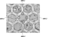
一部の態様では、マイクロキャビティアレイ132が、複数のマイクロキャピラリーウェル(例えば、第1のマイクロキャピラリーウェル500-1、第2のマイクロキャピラリーウェル500-2、…、i個目のマイクロキャピラリーウェル500-iなど)を有するマイクロキャピラリーウェルのアレイを含む。さらに、各マイクロキャピラリーウェル500にはそれぞれの試料が収容される(例えば、第1のマイクロキャピラリーウェル500-1に第1の試料600-1が収容され、第2のマイクロキャピラリーウェル500-2に第2の試料600-2が収容される、など)。一部の態様では、マイクロキャピラリーアレイ132が、長手方向に融着された複数のキャピラリー500、例えば融着シリカキャピラリーを含む。しかしながら、一部の態様では、別の適当な材質がマイクロキャピラリーアレイ132に利用される。例えば、2016年12月12日に出願された米国特許出願第:62/433,210号;2016年12月12日に出願された米国特許出願第:15/376,588号;国際公開公報第:2012/007537号および同第2014/008056号に記載のアレイを参照されたく、これらの各々は参照によりその全体が本明細書に組み入れられる。
In some embodiments, the
一部の態様では、マイクロキャピラリーアレイ132は、例えば、数百万または数十億のシリカキャピラリーを束ねてこれらを熱的プロセスによって一体に融着することを含む方法によって制作される。しかしながら、上記のように、一部の態様では、別の適当な材質がマイクロキャピラリーアレイ132に利用される。一部の態様では、融着プロセスが、例えば、張力下でシングル(single)クラッドファイバーに延伸されたキャピラリー一段(single)延伸ガラスを加熱することを含む。多段(multi)延伸シングルキャピラリーのキャピラリーは、一段延伸ガラスを束ね、加熱し、延伸することにより形成される。したがって、多段延伸マルチキャピラリーは、多段延伸シングルキャピラリーをさらに束ね、加熱し、延伸することにより形成される。延伸ガラスのブロックアセンブリが、多重の多段延伸マルチキャピラリーをプレスブロック状に積層することによりさらに形成される。ブロックプレスブロックは、ブロックアセンブリのプレスブロックを熱および圧力で処理することにより形成される。次いで、ブロックプレスブロックを所定の長さ(例えば、1ミリメートル(mm))に切断することによりブロック形成ブロックが形成される。
In some embodiments, the
一部の態様では、制作方法が、シリカキャピラリーをスライシングすること(例えば、切断すること)をさらに含む。このスライシングにより、単位面積あたり比較的高い密度のマイクロキャピラリーを有するガラスマイクロキャピラリーアレイ132が形成される。一部の態様では、マイクロキャピラリーアレイ132がおよそ1 mmの高さにスライシングされる。一部の態様では、マイクロキャピラリーアレイ132が、各々が1ミクロン(μm)~25 mm、5μm~20 mm、5μm~15 mm、10μm~15 mmまたは10μm~10 mmの範囲の高さを有する複数のマイクロキャピラリーウェル500を含む。しかしながら、本開示はこれに限定されない。例えば、一部の態様では、上記の高さより低いか、または上記の高さより高い複数のマイクロキャピラリーウェル500の高さが想定される。
In some embodiments, the fabrication method further includes slicing (e.g., cutting) the silica capillaries. This slicing forms a
一部の態様では、マイクロキャピラリーアレイ132内の各マイクロキャピラリーウェル500が一様な高さを有する。マイクロキャピラリーアレイ132のこの一様な高さにより、それぞれの各マイクロキャピラリーウェル500の表面(例えば、上面および/または下面)が複数のマイクロキャピラリーウェル500と同一平面上または実質的に同一平面上(例えば、当業者に公知の許容公差の範囲内の同一平面上)になることが可能になる。
In some embodiments, each microcapillary well 500 in the
そのようなプロセスにより、本開示における使用に適した高密度マイクロキャピラリーアレイ132が形成される。一部の態様では、各マイクロキャピラリーウェル500が、内径を有する円筒型形状または実質的に円筒型形状(例えば、半円筒型形状、一様な長さのn個の辺を有する多角形、例えば六角形の形状など)に形成される。そのような態様では、等価な特性寸法、例えば非円形形態の流体力学的直径が、実質的に円筒型のマイクロキャピラリーウェル500の内径を求めるために使用される。一部の態様では、マイクロキャピラリーアレイ132内の各マイクロキャピラリーウェル500の内径が0.5μm~500μm、1μm~500μm、1μm~300μm、25μm~250μm、50μm~250μm、50μm~200μm、75μm~150μm、75μm~125μm、75μm~110μm、80μm~110μm、1μm~100μm、1μm~75μm、1μm~50μm、5μm~50μmまたは1μm~10μmの範囲である。一部の態様では、それぞれの各マイクロキャピラリーウェル500の内径は80μm、90μm、100μm、110μmまたはその組合せである。一部の態様では、それぞれの各マイクロキャピラリーウェル500の内径は1μm、5μm、10μmまたはその組合せである。一部の態様では、それぞれの各マイクロキャピラリーウェル500の内径は一定である。例えば、一部の態様では、マイクロキャピラリーアレイ内のそれぞれの各マイクロキャピラリーウェル500の内径は5μm、10μmまたは100μmである。さらに、一部の態様では、それぞれの各マイクロキャピラリーウェル500の内径は一定である。一部の態様では、対応するマイクロキャピラリーウェル500の内径は第1の端部の第1の直径から第2の端部の第2の直径に移行する。一部の態様では、マイクロキャピラリーウェル500の内径は一定部分と不定部分を含む。
Such a process forms a high
一部の態様では、それぞれの各マイクロキャピラリーウェル500は、マイクロキャピラリーウェル500の内腔である開口領域を含む。一部の態様では、マイクロキャピラリーアレイ132内の1つまたは複数のマイクロキャピラリーウェル500の開口部の割合は、マイクロキャピラリーウェル500の40%~95%、45%~95%、50%~90%、50%~85%、55%~80%、60%~75%、65%~70%または66%~68%の範囲である。一部の態様では、マイクロキャピラリーアレイ132内の1つまたは複数のマイクロキャピラリーウェル500の開口部の割合は、マイクロキャピラリーウェル500の67%である。一部の態様では、マイクロキャピラリーアレイ132内の1つまたは複数のマイクロキャピラリーウェル500の割合は、市販のマイクロキャピラリーアレイ132によって提供されるもの、例えばHamamatsu Photonics K.K.(Japan)のものである。
In some embodiments, each respective microcapillary well 500 includes an open area that is the lumen of the
一部の態様では、マイクロキャピラリーアレイ132内の各マイクロキャピラリーウェル500の各開口領域を含む集合的な開口領域は、各マイクロキャピラリーウェル500の内径が1μm~500μmの範囲で変動する場合、マイクロキャピラリーアレイ132の1平方センチメートル(cm2)あたりのマイクロキャピラリーウェル500の数が同様に460個のマイクロキャピラリーウェル500~1.1・106個のマイクロキャピラリーウェル500またはそれ以上の範囲で変動するように、マイクロキャピラリーアレイ132の開口面積の90%を含む。一部の態様では、マイクロキャピラリーアレイ132の集合的な開口面積は、細孔径(例えば、開口面積)が1μm~500μmの間で変動する場合、マイクロキャピラリーアレイ132の1 cm2あたりのマイクロキャピラリーウェル500の数がおよそ340~800,000超個のマイクロキャピラリーウェル500の範囲で変動するように、開口面積のおよそ67%を含む。一部の態様では、マイクロキャピラリーアレイ132の1 cm2あたりのマイクロキャピラリーウェル500の数は、500個のマイクロキャピラリーウェル500~1・107個のマイクロキャピラリーウェル500の範囲である。
In some embodiments, the collective open area including each open area of each microcapillary well 500 in the
一部の態様では、マイクロキャピラリーアレイ132は、直径10センチメートル(cm)×10 cmの表面積(例えば、マイクロキャピラリーアレイ132の上面および/または下面の表面積)を含む。さらに、マイクロキャピラリーアレイ132内の各マイクロキャピラリーウェル500は、5μmの内径および66%の開口領域を有する。したがって、マイクロキャピラリーアレイ132は、およそ3.3・108個のマイクロキャピラリーウェル500(例えば、第1のマイクロキャピラリーウェル500-1、第2のマイクロキャピラリーウェル500-2、…、(3.3・108)個目のマイクロキャピラリーウェル500-(3.3・108)など)を含む。一部のマイクロキャピラリーアレイでは、アレイの開口面積が開口面積(OA)の90%に至るまでを構成し、そのため、細孔直径が1μm~500μmの間で変動する場合、アレイ1 cmあたりのマイクロキャピラリーの数は、およそ460~1100万超の間で変動する。一部のマイクロキャピラリーアレイでは、アレイの開口面積が開口面積の約67%を構成し、そのため、細孔径が1μm~500μmの間で変動する場合、アレイ1平方cmあたりのマイクロキャピラリーの数は、およそ340~800,000超の間で変動する。一部の態様では、細孔径は、1μm、5μm、10μm 50μm、100μm、250μm 350または500μmである。一部の態様では、細孔径は、5μm~500μmである。一部の態様では、細孔径は、10μm~450μmである。一部の態様では、細孔径は、50μm~500μmである。一部の態様では、細孔径は、100μm~500μmである。一部の態様では、細孔径は、250μm~500μmである。一部の態様では、細孔径は、350μm~500μmである。一部の態様では、細孔径は、100μm~450μmである。一部の態様では、細孔径は、250μm~450μmである。一部の態様では、アレイ1平方cmあたりのマイクロキャピラリーの数は、およそ400;500;1000;2,000;3,000;4,000;5,000;6,000;7,000;8,000;9,000;10,000;20,000;50,000、100,000;200,000;300,000;400,000;500,000;600,000;700,000;または800,000である。一部の態様では、アレイ1平方cmあたりのマイクロキャピラリーの数は、およそ500~800,000の間で変動する。一部の態様では、アレイ1平方cmあたりのマイクロキャピラリーの数は、およそ1000~700,000の間で変動する。一部の態様では、アレイ1平方cmあたりのマイクロキャピラリーの数は、およそ2000~600,000の間で変動する。一部の態様では、アレイ1平方cmあたりのマイクロキャピラリーの数は、およそ10,000~800,000の間で変動する。一部の態様では、アレイ1平方cmあたりのマイクロキャピラリーの数は、およそ10,000~700,000の間で変動する。一部の態様では、アレイ1平方cmあたりのマイクロキャピラリーの数は、およそ50,000~800,000の間で変動する。一部の態様では、アレイ1平方cmあたりのマイクロキャピラリーの数は、およそ50,000~700,000の間で変動する。一部の態様では、アレイ1平方cmあたりのマイクロキャピラリーの数は、およそ100,000~700,000の間で変動する。一部の態様では、アレイ1平方cmあたりのマイクロキャピラリーの数は、およそ100,000~600,000の間で変動する。一部の態様では、アレイ1平方cmあたりのマイクロキャピラリーの数は、およそ100,000~500,000の間で変動する。一部の態様では、アレイ1平方cmあたりのマイクロキャピラリーの数は、およそ500,000~800,000の間で変動する。
In some embodiments, the
一部の態様では、マイクロキャピラリーアレイ132は、熱的制作プロセスにより複数のシリカキャピラリー(例えば、1・109本のキャピラリー)を一体に融着する前に該シリカキャピラリーを接合することにより制作される。融着されたシリカキャピラリーは、およそ0.5 mm超またはおよそ0.5 mmである高さにスライシングされ、比較的高いアスペクト比(例えば、10超もしくは10、25超もしくは25、… 、10,000超もしくは10,000など)を有するガラスマイクロキャピラリーアレイ132が形成される。マイクロキャピラリーアレイ132のアスペクト比はマイクロキャピラリーアレイ500のマイクロキャピラリーウェル500の内径に対する高さの比である。一部の態様では、マイクロキャピラリーアレイ132のアスペクト比は、0.002(例えば、マイクロキャピラリーウェル500が1μmの高さおよび500μmの内径を有する)~50,000(例えば、マイクロキャピラリーウェル500が25 mmの高さおよび0.5μmの内径を有する)、2~50,000、5~50,000、5~25,000、10~25,000、10~15,000、20~15,000または25~10,000の範囲である。一部の態様では、マイクロキャピラリーアレイ132は、市販のマイクロキャピラリーアレイ、例えばHamamatsu Photonics K.K.(日本);Incom,Inc.(マサチューセッツ州);Photonis Technologies,S.A.S.(フランス)Inc.;などから入手可能なマイクロキャピラリーアレイである。
In some embodiments, the
本開示のマイクロキャピラリーアレイ132は特定の数のマイクロキャピラリーウェル500に限定されない。一部の態様では、マイクロキャピラリーアレイ132のマイクロキャピラリーウェル500の数が、スクリーニングされるバリアントタンパク質ライブラリーのサイズに鑑みて決定される。例えば、一部の態様では、システム10の試料ステージ130にいくつかの異なるマイクロキャピラリーアレイ132が収容され得る。一部の態様では、マイクロキャピラリーアレイ132が、1・104個のマイクロキャピラリーウェル500~5・108個のマイクロキャピラリーウェル500またはそれより多くの範囲の数のウェルを含む。しかしながら、本開示はこれに限定されない。
The
一部の態様では、マイクロキャピラリーアレイ132は、100μm~3,000μm、150μm~2,500μm、200μm~2,000μm、500μm~2,500μm、500μm~2,000μm、750μm~1,750μmまたは1,000μm~1,500μmの範囲の厚さを有する。一部の態様では、マイクロキャピラリーアレイ132の厚さがマイクロキャピラリーウェル500の高さに相当する。例えば、マイクロキャピラリーウェル500の高さが1 mmである場合、マイクロキャピラリーアレイ132の対応する厚さはおよそ1 mmである(例えば、試料ステージ130の取り付け機構、例えばブラケットによってもたらされるさらなる厚さを除くマイクロキャピラリーアレイ132の厚さが1 mmである)。
In some embodiments, the
一部の態様では、マイクロキャビティアレイ132が1.5 mmの厚さを有し、それぞれの各マイクロキャピラリーウェル500が150μmの内径を有する。一部の態様では、マイクロキャビティアレイ132が2 mmの厚さを有し、各マイクロキャピラリーウェル500が200μmの内径を有する。一部の態様では、マイクロキャビティアレイ132が1 mmの厚さを有し、各マイクロキャピラリーウェル500が100μmの内径を有する。一部の態様では、マイクロキャビティアレイ132が1 mmの厚さを有し、各マイクロキャピラリーウェル500が10μmの内径を有する。
In some embodiments, the
一部の態様では、それぞれの各マイクロキャピラリーウェル500によってもたらされる量(例えば、それぞれの各マイクロキャピラリーウェル500の試料の量)は、ナノリットル(nL)の範囲(例えば、1 nL~1,000 nL)、ピコリットル(pL)の範囲(例えば、1 pL~1,000 pL)またはフェムトリットル(fL)(例えば、1 fL~1,000 fL)の範囲である。一部の態様では、それぞれの各マイクロキャピラリーウェル500に収容される試料の量は、1ナノリットル(nL)~600 nL、5 nL~500 nL、5 nL~450 nL、5 nL~400 nL、5 nL~350 nL、5 nL~300 nL、5 nL~250 nL、5 nL~200 nL、5 nL~150 nL、5 nL~100 nL、5 nL~90 nL、5 nL~80 nL、5 nL~70 nL、5 nL~60 nL、5 nL~50 nL、5 nL~40 nL、5 nL~30 nL、5 nL~20 nL、5 nL~10 nL、5 nL~8 nLまたは7 nL~8 nLの範囲である。一部の態様では、それぞれの各マイクロキャピラリーウェル500に収容される試料の量は、7.8 nLである。さらに、一部の態様では、それぞれの各マイクロキャピラリーウェル500に収容される試料の量は、50 pL~150 pL、65 pL~110 pL、70 pL~100 pL、70 pL~90 pLまたは70 pL~80 pLの範囲である。一部の態様では、それぞれの各マイクロキャピラリーウェル500に収容される試料の量は、78.5 nLである。さらに、一部の態様では、それぞれの各マイクロキャピラリーウェル500に収容される試料の量は、100 fL~1000 fL、150 fL~1000 fL、200 fL~1000 fL、250 fL~1000 fL、300 fL~1000 fL、350 fL~1000 fL、350 fL~950 fL、350 fL~900 fL、400 fL~900 fL、450 fL~900 fL、500 fL~950 fL、500 fL~800 fL、100 fL~250 fL、150 fL~250 fL、150 fL~200 fLまたは125 fL~175 fLの範囲である。一部の態様では、それぞれの各マイクロキャピラリーウェル500に収容される試料の量は、157 fLである。 In some embodiments, the volume provided by each microcapillary well 500 (e.g., the volume of sample in each microcapillary well 500) is in the nanoliter (nL) range (e.g., 1 nL to 1,000 nL), the picoliter (pL) range (e.g., 1 pL to 1,000 pL), or the femtoliter (fL) range (e.g., 1 fL to 1,000 fL). In some embodiments, the amount of sample contained in each respective microcapillary well 500 ranges from 1 nanoliter (nL) to 600 nL, 5 nL to 500 nL, 5 nL to 450 nL, 5 nL to 400 nL, 5 nL to 350 nL, 5 nL to 300 nL, 5 nL to 250 nL, 5 nL to 200 nL, 5 nL to 150 nL, 5 nL to 100 nL, 5 nL to 90 nL, 5 nL to 80 nL, 5 nL to 70 nL, 5 nL to 60 nL, 5 nL to 50 nL, 5 nL to 40 nL, 5 nL to 30 nL, 5 nL to 20 nL, 5 nL to 10 nL, 5 nL to 8 nL, or 7 nL to 8 nL. In some embodiments, the amount of sample contained in each respective microcapillary well 500 is 7.8 nL. Additionally, in some embodiments, the amount of sample contained in each respective microcapillary well 500 ranges from 50 pL to 150 pL, 65 pL to 110 pL, 70 pL to 100 pL, 70 pL to 90 pL, or 70 pL to 80 pL. In some embodiments, the amount of sample contained in each respective microcapillary well 500 is 78.5 nL. Further, in some embodiments, the amount of sample contained in each respective microcapillary well 500 ranges from 100 fL to 1000 fL, 150 fL to 1000 fL, 200 fL to 1000 fL, 250 fL to 1000 fL, 300 fL to 1000 fL, 350 fL to 1000 fL, 350 fL to 950 fL, 350 fL to 900 fL, 400 fL to 900 fL, 450 fL to 900 fL, 500 fL to 950 fL, 500 fL to 800 fL, 100 fL to 250 fL, 150 fL to 250 fL, 150 fL to 200 fL, or 125 fL to 175 fL. In some embodiments, the amount of sample contained in each microcapillary well 500 is 157 fL.
一部の態様では、マイクロキャピラリーアレイ132内の各マイクロキャピラリーウェル500が、それぞれのマイクロキャピラリーウェル500内に配置された1種または複数種の剤をさらに含む。1種または複数種の剤により、細胞発現アッセイが本開示のシステムおよび方法とともに利用される場合にその細胞発現系のバイアビリティが改善される。一部の態様では、1種または複数種の剤により、マイクロキャピラリーウェル500の内容物を回収する際に細胞の損傷が抑制される。例えば、一部の態様では、内容物の回収がレーザー(例えば、図1のレーザー102)から光のパルスを出射することを含み、1種または複数種の剤により、試料(例えば、図6Bの試料602-i)がレーザー102によって損傷されることが抑制される。
In some embodiments, each microcapillary well 500 in the
一部の態様では、剤は、メチルセルロース(例えば、0.001 wt%~10 wt%の範囲)、デキストラン(例えば、0.5 wt%~10 wt%の範囲)、プルロニックF-68(例えば、0.01 wt%~10 wt%の範囲)、ポリエチレングリコール(“PEG”)(例えば、0.01 wt%~10 wt%の範囲)、ポリビニルアルコール(“PVA”)(例えば、0.01 wt%~10 wt%の範囲)などである。 In some embodiments, the agent is methylcellulose (e.g., in the range of 0.001 wt% to 10 wt%), dextran (e.g., in the range of 0.5 wt% to 10 wt%), Pluronic F-68 (e.g., in the range of 0.01 wt% to 10 wt%), polyethylene glycol ("PEG") (e.g., in the range of 0.01 wt% to 10 wt%), polyvinyl alcohol ("PVA") (e.g., in the range of 0.01 wt% to 10 wt%), or the like.
択一的に、または付加的に、一部の態様では、マイクロキャピラリーアレイ132内の各マイクロキャピラリーウェル500は、増殖添加剤、例えば50%の馴化増殖培地、25%の標準増殖培地または25%の血清などをさらに含む。一部の態様では、馴化増殖培地をおよそ24時間馴化させる。一部の態様では、添加される剤としては、インスリン、トランスフェリン、エタノールアミン、セレン、インスリン様成長因子もしくはその組合せ、または上記の任意の剤の組合せが挙げられる。
Alternatively or additionally, in some embodiments, each microcapillary well 500 in the
また、マイクロキャピラリーウェル500内のスクリーニングアッセイの各成分の濃度は、最適な結果を得るためにアッセイにおいて所望のとおりに調整され得ることを理解されたい。特に、タンパク質、ポリペプチド、核酸、小分子および/または細胞の濃度を、このような成分の間で所望のレベルの結合が得られるように調整することが望ましい場合があり得る。また、結合のレベルは、このような成分間の具体的な親和性に依存し、ここで、高親和性では所与の濃度で高レベルの成分同士の結合がもたらされ、低親和性では所与の濃度で低レベルの成分同士の結合がもたらされる。種々の成分の濃度は、最適なレベルのシグナル出力を得るために同様に調整され得、これは当業者であれば理解されよう。 It should also be understood that the concentration of each component of the screening assay in the microcapillary well 500 may be adjusted as desired in the assay to obtain optimal results. In particular, it may be desirable to adjust the concentration of proteins, polypeptides, nucleic acids, small molecules and/or cells to obtain a desired level of binding between such components. The level of binding will also depend on the specific affinity between such components, where high affinity results in a high level of binding between the components at a given concentration and low affinity results in a low level of binding between the components at a given concentration. The concentrations of the various components may similarly be adjusted to obtain optimal levels of signal output, as would be understood by one of ordinary skill in the art.
一部の態様では、各マイクロキャピラリーウェル500が、マイクロキャピラリーウェル500の第1の端部と第2の端部に開口平面を含む。さらに、一部の態様では、マイクロキャピラリーアレイの対応する各開口平面は、対応する開口平面と同一平面上である。一部の態様では、各マイクロキャピラリーウェル500は、マイクロキャピラリーウェル500の第1の平面から第2の平面への貫通孔を含む。しかしながら、本開示はこれに限定されない。一部の態様では、マイクロキャピラリーアレイ132が、マイクロキャピラリーアレイ132の端部(例えば、表面または表面の一部分)に連結された固相基材を含み、これは、マイクロキャピラリーアレイ132の1つまたは複数のマイクロキャピラリーウェル500の閉鎖端部を形成している。
In some embodiments, each microcapillary well 500 includes an open plane at a first end and a second end of the
一部の態様では、それぞれの試料(例えば、図6Bの試料602-i)がマイクロキャピラリーウェル500内に表面張力によって収容される。例えば、一部の態様では、マイクロキャピラリーウェル500が、マイクロキャピラリーウェル500の第1の端部と第2の端部に開口表面を含み、そのため、試料602が表面張力だけでマイクロキャピラリー500内に収容され、第1および第2の端部は露出している。一部の態様では、表面張力が試料をそれぞれのマイクロキャピラリーウェル500内に保持する唯一の力である。したがって、そのような態様では、レーザービーム(例えば、図1のレーザー102のビーム104)を試料602に向けてパルス発振することによってそれぞれのマイクロキャピラリーウェル500の表面張力が崩壊し、試料602が抽出される。
In some embodiments, each sample (e.g., sample 602-i in FIG. 6B) is contained within the microcapillary well 500 by surface tension. For example, in some embodiments, the microcapillary well 500 includes open surfaces at a first end and a second end of the microcapillary well 500 such that the sample 602 is contained within the
本開示に従ってスクリーニングされ得るライブラリーには、複数の分子ならびにその混合物および/または組合せを含む任意のライブラリーが包含される。一部の態様では、ライブラリーは、生体材料を含む試料を含む。一部の態様では、ライブラリーは、複数の1種または複数種の分子および/または細胞ならびにその混合物および/または組合せを含む試料を含む。一部の態様では、ライブラリーは、複数の1種または複数種のタンパク質、ポリペプチド、核酸、小分子、色素および/または細胞ならびにその混合物および/または組合せを含む試料を含む。一部の態様では、小分子としては任意の分子が挙げられる。一部の態様では、分子としては、タンパク質、ポリペプチド、核酸、小分子および/または色素ならびにその混合物および/または組合せが挙げられる。一部の態様では、ライブラリーは、ポリペプチド、核酸、小分子および/または細胞ならびにその混合物および/または組合せを含む生体材料を含む試料を含む。一部の態様では、ライブラリーは複数の試料を含む。一部の態様では、試料は、ポリペプチド、核酸、小分子、色素および/または細胞ならびにその混合物および/または組合せを含む生体材料を含む。一部の態様では、試料に、スクリーニング対象の少なくとも1個の分子および/または細胞が含まれている。一部の態様では、試料に、スクリーニング対象の少なくとも1個~10個の分子および/または細胞ならびにその混合物および/または組合せが含まれている。一部の態様では、試料に、スクリーニング対象の複数の分子および/または細胞ならびにその混合物および/または組合せが含まれている。一部の態様では、スクリーニング対象の分子を目的分子と称する。一部の態様では、スクリーニング対象の細胞を目的細胞と称する。 Libraries that may be screened according to the present disclosure include any library that includes a plurality of molecules and mixtures and/or combinations thereof. In some embodiments, the library includes a sample that includes a biological material. In some embodiments, the library includes a sample that includes a plurality of one or more molecules and/or cells and mixtures and/or combinations thereof. In some embodiments, the library includes a sample that includes a plurality of one or more proteins, polypeptides, nucleic acids, small molecules, dyes, and/or cells and mixtures and/or combinations thereof. In some embodiments, the small molecules include any molecule. In some embodiments, the molecules include proteins, polypeptides, nucleic acids, small molecules, and/or dyes and mixtures and/or combinations thereof. In some embodiments, the library includes a sample that includes a biological material that includes polypeptides, nucleic acids, small molecules, and/or cells and mixtures and/or combinations thereof. In some embodiments, the library includes a plurality of samples. In some embodiments, the sample includes a biological material that includes polypeptides, nucleic acids, small molecules, dyes, and/or cells and mixtures and/or combinations thereof. In some embodiments, the sample includes at least one molecule and/or cell to be screened. In some embodiments, the sample includes at least 1-10 molecules and/or cells to be screened, as well as mixtures and/or combinations thereof. In some embodiments, the sample includes a plurality of molecules and/or cells to be screened, as well as mixtures and/or combinations thereof. In some embodiments, the molecules to be screened are referred to as molecules of interest. In some embodiments, the cells to be screened are referred to as cells of interest.
本明細書において提供するマイクロキャピラリーアレイ132により、タンパク質、ポリペプチド、核酸、小分子、色素および/または細胞ならびにその混合物および/または組合せを含むライブラリーのスクリーニングが可能になる。一部の態様では、スクリーニング対象の目的分子はタンパク質、ポリペプチド、核酸、小分子、色素、糖質、脂質またはその組合せである。一部の態様では、タンパク質および/またはポリペプチドは、酵素、リガンドおよび受容体からなる群より選択される。例えば、一部の態様では、目的分子は脂質修飾タンパク質またはグリコシル化タンパク質を含む。一部の態様では、目的分子は天然状態のタンパク質を含む。
The
上記のように、諸態様において、本開示によって提供するマイクロキャピラリーアレイ132内の各マイクロキャピラリーウェル500には、マイクロキャピラリーアレイ132内の別のマイクロキャピラリーウェル500の試料の内容物と異なる内容物を有するそれぞれの試料が収容される(例えば、第1のマイクロキャピラリーウェル500-1に第1の試料600-1が収容され、第2のマイクロキャピラリーウェル500-2に第2の試料600-2が収容され、第3のマイクロキャピラリーウェル500-3に第3の試料600-3が収容される、など)。同様に、諸態様において、本開示によって提供するマイクロキャピラリーアレイ132内の1つまたは複数のマイクロキャピラリーウェル500に、マイクロキャピラリーアレイ132内の別のマイクロキャピラリーウェル500の試料の内容物と異なる内容物を有するそれぞれの試料が収容される(例えば、第1のマイクロキャピラリーウェル500-1に第1の試料600-1が収容され、第2のマイクロキャピラリーウェル500-2に第2の試料600-2が収容され、第3のマイクロキャピラリーウェル500-3に第1の試料600-1が収容される、など)。一部の態様では、試料の内容物が、タンパク質、ポリペプチド、核酸、小分子、色素および/または細胞(すなわち、目的分子および/または目的細胞)ならびにその混合物および/または組合せを含む。一部の態様では、スクリーニング用ライブラリーは、区別される特徴を示すバリアントタンパク質、バリアントポリペプチド、バリアント核酸、バリアント小分子、バリアント色素および/または1つもしくは複数のバリアント細胞を含む。一部の態様では、バリアントタンパク質、バリアントポリペプチド、バリアント核酸、バリアント小分子、バリアント色素および/または1つもしくは複数のバリアント細胞は区別される特徴を示す。このように区別される特徴が示されることにより、各マイクロキャピラリーウェル500に、マイクロキャピラリーアレイ132内のその他の各々のマイクロキャピラリーウェル500に収容される対応する試料と異なる目的分子および/または目的細胞を含むそれぞれの試料を含めることが可能になる。一部の態様では、マイクロキャピラリーアレイ132内の1つまたは複数のマイクロキャピラリーウェル500は、マイクロキャピラリーアレイ132内の少なくとも1つの他のマイクロキャピラリーウェル130に収容された別の試料と同じ目的分子および/または目的細胞を含むそれぞれの試料を含む(例えば、それぞれの試料が比較のために少なくとも二連である)。
As noted above, in various embodiments, each microcapillary well 500 in a
一部の態様では、マイクロキャピラリーアレイ132内のライブラリー内のスクリーニング対象のタンパク質および/またはポリペプチドは、1種または複数種のバリアントタンパク質および/またはポリペプチドを含む。バリアントタンパク質には、少なくとも1つの特徴および特長に基づいて相互に区別可能であるタンパク質およびポリペプチドが包含される。一部の態様では、バリアントタンパク質および/またはポリペプチドは、異なるアミノ酸配列を示す、異なるアミノ酸配列の長さを示す、異なる方法によって産生/生成される、異なる活性を示す、異なる化学修飾を示す、異なる翻訳後修飾を示す、またはその組合せである。一部の態様では、バリアントタンパク質は、本開示のマイクロキャピラリーアレイ132を利用するスクリーニングおよび解析に供されているバリアントタンパク質および/またはポリペプチドの集団を含む。一部の態様では、バリアントタンパク質および/またはポリペプチドの集団は、マイクロキャピラリーアレイ132内でちょうどよく分布可能なタンパク質の任意の集団を含む。
In some embodiments, the proteins and/or polypeptides to be screened in the library in the
一部の態様では、マイクロキャビティアレイ内のスクリーニング対象のライブラリー内の核酸は、1種または複数種のバリアント核酸を含む。バリアント核酸には、少なくとも1つの特徴および特長に基づいて相互に区別可能である核酸が包含される。一部の態様では、バリアント核酸は、異なるヌクレオチド配列、異なるヌクレオチド配列の長さ、異なるメチル化パターン、異なる化学修飾を含む、異なる方法によって作製/生成される、他の区別される修飾を示す、またはその組合せである。一部の態様では、核酸は、本開示のマイクロキャピラリーアレイ132を利用するスクリーニングおよび解析に供されているバリアント核酸の集団のものである。一部の態様では、バリアント核酸の集団は、マイクロキャピラリーアレイ132内でちょうどよく分布可能な核酸の任意の集団を含む。
In some embodiments, the nucleic acids in the library to be screened in the microcavity array include one or more variant nucleic acids. Variant nucleic acids include nucleic acids that are distinguishable from one another based on at least one characteristic and feature. In some embodiments, the variant nucleic acids exhibit different nucleotide sequences, different nucleotide sequence lengths, different methylation patterns, other distinct modifications made/produced by different methods, including different chemical modifications, or combinations thereof. In some embodiments, the nucleic acids are from a population of variant nucleic acids that are subject to screening and analysis using the
一部の態様では、マイクロキャピラリーアレイ132内のスクリーニング対象のライブラリー内の小分子は、バリアント小分子および/または異なる小分子を含む。バリアント小分子には、少なくとも1つの特徴および特長に基づいて相互に区別可能である小分子が包含される。一部の態様では、バリアント小分子は、異なる構造を含む、異なる方法によって作製/生成されたものである、異なる化学修飾を有する、他の区別される異なる特長を示す、またはその組合せである。一部の態様では、小分子は相互の誘導体である。一部の態様では、小分子は、本開示のマイクロキャピラリーアレイ132を利用するスクリーニングおよび解析に供されている小分子の集団のものである。一部の態様では、小分子の集団は、マイクロキャピラリーアレイ132内でちょうどよく分布可能な小分子の任意の集団を含む。
In some embodiments, the small molecules in the library to be screened in the
一部の態様では、マイクロキャビティアレイ内のスクリーニング対象のライブラリー内の細胞は、バリアント細胞および/または多様な種類の細胞を含む。バリアント細胞には、少なくとも1つの特徴および特長に基づいて相互に区別可能である細胞が包含される。一部の態様では、細胞は、異なる試料に由来する、異なる患者に由来する、異なる疾患に由来する、異なる化学修飾を有する、遺伝子組み換えされている、またはその組合せである。一部の態様では、細胞は、真核生物細胞および/または原核生物細胞を含む。一部の態様では、細胞は、哺乳動物細胞(例えば、ヒト細胞、齧歯類細胞、例えばマウス細胞およびラット細胞、鳥類細胞、例えばニワトリ細胞など)、細菌細胞、真菌細胞、例えば酵母細胞、昆虫細胞または植物細胞を含む。一部の態様では、哺乳動物細胞は、血液細胞、リンパ球細胞、細胞脾、リンパ節細胞、骨髄細胞またはその組合せを含む。一部の態様では、細胞は、本開示のマイクロキャピラリーアレイ132を利用するスクリーニングおよび解析に供されている細胞の集団のものである。一部の態様では、細胞の集団は、マイクロキャピラリーアレイ132内で適切に分布可能な細胞の任意の集団を含む。
In some embodiments, the cells in the library to be screened in the microcavity array include variant cells and/or various types of cells. Variant cells include cells that are distinguishable from one another based on at least one characteristic and feature. In some embodiments, the cells are from different samples, from different patients, from different diseases, have different chemical modifications, are genetically modified, or combinations thereof. In some embodiments, the cells include eukaryotic cells and/or prokaryotic cells. In some embodiments, the cells include mammalian cells (e.g., human cells, rodent cells such as mouse cells and rat cells, avian cells such as chicken cells, etc.), bacterial cells, fungal cells such as yeast cells, insect cells, or plant cells. In some embodiments, the mammalian cells include blood cells, lymphocyte cells, spleen cells, lymph node cells, bone marrow cells, or combinations thereof. In some embodiments, the cells are from a population of cells being subjected to screening and analysis utilizing the
一部の態様では、タンパク質、ポリペプチド、核酸および/または細胞の集団がマイクロキャピラリーアレイ132内に分布しており、各マイクロキャピラリーウェル500に少数の異なるバリアントタンパク質、バリアントポリペプチド、バリアント核酸および/または細胞が収容されることが可能になっている。一部の態様では、それぞれの各マイクロキャピラリーウェル500に単一の異なるバリアントのタンパク質、バリアントポリペプチド、バリアント核酸および/または細胞が含まれる。一部の態様では、それぞれの各マイクロキャピラリーウェル500に単一の異なるバリアントタンパク質が含まれる。一部の態様では、それぞれの各マイクロキャピラリーウェル500に単一の異なるバリアントポリペプチドが含まれる。一部の態様では、それぞれの各マイクロキャピラリーウェル500にマイクロキャビティ1つあたり単一の異なるバリアント核酸が含まれる。一部の態様では、それぞれの各マイクロキャピラリーウェル500にマイクロキャビティ1つあたり単一の異なる細胞が含まれる。バリアントタンパク質、バリアントポリペプチド、バリアント核酸および/または細胞の集団は、試料内の他の成分との組合せで選び出される。
In some embodiments, the population of proteins, polypeptides, nucleic acids and/or cells are distributed within the
一部の態様では、マイクロキャピラリーアレイ132内の各マイクロキャピラリーウェル500は、バリアントタンパク質の集団からの0種類の異なるバリアント~10種類の異なるバリアント、0種類の異なるバリアント~7種類の異なるバリアント、0種類の異なるバリアント~5種類の異なるバリアント、0種類の異なるバリアント~4種類の異なるバリアント、0種類の異なるバリアント~3種類の異なるバリアント、0種類の異なるバリアント~2種類の異なるバリアント、または0種類の異なるバリアント~1種類の異なるバリアントの範囲の、異なるバリアントタンパク質、バリアントポリペプチド、バリアント核酸および/または細胞を含む。
In some embodiments, each microcapillary well 500 in the
したがって、一部の態様では、バリアントタンパク質は、可溶性タンパク質、例えば細胞発現系によって分泌される可溶性タンパク質を含む。例示的な可溶性バリアントタンパク質は、抗体および抗体断片、択一的なタンパク質骨格、例えばジスルフィド結合型ペプチド骨格、細胞表面受容体タンパク質の細胞外ドメイン、受容体リガンド、例えばGタンパク質共役受容体リガンド、他のペプチドホルモン、レクチンなどを含む。一部の態様では、本開示のシステムおよび方法を用いてスクリーニングされるバリアントタンパク質は、スクリーニングアッセイ後に識別されるために、それぞれのバリアントタンパク質を発現する細胞またはウイルスに共有結合されている必要はない。それぞれのマイクロキャピラリーウェル500の内容物の回収後、所望のバリアントタンパク質の発現を担う細胞またはウイルスのクローンを増殖させることにより、それぞれのバリアントタンパク質の識別および特性評価が可能である。バリアントタンパク質を該タンパク質の細胞またはウイルス粒子の表面上の分子との融合によってディスプレイさせるスクリーニングアッセイとは異なり、本開示において識別されるバリアントタンパク質は、その識別の前または後のいずれかで、なんらかの様式で改変する必要はない。したがって、スクリーニングにおいて観察されるバリアントタンパク質の活性は、後の適用における該タンパク質の実際の活性を表す可能性が高くなる。また、スクリーニングの前にバリアントタンパク質またはポリペプチドを改変する必要がないことにより、より効率的なスクリーニングが可能になり、ライブラリーの調製のためのコストと時間が節約される。 Thus, in some embodiments, the variant proteins include soluble proteins, e.g., soluble proteins secreted by a cellular expression system. Exemplary soluble variant proteins include antibodies and antibody fragments, alternative protein scaffolds, e.g., disulfide-linked peptide scaffolds, extracellular domains of cell surface receptor proteins, receptor ligands, e.g., G protein-coupled receptor ligands, other peptide hormones, lectins, and the like. In some embodiments, the variant proteins screened using the systems and methods of the present disclosure do not need to be covalently attached to the cells or viruses expressing the respective variant proteins in order to be identified following a screening assay. After recovery of the contents of each microcapillary well 500, each variant protein can be identified and characterized by growing a clone of the cell or virus responsible for expression of the desired variant protein. Unlike screening assays in which the variant protein is displayed by fusion of the protein with a molecule on the surface of a cell or viral particle, the variant proteins identified in the present disclosure do not need to be modified in any manner, either before or after their identification. Thus, the activity of the variant protein observed in the screen is more likely to represent the actual activity of the protein in the subsequent application. Also, not having to modify the variant protein or polypeptide prior to screening allows for more efficient screening and saves costs and time for library preparation.
一部の態様では、スクリーニング対象のバリアントタンパク質は、膜結合タンパク質、例えば典型的には発現系内の細胞またはウイルス粒子の表面と結合しているタンパク質を含む。一部の態様では、バリアントタンパク質およびその目的分子が生体組織内の2つの細胞間の相互作用を媒介している場合、細胞結合バリアントタンパク質のスクリーニングが望ましい。一部の態様では、従来より「創薬可能でない」目的タンパク質、例えばGタンパク質共役受容体またはイオンチャネルなどとの相互作用に関するスクリーニングにおいて細胞結合バリアントタンパク質をスクリーニングできることが望ましい。また、この場合も、スクリーニングの前にバリアントタンパク質またはポリペプチドを改変する必要がないことにより、より効率的なスクリーニングが可能になり、これによりライブラリーの調製時の資源が節約される。 In some embodiments, the variant proteins to be screened include membrane-bound proteins, e.g., proteins that are typically bound to the surface of a cell or viral particle in an expression system. In some embodiments, screening for cell-bound variant proteins is desirable when the variant protein and its molecule of interest mediate an interaction between two cells in a living tissue. In some embodiments, it is desirable to be able to screen cell-bound variant proteins in screens for interactions with traditionally "non-druggable" proteins of interest, such as G-protein coupled receptors or ion channels. Again, not having to modify the variant protein or polypeptide prior to screening allows for more efficient screening, thereby saving resources during library preparation.
一部の態様では、スクリーニング対象のバリアント核酸は、任意の核酸またはポリヌクレオチド、例えばタンパク質に結合するか、あるいはタンパク質と相互作用する核酸またはポリヌクレオチドを含む。また、この場合も、スクリーニングの前に核酸またはポリヌクレオチドを改変する必要がないことにより、より効率的なスクリーニングが可能になり、ライブラリーの調製のためのコストと時間が節約される。 In some embodiments, the variant nucleic acids to be screened include any nucleic acid or polynucleotide, such as a nucleic acid or polynucleotide that binds to or interacts with a protein. Again, not having to modify the nucleic acid or polynucleotide prior to screening allows for more efficient screening and saves costs and time for library preparation.
一部の態様では、スクリーニング対象のタンパク質は、抗体、抗体断片、例えばFc、または抗体融合体、例えばFc融合体などである。一部の態様では、抗体または抗体断片が標識され得る。 In some embodiments, the protein to be screened is an antibody, an antibody fragment, such as Fc, or an antibody fusion, such as an Fc fusion. In some embodiments, the antibody or antibody fragment can be labeled.
一部の態様では、方法において、スクリーニング対象の目的分子に結合する抗体の使用が用いられる。一部の態様では、抗体は、目的分子に結合させるために使用されるような標識された一次抗体または標識された二次抗体である。一次抗体は典型的には、関心対象の抗原に直接結合する抗体であるとみなされ、一方、二次抗体は典型的には、一次抗体を標識する目的のための該一次抗体の定常領域に結合する抗体であるとみなされる。したがって、二次抗体は高い頻度で、フルオロフォアまたは他の検出可能な標識で標識されるか、あるいは検出可能なシグナルを生成することができる酵素で標識される。二次抗体は一般的に、異なる種の一次抗体に特異的である。例えば、一部の態様では、ヤギまたは他の動物種を用いて、マウス、ニワトリ、ウサギまたは該動物種由来の抗体以外のほぼ任意の一次抗体に対する二次抗体を生成させ、これは当業者には理解されよう。一部の態様では、標識抗体が一次抗体または二次抗体である。一部の態様では、標識抗体が蛍光抗体または酵素連結抗体である。 In some aspects, the method employs the use of an antibody that binds to the molecule of interest being screened. In some aspects, the antibody is a labeled primary antibody or a labeled secondary antibody that is used to bind to the molecule of interest. A primary antibody is typically considered to be an antibody that directly binds to the antigen of interest, while a secondary antibody is typically considered to be an antibody that binds to the constant region of the primary antibody for the purpose of labeling the primary antibody. Thus, secondary antibodies are frequently labeled with a fluorophore or other detectable label, or with an enzyme that can generate a detectable signal. Secondary antibodies are generally specific to a primary antibody of a different species. For example, in some aspects, goats or other animal species are used to generate secondary antibodies against mouse, chicken, rabbit, or almost any primary antibody other than antibodies from the animal species, as would be understood by one of skill in the art. In some aspects, the labeled antibody is a primary antibody or a secondary antibody. In some aspects, the labeled antibody is a fluorescent antibody or an enzyme-linked antibody.
当業者に理解され得るように、例えば蛍光抗体が本開示のシステムおよび方法において使用される場合、それぞれのマイクロキャピラリーウェル500内で溶液中に遊離状態で残存している(すなわち、バリアントタンパク質に結合していないか、または目的分子に結合していないバリアントタンパク質に結合しているかのいずれか)なんらかの過剰なレポーター要素が発するシグナルは、バリアントタンパク質を介して目的分子と結合しているレポーター要素のシグナルに勝るほど高くないのがよい(例えば、非結合蛍光抗体を参照のこと)。しかしながら、そのようなバックグラウンドシグナルは、マイクロキャピラリー内の標識抗体または他のレポーター要素の溶液中濃度を制限することによって最小限にすることができる。また、一部の態様では、スクリーニング方法でのシグナルを、蛍光顕微鏡を用いて測定する場合、顕微鏡は、目的分子と結合していないレポーター要素によるバックグラウンドシグナルが最小限となるように、目的分子の場所をブラケット(bracket)する比較的浅い被写界深度(例えば、目的細胞が重力沈降によって下端部に沈殿している場合、マイクロキャピラリーウェル500の該下端部)がイメージングされるように構成される。 As can be appreciated by those skilled in the art, when fluorescent antibodies, for example, are used in the disclosed systems and methods, any excess reporter elements remaining free in solution in each microcapillary well 500 (i.e., either unbound to a variant protein or bound to a variant protein that is not bound to a molecule of interest) should not produce a signal high enough to overcome the signal of the reporter elements bound to the molecule of interest via the variant protein (see, e.g., unbound fluorescent antibodies). However, such background signal can be minimized by limiting the solution concentration of the labeled antibody or other reporter element in the microcapillary. Also, in some embodiments, when the signal in the screening method is measured using a fluorescent microscope, the microscope is configured to image a relatively shallow depth of field that brackets the location of the molecule of interest (e.g., the bottom end of the microcapillary well 500 if the cell of interest has settled to the bottom end by gravitational sedimentation) so that background signal from reporter elements not bound to the molecule of interest is minimized.
一部の態様では、マイクロキャピラリーアレイ132内のマイクロキャピラリーウェル500の数がスクリーニング対象のライブラリーのサイズに鑑みて決定される。一部の態様では、ライブラリーのサイズは、1・104~5・108個の範囲のタンパク質、ポリペプチド、核酸、小分子および/または細胞ならびにその混合物および/または組合せである。しかしながら、本開示はこれに限定されない。
In some embodiments, the number of
当業者であれば、それぞれの各マイクロキャピラリーウェル500には典型的には、具体的なタンパク質、ポリペプチド、核酸、小分子および/または細胞ならびにその混合物および/または組合せの供給源および発現レベルに応じて複数コピーの同じタンパク質、ポリペプチド、核酸、小分子および/または細胞が含まれることが理解され得よう。一部の態様では、それぞれの各マイクロキャピラリーウェル500に、特定のタンパク質、ポリペプチド、核酸、小分子、および/または細胞の複数の分子が、これらのタンパク質、ポリペプチド、核酸、小分子および/または細胞ならびにその混合物および/または組合せがどのようにしてそれぞれのマイクロキャピラリーウェル500に送達されるか、またはどのようにしてそれぞれのマイクロキャピラリーウェル500内で発現されるかに応じて、5・102~1・1010個の範囲で含まれる。一部の態様では、それぞれのマイクロキャピラリーウェル500に収容される試料中のタンパク質、ポリペプチド、核酸、小分子および/または細胞の種類の数は、1種類~10種類、1種類~5種類または1種類~4種類の範囲である。 One of skill in the art will appreciate that each respective microcapillary well 500 typically contains multiple copies of the same protein, polypeptide, nucleic acid, small molecule, and/or cell depending on the source and expression level of the particular protein, polypeptide, nucleic acid, small molecule, and/or cell, and mixtures and/or combinations thereof. In some embodiments, each respective microcapillary well 500 contains a plurality of molecules of a particular protein, polypeptide, nucleic acid, small molecule, and/or cell ranging from 5·10 2 to 1· 10 10 depending on how the protein, polypeptide, nucleic acid, small molecule, and/or cell, and mixtures and/or combinations thereof are delivered to or expressed within each respective microcapillary well 500. In some embodiments, the number of types of proteins, polypeptides, nucleic acids, small molecules, and/or cells in a sample contained within each respective microcapillary well 500 ranges from 1 to 10, 1 to 5, or 1 to 4.
タンパク質、ポリペプチド、核酸および/または小分子ならびにその混合物および/または組合せの集団は典型的には、遺伝子ライブラリーを用いて生物学的発現系内で、例えばインビトロ(例えば、無細胞)発現系内またはインビボ発現系もしくは細胞発現系内で生成させる。一部の態様では、タンパク質、ポリペプチド、核酸および/または小分子ならびにその混合物および/または組合せの集団を、任意の公知の合成方法によって生成させる。例示的な細胞発現系としては、例えば、動物由来の系(例えば、哺乳動物由来の系)、真菌由来の系(例えば、酵母由来の系)、細菌由来の系、昆虫由来の系または植物由来の系が挙げられる。一部の態様では、発現系が哺乳動物由来の系または酵母由来の系である。発現系は、細胞系であれ無細胞系であれ典型的には、バリアントタンパク質の集団をコードしている遺伝物質のライブラリーを含む。細胞発現系では、望ましい表現型を有する細胞、例えば、関心対象の具体的なバリアントタンパク質、例えば固定化された目的分子と高親和性で結合することができるバリアントタンパク質を発現する細胞を培養して増殖させることができ、したがって、該細胞によって発現される関心対象のタンパク質の識別および特性評価が容易になり、簡素化されるという利点がもたらされる。 The population of proteins, polypeptides, nucleic acids, and/or small molecules, and mixtures and/or combinations thereof, are typically produced in a biological expression system, such as in an in vitro (e.g., cell-free) expression system or in an in vivo or cellular expression system, using a gene library. In some embodiments, the population of proteins, polypeptides, nucleic acids, and/or small molecules, and mixtures and/or combinations thereof, are produced by any known synthetic method. Exemplary cellular expression systems include, for example, animal-derived systems (e.g., mammalian-derived systems), fungal-derived systems (e.g., yeast-derived systems), bacterial-derived systems, insect-derived systems, or plant-derived systems. In some embodiments, the expression system is a mammalian-derived system or a yeast-derived system. The expression system, whether cellular or cell-free, typically includes a library of genetic material encoding a population of variant proteins. Cellular expression systems offer the advantage that cells with a desired phenotype, e.g., cells expressing a specific variant protein of interest, e.g., a variant protein capable of binding with high affinity to an immobilized molecule of interest, can be cultured and grown, thus facilitating and simplifying the identification and characterization of the protein of interest expressed by the cells.
大集団のタンパク質、ポリペプチド、核酸および/または小分子ならびにその混合物および/または組合せをコードしている遺伝子ライブラリーはバイオエンジニアリングの技術分野において周知である。そのようなライブラリーは多くの場合、好都合な特性、例えば目的分子に対する高親和性結合、安定性、高発現、または特定の分光学的活性、例えば蛍光もしくは酵素活性を有するタンパク質を識別するための定向進化のプロセスに依存する系において、利用される。多くの場合、ライブラリーは、宿主の発現系由来の、例えば細胞内局在を導くタンパク質断片由来の配列を有する融合遺伝子を含み、ここで、発現されたバリアント融合タンパク質集団は、ターゲティング断片によって、該バリアントタンパク質集団の活性スクリーニングの目的のために細胞またはウイルス粒子の特定の場所に指向させられる。大量数のバリアントタンパク質、ポリペプチド、核酸、小分子および/または細胞(例えば、106個のバリアント、108個のバリアント、1010個のバリアント、1012個のバリアントまたはさらにより多くのバリアント)ならびにその混合物および/または組合せを、常套的なバイオエンジニアリング手法を用いて生成させることができ、これは当技術分野において周知である。一部の態様では、ライブラリーが市販の供給元から購入される。 Gene libraries encoding large populations of proteins, polypeptides, nucleic acids and/or small molecules, as well as mixtures and/or combinations thereof, are well known in the field of bioengineering. Such libraries are often utilized in systems that rely on the process of directed evolution to identify proteins with favorable properties, such as high affinity binding to molecules of interest, stability, high expression, or specific spectroscopic activity, such as fluorescence or enzymatic activity. In many cases, libraries contain fusion genes with sequences from the host's expression system, such as protein fragments that direct intracellular localization, where the expressed variant fusion protein population is directed by the targeting fragment to a specific location in a cell or virus particle for the purpose of activity screening of the variant protein population. Large numbers of variant proteins, polypeptides, nucleic acids, small molecules and/or cells (e.g., 106 variants, 108 variants, 1010 variants, 1012 variants or even more variants), as well as mixtures and/or combinations thereof, can be generated using routine bioengineering techniques, which are well known in the art. In some embodiments, the library is purchased from a commercial source.
しかしながら、本開示はこれに限定されない。一部の態様では、試料は、無機物質または有機物質と無機物質の組合せ、例えば環境供給源(例えば、土、水、植生など)を含む。一部の態様では、顕微鏡ステージの取り付けにより、レーザーを用いた前記マイクロキャピラリーアレイ内容物の回収が可能になる。一部の態様では、回収された内容物は細胞を含む。一部の態様では、回収された内容物は生細胞および/または死(例えば、死んだ)細胞を含む。一部の態様では、回収された細胞は1種または複数種の核酸の存在についてさらに解析される。一部の態様では、回収された細胞は1種または複数種のアミノ酸の存在についてさらに解析される。 However, the disclosure is not so limited. In some embodiments, the sample comprises inorganic material or a combination of organic and inorganic material, such as an environmental source (e.g., soil, water, vegetation, etc.). In some embodiments, the microscope stage attachment allows for recovery of the microcapillary array contents using a laser. In some embodiments, the recovered contents comprise cells. In some embodiments, the recovered contents comprise live cells and/or dead (e.g., dead) cells. In some embodiments, the recovered cells are further analyzed for the presence of one or more nucleic acids. In some embodiments, the recovered cells are further analyzed for the presence of one or more amino acids.
マイクロキャピラリーアレイ132およびマイクロキャピラリーウェル500の詳細を開示してきたので、次に、本開示の一態様によるサンプルシステム10の光ガイドシステム100に関する詳細を開示する。
Having disclosed details of the
図1を参照されたい。システム10は、マイクロキャピラリーアレイ132の内容物の回収および/またはイメージングを容易にする光ガイドシステム100を含む。システム10はサンプルステージ130をさらに含み、これはマイクロキャピラリーアレイ132を収容しており、一部の態様ではマイクロキャピラリーアレイ132の内容物の回収および/またはイメージングを容易にするのを補助する。
See FIG. 1.
一部の態様では、システム10は、メモリおよびプロセッサを有する1つまたは複数のコンピュータ(例えば、コンピュータシステム)を含む。メモリには、1つまたは複数のプロセッサによる実行のための1つまたは複数のプログラムが格納される。1つまたは複数のプログラムは、単独または集合的に光ガイドシステム100および/またはサンプルステージ130を利用するための命令を含む。一部の態様では、1つまたは複数の命令が、光ガイドシステム100の光源に対する位置決め命令(例えば、光ガイドシステム100の光学アセンブリの構成要素の位置決めに対する位置決め命令など)、光源に対する動作命令(例えば、活性化および失活命令、強度命令、パルスパラメータ命令など)、ならびに試料ステージ130に関する同様の命令(例えば、位置決め命令)を含む。
In some embodiments,
ガイドシステム100は、電磁放射線をターゲットに向けて指向させて該ターゲット(例えば、マイクロキャピラリーアレイ132)の一部分に照射する1つまたは複数の光源を含む。一部の態様では、1つまたは複数の光源の第1のサブセットはマイクロキャピラリーウェル500の試料(例えば、図6Bの500-iの細胞604-1)の内容物の抽出および回収を容易にし、一方、1つまたは複数の光源の第2のサブセットは試料のイメージングを容易にする。一部の態様では、光源の第1および第2のサブセットが協同で動作し、試料の回収時のマイクロキャピラリーアレイ132のリアルタイムイメージングを可能にする。一部の態様では、光ガイドシステム100が、システム10の1つまたは複数の光依存性構成要素のための対応するガイドシステムを含む。例えば、一部の態様では、ガイドシステム100は、少なくとも、レーザー102の動作およびレーザー102のビーム104の位置決めにおける使用のためのレーザーガイドシステム100を含む。一部の態様では、ガイドシステム100は、少なくとも、1つまたは複数のカメラ120の動作における使用のためのイメージングガイドシステムを含む。
The
各マイクロキャピラリーウェル500の直径のサイズが比較的小さいため(例えば、1 cm未満の直径)、光ガイドシステム100には、マイクロキャピラリーアレイ132の内容物の回収の際にマイクロキャピラリーアレイ132内のそれぞれのマイクロキャピラリーウェル500を正確かつ精密に標的とするように、光104の集束ビームが利用される。したがって、一部の態様では、光源は、電磁放射線のコヒーレントビーム104を出射するレーザー102を含む。一部の態様では、レーザー102はレーザーダイオードである。一部の態様では、レーザー102は連続波レーザーまたは好ましくはパルスレーザーである。
Due to the relatively small size of the diameter of each microcapillary well 500 (e.g., less than 1 cm in diameter), the
レーザー102は、パルスの周波数(例えば、1ヘルツ(Hz)で1秒間に1個のパルスがもたらされる、など)を規定するパルス周期を含む。一部の態様では、レーザーのパルス周期は、1 Hz~60,000 Hz(例えば、60キロヘルツ(kHz))、100 Hz~60 kHz、500 Hz~60 kHz、500 Hz~50 kHz、500 Hz~40 kHz、1 kHz~40 kHz、1 kHz~30 kHz、1 kHz~27.5 kHz、1 kHz~25 kHz、1.5 kHz~25 kHz、2 kHz~25 kHz、1 kHz~20 kHz、2 kHz~20 kHz、2.5 kHz~20 kHz、5 kHz~25 kHz、5 kHz~20 kHz、10 kHz~40 kHzまたは15 kHz~25 kHzの範囲である。一部の態様では、レーザー102のパルス周期は20 kHzである。
The
一部の態様では、レーザー102により、紫外スペクトルの光104(例えば、UVレーザー)または可視スペクトルの光104(例えば、可視スペクトルレーザー)が出射される。一部の態様では、レーザー102から出射されるビーム104は213ナノメートル(nm)~1380 nmの範囲である。一部の態様では、レーザー102から出射されるビーム104は、355 nm、375 nm、404 nm、405 nm、406 nm、450 nm、462 nm、473 nm、488 nm、514 nm、520 nm、532 nm、633 nm、635 nm、637 nm、638 nm、639 nm、640 nm、642 nm、650 nm、658 nm、660 nm、670 nm、685 nm、690 nmおよび1064 nmからなる群より選択される。一部の態様では、ビーム104の波長は、レーザー102のターゲットに応じて選択される。
In some embodiments, the
一部の態様では、レーザー102は市販のレーザーである。一部の態様では、市販のレーザー102としては、例えば、Thorlabs(例えば、Thorlabs.com/newgrouppage9.cfm?objectgroup_id=7のワールドワイドウェブに記載されたものを参照されたい);Spectra-Physics(例えば、spectra-physics.com/products/q-switched-lasers/explorer-oneのワードワイドウェブに記載されたものを参照されたい);および/またはIntegrated Optics(例えば、integratedoptics.com/products/nanosecond-lasersに記載されたものを参照されたい)から入手可能なものが挙げられる。
In some embodiments, the
一部の態様では、システム10のガイドシステム100は、1つもしくは複数の光源からのビーム(例えば、レーザー102のビーム104、蛍光光源116のビーム118など)および/または1つもしくは複数のカメラ120の視野を遮る対物レンズ112を含む。例えば、図1に示すように、一部の態様では、対物レンズ112が試料ステージ130と1つまたは複数の光源との間に置かれ、対物レンズ112で1つまたは複数の光源の各々からの光を集めることが可能になる。一部の態様では、対物レンズ112は改良された顕微鏡に基づいたものである。一部の態様では、顕微鏡により、高い収光効率でフロントエンド画像収集および光学ズームがもたらされる。一部の態様では、対物レンズ10が1~100倍の光学倍率、2~100倍の光学倍率、4~100倍の光学倍率、4~80倍の光学倍率または4~40倍の光学倍率の範囲の光学倍率をもたらす。一部の態様では、対物レンズ112の光学倍率は10倍である。
In some embodiments, the guiding
一部の態様では、対物レンズ112は、試料ステージ130が対物レンズ112に対して相対的に位置決めされるように固定される。一部の態様では、対物レンズ112は、対物レンズ112の位置決めを可能にするモーター114に連結される。一部の態様では、モーター114により、対物レンズ112に対して1自由度がもたらされる。一部の態様では、モーター114によってもたらされる該1自由度は、ガルバノメーターシステム106によってもたらされる自由度と異なる(例えば、ガルバノメーターシステム106はX軸とY軸における2並進自由度をもたらし、モーター114はビーム104を再指向するためのZ軸における1並進自由度をもたらす)。したがって、一部の態様では、対物レンズ112は、ビーム104が、対物レンズ112を通過した後マイクロキャピラリーアレイ132に向けて0度(°)またはおよそ約0°の入射角で指向させられるように、試料ステージ130の対応する平面に平行な平面上に固定される。この入射角の制限により、対物レンズ112によってマイクロキャピラリーアレイ132の単一の視野がもたらされることが可能になる。そのような態様では、該単一の視野により、レーザー102を、ビーム104の焦点を再び合わせる必要なく、あるいはレーザー102を調整する必要なく第1のターゲットから第2のターゲットに位置決めすることが可能になる。したがって、一部の態様では、ガイドシステム100および試料ステージ130が、試料ステージ130の移動によって対物レンズの新たな視野がもたらされるように互いに対して相対的に横移動する。さらに、入射角の制限を伴うこの構成により、マイクロキャピラリーウェル500からの内容物の抽出の際(例えば、同時)のマイクロキャピラリーアレイのイメージングが可能になる。
In some embodiments, the
一部の態様では、1つまたは複数の光源は、対応する光のビーム118を出射する蛍光光源116を含む。一部の態様では、蛍光光源116は、UV波長スペクトル(例えば、10 nm~400 nmの範囲)の光のビーム118を出射する。
In some embodiments, the one or more light sources include a fluorescent
一部の態様では、1つまたは複数の光源は明視野光源126を含む。明視野光源126は、蛍光光源116に対してマイクロキャピラリーアレイ132の反対の端部に配置され、そのため、マイクロキャピラリーアレイ132は蛍光光源116のビーム118と明視野光源126間に置かれる。一部の態様では、1つまたは複数の光源からの出射光は、指定されたマイクロキャピラリーウェル500の試料から検出ユニット(例えば、明視野光源126)に指向させられる。
In some embodiments, the one or more light sources include a bright field
一部の態様では、レーザーガイドシステム100およびマイクロキャピラリーアレイ132が各々、固定された位置に配置され、そのため、光学縦列(例えば、レーザースキャンアセンブリ)により、レーザーのビーム104を指定されたターゲット(例えば、第1のマイクロキャピラリーウェル500-1、第1のマイクロキャピラリーウェル500-1の一部分など)に向けてガイドすることが容易になる。例えば、一部の態様では、サンプルステージ130にはマイクロキャピラリー132が固定された位置に収容され、マイクロキャピラリーアレイ132の内容物の回収および/またはイメージングの際の位置の移動ならびにマイクロキャピラリーアレイ132の内容物に対する物理的崩壊が抑制される。
In some embodiments, the
一部の態様では、サンプルステージ130がマイクロキャピラリーアレイ132に複数の自由度をもたらし、これにより、マイクロキャピラリーアレイ132に、それに応じて位置決めされる(例えば、横移動および/または回転する)能力がもたらされる。例えば、一部の態様では、マイクロキャピラリーアレイ132が6自由度で位置決めされ、これにより、マイクロキャピラリーアレイ132が約3つの直交軸を中心に横移動および/または回転する(例えば、いろいろなピッチ、ロールおよびヨーで3次元デカルト座標系を中心に横移動および回転する)ことが可能になる。一部の態様では、マイクロキャピラリーアレイ132が、1つのみまたは複数の並進自由度で位置決めされる。したがって、マイクロキャピラリーアレイ130の内容物が流体である態様では、該内容物が実質的に水平な自由表面にとどまる(例えば、許容公差の範囲内、メニスカスは除く、など)。これは、実質的に流体の内容物(例えば、固形物と流体物を含む不均一混合物)を含む態様などを含む。
In some embodiments, the
図3を参照されたい。一部の態様では、レーザーガイドシステム100とマイクロキャピラリーアレイ132が互いに対して相対的に可動式であり(例えば、レーザーガイドシステム100とマイクロキャピラリーアレイ132の両方または一方が可動式である)、レーザー102のビーム104をシステム10の相対移動に応じてガイドすることが可能である。一部の態様では、ビーム104のガイドが少なくともガルバノメーター106によってもたらされる。一部の態様では、システム10の2つまたはそれより多くの構成要素の位置決めが、システム10の第1の構成要素が第1の位置から第2の位置に位置決めされるように逐次実施される。第1の構成要素が第2の位置に位置決めされたら、システム10により、そのセクションの第3の位置から第4の位置への第2の構成要素の位置決めが実施される。例えば、一部の態様では、システム10によりサンプルステージ130の第1の位置決めが実施され、第1の位置決めが完了したら、ビーム104の第2の位置決め(例えば、ガルバノメーター106により)が実施される。さらに、一部の態様では、ビーム104の第2の位置決め完了時に、システム10によりレーザー102のパルス発振が実施される。一部の態様では、ビーム104の位置決めの前に試料ステージの位置決めが実施されることにより、試料ステージ130の位置決めの完了とレーザー102のパルス発振との間の経過時間をより長くすることが可能になり、その結果、マイクロキャピラリーアレイ132の内容物を、試料ステージ130の位置決めの際に起こる一過性の外乱から落ち着かせることがさらに可能になる。
See FIG. 3. In some embodiments, the
一部の態様では、システム10により、ビーム104の位置決めの、および(ビーム104の位置決め完了時の)試料ステージ130再位置決め前の指定されたターゲットに向けたレーザー102のパルス発振の、複数のインスタンスが実施される。一部の態様では、位置決めおよび指定されたターゲットに向けたパルス発振の複数のインスタンスは、1インスタンス~100インスタンス、1インスタンス~50インスタンス、1インスタンス~25、1インスタンス~15インスタンス、2インスタンス~15インスタンス、1インスタンス~12インスタンス、2インスタンス~12インスタンス、1インスタンス~10インスタンス、2インスタンス~10インスタンスまたは4インスタンス~10インスタンスの範囲である。一部の態様では、位置決めおよび指定されたターゲットに向けたパルス発振の複数のインスタンスは5インスタンスである。
In some embodiments, the
さらに、一部の態様では、指定されたターゲット(例えば、第1のマイクロキャピラリーウェル500-1)に向けた1回より多くのビーム104のパルス発振が、指定されたターゲットの内容物の回収に望ましい。したがって、試料ステージ130の位置決めが完了したら、システム10により、ビーム104の位置決めおよび指定されたターゲットに向けたレーザー102のパルス発振の2つまたはそれより多くのインスタンスが実施される。例えば、試料ステージ130の位置決め、ガルバノメーター106の位置決めおよびレーザー102のパルス発振の協調を図3に示す。図3の協調では、システム10により試料ステージ130のそれぞれの最初の位置から第1の位置への第1の位置決めが実施され、これはおよそ100ミリ秒(ms)の期間にわたって行なわれる。試料ステージ132の第1の位置決めが完了したら、システム10により、ガルバノメーター106を通るビーム104のそれぞれの最初の位置から第1の位置に向けた第1の位置決めが実施される。ビーム104のこの第1の位置決めおよびそれぞれの位置間の間隔にもよるがビーム104の位置決めのそれぞれの各インスタンスはおよそ300マイクロ秒(μs)の期間にわたって行なわれる。したがって、ビーム104の第1の位置決めが完了したら、システム10により、第1の位置に向けたレーザー102の第1のパルス発振が実施される。レーザー102のパルス発振のそれぞれの各インスタンスはおよそ20ナノ秒(ns)の期間にわたって行なわれる(例えば、パルス持続時間が20 ns)。一部の態様では、パルス持続時間は、.001 ns~100 ns、.01 ns~100 ns、.1 ns~100 ns、1 ns未満~50 ns、1 ns~50 ns、0.1 ns~30 ns、0.1 ns~25 ns、0.1 ns~20 nsまたは5 ns~20 nsの範囲である。第1の位置に向けたレーザー102の第1のパルス発振が終了したら、システム10により、ビーム104の第1の位置から第2の位置への第2の位置決めが実施される。ビーム104の第2の位置決めが完了したら、システム10により、レーザー102の第2の位置に向けた第2のパルス発振が実施される。この一連のビーム104の位置決めおよびレーザー102のパルス発振は、1回または複数回の試料ステージ130の位置決めで所定のインスタンス数、繰り返される。図3の協調では、ビーム104の位置決めおよびレーザー102のパルス発振が、試料ステージ130の第1の位置で7回繰り返されている。しかしながら、本開示はこれに限定されない。一部の態様では、先のレーザー102のパルス発振の各瞬間が完了したら、システム10は、ある期間、少なくとも一部休止状態になる(例えば、内容物をマイクロキャピラリーアレイ132から積極的に回収しない)。一部の態様では、この一部休止期間を利用してマイクロキャピラリーアレイ132のイメージングを実施する。
Additionally, in some embodiments, more than one pulsing of the
一部の態様では、試料ステージ130の位置決めが、0.1ミリメートル/秒(mm/s)~20 mm/s、0.1 mm/s~10 mm/s、0.5 mm/s~20 mm/s、0.5 mm/s~15 mm/s、1 mm/s~15 mm/s、1 mm/s~10 mm/s、5 mm/s~15 mm/s、5 mm/s~10 mm/s、7.5 mm/s~15 mm/sまたは7.5 mm/s~12.5 mm/sまたは9 mm/s~11 mm/sの範囲の速度で実施される。一部の態様では、試料ステージ130の位置決めが、10 mm未満/sの速度で、または10 mm/s未満もしくは10 mm/sの速度で実施される。さらに、一部の態様では、ビーム104の位置決め(例えば、ガイドシステム100を通る)が、10 mm/s~1,500 mm/s、50 mm/s~1,500 mm/s、50 mm/s~1,250 mm/s、100 mm/s~1,250 mm/sまたは100 mm/s~1,000 mm/sの範囲の速度で実施される。さらに、一部の態様では、該速度の試料ステージ130の位置決めがビーム104より遅い速度で、したがってガイドシステム100より遅い速度で実施される。例えば、一部の態様では、ガイドシステム100を経由するビーム104の位置決めの速度に対する試料ステージ130の位置決めの速度の比が1:5~1:1,500、1:5~1:1,250、1:10~1:1,500、1:10~1,250または1:10~1:1,000の範囲である。一部の態様では、位置決めの上記の速度が瞬間速度または位置決めの期間における平均速度である。
In some embodiments, the positioning of the
一部の態様では、レーザーガイドシステム100は、光学アセンブリとも称する光学縦列を含む。光学縦列は、少なくともレーザー102から出射されるビーム104をガイドするイメージングシステムの一部として使用される、1つもしくは複数の光操作器具、例えば1つもしくは複数のレンズ(例えば、図1の対物レンズ112)、1つもしくは複数のフィルター、1つもしくは複数のミラー(例えば、図1のミラー124-1)またはその組合せの配置を含む。一部の態様では、各レンズおよび/またはミラー124の位置および/または角度は、光源のビーム(例えば、レーザー104のビーム104)が指定されたターゲットに向けてガイドされるように調整され、そのような調整は、イメージングシステムを必要とされるとおりに調整する当業者の技量レベルの範囲内であろう。
In some embodiments, the
一部の態様では、器具の光学縦列は改良された顕微鏡に基づいたものである。一部の態様では、顕微鏡により、高い収光効率でフロントエンド画像収集および光学ズームがもたらされる。一部の態様では、イメージングシステムはカラーカメラを含む。一部の態様では、イメージングシステムは白黒カメラを含む。一部の態様では、イメージングシステムはカラーカメラと白黒カメラを含む。一部の態様では、光学縦列が、特定の波長、フルオロフォアおよび/またはレシオメトリック色素のために最適化された1つまたは複数の発光フィルター(例えば、図1のミラー124-1、ミラー124-2およびミラー124-3)に連結される。 In some embodiments, the optical train of the instrument is based on a modified microscope. In some embodiments, the microscope provides front-end image collection and optical zoom with high light collection efficiency. In some embodiments, the imaging system includes a color camera. In some embodiments, the imaging system includes a black and white camera. In some embodiments, the imaging system includes a color camera and a black and white camera. In some embodiments, the optical train is coupled to one or more emission filters (e.g., mirror 124-1, mirror 124-2, and mirror 124-3 in FIG. 1) optimized for specific wavelengths, fluorophores, and/or ratiometric dyes.
一部の態様では、レーザーガイドシステム100の光学縦列は、レーザー102から出射されるビーム104を指定された対象ターゲット、例えば第1のマイクロキャピラリーウェル500-1に向けてさらにガイドするレーザースキャンアセンブリを含む。一部の態様では、レーザースキャンアセンブリは、レーザー102のビーム104の進路を再指向する1つまたは複数のミラー124を含む。例えば、一部の態様では、1つまたは複数のミラー124は、第1のミラー124-1、第2のミラー124-2および第3のミラー124-3を含む。一部の態様では、1つまたは複数のミラー124はフィルターである。さらに、一部の態様では、1つまたは複数のミラー124はダイクロイックである。例えば、一部の態様では、1つまたは複数のミラー124は、ダイクロイックミラーまたはダイクロイックフィルターなどの素材を含む。一部の態様では、第1のミラー124-1は、1つまたは複数のカメラ120の視野を操作しおよび光(例えば、ビーム122)を1つまたは複数のカメラ120に向けて指向させるように構成された反射ミラーである。一部の態様では、第2のミラー124-2は、光源116から出射される電磁放射線118と相互作用するダイクロイック素材を含む。例えば、一部の態様では、第2のミラー124-2は落射蛍光ダイクロイックミラーである。したがって、一部の態様では、第2のミラー124-2により、1つまたは複数のカメラ120によって捕捉された第1のスペクトルの光(例えば、可視光)の透過光(例えば、ビーム122)は第2のミラー124-2を通り抜けることが可能であるが、蛍光光源116から出射された第2のスペクトルの光(例えば、UV光)の透過光(例えば、ビーム118)は反射される。さらに、一部の態様では、第3のミラー124-3はレーザーダイクロイックミラーである。したがって、一部の態様では、第3のミラー124-3により、第4のスペクトルの光の透過光(例えば、ビーム104)は許容されるが、第3のスペクトルの光(例えば、ある波長のビーム104)の透過光(例えば、ビーム104)は反射される。一部の態様では、第4のスペクトルの光は第1および第2のスペクトルの光を含む。
In some embodiments, the optical train of the
一部の態様では、光ガイドシステム100の光学アセンブリはガルバノメーターシステム106を含む。ガルバノメーターシステム106は、複数のミラーと、ガルバノメーターシステム106の該複数のミラーの各ミラー位置決めを制御するガルバノメーターとを含む。レーザー102のビーム104は、ガルバノメーターシステム106に向けて指向させられ、該複数のミラーの位置決めに応じて、ビーム1004は、マイクロキャピラリーアレイ132またはガイドシステム100の光学アセンブリのさらなる構成要素(例えば、スキャンレンズ108、チューブレンズ110、ダイクロイックミラー124-3、対物レンズ112もしくはその組合せ)のいずれかに向けて指向させられる。一部の態様では、ガルバノメーターシステム106により、1つまたは複数の軸、例えば2つの軸(例えば、デカルト系のX軸とY軸)でビーム104の位置決めが可能である。一部の態様では、ガルバノメーターシステム106は、市販のガルバノメーターシステム、例えばThorlabs Galvo Mirror Assembly(GVSM002)またはScannerMAX Compact-506REを含む。上記のように、一部の態様では、ガルバノメーターシステム106は、試料ステージ130の位置決め速度よりかなり早い(例えば10倍、100倍、1000倍などの)速度で位置決めし、レーザー102がビーム104のパルスを異なるターゲットに向けて高速連続的に、高レベルの正確度および精度で出射することを可能にする。
In some embodiments, the optical assembly of the
図4を参照されたい。一部の態様では、ガルバノメーターシステム106により、レーザー102から出射されるビーム104が1つまたは複数の定義座標に向けて高速で指向させられる。例えば、一部の態様では、マイクロキャピラリーアレイ132の表面(例えば、対物レンズ112に対向する表面)が座標系にマッピングされる。したがって、一部の態様では、システム10のコンピュータシステムにより、ガルバノメーターシステム106に対して、ビーム104を所定の一連の定義座標に向けて指向させるように命令が与えられる。一部の態様では、レーザー102は、ビーム104を、該一連の各定義座標において等しいパルス数でパルス発振する。図4に示すように、レーザー102のビーム104は、該レーザーの各パルスで対象物の表面と相互作用する。図示した図4の態様では、ビーム104がまず第1の座標をターゲットにし、該一連の定義座標内を線形様式である期間にわたって進行し、これは1秒あたりおよそ500個のビームパルス104の速度で起こる。しかしながら、本開示はこれに限定されない。一部の態様では、座標の行または列による進行ではなく、ガルバノメーターシステム106は、レーザー102から出射されるビーム104をターゲットクラスター内のターゲットに向けて指向させる。一部の態様では、レーザーは、1秒間に100個のパルス~1秒間に1000個のパルスの範囲でパルス発振する。一部の態様では、レーザーは、1秒間に約100個のパルス、1秒間に約200個のパルス、1秒間に約300個のパルス、1秒間に約400個のパルス、1秒間に約500個のパルス、1秒間に約600個のパルス、1秒間に約700個のパルス、1秒間に約800個のパルス、1秒間に約900個のパルスまたは1秒間に約1000個のパルスでパルス発振する。一部の態様では、レーザーは、1秒間に500個のパルスをパルス発振する。
See FIG. 4. In some embodiments, the
図5を参照されたい。一部の態様では、ガルバノメーターシステム106により、レーザー102から出射されるビーム104が1つまたは複数のマイクロキャピラリーウェル500(例えば、識別されたターゲット)に向けて高速で指向させられる。例えば、一部の態様では、それぞれの各定義座標が、マイクロキャピラリーアレイ132内における対応するマイクロキャピラリーウェル500の位置を表す。したがって、ガルバノメーターシステム106により、ビーム104が第1のマイクロキャピラリーウェル500-1の第1の定義座標に向けて指向させられ、レーザー102が、内容物が第1のマイクロキャピラリーウェル500-1から抽出されるようにパルス発振される。ガルバノメーターシステム106により、ビーム104が第2のマイクロキャピラリーウェル500-2の第2の定義座標に向けてさらに指向させられ、レーザー102が、内容物が第2のマイクロキャピラリーウェル500-1から抽出されるようにパルス発振される。図5において、比較的濃い色のマイクロキャピラリーウェル500は先にターゲットとなったマイクロキャピラリーウェル50を示す。
See FIG. 5. In some embodiments, the
一部の態様では、試料の回収を改善するために、ガルバノメーターシステム106により、レーザー102から出射されるビーム104が各マイクロキャピラリーウェル500の複数の特定の部分に向けて指向させられる。例えば、図6Aおよび6Bを参照されたい。一部の態様では、ガルバノメーターシステム106により、レーザー102から出射されるビーム104がマイクロキャピラリーウェル500の複数の内部部分に向けて指向させられる。図中、ターゲット600(例えば、図6Bのターゲット600-1、図7Eのターゲット600-5など)は、レーザー102によりパルス発振される指定された該ターゲットに向かうレーザー102の複数のパルスを表す(例えば、ターゲット600-1~ターゲット600-5の各々は、1つのターゲット600あたりの、20 kHzの速度のレーザー102のおよそ10~20個の個々のパルスを表す)。
In some embodiments, the
一部の態様では、マイクロキャピラリーウェル500の試料(例えば、図6Bの細胞604-1を含む試料602-i)は、1個または複数の不透明ビーズまたは同様の吸収材を含む。したがって、一部の態様では、マイクロキャピラリーウェル500からの内容物の回収のために1個または複数の不透明ビーズにレーザー102のビーム104を照射することが所望される。そのような態様では、吸収材へのエネルギー移動を最大限にするためにビーム104が1個または複数の不透明ビーズの各々の視認可能な表面領域の一部分に照射される。一部の態様では、レーザー102のビーム104が、マイクロキャピラリーウェル500の表面積の有意な部分(例えば、30%~100%の範囲の部分)を集合的に占める複数のターゲットに向けて指向させられる。例えば、図6Aは複数のマイクロキャピラリー500-1~500-iを示し、その各々は、十字(例えば、“+”)の形状に形成された複数のターゲット600を含む。
In some embodiments, a sample in a microcapillary well 500 (e.g., sample 602-i containing cell 604-1 in FIG. 6B) contains one or more opaque beads or similar absorbing materials. Thus, in some embodiments, it is desirable to irradiate one or more opaque beads with the
図7A~7Lを参照されたい。一部の態様では、単一のマイクロキャピラリーウェル500内の、レーザー102によりパルス発振される複数のターゲット600の形状が、ビーム104の断面およびマイクロキャピラリーウェルの形状に応じて決定される。本態様では、ビーム104の断面およびマイクロキャピラリーウェル500の形状がどちらも円形と仮定している(例えば、図11Aに示すような円形のビームターゲット600-1)。しかしながら、本開示はこれに限定されない。一部の態様では、ビーム104の断面は、非円形状のものである(例えば、図11Bに示すような三日月形または刀のような形のターゲット600-1)。一部の態様では、ビーム104がターゲットに向けてポイントレーザーとして指向させられ(例えば、レーザーのコヒーレントな性質のためビームの断面は実質的に改変されない)、ターゲットは対応する円形状に照射される。大きい方の外側の円(例えば、マイクロキャピラリーウェル500)を内側の複数の一様な完全な(例えば、同心円でない)円(例えば、ビーム104の断面)でいっぱいにするための数学的に最適なソリューションは、上記の形状および形態の充填効率によって説明される。この充填効率は、該複数の一様な小さい方の円が集合的に占めている面積に対する大きい方の円の面積の比である。Kravitz,S.,1967,“Packing Cylinders into Cylindrical Containers,”Math.Mag.,40,pg.65;Friedman,E.,“Circles in Circles,”Stetson University,printを参照されたく、これらの各々は参照によりその全体が本明細書に組み入れられる。図7A~7Lにおいて、“r”は、内側の単位円の数を増やしたときのわかっている最小の外円(例えば、マイクロキャピラリーウェル500)の半径を表す。
See Figures 7A-7L. In some embodiments, the shape of
図8A~図10を参照されたい。一部の態様では、試料に吸収材を含めない。したがって、マイクロキャピラリーアレイ132からの内容物の抽出は、(例えば、ガルバノメーターシステム106を用いて)レーザー102のビーム104を試料の内容物とマイクロキャピラリーウェル500(例えば、マイクロキャピラリーウェル500の内壁)の境界面に向けて指向させることを含む。一部の態様では、該境界面に向けてレーザー102のビーム104を指向させることは、レーザーを複数のターゲットに向けてパルス発振することを含む。一部の態様では、該境界面に向けたパルス発振の複数のターゲット600が円として形成され、それぞれの各ターゲットは該円のまわりに等しい間隔があいている。例えば、図9Aを参照すると、1~14個のターゲットの範囲のターゲット数について、複数のターゲットの内部空間を示している。本開示は複数のターゲットにおけるターゲットの具体的な数に限定されないが、図10はターゲットの数に関する回収効率を示す。図10に示すように、一部の態様では、1つのマイクロキャピラリーウェル500あたりのターゲットの最適な数が5個超もしくは5個であると測定された。一部の態様では、1つのマイクロキャピラリーウェル500あたりのターゲットの最適な数が6個超もしくは6個であると測定された。一部の態様では、1つのマイクロキャピラリーウェル500あたりのターゲットの最適な数が8個超もしくは8個であると測定された。一部の態様では、1つのマイクロキャピラリーウェル500あたりのターゲットの最適な数が回収率によって決定され、その場合の回収率は80%または80%超であった。一部の態様では、1つのマイクロキャピラリーウェル500あたりのターゲットの最適な数が回収率によって決定され、その場合の回収率は85%または85%超であった。一部の態様では、1つのマイクロキャピラリーウェル500あたりのターゲットの最適な数が回収率によって決定され、その場合の回収率は90%または90%超であった。一部の態様では、1つのマイクロキャピラリーウェル500あたりのターゲットの最適な数が回収率によって決定され、その場合の回収率は95%または95%超であった。一部の態様では、1つのマイクロキャピラリーウェル500あたりのターゲットの最適な数が回収率によって決定され、その場合の回収率は96%または96%超であった。一部の態様では、1つのマイクロキャピラリーウェル500あたりのターゲットの最適な数が回収率によって決定され、その場合の回収率は97%または97%超であった。一部の態様では、1つのマイクロキャピラリーウェル500あたりのターゲットの最適な数が回収率によって決定され、その場合の回収率は98%または98%超であった。一部の態様では、1つのマイクロキャピラリーウェル500あたりのターゲットの最適な数が回収率によって決定され、その場合の回収率は99%または99%超であった。一部の態様では、1つのマイクロキャピラリーウェル500あたりのターゲットの最適な数が回収率によって決定され、その場合の回収率は100%であった。一部の態様では、1つのマイクロキャピラリーウェル500あたりのターゲットの最適な数が10個超もしくは10個であると測定された。しかしながら、最適な数はさまざまな要素に依存し得るため、本開示はこれに限定されない。図9Bを参照されたい。複数のターゲット600への発射順を合計3つのターゲットについて示す。図示した態様において、レーザー102のビーム104は第1のターゲット600-1に向けて指向させられ、次いで、ビーム104が第2のターゲット600-1に向けて、最後に第3のターゲット600-3に向けて指向させられるように位置決めされる。図9Bは規則正しい時計回りの様式での位置決めおよび指向を示すが、本開示はこれに限定されない。例えば、一部の態様では、複数のターゲット600にパルス発振する順序は、それぞれのターゲット間の移行の際にビーム104が集合的に横移動する距離が最小限となるように決定される。
See Figures 8A-10. In some embodiments, the sample does not include an absorber. Thus, extracting the contents from the
一部の態様では、ガルバノメーターシステム106は、ガルバノメーター-レゾナントスキャナーを含む。ガルバノメーター-レゾナントスキャナーを利用することにより、ガイドシステム100の位置決め能の改善がもたらされる。例えば、ガルバノメーター-レゾナントスキャナーにより、第1のマイクロキャピラリーウェル500-1から第2のマイクロキャピラリーウェル500-2へ、などのレーザー102の位置決め速度が改善され、したがってマイクロキャピラリーアレイ132から内容物を抽出して回収するための経過時間が改善される。例えば、一部の態様では、ガルバノメーター-レゾナントスキャナーにより、マイクロキャピラリーチューブからの内容物の回収速度が8倍~12倍の範囲で上がる(例えば、所与の回数の抽出および回収で1時間から6分間に回収の処理能力が10倍上がる)。一部の態様では、ガルバノメーター-レゾナントスキャナーは市販のガルバノメーター-レゾナントスキャナー、例えばThorlabs LSK-GR08である。
In some embodiments, the
図11Aおよび11Bを参照すると、一部の態様では、システム10のガイドシステム100は、ビーム102の形状(例えば、断面)を変形させて、非円形状を有するターゲットにビーム104がパルス発振されることを可能にする1つまたは複数の空間光変調器を含む。該1つまたは複数の空間光変調器には、第1の透明薄膜トランジスタ(TFT)とシリコン半導体の間に配置されるエルコス(liquid crystal on silicon)(LCoS)デバイスが利用される。該1つまたは複数の空間光変調器により、個々にアドレス指定可能なピクセルによる高分解能で高速の反射型位相変調がもたらされ、その結果、アドレス指定可能な各ピクセルがビーム102の一部分を独立して指向させることが可能になり、したがってビーム104の断面が操作される。さらに、システムが1つまたは複数の空間光変調器を含む、このような態様では、1つより多くのターゲットにレーザー102の単回パルスをパルス発振することができるか、または同様に、より大きなサイズのターゲットの単一の視野内にレーザー102によりパルス発振することができ、マイクロキャピラリーアレイから試料を抽出して回収するための経過時間がさらに短縮される。例えば、図11Aは、第1のターゲット600-1におけるビーム104の断面を示し、これは典型的にはポイントレーザーと関連している。他方で、図11Bの第2のターゲット600-2は、該1つまたは複数の空間光変調器の個々にアドレス指定可能なピクセルが加わることにより高分解能がもたらされるため三日月形または刀のような形の形状である断面を有する。当業者は、本明細書において明示的に想定されていないビーム104の他の妥当な断面を承知しているであろう。一部の態様では、該1つまたは複数の空間光変調器が、市販の空間光変調器、例えばHoloeye Pluto-2またはThor Exulus-HD1を含む。
11A and 11B, in some embodiments, the guiding
一部の態様では、システム10に、構成可能な断面(例えば、上記のような)を有するターゲットに向けてレーザー102のビーム104を指向させるためのデジタルマイクロミラーデバイスが利用される。一部の態様では、デジタルマイクロミラーデバイスが空間光変調器の代わりに利用される。デジタルマイクロミラーデバイスは、該デバイスの表面上に配置された複数のミラーを含む。一部の態様では、該複数のミラーは、1・103~ミラー1・106個のミラー、1・104~ミラー1・106個のミラー、1・104~ミラー9・105個のミラー、1・104~ミラー7・105個のミラーまたは5・104~ミラー5・105個のミラーの範囲である。一部の態様では、デジタルマイクロミラーデバイスは市販のデジタルマイクロミラーデバイス、例えばMirrorcle Integrated MEMS Mirrors(A5M24.1-2400AL)である。
In some embodiments, the
一部の態様では、レーザーガイドシステム100の光学縦列がスキャンレンズ108を含む。スキャンレンズ108により、全面における光学収差が最小限であり、一部の態様では比較的広い視野の平坦な像面がもたらされる。一部の態様では、この広い視野が、本開示で対物レンズ112の単一の視野に特に有用である。一部の態様では、スキャンレンズ108が市販のスキャンレンズ、例えばThorlabs Large Field of View Scan LensまたはThorlabs Scan Lens(LSM03-VIS)である。
In some embodiments, the optical train of the
一部の態様では、光学縦列がチューブレンズ110を含む。一部の態様では、チューブレンズ110がテレセントリックチューブレンズを含む。一部の態様では、チューブレンズ110は市販のチューブレンズ、例えばThorlabs Standard Tube Lens(TTL-200)またはThorlabs Laser Scanning Tube Lens(TL200-CLS2)である。
In some embodiments, the optical train includes a
一部の態様では、レーザーガイドシステム100は1つまたは複数の高解像度カメラ120を含む。一部の態様では、1つまたは複数のカメラ120は白黒カメラを含む。一部の態様では、1つまたは複数のカメラ120はカラーカメラを含む。一部の態様では、レーザーガイドシステム100は1つのリアルタイム高解像度カメラと1つのカラーカメラを含む。一部の態様では、検出範囲を拡張するためにイメージングシステムが1つのカラーカメラと1つのモノクロカメラからなる。しかしながら、本開示はこれに限定されない。例えば、一部の態様では、1つまたは複数のカメラ120は、マイクロキャピラリーアレイの内容物の回収を補助するサーモグラフィー(thermal graphic)カメラ(例えば、赤外線カメラ)を含む。
In some embodiments, the laser guided
一部の態様では、2つのカメラで厳密に同じ視野を見るが異なる情報が取得される。例えば、カラーカメラではRGB光が捕捉されるが、モノクロ(例えば、白黒)カメラでは同じ視野で透過光が捕捉される。一部の態様では、2つの異なる画像を取得するために、画像取得プロセスと同期化させた高速パルス光源が使用され得る。一部の態様では、2つの異なる画像を取得するために、高速パルス光源(例えば、レーザー102)が2つのカメラとの組合せで使用され得る。 In some embodiments, two cameras view the exact same field of view but capture different information. For example, a color camera captures RGB light, while a monochrome (e.g., black and white) camera captures transmitted light in the same field of view. In some embodiments, a fast pulsed light source synchronized with the image acquisition process may be used to capture the two different images. In some embodiments, a fast pulsed light source (e.g., laser 102) may be used in combination with two cameras to capture the two different images.
一部の態様では、ガイドシステム100は、1つまたは複数のカメラ120を用いたマイクロキャピラリーアレイ132のイメージングに使用するためのイメージングガイドシステムを含む。一部の態様では、該イメージングガイドシステムにより、コントロールまたはカメラ120の制御、例えば取得シーケンス、画像取得設定などの制御が容易になる。一部の態様では、該イメージングガイドシステムは、該1つまたは複数のカメラに新たな視野を提供する1つまたは複数のミラー124-1を含む。一部の態様では、1つまたは複数のミラー124-1は、該1つまたは複数のミラー内に各カメラ120に対するミラーの対応するサブセットを含み、各カメラが別々に構成可能な視野を有することが可能になる。さらに、一部の態様では、該イメージングシステムの1つまたは複数のミラー124-1が固定されているか、または1自由度もしくは複数の自由度が設けられているかのいずれかである。
In some embodiments, the
一部の態様では、光学縦列が、特定の波長、フルオロフォアおよび/またはレシオメトリック色素のために最適化された1つまたは複数の発光フィルターに連結される。 In some embodiments, the optical train is coupled to one or more emission filters optimized for specific wavelengths, fluorophores and/or ratiometric dyes.
マイクロキャピラリーアレイ132から試料の内容物を回収するためのシステム10の詳細を開示してきたので、次に、本開示の一態様による、システム10の方法200を実施するためのプロセスのフローチャートおよび特長に関する詳細を図2~図11Bに関して開示する。
Having disclosed details of the
ブロック202. 図2のブロック202を参照されたい。試料(例えば、図6Bの試料602-1)の内容物を回収するためのシステム(例えば、図1のシステム10)を提供する。システム10は、複数のマイクロキャピラリーウェル500をさらに含むマイクロキャピラリーアレイ132を含む。一部の態様では、それぞれの各マイクロキャピラリーウェル500に唯一の試料または異なるマイクロキャピラリーウェル500の試料の複製が収容される。したがって、各マイクロキャピラリーウェル500は、生体材料のそれぞれの試料602が収容されるように構成される。上記のように、生体材料は一部の態様では1つまたは複数の細胞を含む。このような1つまたは複数の細胞は、哺乳動物細胞、真菌細胞、細菌細胞、昆虫細胞、植物細胞またはその組合せを含む。一部の態様では、該1つまたは複数の細胞はインタクトであり、かつもはや細胞増殖できない。
一部の態様では、マイクロキャピラリーアレイが試料ステージ(例えば、図1の試料ステージ130)に連結され、これは、試料の回収を容易にするのを補助する。一部の態様では、試料ステージ130は、抽出された試料602を受けとめる収集スライド134を含む。
In some embodiments, the microcapillary array is coupled to a sample stage (e.g.,
ブロック204. ブロック204を参照されたい。方法は、マイクロキャピラリーアレイ132の複数のマイクロキャピラリーウェル500内の第1のマイクロキャピラリーウェル500-1を標的とするようにレーザー102を位置決めすることをさらに含む。
一部の態様では、レーザー102の位置決めにガイドシステム(例えば、図1のレーザーガイドシステム100)が利用され、これにより、レーザー102が、システム10の他の構成要素(例えば、図1の対物レンズ112、図1の試料ステージ130、図1のガルバノメーターシステム106など)がレーザー102に対して相対的に移動している間、定置状態のままであることが可能になる。一部の態様では、レーザーガイドシステム100は、レーザー102、レーザースキャンアセンブリ(例えば、ガルバノメーターシステムおよび/またはミラー)、ガルバノメーターレゾナンススキャナーなど)、スキャンレンズ(例えば、図1のスキャンレンズ108)システムならびにチューブレンズ(例えば、図1のチューブレンズ106)を含む。一部の態様では、レーザーガイドシステムは市販のスキャナーシステム、例えばScannerMAX Compact-506REシステムである。さらに、一部の態様では、試料ステージ130の位置決め速度がレーザーガイドシステム100の位置決め速度より遅い。一部の態様では、レーザースキャンアセンブリは、レーザー102からのビームの形状を変更するデバイスを含む。一部の態様では、該デバイスは、ガルバノメーターシステムおよび/またはミラー106、デジタルマイクロミラーデバイス、1つまたは複数の空間光変調器あるいはその組合せを含む。
In some embodiments, a guide system (e.g.,
一部の態様では、レーザー102により、213 nm~1380の範囲の離散波長のビーム(例えば、図1のビーム104)が出射される。例えば、一部の態様では、レーザー102からのビーム104の波長が355 nm、514 nm、532 nmまたは1064 nmである。
In some embodiments,
一部の態様では、第1のマイクロキャピラリーウェル500-1が複数のマイクロキャピラリーウェル500から識別される。例えば、一部の態様では、1つまたは複数のカメラ(例えば、図1の1つまたは複数のカメラ120)および/または蛍光光源116により、レーザー102の位置決めの際にマイクロキャピラリーアレイ132の一部または全体のイメージングが行なわれる。一部の態様では、1つまたは複数のカメラ120により、マイクロキャピラリーアレイからの内容物の抽出の際にマイクロキャピラリーアレイ132の一部または全体のイメージングが行なわれる。一部の態様では、回収用のマイクロキャピラリーウェル500が、マイクロキャピラリーウェル500内に収容されている細胞による抗体の発現によって識別される。
In some embodiments, a first microcapillary well 500-1 is identified from the plurality of
ブロック206. ブロック206を参照されたい。方法は、レーザー102を第1のマイクロキャピラリーウェル500-1に向けてパルス発振することを含む。パルス発振によってマイクロキャピラリーウェル内の試料の表面張力が崩壊し、試料の抽出が可能になる。一部の態様では、レーザー102は第1のマイクロキャピラリーウェル500-1の複数のサブセクション(例えば、ターゲット600)にパルス発振する。一部の態様では、該複数のサブセクションは、マイクロキャピラリーウェル500の内部部分内に配置されるか(例えば、図6Bのターゲット600-5)、マイクロキャピラリーウェル500の内面とマイクロキャピラリーウェル500の内容物の境界面に配置されるか(例えば、図8Bのターゲット600-2)、またはその組合せである。一部の態様では、レーザー102は、2個のサブセクション~20個のサブセクション、2個のサブセクション~14個のサブセクション、2個のサブセクション~14個のサブセクションまたは2~10個の範囲のサブセクションにパルス発振する。一部の態様では、レーザー102は、それぞれの各サブセクションに複数回パルス発振する。例えば、一部の態様では、レーザー102は、サブセクションに1回~30回の範囲、サブセクションに1回~25回の範囲、サブセクションに1回~20回の範囲またはサブセクションに5回超もしくは5回でパルス発振する。さらに、一部の態様では、レーザー102は、1 kHz~60 kHz、1 kHz~40 kHz、5 kHz~40 kHz、15 kHz~25 kHzまたは5 kHz~10 kHz(例えば、1秒間に5,000~10,000個のレーザーパルス)の範囲の周波数でパルス発振する。さらに、一部の態様では、レーザー102の各パルスが、0.05 ns~100 ns、0.1 ns~50 ns、0.1 ns~40 ns、0.1 ns~25 ns、0.1 ns~20 nsまたは5 ns~20 nsの範囲の持続時間を有する。一部の態様では、レーザー102の各パルスが5ナノ秒(ns)~20 nsの範囲の持続時間を有する。一部の態様では、レーザー102の各パルスが5ナノ秒(ns)~15 nsの範囲の持続時間を有する。一部の態様では、レーザー102の各パルスが8ナノ秒(ns)~18 nsの範囲の持続時間を有する。一部の態様では、レーザー102の各パルスが10ナノ秒(ns)~18 nsの範囲の持続時間を有する。一部の態様では、レーザー102の各パルスが10ナノ秒(ns)~15 nsの範囲の持続時間を有する。一部の態様では、レーザー102の各パルスが15 nsの範囲の持続時間を有する。一部の態様では、パルスの持続時間がおよそ約15 nsである。一例として、一部の態様では、レーザー102は、それぞれの各マイクロキャピラリーウェル500の5個のサブセクション(例えば、ターゲット600)にパルス発振する。それぞれの各マイクロキャピラリーウェル500のそれぞれのサブセクションの各パルス発振は10個のレーザーパルスを出射する。さらに、該10個のレーザーパルスの各々は15 nsの持続時間を有する。
ブロック208. ブロック208を参照されたい。方法は、第1のマイクロキャピラリーウェル500-1から試料の内容物を抽出して該内容物を回収することを含む。一部の態様では、マイクロキャピラリーアレイからの内容物が収集スライド(例えば、図1の収集スライド134)内に、それぞれのマイクロキャピラリーウェル500から回収された各試料が該収集スライドの対応するウェル内に受容されるように回収される。一部の態様では、収集スライドのウェルが試料の回収時に乾燥している(例えば、ウェルに流体物が含まれていない)。一部の態様では、マイクロキャピラリーアレイ130からの試料の回収後に溶解バッファーが収集スライドのウェルに添加される。
マイクロキャピラリーアレイ132から試料の内容物を回収するための方法200の詳細を開示してきたので、次に、本開示の一態様による、システム10の方法200を実施するためのワークフローに関する詳細を図12に関して開示する。
Having disclosed details of the
マイクロキャピラリーアレイ132から試料の内容物を回収するためのワークフロー1200の詳細を開示してきたので、次に、本開示の一態様による、内容物の抽出、回収および合成の一例に関する詳細を開示する。
Having disclosed details of the
ワークフロー1200の一部の態様では、ステップ(C)は内容物を第1のマイクロキャピラリーウェルから抽出し、それにより第1のマイクロキャピラリーウェルの該内容物を回収する工程である。ワークフロー1200の一部の態様では、抽出および抽出の回収(例えば、細胞の抽出1210)の内容物が収集スライド上に配置される。一部の態様では、収集スライドが、溶解バッファーが入っている1つまたは複数の収集ウェルを備えており、該溶解バッファーは、内容物を回収する工程の前に1つまたは複数の収集ウェルに添加される。一部の態様では、収集スライドが、溶解バッファーが入っていない1つまたは複数の収集ウェルを備えており、該溶解バッファーは、内容物を回収する工程(C)の前に1つまたは複数の収集ウェルに添加されない。一部の態様では、方法は、抽出して回収する工程(C)の後に、内容物を収集スライド上に配置する工程、および該収集スライドを凍結させる工程をさらに含む。一部の態様では、収集スライドがその後、解凍される。一部の態様では、解凍された収集スライドが、RNAを変性させるための処理に供される。一部の態様では、変性したRNAを含む解凍された収集スライドがRT-PCR増幅に供される。一部の態様では、RT-PCR増幅産物が定量される。一部の態様では、RT-PCR増幅産物がシーケンシングされる。一部の態様では、方法は、抽出して回収する工程(C)の後に、内容物を収集スライド上に配置する工程、および該収集スライドの該内容物をPCRプレートに移し変える工程、および該PCRプレートを凍結させる工程をさらに含む。一部の態様では、PCRプレートがその後、解凍される。一部の態様では、解凍されたPCRプレートが、RNAを変性させるための処理に供される。一部の態様では、変性したRNAを含む解凍されたPCRプレートがRT-PCR増幅に供される。
In some embodiments of
一部の態様では、回収される試料は、バリアントタンパク質の集団および/またはバリアントタンパク質をコードしている核酸の集団を含み、これは、一部の態様では、遺伝子ライブラリーを用いて、生物学的発現系内で、例えばインビトロ(すなわち、無細胞)発現系内またはインビボ発現系もしくは細胞発現系内で生成され得る。例示的な細胞発現系としては、例えば、動物由来の系(例えば、哺乳動物由来の系)、真菌由来の系(例えば、酵母由来の系)、細菌由来の系、昆虫由来の系または植物由来の系が挙げられる。特定の態様では、発現系は哺乳動物由来の系または酵母由来の系である。特定の態様では、発現系は鳥類由来の系(例えば、ニワトリ由来の系)である。発現系は、細胞系であれ無細胞系であれ典型的には、バリアントタンパク質の集団をコードしている遺伝物質のライブラリーを含む。細胞発現系では、望ましい表現型を有する細胞、例えば、関心対象の特定のバリアントタンパク質、例えば固定化された目的分子と高親和性で結合することができるバリアントタンパク質を発現する細胞を成長および増殖させることができ、したがって、該細胞によって発現される関心対象のタンパク質の識別および特性評価が容易化および簡素化されるという利点がもたらされる。一部の態様では、生物学的発現系は哺乳動物細胞株を含む。一部の態様では、哺乳動物細胞株は、CHO-K1、CHO-S、HEK293Tおよび/またはこれらの任意の派生細胞型からなる群より選択される。一部の態様では、哺乳動物細胞株はCHO-K1である。一部の態様では、哺乳動物細胞株はCHO-Sである。一部の態様では、哺乳動物細胞株はHEK293Tである。一部の態様では、哺乳動物細胞株は、ヒトハイブリドーマ細胞株、マウスハイブリドーマ細胞株および/またはラットハイブリドーマ細胞株からなる群より選択される。一部の態様では、哺乳動物細胞株はヒトハイブリドーマ細胞株である。一部の態様では、哺乳動物細胞株はマウスハイブリドーマ細胞株である。一部の態様では、哺乳動物細胞株はラットハイブリドーマ細胞株である。一部の態様では、哺乳動物細胞株はB細胞株である。一部の態様では、哺乳動物細胞はB細胞を含む。大集団のバリアントタンパク質をコードしている遺伝子ライブラリーはバイオエンジニアリングの技術分野において周知である。そのようなライブラリーは多くの場合、好都合な特性、例えば目的分子に対する高親和性結合、安定性、高発現、または特定の分光学的活性、例えば蛍光もしくは酵素活性を有するタンパク質を識別するための定向進化のプロセスに依存する系において利用される。多くの場合、ライブラリーは、宿主の発現系由来の、例えば細胞内局在を導くタンパク質断片由来の配列を有する融合遺伝子を含み、ここで、発現されたバリアント融合タンパク質集団は、ターゲティング断片によって、該バリアントタンパク質集団の活性スクリーニングの目的のために細胞またはウイルス粒子の特定の場所に指向させられる。大量数のバリアントタンパク質(例えば、106個のバリアント、108個のバリアント、1010個のバリアント、1012個のバリアントまたはさらにより多くのバリアント)を、常套的なバイオエンジニアリング手法を用いて生成させることができ、これは当技術分野において周知である。そのようなライブラリーは、本明細書に記載の任意のバリアントタンパク質、例えば抗体、抗体断片、単鎖可変領域断片または天然のタンパク質リガンドを含み得る。一部の態様では、本発明のシステムによりVH/VL(重鎖可変部と軽鎖可変部)の正確なペアリングが可能である。 In some embodiments, the collected sample comprises a population of variant proteins and/or a population of nucleic acids encoding variant proteins, which in some embodiments may be generated using a gene library in a biological expression system, for example in an in vitro (i.e., cell-free) expression system or in an in vivo or cellular expression system. Exemplary cellular expression systems include, for example, animal-derived systems (e.g., mammalian-derived systems), fungal-derived systems (e.g., yeast-derived systems), bacterial-derived systems, insect-derived systems, or plant-derived systems. In certain embodiments, the expression system is a mammalian-derived system or a yeast-derived system. In certain embodiments, the expression system is an avian-derived system (e.g., chicken-derived system). The expression system, whether cellular or cell-free, typically comprises a library of genetic material encoding a population of variant proteins. The cell expression system provides the advantage that cells with a desired phenotype, e.g., cells expressing a particular variant protein of interest, e.g., a variant protein capable of binding with high affinity to an immobilized molecule of interest, can be grown and expanded, thus facilitating and simplifying the identification and characterization of the protein of interest expressed by the cell. In some embodiments, the biological expression system comprises a mammalian cell line. In some embodiments, the mammalian cell line is selected from the group consisting of CHO-K1, CHO-S, HEK293T, and/or any derived cell type thereof. In some embodiments, the mammalian cell line is CHO-K1. In some embodiments, the mammalian cell line is CHO-S. In some embodiments, the mammalian cell line is HEK293T. In some embodiments, the mammalian cell line is selected from the group consisting of a human hybridoma cell line, a mouse hybridoma cell line, and/or a rat hybridoma cell line. In some embodiments, the mammalian cell line is a human hybridoma cell line. In some embodiments, the mammalian cell line is a mouse hybridoma cell line. In some embodiments, the mammalian cell line is a rat hybridoma cell line. In some embodiments, the mammalian cell line is a B cell line. In some embodiments, the mammalian cell comprises a B cell. Gene libraries encoding large populations of variant proteins are well known in the art of bioengineering. Such libraries are often utilized in systems that rely on the process of directed evolution to identify proteins with favorable properties, such as high affinity binding to a molecule of interest, stability, high expression, or specific spectroscopic activity, such as fluorescence or enzymatic activity. In many cases, the library contains fusion genes with sequences from a host's expression system, such as from a protein fragment that directs intracellular localization, where the expressed variant fusion protein population is directed by a targeting fragment to a specific location in a cell or virus particle for the purpose of activity screening of the variant protein population. Large numbers of variant proteins (e.g., 106 variants, 108 variants, 1010 variants, 1012 variants, or even more variants) can be generated using routine bioengineering techniques, which are well known in the art. Such libraries can include any variant protein described herein, such as antibodies, antibody fragments, single chain variable region fragments, or natural protein ligands. In some embodiments, the systems of the invention allow precise pairing of VH/VL (heavy and light chain variable regions).
一部の態様では、バリアントタンパク質(または核酸にコードされているバリアントタンパク質)は、可溶性タンパク質、例えば細胞発現系によって分泌される可溶性タンパク質である。例示的な可溶性バリアントタンパク質は、抗体および抗体断片、択一的なタンパク質骨格、例えばジスルフィド結合型ペプチド骨格、細胞表面受容体タンパク質の細胞外ドメイン、受容体リガンド、例えばGタンパク質共役受容体リガンドなど、他のペプチドホルモン、レクチンなどを含む。しかしながら、他の態様では、バリアントタンパク質が膜結合タンパク質、例えば、発現系内の細胞またはウイルス粒子の表面と結合したままであるタンパク質であることが望ましい場合があり得る。ワークフロー1200による所望のマイクロキャピラリーの内容物を単離し、それにより該内容物の識別および特性評価が可能になる。
In some embodiments, the variant protein (or nucleic acid encoded variant protein) is a soluble protein, e.g., a soluble protein secreted by a cellular expression system. Exemplary soluble variant proteins include antibodies and antibody fragments, alternative protein scaffolds, e.g., disulfide-linked peptide scaffolds, extracellular domains of cell surface receptor proteins, receptor ligands, e.g., G protein-coupled receptor ligands, other peptide hormones, lectins, and the like. However, in other embodiments, it may be desirable for the variant protein to be a membrane-bound protein, e.g., a protein that remains associated with the surface of a cell or viral particle in the expression system. The
一部の態様では、マイクロキャピラリーウェル内の内容物は遺伝物質を含む。一部の態様では、試料は、所望の表現型を有する1つまたは複数のインタクトな細胞の遺伝物質を含む。一部の態様では、該1つまたは複数のインタクトな細胞の表現型がB細胞と識別される。一部の態様では、該1つまたは複数のインタクトな細胞の表現型がB細胞の亜群と識別される。一部の態様では、遺伝物質は抗体配列を含む。さらなる態様では、抗体配列は重鎖および軽鎖を含む。一部の態様では、遺伝物質はmRNAを含む。さらなる態様では、逆転写がmRNAに対して行なわれる。さらなる態様では、重鎖および軽鎖の増幅が別々の反応で行なわれる。 In some embodiments, the contents within the microcapillary wells include genetic material. In some embodiments, the sample includes genetic material of one or more intact cells having a desired phenotype. In some embodiments, the phenotype of the one or more intact cells is identified as a B cell. In some embodiments, the phenotype of the one or more intact cells is identified as a subpopulation of B cells. In some embodiments, the genetic material includes antibody sequences. In further embodiments, the antibody sequences include heavy and light chains. In some embodiments, the genetic material includes mRNA. In further embodiments, reverse transcription is performed on the mRNA. In further embodiments, amplification of the heavy and light chains is performed in separate reactions.
実施例1:細胞の抽出および溶解
図12を参照されたい。マイクロキャピラリーアレイ132から試料の内容物を回収するためのワークフロー1200のフレームワークを示す。
Example 1: Extraction and lysis of cells See Figure 12. A framework of a
工程1210. マイクロキャピラリーアレイ132内で、回収およびシーケンシングのための目的の試料、例えば関心対象の目的の抗体が識別される。したがって、レーザー(例えば、図1のレーザー102)により、関心対象の抗体を発現している1つまたは複数の細胞がマイクロキャピラリーアレイ132から抽出される(例えば、図2の方法200)。抽出されたら、マイクロキャピラリーウェル500(例えば、図6Bのマイクロキャピラリーウェル500-3)からのそれぞれの各細胞(例えば、図6Bの細胞604-1)が、収集スライド(例えば、図1の収集スライド134)の対応するウェル内に回収される。上記のように、本開示の一局面は、抽出時に細胞が細胞増殖できることを必要とするのではなく、代わりに細胞がインタクトであることを必要とする回収方法を提供することを目的とする。したがって、本開示のシステムおよび方法は、細胞を乾燥環境(例えば、空のウェル)内に抽出して回収することを可能とする。
工程1220. 溶解バッファーを調製する。溶解バッファーは、水、組換えRNAse阻害剤、triton(例えば、triton 100-X)、複数のRTプライマーおよびdNTPミックスを含む。一部の態様では、溶解バッファーが、水、組換えRNAse阻害剤、triton、RTプライマーおよびdNTPの組合せを含有している。さらに、一部の態様では、RTプライマーは遺伝子特異的または遺伝子非特異的のいずれかである。一部の態様では、タイミングを考慮して、ワークフロー1200の工程1220の溶解バッファーの調製が抽出(工程1210)の前に実施される。
溶解バッファーは、収集スライド134(例えば、図1の収集スライド134)の各ウェルに供給される。一部の態様では、収集スライド134の各ウェルに少なくとも8μlの溶解バッファーが含まれている。一部の態様では、収集スライド134の各ウェルに、ウェルの下端部を浸すのに必要とされる最小限の量の溶解バッファーが含まれている。一部の態様では、収集スライド134が18ウェルスライドを含む。一部の態様では、ワークフロー1200で複数の収集スライドが同時に利用される。一部の態様では、溶解バッファーが、収集スライド134のウェルのサブセットに供給される。一部の態様では、溶解バッファーの調製および供給が抽出(工程1210)の前に実施され、湿潤環境内への細胞の回収が可能になる。一部の態様では、溶解バッファーを収集スライド134の各ウェルに供給したら、各細胞が溶解バッファーで覆われるか、または溶解バッファーに浸されることを確実にするために、収集スライド134に対してアジテーションが適用される。
Lysis buffer is dispensed into each well of the collection slide 134 (e.g.,
収集スライド134の試料は、RNAの変性およびさらなる解析のためにPCRプレート(例えば、図13のPCRプレート1302)に移し変えられる。図13A~図13Bに示すように、収集スライド134は、移動可能に連結している第1の部分と第2の部分を含むトレー1300内に収容される。試料の移し変えにおいて、各収集スライド134は、周囲環境に曝露されている上向き開口部を有し(例えば、収集スライド134の各ウェルはキャップされていない)、トレー1300の第1の部分に収容されているが、トレー1300の第2の部分には1つまたは複数のPCRストリップキャップ1304が収容されている。一部の態様では、1つまたは複数のPCRストリップキャップ1304の数が収集スライド134のウェルの数および/またはPCRプレート1302のウェルの数に相当する。PCRプレート1302は、図13Aに示すように各ウェルの開口部が収集スライドの開口部に向くように反転される。PCRストリップキャップ1304を含むトレー1300の第2の部分はトレー1300の第1の部分に連結される。一部の態様では、収集スライド134を含むトレー1300の第1の部分は、トレー1300の第2の部分が第1の部分に連結されるまで向きが再設定されない(例えば、トレー1300の第1の部分の下端部は定置状態のままであり、図13Aおよび13Bに示すように移し変えの上記の部分において下向きになっている)。一部の態様では、トレー1300が連結され、収集スライド134、PCRプレート1302およびPCRキャップストリップ1304がトレー1300内に固定されたら、トレー1300の向きが、図13Cに示すようにトレー1300の第1の部分の下端部が今度は上向きになるように再設定される。一部の態様では、収集スライド134、PCRプレート1302およびPCRキャップストリップ1304を含む連結されたトレー1300が遠心分離機に収容され、収集スライド134のウェルからの細胞ライセートがPCRプレート132のウェルの下端部に押し付けられ、収集スライド134のウェル内に残存液状物がほとんど、または全くないことを伴って細胞ライセートがコンパクト化される。一部の態様では、トレー1300の遠心分離が、0~180 s、30 s~90 s、45 s~75 sの範囲の期間、実施される。一部の態様では、トレー1300の遠心分離が、およそ約60秒間の期間、実施される。一部の態様では、トレー1300の遠心分離が、2,000 G~3,500 G、2,250 G~3,500 G、2,500 G~3,500 Gまたは2,750 G~3,250 Gの範囲の相対遠心力(例えば、Gの力)で実施される。一部の態様では、トレー1300の遠心分離がおよそ約3,000 Gの相対遠心力で実施される。
The samples on the
一部の態様では、初期量の細胞ライセートが収集スライド134から取り出される。したがって、初期量はPCRプレートのウェルの第1および第2のウェルに供給され、1つの細胞由来の細胞ライセートが1つより多くのウェルに供給されることが可能である。一部の態様では、初期量が8マイクロリットル(μL)であり、それぞれの各PCRプレートのウェル1つあたり同じ細胞由来の4μLの細胞ライセートの等しい分布が可能である。例えば、一部の態様では、第1のウェルが軽鎖のシーケンシングに、第2のウェルが重鎖のシーケンシングに利用される。
In some embodiments, an initial amount of cell lysate is removed from the
1つまたは複数の細胞を抽出し、回収し、PCRプレートに移し変えたら、PCRプレートを急速な負の温度差(例えば、スナップ凍結)に曝露して細胞を冷却し、収集スライド134の内容物を固化させる。この細胞の冷却によって細胞の溶解を終了させ、該細胞のゲノム内容物が保存される。一部の態様では、細胞の急速冷却は、細胞を-90℃~-70℃、-88℃~-72℃、-86℃~-74℃、-84℃~-76℃または-82℃~-78℃の範囲の温度に曝露することにより実施される。一部の態様では、細胞の急速冷却は、細胞をおよそ約-80℃の温度に曝露することにより実施される。一部の態様では、細胞の急速冷却は、細胞を、ドライアイスとしても知られる固体の二酸化炭素に入れ、それにより固体の二酸化炭素に曝露することによって実施される。一部の態様では、細胞の急速冷却は、2.5分間~7.5分間、3分間~7分間、3.5分間~6.5分間、4分間~6分間または4.5分間~5.5分間の範囲の期間、実施される。一部の態様では、細胞の急速冷却はおよそ約5分間の期間、実施される。したがって、収集スライド134は解凍して内容物を流体相にする。一部の態様では、解凍は、細胞を0℃~10℃、0℃~8℃または2℃~6℃の範囲の温度に曝露することによって実施される。一部の態様では、解凍は、細胞をおよそ約4℃の温度に曝露することによって実施される。一部の態様では、解凍は氷床上で実施される。一部の態様では、凍結および解凍は、細胞ライセートが収集スライド134内に収容されている間に実施され、そのため、細胞ライセートは、収集スライド134内での解凍後にPCRプレート1302に移し変えられる。
Once the cell or cells are extracted, collected, and transferred to the PCR plate, the PCR plate is exposed to a rapid negative temperature differential (e.g., snap-freezing) to cool the cells and solidify the contents of the
工程1230. 一部の態様、例えば収集スライド134が凍結および解凍される態様では、PCRプレート1302を高速で回転させて細胞ライセートをそれぞれのウェルの下端部に押し付ける。一部の態様では、PCRプレート1302の回転がトレー1300の遠心分離に関して上記のとおりである。高い回転速度に曝露したら、PCRプレート1302を第1の所定の温度のサーマルサイクラー内に第1の所定の期間、収容する。一部の態様では、サーマルサイクラーの第1の温度は78℃~66℃、76℃~68℃または74℃~70℃の範囲である。一部の態様では、サーマルサイクラーの第1の温度はおよそ約72℃である。一部の態様では、サーマルサイクラーへの曝露の第1の所定の期間は2分間~5分間、2分間~4分間または2.5分間~3.5分間の範囲である。一部の態様では、サーマルサイクラーへの曝露の第1の所定の期間はおよそ約3分間である。さらに、一部の態様では、PCRプレート1304が、PCRプレート1302を高速で回転させる工程とPCRプレート1302をサーマルサイクラー内に収容する工程の合間に所定の温度で維持される。一部の態様では、所定の温度は0℃~10℃、0℃~8℃または2℃~6℃の範囲である。一部の態様では、所定の温度はおよそ約4℃である。一部の態様では、所定の温度での維持が氷床上で実施される。したがって、収集スライド134はRNAを変性させるための処理に供される。
工程1240. 逆転写(RT)配合物を調製する。一部の態様では、逆転写配合物が各使用(例えば、ワークフロー1200の各インスタンス)の前に調製される。逆転写配合物は、10×RTバッファー、水、組換えRNAse阻害剤および逆転写酵素を含む。ある量のRT配合物が、細胞ライセートが入っているPCRプレート1302の各ウェルに供給される。一部の態様では、RT配合物の量は2μL~10μLまたは4μL~8μLの範囲である。一部の態様では、RT配合物の量はおよそ約6μLである。したがって、細胞ライセートおよびRT配合物が入っているPCRプレート1302は第2の所定の温度のサーマルサイクラー内に第2の所定の期間、収容される。一部の態様では、サーマルサイクラーの第2の温度は48℃~36℃、46℃~38℃または44℃~40℃の範囲である。一部の態様では、サーマルサイクラーの第2の温度はおよそ約32℃である。一部の態様では、サーマルサイクラーへの曝露の第2の所定の期間は80分間~100分間、82分間~98分間、84分間~96分間、86分間~94分間または88分間~92分間の範囲である。一部の態様では、サーマルサイクラーへの曝露の第2の所定の期間はおよそ約90分間である。サーマルサイクラー内へのこの第2の収容によりリザーブ転写がもたらされる。
逆転写が終了したら、PCRプレート1302は第3の所定の温度のサーマルサイクラー内に第3の所定の期間、さらに収容される。一部の態様では、サーマルサイクラーの第3の温度は78℃~62℃、76℃~64℃、74℃~66℃または72℃~68℃の範囲である。一部の態様では、サーマルサイクラーの第3の温度はおよそ約70℃である。一部の態様では、サーマルサイクラーへの曝露の第3の所定の期間は10分間~20分間、12分間~18分間または14分間~16分間の範囲である。一部の態様では、サーマルサイクラーへの曝露の第3の所定の期間はおよそ約15分間である。サーマルサイクラー内へのこの第3の収容によりリザーブ転写酵素がもたらされる。さらに、一部の態様では、PCRプレート1304が、ワークフロー2100の上記のリザーブ転写のサブセットの工程の各工程の合間に所定の温度で維持される。一部の態様では、所定の温度は0℃~10℃、0℃~8℃または2℃~6℃の範囲である。一部の態様では、所定の温度はおよそ約4℃である。一部の態様では、所定の温度での維持が氷床上で実施される。
Once reverse transcription is complete, the
工程1250. PCRマスター配合物、水および遺伝子特異的フォワードおよび/またはリバーズプライマーを含むPCR配合物が調製される。ある量のPCR配合物がPCRプレート1304の各反応ウェルに供給される。一部の態様では、PCR配合物の量は10μL~20μL、12μL~18μLまたは14μL~16μLの範囲である。一部の態様では、PCR配合物の量はおよそ約15μLである。PCR配合物のサプリング後、PCRプレート1304は熱サイクルのためにサーマルサイクラー内に収容される。一部の態様では、熱サイクルが、PCRプレート1304を第4の所定の温度に第4の所定の期間曝露すること、PCRプレート1304を第5の所定の温度に第5の所定の期間曝露すること、およびPCRプレート1304を該熱サイクルのさらなるサブ熱サイクルに曝露することを含む。一部の態様では、第4の所定の温度はおよそ約37℃であり、第4の所定の期間はおよそ約30分間である。一部の態様では、第5の所定の温度はおよそ約95℃であり、第5の所定の期間はおよそ約3分間である。一部の態様では、熱サイクルのサブ熱サイクルが、PCRプレート1304を第6の所定の温度に第6の所定の期間曝露する第1の条件、PCRプレート1304を第7の所定の温度に第7の所定の期間曝露する第2の条件、およびPCRプレート1304を第8の所定の温度に第8の所定の期間曝露する条件を含む。一部の態様では、第6の所定の温度はおよそ約98℃であり、第6の所定の期間は約およそ20 sである。一部の態様では、第7の所定の温度はおよそ約65℃であり、第7の所定の期間は約およそ15 sである。一部の態様では、第8の所定の温度はおよそ約72℃であり、第8の所定の期間はおよそ約1分間である。一部の態様では、ワークフロー1200を進める前に熱サイクルのサブ熱サイクルが、ある反復回数で繰り返される。一部の態様では、40回の反復~50回の反復、42回の反復~48回の反復または44回の反復~46回の反復の範囲の反復回数のサブ熱サイクル。一部の態様では、サブ熱サイクルの反復回数は45回の反復である。一部の態様では、サブ熱サイクルの最終回の反復の第3の条件がさらなる期間(例えば、後続の各反復での1分間ではなく最終回の反復では6分間)維持される。一部の態様では、該さらなる期間は、1分間~10分間または1分間~9分間、3分間~7分間または4分間~6分間の範囲である。一部の態様では、該さらなる期間は5分間である。4℃(または氷上)で維持する。さらに、一部の態様では、PCRプレート1304が、ワークフロー2100の上記のリザーブ転写のサブセットの工程の各工程の合間に所定の温度で維持される。一部の態様では、所定の温度は0℃~10℃、0℃~8℃または2℃~6℃の範囲である。一部の態様では、所定の温度はおよそ約4℃である。一部の態様では、所定の温度での維持が氷床上で実施される。したがって、PCRプレート1302はRT-PCR増幅に供される。一部の態様では、期間
工程1260. シーケンシングを実施し、RT-PCR増幅産物のゲノムを回収する。一部の態様では、RT-PCR増幅産物が定量される。
したがって、本開示は、マイクロキャピラリーアレイから単一細胞を抽出して回収するための改善されたシステムおよび方法を提供する。細胞の抽出は高レベルの精度および正確度で実施され、これにより、レーザーがマイクロキャピラリーアレイの1つまたは複数の部分を標的とすることが可能になり、抽出および回収が最適化される。さらに、本開示のシステムおよび方法により、ハイスループット(例えば、1時間あたりおよそ約1・106超またはおよそ約1・106個の抽出がもたらされる。このようにハイスループットとターゲッティングにおける高レベルの精度および正確度とを兼備していることにより、抽出の質および回収効率の大いなる改善がもたらされる。さらに、本開示のシステムおよび方法は、さらなる試料成分または操作、例えば放射線吸収材を含めることを必要とせず、したがって、スクリーニング手法が簡素化され、その効率が改善される。さらに、本開示のシステムおよび方法により、細胞増殖できる(例えば、活動状態である)ことを必要としないインタクトな細胞の回収が可能となる。細胞を保持するための湿潤環境が必要とされるのに対して、このようなインタクトだが増殖性でない細胞の回収により乾燥環境内への細胞の回収が可能になる。さらに、本開示のシステムおよび方法によるインタクトだが増殖性でない細胞の回収により、本開示内容をデザインする人が数日間の期間にわたる細胞の培養を省略することが可能になり、細胞の抽出の開始から細胞のシーケンシングの開始までの経過期間が大きく短縮される。 Thus, the present disclosure provides an improved system and method for extracting and recovering single cells from a microcapillary array. Extraction of cells is performed with a high level of precision and accuracy, which allows a laser to target one or more portions of the microcapillary array to optimize extraction and recovery. Additionally, the disclosed systems and methods provide high throughput (e.g., greater than or about 1· 10 6 extractions per hour). This combination of high throughput with high levels of precision and accuracy in targeting provides significant improvements in extraction quality and recovery efficiency. Additionally, the disclosed systems and methods do not require the inclusion of additional sample components or manipulations, such as radiation absorbers, thus simplifying and improving the efficiency of screening procedures. Additionally, the disclosed systems and methods allow for the recovery of intact cells that do not require cells to be capable of proliferation (e.g., active). Such recovery of intact but non-proliferative cells allows for the recovery of cells in a dry environment, whereas a moist environment is required to hold the cells. Additionally, the recovery of intact but non-proliferative cells by the disclosed systems and methods allows designers of the disclosed subject matter to avoid culturing the cells for periods of several days, greatly shortening the elapsed time between the start of cell extraction and the start of cell sequencing.
実施例2:xPloration NGSワークフロー
別の例において、本開示は、マイクロキャピラリー内の所望の表現型を有する細胞由来の所望の遺伝物質を回収する方法をさらに含む。ハイレベルな概要を以下に、ならびに図14および15に示す。
Example 2: xPloration NGS Workflow In another example, the present disclosure further includes a method for recovering desired genetic material from cells with a desired phenotype within a microcapillary. A high level overview is provided below and in Figures 14 and 15.
工程1:この工程では、所望の機能的活性を有する細胞を、本開示に含まれる方法に基づいてレーザーによって回収する。 Step 1: In this step, cells with the desired functional activity are harvested by laser according to the methods contained in this disclosure.
工程2:次に、細胞に、本開示に含まれる方法に基づいて、NGSのためのRTおよびPCR調製を行なう。このような工程は、溶解、逆転写、シングルセルバーコーディング、プレートワイド(plate-wide)バーコーディングを含み、NGS準備済みの配列が得られる。 Step 2: The cells are then subjected to RT and PCR preparation for NGS according to the methods contained in this disclosure. Such steps include lysis, reverse transcription, single-cell barcoding, and plate-wide barcoding to obtain NGS-ready sequences.
xPloration B細胞アッセイ:まず、mAb分泌体(OmniChicken脾細胞(約1個の細胞/μPore))とターゲットビーズ(プログラヌリン-ビオチン担持ストレプトアビジンビーズ(2.8μm))を合わせた。次に、細胞に検出抗体(ヤギ抗ニワトリIgY(H+L)-Alexa Fluor 488)をアレイ内で負荷し、均一系アッセイを作り出した。細胞を3時間インキュベートし、次いでイメージングし、データを定量した。結合解析を図16に示し、定量およびソーティングを図17に示す。 xPloration B cell assay : First, mAb secretors (OmniChicken splenocytes (~1 cell/μPore)) were combined with target beads (Progranulin-biotin-loaded streptavidin beads (2.8 μm)). Cells were then loaded with detection antibody (Goat anti-chicken IgY (H+L)-Alexa Fluor 488) in an array, creating a homogenous assay. Cells were incubated for 3 hours, then imaged and data quantified. Binding analysis is shown in Figure 16 and quantification and sorting are shown in Figure 17.
拡張型NGSパネル:スクリーニング後、細胞を96ウェルプレート内に単離した。シングルセル逆転写を行なった後、重鎖可変部と軽鎖可変部の増幅を別々に行なった。回収された重鎖と軽鎖のペアを有する細胞の総数は569個であった(75%)。ユニークなH3/L3クロノタイプの総数は280個であった。ユニーク配列の総数は485個であった。各細胞の連結HCDR3-LCDR3間のペアワイズ距離を図18に示す。 Expanded NGS panel : After screening, cells were isolated into 96-well plates. Single-cell reverse transcription was performed followed by separate amplification of the heavy and light chain variable regions. The total number of cells with heavy and light chain pairs recovered was 569 (75%). The total number of unique H3/L3 clonotypes was 280. The total number of unique sequences was 485. The pairwise distances between linked HCDR3-LCDR3 of each cell are shown in Figure 18.
結果:本実験の結果は、より深い特性評価によって新しいクロノタイプファミリーが識別されることを示す(図19参照)。xPlorationスクリーニングにより、Gel Encapsulated Microenvironment(GEM)アッセイ(アッセイ手順について参照により本明細書に組み入れられるIzquierdo et al.,High-efficiency antibody discovery achieved with multiplexed microscopy,Microscopy,2016,65(4):341-352に記載)によって識別されるクロノタイプの大部分が識別され、また、xPlorationにより複数種の新たなクロノタイプも識別された。NGSシーケンシングによって新たなクラスターがさらに裏付けられ、なおさらなる多様性が明らかになった。抗原特異的クローンは、高親和性および広範なエピトープ対象範囲を有することが示された。sc-Fvとしての見出されたクローンのリガンド発現サブセット。カーテラLSA(親和性およびエピトープビニングデータ)による特性評価。広範な対象範囲の標的サブドメイン(A、B、G、P)を有するプログラヌリンの相違するサブドメインにマッピングされたクラスター(図20参照)。また、より深い特性評価によって抗体の多様性の推定が可能である(図21参照)。方程式S=nSmax/(n+B) (式中、Sはユニーク配列の数であり、nは配列の総数であり、Smaxはユニーク配列の最大数であり、Bはフィッティングの定数である)を使用し、希薄化曲線を、ブートストラップサンプリングを用いてデータにフィットさせた。推定される多様性の総数(NGSセットによってキャプチャーされた%)は、図22に示すようにH3では201(62%)であり、L3では95(65%)であり、VHでは700(32%)であり、VKでは1450(22%)であった。 Results: Results from this experiment show that deeper characterization identifies new clonotype families (see FIG. 19). xPloration screening identified the majority of clonotypes identified by the Gel Encapsulated Microenvironment (GEM) assay (as described in Izquierdo et al., High-efficiency antibody discovery achieved with multiplexed microscopy, Microscopy, 2016, 65(4):341-352, incorporated herein by reference for assay procedures), and xPloration also identified several new clonotypes. NGS sequencing further supported the new clusters and revealed even more diversity. Antigen-specific clones were shown to have high affinity and broad epitope coverage. Ligand-expressing subsets of discovered clones as sc-Fv. Characterization by Carterra LSA (affinity and epitope binning data). Clusters mapped to distinct subdomains of Progranulin with a wide coverage of target subdomains (A, B, G, P) (see Figure 20). Also, deeper characterization allows estimation of antibody diversity (see Figure 21). Rarefaction curves were fitted to the data using bootstrap sampling using the equation S = nS max / (n + B), where S is the number of unique sequences, n is the total number of sequences, Smax is the maximum number of unique sequences, and B is a fitting constant. The estimated total diversity (% captured by NGS set) was 201 (62%) for H3, 95 (65%) for L3, 700 (32%) for VH, and 1450 (22%) for VK, as shown in Figure 22.
本発明の態様および適用を例示および一例として、ある程度詳細に説明したが、当業者であれば、本発明に含まれる発明思想から逸脱することなく多くのさらなる変形が可能であろうことが明らかであろう。本明細書において挙げた参考文献はすべて、その全体が本明細書に組み入れられる。 Although the embodiments and applications of the present invention have been described in some detail by way of illustration and example, it will be apparent to those skilled in the art that many further variations are possible without departing from the inventive concepts contained herein. All references cited herein are hereby incorporated in their entirety.
Claims (18)
(A)該複数のマイクロキャピラリーウェルの第1のマイクロキャピラリーウェルを標的とするようにレーザーを位置決めする工程;
(B)1回より多く、第1のマイクロキャピラリーウェルの複数のサブセクションへレーザーをパルス発振する工程であって、該複数のサブセクションの少なくとも1つは、該第1のマイクロキャピラリーウェルの内面と該第1のマイクロキャピラリーウェルの内容物との境界面に配置されている、工程;および
(C)該内容物を第1のマイクロキャピラリーウェルから抽出し、それにより第1のマイクロキャピラリーウェルの該内容物を回収する工程
を含む、前記方法。 1. A method for recovering sample contents from a microcapillary array comprising a plurality of microcapillary wells, comprising:
(A) positioning a laser to target a first microcapillary well of the plurality of microcapillary wells;
(B) pulsing a laser more than once into a plurality of subsections of the first microcapillary well , at least one of the plurality of subsections being disposed at an interface between an inner surface of the first microcapillary well and contents of the first microcapillary well ; and (C) extracting the contents from the first microcapillary well, thereby recovering the contents of the first microcapillary well.
Applications Claiming Priority (3)
| Application Number | Priority Date | Filing Date | Title |
|---|---|---|---|
| US201962932989P | 2019-11-08 | 2019-11-08 | |
| US62/932,989 | 2019-11-08 | ||
| PCT/US2020/059485 WO2021092442A1 (en) | 2019-11-08 | 2020-11-06 | Apparatus and methods for laser-based single cell recovery from microcapillary arrays |
Publications (3)
| Publication Number | Publication Date |
|---|---|
| JP2022554355A JP2022554355A (en) | 2022-12-28 |
| JP2022554355A5 JP2022554355A5 (en) | 2023-09-21 |
| JP7584513B2 true JP7584513B2 (en) | 2024-11-15 |
Family
ID=75848692
Family Applications (1)
| Application Number | Title | Priority Date | Filing Date |
|---|---|---|---|
| JP2022525999A Active JP7584513B2 (en) | 2019-11-08 | 2020-11-06 | Apparatus and method for laser-based single-cell recovery from microcapillary arrays |
Country Status (10)
| Country | Link |
|---|---|
| US (1) | US20220373440A1 (en) |
| EP (1) | EP4055359A4 (en) |
| JP (1) | JP7584513B2 (en) |
| KR (1) | KR20220102626A (en) |
| CN (1) | CN114945812A (en) |
| AU (1) | AU2020378091A1 (en) |
| CA (1) | CA3156776A1 (en) |
| IL (1) | IL292781B2 (en) |
| MX (1) | MX2022005413A (en) |
| WO (1) | WO2021092442A1 (en) |
Families Citing this family (4)
| Publication number | Priority date | Publication date | Assignee | Title |
|---|---|---|---|---|
| US11473081B2 (en) | 2016-12-12 | 2022-10-18 | xCella Biosciences, Inc. | Methods and systems for screening using microcapillary arrays |
| JP7208902B2 (en) | 2016-12-30 | 2023-01-19 | エクセラ・バイオサイエンシーズ・インコーポレイテッド | Multi-stage sample collection system |
| EP3890876B1 (en) | 2018-12-06 | 2024-05-01 | Xcella Biosciences, Inc. | Lateral loading of microcapillary arrays |
| WO2025053130A1 (en) * | 2023-09-04 | 2025-03-13 | 公立大学法人大阪 | Micro-object collection method and collection system |
Citations (5)
| Publication number | Priority date | Publication date | Assignee | Title |
|---|---|---|---|---|
| WO2004048571A1 (en) | 2002-11-22 | 2004-06-10 | Chugai Seiyaku Kabushiki Kaisha | Antibody against lesion tissue |
| JP2006101718A (en) | 2004-10-01 | 2006-04-20 | Onchip Cellomics Consortium | Cell disintegrator and disintegration method |
| JP2015525876A (en) | 2012-07-03 | 2015-09-07 | ザ ボード オブ トラスティーズ オブ ザ レランド スタンフォード ジュニア ユニバーシティー | Scalable bio-element analysis |
| JP2018510624A (en) | 2015-02-22 | 2018-04-19 | ザ ボード オブ トラスティーズ オブ ザ レランド スタンフォード ジュニア ユニバーシティー | Microscreening devices, processes, and products |
| WO2018111765A1 (en) | 2016-12-12 | 2018-06-21 | xCella Biosciences, Inc. | Methods and systems for screening using microcapillary arrays |
Family Cites Families (8)
| Publication number | Priority date | Publication date | Assignee | Title |
|---|---|---|---|---|
| JP3511359B2 (en) * | 1998-02-27 | 2004-03-29 | 三菱電機株式会社 | Laser processing equipment |
| US6603537B1 (en) * | 1998-08-21 | 2003-08-05 | Surromed, Inc. | Optical architectures for microvolume laser-scanning cytometers |
| KR101888868B1 (en) * | 2015-11-04 | 2018-08-16 | 주식회사 셀레믹스 | Isolation and identification method of molecular clone |
| GB201603088D0 (en) * | 2016-02-23 | 2016-04-06 | Isis Innovation | Cell sorting |
| JP2018017657A (en) * | 2016-07-29 | 2018-02-01 | 国立研究開発法人理化学研究所 | Cell secretion analysis method, multi-well plate |
| US20190212332A1 (en) * | 2016-09-19 | 2019-07-11 | The Board Of Trustees Of The Leland Stanford Junior University | MlCRO-SCREENING AND SORTING APPARATUS, PROCESS, AND PRODUCTS |
| US20190317020A1 (en) * | 2016-12-20 | 2019-10-17 | The Board Of Trustees Of The Leland Stanford Junior University | Micro-screening Apparatus, Process, and Products |
| CN107589105B (en) * | 2017-07-21 | 2021-08-24 | 中国科学院青岛生物能源与过程研究所 | An all-in-one device for fast Raman measurement and laser ejection sorting of single cells |
-
2020
- 2020-11-06 JP JP2022525999A patent/JP7584513B2/en active Active
- 2020-11-06 US US17/755,688 patent/US20220373440A1/en active Pending
- 2020-11-06 KR KR1020227019098A patent/KR20220102626A/en active Pending
- 2020-11-06 WO PCT/US2020/059485 patent/WO2021092442A1/en not_active Ceased
- 2020-11-06 CA CA3156776A patent/CA3156776A1/en active Pending
- 2020-11-06 IL IL292781A patent/IL292781B2/en unknown
- 2020-11-06 CN CN202080092352.8A patent/CN114945812A/en active Pending
- 2020-11-06 AU AU2020378091A patent/AU2020378091A1/en active Pending
- 2020-11-06 MX MX2022005413A patent/MX2022005413A/en unknown
- 2020-11-06 EP EP20885186.5A patent/EP4055359A4/en active Pending
Patent Citations (5)
| Publication number | Priority date | Publication date | Assignee | Title |
|---|---|---|---|---|
| WO2004048571A1 (en) | 2002-11-22 | 2004-06-10 | Chugai Seiyaku Kabushiki Kaisha | Antibody against lesion tissue |
| JP2006101718A (en) | 2004-10-01 | 2006-04-20 | Onchip Cellomics Consortium | Cell disintegrator and disintegration method |
| JP2015525876A (en) | 2012-07-03 | 2015-09-07 | ザ ボード オブ トラスティーズ オブ ザ レランド スタンフォード ジュニア ユニバーシティー | Scalable bio-element analysis |
| JP2018510624A (en) | 2015-02-22 | 2018-04-19 | ザ ボード オブ トラスティーズ オブ ザ レランド スタンフォード ジュニア ユニバーシティー | Microscreening devices, processes, and products |
| WO2018111765A1 (en) | 2016-12-12 | 2018-06-21 | xCella Biosciences, Inc. | Methods and systems for screening using microcapillary arrays |
Also Published As
| Publication number | Publication date |
|---|---|
| CA3156776A1 (en) | 2021-05-14 |
| AU2020378091A1 (en) | 2022-06-02 |
| KR20220102626A (en) | 2022-07-20 |
| IL292781B2 (en) | 2026-01-01 |
| EP4055359A4 (en) | 2023-04-05 |
| JP2022554355A (en) | 2022-12-28 |
| US20220373440A1 (en) | 2022-11-24 |
| EP4055359A1 (en) | 2022-09-14 |
| IL292781B1 (en) | 2025-09-01 |
| IL292781A (en) | 2022-07-01 |
| WO2021092442A1 (en) | 2021-05-14 |
| MX2022005413A (en) | 2022-06-17 |
| CN114945812A (en) | 2022-08-26 |
Similar Documents
| Publication | Publication Date | Title |
|---|---|---|
| JP7584513B2 (en) | Apparatus and method for laser-based single-cell recovery from microcapillary arrays | |
| US11542554B2 (en) | Method and apparatus for volumetric imaging | |
| US20240327772A1 (en) | Cell culture laser photoablation | |
| JPH1078434A (en) | Methods and apparatus for screening molecules for individual binding properties to at least one given ligand | |
| US20190212332A1 (en) | MlCRO-SCREENING AND SORTING APPARATUS, PROCESS, AND PRODUCTS | |
| JP2003529340A5 (en) | ||
| JP2026053366A (en) | Devices and methods for detecting microdroplets of cells | |
| JP7642733B2 (en) | Method for manipulating microdroplets | |
| EP3890876A1 (en) | Lateral loading of microcapillary arrays | |
| WO2019097873A1 (en) | Method and apparatus for collecting biomolecules from specific region of tissue section | |
| JP2000329769A (en) | Test piece and image information reader from this test piece | |
| Ma et al. | SPEED microscopy and its application in nucleocytoplasmic transport | |
| TWI252313B (en) | Multiphoton excitation fluorescence microscopy for detecting biochips | |
| US20250383535A1 (en) | Optical sectioning and super-resolution imaging in tdi-based continuous line scanning microscopy | |
| Hung et al. | Biological assays: cellular level | |
| CN111699255B (en) | Bioreactor-based biological sample analysis method, analysis chip and analysis system | |
| Remenyi et al. | On-demand labeling of SNAP-tagged viral protein for pulse-chase imaging, quench-pulse-chase imaging, and nanoscopy-based inspection of cell lysates | |
| HK40098304A (en) | Systems and methods for multicolor imaging | |
| CN119410474A (en) | Spatial omics device and method based on laser ejection sorting-sequencing | |
| WO2025141070A1 (en) | Continuous stage scanning instrument for imaging and light-induced tagging of biological samples |
Legal Events
| Date | Code | Title | Description |
|---|---|---|---|
| A521 | Request for written amendment filed |
Free format text: JAPANESE INTERMEDIATE CODE: A523 Effective date: 20220530 |
|
| A521 | Request for written amendment filed |
Free format text: JAPANESE INTERMEDIATE CODE: A523 Effective date: 20230912 |
|
| A621 | Written request for application examination |
Free format text: JAPANESE INTERMEDIATE CODE: A621 Effective date: 20230912 |
|
| RD04 | Notification of resignation of power of attorney |
Free format text: JAPANESE INTERMEDIATE CODE: A7424 Effective date: 20231110 |
|
| A977 | Report on retrieval |
Free format text: JAPANESE INTERMEDIATE CODE: A971007 Effective date: 20240530 |
|
| A131 | Notification of reasons for refusal |
Free format text: JAPANESE INTERMEDIATE CODE: A131 Effective date: 20240606 |
|
| A521 | Request for written amendment filed |
Free format text: JAPANESE INTERMEDIATE CODE: A523 Effective date: 20240821 |
|
| TRDD | Decision of grant or rejection written | ||
| A01 | Written decision to grant a patent or to grant a registration (utility model) |
Free format text: JAPANESE INTERMEDIATE CODE: A01 Effective date: 20241028 |
|
| A61 | First payment of annual fees (during grant procedure) |
Free format text: JAPANESE INTERMEDIATE CODE: A61 Effective date: 20241105 |
|
| R150 | Certificate of patent or registration of utility model |
Ref document number: 7584513 Country of ref document: JP Free format text: JAPANESE INTERMEDIATE CODE: R150 |