JP7584548B2 - Optical laminate and display device - Google Patents
Optical laminate and display device Download PDFInfo
- Publication number
- JP7584548B2 JP7584548B2 JP2023017869A JP2023017869A JP7584548B2 JP 7584548 B2 JP7584548 B2 JP 7584548B2 JP 2023017869 A JP2023017869 A JP 2023017869A JP 2023017869 A JP2023017869 A JP 2023017869A JP 7584548 B2 JP7584548 B2 JP 7584548B2
- Authority
- JP
- Japan
- Prior art keywords
- optical laminate
- group
- adhesive layer
- impact
- formula
- Prior art date
- Legal status (The legal status is an assumption and is not a legal conclusion. Google has not performed a legal analysis and makes no representation as to the accuracy of the status listed.)
- Active
Links
Images


Classifications
-
- G—PHYSICS
- G09—EDUCATION; CRYPTOGRAPHY; DISPLAY; ADVERTISING; SEALS
- G09F—DISPLAYING; ADVERTISING; SIGNS; LABELS OR NAME-PLATES; SEALS
- G09F9/00—Indicating arrangements for variable information in which the information is built-up on a support by selection or combination of individual elements
- G09F9/30—Indicating arrangements for variable information in which the information is built-up on a support by selection or combination of individual elements in which the desired character or characters are formed by combining individual elements
- G09F9/301—Indicating arrangements for variable information in which the information is built-up on a support by selection or combination of individual elements in which the desired character or characters are formed by combining individual elements flexible foldable or roll-able electronic displays, e.g. thin LCD, OLED
-
- B—PERFORMING OPERATIONS; TRANSPORTING
- B32—LAYERED PRODUCTS
- B32B—LAYERED PRODUCTS, i.e. PRODUCTS BUILT-UP OF STRATA OF FLAT OR NON-FLAT, e.g. CELLULAR OR HONEYCOMB, FORM
- B32B27/00—Layered products comprising a layer of synthetic resin
-
- B—PERFORMING OPERATIONS; TRANSPORTING
- B32—LAYERED PRODUCTS
- B32B—LAYERED PRODUCTS, i.e. PRODUCTS BUILT-UP OF STRATA OF FLAT OR NON-FLAT, e.g. CELLULAR OR HONEYCOMB, FORM
- B32B27/00—Layered products comprising a layer of synthetic resin
- B32B27/28—Layered products comprising a layer of synthetic resin comprising synthetic resins not wholly covered by any one of the sub-groups B32B27/30 - B32B27/42
- B32B27/281—Layered products comprising a layer of synthetic resin comprising synthetic resins not wholly covered by any one of the sub-groups B32B27/30 - B32B27/42 comprising polyimides
-
- B—PERFORMING OPERATIONS; TRANSPORTING
- B32—LAYERED PRODUCTS
- B32B—LAYERED PRODUCTS, i.e. PRODUCTS BUILT-UP OF STRATA OF FLAT OR NON-FLAT, e.g. CELLULAR OR HONEYCOMB, FORM
- B32B27/00—Layered products comprising a layer of synthetic resin
- B32B27/36—Layered products comprising a layer of synthetic resin comprising polyesters
- B32B27/365—Layered products comprising a layer of synthetic resin comprising polyesters comprising polycarbonates
-
- B—PERFORMING OPERATIONS; TRANSPORTING
- B32—LAYERED PRODUCTS
- B32B—LAYERED PRODUCTS, i.e. PRODUCTS BUILT-UP OF STRATA OF FLAT OR NON-FLAT, e.g. CELLULAR OR HONEYCOMB, FORM
- B32B7/00—Layered products characterised by the relation between layers; Layered products characterised by the relative orientation of features between layers, or by the relative values of a measurable parameter between layers, i.e. products comprising layers having different physical, chemical or physicochemical properties; Layered products characterised by the interconnection of layers
- B32B7/02—Physical, chemical or physicochemical properties
- B32B7/022—Mechanical properties
-
- B—PERFORMING OPERATIONS; TRANSPORTING
- B32—LAYERED PRODUCTS
- B32B—LAYERED PRODUCTS, i.e. PRODUCTS BUILT-UP OF STRATA OF FLAT OR NON-FLAT, e.g. CELLULAR OR HONEYCOMB, FORM
- B32B7/00—Layered products characterised by the relation between layers; Layered products characterised by the relative orientation of features between layers, or by the relative values of a measurable parameter between layers, i.e. products comprising layers having different physical, chemical or physicochemical properties; Layered products characterised by the interconnection of layers
- B32B7/04—Interconnection of layers
- B32B7/12—Interconnection of layers using interposed adhesives or interposed materials with bonding properties
-
- C—CHEMISTRY; METALLURGY
- C09—DYES; PAINTS; POLISHES; NATURAL RESINS; ADHESIVES; COMPOSITIONS NOT OTHERWISE PROVIDED FOR; APPLICATIONS OF MATERIALS NOT OTHERWISE PROVIDED FOR
- C09J—ADHESIVES; NON-MECHANICAL ASPECTS OF ADHESIVE PROCESSES IN GENERAL; ADHESIVE PROCESSES NOT PROVIDED FOR ELSEWHERE; USE OF MATERIALS AS ADHESIVES
- C09J7/00—Adhesives in the form of films or foils
- C09J7/20—Adhesives in the form of films or foils characterised by their carriers
- C09J7/29—Laminated material
-
- G—PHYSICS
- G02—OPTICS
- G02B—OPTICAL ELEMENTS, SYSTEMS OR APPARATUS
- G02B5/00—Optical elements other than lenses
-
- G—PHYSICS
- G02—OPTICS
- G02B—OPTICAL ELEMENTS, SYSTEMS OR APPARATUS
- G02B5/00—Optical elements other than lenses
- G02B5/30—Polarising elements
-
- G—PHYSICS
- G02—OPTICS
- G02F—OPTICAL DEVICES OR ARRANGEMENTS FOR THE CONTROL OF LIGHT BY MODIFICATION OF THE OPTICAL PROPERTIES OF THE MEDIA OF THE ELEMENTS INVOLVED THEREIN; NON-LINEAR OPTICS; FREQUENCY-CHANGING OF LIGHT; OPTICAL LOGIC ELEMENTS; OPTICAL ANALOGUE/DIGITAL CONVERTERS
- G02F1/00—Devices or arrangements for the control of the intensity, colour, phase, polarisation or direction of light arriving from an independent light source, e.g. switching, gating or modulating; Non-linear optics
- G02F1/01—Devices or arrangements for the control of the intensity, colour, phase, polarisation or direction of light arriving from an independent light source, e.g. switching, gating or modulating; Non-linear optics for the control of the intensity, phase, polarisation or colour
- G02F1/13—Devices or arrangements for the control of the intensity, colour, phase, polarisation or direction of light arriving from an independent light source, e.g. switching, gating or modulating; Non-linear optics for the control of the intensity, phase, polarisation or colour based on liquid crystals, e.g. single liquid crystal display cells
- G02F1/133—Constructional arrangements; Operation of liquid crystal cells; Circuit arrangements
- G02F1/1333—Constructional arrangements; Manufacturing methods
- G02F1/1335—Structural association of cells with optical devices, e.g. polarisers or reflectors
-
- H—ELECTRICITY
- H10—SEMICONDUCTOR DEVICES; ELECTRIC SOLID-STATE DEVICES NOT OTHERWISE PROVIDED FOR
- H10K—ORGANIC ELECTRIC SOLID-STATE DEVICES
- H10K50/00—Organic light-emitting devices
- H10K50/10—OLEDs or polymer light-emitting diodes [PLED]
-
- H—ELECTRICITY
- H10—SEMICONDUCTOR DEVICES; ELECTRIC SOLID-STATE DEVICES NOT OTHERWISE PROVIDED FOR
- H10K—ORGANIC ELECTRIC SOLID-STATE DEVICES
- H10K59/00—Integrated devices, or assemblies of multiple devices, comprising at least one organic light-emitting element covered by group H10K50/00
- H10K59/10—OLED displays
-
- B—PERFORMING OPERATIONS; TRANSPORTING
- B32—LAYERED PRODUCTS
- B32B—LAYERED PRODUCTS, i.e. PRODUCTS BUILT-UP OF STRATA OF FLAT OR NON-FLAT, e.g. CELLULAR OR HONEYCOMB, FORM
- B32B2307/00—Properties of the layers or laminate
- B32B2307/50—Properties of the layers or laminate having particular mechanical properties
- B32B2307/51—Elastic
-
- B—PERFORMING OPERATIONS; TRANSPORTING
- B32—LAYERED PRODUCTS
- B32B—LAYERED PRODUCTS, i.e. PRODUCTS BUILT-UP OF STRATA OF FLAT OR NON-FLAT, e.g. CELLULAR OR HONEYCOMB, FORM
- B32B2309/00—Parameters for the laminating or treatment process; Apparatus details
- B32B2309/08—Dimensions, e.g. volume
- B32B2309/10—Dimensions, e.g. volume linear, e.g. length, distance, width
- B32B2309/105—Thickness
-
- B—PERFORMING OPERATIONS; TRANSPORTING
- B32—LAYERED PRODUCTS
- B32B—LAYERED PRODUCTS, i.e. PRODUCTS BUILT-UP OF STRATA OF FLAT OR NON-FLAT, e.g. CELLULAR OR HONEYCOMB, FORM
- B32B2457/00—Electrical equipment
- B32B2457/20—Displays, e.g. liquid crystal displays, plasma displays
-
- C—CHEMISTRY; METALLURGY
- C09—DYES; PAINTS; POLISHES; NATURAL RESINS; ADHESIVES; COMPOSITIONS NOT OTHERWISE PROVIDED FOR; APPLICATIONS OF MATERIALS NOT OTHERWISE PROVIDED FOR
- C09J—ADHESIVES; NON-MECHANICAL ASPECTS OF ADHESIVE PROCESSES IN GENERAL; ADHESIVE PROCESSES NOT PROVIDED FOR ELSEWHERE; USE OF MATERIALS AS ADHESIVES
- C09J2301/00—Additional features of adhesives in the form of films or foils
- C09J2301/10—Additional features of adhesives in the form of films or foils characterized by the structural features of the adhesive tape or sheet
- C09J2301/12—Additional features of adhesives in the form of films or foils characterized by the structural features of the adhesive tape or sheet by the arrangement of layers
- C09J2301/122—Additional features of adhesives in the form of films or foils characterized by the structural features of the adhesive tape or sheet by the arrangement of layers the adhesive layer being present only on one side of the carrier, e.g. single-sided adhesive tape
-
- C—CHEMISTRY; METALLURGY
- C09—DYES; PAINTS; POLISHES; NATURAL RESINS; ADHESIVES; COMPOSITIONS NOT OTHERWISE PROVIDED FOR; APPLICATIONS OF MATERIALS NOT OTHERWISE PROVIDED FOR
- C09J—ADHESIVES; NON-MECHANICAL ASPECTS OF ADHESIVE PROCESSES IN GENERAL; ADHESIVE PROCESSES NOT PROVIDED FOR ELSEWHERE; USE OF MATERIALS AS ADHESIVES
- C09J2301/00—Additional features of adhesives in the form of films or foils
- C09J2301/10—Additional features of adhesives in the form of films or foils characterized by the structural features of the adhesive tape or sheet
- C09J2301/16—Additional features of adhesives in the form of films or foils characterized by the structural features of the adhesive tape or sheet by the structure of the carrier layer
-
- C—CHEMISTRY; METALLURGY
- C09—DYES; PAINTS; POLISHES; NATURAL RESINS; ADHESIVES; COMPOSITIONS NOT OTHERWISE PROVIDED FOR; APPLICATIONS OF MATERIALS NOT OTHERWISE PROVIDED FOR
- C09J—ADHESIVES; NON-MECHANICAL ASPECTS OF ADHESIVE PROCESSES IN GENERAL; ADHESIVE PROCESSES NOT PROVIDED FOR ELSEWHERE; USE OF MATERIALS AS ADHESIVES
- C09J2433/00—Presence of (meth)acrylic polymer
-
- C—CHEMISTRY; METALLURGY
- C09—DYES; PAINTS; POLISHES; NATURAL RESINS; ADHESIVES; COMPOSITIONS NOT OTHERWISE PROVIDED FOR; APPLICATIONS OF MATERIALS NOT OTHERWISE PROVIDED FOR
- C09J—ADHESIVES; NON-MECHANICAL ASPECTS OF ADHESIVE PROCESSES IN GENERAL; ADHESIVE PROCESSES NOT PROVIDED FOR ELSEWHERE; USE OF MATERIALS AS ADHESIVES
- C09J2479/00—Presence of polyamine or polyimide
- C09J2479/08—Presence of polyamine or polyimide polyimide
- C09J2479/086—Presence of polyamine or polyimide polyimide in the substrate
Landscapes
- Physics & Mathematics (AREA)
- Optics & Photonics (AREA)
- General Physics & Mathematics (AREA)
- Nonlinear Science (AREA)
- Engineering & Computer Science (AREA)
- Chemical & Material Sciences (AREA)
- Mechanical Engineering (AREA)
- Mathematical Physics (AREA)
- Crystallography & Structural Chemistry (AREA)
- Organic Chemistry (AREA)
- Theoretical Computer Science (AREA)
- Laminated Bodies (AREA)
- Optical Elements Other Than Lenses (AREA)
- Liquid Crystal (AREA)
- Polarising Elements (AREA)
- Devices For Indicating Variable Information By Combining Individual Elements (AREA)
- Electroluminescent Light Sources (AREA)
- Macromolecular Compounds Obtained By Forming Nitrogen-Containing Linkages In General (AREA)
Description
本発明は、光学積層体及び表示装置に関し、詳しくは、表示パネルの表示面をカバーする光学積層体、及び該光学積層体を有する表示装置に関する。 The present invention relates to an optical laminate and a display device, and more specifically, to an optical laminate that covers the display surface of a display panel, and a display device having the optical laminate.
近年、可撓性を有する屈曲性表示装置が注目を集めている。屈曲性表示装置は、曲面及び屈曲面等の平面ではない面上にも設置することができる。また、屈曲性表示装置は、折り畳んだり巻物形状としたりすることで、携帯性を向上させることができる。かかる屈曲性表示装置においては、その表示面をカバーする光学積層体にも屈曲性が要求される。 In recent years, flexible display devices have been attracting attention. Flexible display devices can be installed on surfaces that are not flat, such as curved or bent surfaces. In addition, flexible display devices can be folded or rolled up to improve portability. In such flexible display devices, the optical laminate that covers the display surface is also required to be flexible.
屈曲性表示装置に使用される光学積層体には、屈曲性のみならず、耐衝撃性が要求される。さらにこれらに加え、光学積層体の薄型化、軽量化が実用上の理由のみならず、コスト削減や省資源からも望まれている。 Optical laminates used in flexible display devices are required to be not only flexible but also impact resistant. In addition to this, it is desirable to make the optical laminates thinner and lighter not only for practical reasons but also for cost reduction and resource conservation.
特許文献1には、その片面に保護層が形成された基材、第1透明粘着層、及び第1バッファー層を有する光学積層体が記載されている(要約)。該光学積層体と表示パネルとを粘着シートにより接合したサンプルは、耐衝撃性、耐屈曲性が良好とされている(段落[0118]、段落[0125])。
しかしながら、上記特許文献1の光学積層体は、未だそれらの特性、特に耐屈曲性は十分なものとは言い難く、それゆえ、耐屈曲性がより向上した光学積層体の登場が所望される。
However, the optical laminate of
本発明は上記の問題を解決するものであり、その目的とするところは、耐屈曲性、耐衝撃性に優れた光学積層体を提供することにある。 The present invention aims to solve the above problems, and its purpose is to provide an optical laminate with excellent bending resistance and impact resistance.
本発明は、前面板と少なくとも一つの粘着剤層と耐衝撃層とを有する光学積層体であって、該耐衝撃層が5~140μmの厚さを有する光学積層体を提供する。 The present invention provides an optical laminate having a front panel, at least one adhesive layer, and an impact-resistant layer, the impact-resistant layer having a thickness of 5 to 140 μm.
ある一形態において、前記光学積層体は、100~500μmの厚さを有する。 In one embodiment, the optical laminate has a thickness of 100 to 500 μm.
ある一形態において、前記耐衝撃層は、0.1~10GPaの引張弾性率を有する。 In one embodiment, the impact-resistant layer has a tensile modulus of elasticity of 0.1 to 10 GPa.
ある一形態において、前記光学積層体は、前面板の内部方向に、第1粘着剤層、耐衝撃層、及び第2粘着剤層を、この順に備える。 In one embodiment, the optical laminate comprises, in the inward direction of the front plate, a first adhesive layer, an impact-resistant layer, and a second adhesive layer, in this order.
ある一形態において、第1及び第2粘着剤層と耐衝撃層とが、80~200μmの合計厚さを有する。 In one embodiment, the first and second adhesive layers and the impact-resistant layer have a total thickness of 80 to 200 μm.
ある一形態において、前記耐衝撃層の材料は、ポリカーボネート系樹脂、ポリイミド系樹脂及びポリエステル系樹脂からなる群から選択される。 In one embodiment, the material of the impact-resistant layer is selected from the group consisting of polycarbonate-based resins, polyimide-based resins, and polyester-based resins.
ある一形態において、前記第1粘着剤層と第2粘着剤層とが、15/85~85/15の厚さ比rを有する。 In one embodiment, the first adhesive layer and the second adhesive layer have a thickness ratio r of 15/85 to 85/15.
ある一形態において、前記光学積層体は、温度25℃、屈曲速度30rpm及び屈曲半径1.00mmの条件下で前面板を内側にして180°曲げ伸ばしを行う連続屈曲性試験において、15万回以上の耐屈曲回数を示す。 In one embodiment, the optical laminate exhibits a flex resistance of 150,000 or more times in a continuous flex test in which the optical laminate is flexed and stretched 180° with the front panel facing inward under conditions of a temperature of 25°C, a flex speed of 30 rpm, and a flex radius of 1.00 mm.
また、本発明は、前記いずれかの光学積層体と、光学積層体の内部方向に表示ユニットとを備える表示装置を提供する。 The present invention also provides a display device comprising any one of the optical laminates described above and a display unit disposed inwardly of the optical laminate.
本発明によれば、優れた耐屈曲性、耐衝撃性を有し、さらにはより薄型の光学積層体が提供される。 The present invention provides an optical laminate that has excellent bending resistance and impact resistance, and is also thinner.
[光学積層体]
図1は、本発明の光学積層体の構造の一例を示す断面図である。図1に示す光学積層体10は、前面板1、第1粘着剤層2、耐衝撃層3、及び第2粘着剤層4を、視認側からこの順に備える。
[Optical laminate]
Fig. 1 is a cross-sectional view showing an example of the structure of the optical laminate of the present invention. The
光学積層体の面方向の形状は、例えば方形形状であってよく、好ましくは長辺と短辺とを有する方形形状であり、より好ましくは長方形である。光学積層体の面方向の形状が長方形である場合、長辺の長さは、例えば10~1400mmであってよく、好ましくは50~600mmである。短辺の長さは、例えば5~800mmであり、好ましくは30~500mmであり、より好ましくは50~300mmである。光学積層体を構成する各層は、角部がR加工されたり、端部が切り欠き加工されたり、穴あき加工されたりしていてもよい。 The shape of the optical laminate in the plane direction may be, for example, a square shape, preferably a square shape having long sides and short sides, and more preferably a rectangle. When the shape of the optical laminate in the plane direction is a rectangle, the length of the long side may be, for example, 10 to 1400 mm, and preferably 50 to 600 mm. The length of the short side is, for example, 5 to 800 mm, preferably 30 to 500 mm, and more preferably 50 to 300 mm. Each layer constituting the optical laminate may have rounded corners, notched ends, or perforated.
光学積層体の厚さは、好ましくは100~500μmである。光学積層体の厚さをこの範囲に調節することで、耐衝撃性を維持しながら耐屈曲性を向上させやすくなる。光学積層体の厚さは、より好ましくは100~200μmであり、さらに好ましくは120~190μmである。ある一形態において、光学積層体の厚さは、120~300μm、好ましくは130~200μm、より好ましくは135~200μmである。光学積層体の厚さを上記範囲に調節することで、良好な耐衝撃性及び良好な屈曲性が得られる。 The thickness of the optical laminate is preferably 100 to 500 μm. By adjusting the thickness of the optical laminate to this range, it becomes easier to improve the bending resistance while maintaining the impact resistance. The thickness of the optical laminate is more preferably 100 to 200 μm, and even more preferably 120 to 190 μm. In one embodiment, the thickness of the optical laminate is 120 to 300 μm, preferably 130 to 200 μm, and more preferably 135 to 200 μm. By adjusting the thickness of the optical laminate to the above range, good impact resistance and good bending resistance can be obtained.
[前面板]
光学積層体の前面板1は、図1を参照して、光学積層体の前面に位置する。図1において、上方向は、光学積層体が視認される外部方向を示し、下方向は、光学積層体が表示ユニット等に被着される内部方向を示す。
[Front panel]
The
前面板1は、光が透過可能な板状体であれば材料及び厚さは限定されることはないが、耐衝撃性及び屈曲性の観点から樹脂製の板状体(例えば樹脂板、樹脂シート、樹脂フィルム等)を用いることが好ましい。前面板は1層のみから構成されてよく、2層以上から構成されていてもよい。
There are no limitations on the material or thickness of the
前面板1が樹脂製の板状体である場合、材料としては、例えば、ポリメチル(メタ)アクリレート及びポリエチル(メタ)アクリレート等のアクリル系樹脂;ポリエチレン、ポリプロピレン、ポリメチルペンテン及びポリスチレン等のポリオレフィン系樹脂;トリアセチルセルロース、アセチルセルロースブチレート、プロピオニルセルロース、ブチリルセルロース及びアセチルプロピオニルセルロース等のセルロース系樹脂;エチレン-酢酸ビニル共重合体、ポリ塩化ビニル、ポリ塩化ビニリデン、ポリビニルアルコール及びポリビニルアセタール等のポリビニル系樹脂;ポリスルホン及びポリエーテルスルホン等のスルホン系樹脂;ポリエーテルケトン及びポリエーテルエーテルケトン等のケトン系樹脂;ポリエーテルイミド;ポリカーボネート系樹脂;ポリエステル系樹脂;ポリイミド系樹脂;ポリアミドイミド系樹脂;及びポリアミド系樹脂等が挙げられる。これらの高分子は単独で又は2種以上を混合して用いることができる。中でも強度及び透明性向上の観点から、ポリカーボネート系樹脂、ポリエステル系樹脂、ポリイミド系樹脂、ポリアミドイミド系樹脂、又はポリアミド系樹脂を用いることが好ましい。
When the
ポリカーボネート系樹脂とは、カルボナート基を有する繰り返し構造単位を含む重合体のことである。ポリカーボネート系樹脂としては、例えば、ビスフェノールA型ポリカーボネート、3価フェノールを重合させた分岐ポリカーボネート、脂肪族又は芳香族ジカルボン酸及び脂肪族又は脂環族2価アルコールを共重合させた共重合ポリカーボネート等が挙げられ、本発明に係る実施形態においてはこれらの中から適宜選択して用いることができる。 A polycarbonate-based resin is a polymer containing a repeating structural unit having a carbonate group. Examples of polycarbonate-based resins include bisphenol A polycarbonate, branched polycarbonate obtained by polymerizing trihydric phenol, and copolymer polycarbonate obtained by copolymerizing aliphatic or aromatic dicarboxylic acid and aliphatic or alicyclic dihydric alcohol. In the embodiments according to the present invention, an appropriate one can be selected from these and used.
ポリエステル系樹脂とは、エステル結合を有する繰り返し構造単位を含む重合体のことである。ポリエステル系樹脂としては、例えば、ポリエチレンテレフタレート、ポリブチレンテレフタレート、ポリエチレンナフタレート、ポリブチレンナフタレート、ポリトリメチレンテレフタレート、ポリトリメチレンナフタレート、ポリシクロへキサンジメチルテレフタレート、ポリシクロヘキサンジメチルナフタレート等が挙げられ、本発明に係る実施形態においてはこれらの中から適宜選択して用いることができる。 A polyester resin is a polymer containing a repeating structural unit having an ester bond. Examples of polyester resins include polyethylene terephthalate, polybutylene terephthalate, polyethylene naphthalate, polybutylene naphthalate, polytrimethylene terephthalate, polytrimethylene naphthalate, polycyclohexane dimethyl terephthalate, and polycyclohexane dimethyl naphthalate. In the embodiments of the present invention, an appropriate one can be selected from these and used.
本明細書において、ポリイミド系樹脂とは、ポリイミド及びポリアミドイミドから選択されるいずれか1つ以上を含む重合体を表す。ポリイミドとは、イミド基を有する繰返し構造単位を含む重合体を表し、ポリアミドイミドとは、イミド基を有する繰り返し構造単位とアミド基を有する繰り返し構造単位とを含む重合体を表す。また、ポリアミド系樹脂とは、アミド基を有する繰返し構造単位を含む重合体を表す。 In this specification, a polyimide-based resin refers to a polymer containing one or more selected from polyimide and polyamideimide. A polyimide refers to a polymer containing a repeating structural unit having an imide group, and a polyamideimide refers to a polymer containing a repeating structural unit having an imide group and a repeating structural unit having an amide group. A polyamide-based resin refers to a polymer containing a repeating structural unit having an amide group.
本実施形態に係るポリイミド系樹脂は、式(10)で表される繰り返し構造単位を有する。ここで、Gは4価の有機基を表し、Aは2価の有機基を表す。G及び/又はAは、異なる2種類以上の式(10)で表される繰り返し構造単位を含んでいてもよい。また、本実施形態に係るポリイミド系樹脂は、得られる透明樹脂フィルムの各種物性を損なわない範囲で、式(11)、式(12)、及び式(13)のいずれかで表される繰り返し構造単位のいずれか1つ以上を含んでいてもよい。 The polyimide resin according to this embodiment has a repeating structural unit represented by formula (10). Here, G represents a tetravalent organic group, and A represents a divalent organic group. G and/or A may contain two or more different repeating structural units represented by formula (10). In addition, the polyimide resin according to this embodiment may contain one or more repeating structural units represented by formula (11), formula (12), or formula (13) to the extent that the various physical properties of the resulting transparent resin film are not impaired.
ポリイミド系樹脂の主な構造単位が式(10)で表される繰り返し構造単位であると、透明樹脂フィルムの強度及び透明性の観点で好ましい。本実施形態に係るポリイミド系樹脂において、式(10)で表される繰り返し構造単位は、ポリイミド系樹脂の全繰り返し構造単位に対し、好ましくは40モル%以上であり、より好ましくは50モル%以上であり、さらに好ましくは70モル%以上であり、さらにより好ましくは90モル%以上であり、とりわけ好ましくは98モル%以上である。式(10)で表される繰り返し構造単位は100モル%であってもよい。 It is preferable from the viewpoint of strength and transparency of the transparent resin film if the main structural unit of the polyimide resin is a repeating structural unit represented by formula (10). In the polyimide resin according to this embodiment, the repeating structural unit represented by formula (10) is preferably 40 mol% or more, more preferably 50 mol% or more, even more preferably 70 mol% or more, still more preferably 90 mol% or more, and particularly preferably 98 mol% or more, based on the total repeating structural units of the polyimide resin. The repeating structural unit represented by formula (10) may be 100 mol%.

G及びG1は、互いに独立に、4価の有機基を表し、好ましくは炭素数4~40の4価の有機基を表す。前記有機基は、炭化水素基又はフッ素置換された炭化水素基で置換されていてもよく、その場合、炭化水素基及びフッ素置換された炭化水素基の炭素数は好ましくは1~8である。G及びG1としては、式(20)、式(21)、式(22)、式(23)、式(24)、式(25)、式(26)、式(27)、式(28)又は式(29)で表される基並びに4価の炭素数6以下の鎖式炭化水素基が挙げられる。式(20)~式(29)中の*は結合手を表し、Zは、単結合、-O-、-CH2-、-CH2-CH2-、-CH(CH3)-、-C(CH3)2-、-C(CF3)2-、-Ar-、-SO2-、-CO-、-O-Ar-O-、-Ar-O-Ar-、-Ar-CH2-Ar-、-Ar-C(CH3)2-Ar-又は-Ar-SO2-Ar-を表す。Arはフッ素原子で置換されていてもよい炭素数6~20のアリーレン基を表し、具体例としてはフェニレン基が挙げられる。得られる透明樹脂フィルムの黄色度を抑制しやすいことから、G及びG1としては、好ましくは式(20)、式(21)、式(22)、式(23)、式(24)、式(25)、式(26)又は式(27)で表される基が挙げられる。 G and G1 each independently represent a tetravalent organic group, preferably a tetravalent organic group having 4 to 40 carbon atoms. The organic group may be substituted with a hydrocarbon group or a fluorine-substituted hydrocarbon group, in which case the number of carbon atoms in the hydrocarbon group and the fluorine-substituted hydrocarbon group is preferably 1 to 8. Examples of G and G1 include groups represented by formula (20), formula (21), formula (22), formula (23), formula (24), formula (25), formula (26), formula (27), formula (28) or formula (29), and tetravalent chain hydrocarbon groups having 6 or less carbon atoms. In formulae (20) to (29), * represents a bond, and Z represents a single bond, -O-, -CH2- , -CH2 -CH2- , -CH( CH3 )-, -C ( CH3 ) 2- , -C( CF3 ) 2- , -Ar-, -SO2-, -CO- , -O-Ar-O-, -Ar-O-Ar-, -Ar-CH2-Ar-, -Ar-C( CH3 ) 2 -Ar- or -Ar- SO2 -Ar-. Ar represents an arylene group having 6 to 20 carbon atoms which may be substituted with a fluorine atom, and a specific example is a phenylene group. Since the yellowness of the obtained transparent resin film is easily suppressed, G and G1 are preferably groups represented by formula (20), formula (21), formula (22), formula (23), formula (24), formula (25), formula (26) or formula (27).

G2は3価の有機基を表し、好ましくは炭素数4~40の3価の有機基を表す。前記有機基は、炭化水素基又はフッ素置換された炭化水素基で置換されていてもよく、その場合、炭化水素基及びフッ素置換された炭化水素基の炭素数は好ましくは1~8である。G2としては、式(20)、式(21)、式(22)、式(23)、式(24)、式(25)、式(26)、式(27)、式(28)又は式(29)で表される基の結合手のいずれか1つが水素原子に置き換わった基並びに3価の炭素数6以下の鎖式炭化水素基が挙げられる。式(20)~式(29)中のZの例は、Gに関する記述におけるZの例と同じである。 G2 represents a trivalent organic group, preferably a trivalent organic group having 4 to 40 carbon atoms. The organic group may be substituted with a hydrocarbon group or a fluorine-substituted hydrocarbon group, in which case the number of carbon atoms in the hydrocarbon group and the fluorine-substituted hydrocarbon group is preferably 1 to 8. Examples of G2 include a group represented by formula (20), formula (21), formula (22), formula (23), formula (24), formula (25), formula (26), formula (27), formula (28), or formula (29) in which one of the bonds is replaced with a hydrogen atom, and a trivalent chain hydrocarbon group having 6 or less carbon atoms. Examples of Z in formulas (20) to (29) are the same as the examples of Z in the description of G.
G3は2価の有機基を表し、好ましくは炭素数4~40の2価の有機基を表す。前記有機基は、炭化水素基又はフッ素置換された炭化水素基で置換されていてもよく、その場合、炭化水素基及びフッ素置換された炭化水素基の炭素数は好ましくは1~8である。G3としては、式(20)、式(21)、式(22)、式(23)、式(24)、式(25)、式(26)、式(27)、式(28)又は式(29)で表される基の結合手のうち、隣接しない2つが水素原子に置き換わった基及び炭素数6以下の2価の鎖式炭化水素基が挙げられる。式(20)~式(29)中のZの例は、Gに関する記述におけるZの例と同じである。 G3 represents a divalent organic group, preferably a divalent organic group having 4 to 40 carbon atoms. The organic group may be substituted with a hydrocarbon group or a fluorine-substituted hydrocarbon group, in which case the number of carbon atoms in the hydrocarbon group and the fluorine-substituted hydrocarbon group is preferably 1 to 8. Examples of G3 include a group in which two non-adjacent bonds among the bonds of the group represented by formula (20), formula (21), formula (22), formula (23), formula (24), formula (25), formula (26), formula (27), formula (28), or formula (29) are replaced with hydrogen atoms, and a divalent chain hydrocarbon group having 6 or less carbon atoms. Examples of Z in formulas (20) to (29) are the same as the examples of Z in the description of G.
G3の有機基としては、式(20’)、式(21’)、式(22’)、式(23’)、式(24’)、式(25’)、式(26’)、式(27’)、式(28’)及び式(29’): The organic group of G3 includes those represented by the formula (20'), the formula (21'), the formula (22'), the formula (23'), the formula (24'), the formula (25'), the formula (26'), the formula (27'), the formula (28') and the formula (29'):
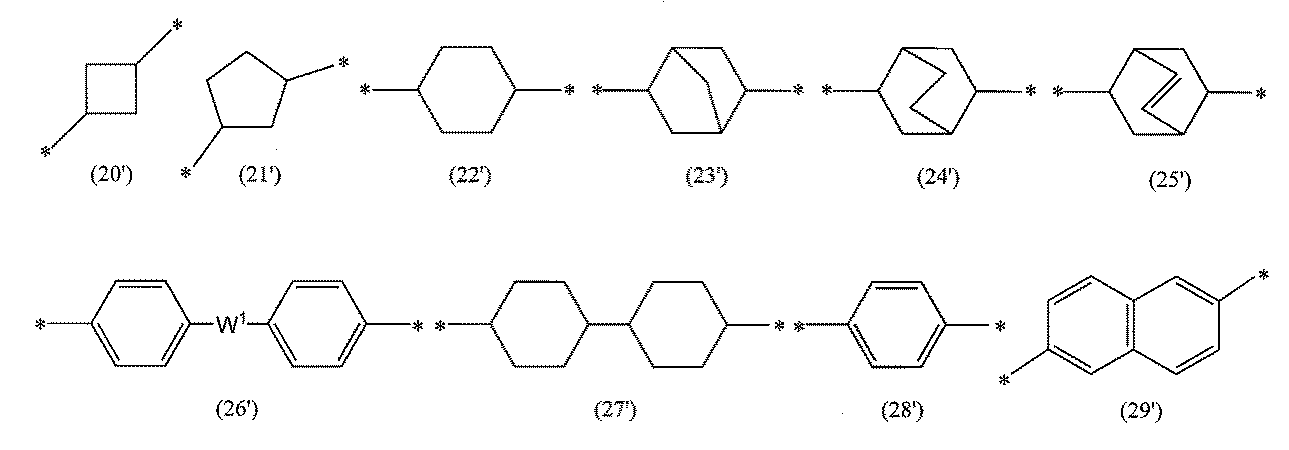
ポリイミド系樹脂が、G3が上記の式(20’)~式(29’)のいずれかで表される構成単位を有する場合、特にZが後述する式(101’)で表される構成単位を有する場合、ポリイミド系樹脂は、該構成単位に加えて、次の式(100): In the polyimide resin, when G3 has a constitutional unit represented by any one of the above formulas (20') to (29'), particularly when Z has a constitutional unit represented by the formula (101') described below, the polyimide resin may further have a constitutional unit represented by the following formula (100):
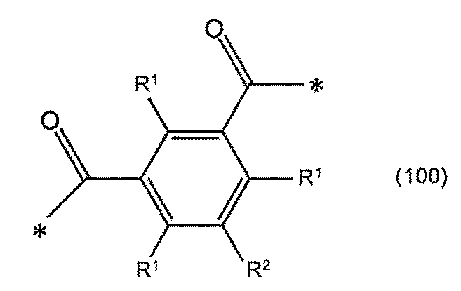
で表されるカルボン酸由来の構成単位をさらに有していてよい。この構造単位を有するポリイミド系樹脂は、透明樹脂フィルムを製造する際に使用する樹脂ワニスの流動性を高めやすいため好ましい。
The polyimide resin may further have a structural unit derived from a carboxylic acid represented by the following formula: A polyimide resin having this structural unit is preferred because it is easy to increase the fluidity of a resin varnish used in producing a transparent resin film.
R1において、炭素数1~6のアルキル基、炭素数1~6のアルコキシ基及び炭素数6~12のアリール基としては、それぞれ、後述の式(101)において例示のものが挙げられる。構成単位(100)としては、具体的には、R1及びR2がいずれも水素原子である構成単位(ジカルボン酸化合物に由来する構成単位)、R1がいずれも水素原子であり、R2が-C(=O)-*を表す構成単位(トリカルボン酸化合物に由来する構成単位)等が挙げられる。 In R1 , the alkyl group having 1 to 6 carbon atoms, the alkoxy group having 1 to 6 carbon atoms, and the aryl group having 6 to 12 carbon atoms each include those exemplified in the formula (101) described below. Specific examples of the structural unit (100) include a structural unit in which R1 and R2 are both hydrogen atoms (structural unit derived from a dicarboxylic acid compound), a structural unit in which R1 is both hydrogen atoms and R2 is -C(=O)-* (structural unit derived from a tricarboxylic acid compound), and the like.
ポリイミド系樹脂は、G3として複数種のG3を含んでよく、複数種のG3は、互いに同一であっても異なっていてもよい。特に、光学フィルムのマンドレル試験後のヘーズを低減しやすく、かつ降伏点歪及び弾性率を高めやすい観点から、G3が好ましくは式(101): The polyimide resin may contain a plurality of types of G3 as G3 , and the plurality of types of G3 may be the same or different from each other. In particular, from the viewpoint of easily reducing the haze after the mandrel test of the optical film and easily increasing the yield point strain and the elastic modulus, G3 is preferably represented by the formula (101):

R3a及びR3bは、互いに独立に、炭素数1~6のアルキル基、炭素数1~6のアルコキシ基、又は炭素数6~12のアリール基を表し、R3a及びR3bに含まれる水素原子は、互いに独立に、ハロゲン原子で置換されていてもよく、
Wは、互いに独立に、単結合、-O-、-CH2-、-CH2-CH2-、-CH(CH3)-、-C(CH3)2-、-C(CF3)2-、-SO2-、-S-、-CO-又は-N(R9)-を表し、R9は水素原子、ハロゲン原子で置換されていてもよい炭素数1~12の1価の炭化水素基を表し、
sは0~4の整数であり、
tは0~4の整数であり、
uは0~4の整数であり、
*は結合手を表す]
で表され、より好ましくは式(101’):
R 3a and R 3b each independently represent an alkyl group having 1 to 6 carbon atoms, an alkoxy group having 1 to 6 carbon atoms, or an aryl group having 6 to 12 carbon atoms, and a hydrogen atom contained in R 3a and R 3b each independently may be substituted with a halogen atom;
W each independently represents a single bond, -O-, -CH 2 -, -CH 2 -CH 2 -, -CH(CH 3 )-, -C(CH 3 ) 2 -, -C(CF 3 ) 2 -, -SO 2 -, -S-, -CO- or -N(R 9 )-, where R 9 represents a hydrogen atom or a monovalent hydrocarbon group having 1 to 12 carbon atoms which may be substituted with a halogen atom;
s is an integer from 0 to 4;
t is an integer from 0 to 4;
u is an integer from 0 to 4;
* represents a bond.
More preferably, the compound represented by formula (101'):

で表される、構成単位を少なくとも有することが好ましい。
It is preferable that the copolymer has at least a structural unit represented by the following formula:
式(101)及び式(101’)において、Wは、互いに独立に、単結合、-O-、-CH2-、-CH2-CH2-、-CH(CH3)-、-C(CH3)2-、-C(CF3)2-、-SO2-、-S-、-CO-又は-N(R9)-を表し、光学フィルムの耐屈曲性の観点から、好ましくは-O-又は-S-を表し、より好ましくは-O-を表す。 In formula (101) and formula (101'), W each independently represents a single bond, -O-, -CH 2 -, -CH 2 -CH 2 -, -CH(CH 3 )-, -C(CH 3 ) 2 -, -C(CF 3 ) 2 -, -SO 2 -, -S-, -CO- or -N(R 9 )-, and from the viewpoint of the bending resistance of the optical film, preferably represents -O- or -S-, more preferably represents -O-.
R3a及びR3bは、互いに独立に、炭素数1~6のアルキル基、炭素数1~6のアルコキシ基、又は炭素数6~12のアリール基を表す。炭素数1~6のアルキル基としては、例えばメチル基、エチル基、n-プロピル基、イソプロピル基、n-ブチル基、sec-ブチル基、tert-ブチル基、n-ペンチル基、2-メチル-ブチル基、3-メチル-ブチル基、2-エチル-プロピル基、n-ヘキシル基等が挙げられる。炭素数1~6のアルコキシ基としては、例えばメトキシ基、エトキシ基、プロピルオキシ基、イソプロピルオキシ基、ブトキシ基、イソブトキシ基、tert-ブトキシ基、ペンチルオキシ基、ヘキシルオキシ基、シクロヘキシルオキシ基等が挙げられる。炭素数6~12のアリール基としては、例えばフェニル基、トリル基、キシリル基、ナフチル基、ビフェニル基等が挙げられる。光学フィルムのマンドレル試験後のヘーズを低減しやすく、かつ降伏点歪及び弾性率を高めやすい観点から、R3a及びR3bは、互いに独立に、好ましくは炭素数1~6のアルキル基又は炭素数1~6のアルコキシ基を表し、より好ましくは炭素数1~3のアルキル基又は炭素数1~3のアルコキシ基を表す。ここで、R3a及びR3bに含まれる水素原子は、互いに独立に、ハロゲン原子で置換されていてもよい。 R 3a and R 3b each independently represent an alkyl group having 1 to 6 carbon atoms, an alkoxy group having 1 to 6 carbon atoms, or an aryl group having 6 to 12 carbon atoms. Examples of the alkyl group having 1 to 6 carbon atoms include a methyl group, an ethyl group, an n-propyl group, an isopropyl group, an n-butyl group, a sec-butyl group, a tert-butyl group, an n-pentyl group, a 2-methyl-butyl group, a 3-methyl-butyl group, a 2-ethyl-propyl group, and an n-hexyl group. Examples of the alkoxy group having 1 to 6 carbon atoms include a methoxy group, an ethoxy group, a propyloxy group, an isopropyloxy group, a butoxy group, an isobutoxy group, a tert-butoxy group, a pentyloxy group, a hexyloxy group, and a cyclohexyloxy group. Examples of the aryl group having 6 to 12 carbon atoms include a phenyl group, a tolyl group, a xylyl group, a naphthyl group, and a biphenyl group. From the viewpoint of easily reducing the haze after a mandrel test of the optical film and easily increasing the yield strain and elastic modulus, R 3a and R 3b each independently preferably represent an alkyl group having 1 to 6 carbon atoms or an alkoxy group having 1 to 6 carbon atoms, more preferably an alkyl group having 1 to 3 carbon atoms or an alkoxy group having 1 to 3 carbon atoms. Here, the hydrogen atoms contained in R 3a and R 3b each independently may be substituted with a halogen atom.
R9は水素原子、ハロゲン原子で置換されていてもよい炭素数1~12の1価の炭化水素基を表す。炭素数1~12の1価の炭化水素基としては、例えばメチル基、エチル基、n-プロピル基、イソプロピル基、n-ブチル基、sec-ブチル基、tert-ブチル基、n-ペンチル基、2-メチル-ブチル基、3-メチル-ブチル基、2-エチル-プロピル基、n-ヘキシル、n-ヘプチル基、n-オクチル基、tert-オクチル基、n-ノニル基、n-デシル基等が挙げられ、これらはハロゲン原子で置換されていてもよい。
前記ハロゲン原子としては、フッ素原子、塩素原子、臭素原子、ヨウ素原子等が挙げられる。
R9 represents a hydrogen atom or a monovalent hydrocarbon group having 1 to 12 carbon atoms which may be substituted with a halogen atom. Examples of the monovalent hydrocarbon group having 1 to 12 carbon atoms include a methyl group, an ethyl group, an n-propyl group, an isopropyl group, an n-butyl group, a sec-butyl group, a tert-butyl group, an n-pentyl group, a 2-methyl-butyl group, a 3-methyl-butyl group, a 2-ethyl-propyl group, an n-hexyl group, an n-heptyl group, an n-octyl group, a tert-octyl group, an n-nonyl group, and an n-decyl group, which may be substituted with a halogen atom.
Examples of the halogen atom include a fluorine atom, a chlorine atom, a bromine atom, and an iodine atom.
式(101)及び式(101’)中のt及びuは、互いに独立に、0~4の整数であり、好ましくは0~2の整数、より好ましくは0又は1である。 In formula (101) and formula (101'), t and u are each independently an integer from 0 to 4, preferably an integer from 0 to 2, and more preferably 0 or 1.
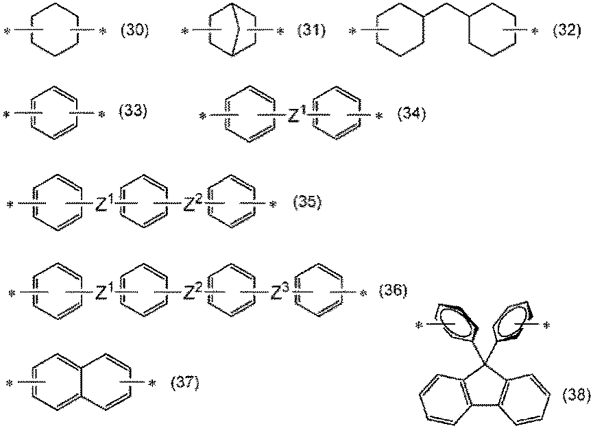
前記A、A1、A2及びA3はいずれも2価の有機基を表し、好ましくは炭素数4~40の2価の有機基を表す。前記有機基は、炭化水素基又はフッ素置換された炭素数1~8の炭化水素基で置換されていてもよく、その場合、炭化水素基及びフッ素置換された炭化水素基の炭素数は好ましくは1~8である。A、A1、A2及びA3としては、それぞれ式(30)、式(31)、式(32)、式(33)、式(34)、式(35)、式(36)、式(37)又は式(38)で表される基、これらがメチル基、フルオロ基、クロロ基又はトリフルオロメチル基の1種類以上で置換された基、及び炭素数6以下の鎖式炭化水素基が挙げられる。 The A, A 1 , A 2 and A 3 each represent a divalent organic group, preferably a divalent organic group having 4 to 40 carbon atoms. The organic group may be substituted with a hydrocarbon group or a fluorine-substituted hydrocarbon group having 1 to 8 carbon atoms, in which case the number of carbon atoms of the hydrocarbon group and the fluorine-substituted hydrocarbon group is preferably 1 to 8. Examples of A, A 1 , A 2 and A 3 include groups represented by formula (30), formula (31), formula (32), formula (33), formula (34), formula (35), formula (36), formula (37) or formula (38), groups in which these are substituted with one or more of a methyl group, a fluoro group, a chloro group or a trifluoromethyl group, and a chain hydrocarbon group having 6 or less carbon atoms.
式(30)~式(38)中の*は結合手を表し、Z1、Z2及びZ3は、互いに独立して、単結合、-O-、-CH2-、-CH2-CH2-、-CH(CH3)-、-C(CH3)2-、-C(CF3)2-、-S-、-SO2-、-CO-又は-N(R3)-を表す。ここで、R3はハロゲン原子で置換されていてもよい炭素数1~12の炭化水素基を表す。ここで、R3はハロゲン原子で置換されていてもよい炭素数1~12の炭化水素基を表す。Z1とZ2、及び、Z2とZ3は、それぞれ、各環に対して好ましくはメタ位又はパラ位に位置する。 In formulae (30) to (38), * represents a bond, and Z 1 , Z 2 and Z 3 each independently represent a single bond, -O-, -CH 2 -, -CH 2 -CH 2 -, -CH(CH 3 )-, -C(CH 3 ) 2 -, -C(CF 3 ) 2 -, -S-, -SO 2 -, -CO- or -N(R 3 )-. Here, R 3 represents a hydrocarbon group having 1 to 12 carbon atoms which may be substituted with a halogen atom. Here, R 3 represents a hydrocarbon group having 1 to 12 carbon atoms which may be substituted with a halogen atom. Z 1 and Z 2 , and Z 2 and Z 3 are preferably located at the meta position or para position relative to each ring.
本発明において、透明樹脂フィルムを形成する樹脂組成物は、ポリアミド系樹脂であってもよい。本実施形態に係るポリアミド系樹脂は、式(13)で表される繰り返し構造単位を主とする重合体である。ポリアミド系樹脂におけるG3及びA3の好ましい例及び具体例は、ポリイミド系樹脂におけるG3及びA3の好ましい例及び具体例と同じである。
前記ポリアミド系樹脂は、G3及び/又はA3が異なる2種類以上の式(13)で表される繰り返し構造単位を含んでいてもよい。
In the present invention, the resin composition forming the transparent resin film may be a polyamide resin. The polyamide resin according to this embodiment is a polymer mainly composed of a repeating structural unit represented by formula (13). Preferred examples and specific examples of G3 and A3 in the polyamide resin are the same as the preferred examples and specific examples of G3 and A3 in the polyimide resin.
The polyamide resin may contain two or more types of repeating structural units represented by formula (13) in which G3 and/or A3 are different.
ポリイミド系樹脂は、例えば、ジアミンとテトラカルボン酸化合物(テトラカルボン酸二無水物等)との重縮合により得ることができ、例えば、特開2006-199945号公報又は特開2008-163107号公報に記載されている方法にしたがって合成することができる。ポリイミドの市販品としては、三菱瓦斯化学(株)製ネオプリム(登録商標)、河村産業(株)製KPI-MX300F等が挙げられる。 Polyimide resins can be obtained, for example, by polycondensation of diamines and tetracarboxylic acid compounds (such as tetracarboxylic dianhydrides), and can be synthesized, for example, according to the method described in JP-A-2006-199945 or JP-A-2008-163107. Commercially available polyimides include Neoprim (registered trademark) manufactured by Mitsubishi Gas Chemical Co., Ltd. and KPI-MX300F manufactured by Kawamura Sangyo Co., Ltd.
ポリイミド系樹脂の合成に用いられるテトラカルボン酸化合物としては、芳香族テトラカルボン酸及びその無水物、好ましくはその二無水物等の芳香族テトラカルボン酸化合物、及び脂肪族テトラカルボン酸及びその無水物、好ましくはその二無水物等の脂肪族テトラカルボン酸化合物等が挙げられる。テトラカルボン酸化合物は、無水物の他、テトラカルボン酸クロリド化合物等のテトラカルボン酸化合物誘導体であってもよく、これらは単独で又は2種以上を組合せて使用できる。 Tetracarboxylic acid compounds used in the synthesis of polyimide resins include aromatic tetracarboxylic acids and their anhydrides, preferably their dianhydrides, and other aromatic tetracarboxylic acid compounds, and aliphatic tetracarboxylic acids and their anhydrides, preferably their dianhydrides, and other aliphatic tetracarboxylic acid compounds. In addition to anhydrides, the tetracarboxylic acid compounds may also be tetracarboxylic acid compound derivatives such as tetracarboxylic acid chloride compounds, and these can be used alone or in combination of two or more.
芳香族テトラカルボン酸二無水物の具体例としては、非縮合多環式の芳香族テトラカルボン酸二無水物、単環式の芳香族テトラカルボン酸二無水物及び縮合多環式の芳香族テトラカルボン酸二無水物が挙げられる。非縮合多環式の芳香族テトラカルボン酸二無水物としては、4,4’-オキシジフタル酸二無水物、3,3’,4,4’-ベンゾフェノンテトラカルボン酸二無水物、2,2’,3,3’-ベンゾフェノンテトラカルボン酸二無水物、3,3’,4,4’-ビフェニルテトラカルボン酸二無水物、2,2’,3,3’-ビフェニルテトラカルボン酸二無水物、3,3’,4,4’-ジフェニルスルホンテトラカルボン酸二無水物、2,2-ビス(3,4-ジカルボキシフェニル)プロパン二無水物、2,2-ビス(2,3-ジカルボキシフェニル)プロパン二無水物、2,2-ビス(3,4-ジカルボキシフェノキシフェニル)プロパン二無水物、4,4’-(ヘキサフルオロイソプロピリデン)ジフタル酸二無水物(6FDAと記載することがある)、1,2-ビス(2,3-ジカルボキシフェニル)エタン二無水物、1,1-ビス(2,3-ジカルボキシフェニル)エタン二無水物、1,2-ビス(3,4-ジカルボキシフェニル)エタン二無水物、1,1-ビス(3,4-ジカルボキシフェニル)エタン二無水物、ビス(3,4-ジカルボキシフェニル)メタン二無水物、ビス(2,3-ジカルボキシフェニル)メタン二無水物、4,4’-(p-フェニレンジオキシ)ジフタル酸二無水物、4,4’-(m-フェニレンジオキシ)ジフタル酸二無水物が挙げられる。また、単環式の芳香族テトラカルボン酸二無水物としては、1,2,4,5-ベンゼンテトラカルボン酸二無水物が、縮合多環式の芳香族テトラカルボン酸二無水物としては、2,3,6,7-ナフタレンテトラカルボン酸二無水物が挙げられる。 Specific examples of aromatic tetracarboxylic acid dianhydrides include non-condensed polycyclic aromatic tetracarboxylic acid dianhydrides, monocyclic aromatic tetracarboxylic acid dianhydrides, and condensed polycyclic aromatic tetracarboxylic acid dianhydrides. Non-condensed polycyclic aromatic tetracarboxylic acid dianhydrides include 4,4'-oxydiphthalic dianhydride, 3,3',4,4'-benzophenone tetracarboxylic acid dianhydride, 2,2',3,3'-benzophenone tetracarboxylic acid dianhydride, 3,3',4,4'-biphenyl tetracarboxylic acid dianhydride, 2,2',3,3'-biphenyl tetracarboxylic acid dianhydride, 3,3',4,4'-diphenylsulfone tetracarboxylic acid dianhydride, 2,2-bis(3,4-dicarboxyphenyl)propane dianhydride, 2,2-bis(2,3-dicarboxyphenyl)propane dianhydride, 2,2-bis(3,4-dicarboxyphenoxyphenyl)propane dianhydride, and 2,2-bis(3,4-dicarboxyphenoxyphenyl)propane dianhydride. dianhydride, 4,4'-(hexafluoroisopropylidene)diphthalic dianhydride (sometimes referred to as 6FDA), 1,2-bis(2,3-dicarboxyphenyl)ethane dianhydride, 1,1-bis(2,3-dicarboxyphenyl)ethane dianhydride, 1,2-bis(3,4-dicarboxyphenyl)ethane dianhydride, 1,1-bis(3,4-dicarboxyphenyl)ethane dianhydride, bis(3,4-dicarboxyphenyl)methane dianhydride, bis(2,3-dicarboxyphenyl)methane dianhydride, 4,4'-(p-phenylenedioxy)diphthalic dianhydride, and 4,4'-(m-phenylenedioxy)diphthalic dianhydride. In addition, an example of a monocyclic aromatic tetracarboxylic dianhydride is 1,2,4,5-benzenetetracarboxylic dianhydride, and an example of a condensed polycyclic aromatic tetracarboxylic dianhydride is 2,3,6,7-naphthalenetetracarboxylic dianhydride.
これらの中でも、好ましくは4,4’-オキシジフタル酸二無水物、3,3’,4,4’-ベンゾフェノンテトラカルボン酸二無水物、2,2’,3,3’-ベンゾフェノンテトラカルボン酸二無水物、3,3’,4,4’-ビフェニルテトラカルボン酸二無水物、2,2’,3,3’-ビフェニルテトラカルボン酸二無水物、3,3’,4,4’-ジフェニルスルホンテトラカルボン酸二無水物、2,2-ビス(3,4-ジカルボキシフェニル)プロパン二無水物、2,2-ビス(2,3-ジカルボキシフェニル)プロパン二無水物、2,2-ビス(3,4-ジカルボキシフェノキシフェニル)プロパン二無水物、4,4’-(ヘキサフルオロイソプロピリデン)ジフタル酸二無水物(6FDA)、1,2-ビス(2,3-ジカルボキシフェニル)エタン二無水物、1,1-ビス(2,3-ジカルボキシフェニル)エタン二無水物、1,2-ビス(3,4-ジカルボキシフェニル)エタン二無水物、1,1-ビス(3,4-ジカルボキシフェニル)エタン二無水物、ビス(3,4-ジカルボキシフェニル)メタン二無水物、ビス(2,3-ジカルボキシフェニル)メタン二無水物、4,4’-(p-フェニレンジオキシ)ジフタル酸二無水物及び4,4’-(m-フェニレンジオキシ)ジフタル酸二無水物が挙げられ、より好ましくは4,4’-オキシジフタル酸二無水物、3,3’,4,4’-ビフェニルテトラカルボン酸二無水物、2,2’,3,3’-ビフェニルテトラカルボン酸二無水物、4,4’-(ヘキサフルオロイソプロピリデン)ジフタル酸二無水物(6FDA)、ビス(3,4-ジカルボキシフェニル)メタン二無水物及び4,4’-(p-フェニレンジオキシ)ジフタル酸二無水物が挙げられる。これらは単独で又は2種以上を組合せて使用できる。 Among these, 4,4'-oxydiphthalic dianhydride, 3,3',4,4'-benzophenone tetracarboxylic dianhydride, 2,2',3,3'-benzophenone tetracarboxylic dianhydride, 3,3',4,4'-biphenyl tetracarboxylic dianhydride, 2,2',3,3'-biphenyl tetracarboxylic dianhydride, 3,3',4,4'-diphenylsulfone tetracarboxylic dianhydride, 2,2-bis(3,4-dicarboxyphenyl)propane dianhydride, 2,2-bis(2,3-dicarboxyphenyl)propane dianhydride, 2,2-bis(3,4-dicarboxyphenoxyphenyl)propane dianhydride, 4,4'-(hexafluoroisopropylidene)diphthalic dianhydride (6FDA), 1,2-bis(2,3-dicarboxyphenyl)ethane dianhydride, 1,1-bis(2,3-dicarboxyphenyl)ethane dianhydride, Examples of the dianhydride include 1,2-bis(3,4-dicarboxyphenyl)ethane dianhydride, 1,1-bis(3,4-dicarboxyphenyl)ethane dianhydride, bis(3,4-dicarboxyphenyl)methane dianhydride, bis(2,3-dicarboxyphenyl)methane dianhydride, 4,4'-(p-phenylenedioxy)diphthalic dianhydride, and 4,4'-(m-phenylenedioxy)diphthalic dianhydride, and more preferably 4,4'-oxydiphthalic dianhydride, 3,3',4,4'-biphenyltetracarboxylic dianhydride, 2,2',3,3'-biphenyltetracarboxylic dianhydride, 4,4'-(hexafluoroisopropylidene)diphthalic dianhydride (6FDA), bis(3,4-dicarboxyphenyl)methane dianhydride, and 4,4'-(p-phenylenedioxy)diphthalic dianhydride. These can be used alone or in combination of two or more.
脂肪族テトラカルボン酸二無水物としては、環式又は非環式の脂肪族テトラカルボン酸二無水物が挙げられる。環式脂肪族テトラカルボン酸二無水物とは、脂環式炭化水素構造を有するテトラカルボン酸二無水物であり、その具体例としては、1,2,4,5-シクロヘキサンテトラカルボン酸二無水物、1,2,3,4-シクロブタンテトラカルボン酸二無水物、1,2,3,4-シクロペンタンテトラカルボン酸二無水物等のシクロアルカンテトラカルボン酸二無水物、ビシクロ[2.2.2]オクト-7-エン-2,3,5,6-テトラカルボン酸二無水物、ジシクロヘキシル-3,3’,4,4’-テトラカルボン酸二無水物及びこれらの位置異性体が挙げられる。これらは単独で又は2種以上を組合せて使用できる。非環式脂肪族テトラカルボン酸二無水物の具体例としては、1,2,3,4-ブタンテトラカルボン酸二無水物、1,2,3,4-ペンタンテトラカルボン酸二無水物等が挙げられ、これらは単独で又は2種以上を組み合わせて使用できる。また、環式脂肪族テトラカルボン酸二無水物及び非環式脂肪族テトラカルボン酸二無水物を組合せて用いてもよい。 Examples of the aliphatic tetracarboxylic dianhydride include cyclic and non-cyclic aliphatic tetracarboxylic dianhydrides. The cyclic aliphatic tetracarboxylic dianhydride is a tetracarboxylic dianhydride having an alicyclic hydrocarbon structure, and specific examples thereof include cycloalkane tetracarboxylic dianhydrides such as 1,2,4,5-cyclohexane tetracarboxylic dianhydride, 1,2,3,4-cyclobutane tetracarboxylic dianhydride, and 1,2,3,4-cyclopentane tetracarboxylic dianhydride, bicyclo[2.2.2]oct-7-ene-2,3,5,6-tetracarboxylic dianhydride, dicyclohexyl-3,3',4,4'-tetracarboxylic dianhydride, and positional isomers thereof. These can be used alone or in combination of two or more. Specific examples of the non-cyclic aliphatic tetracarboxylic dianhydride include 1,2,3,4-butane tetracarboxylic dianhydride and 1,2,3,4-pentane tetracarboxylic dianhydride, and these can be used alone or in combination of two or more. Additionally, a combination of a cyclic aliphatic tetracarboxylic acid dianhydride and an acyclic aliphatic tetracarboxylic acid dianhydride may be used.
テトラカルボン酸化合物の中でも、透明樹脂フィルムの引張弾性率、耐屈曲性、及び光学特性を向上しやすい観点から、好ましくは前記脂環式テトラカルボン酸二無水物又は非縮合多環式の芳香族テトラカルボン酸二無水物が挙げられる。より好ましい具体例としては、3,3’,4,4’-ビフェニルテトラカルボン酸二無水物、2,2’,3,3’-ビフェニルテトラカルボン酸二無水物、2,2-ビス(3,4-ジカルボキシフェニル)プロパン二無水物、4,4’-(ヘキサフルオロイソプロピリデン)ジフタル酸二無水物(6FDA)が挙げられる。これらは単独で又は2種以上を組合せて使用できる。 Among the tetracarboxylic acid compounds, the alicyclic tetracarboxylic acid dianhydrides or non-condensed polycyclic aromatic tetracarboxylic acid dianhydrides are preferred from the viewpoint of improving the tensile modulus, bending resistance, and optical properties of the transparent resin film. More preferred examples include 3,3',4,4'-biphenyl tetracarboxylic acid dianhydride, 2,2',3,3'-biphenyl tetracarboxylic acid dianhydride, 2,2-bis(3,4-dicarboxyphenyl)propane dianhydride, and 4,4'-(hexafluoroisopropylidene)diphthalic dianhydride (6FDA). These can be used alone or in combination of two or more.
本実施形態に係るポリイミド系樹脂は、得られる透明樹脂フィルムの各種物性を損なわない範囲で、上記のポリイミド合成に用いられるテトラカルボン酸の無水物に加えて、テトラカルボン酸、トリカルボン酸化合物、ジカルボン酸化合物、それらの無水物及びそれらの誘導体をさらに反応させたものであってもよい。 The polyimide-based resin according to this embodiment may be a product obtained by further reacting tetracarboxylic acids, tricarboxylic acid compounds, dicarboxylic acid compounds, their anhydrides, and their derivatives in addition to the anhydrides of the tetracarboxylic acids used in the synthesis of the polyimide described above, to the extent that the various physical properties of the resulting transparent resin film are not impaired.
トリカルボン酸化合物としては、芳香族トリカルボン酸、脂肪族トリカルボン酸及びそれらの類縁の酸クロリド化合物、酸無水物等が挙げられ、これらは2種以上を併用してもよい。その具体例としては、1,2,4-ベンゼントリカルボン酸の無水物、1,3,5-ベンゼントリカルボン酸の酸クロリド化合物、2,3,6-ナフタレントリカルボン酸-2,3-無水物、フタル酸無水物と安息香酸とが単結合、-CH2-、-C(CH3)2-、-C(CF3)2-、-SO2-又はフェニレン基で連結された化合物が挙げられる。 Examples of the tricarboxylic acid compound include aromatic tricarboxylic acids, aliphatic tricarboxylic acids, and acid chloride compounds and acid anhydrides related thereto, which may be used in combination of two or more. Specific examples thereof include anhydride of 1,2,4-benzenetricarboxylic acid, acid chloride compound of 1,3,5-benzenetricarboxylic acid, 2,3,6-naphthalenetricarboxylic acid-2,3-anhydride, and compounds in which phthalic anhydride and benzoic acid are linked via a single bond, -CH 2 -, -C(CH 3 ) 2 -, -C(CF 3 ) 2 -, -SO 2 -, or a phenylene group.
ジカルボン酸化合物としては、芳香族ジカルボン酸、脂肪族ジカルボン酸及びそれらの類縁の酸クロリド化合物、酸無水物等が挙げられ、これらは2種以上を併用してもよい。
その具体例としては、テレフタル酸;イソフタル酸;ナフタレンジカルボン酸;4,4’-ビフェニルジカルボン酸;3,3’-ビフェニルジカルボン酸;炭素数8以下である鎖式炭化水素、のジカルボン酸化合物及び2つの安息香酸骨格が-CH2-、-S-、-C(CH3)2-、-C(CF3)2-、-O-、-N(R9)-、-C(=O)-、-SO2-又はフェニレン基で連結された化合物が挙げられる。これらは単独で又は2種以上を組合せて使用できる。ここで、R9はハロゲン原子で置換されていてもよい炭素数1~12の炭化水素基を表す。
The dicarboxylic acid compound includes aromatic dicarboxylic acids, aliphatic dicarboxylic acids, and their analogous acid chloride compounds, acid anhydrides, etc., and these may be used in combination of two or more kinds.
Specific examples thereof include dicarboxylic acid compounds of terephthalic acid, isophthalic acid, naphthalenedicarboxylic acid, 4,4'-biphenyldicarboxylic acid, 3,3'-biphenyldicarboxylic acid, chain hydrocarbons having 8 or less carbon atoms, and compounds in which two benzoic acid skeletons are linked by -CH2- , -S-, -C( CH3 ) 2- , -C ( CF3 )2-, -O-, -N( R9 )-, -C(=O)-, -SO2- or a phenylene group. These can be used alone or in combination of two or more. Here, R9 represents a hydrocarbon group having 1 to 12 carbon atoms which may be substituted with a halogen atom.
ジカルボン酸化合物としては、好ましくはテレフタル酸;イソフタル酸;4,4’-ビフェニルジカルボン酸;3,3’-ビフェニルジカルボン酸;及び2つの安息香酸骨格が-CH2-、-C(=O)-、-O-、-N(R9)-、-SO2-又はフェニレン基で連結された化合物であり、より好ましくは、テレフタル酸;4,4’-ビフェニルジカルボン酸;及び2つの安息香酸骨格が-O-、-N(R9)-、-C(=O)-又は-SO2-で連結された化合物である。これらは単独で又は2種以上を組合せて使用できる。 The dicarboxylic acid compound is preferably terephthalic acid, isophthalic acid, 4,4'-biphenyldicarboxylic acid, 3,3'-biphenyldicarboxylic acid, or a compound in which two benzoic acid skeletons are linked via -CH2- , -C(=O)-, -O-, -N( R9 )-, -SO2- or a phenylene group, and more preferably terephthalic acid, 4,4'-biphenyldicarboxylic acid, or a compound in which two benzoic acid skeletons are linked via -O-, -N( R9 )-, -C(=O)- or -SO2- . These may be used alone or in combination of two or more.
テトラカルボン酸化合物、トリカルボン酸化合物、及びジカルボン酸化合物の合計に対する、テトラカルボン酸化合物の割合は、好ましくは40モル%以上であり、より好ましくは50モル%以上であり、さらに好ましくは70モル%以上であり、よりさらに好ましくは90モル%以上であり、とりわけ好ましくは98モル%以上である。 The ratio of the tetracarboxylic acid compound to the total of the tetracarboxylic acid compound, the tricarboxylic acid compound, and the dicarboxylic acid compound is preferably 40 mol% or more, more preferably 50 mol% or more, even more preferably 70 mol% or more, even more preferably 90 mol% or more, and particularly preferably 98 mol% or more.
ポリイミド系樹脂の合成に用いられるジアミンとしては、脂肪族ジアミン、芳香族ジアミン又はそれらの混合物が挙げられる。なお、本実施形態において「芳香族ジアミン」とは、アミノ基が芳香環に直接結合しているジアミンを表し、その構造の一部に脂肪族基又はその他の置換基を含んでいてもよい。芳香環は単環でも縮合環でもよく、ベンゼン環、ナフタレン環、アントラセン環及びフルオレン環等が挙げられるが、これらに限定されるものではない。これらの中でも、好ましくはベンゼン環が挙げられる。また「脂肪族ジアミン」とは、アミノ基が脂肪族基に直接結合しているジアミンを表し、その構造の一部に芳香環やその他の置換基を含んでいてもよい。 The diamines used in the synthesis of polyimide resins include aliphatic diamines, aromatic diamines, and mixtures thereof. In this embodiment, the term "aromatic diamine" refers to a diamine in which an amino group is directly bonded to an aromatic ring, and may include an aliphatic group or other substituents as part of its structure. The aromatic ring may be a single ring or a condensed ring, and examples of the aromatic ring include a benzene ring, a naphthalene ring, an anthracene ring, and a fluorene ring, but are not limited to these. Of these, a benzene ring is preferable. The term "aliphatic diamine" refers to a diamine in which an amino group is directly bonded to an aliphatic group, and may include an aromatic ring or other substituents as part of its structure.
脂肪族ジアミンの具体例としては、ヘキサメチレンジアミン等の非環式脂肪族ジアミン及び1,3-ビス(アミノメチル)シクロヘキサン、1,4-ビス(アミノメチル)シクロヘキサン、ノルボルナンジアミン、4,4’-ジアミノジシクロヘキシルメタン等の環式脂肪族ジアミン等が挙げられ、これらは単独で又は2種以上を組合せて使用できる。 Specific examples of aliphatic diamines include acyclic aliphatic diamines such as hexamethylenediamine, and cyclic aliphatic diamines such as 1,3-bis(aminomethyl)cyclohexane, 1,4-bis(aminomethyl)cyclohexane, norbornanediamine, and 4,4'-diaminodicyclohexylmethane, which can be used alone or in combination of two or more.
芳香族ジアミンの具体例としては、p-フェニレンジアミン、m-フェニレンジアミン、2,4-トルエンジアミン、m-キシリレンジアミン、p-キシリレンジアミン、1,5-ジアミノナフタレン、2,6-ジアミノナフタレン等の、芳香環を1つ有する芳香族ジアミン、4,4’-ジアミノジフェニルメタン、4,4’-ジアミノジフェニルプロパン、4,4’-ジアミノジフェニルエーテル、3,4’-ジアミノジフェニルエーテル、3,3’-ジアミノジフェニルエーテル、4,4’-ジアミノジフェニルスルホン、3,4’-ジアミノジフェニルスルホン、3,3’-ジアミノジフェニルスルホン、1,4-ビス(4-アミノフェノキシ)ベンゼン、1,3-ビス(4-アミノフェノキシ)ベンゼン、ビス〔4-(4-アミノフェノキシ)フェニル〕スルホン、ビス〔4-(3-アミノフェノキシ)フェニル〕スルホン、2,2-ビス[4-(4-アミノフェノキシ)フェニル]プロパン、2,2-ビス[4-(3-アミノフェノキシ)フェニル]プロパン、2,2’-ジメチルベンジジン、2,2’-ビス(トリフルオロメチル)-4,4’-ジアミノジフェニル(TFMBと記載することがある)、4,4’-ビス(4-アミノフェノキシ)ビフェニル、9,9-ビス(4-アミノフェニル)フルオレン、9,9-ビス(4-アミノ-3-メチルフェニル)フルオレン、9,9-ビス(4-アミノ-3-クロロフェニル)フルオレン、9,9-ビス(4-アミノ-3-フルオロフェニル)フルオレン等の、芳香環を2つ以上有する芳香族ジアミンが挙げられる。これらは単独で又は2種以上を組合せて使用できる。 Specific examples of aromatic diamines include aromatic diamines having one aromatic ring, such as p-phenylenediamine, m-phenylenediamine, 2,4-toluenediamine, m-xylylenediamine, p-xylylenediamine, 1,5-diaminonaphthalene, and 2,6-diaminonaphthalene, 4,4'-diaminodiphenylmethane, 4,4'-diaminodiphenylpropane, 4,4'-diaminodiphenyl ether, 3,4'-diaminodiphenyl ether, 3,3'-diaminodiphenyl ether, 4,4'-diaminodiphenyl sulfone, 3,4'-diaminodiphenyl sulfone, 3,3'-diaminodiphenyl sulfone, 1,4-bis(4-aminophenoxy)benzene, 1,3-bis(4-aminophenoxy)benzene, and bis[4-(4-amino Examples of aromatic diamines having two or more aromatic rings include aromatic diamines having two or more aromatic rings, such as bis[4-(3-aminophenoxy)phenyl]sulfone, bis[4-(4-aminophenoxy)phenyl]sulfone, 2,2-bis[4-(4-aminophenoxy)phenyl]propane, 2,2-bis[4-(3-aminophenoxy)phenyl]propane, 2,2'-dimethylbenzidine, 2,2'-bis(trifluoromethyl)-4,4'-diaminodiphenyl (sometimes referred to as TFMB), 4,4'-bis(4-aminophenoxy)biphenyl, 9,9-bis(4-aminophenyl)fluorene, 9,9-bis(4-amino-3-methylphenyl)fluorene, 9,9-bis(4-amino-3-chlorophenyl)fluorene, and 9,9-bis(4-amino-3-fluorophenyl)fluorene. These can be used alone or in combination of two or more.
芳香族ジアミンとしては、好ましくは4,4’-ジアミノジフェニルメタン、4,4’-ジアミノジフェニルプロパン、4,4’-ジアミノジフェニルエーテル、3,3’-ジアミノジフェニルエーテル、4,4’-ジアミノジフェニルスルホン、3,3’-ジアミノジフェニルスルホン、1,4-ビス(4-アミノフェノキシ)ベンゼン、ビス〔4-(4-アミノフェノキシ)フェニル〕スルホン、ビス〔4-(3-アミノフェノキシ)フェニル〕スルホン、2,2-ビス[4-(4-アミノフェノキシ)フェニル]プロパン、2,2-ビス[4-(3-アミノフェノキシ)フェニル]プロパン、2,2’-ジメチルベンジジン、2,2’-ビス(トリフルオロメチル)-4,4’-ジアミノジフェニル(TFMB)、4,4’-ビス(4-アミノフェノキシ)ビフェニルが挙げられ、より好ましくは4,4’-ジアミノジフェニルメタン、4,4’-ジアミノジフェニルプロパン、4,4’-ジアミノジフェニルエーテル、4,4’-ジアミノジフェニルスルホン、1,4-ビス(4-アミノフェノキシ)ベンゼン、ビス〔4-(4-アミノフェノキシ)フェニル〕スルホン、2,2-ビス[4-(4-アミノフェノキシ)フェニル]プロパン、2,2’-ジメチルベンジジン、2,2’-ビス(トリフルオロメチル)-4,4’-ジアミノジフェニル(TFMB)、4,4’-ビス(4-アミノフェノキシ)ビフェニルが挙げられる。これらは単独で又は2種以上を組合せて使用できる。 As the aromatic diamine, preferably, 4,4'-diaminodiphenylmethane, 4,4'-diaminodiphenylpropane, 4,4'-diaminodiphenyl ether, 3,3'-diaminodiphenyl ether, 4,4'-diaminodiphenyl sulfone, 3,3'-diaminodiphenyl sulfone, 1,4-bis(4-aminophenoxy)benzene, bis[4-(4-aminophenoxy)phenyl]sulfone, bis[4-(3-aminophenoxy)phenyl]sulfone, 2,2-bis[4-(4-aminophenoxy)phenyl]propane, 2,2-bis[4-(3-aminophenoxy)phenyl]propane, 2,2'-dimethylbenzidine, 2,2'-bis(trifluoromethyl )-4,4'-diaminodiphenyl (TFMB), 4,4'-bis(4-aminophenoxy)biphenyl, more preferably 4,4'-diaminodiphenylmethane, 4,4'-diaminodiphenylpropane, 4,4'-diaminodiphenyl ether, 4,4'-diaminodiphenyl sulfone, 1,4-bis(4-aminophenoxy)benzene, bis[4-(4-aminophenoxy)phenyl]sulfone, 2,2-bis[4-(4-aminophenoxy)phenyl]propane, 2,2'-dimethylbenzidine, 2,2'-bis(trifluoromethyl)-4,4'-diaminodiphenyl (TFMB), 4,4'-bis(4-aminophenoxy)biphenyl. These can be used alone or in combination of two or more.
前記ジアミンは、フッ素系置換基を有することもできる。フッ素系置換基としては、トリフルオロメチル基等の炭素数1~5のパーフルオロアルキル基、及び、フルオロ基が挙げられる。 The diamine may also have a fluorine-based substituent. Examples of the fluorine-based substituent include a perfluoroalkyl group having 1 to 5 carbon atoms, such as a trifluoromethyl group, and a fluoro group.
上記ジアミンの中でも、高透明性及び低着色性の観点からは、好ましくはビフェニル構造を有する芳香族ジアミンからなる群から選択される1種以上が挙げられ、その具体例としては2,2’-ジメチルベンジジン、2,2’-ビス(トリフルオロメチル)-4,4’-ジアミノジフェニル(TFMB)及び4,4’-ビス(4-アミノフェノキシ)ビフェニルからなる群から選択される1種以上が挙げられる。さらに好ましくはビフェニル構造及びフッ素系置換基を有するジアミンが挙げられ、その具体例としては2,2’-ビス(トリフルオロメチル)-4,4’-ジアミノジフェニル(TFMB)が挙げられる。 Among the above diamines, from the viewpoint of high transparency and low coloration, preferably, one or more selected from the group consisting of aromatic diamines having a biphenyl structure are used, and specific examples thereof include one or more selected from the group consisting of 2,2'-dimethylbenzidine, 2,2'-bis(trifluoromethyl)-4,4'-diaminodiphenyl (TFMB), and 4,4'-bis(4-aminophenoxy)biphenyl. More preferably, diamines having a biphenyl structure and a fluorine-based substituent are used, and specific examples thereof include 2,2'-bis(trifluoromethyl)-4,4'-diaminodiphenyl (TFMB).
ポリイミド系樹脂は、ジアミンと、テトラカルボン酸化合物(酸クロリド化合物、テトラカルボン酸二無水物等のテトラカルボン酸化合物誘導体を含む)との重縮合で形成される、式(10)で表される繰り返し構造単位を含む縮合型高分子である。出発原料としては、これらに加えて、さらにトリカルボン酸化合物(酸クロリド化合物、トリカルボン酸無水物等のトリカルボン酸化合物誘導体を含む)及びジカルボン酸化合物(酸クロリド化合物等の誘導体を含む)を用いることもある。また、ポリアミド系樹脂は、ジアミンと、ジカルボン酸化合物(酸クロリド化合物等の誘導体を含む)との重縮合で形成される、式(13)で表される繰り返し構造単位を含む縮合型高分子である。 Polyimide resins are condensation polymers formed by polycondensation of diamines and tetracarboxylic acid compounds (including tetracarboxylic acid compound derivatives such as acid chloride compounds and tetracarboxylic acid dianhydrides) and contain repeating structural units represented by formula (10). In addition to these, tricarboxylic acid compounds (including tricarboxylic acid compound derivatives such as acid chloride compounds and tricarboxylic acid anhydrides) and dicarboxylic acid compounds (including derivatives such as acid chloride compounds) may also be used as starting materials. Polyamide resins are condensation polymers formed by polycondensation of diamines and dicarboxylic acid compounds (including derivatives such as acid chloride compounds) and contain repeating structural units represented by formula (13).
式(10)及び式(11)で表される繰り返し構造単位は、通常、ジアミン類及びテトラカルボン酸化合物から誘導される。式(12)で表される繰り返し構造単位は、通常、ジアミン及びトリカルボン酸化合物から誘導される。式(13)で表される繰り返し構造単位は、通常、ジアミン及びジカルボン酸化合物から誘導される。ジアミン、テトラカルボン酸化合物、トリカルボン酸化合物及びジカルボン酸化合物の具体例は、上述のとおりである。 The repeating structural units represented by formula (10) and formula (11) are usually derived from diamines and tetracarboxylic acid compounds. The repeating structural unit represented by formula (12) is usually derived from diamines and tricarboxylic acid compounds. The repeating structural unit represented by formula (13) is usually derived from diamines and dicarboxylic acid compounds. Specific examples of diamines, tetracarboxylic acid compounds, tricarboxylic acid compounds, and dicarboxylic acid compounds are as described above.
ジアミンと、テトラカルボン酸化合物等のカルボン酸化合物とのモル比は、ジアミン1.00molに対して、好ましくはテトラカルボン酸0.9mol以上1.1mol以下の範囲で適宜調節できる。高い耐折性を発現するためには得られるポリイミド系樹脂が高分子量であることが好ましいことから、ジアミン1.00molに対してテトラカルボン酸0.98mol以上1.02molであることがより好ましく、0.99mol以上1.01mol以下であることがさらに好ましい。 The molar ratio of the diamine to the carboxylic acid compound, such as a tetracarboxylic acid compound, can be appropriately adjusted within a range of preferably 0.9 mol to 1.1 mol of tetracarboxylic acid per 1.00 mol of diamine. Since it is preferable that the resulting polyimide resin has a high molecular weight in order to exhibit high folding resistance, it is more preferable that the molar ratio of the tetracarboxylic acid is 0.98 mol to 1.02 mol, and even more preferable that the molar ratio is 0.99 mol to 1.01 mol, per 1.00 mol of diamine.
また、得られる透明樹脂フィルムの黄色度を抑制する観点から、得られる高分子末端に占めるアミノ基の割合が低いことが好ましく、ジアミン1.00molに対してテトラカルボン酸化合物等のカルボン酸化合物は1.00mol以上であることが好ましい。 In addition, from the viewpoint of suppressing the yellowness of the obtained transparent resin film, it is preferable that the ratio of amino groups in the obtained polymer terminals is low, and it is preferable that the amount of carboxylic acid compound such as tetracarboxylic acid compound is 1.00 mol or more per 1.00 mol of diamine.
ジアミン及びカルボン酸化合物(たとえば、テトラカルボン酸化合物)の分子中のフッ素数を調整して、得られるポリイミド系樹脂中のフッ素量を、ポリイミド系樹脂の質量を基準として、1質量%以上、5質量%以上、10質量%以上、20質量%以上とすることができる。フッ素の割合が高いほど原料費が高くなる傾向があることから、フッ素量の上限は40質量%以下であることが好ましい。フッ素系置換基は、ジアミン又はカルボン酸化合物のいずれに存在してもよく、両方に存在してもよい。フッ素系置換基を含むことにより特にYI値が低減される場合がある。 By adjusting the number of fluorines in the molecules of the diamine and carboxylic acid compound (e.g., tetracarboxylic acid compound), the amount of fluorine in the resulting polyimide resin can be set to 1% by mass or more, 5% by mass or more, 10% by mass or more, or 20% by mass or more based on the mass of the polyimide resin. Since the raw material cost tends to increase as the fluorine content increases, the upper limit of the fluorine content is preferably 40% by mass or less. The fluorine-based substituents may be present in either the diamine or the carboxylic acid compound, or in both. The inclusion of fluorine-based substituents may particularly reduce the YI value.
本実施形態に係るポリイミド系樹脂は、異なる種類の複数の上記の繰り返し構造単位を含む共重合体でもよい。ポリイミド系樹脂の標準ポリスチレン換算の重量平均分子量は、通常100,000~800,000である。ポリイミド系樹脂の重量平均分子量が大きいと、成膜した際の屈曲性が向上することから、好ましくは200,000以上であり、より好ましくは250,000以上であり、さらに好ましくは280,000以上である。また、適度な濃度及び粘度のワニスが得られ、成膜性が向上する傾向があることから、好ましくは750,000以下であり、より好ましくは600,000以下であり、さらに好ましくは500,000以下である。異なる重量平均分子量のポリイミド系樹脂を2種類以上組合せて用いてもよい。さらに物性を損なわない範囲で、他の高分子材料を混合してもよい。 The polyimide resin according to the present embodiment may be a copolymer containing a plurality of different types of the repeating structural units described above. The weight average molecular weight of the polyimide resin in terms of standard polystyrene is usually 100,000 to 800,000. Since a large weight average molecular weight of the polyimide resin improves the flexibility when formed into a film, it is preferably 200,000 or more, more preferably 250,000 or more, and even more preferably 280,000 or more. In addition, since a varnish with a suitable concentration and viscosity is obtained and film formability tends to be improved, it is preferably 750,000 or less, more preferably 600,000 or less, and even more preferably 500,000 or less. Two or more types of polyimide resins having different weight average molecular weights may be used in combination. Furthermore, other polymer materials may be mixed within a range that does not impair physical properties.
ポリイミド系樹脂及びポリアミド系樹脂は、含フッ素置換基を含むことにより、フィルム化した際の引張弾性率が向上するとともに、YI値が低減される傾向を示す。フィルムの引張弾性率が高いと、キズ及びシワ等の発生が抑制される傾向がある。フィルムの透明性の観点から、ポリイミド系樹脂及びポリアミド系樹脂は、含フッ素置換基を有することが好ましい。含フッ素置換基の具体例としては、フルオロ基及びトリフルオロメチル基が挙げられる。 When polyimide-based resins and polyamide-based resins contain fluorine-containing substituents, the tensile modulus of elasticity is improved when the resin is made into a film, and the YI value tends to be reduced. When the tensile modulus of elasticity of a film is high, the occurrence of scratches and wrinkles tends to be suppressed. From the viewpoint of film transparency, it is preferable that polyimide-based resins and polyamide-based resins have a fluorine-containing substituent. Specific examples of fluorine-containing substituents include a fluoro group and a trifluoromethyl group.
ポリイミド系樹脂及びポリイミド系樹脂とポリアミド系樹脂との混合物におけるフッ素原子の含有量は、それぞれ、ポリイミド系樹脂の質量又はポリイミド系樹脂の質量とポリアミド系樹脂の質量との合計を基準として、好ましくは1質量%以上40質量%以下であり、さらに好ましくは5質量%以上40質量%以下である。フッ素原子の含有量が上記の範囲であると、フィルム化した際のYI値をより低減し、透明性をより向上することができる傾向がある。 The content of fluorine atoms in the polyimide resin and the mixture of polyimide resin and polyamide resin is preferably 1% by mass or more and 40% by mass or less, more preferably 5% by mass or more and 40% by mass or less, based on the mass of the polyimide resin or the sum of the mass of the polyimide resin and the mass of the polyamide resin, respectively. When the content of fluorine atoms is within the above range, there is a tendency that the YI value when made into a film can be further reduced and the transparency can be further improved.
本発明において、透明樹脂フィルムを構成する樹脂組成物におけるポリイミド系樹脂及び/又はポリアミド系樹脂の含有量は、樹脂組成物の固形分に対して、好ましくは40質量%以上、より好ましくは50質量%以上、さらに好ましくは60質量%以上、さらにより好ましくは70質量%以上であり、100質量%であってもよい。ポリイミド系樹脂及び/又はポリアミド系樹脂の含有量が上記下限値以上であると、透明樹脂フィルムの屈曲性が良好である。なお、固形分とは、樹脂組成物から溶媒を除いた成分の合計量のことをいう。 In the present invention, the content of polyimide-based resin and/or polyamide-based resin in the resin composition constituting the transparent resin film is preferably 40% by mass or more, more preferably 50% by mass or more, even more preferably 60% by mass or more, and even more preferably 70% by mass or more, based on the solid content of the resin composition, and may be 100% by mass. When the content of polyimide-based resin and/or polyamide-based resin is equal to or more than the above lower limit, the flexibility of the transparent resin film is good. The solid content refers to the total amount of components excluding the solvent from the resin composition.
ポリイミド樹脂及びポリアミドイミド樹脂のイミド化率は、好ましくは90%以上、より好ましくは93%以上、さらに好ましくは96%以上である。光学フィルム及び/又は光学積層体の光学的均質性を高めやすい観点から、イミド化率が上記の下限以上であることが好ましい。また、イミド化率の上限は100%以下である。イミド化率は、ポリイミド樹脂又はポリアミドイミド樹脂中のテトラカルボン酸化合物に由来する構成単位のモル量の2倍の値に対する、ポリイミド樹脂及びポリアミドイミド樹脂中のイミド結合のモル量の割合を示す。なお、ポリイミド樹脂及びポリアミドイミド樹脂がトリカルボン酸化合物を含む場合には、ポリイミド樹脂及びポリアミドイミド樹脂中のテトラカルボン酸化合物に由来する構成単位のモル量の2倍の値と、トリカルボン酸化合物に由来する構成単位のモル量との合計に対する、ポリイミド樹脂及びポリアミドイミド樹脂中のイミド結合のモル量の割合を示す。また、イミド化率は、IR法、NMR法等により求めることができ、例えば、NMR法においては、実施例に記載の方法により測定できる。 The imidization rate of the polyimide resin and the polyamideimide resin is preferably 90% or more, more preferably 93% or more, and even more preferably 96% or more. From the viewpoint of easily increasing the optical homogeneity of the optical film and/or the optical laminate, it is preferable that the imidization rate is equal to or higher than the above lower limit. The upper limit of the imidization rate is 100% or less. The imidization rate indicates the ratio of the molar amount of imide bonds in the polyimide resin and the polyamideimide resin to twice the molar amount of the constituent units derived from the tetracarboxylic acid compound in the polyimide resin or the polyamideimide resin. In addition, when the polyimide resin and the polyamideimide resin contain a tricarboxylic acid compound, it indicates the ratio of the molar amount of imide bonds in the polyimide resin and the polyamideimide resin to the sum of twice the molar amount of the constituent units derived from the tetracarboxylic acid compound in the polyimide resin and the polyamideimide resin and the molar amount of the constituent units derived from the tricarboxylic acid compound. In addition, the imidization rate can be determined by the IR method, the NMR method, etc., and for example, in the NMR method, it can be measured by the method described in the Examples.
本発明において、透明樹脂フィルムを形成する樹脂組成物は、上記ポリイミド系樹脂及び/又はポリアミド系樹脂に加えて、無機粒子等の無機材料をさらに含有していてもよい。無機材料として、シリカ粒子、チタン粒子、水酸化アルミニウム、ジルコニア粒子、チタン酸バリウム粒子等の無機粒子、また、オルトケイ酸テトラエチル等の4級アルコキシシラン等のケイ素化合物が挙げられる。ワニスの安定性、無機材料の分散性の観点から、好ましくはシリカ粒子、水酸化アルミニウム、ジルコニア粒子、さらに好ましくはシリカ粒子である。 In the present invention, the resin composition forming the transparent resin film may further contain inorganic materials such as inorganic particles in addition to the polyimide-based resin and/or polyamide-based resin. Examples of inorganic materials include inorganic particles such as silica particles, titanium particles, aluminum hydroxide, zirconia particles, and barium titanate particles, as well as silicon compounds such as quaternary alkoxysilanes such as tetraethyl orthosilicate. From the viewpoints of the stability of the varnish and the dispersibility of the inorganic materials, silica particles, aluminum hydroxide, and zirconia particles are preferred, and silica particles are more preferred.
無機材料粒子の平均一次粒子径は、好ましくは10~100nm、より好ましくは10~90nm、さらに好ましくは10~50nm、さらにより好ましくは10~30nmである。シリカ粒子の平均一次粒子径が100nm以下であると透明性が向上する傾向がある。シリカ粒子の平均一次粒子径が10nm以上であると、シリカ粒子の凝集力が弱まるために取り扱い易くなる傾向がある。 The average primary particle size of the inorganic material particles is preferably 10 to 100 nm, more preferably 10 to 90 nm, even more preferably 10 to 50 nm, and even more preferably 10 to 30 nm. If the average primary particle size of the silica particles is 100 nm or less, transparency tends to be improved. If the average primary particle size of the silica particles is 10 nm or more, the cohesive force of the silica particles is weakened, and they tend to be easier to handle.
本発明においてシリカ粒子は、溶媒等にシリカ粒子を分散させたシリカゾルであっても、気相法で製造したシリカ微粒子粉末を用いてもよいが、ハンドリングが容易であることから液相法で製造したシリカゾルであることが好ましい。 In the present invention, the silica particles may be a silica sol in which silica particles are dispersed in a solvent or a silica fine powder produced by a gas phase method, but it is preferable to use a silica sol produced by a liquid phase method because it is easy to handle.
透明樹脂フィルム中のシリカ粒子の平均一次粒子径は、透過型電子顕微鏡(TEM)による観察で求めることができる。透明樹脂フィルムを形成する前のシリカ粒子の粒度分布は、市販のレーザー回折式粒度分布計により求めることができる。 The average primary particle size of the silica particles in the transparent resin film can be determined by observation with a transmission electron microscope (TEM). The particle size distribution of the silica particles before forming the transparent resin film can be determined with a commercially available laser diffraction particle size distribution analyzer.
本発明において、樹脂組成物が無機材料を含有する場合、その含有量は、樹脂組成物の固形分に対して、好ましくは0.001質量%以上90質量%以下であり、より好ましくは0.001質量%以上60質量%以下であり、さらに好ましくは0.001質量%以上40質量%以下である。樹脂組成物における無機材料の含有量が上記の範囲内であると、透明樹脂フィルムの透明性及び機械的強度を両立させやすい傾向がある。なお、固形分とは、樹脂組成物から溶剤を除いた成分の合計量のことをいう。 In the present invention, when the resin composition contains an inorganic material, the content thereof is preferably 0.001% by mass or more and 90% by mass or less, more preferably 0.001% by mass or more and 60% by mass or less, and even more preferably 0.001% by mass or more and 40% by mass or less, based on the solid content of the resin composition. When the content of the inorganic material in the resin composition is within the above range, it tends to be easy to achieve both transparency and mechanical strength of the transparent resin film. The solid content refers to the total amount of components excluding the solvent from the resin composition.
透明樹脂フィルムを構成する樹脂組成物は、以上説明した成分に加えて、他の成分をさらに含有していてもよい。他の成分としては、例えば、酸化防止剤、離型剤、光安定剤、ブルーイング剤、難燃剤、滑剤及びレベリング剤が挙げられる。 The resin composition constituting the transparent resin film may further contain other components in addition to the components described above. Examples of other components include antioxidants, release agents, light stabilizers, bluing agents, flame retardants, lubricants, and leveling agents.
本発明において樹脂組成物がポリイミド系樹脂等の樹脂成分及び無機材料以外の他の成分を含む場合、その他の成分の含有量は、透明樹脂フィルムの総質量に対して好ましくは0.001%以上20質量%以下であり、より好ましくは0.001%以上10質量%以下である。 In the present invention, when the resin composition contains other components other than the resin component such as a polyimide resin and the inorganic material, the content of the other components is preferably 0.001% or more and 20% or less by mass, more preferably 0.001% or more and 10% or less by mass, based on the total mass of the transparent resin film.
本発明において透明樹脂フィルムは、例えば、前記テトラカルボン酸化合物、前記ジアミン及び前記のその他の原料から選択して反応させて得られる、ポリイミド系樹脂及び/又はポリアミド系樹脂の反応液、必要に応じて無機材料及びその他の成分を含む樹脂組成物に、溶媒を加えて混合及び撹拌することにより調製される樹脂ワニスから製造することができる。前記樹脂組成物において、ポリイミド系樹脂等の反応液に変えて、購入したポリイミド系樹脂等の溶液、購入した固体のポリイミド系樹脂等の溶液を用いてもよい。 In the present invention, the transparent resin film can be produced from a resin varnish prepared by adding a solvent to a reaction liquid of a polyimide resin and/or a polyamide resin obtained by reacting a selected one of the tetracarboxylic acid compound, the diamine, and the other raw materials, and mixing and stirring the reaction liquid and a resin composition containing an inorganic material and other components as necessary. In the resin composition, a solution of a purchased polyimide resin or a solution of a purchased solid polyimide resin may be used instead of the reaction liquid of the polyimide resin or the like.
樹脂ワニスを調製するために用い得る溶媒としては、ポリイミド系樹脂等の樹脂成分を溶解又は分散させ得るものを適宜選択することができる。樹脂成分の溶解性、塗布性及び乾燥性等の観点からは、溶媒の沸点は、好ましくは120~300℃、より好ましくは120~270℃、さらに好ましくは120~250℃、特に好ましくは120~230℃である。かかる溶媒としては、具体的に例えば、N,N-ジメチルホルムアミド、N,N-ジメチルアセトアミド、N-メチルピロリドン等のアミド系溶媒;γ-ブチロラクトン、γ-バレロラクトン等のラクトン系溶媒;シクロヘキサノン、シクロペンタノン、メチルエチルケトン等のケトン系溶媒;酢酸ブチル、酢酸アミル等の酢酸エステル系溶媒;ジメチルスルホン、ジメチルスルホキシド、スルホラン等の含硫黄系溶媒、エチレンカーボネート、プロピレンカーボネート等のカーボネート系溶媒等が挙げられる。中でも、ポリイミド系樹脂及びポリアミド系樹脂に対する溶解性に優れることから、N,N-ジメチルアセトアミド(沸点:165℃)、γ-ブチロラクトン(沸点:204℃)、N-メチルピロリドン(沸点:202℃)、酢酸ブチル(沸点:126℃)、シクロペンタノン(沸点:131℃)及び酢酸アミル(沸点:149℃)からなる群から選択される溶媒が好ましい。溶媒として、1種を単独で用いてもよく、2種以上を組合せて用いてもよい。なお、2種以上の溶媒を用いる場合には、用いる溶媒の中で最も沸点の高い溶媒の沸点が上記範囲に入るよう溶媒の種類を選択することが好ましい。 As a solvent that can be used to prepare a resin varnish, one that can dissolve or disperse resin components such as polyimide resins can be appropriately selected. From the viewpoint of the solubility, coatability, and drying property of the resin components, the boiling point of the solvent is preferably 120 to 300°C, more preferably 120 to 270°C, even more preferably 120 to 250°C, and particularly preferably 120 to 230°C. Specific examples of such solvents include amide-based solvents such as N,N-dimethylformamide, N,N-dimethylacetamide, and N-methylpyrrolidone; lactone-based solvents such as γ-butyrolactone and γ-valerolactone; ketone-based solvents such as cyclohexanone, cyclopentanone, and methyl ethyl ketone; acetate-based solvents such as butyl acetate and amyl acetate; sulfur-containing solvents such as dimethyl sulfone, dimethyl sulfoxide, and sulfolane; carbonate-based solvents such as ethylene carbonate and propylene carbonate, and the like. Among these, a solvent selected from the group consisting of N,N-dimethylacetamide (boiling point: 165°C), γ-butyrolactone (boiling point: 204°C), N-methylpyrrolidone (boiling point: 202°C), butyl acetate (boiling point: 126°C), cyclopentanone (boiling point: 131°C) and amyl acetate (boiling point: 149°C) is preferred because of its excellent solubility in polyimide resins and polyamide resins. As the solvent, one type may be used alone, or two or more types may be used in combination. When two or more types of solvents are used, it is preferable to select the type of solvent so that the boiling point of the solvent with the highest boiling point falls within the above range.
溶媒の量は、樹脂ワニスの取り扱いが可能な粘度になるように選択すればよく、特に制限はないが、例えば樹脂ワニス全量に対して、好ましくは50~95質量%、より好ましくは70~95質量%、さらに好ましくは80~95質量%である。 The amount of solvent is not particularly limited as long as it is selected so that the viscosity of the resin varnish is easy to handle, but it is preferably 50 to 95% by mass, more preferably 70 to 95% by mass, and even more preferably 80 to 95% by mass, based on the total amount of the resin varnish.
本発明の透明樹脂フィルムは、上記樹脂ワニスを支持体上に塗工して、プレ乾燥することにより、得られる。透明樹脂フィルムは、支持体上に剥離可能に積層される。剥離可能であるということは、フィルムとして形状を維持でき、かつ、破断することなく支持体から剥離できることを意味する。具体的には、プレ乾燥にて適当量の溶媒が残留するように乾燥することを意味する。ここで残留溶媒量が多すぎると、フィルムとしての形状が維持できなくなり、また、残留溶媒量が少なすぎると支持体との密着性が高くなりすぎ剥離時に破断する。適切な残留溶媒量は、透明樹脂フィルムの樹脂組成物、溶媒、支持体の種類に依存して変わるものであり、適宜調整する必要がある。ただし、通常、透明樹脂フィルム中の溶媒の含有量は、透明樹脂フィルムの総質量に対して0.1質量%以上である。透明樹脂フィルム中の溶媒含有量の上限値は、フィルムとして形状を維持できる範囲であれば特に限定されるものではないが、通常、透明樹脂フィルムの総質量に対して50質量%以下である。 The transparent resin film of the present invention is obtained by applying the above-mentioned resin varnish onto a support and pre-drying it. The transparent resin film is peelably laminated onto the support. Peelable means that the film can maintain its shape and can be peeled off from the support without breaking. Specifically, pre-drying means drying so that an appropriate amount of solvent remains. If the amount of residual solvent is too large, the film cannot maintain its shape, and if the amount of residual solvent is too small, the film will not adhere to the support and will break when peeled off. The appropriate amount of residual solvent varies depending on the type of resin composition, solvent, and support of the transparent resin film, and needs to be adjusted appropriately. However, the content of the solvent in the transparent resin film is usually 0.1% by mass or more relative to the total mass of the transparent resin film. The upper limit of the solvent content in the transparent resin film is not particularly limited as long as it is within the range in which the film can maintain its shape, but is usually 50% by mass or less relative to the total mass of the transparent resin film.
樹脂製の板状体の厚さは、好ましくは10~200μmである。樹脂製の板状体の厚さをこの範囲に調節することで、耐衝撃性を維持しながら耐屈曲性を向上させやすくなる。
樹脂製の板状体の厚さは、より好ましくは20~100μmであり、さらに好ましくは30~80μmである。
The thickness of the resin plate is preferably 10 to 200 μm. By adjusting the thickness of the resin plate to fall within this range, it becomes easier to improve bending resistance while maintaining impact resistance.
The thickness of the resin plate is more preferably 20 to 100 μm, and further preferably 30 to 80 μm.
上記透明樹脂フィルムの黄色度(YI値)は、好ましくは3.0以下、より好ましくは2.7以下、さらに好ましくは2.5以下、特に好ましくは2.0以下である。光学積層体の黄色度が上記の上限以下であると透明性を向上させやすく、例えば表示装置の前面板に使用した場合に視認性を高めやすい。黄色度は、通常-5以上、好ましくは-2以上、より好ましくは0以上、さらに好ましくは0.3以上、さらに好ましくは0.5以上、特に好ましくは0.7以上である。黄色度(YI)は、JIS K 7373:2006に準拠して、紫外可視近赤外分光光度計を用いて300~800nmの光に対する透過率測定を行い、3刺激値(X、Y、Z)を求め、YI=100×(1.2769X-1.0592Z)/Yの式に基づいて算出できる。 The yellowness index (YI value) of the transparent resin film is preferably 3.0 or less, more preferably 2.7 or less, even more preferably 2.5 or less, and particularly preferably 2.0 or less. If the yellowness index of the optical laminate is equal to or less than the upper limit, transparency is easily improved, and for example, visibility is easily improved when the optical laminate is used as a front panel of a display device. The yellowness index is usually -5 or more, preferably -2 or more, more preferably 0 or more, even more preferably 0.3 or more, even more preferably 0.5 or more, and particularly preferably 0.7 or more. The yellowness index (YI) can be calculated based on the formula YI = 100 x (1.2769X - 1.0592Z) / Y by measuring the transmittance of light of 300 to 800 nm using an ultraviolet-visible-near infrared spectrophotometer in accordance with JIS K 7373:2006, determining the tristimulus values (X, Y, Z).
透明樹脂フィルムの全光線透過率は、好ましくは80%以上、より好ましくは85%以上、さらに好ましくは89%、ことさらに好ましくは90%以上である。全光線透過率が上記の下限以上であると、前面板を画像表示装置に組み込んだ際に視認性を高めやすい。
全光線透過率の上限は、通常100%以下である。なお、全光線透過率は、例えばJIS K 7361-1:1997に準拠してヘーズコンピュータを用いて測定できる。
The total light transmittance of the transparent resin film is preferably 80% or more, more preferably 85% or more, even more preferably 89%, and particularly preferably 90% or more. If the total light transmittance is equal to or more than the above lower limit, visibility is easily improved when the front panel is incorporated into an image display device.
The upper limit of the total light transmittance is usually 100% or less. The total light transmittance can be measured, for example, using a haze computer in accordance with JIS K 7361-1:1997.
透明樹脂フィルムのヘーズは、好ましくは3.0%以下、より好ましくは2.0%以下、さらに好ましくは1.0%以下、さらにより好ましくは0.5%以下、特に好ましくは0.3%以下である。透明樹脂フィルムのヘーズが上記の上限以下であると透明性が良好となり、例えば画像表示装置の前面板に使用した場合に、画像の視認性を高めやすい。
またヘーズの下限は通常0.01%以上である。なお、ヘーズは、JIS K 7136:2000に準拠してヘーズコンピュータを用いて測定できる。
The haze of the transparent resin film is preferably 3.0% or less, more preferably 2.0% or less, even more preferably 1.0% or less, still more preferably 0.5% or less, and particularly preferably 0.3% or less. When the haze of the transparent resin film is equal to or less than the above upper limit, the transparency is good, and when the film is used as a front panel of an image display device, for example, the visibility of the image is easily improved.
The lower limit of the haze is usually 0.01% or more. The haze can be measured using a haze computer in accordance with JIS K 7136:2000.
前面板1は、基材フィルムの少なくとも一方の面にハードコート層を設けて硬度をより向上させたフィルムであってよい。基材フィルムとしては、上記樹脂からできたフィルムを用いることができる。ハードコート層は、基材フィルムの一方の面に形成されていてもよいし、両方の面に形成されていてもよい。ハードコート層を設けることにより、硬度及びスクラッチ性を向上させた樹脂フィルムとすることができる。ハードコート層は、例えば紫外線硬化型樹脂の硬化層である。紫外線硬化型樹脂としては、例えば、アクリル系樹脂、シリコーン系樹脂、ポリエステル系樹脂、ウレタン系樹脂、アミド系樹脂、エポキシ系樹脂等が挙げられる。ハードコート層は、強度を向上させるために、添加剤を含んでいてもよい。添加剤は限定されることはなく、無機系微粒子、有機系微粒子、又はこれらの混合物が挙げられる。
The
光学積層体が表示装置に用いられる場合、前面板1は、表示装置におけるウィンドウフィルムとしての機能を有していてよい。前面板1は、ブルーライトカット機能、視野角調整機能等を有するものであってもよい。前面板1は、表示装置の最表面を構成する層であることができる。
When the optical laminate is used in a display device, the
前面板1の厚さは、好ましくは20~220μmである。前面板1の厚さをこの範囲に調節することで、耐衝撃性を維持しながら耐屈曲性を向上させやすくなる上、硬度を付与することもできる。前面板1の厚さは、より好ましくは35~110μmであり、さらに好ましくは40~70μmである。
The thickness of the
前面板1の引張弾性率は、好ましくは3GPa以上であり、より好ましくは4GPa以上であり、さらに好ましくは5GPa以上である。前面板1の引張弾性率は、好ましくは10GPa以下であり、より好ましくは9GPa以下である。引張弾性率が上記の下限値以上であると、外部から衝撃を受けた場合、前面板に凹み等の欠陥が生じにくくなると共に、前面板の強度を高めやすい。また、引張弾性率が上記の上限値以下であると、前面板の耐屈曲性を向上させやすい。引張弾性率は、MD(Machine Direction、フィルムの成形方向)、またはTD(Transverse Direction、MDに垂直方向)の少なくとも一方で上記範囲を満たせばよく、両方で上記範囲を満たすことが好ましい。
The tensile modulus of the
[粘着剤層]
粘着剤層は、光学積層体を構成する非粘着性層の間、又は光学積層体を構成する非粘着性層と表示ユニット等の被着物との間に位置する。粘着剤層は、その両側に存在する部材同士を結合する層である。ある一形態においては、図1を参照して、光学積層体10は第1粘着剤層2と、第2粘着剤層4とを、有する。第1粘着剤層2は、前面板1と後述の耐衝撃層3との間に位置し、両者を結合する。第2粘着剤層は、耐衝撃層3の内部表面上に位置し、耐衝撃層と被着物を結合する。被着物としては、例えば、表示ユニットの偏光板、円偏光板、タッチセンサ等が挙げられる。各粘着剤層は、同じ材料からなるものであっても、異なる材料からなるものであってもよい。
[Adhesive layer]
The adhesive layer is located between the non-adhesive layers constituting the optical laminate, or between the non-adhesive layers constituting the optical laminate and an adherend such as a display unit. The adhesive layer is a layer that bonds members present on both sides of the adhesive layer. In one embodiment, referring to FIG. 1, the
粘着剤層は、(メタ)アクリル系、ゴム系、ウレタン系、エステル系、シリコーン系、ポリビニルエーテル系のような樹脂を主成分とする粘着剤組成物で構成することができる。中でも、透明性、耐候性、耐熱性等に優れる(メタ)アクリル系樹脂をベースポリマーとする粘着剤組成物が好ましい。粘着剤組成物は、活性エネルギー線硬化型、熱硬化型であってもよい。 The adhesive layer can be composed of an adhesive composition mainly composed of a resin such as a (meth)acrylic, rubber, urethane, ester, silicone, or polyvinyl ether resin. Among them, an adhesive composition having a (meth)acrylic resin as a base polymer, which has excellent transparency, weather resistance, heat resistance, etc., is preferred. The adhesive composition may be of the active energy ray curing type or the heat curing type.
粘着剤組成物に用いられる(メタ)アクリル系樹脂(ベースポリマー)としては、例えば、(メタ)アクリル酸ブチル、(メタ)アクリル酸エチル、(メタ)アクリル酸イソオクチル、(メタ)アクリル酸2-エチルヘキシルのような(メタ)アクリル酸エステルの1種又は2種以上をモノマーとする重合体又は共重合体が好ましく用いられる。ベースポリマーには、極性モノマーを共重合させることが好ましい。極性モノマーとしては、例えば、(メタ)アクリル酸、(メタ)アクリル酸2-ヒドロキシプロピル、(メタ)アクリル酸ヒドロキシエチル、(メタ)アクリルアミド、N,N-ジメチルアミノエチル(メタ)アクリレート、グリシジル(メタ)アクリレートのような、カルボキシル基、水酸基、アミド基、アミノ基、エポキシ基等を有するモノマーが挙げられる。 As the (meth)acrylic resin (base polymer) used in the adhesive composition, for example, a polymer or copolymer containing one or more (meth)acrylic acid esters as monomers, such as butyl (meth)acrylate, ethyl (meth)acrylate, isooctyl (meth)acrylate, and 2-ethylhexyl (meth)acrylate, is preferably used. A polar monomer is preferably copolymerized into the base polymer. Examples of polar monomers include monomers having a carboxyl group, a hydroxyl group, an amide group, an amino group, an epoxy group, etc., such as (meth)acrylic acid, 2-hydroxypropyl (meth)acrylate, hydroxyethyl (meth)acrylate, (meth)acrylamide, N,N-dimethylaminoethyl (meth)acrylate, and glycidyl (meth)acrylate.
粘着剤組成物は、上記ベースポリマーのみを含むものであってもよいが、通常は架橋剤をさらに含む。架橋剤としては、2価以上の金属イオンであって、カルボキシル基との間でカルボン酸金属塩を形成するもの;ポリアミン化合物であって、カルボキシル基との間でアミド結合を形成するもの;ポリエポキシ化合物やポリオールであって、カルボキシル基との間でエステル結合を形成するもの;ポリイソシアネート化合物であって、カルボキシル基との間でアミド結合を形成するものが挙げられ、好ましくはポリイソシアネート化合物が挙げられる。 The adhesive composition may contain only the base polymer, but usually further contains a crosslinking agent. Examples of crosslinking agents include divalent or higher metal ions that form metal carboxylates with carboxyl groups; polyamine compounds that form amide bonds with carboxyl groups; polyepoxy compounds or polyols that form ester bonds with carboxyl groups; and polyisocyanate compounds that form amide bonds with carboxyl groups, with polyisocyanate compounds being preferred.
活性エネルギー線硬化型粘着剤組成物とは、紫外線や電子線のような活性エネルギー線の照射を受けて硬化する性質を有しており、活性エネルギー線照射前においても粘着性を有してフィルム等の被着体に密着させることができ、活性エネルギー線の照射により硬化して密着力の調整ができる性質を有する粘着剤組成物である。活性エネルギー線硬化型粘着剤組成物は、紫外線硬化型であることが好ましい。活性エネルギー線硬化型粘着剤組成物は、ベースポリマー、架橋剤に加えて、活性エネルギー線重合性化合物をさらに含む。
さらに必要に応じて、光重合開始剤や光増感剤等を含有させることもある。
The active energy ray curable pressure-sensitive adhesive composition has a property of being cured by irradiation with active energy rays such as ultraviolet rays and electron beams, and has adhesiveness even before irradiation with active energy rays, can be adhered to an adherend such as a film, and can be cured by irradiation with active energy rays to adjust the adhesive strength. The active energy ray curable pressure-sensitive adhesive composition is preferably an ultraviolet ray curable type. The active energy ray curable pressure-sensitive adhesive composition further contains an active energy ray polymerizable compound in addition to a base polymer and a crosslinking agent.
If necessary, a photopolymerization initiator, a photosensitizer, etc. may also be contained.
粘着剤組成物は、光散乱性を付与するための微粒子、ビーズ(樹脂ビーズ、ガラスビーズ等)、ガラス繊維、ベースポリマー以外の樹脂、粘着性付与剤、充填剤(金属粉やその他の無機粉末等)、酸化防止剤、紫外線吸収剤、染料、顔料、着色剤、消泡剤、腐食防止剤、光重合開始剤等の添加剤を含んでいてよい。 The adhesive composition may contain additives such as fine particles for imparting light scattering properties, beads (resin beads, glass beads, etc.), glass fibers, resins other than the base polymer, tackifiers, fillers (metal powders and other inorganic powders, etc.), antioxidants, UV absorbers, dyes, pigments, colorants, defoamers, corrosion inhibitors, and photopolymerization initiators.
上記粘着剤組成物の有機溶剤希釈液を基材上に塗布し、乾燥させることにより形成することができる。活性エネルギー線硬化型粘着剤組成物を用いた場合は、形成された粘着剤層に、活性エネルギー線を照射することにより所望の硬化度を有する硬化物とすることができる。 The adhesive layer can be formed by applying an organic solvent diluted solution of the adhesive composition to a substrate and drying it. When an active energy ray curable adhesive composition is used, the formed adhesive layer can be irradiated with active energy rays to form a cured product having the desired degree of cure.
粘着剤層は粘弾性を有し、光学積層体に加えられる衝撃を緩和する機能を有する。本発明の光学積層体では、粘着剤層の特性を適宜調節することで、前面に加えられる衝撃に対する光学積層体の耐衝撃性を向上させる。つまり、光学積層体の表面に衝撃が加えられた場合でも、タッチセンサ層や光学積層体がカバーする表示パネルの配線及び素子等が破損し難くなる。 The adhesive layer has viscoelasticity and functions to absorb impacts applied to the optical laminate. In the optical laminate of the present invention, the properties of the adhesive layer are appropriately adjusted to improve the impact resistance of the optical laminate against impacts applied to the front surface. In other words, even if an impact is applied to the surface of the optical laminate, the touch sensor layer and the wiring and elements of the display panel covered by the optical laminate are less likely to be damaged.
発明者の検討により、粘着剤層の弾性、厚さ及び位置が光学積層体の耐衝撃性に関係することが明らかになった。粘着剤層による衝撃緩和効果は、粘着剤層の貯蔵弾性率が低いほど大きくなる。また、粘着剤層による衝撃緩和効果は、粘着剤層が厚いほど大きくなる。そして、粘着剤層による上記衝撃緩和効果は、粘着剤層の位置が表示パネルに近いほど有効性が大きくなる。 The inventors' investigations revealed that the elasticity, thickness, and position of the adhesive layer are related to the impact resistance of the optical laminate. The lower the storage modulus of the adhesive layer, the greater the impact mitigation effect of the adhesive layer. The thicker the adhesive layer, the greater the impact mitigation effect of the adhesive layer. And the closer the adhesive layer is to the display panel, the greater the effectiveness of the impact mitigation effect of the adhesive layer.
粘着剤層は、好ましくは25℃で0.01~0.80MPaの貯蔵弾性率を有する。粘着剤層の貯蔵弾性率が0.01MPa未満であると、光学積層体の耐衝撃性が低下し、0.80MPaを超えると光学積層体の屈曲性が低下する。
粘着剤層の25℃での貯蔵弾性率は、好ましくは0.02~0.75MPaであり、より好ましくは0.03~0.70MPaであり、さらに好ましくは0.05~0.3MPa以下であり、0.1~0.25MPaであってもよい。
The pressure-sensitive adhesive layer preferably has a storage modulus of 0.01 to 0.80 MPa at 25° C. If the storage modulus of the pressure-sensitive adhesive layer is less than 0.01 MPa, the impact resistance of the optical laminate decreases, and if it exceeds 0.80 MPa, the flexibility of the optical laminate decreases.
The storage modulus of the pressure-sensitive adhesive layer at 25° C. is preferably 0.02 to 0.75 MPa, more preferably 0.03 to 0.70 MPa, and even more preferably 0.05 to 0.3 MPa or less, and may be 0.1 to 0.25 MPa.
一つの粘着剤層の厚さは、好ましくは5~100μmである。粘着剤層の厚さが5μm以上であると、光学積層体の耐衝撃性が向上し、また100μm以下であると光学積層体の屈曲性が向上する。一つの粘着剤層の厚さは、好ましくは5~100μmであり、より好ましくは15~85μmである。 The thickness of each adhesive layer is preferably 5 to 100 μm. If the thickness of the adhesive layer is 5 μm or more, the impact resistance of the optical laminate is improved, and if the thickness is 100 μm or less, the flexibility of the optical laminate is improved. The thickness of each adhesive layer is preferably 5 to 100 μm, and more preferably 15 to 85 μm.
光学積層体が備える粘着剤層の合計厚さは、好ましくは10~200μmである。粘着剤層の合計厚さが10μm以上であると、光学積層体の耐衝撃性が向上し、200μm以下であると光学積層体の屈曲性が向上する。
光学積層体が備える粘着剤層の合計厚さは、好ましくは30~150μmであり、より好ましくは40~120μmである。
The total thickness of the pressure-sensitive adhesive layers in the optical laminate is preferably 10 to 200 μm. When the total thickness of the pressure-sensitive adhesive layers is 10 μm or more, the impact resistance of the optical laminate is improved, and when it is 200 μm or less, the flexibility of the optical laminate is improved.
The total thickness of the pressure-sensitive adhesive layers in the optical laminate is preferably 30 to 150 μm, and more preferably 40 to 120 μm.
光学積層体が、図1に示すとおり、例えば、前面板1、第1粘着剤層2、耐衝撃層3、及び第2粘着剤層4を、視認側からこの順に備えるものである場合、第1粘着剤層の厚さbと第2粘着剤層の厚さcの比(b/c)は、15/85~85/15であることが好ましい。比率rが15/85以上であると、光学積層体の屈曲性が向上し、また85/15以下であると光学積層体の耐衝撃性が向上する。比率は、好ましくは25/75~85/15であり、より好ましくは30/70~80/20である。
When the optical laminate has, for example, a
好ましい一形態において、第1及び第2の粘着剤層と後述する耐衝撃層との合計厚さが100~190μmである範囲にある。粘着剤層と耐衝撃層との合計厚さが100μm以上であることで光学積層体の耐衝撃性が向上し、また190μm以下であることで光学積層体の屈曲性が向上する。前記合計厚さは、好ましくは120~190μm、より好ましくは135~190μmである。また、ある一形態において、第1及び第2の粘着剤層と後述する耐衝撃層との合計厚さは80~200μm、好ましくは80~150μmであってよい。前記合計厚さを上記範囲に調節することで、良好な耐衝撃性及び良好な屈曲性が得られる。 In a preferred embodiment, the total thickness of the first and second adhesive layers and the impact-resistant layer described below is in the range of 100 to 190 μm. When the total thickness of the adhesive layer and the impact-resistant layer is 100 μm or more, the impact resistance of the optical laminate is improved, and when the total thickness is 190 μm or less, the flexibility of the optical laminate is improved. The total thickness is preferably 120 to 190 μm, more preferably 135 to 190 μm. In one embodiment, the total thickness of the first and second adhesive layers and the impact-resistant layer described below may be 80 to 200 μm, preferably 80 to 150 μm. By adjusting the total thickness to the above range, good impact resistance and good flexibility can be obtained.
[耐衝撃層]
耐衝撃層3は前面板の内部方向に位置し、表示装置の前面に衝撃が加えられた場合に、その衝撃を緩和して、表示パネルの配線及び素子等の破損を防止する機能を有する。耐衝撃層3は、好ましくは光学積層体の耐屈曲性を向上させる機能を有する。
[Impact-resistant layer]
The impact-
材料を屈曲させた場合、材料に加えられた変形エネルギーが閾値に達することで、その材料には、破断、クラック又はシワ等の損傷が生じる。 When a material is bent, the deformation energy applied to the material reaches a threshold, causing damage to the material such as breakage, cracks, or wrinkles.
そのため、耐衝撃層は、変形エネルギーに対する許容能が大きい材料が好ましく、例えば、堅くて粘り強い(すなわちタフネスが大きい)熱可塑性樹脂が好ましい。かかる樹脂としては、例えば、ポリカーボネート系樹脂、ポリイミド系樹脂、ポリアミド系樹脂、ポリアミドイミド系樹脂、ポリエステル系樹脂等が挙げられる。さらに本発明は、表示装置に使用することを目的としていることから、透光性に優れた(好ましくは光学的に透明な)樹脂を使用することが好ましい。 Therefore, the impact-resistant layer is preferably made of a material that has a high tolerance for deformation energy, for example, a thermoplastic resin that is hard and tenacious (i.e., has high toughness). Examples of such resins include polycarbonate-based resins, polyimide-based resins, polyamide-based resins, polyamideimide-based resins, and polyester-based resins. Furthermore, since the present invention is intended for use in display devices, it is preferable to use a resin that has excellent light-transmitting properties (preferably optically transparent).
耐衝撃層は、好ましくは0.1~10GPaの引張弾性率を有する。耐衝撃層の引張弾性率が0.1GPa以上であると、光学積層体の耐衝撃性が向上し、また10GPa以下であると光学積層体の屈曲性が向上する。耐衝撃層の引張弾性率は、好ましくは1.0~8.0GPaであり、より好ましくは3.0~7.0GPaである。引張弾性率は、MD(Machine Direction、フィルムの成形方向)、またはTD(Transverse Direction、MDに垂直方向)の少なくとも一方で上記範囲を満たせばよく、両方で上記範囲を満たすことが好ましい。 The impact-resistant layer preferably has a tensile modulus of 0.1 to 10 GPa. If the impact-resistant layer has a tensile modulus of 0.1 GPa or more, the impact resistance of the optical laminate is improved, and if it is 10 GPa or less, the flexibility of the optical laminate is improved. The impact-resistant layer preferably has a tensile modulus of 1.0 to 8.0 GPa, and more preferably has a tensile modulus of 3.0 to 7.0 GPa. The tensile modulus needs to satisfy the above range in at least one of MD (machine direction, the direction in which the film is molded) or TD (transverse direction, the direction perpendicular to MD), and preferably satisfies the above range in both.
耐衝撃層は、位相差フィルムや輝度向上フィルムのような光学機能を併せ持つ耐衝撃層であってもよい。例えば、上記熱可塑性樹脂からなるフィルムを延伸(一軸延伸又は二軸延伸等)したり、該フィルム上に液晶層等を形成したりすることにより、任意の位相差値が付与された位相差フィルムとすることができる。 The impact-resistant layer may be an impact-resistant layer that also has an optical function such as a retardation film or a brightness enhancement film. For example, a retardation film having an arbitrary retardation value can be obtained by stretching (uniaxially or biaxially stretching, etc.) a film made of the above-mentioned thermoplastic resin or forming a liquid crystal layer or the like on the film.
耐衝撃層は5~140μmの厚さを有する。耐衝撃層の厚さが5μm以上であると光学積層体の耐衝撃性が向上し、また140μm以下であると光学積層体の屈曲性が向上する。耐衝撃層の厚さは、好ましくは10~120μmであり、より好ましくは30~110μmであり、さらに好ましくは35~105μmであり、40~100μmであってもよい。 The impact-resistant layer has a thickness of 5 to 140 μm. If the thickness of the impact-resistant layer is 5 μm or more, the impact resistance of the optical laminate is improved, and if the thickness is 140 μm or less, the flexibility of the optical laminate is improved. The thickness of the impact-resistant layer is preferably 10 to 120 μm, more preferably 30 to 110 μm, and even more preferably 35 to 105 μm, and may be 40 to 100 μm.
[光学積層体の製造方法]
本発明の光学積層体は、粘着剤層を使用して前面板と耐衝撃層とを結合し、耐衝撃層の内部側表面に粘着剤層を形成することにより、製造される。又は、耐衝撃層の内部側表面に粘着剤層を形成し、粘着剤層を使用して耐衝撃層と前面板とを結合することによっても、本発明の光学積層体は製造される。
[Method of manufacturing optical laminate]
The optical laminate of the present invention is produced by bonding the front panel and the impact-resistant layer using a pressure-sensitive adhesive layer and forming a pressure-sensitive adhesive layer on the inner surface of the impact-resistant layer. Alternatively, the optical laminate of the present invention can be produced by forming a pressure-sensitive adhesive layer on the inner surface of the impact-resistant layer and bonding the impact-resistant layer and the front panel using the pressure-sensitive adhesive layer.
前面板と耐衝撃層とを結合する方法としては、一方の層の結合する表面に粘着剤層を形成した後に他方の層を積層すればよく、又は、両方の層の結合する表面にそれぞれ粘着剤層を形成した後、粘着剤層同士を合わせてもよい。層の結合する表面に粘着剤層を形成する方法は、上述の通り粘着剤組成物を使用して形成してよく、又は独立して取扱うことができるシート状粘着剤を準備して、これを表面に貼り付けることで形成してもよい。 The front panel and the impact-resistant layer can be bonded by forming an adhesive layer on the bonding surface of one layer and then laminating the other layer, or by forming an adhesive layer on each bonding surface of both layers and then bonding the adhesive layers together. The adhesive layer can be formed on the bonding surface of the layers by using an adhesive composition as described above, or by preparing a sheet-like adhesive that can be handled independently and attaching it to the surface.
光学積層体は、優れた耐屈曲性を有する。ここでいう耐屈曲性とは、180°屈曲させてもとに戻した場合に、屈曲部で破断が生じないことを意味する。屈曲させる際の屈曲半径は、例えば、5mm以下、好ましくは3mm以下、より好ましくは1mm以下である。
屈曲させる際の屈曲速度は、例えば、30~60rpm、好ましくは30rpm以下である。屈曲速度が遅い場合に、耐屈曲回数が低下する場合があるが、本発明における光学積層体は、屈曲速度が遅い場合においても高い耐屈曲性を有する。
The optical laminate has excellent bending resistance. The bending resistance here means that when the laminate is bent 180° and then returned to its original state, no break occurs at the bent portion. The bending radius when bending is, for example, 5 mm or less, preferably 3 mm or less, and more preferably 1 mm or less.
The bending speed during bending is, for example, 30 to 60 rpm, preferably 30 rpm or less. When the bending speed is slow, the number of bending cycles may decrease, but the optical laminate of the present invention has high bending resistance even when the bending speed is slow.
光学積層体は、屈曲部が破断するまで、前面板を内側にして連続的に180°曲げ伸ばしを行う連続屈曲性試験を行った場合に、通常10万回以上、好ましくは15万回以上、より好ましくは20万回以上の耐屈曲回数を示す。この場合、連続屈曲試験の条件は、温度25℃、屈曲速度30rpm及び屈曲半径1.00mmである。 When a continuous bending test is conducted in which the optical laminate is continuously bent and stretched 180° with the front panel facing inward until the bent portion breaks, the optical laminate typically exhibits a bending resistance of 100,000 or more, preferably 150,000 or more, and more preferably 200,000 or more. In this case, the conditions for the continuous bending test are a temperature of 25°C, a bending speed of 30 rpm, and a bending radius of 1.00 mm.
[表示装置]
図2は、本発明の表示装置の構造の一例を示す、断面図である。表示装置20は、その前面(視認側)に配置された光学積層体10と、表示ユニット5とを有する。表示ユニットは、視認側表面を内側にして折り畳み可能に構成されたものであってもよく、巻回可能に構成されたものであってもよい。また、表示ユニットは、タッチパネル方式の表示装置として構成されたものであってもよい。表示ユニットの具体例としては、表示素子の表示面上にタッチセンサ層及び偏光層を形成した積層体が挙げられる。表示素子の具体例としては、液晶表示素子、有機EL表示素子、無機EL表示素子、プラズマ表示素子、電界放射型表示素子が挙げられる。
[Display Device]
FIG. 2 is a cross-sectional view showing an example of the structure of the display device of the present invention. The
表示装置20は、スマートフォン、タブレット等のモバイル機器、テレビ、デジタルフォトフレーム、電子看板、測定器や計器類、事務用機器、医療機器、電算機器等として用いることができる。
The
以下、実施例により本発明をさらに詳細に説明するが、本発明はこれらに限定されるものではない。本実施例中、物質を配合する割合の単位「部」は、特に断らない限り、質量基準である。 The present invention will be described in more detail below with reference to examples, but the present invention is not limited to these. In these examples, the unit "parts" for the proportion of the substances is based on mass unless otherwise specified.
<製造例1>
ポリアミドイミド樹脂の合成
窒素ガス雰囲気下、セパラブルフラスコに撹拌翼を備えた反応容器と、オイルバスとを準備した。オイルバスに設置した反応容器に、2,2’-ビス(トリフルオロメチル)ベンジジン(TFMB)45部と、N,N-ジメチルアセトアミド(DMAc)768.55部とを投入した。反応容器内の内容物を室温で撹拌しながらTFMBをDMAcに溶解させた。反応容器内に4,4’-(ヘキサフルオロイソプロピリデン)ジフタル酸二無水物(6FDA)19.01部をさらに投入し、反応容器内の内容物を室温で3時間撹拌した。4,4’-オキシビス(ベンゾイルクロリド)(OBBC)4.21部、次いでテレフタロイルクロリド(TPC)17.30部を反応容器に投入し、反応容器内の内容物を室温で1時間撹拌した。反応容器内に4-メチルピリジン4.63部と無水酢酸13.04部とをさらに投入し、反応容器内の内容物を室温で30分間撹拌した。撹拌した後、オイルバスを用いて容器内温度を70℃に昇温し、70℃に維持してさらに3時間撹拌し、反応液を得た。得られた反応液を室温まで冷却し、大量のメタノール中に糸状に投入し、沈殿物を析出させた。析出した沈殿物を取り出し、メタノール中に6時間浸漬した後、メタノールで洗浄した。100℃にて沈殿物の減圧乾燥を行い、ポリアミドイミド樹脂1を得た。得られたポリアミドイミド樹脂1の重量平均分子量は400,000、イミド化率は99.0%であった。
<Production Example 1>
Synthesis of polyamide-imide resin Under a nitrogen gas atmosphere, a reaction vessel equipped with a stirring blade in a separable flask and an oil bath were prepared. 45 parts of 2,2'-bis(trifluoromethyl)benzidine (TFMB) and 768.55 parts of N,N-dimethylacetamide (DMAc) were put into the reaction vessel placed in the oil bath. TFMB was dissolved in DMAc while stirring the contents in the reaction vessel at room temperature. 19.01 parts of 4,4'-(hexafluoroisopropylidene)diphthalic dianhydride (6FDA) were further put into the reaction vessel, and the contents in the reaction vessel were stirred at room temperature for 3 hours. 4.21 parts of 4,4'-oxybis(benzoyl chloride) (OBBC) and then 17.30 parts of terephthaloyl chloride (TPC) were put into the reaction vessel, and the contents in the reaction vessel were stirred at room temperature for 1 hour. 4.63 parts of 4-methylpyridine and 13.04 parts of acetic anhydride were further added to the reaction vessel, and the contents in the reaction vessel were stirred at room temperature for 30 minutes. After stirring, the temperature in the vessel was raised to 70°C using an oil bath, and the mixture was stirred for another 3 hours while maintaining the temperature at 70°C to obtain a reaction liquid. The reaction liquid obtained was cooled to room temperature, and the mixture was poured into a large amount of methanol in the form of a thread to precipitate a precipitate. The precipitate was taken out, immersed in methanol for 6 hours, and then washed with methanol. The precipitate was dried under reduced pressure at 100°C to obtain
<製造例2>
前面板用光学フィルムの製造
製造例1で得られたポリアミドイミド樹脂(TPC/6FDA/OBBC/TFMB=60/30/10/100)をγ-ブチロラクトン(GBL)で希釈し、GBL置換シリカゾルを加えて十分に混合することで、樹脂/シリカ粒子混合ワニスを得た。その際、樹脂とシリカ粒子の濃度が9.7質量%となるように混合ワニスを調製した。得られたポリアミドイミドワニスを目開き10μmのフィルターでろ過した後、ポリエステル基材(東洋紡(株)製「A4100」(商品名))の平滑面上に自立膜の厚さが45μmとなるように塗布し、流涎成形し、ワニスの塗膜を成形した。この時、線速度は0.8m/分であった。ワニスの塗膜を、80℃で10分加熱し、さらに100℃で10分加熱し、さらに90℃で10分加熱した。その後、塗膜を200℃で25分、加熱(ポストベーク)することにより、厚さ40μm、全光線透過率=89.9(%)、YI=1.6、Haze=0.2(%)のポリイミドフィルムを得た。
<Production Example 2>
Manufacture of Optical Film for Front Panel The polyamideimide resin (TPC/6FDA/OBBC/TFMB=60/30/10/100) obtained in Manufacturing Example 1 was diluted with γ-butyrolactone (GBL), and GBL-substituted silica sol was added and thoroughly mixed to obtain a resin/silica particle mixed varnish. At this time, the mixed varnish was prepared so that the concentration of the resin and silica particles was 9.7% by mass. The obtained polyamideimide varnish was filtered through a filter with an opening of 10 μm, and then applied to a smooth surface of a polyester substrate ("A4100" (trade name) manufactured by Toyobo Co., Ltd.) so that the thickness of the free-standing film was 45 μm, and the coating film of the varnish was formed by drip molding. At this time, the linear speed was 0.8 m/min. The coating film of the varnish was heated at 80° C. for 10 minutes, further heated at 100° C. for 10 minutes, and further heated at 90° C. for 10 minutes. Thereafter, the coating film was heated (post-baked) at 200° C. for 25 minutes to obtain a polyimide film having a thickness of 40 μm, a total light transmittance of 89.9 (%), a YI of 1.6, and a haze of 0.2 (%).
<製造例3>
ハードコート用光硬化性樹脂組成物の調製
トリメチロールプロパントリアクリレート(新中村化学工業(株)製「A-TMPT」(商品名))28.4質量部、ペンタエリスリトールテトラアクリレート(新中村化学工業(株)製「A-TMMT」(商品名))28.4質量部、光重合開始剤として、1-ヒドロキシシクロヘキシルフェニルケトン(BASF製「Irgacure」(登録商標) 184)1.8質量部、レベリング剤(ビックケミージャパン(株)製「BYK」(登録商標)-307)0.1質量部、プロピレングリコール1-モノメチルエーテル(東京化成工業(株)製)39質量部を撹拌混合し、光硬化性樹脂組成物を得た。
<Production Example 3>
Preparation of photocurable resin composition for hard coat Trimethylolpropane triacrylate ("A-TMPT" (trade name) manufactured by Shin-Nakamura Chemical Co., Ltd.) 28.4 parts by mass, pentaerythritol tetraacrylate ("A-TMMT" (trade name) manufactured by Shin-Nakamura Chemical Co., Ltd.) 28.4 parts by mass, 1-hydroxycyclohexyl phenyl ketone ("Irgacure" (registered trademark) 184 manufactured by BASF) as a photopolymerization initiator 1.8 parts by mass, leveling agent ("BYK" (registered trademark)-307 manufactured by BYK Japan Co., Ltd.) 0.1 parts by mass, and propylene glycol 1-monomethyl ether (manufactured by Tokyo Chemical Industry Co., Ltd.) 39 parts by mass were stirred and mixed to obtain a photocurable resin composition.
<製造例4>
前面板の製造
製造例2で製造したポリアミドイミドフィルム(光学フィルム)の片面に、製造例3で調製した光硬化性樹脂組成物を乾燥後の厚さが10μmとなるようにロール・ツー・ロール方式で塗工した。その後、80℃のオーブンで3分間乾燥を行い、紫外線を照射して硬化させることで、前面板を得た。紫外線の照射は、高圧水銀灯を用い、積層光量が500mJ/cm2となるように行った。前面板におけるハードコート層の厚さは10μmであった。得られた前面板(ハードコート層を含む)の引張弾性率は6.5GPaであった。
<Production Example 4>
Manufacture of front panel The photocurable resin composition prepared in Production Example 3 was applied to one side of the polyamideimide film (optical film) manufactured in Production Example 2 by roll-to-roll coating so that the thickness after drying was 10 μm. Then, the film was dried in an oven at 80° C. for 3 minutes, and cured by irradiating ultraviolet light to obtain a front panel. The ultraviolet light was irradiated using a high-pressure mercury lamp so that the amount of light to be laminated was 500 mJ/cm 2. The thickness of the hard coat layer in the front panel was 10 μm. The tensile modulus of the obtained front panel (including the hard coat layer) was 6.5 GPa.
<製造例5>
ポリイミド(PI)樹脂の合成
セパラブルフラスコにシリカゲル管、撹拌装置及び温度計を取り付けた反応器と、オイルバスとを準備した。このフラスコ内に、4,4’-(ヘキサフルオロイソプロピリデン)ジフタル酸無水物(6FDA)75.52gと、2,2’-ビス(トリフルオロメチル)-4,4’-ジアミノジフェニル(TFMB)54.44gとを投入した。これを400rpmで撹拌しながらN,N-ジメチルアセトアミド(DMAc)519.84gを加え、フラスコの内容物が均一な溶液になるまで撹拌を続けた。続いて、オイルバスを用いて容器内温度が20~30℃の範囲になるように調整しながらさらに20時間撹拌を続け、反応させてポリアミック酸を生成させた。30分後、撹拌速度を100rpmに変更した。20時間撹拌後、反応系温度を室温に戻し、DMAc649.8gを加えてポリマー濃度が10質量%となるように調整した。さらに、ピリジン32.27g、無水酢酸41.65gを加え、室温で10時間撹拌してイミド化を行った。反応容器からポリイミドワニスを取り出した。得られたポリイミドワニスをメタノール中に滴下して再沈殿を行い、得られた粉体を加熱乾燥して溶媒を除去し、固形分として透明ポリイミド系樹脂を得た。得られたポリイミド系樹脂のGPC測定を行ったところ、重量平均分子量は360,000であった。
<Production Example 5>
Synthesis of polyimide (PI) resin A reactor equipped with a silica gel tube, a stirrer and a thermometer in a separable flask, and an oil bath were prepared. 75.52 g of 4,4'-(hexafluoroisopropylidene)diphthalic anhydride (6FDA) and 54.44 g of 2,2'-bis(trifluoromethyl)-4,4'-diaminodiphenyl (TFMB) were added to the flask. 519.84 g of N,N-dimethylacetamide (DMAc) was added while stirring at 400 rpm, and stirring was continued until the contents of the flask became a uniform solution. Next, stirring was continued for another 20 hours while adjusting the temperature in the container to be in the range of 20 to 30 ° C. using an oil bath, and polyamic acid was produced by reaction. After 30 minutes, the stirring speed was changed to 100 rpm. After stirring for 20 hours, the reaction system temperature was returned to room temperature, and 649.8 g of DMAc was added to adjust the polymer concentration to 10% by mass. Furthermore, 32.27 g of pyridine and 41.65 g of acetic anhydride were added, and the mixture was stirred at room temperature for 10 hours to perform imidization. The polyimide varnish was removed from the reaction vessel. The obtained polyimide varnish was dropped into methanol to perform reprecipitation, and the obtained powder was heated and dried to remove the solvent, thereby obtaining a transparent polyimide resin as a solid content. When the obtained polyimide resin was subjected to GPC measurement, the weight average molecular weight was 360,000.
<製造例6>
耐衝撃層用ポリイミド(PI)フィルムの製造
製造例5で得られたポリイミド樹脂(6FDA/TFMB=100/100)をGBL/DMAc=10/90比で希釈して濃度15.7質量%のポリイミドワニスを調製した。得られたポリイミドワニスを目開き10μmマイクロメートルのフィルターでろ過した後、ポリエステル基材(東洋紡(株)製「A4100」(商品名))の平滑面上に自立膜の厚さが85μmとなるようにアプリケーターを用いて塗布し、50℃で30分間、次いで140℃で15分間乾燥後、得られた塗膜をポリエステル基材から剥離して、自立膜を得た。自立膜を金枠に固定し、さらに大気下、200℃で40分間乾燥し、厚さ80μmのポリイミドフィルム(光学フィルム)を得た。
<Production Example 6>
Manufacture of polyimide (PI) film for impact-resistant layer The polyimide resin (6FDA/TFMB=100/100) obtained in Manufacturing Example 5 was diluted with GBL/DMAc=10/90 to prepare a polyimide varnish with a concentration of 15.7% by mass. The obtained polyimide varnish was filtered through a filter with a mesh size of 10 μm, and then applied to a smooth surface of a polyester substrate ("A4100" (trade name) manufactured by Toyobo Co., Ltd.) using an applicator so that the thickness of the free-standing film was 85 μm. After drying at 50 ° C. for 30 minutes and then at 140 ° C. for 15 minutes, the resulting coating film was peeled off from the polyester substrate to obtain a free-standing film. The free-standing film was fixed to a metal frame and further dried at 200 ° C. for 40 minutes under air to obtain a polyimide film (optical film) with a thickness of 80 μm.
<実施例1>
光学積層体の製造
耐衝撃層として製造例6で得た厚さ80μm、引張弾性率4.0GPaのポリイミド(PI)フィルムを準備した。第1粘着剤層として厚さ25μm、25℃での貯蔵弾性率0.1MPaの(メタ)アクリル系透明粘着シート(OCA)を準備した。第2粘着剤層として厚さ25μm、25℃での貯蔵弾性率0.1MPaの(メタ)アクリル系透明粘着シートを準備した。
Example 1
Manufacture of optical laminate As an impact-resistant layer, a polyimide (PI) film having a thickness of 80 μm and a tensile modulus of 4.0 GPa obtained in Manufacturing Example 6 was prepared. As a first adhesive layer, a (meth)acrylic transparent adhesive sheet (OCA) having a thickness of 25 μm and a storage modulus of 0.1 MPa at 25° C. was prepared. As a second adhesive layer, a (meth)acrylic transparent adhesive sheet having a thickness of 25 μm and a storage modulus of 0.1 MPa at 25° C. was prepared.
製造例4で得た前面板と耐衝撃層とを、第1粘着剤層を介して積層した。耐衝撃層の第1粘着剤層を積層していない表面上に第2粘着剤層を積層して、光学積層体を得た。 The front panel and impact-resistant layer obtained in Manufacturing Example 4 were laminated via a first adhesive layer. A second adhesive layer was laminated on the surface of the impact-resistant layer that did not have the first adhesive layer laminated thereon to obtain an optical laminate.
<実施例2>
耐衝撃層として、ポリイミドフィルムの代わりに厚さ80μm、引張弾性率4.6GPaのポリエチレンテレフタレート(PET)フィルム(商品名:SH82、SKC社製)を使用したこと以外は実施例1と同様にして、光学積層体を作製した。
Example 2
An optical laminate was produced in the same manner as in Example 1, except that a polyethylene terephthalate (PET) film (product name: SH82, manufactured by SKC Corporation) having a thickness of 80 μm and a tensile modulus of elasticity of 4.6 GPa was used as the impact-resistant layer instead of the polyimide film.
<実施例3>
第2粘着層として、厚さ50μm、25℃での貯蔵弾性率0.1MPaの(メタ)アクリル系透明粘着シートを使用したこと以外は実施例2と同様にして、光学積層体を作製した。
Example 3
An optical laminate was produced in the same manner as in Example 2, except that a (meth)acrylic transparent adhesive sheet having a thickness of 50 μm and a storage modulus at 25° C. of 0.1 MPa was used as the second adhesive layer.
<実施例4>
第2粘着層として、厚さ85μm、25℃での貯蔵弾性率0.1MPaの(メタ)アクリル系透明粘着シートを使用したこと以外は実施例2と同様にして、光学積層体を作製した。
Example 4
An optical laminate was produced in the same manner as in Example 2, except that a (meth)acrylic transparent adhesive sheet having a thickness of 85 μm and a storage modulus at 25° C. of 0.1 MPa was used as the second adhesive layer.
<実施例5>
第1粘着層として、厚さ50μm、25℃での貯蔵弾性率0.1MPaの(メタ)アクリル系透明粘着シートを使用したこと以外は実施例2と同様にして、光学積層体を作製した。
Example 5
An optical laminate was produced in the same manner as in Example 2, except that a (meth)acrylic transparent adhesive sheet having a thickness of 50 μm and a storage modulus at 25° C. of 0.1 MPa was used as the first adhesive layer.
<実施例6>
第1粘着層として、厚さ85μm、25℃での貯蔵弾性率0.1MPaの(メタ)アクリル系透明粘着シートを使用したこと以外は実施例2と同様にして、光学積層体を作製した。
Example 6
An optical laminate was produced in the same manner as in Example 2, except that a (meth)acrylic transparent adhesive sheet having a thickness of 85 μm and a storage modulus at 25° C. of 0.1 MPa was used as the first adhesive layer.
<実施例7>
耐衝撃層として、ポリイミドフィルムの代わりに厚さ38μm、引張弾性率4.6GPaのポリエチレンテレフタレート(PET)フィルムを使用したこと以外は実施例1と同様にして、光学積層体を作製した。
Example 7
An optical laminate was produced in the same manner as in Example 1, except that a polyethylene terephthalate (PET) film having a thickness of 38 μm and a tensile modulus of elasticity of 4.6 GPa was used as the impact-resistant layer instead of the polyimide film.
<実施例8>
耐衝撃層として、ポリイミドフィルムの代わりに厚さ100μm、引張弾性率4.6GPaのポリエチレンテレフタレート(PET)フィルムを使用したこと以外は実施例1と同様にして、光学積層体を作製した。
Example 8
An optical laminate was produced in the same manner as in Example 1, except that a polyethylene terephthalate (PET) film having a thickness of 100 μm and a tensile modulus of elasticity of 4.6 GPa was used as the impact-resistant layer instead of the polyimide film.
<比較例1>
耐衝撃層として、ポリイミドフィルムの代わりに厚さ150μm、引張弾性率0.03GPaのポリウレタン(PU)フィルムを使用したこと以外は実施例1と同様にして、光学積層体を作製した。
<Comparative Example 1>
An optical laminate was produced in the same manner as in Example 1, except that a polyurethane (PU) film having a thickness of 150 μm and a tensile modulus of elasticity of 0.03 GPa was used as the impact-resistant layer instead of the polyimide film.
<前面板用光学フィルムの光学特性評価>
〔フィルムの黄色度〕
光学フィルムの黄色度(Yellow Index:YI値)を、コニカミノルタ(株)製分光測色計CM-3700Aを用いて測定した。具体的には、サンプルがない状態でバックグランド測定を行った後、光学積層体をサンプルホルダーにセットして、300~800nmの光に対する透過率測定を行い、3刺激値(X、Y、Z)を求め、下記式に基づいてYI値を算出した。
<Evaluation of optical properties of optical film for front panel>
[Film yellowness]
The yellowness index (YI value) of the optical film was measured using a spectrophotometer CM-3700A manufactured by Konica Minolta, Inc. Specifically, after background measurement was performed without a sample, the optical laminate was set in a sample holder and transmittance measurement was performed for light of 300 to 800 nm to determine tristimulus values (X, Y, Z), and the YI value was calculated based on the following formula.
YI=100×(1.2769X-1.0592Z)/Y YI=100×(1.2769X-1.0592Z)/Y
〔全光線透過率〕
JIS K 7105:1981に準拠して、スガ試験機(株)製の全自動直読ヘーズコンピュータHGM-2DPにより、全光線透過率(Tt)を測定した。
[Total light transmittance]
The total light transmittance (Tt) was measured in accordance with JIS K 7105:1981 using a fully automatic direct reading haze computer HGM-2DP manufactured by Suga Test Instruments Co., Ltd.
〔ヘーズ(Haze)〕
JIS K 7136:2000に準拠して、実施例及び比較例で得られた光学フィルムを30mm×30mmの大きさにカットし、ヘーズコンピュータ(スガ試験機(株)製、「HGM-2DP」)を用いてヘーズ(%)を測定した。
[Haze]
In accordance with JIS K 7136:2000, the optical films obtained in the examples and comparative examples were cut to a size of 30 mm x 30 mm, and the haze (%) was measured using a haze computer (manufactured by Suga Test Instruments Co., Ltd., "HGM-2DP").
<光学積層体の性能評価>
〔耐衝撃性試験〕
実施例1~8及び比較例1で作製した光学積層体を、石定盤((株)ユニセイキ製、一級)上の厚さ125μmのポリイミド基板の上に設置した。光学積層体は、前面板が上方となるように設置した。なお、光学積層体とポリイミド基板(厚さ125μm)との間には圧力測定フィルム(富士フイルム(株)製「プレスケール」(登録商標)、グレード:HS(商品名))を挟んだ。重りは、質量が5.6gであり、試料に衝突する面が直径0.75mmの円状であるものを準備した。この重りを高さ10cmの位置から垂直に3回落下させた。圧力画像解析システム(富士フイルム(株)製「FPD-8010J」(商品名))により落下部の感圧紙の変色から底面応力を測定し、3回の測定値の平均値を求め、以下のよう耐衝撃性を評価した。
<Performance evaluation of optical laminate>
[Impact resistance test]
The optical laminates prepared in Examples 1 to 8 and Comparative Example 1 were placed on a 125 μm thick polyimide substrate on a stone surface plate (manufactured by Unisei Corporation, first grade). The optical laminates were placed so that the front plate was facing upward. A pressure measurement film ("Prescale" (registered trademark), manufactured by Fujifilm Corporation, grade: HS (product name)) was sandwiched between the optical laminate and the polyimide substrate (thickness 125 μm). A weight with a mass of 5.6 g and a circular surface with a diameter of 0.75 mm that collided with the sample was prepared. This weight was dropped vertically three times from a position of a height of 10 cm. The bottom stress was measured from the discoloration of the pressure-sensitive paper at the drop point using a pressure image analysis system ("FPD-8010J" (product name), manufactured by Fujifilm Corporation), and the average value of the three measured values was calculated, and the impact resistance was evaluated as follows.
◎…非常に良好:73MPa以下
〇…良好:73MPaを超え、77MPa以下
△…やや良好:77MPaを超え、85MPa以下
×…不良:85MPaを超える
◎...Very good: 73 MPa or less ◯...Good: Over 73 MPa, 77 MPa or less △...Fair: Over 77 MPa, 85 MPa or less ×...Poor: Over 85 MPa
〔耐屈曲性試験〕
屈曲性試験は温度25℃において行った。実施例及び比較例で得られた光学積層体を、ダンベルカッターを用いて10mm幅の大きさにカットした。カットした光学積層体を、前面板を内側にして曲げられるように面状態無負荷U字伸縮試験機(ユアサシステム機器(株)製「DMLHB-FS」(商品名))の治具にセットして、対向する前面板間の距離が2.0mmとなるように(屈曲半径1mm)、180°屈曲させては伸ばす操作を繰り返し行った。屈曲速度は30rpmとした。光学積層体が破断したときの屈曲回数(耐屈曲回数)を耐屈曲性の指標として以下のように評価した。
[Flexibility test]
The bending test was carried out at a temperature of 25°C. The optical laminates obtained in the examples and comparative examples were cut into a size of 10 mm width using a dumbbell cutter. The cut optical laminates were set in a jig of a surface condition no-load U-shaped stretch tester ("DMLHB-FS" (product name) manufactured by Yuasa System Equipment Co., Ltd.) so that they could be bent with the front panel on the inside, and the operation of bending and stretching them by 180° was repeated so that the distance between the opposing front panels was 2.0 mm (bending
◎…非常に良好:耐屈曲回数が20万回以上
〇…良好:耐屈曲回数が15万回以上、20万回未満
△…やや良好:耐屈曲回数が10万回以上、15万回未満
×…不良:耐屈曲回数が10万回未満
◎: Very good: Resistance to bending is 200,000 times or more. 〇: Good: Resistance to bending is 150,000 times or more but less than 200,000 times. △: Fairly good: Resistance to bending is 100,000 times or more but less than 150,000 times. ×: Poor: Resistance to bending is less than 100,000 times.
〔粘着剤層の貯蔵弾性率〕
粘弾性測定装置(Anton Paar社製「MCR-301」(商品名))を使用して測定した。実施例及び比較例で用いたものと同じ粘着剤層を幅20mm×長さ20mmに裁断し、厚さが150μmとなるように複数枚積層した。積層された粘着剤層をガラス板に接合後、測定チップと接着した状態で-20℃から100℃の温度領域で周波数1.0Hz、変形量1%、昇温速度5℃/分の条件下で測定を行い、25℃における貯蔵弾性率値を確認した。
[Storage modulus of pressure-sensitive adhesive layer]
The viscoelasticity was measured using a viscoelasticity measuring device ("MCR-301" (trade name) manufactured by Anton Paar). The same adhesive layer as that used in the examples and comparative examples was cut to a width of 20 mm x length of 20 mm, and a plurality of sheets were laminated to a thickness of 150 μm. After bonding the laminated adhesive layer to a glass plate, the measurement was performed in a temperature range of -20°C to 100°C under conditions of a frequency of 1.0 Hz, a deformation amount of 1%, and a temperature rise rate of 5°C/min in a state where the measurement chip was attached, and the storage modulus value at 25°C was confirmed.
〔引張弾性率〕
実施例及び比較例で用いた耐衝撃層、及び前面板を、ダンベルカッターを用いて10mm×100mmの短冊状にカットし、サンプルを得た。(株)島津製作所製オートグラフAG-ISを用い、チャック間距離50mm、引張速度10mm/分の条件で、該サンプルの応力-歪曲線(Stress-Strain曲線)を測定し、その傾きから耐衝撃層の引張弾性率を算出した。引張弾性率の測定は、温度23℃、相対湿度55%の環境で行った。
[Tensile modulus]
The impact-resistant layer and the front plate used in the examples and comparative examples were cut into strips of 10 mm x 100 mm using a dumbbell cutter to obtain samples. The stress-strain curve of the sample was measured using an autograph AG-IS manufactured by Shimadzu Corporation under conditions of a chuck distance of 50 mm and a tensile speed of 10 mm/min, and the tensile modulus of the impact-resistant layer was calculated from the slope of the curve. The measurement of the tensile modulus was performed in an environment of a temperature of 23°C and a relative humidity of 55%.
〔層の厚さの測定方法〕
各層の厚さは、接触式膜厚測定装置((株)ニコン製「MS-5C」(商品名))を用いて測定した。ただし、偏光子層及び配向膜については、レーザー顕微鏡(オリンパス(株)製「OLS3000」(商品名))を用いて測定した。上記結果を表1に示す。
[Method of measuring layer thickness]
The thickness of each layer was measured using a contact type film thickness measuring device (manufactured by Nikon Corporation under the trade name "MS-5C"). However, the polarizer layer and the alignment film were measured using a laser microscope (manufactured by Olympus Corporation under the trade name "OLS3000"). The results are shown in Table 1.

1…前面板、
2…第1粘着剤層、
3…耐衝撃層、
4…第2粘着剤層、
5…表示ユニット、
10…光学積層体、
20…表示装置。
1...Front panel,
2...first adhesive layer,
3...Impact-resistant layer,
4...second pressure-sensitive adhesive layer,
5...Display unit,
10...Optical laminate,
20...Display device.
Claims (6)
該耐衝撃層が30~140μmの厚さを有し、
該耐衝撃層が3.0~7.0GPaの引張弾性率を有し、
温度25℃、屈曲速度30rpm及び屈曲半径1.00mmの条件下で前面板を内側にして180°曲げ伸ばしを行う連続屈曲性試験において、15万回以上の耐屈曲回数を示し、
該粘着剤層として第1粘着剤層及び第2粘着剤層を含み、前面板の内部方向に、第1粘着剤層、耐衝撃層、及び第2粘着剤層を、この順に備え、
該第2粘着剤層は25℃で0.01~0.80MPaの貯蔵弾性率を有する、光学積層体。 An optical laminate having a front plate, at least one pressure-sensitive adhesive layer, and an impact-resistant layer,
The impact resistant layer has a thickness of 30 to 140 μm,
the impact-resistant layer has a tensile modulus of 3.0 to 7.0 GPa;
In a continuous bending test in which the front panel is bent and stretched 180° inward under conditions of a temperature of 25°C, a bending speed of 30 rpm, and a bending radius of 1.00 mm, the product exhibited a bending resistance of more than 150,000 times.
The pressure-sensitive adhesive layer includes a first pressure-sensitive adhesive layer and a second pressure-sensitive adhesive layer, and the first pressure-sensitive adhesive layer, the impact-resistant layer, and the second pressure-sensitive adhesive layer are provided in this order toward the inside of the front panel,
The second pressure-sensitive adhesive layer has a storage modulus of 0.01 to 0.80 MPa at 25° C.
Applications Claiming Priority (4)
| Application Number | Priority Date | Filing Date | Title |
|---|---|---|---|
| JP2019195586 | 2019-10-28 | ||
| JP2019195586 | 2019-10-28 | ||
| JP2020136370A JP6857771B1 (en) | 2019-10-28 | 2020-08-12 | Optical laminate and display device |
| JP2021047073A JP7225294B2 (en) | 2019-10-28 | 2021-03-22 | Optical laminate and display device |
Related Parent Applications (1)
| Application Number | Title | Priority Date | Filing Date |
|---|---|---|---|
| JP2021047073A Division JP7225294B2 (en) | 2019-10-28 | 2021-03-22 | Optical laminate and display device |
Publications (3)
| Publication Number | Publication Date |
|---|---|
| JP2023053064A JP2023053064A (en) | 2023-04-12 |
| JP2023053064A5 JP2023053064A5 (en) | 2023-08-02 |
| JP7584548B2 true JP7584548B2 (en) | 2024-11-15 |
Family
ID=75378000
Family Applications (3)
| Application Number | Title | Priority Date | Filing Date |
|---|---|---|---|
| JP2020136370A Active JP6857771B1 (en) | 2019-10-28 | 2020-08-12 | Optical laminate and display device |
| JP2021047073A Active JP7225294B2 (en) | 2019-10-28 | 2021-03-22 | Optical laminate and display device |
| JP2023017869A Active JP7584548B2 (en) | 2019-10-28 | 2023-02-08 | Optical laminate and display device |
Family Applications Before (2)
| Application Number | Title | Priority Date | Filing Date |
|---|---|---|---|
| JP2020136370A Active JP6857771B1 (en) | 2019-10-28 | 2020-08-12 | Optical laminate and display device |
| JP2021047073A Active JP7225294B2 (en) | 2019-10-28 | 2021-03-22 | Optical laminate and display device |
Country Status (5)
| Country | Link |
|---|---|
| JP (3) | JP6857771B1 (en) |
| KR (2) | KR102416079B1 (en) |
| CN (1) | CN114586087B (en) |
| TW (1) | TW202116561A (en) |
| WO (1) | WO2021084998A1 (en) |
Families Citing this family (3)
| Publication number | Priority date | Publication date | Assignee | Title |
|---|---|---|---|---|
| KR20230135121A (en) * | 2021-01-25 | 2023-09-22 | 다이니폰 인사츠 가부시키가이샤 | Thermosetting liquid crystal composition having photo-alignment, alignment film and retardation film and method for manufacturing the same, retardation plate and method for manufacturing the same, optical member and method for manufacturing the same, and display device |
| JP2023095067A (en) * | 2021-12-24 | 2023-07-06 | 日東電工株式会社 | optical adhesive sheet |
| JP2023132812A (en) * | 2022-03-11 | 2023-09-22 | 住友化学株式会社 | Optical film and laminate, and manufacturing method thereof |
Citations (9)
| Publication number | Priority date | Publication date | Assignee | Title |
|---|---|---|---|---|
| JP2003227936A (en) | 2002-02-05 | 2003-08-15 | Nitto Denko Corp | Brightness improving film, manufacturing method thereof, optical film and image display device |
| JP2009075473A (en) | 2007-09-21 | 2009-04-09 | Sumitomo Chemical Co Ltd | Polarizing plate and manufacturing method thereof, laminated optical member, and liquid crystal display device |
| JP2011039363A (en) | 2009-08-14 | 2011-02-24 | Sumitomo Chemical Co Ltd | Polarizing plate and liquid crystal display device |
| JP2012237965A (en) | 2011-04-27 | 2012-12-06 | Nitto Denko Corp | Adhesive layer, optical film and image display device |
| WO2017082375A1 (en) | 2015-11-13 | 2017-05-18 | 住友化学株式会社 | Polarizing plate, liquid crystal display device, and organic electroluminescent display device |
| JP2017126061A (en) | 2016-01-11 | 2017-07-20 | 三星ディスプレイ株式會社Samsung Display Co.,Ltd. | Foldable display device |
| JP2018091974A (en) | 2016-12-01 | 2018-06-14 | 日東電工株式会社 | Polarizing plate with adhesive, and image display device |
| JP2018111754A (en) | 2017-01-10 | 2018-07-19 | 日東電工株式会社 | Adhesive sheet |
| JP2019014255A (en) | 2017-07-07 | 2019-01-31 | 三星電子株式会社Samsung Electronics Co., Ltd. | Laminated film, and display device including laminated film |
Family Cites Families (12)
| Publication number | Priority date | Publication date | Assignee | Title |
|---|---|---|---|---|
| JP4609051B2 (en) * | 2004-11-29 | 2011-01-12 | Jsr株式会社 | Shock absorbing laminated structure, LCD, plasma display, organic EL display, field emission display or shock absorbing laminated structure for electronic paper, and display device |
| JP2008119943A (en) * | 2006-11-13 | 2008-05-29 | Bridgestone Corp | Impact-absorbing layer, optical filter equipped with the same, display equipped with the same, and plasma display panel |
| KR101686644B1 (en) * | 2013-11-19 | 2016-12-14 | 주식회사 엘지화학 | Plastic film laminate |
| KR20140046435A (en) * | 2014-03-31 | 2014-04-18 | 제일모직주식회사 | Laminate, window sheet comprising the same and displaying apparatus comprising the same |
| JP6700032B2 (en) * | 2015-12-15 | 2020-05-27 | 住友化学株式会社 | Optical film with pressure-sensitive adhesive layer and optical laminate |
| KR102248593B1 (en) * | 2016-01-06 | 2021-05-06 | 삼성전자 주식회사 | Flexible display window and electronic device having the same |
| JP7042020B2 (en) * | 2016-08-15 | 2022-03-25 | 日東電工株式会社 | Laminated body for flexible image display device and flexible image display device |
| KR20180034056A (en) | 2016-09-27 | 2018-04-04 | 삼성전자주식회사 | Window for display device and display device |
| JP6944785B2 (en) * | 2017-02-03 | 2021-10-06 | 東京応化工業株式会社 | Laminates, flexible devices and methods for manufacturing laminates |
| WO2019021557A1 (en) * | 2017-07-28 | 2019-01-31 | 株式会社ダイセル | Laminated body and flexible device provided with said laminated body |
| WO2019087938A1 (en) * | 2017-10-30 | 2019-05-09 | 日東電工株式会社 | Laminate for image display devices |
| CN111771145B (en) * | 2018-02-28 | 2022-04-29 | 大日本印刷株式会社 | Optical film and image display device |
-
2020
- 2020-08-12 JP JP2020136370A patent/JP6857771B1/en active Active
- 2020-09-28 CN CN202080074444.3A patent/CN114586087B/en active Active
- 2020-09-28 WO PCT/JP2020/036641 patent/WO2021084998A1/en not_active Ceased
- 2020-09-28 KR KR1020217018934A patent/KR102416079B1/en active Active
- 2020-09-28 KR KR1020227022049A patent/KR20220098806A/en not_active Withdrawn
- 2020-10-14 TW TW109135406A patent/TW202116561A/en unknown
-
2021
- 2021-03-22 JP JP2021047073A patent/JP7225294B2/en active Active
-
2023
- 2023-02-08 JP JP2023017869A patent/JP7584548B2/en active Active
Patent Citations (9)
| Publication number | Priority date | Publication date | Assignee | Title |
|---|---|---|---|---|
| JP2003227936A (en) | 2002-02-05 | 2003-08-15 | Nitto Denko Corp | Brightness improving film, manufacturing method thereof, optical film and image display device |
| JP2009075473A (en) | 2007-09-21 | 2009-04-09 | Sumitomo Chemical Co Ltd | Polarizing plate and manufacturing method thereof, laminated optical member, and liquid crystal display device |
| JP2011039363A (en) | 2009-08-14 | 2011-02-24 | Sumitomo Chemical Co Ltd | Polarizing plate and liquid crystal display device |
| JP2012237965A (en) | 2011-04-27 | 2012-12-06 | Nitto Denko Corp | Adhesive layer, optical film and image display device |
| WO2017082375A1 (en) | 2015-11-13 | 2017-05-18 | 住友化学株式会社 | Polarizing plate, liquid crystal display device, and organic electroluminescent display device |
| JP2017126061A (en) | 2016-01-11 | 2017-07-20 | 三星ディスプレイ株式會社Samsung Display Co.,Ltd. | Foldable display device |
| JP2018091974A (en) | 2016-12-01 | 2018-06-14 | 日東電工株式会社 | Polarizing plate with adhesive, and image display device |
| JP2018111754A (en) | 2017-01-10 | 2018-07-19 | 日東電工株式会社 | Adhesive sheet |
| JP2019014255A (en) | 2017-07-07 | 2019-01-31 | 三星電子株式会社Samsung Electronics Co., Ltd. | Laminated film, and display device including laminated film |
Also Published As
| Publication number | Publication date |
|---|---|
| JP6857771B1 (en) | 2021-04-14 |
| CN114586087A (en) | 2022-06-03 |
| WO2021084998A1 (en) | 2021-05-06 |
| JP7225294B2 (en) | 2023-02-20 |
| KR20210091307A (en) | 2021-07-21 |
| KR102416079B1 (en) | 2022-07-05 |
| JP2021119046A (en) | 2021-08-12 |
| JP2021070314A (en) | 2021-05-06 |
| CN114586087B (en) | 2024-05-07 |
| JP2023053064A (en) | 2023-04-12 |
| KR20220098806A (en) | 2022-07-12 |
| TW202116561A (en) | 2021-05-01 |
Similar Documents
| Publication | Publication Date | Title |
|---|---|---|
| KR102475756B1 (en) | Polyimide-based films and laminates | |
| JP7584548B2 (en) | Optical laminate and display device | |
| JP7249732B2 (en) | Optical film and method for producing optical film | |
| JP7053904B2 (en) | Optical laminate and display device | |
| KR20180089860A (en) | Polyimide film | |
| KR102077152B1 (en) | Laminate and method for manufacturing the same | |
| JP2019195997A (en) | Laminate and method for producing the same | |
| KR20200067098A (en) | Laminate and method for producing the same | |
| CN110039867B (en) | Laminate and method for producing same | |
| WO2024166911A1 (en) | Laminate and display | |
| WO2026023547A1 (en) | Laminate and display |
Legal Events
| Date | Code | Title | Description |
|---|---|---|---|
| A521 | Request for written amendment filed |
Free format text: JAPANESE INTERMEDIATE CODE: A523 Effective date: 20230725 |
|
| A621 | Written request for application examination |
Free format text: JAPANESE INTERMEDIATE CODE: A621 Effective date: 20230725 |
|
| A131 | Notification of reasons for refusal |
Free format text: JAPANESE INTERMEDIATE CODE: A131 Effective date: 20240903 |
|
| A521 | Request for written amendment filed |
Free format text: JAPANESE INTERMEDIATE CODE: A523 Effective date: 20241007 |
|
| TRDD | Decision of grant or rejection written | ||
| A01 | Written decision to grant a patent or to grant a registration (utility model) |
Free format text: JAPANESE INTERMEDIATE CODE: A01 Effective date: 20241029 |
|
| A61 | First payment of annual fees (during grant procedure) |
Free format text: JAPANESE INTERMEDIATE CODE: A61 Effective date: 20241105 |
|
| R150 | Certificate of patent or registration of utility model |
Ref document number: 7584548 Country of ref document: JP Free format text: JAPANESE INTERMEDIATE CODE: R150 |