JP7588931B2 - Grinding Method - Google Patents
Grinding Method Download PDFInfo
- Publication number
- JP7588931B2 JP7588931B2 JP2020149877A JP2020149877A JP7588931B2 JP 7588931 B2 JP7588931 B2 JP 7588931B2 JP 2020149877 A JP2020149877 A JP 2020149877A JP 2020149877 A JP2020149877 A JP 2020149877A JP 7588931 B2 JP7588931 B2 JP 7588931B2
- Authority
- JP
- Japan
- Prior art keywords
- grinding
- workpiece
- support member
- back surface
- region
- Prior art date
- Legal status (The legal status is an assumption and is not a legal conclusion. Google has not performed a legal analysis and makes no representation as to the accuracy of the status listed.)
- Active
Links
Images



Classifications
-
- H—ELECTRICITY
- H10—SEMICONDUCTOR DEVICES; ELECTRIC SOLID-STATE DEVICES NOT OTHERWISE PROVIDED FOR
- H10P—GENERIC PROCESSES OR APPARATUS FOR THE MANUFACTURE OR TREATMENT OF DEVICES COVERED BY CLASS H10
- H10P52/00—Grinding, lapping or polishing of wafers, substrates or parts of devices
-
- B—PERFORMING OPERATIONS; TRANSPORTING
- B24—GRINDING; POLISHING
- B24B—MACHINES, DEVICES, OR PROCESSES FOR GRINDING OR POLISHING; DRESSING OR CONDITIONING OF ABRADING SURFACES; FEEDING OF GRINDING, POLISHING, OR LAPPING AGENTS
- B24B1/00—Processes of grinding or polishing; Use of auxiliary equipment in connection with such processes
-
- B—PERFORMING OPERATIONS; TRANSPORTING
- B24—GRINDING; POLISHING
- B24B—MACHINES, DEVICES, OR PROCESSES FOR GRINDING OR POLISHING; DRESSING OR CONDITIONING OF ABRADING SURFACES; FEEDING OF GRINDING, POLISHING, OR LAPPING AGENTS
- B24B7/00—Machines or devices designed for grinding plane surfaces on work, including polishing plane glass surfaces; Accessories therefor
- B24B7/20—Machines or devices designed for grinding plane surfaces on work, including polishing plane glass surfaces; Accessories therefor characterised by a special design with respect to properties of the material of non-metallic articles to be ground
- B24B7/22—Machines or devices designed for grinding plane surfaces on work, including polishing plane glass surfaces; Accessories therefor characterised by a special design with respect to properties of the material of non-metallic articles to be ground for grinding inorganic material, e.g. stone, ceramics, porcelain
- B24B7/228—Machines or devices designed for grinding plane surfaces on work, including polishing plane glass surfaces; Accessories therefor characterised by a special design with respect to properties of the material of non-metallic articles to be ground for grinding inorganic material, e.g. stone, ceramics, porcelain for grinding thin, brittle parts, e.g. semiconductors, wafers
-
- H—ELECTRICITY
- H10—SEMICONDUCTOR DEVICES; ELECTRIC SOLID-STATE DEVICES NOT OTHERWISE PROVIDED FOR
- H10P—GENERIC PROCESSES OR APPARATUS FOR THE MANUFACTURE OR TREATMENT OF DEVICES COVERED BY CLASS H10
- H10P72/00—Handling or holding of wafers, substrates or devices during manufacture or treatment thereof
- H10P72/70—Handling or holding of wafers, substrates or devices during manufacture or treatment thereof for supporting or gripping
- H10P72/74—Handling or holding of wafers, substrates or devices during manufacture or treatment thereof for supporting or gripping using temporarily an auxiliary support
-
- H—ELECTRICITY
- H10—SEMICONDUCTOR DEVICES; ELECTRIC SOLID-STATE DEVICES NOT OTHERWISE PROVIDED FOR
- H10P—GENERIC PROCESSES OR APPARATUS FOR THE MANUFACTURE OR TREATMENT OF DEVICES COVERED BY CLASS H10
- H10P72/00—Handling or holding of wafers, substrates or devices during manufacture or treatment thereof
- H10P72/70—Handling or holding of wafers, substrates or devices during manufacture or treatment thereof for supporting or gripping
- H10P72/74—Handling or holding of wafers, substrates or devices during manufacture or treatment thereof for supporting or gripping using temporarily an auxiliary support
- H10P72/7416—Handling or holding of wafers, substrates or devices during manufacture or treatment thereof for supporting or gripping using temporarily an auxiliary support used during dicing or grinding
Landscapes
- Engineering & Computer Science (AREA)
- Mechanical Engineering (AREA)
- Chemical & Material Sciences (AREA)
- Ceramic Engineering (AREA)
- Inorganic Chemistry (AREA)
- Mechanical Treatment Of Semiconductor (AREA)
- Grinding Of Cylindrical And Plane Surfaces (AREA)
- Constituent Portions Of Griding Lathes, Driving, Sensing And Control (AREA)
Description
本発明は、板状の被加工物を研削する際に用いられる研削方法に関する。 The present invention relates to a grinding method used when grinding a plate-shaped workpiece.
小型で軽量なデバイスチップを実現するために、集積回路等のデバイスが表面側に設けられたウェーハを薄く加工する機会が増えている。例えば、ウェーハの表面をチャックテーブルで保持し、研削ホイールと呼ばれる砥石工具と、チャックテーブルと、をともに回転させて、純水等の液体を供給しながらウェーハの裏面に研削ホイールを押し当てることにより、このウェーハを研削して薄くできる。 In order to realize small, lightweight device chips, there are increasing opportunities to thin wafers that have integrated circuits and other devices on their front side. For example, the front side of the wafer is held on a chuck table, and a grinding tool called a grinding wheel and the chuck table are both rotated, and the grinding wheel is pressed against the back side of the wafer while a liquid such as pure water is supplied, thereby grinding and thinning the wafer.
ところで、上述のような方法でウェーハを薄くすると、このウェーハの剛性は大幅に低下して、後工程でのウェーハの取り扱いが難しくなる。そこで、デバイスが設けられたウェーハの中央側の領域のみを研削し、外周側の領域をそのまま残すことで、研削後のウェーハの剛性をある程度に保つ技術が提案されている(例えば、特許文献1参照)。 However, when a wafer is thinned using the method described above, the rigidity of the wafer is significantly reduced, making it difficult to handle the wafer in later processes. Therefore, a technique has been proposed in which only the central area of the wafer where the devices are provided is ground, leaving the outer peripheral area intact, thereby maintaining a certain level of rigidity of the wafer after grinding (see, for example, Patent Document 1).
しかしながら、上述のような技術でウェーハの外周側の領域の厚さを保ったとしても、研削後のウェーハの剛性を十分に確保できるとは限らない。特に、直径が約300mm(12インチ)以上にもなる大口径のウェーハを薄くする場合には、研削後のウェーハの剛性が不足しがちであった。 However, even if the thickness of the outer peripheral region of the wafer is maintained using the above-mentioned technology, it is not necessarily possible to ensure sufficient rigidity of the wafer after grinding. In particular, when thinning large-diameter wafers with diameters of approximately 300 mm (12 inches) or more, the rigidity of the wafer after grinding tends to be insufficient.
本発明はかかる問題点に鑑みてなされたものであり、その目的は、ウェーハのような板状の被加工物を研削する際に、研削後の被加工物に高い剛性を付与できる新たな研削方法を提供することである。 The present invention was made in consideration of these problems, and its purpose is to provide a new grinding method that can impart high rigidity to a workpiece after grinding when grinding a plate-shaped workpiece such as a wafer.
本発明の一側面によれば、複数のデバイスが形成された、又は形成される予定のデバイス領域と、該デバイス領域を囲む外周余剰領域と、を表面に有する板状の被加工物の該表面とは反対側の裏面を、スピンドルに装着された研削砥石で研削する研削方法であって、該デバイス領域よりも大きな表面を有する支持部材の該表面を該被加工物の該裏面に固定する固定ステップと、該被加工物の該表面に保護部材を貼付する貼付ステップと、該支持部材が固定された該被加工物に貼付されている該保護部材をチャックテーブルで保持する保持ステップと、該保護部材を介して該被加工物及び該支持部材が該チャックテーブルに保持された状態で、該支持部材の該デバイス領域に対応する領域を該支持部材の該表面とは反対側の裏面から研削して該支持部材を該裏面から該表面まで貫通させることにより、環状の補強部材を形成し、更に、該被加工物の該デバイス領域に対応する領域を該被加工物の該裏面から研削して該デバイス領域に対応する領域を仕上げ厚さまで薄くすることにより、該デバイス領域に対応する薄板部と、該薄板部を囲み該補強部材が固定された厚板部と、を形成する研削ステップと、を含み、該固定ステップの前に、複数の該デバイスを該デバイス領域に形成するデバイス形成ステップを更に含む研削方法が提供される。 According to one aspect of the present invention, there is provided a grinding method for grinding a back surface of a plate-shaped workpiece having a device region on a surface on which a plurality of devices are formed or to be formed, and a peripheral excess region surrounding the device region, the back surface being opposite to the front surface, with a grinding wheel attached to a spindle, the method including a fixing step of fixing a front surface of a support member having a surface larger than the device region to the back surface of the workpiece, an attachment step of attaching a protective member to the front surface of the workpiece, a holding step of holding, by a chuck table, the protective member attached to the workpiece to which the support member is fixed, and a holding step of holding the workpiece and the support member via the protective member against the chuck table. a grinding step of grinding a region of the support member corresponding to the device region from a back surface opposite to the front surface of the support member while the support member is held in a fixed position, thereby penetrating the support member from the back surface to the front surface, thereby forming an annular reinforcing member, and further grinding a region of the workpiece corresponding to the device region from the back surface of the workpiece to thin the region corresponding to the device region to a finishing thickness, thereby forming a thin plate portion corresponding to the device region and a thick plate portion surrounding the thin plate portion and to which the reinforcing member is fixed , and further including a device forming step of forming a plurality of the devices in the device region before the fixing step .
本発明の一側面において、該研削ステップの前に、該支持部材の該裏面の全体を研削して該支持部材を薄くする支持部材全体研削ステップを更に含むことがある。 In one aspect of the present invention, the method may further include, prior to the grinding step, a step of grinding the entire back surface of the support member to thin the support member .
本発明の一側面にかかる研削方法では、支持部材の表面を被加工物の裏面に固定した上で、支持部材のデバイス領域に対応する領域を支持部材の裏面から研削して環状の補強部材を形成するとともに、被加工物のデバイス領域に対応する領域を被加工物の裏面から研削して、デバイス領域に対応する薄板部と、薄板部を囲み補強部材が固定された厚板部と、を形成するので、研削後の被加工物は、環状の補強部材により補強された状態となる。よって、研削後の被加工物に高い剛性を付与できる。 In a grinding method according to one aspect of the present invention, the surface of a support member is fixed to the back surface of a workpiece, and then an area of the support member corresponding to the device area is ground from the back surface of the support member to form an annular reinforcing member, and an area of the workpiece corresponding to the device area is ground from the back surface of the workpiece to form a thin plate portion corresponding to the device area and a thick plate portion surrounding the thin plate portion and to which the reinforcing member is fixed, so that the workpiece after grinding is reinforced by the annular reinforcing member. This allows the workpiece after grinding to have high rigidity.
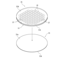
添付図面を参照して、本発明の実施形態について説明する。図1は、本実施形態の研削方法において、被加工物11に支持部材21が固定される様子を示す斜視図である。図1に示すように、本実施形態の被加工物11は、例えば、シリコン等の半導体を用いて円盤状に形成されたウェーハであり、円形状の表面(第1面)11aと、表面11aとは反対側の円形状の裏面(第2面)11bと、を含む。
An embodiment of the present invention will be described with reference to the attached drawings. FIG. 1 is a perspective view showing how a
この被加工物11の表面11aは、その直径の方向において中央側に位置するデバイス領域11cと、デバイス領域11cを囲む環状の外周余剰領域11dと、に分けられる。デバイス領域11cは、互いに交差する複数の分割予定ライン(ストリート)13(図2参照)によって、後に、複数の小領域に区画され、各小領域には、IC(Integrated Circuit)等のデバイス15(図2参照)が形成される。つまり、このデバイス領域11cは、後に複数のデバイス15が形成される予定の領域である。
The
なお、本実施形態では、シリコン等の半導体材料でなる円盤状のウェーハを被加工物11としているが、被加工物11の材質、形状、構造、大きさ等に制限はない。例えば、他の半導体、セラミックス、樹脂、金属等の材料でなる基板を被加工物11として用いることもできる。
In this embodiment, the
本実施形態にかかる研削方法では、まず、上述した被加工物11の裏面11bに、支持部材21を固定する(固定ステップ)。図1に示すように、支持部材21は、例えば、被加工物11と同様に構成された円盤状のウェーハであり、概ね平坦な円形状の表面(第1面)21aと、表面21aとは反対側の円形状の裏面(第2面)21bと、を含む。つまり、支持部材21は、被加工物11のデバイス領域11cよりも大きな表面21a及び裏面21bを有している。
In the grinding method according to this embodiment, first, the
被加工物11に対する支持部材21の固定には、例えば、被加工物11と支持部材21とが接触する領域に熱酸化による酸化膜を形成する酸化膜結合と呼ばれる方法が用いられる。この場合には、被加工物11(裏面11b)と支持部材21(表面11a)とを接触させた状態で、これらを炉に投入し、1000℃以上(例えば、1200℃)で1時間以上(例えば、3時間)の熱処理を行う。これにより、被加工物11と支持部材21との界面に熱酸化による酸化膜を形成し、支持部材21の表面21aを被加工物11の裏面11bに強く固定できる。
To fix the
なお、被加工物11に対する支持部材21の固定には、酸化膜結合以外の方法が用いられても良い。具体的には、例えば、分子間力によって支持部材21(表面21a)を被加工物11(裏面11b)に接合する方法や、樹脂等の接着剤によって支持部材21(表面21a)を被加工物11(裏面11b)に接着する方法等を用いることができる。これらの方法を用いる場合には、酸化膜結合に比べて低い温度で支持部材21を被加工物11に固定できる。
Methods other than oxide film bonding may be used to fix the
支持部材21の表面21aを被加工物11の裏面11bに固定した後には、被加工物11の露出した表面11aにIC等のデバイス15を形成する(デバイス形成ステップ)。例えば、フォトリソグラフィやエッチング等の方法を利用することにより、被加工物11の表面11a側を加工してデバイス15を形成できる。なお、この被加工物11に形成されるデバイス15の種類、数量、形状、構造、大きさ、配置等に制限はない。
After the
被加工物11の表面11aにデバイス15を形成した後には、この被加工物11の表面11aに保護部材を貼付する(貼付ステップ)。図2は、被加工物11に保護部材31が貼付される様子を示す斜視図である。保護部材31は、代表的には、円形状のテープ(フィルム)、樹脂基板、被加工物11と同種又は異種のウェーハ等であり、被加工物11の表面11aと概ね同じ直径を持つ円形状の表面(第1面)31aと、表面31aとは反対側の円形状の裏面(第2面)31bと、を含む。
After forming the
保護部材31の表面31aには、例えば、被加工物11の表面11aに対する接着力を示す接着層が設けられている。そのため、図2に示すように、保護部材31の表面31a側を被加工物11の表面11a側に密着させることで、保護部材31は、被加工物11に貼付される。被加工物11の表面11a側に保護部材31を貼付することで、被加工物11や支持部材21を研削する際に被加工物11の表面11a側に加わる衝撃を緩和して、デバイス15等を保護できる。
For example, an adhesive layer that exhibits adhesive strength to the
被加工物11の表面11aに保護部材31を貼付した後には、この被加工物11の表面11a側をチャックテーブルにより保持する(保持ステップ)。つまり、被加工物11に貼付されている保護部材31をチャックテーブルにより保持する。図3は、被加工物11に貼付されている保護部材31がチャックテーブル4により保持される様子を示す断面図である。なお、以下の各工程では、図3等に示す研削装置2が使用される。
After the
研削装置2は、被加工物11を保持できるように構成されたチャックテーブル4を備えている。チャックテーブル4は、例えば、ステンレス鋼に代表される金属を用いて形成された円盤状の枠体6を含む。枠体6の上面側には、円形状の開口を上端に持つ凹部6aが形成されている。この凹部6aには、セラミックス等を用いて多孔質の円盤状に形成された保持板8が固定されている。
The
保持板8の上面8aは、円錐の側面に相当する形状に構成されており、この上面8aに保護部材31の裏面31bが接触する。保持板8の下面側は、枠体6の内部に設けられた流路6bや、バルブ(不図示)等を介して、エジェクタ等の吸引源(不図示)に接続されている。そのため、保持板8の上面8aに保護部材31の裏面31bを接触させて、バルブを開き、吸引源の負圧を作用させれば、この保護部材31の裏面31bがチャックテーブル4により吸引される。
The
つまり、支持部材21が固定された状態の被加工物11に貼付されている保護部材31を、チャックテーブル4により保持できる。これにより、図3に示すように、支持部材21の裏面21bが上方に露出した状態になる。なお、図3等では、保持板8の上面8aを構成する円錐の側面の形状が誇張されているが、実際には、上面8aの最も高い点と最も低い点との高さの差(高低差)が10μm~30μm程度である。
In other words, the
枠体6の下部には、モーター等の回転駆動源(不図示)が連結されている。チャックテーブル4は、この回転駆動源が生じる力によって、円錐の頂点に相当する上面8aの頂点8bが回転の中心となるように、鉛直方向に沿う軸、又は鉛直方向に対して僅かに傾いた軸の周りに回転する。また、枠体6は、移動機構(不図示)によって支持されており、チャックテーブル4は、この移動機構が生じる力によって、水平方向に移動する。
A rotary drive source (not shown) such as a motor is connected to the bottom of the
被加工物11に貼付されている保護部材31をチャックテーブル4で保持した後には、例えば、鉛直方向から見て被加工物11のデバイス領域11cに重なる支持部材21の領域を研削し、被加工物11に固定された状態の環状の補強部材を形成する(支持部材研削ステップ)。図4は、支持部材21が研削される様子を示す断面図である。なお、図4では、説明の便宜上、一部の要素が側面により示されている。
After the
図4等に示すように、研削装置2のチャックテーブル4の上方には、研削ユニット(第1研削ユニット)10が配置されている。研削ユニット10は、例えば、筒状のスピンドルハウジング(不図示)を含む。スピンドルハウジングの内側の空間には、柱状のスピンドル12が収容されている。
As shown in FIG. 4 etc., a grinding unit (first grinding unit) 10 is disposed above the chuck table 4 of the grinding
スピンドル12の下端部には、例えば、被加工物11や支持部材21よりも直径の小さな円盤状のマウント14が設けられている。マウント14の外周部には、このマウント14を厚さの方向に貫通する複数の穴(不図示)が形成されており、各穴には、ボルト16等が挿入される。マウント14の下面には、このマウント14と概ね直径が等しい円盤状の研削ホイール18が、ボルト16等によって固定されている。
At the lower end of the
研削ホイール18は、ステンレス鋼やアルミニウム等の金属を用いて形成された円盤状のホイール基台20を含む。ホイール基台20の下面には、このホイール基台20の周方向に沿って複数の研削砥石22が固定されている。スピンドル12の上端側には、モーター等の回転駆動源(不図示)が連結されている。研削ホイール18は、この回転駆動源が生じる力によって、鉛直方向に沿う軸、又は鉛直方向に対して僅かに傾いた軸の周りに回転する。
The grinding
研削ホイール18の傍、又は研削ホイール18の内部には、研削砥石22等に対して研削用の液体(代表的には、水)を供給できるように構成されたノズル(不図示)が設けられている。スピンドルハウジングは、例えば、移動機構(不図示)によって支持されており、研削ユニット10は、この移動機構が生じる力によって、鉛直方向に移動する。
A nozzle (not shown) configured to supply a grinding liquid (typically water) to the grinding
支持部材21を研削する際には、まず、チャックテーブル4を研削ユニット10の直下に移動させる。具体的には、複数の研削砥石22の全てがデバイス領域11cの直上に配置されるように、チャックテーブル4を移動させる。また、研削ホイール18の直径の方向において最も外側に位置する研削砥石22の端部のいずれかが、デバイス領域11cと外周余剰領域11dとの境界より僅かに内側の位置の直上に配置されるように、チャックテーブル4を移動させる。
When grinding the
そして、図4に示すように、チャックテーブル4と研削ホイール18とをそれぞれ回転させて、ノズルから液体を供給しながら研削ユニット10(スピンドル12、研削ホイール18)を下降させる。研削ユニット10の下降の速度は、支持部材21に対して研削砥石22が適切な圧力で押し当てられる範囲に調整される。これにより、支持部材21のデバイス領域11cに対応する領域を裏面21bから研削できる。
Then, as shown in FIG. 4, the chuck table 4 and the
より具体的には、チャックテーブル4の回転数を、100rpm~600rpm、代表的には、300rpmに設定し、研削ホイール18の回転数を、1000rpm~7000rpm、代表的には、4000rpmに設定し、研削ユニット10の下降の速度を、0.2μm/s~10μm/s、代表的には、0.6μm/sに設定すると良い。これにより、支持部材21を適切に研削できる。
More specifically, the rotation speed of the chuck table 4 is set to 100 rpm to 600 rpm, typically 300 rpm, the rotation speed of the
支持部材21の研削は、この支持部材21が裏面21bから表面21aまで貫通されて環状の補強部材が完成するまで続けられる。図5は、環状の補強部材23が形成される様子を示す断面図である。なお、図5では、説明の便宜上、一部の要素が側面により示されている。
Grinding of the
図5に示すように、環状の補強部材23は、支持部材21のデバイス領域11cに対応する領域が除去されてなる貫通穴23aを有している。つまり、貫通穴23aは、支持部材21のデバイス領域11cに対応する位置に形成される。よって、この支持部材21の研削によって、被加工物11の外周余剰領域11dの裏面11b側に固定された状態の環状の補強部材23が形成される。
As shown in FIG. 5, the annular reinforcing
支持部材21の研削が終了した後には、引き続いて、被加工物11のデバイス領域11cに対応する領域を裏面11bから研削して仕上げ厚さまで薄くする(被加工物研削ステップ)。図6は、被加工物11が研削される様子を示す断面図である。なお、図6では、説明の便宜上、一部の要素が側面により示されている。
After grinding of the
被加工物11を研削する際には、支持部材21を研削する場合と同様に、チャックテーブル4と研削ホイール18とをそれぞれ回転させた状態で、ノズルから液体を供給しながら研削ユニット10(スピンドル12、研削ホイール18)を下降させる。研削ユニット10の下降の速度は、被加工物11に対して研削砥石22が適切な圧力で押し当てられる範囲に調整される。これにより、被加工物11のデバイス領域11cに対応する領域を裏面11bから研削できる。
When grinding the
なお、本実施形態では、この被加工物11の研削と、上述した支持部材21の研削と、が同等の条件で連続的に行われる。つまり、被加工物11を研削する際にも、チャックテーブル4の回転数を、100rpm~600rpm、代表的には、300rpmに設定し、研削ホイール18の回転数を、1000rpm~7000rpm、代表的には、4000rpmに設定し、研削ユニット10の下降の速度を、0.2μm/s~10μm/s、代表的には、0.6μm/sに設定すると良い。
In this embodiment, the grinding of the
なお、上述した研削の条件を途中で変更することもできる。例えば、被加工物11のデバイス領域11cに対応する領域がある程度に薄くなった段階で、研削ユニット10の下降の速度を下げることにより、研削による被加工物11へのダメージを軽減できる。この場合には、研削ユニット10の下降の速度を、0.1μm/s~0.5μm/s、代表的には、0.3μm/sに設定すると良い。
The above-mentioned grinding conditions can also be changed midway through the process. For example, when the area of the
被加工物11の研削は、この被加工物11のデバイス領域11cに対応する領域が仕上げ厚さまで薄くなり、デバイス領域11cに対応する薄板部11eと、薄板部11eを囲み環状の補強部材23が固定された厚板部11fと、が完成するまで続けられる。被加工物11の研削が終了すると、本実施形態の研削方法も終了する。
Grinding of the
以上のように、本実施形態の研削方法では、支持部材21の表面21aを被加工物11の裏面11bに固定した上で、支持部材21のデバイス領域11cに対応する領域を支持部材21の裏面21bから研削して環状の補強部材23を形成するとともに、被加工物11のデバイス領域11cに対応する領域を被加工物11の裏面11bから研削して、デバイス領域11cに対応する薄板部11eと、薄板部11eを囲み補強部材23が固定された厚板部11fと、を形成するので、研削後の被加工物11は、環状の補強部材23により補強された状態となる。よって、研削後の被加工物11に高い剛性を付与できる。
As described above, in the grinding method of this embodiment, the
なお、本発明は、上述した実施形態の記載に制限されず種々変更して実施可能である。例えば、上述した実施形態では、支持部材21の研削(支持部材研削ステップ)と、被加工物11の研削(被加工物研削ステップ)と、を同等の条件で連続的に行っているが、支持部材21の研削(支持部材研削ステップ)と、被加工物11の研削(被加工物研削ステップ)と、を異なる条件で断続的に行っても良い。 The present invention is not limited to the above-described embodiment, and can be modified in various ways. For example, in the above-described embodiment, grinding of the support member 21 (support member grinding step) and grinding of the workpiece 11 (workpiece grinding step) are performed continuously under the same conditions, but grinding of the support member 21 (support member grinding step) and grinding of the workpiece 11 (workpiece grinding step) may be performed intermittently under different conditions.
また、支持部材21や被加工物11のデバイス領域11cに対応する領域を研削する前に、支持部材21の裏面21bの全体を研削して支持部材21を全体的に薄くしても良い(支持部材全体研削ステップ)。図7は、変形例にかかる研削方法において、支持部材21の裏面21bの全体が研削される様子を示す断面図である。なお、図7では、説明の便宜上、一部の要素が側面により示されている。
Also, before grinding the
変形例にかかる研削方法では、被加工物11の表面11a側をチャックテーブル4により保持した後、支持部材21のデバイス領域11cに対応する領域を研削する前に、支持部材21の裏面21bの全体を研削する。この変形例にかかる研削方法で使用される研削装置2は、図7に示すように、研削ユニット(第1研削ユニット)10とは別の研削ユニット(第2研削ユニット)24をチャックテーブル4の上方に備えている。
In the grinding method according to the modified example, the
研削ユニット24の基本的な構造は、研削ユニット10と同じである。すなわち、研削ユニット24は、例えば、筒状のスピンドルハウジング(不図示)を含む。スピンドルハウジングの内側の空間には、柱状のスピンドル26が収容されている。スピンドル26の下端部には、例えば、被加工物11や支持部材21よりも直径の大きな円盤状のマウント28が設けられている。
The basic structure of the grinding
マウント28の外周部には、このマウント28を貫通する複数の穴(不図示)が形成されており、各穴には、ボルト30等が挿入される。マウント28の下面には、このマウント28と概ね直径が等しい円盤状の研削ホイール32が、マウント28の穴に挿入されたボルト30等によって固定されている。
A number of holes (not shown) are formed on the outer periphery of the
研削ホイール32は、ステンレス鋼やアルミニウム等の金属を用いて形成されたホイール基台34を含む。ホイール基台34の下面には、このホイール基台34の周方向に沿って複数の研削砥石36が固定されている。スピンドル26の上端側には、モーター等の回転駆動源(不図示)が連結されている。研削ホイール32は、この回転駆動源が生じる力によって、鉛直方向に沿う軸、又は鉛直方向に対して僅かに傾いた軸の周りに回転する。
The grinding
研削ホイール32の傍、又は研削ホイール32の内部には、研削砥石36等に対して研削用の液体(代表的には、水)を供給できるように構成されたノズル(不図示)が設けられている。スピンドルハウジングは、例えば、移動機構(不図示)によって支持されており、研削ユニット24は、この移動機構が生じる力によって、鉛直方向に移動する。
A nozzle (not shown) configured to supply a grinding liquid (typically water) to the grinding
支持部材21の裏面21bの全体を研削する際には、まず、チャックテーブル4を研削ユニット24の直下に移動させる。そして、図7に示すように、チャックテーブル4と研削ホイール32とをそれぞれ回転させて、ノズルから液体を供給しながら研削ユニット24(スピンドル26、研削ホイール32)を下降させる。研削ユニット24の下降の速度は、支持部材21に対して研削砥石36が適切な圧力で押し当てられる範囲に調整される。これにより、支持部材21の裏面21bの全体を研削できる。
When grinding the
より具体的には、チャックテーブル4の回転数を100rpm~600rpm、代表的には、300rpmに設定し、研削ホイール32の回転数を1000rpm~7000rpm、代表的には、4000rpmに設定し、研削ユニット24の下降の速度を0.2μm/s~10μm/s、代表的には、0.4μm/sに設定すると良い。
More specifically, the rotation speed of the chuck table 4 is set to 100 rpm to 600 rpm, typically 300 rpm, the rotation speed of the
これにより、支持部材21の全体を適切に研削できる。なお、研削ユニット24による支持部材21の研削は、支持部材21が適切な厚さに薄くなるまで続けられる。支持部材21の全体を研削した後には、支持部材21や被加工物11のデバイス領域11cに対応する領域を上述した研削ユニット10で研削すれば良い。
This allows the
また、被加工物11に支持部材21を固定する前に、複数のデバイス15をデバイス領域11cに形成することもできる。この場合には、複数のデバイス15が形成された状態の被加工物11が支持部材21に固定されることになる。図8は、第2変形例にかかる研削方法において、被加工物11に支持部材21が固定される様子を示す斜視図である。
Also,
第2変形例にかかる研削方法では、被加工物11にデバイス15を形成してから支持部材21を固定する。よって、高温での熱処理が必要な酸化膜結合等の方法を用いると、デバイス15が破損する可能性も高くなる。したがって、この第2変形例にかかる研削方法では、分子間力によって支持部材21(表面21a)を被加工物11(裏面11b)に接合する方法や、樹脂等の接着剤によって支持部材21(表面21a)を被加工物11(裏面11b)に接着する方法等を用いることが望ましい。
In the grinding method according to the second modified example, the
なお、被加工物11に支持部材21を固定した後には、上述した実施形態や第1変形例と同様の手順で被加工物11を研削すれば良い。
After the
その他、上述した実施形態及び各変形例にかかる構造、方法等は、本発明の目的の範囲を逸脱しない限りにおいて適宜変更して実施できる。 In addition, the structures, methods, etc. of the above-described embodiments and each modified example can be modified as appropriate without departing from the scope of the purpose of the present invention.
11 :被加工物
11a :表面(第1面)
11b :裏面(第2面)
11c :デバイス領域
11d :外周余剰領域
11e :薄板部
11f :厚板部
13 :分割予定ライン(ストリート)
15 :デバイス
21 :支持部材
21a :表面(第1面)
21b :裏面(第2面)
23 :補強部材
23a :貫通穴
31 :保護部材
31a :表面(第1面)
31b :裏面(第2面)
2 :研削装置
4 :チャックテーブル
6 :枠体
6a :凹部
6b :流路
8 :保持板
8a :上面
8b :頂点
10 :研削ユニット(第1研削ユニット)
12 :スピンドル
14 :マウント
16 :ボルト
18 :研削ホイール
20 :ホイール基台
22 :研削砥石
24 :研削ユニット(第2研削ユニット)
26 :スピンドル
28 :マウント
30 :ボルト
32 :研削ホイール
34 :ホイール基台
36 :研削砥石
11:
11b: Back side (second side)
11c:
15: Device 21:
21b: Back side (second side)
23: Reinforcing
31b: Back side (second side)
2: Grinding device 4: Chuck table 6:
12: Spindle 14: Mount 16: Bolt 18: Grinding wheel 20: Wheel base 22: Grinding stone 24: Grinding unit (second grinding unit)
26: Spindle 28: Mount 30: Bolt 32: Grinding wheel 34: Wheel base 36: Grinding stone
Claims (2)
該デバイス領域よりも大きな表面を有する支持部材の該表面を該被加工物の該裏面に固定する固定ステップと、
該被加工物の該表面に保護部材を貼付する貼付ステップと、
該支持部材が固定された該被加工物に貼付されている該保護部材をチャックテーブルで保持する保持ステップと、
該保護部材を介して該被加工物及び該支持部材が該チャックテーブルに保持された状態で、該支持部材の該デバイス領域に対応する領域を該支持部材の該表面とは反対側の裏面から研削して該支持部材を該裏面から該表面まで貫通させることにより、環状の補強部材を形成し、更に、該被加工物の該デバイス領域に対応する領域を該被加工物の該裏面から研削して該デバイス領域に対応する領域を仕上げ厚さまで薄くすることにより、該デバイス領域に対応する薄板部と、該薄板部を囲み該補強部材が固定された厚板部と、を形成する研削ステップと、を含み、
該固定ステップの前に、複数の該デバイスを該デバイス領域に形成するデバイス形成ステップを更に含むことを特徴とする研削方法。 A grinding method for grinding a back surface of a plate-shaped workpiece having a device region on a surface on which a plurality of devices are formed or to be formed, and a peripheral excess region surrounding the device region, the back surface being opposite to the front surface, with a grinding wheel attached to a spindle, the method comprising:
a fixing step of fixing a surface of a support member having a surface larger than the device area to the back surface of the workpiece;
a step of attaching a protective member to the surface of the workpiece;
a holding step of holding, by a chuck table, the protective member attached to the workpiece to which the support member is fixed;
a grinding step of grinding a region of the support member corresponding to the device region from a back surface opposite to the front surface of the support member while the workpiece and the support member are held on the chuck table via the protective member, thereby penetrating the support member from the back surface to the front surface, thereby forming an annular reinforcing member, and further grinding the region of the workpiece corresponding to the device region from the back surface of the workpiece to thin the region corresponding to the device region to a finishing thickness, thereby forming a thin plate portion corresponding to the device region and a thick plate portion surrounding the thin plate portion and to which the reinforcing member is fixed ,
The grinding method further comprises, before the fixing step, a device forming step of forming a plurality of the devices in the device region .
Priority Applications (4)
| Application Number | Priority Date | Filing Date | Title |
|---|---|---|---|
| JP2020149877A JP7588931B2 (en) | 2020-09-07 | 2020-09-07 | Grinding Method |
| KR1020210108408A KR102912760B1 (en) | 2020-09-07 | 2021-08-18 | Grinding method |
| CN202111025660.1A CN114147545A (en) | 2020-09-07 | 2021-09-02 | Grinding method |
| TW110132863A TWI896752B (en) | 2020-09-07 | 2021-09-03 | Grinding method |
Applications Claiming Priority (1)
| Application Number | Priority Date | Filing Date | Title |
|---|---|---|---|
| JP2020149877A JP7588931B2 (en) | 2020-09-07 | 2020-09-07 | Grinding Method |
Publications (2)
| Publication Number | Publication Date |
|---|---|
| JP2022044315A JP2022044315A (en) | 2022-03-17 |
| JP7588931B2 true JP7588931B2 (en) | 2024-11-25 |
Family
ID=80462460
Family Applications (1)
| Application Number | Title | Priority Date | Filing Date |
|---|---|---|---|
| JP2020149877A Active JP7588931B2 (en) | 2020-09-07 | 2020-09-07 | Grinding Method |
Country Status (4)
| Country | Link |
|---|---|
| JP (1) | JP7588931B2 (en) |
| KR (1) | KR102912760B1 (en) |
| CN (1) | CN114147545A (en) |
| TW (1) | TWI896752B (en) |
Families Citing this family (1)
| Publication number | Priority date | Publication date | Assignee | Title |
|---|---|---|---|---|
| JP2024167623A (en) | 2023-05-22 | 2024-12-04 | 株式会社ディスコ | WAFER PROCESSING APPARATUS AND WAFER PROCESSING METHOD |
Citations (3)
| Publication number | Priority date | Publication date | Assignee | Title |
|---|---|---|---|---|
| JP2005294623A (en) | 2004-04-01 | 2005-10-20 | Disco Abrasive Syst Ltd | Wafer processing method |
| JP2011165771A (en) | 2010-02-05 | 2011-08-25 | Fuji Electric Co Ltd | Method of manufacturing semiconductor device |
| JP2020009955A (en) | 2018-07-10 | 2020-01-16 | 株式会社ディスコ | Processing method of wafer |
Family Cites Families (6)
| Publication number | Priority date | Publication date | Assignee | Title |
|---|---|---|---|---|
| WO2006090650A1 (en) * | 2005-02-23 | 2006-08-31 | Jsr Corporation | Method for processing wafer |
| JP5390740B2 (en) | 2005-04-27 | 2014-01-15 | 株式会社ディスコ | Wafer processing method |
| JP4986568B2 (en) * | 2006-10-11 | 2012-07-25 | 株式会社ディスコ | Wafer grinding method |
| JP6096085B2 (en) * | 2013-08-30 | 2017-03-15 | 富士フイルム株式会社 | Laminate and its application |
| JP6791579B2 (en) * | 2016-09-09 | 2020-11-25 | 株式会社ディスコ | Wafers and wafer processing methods |
| JP7049801B2 (en) * | 2017-10-12 | 2022-04-07 | 株式会社ディスコ | Grinding method for workpieces |
-
2020
- 2020-09-07 JP JP2020149877A patent/JP7588931B2/en active Active
-
2021
- 2021-08-18 KR KR1020210108408A patent/KR102912760B1/en active Active
- 2021-09-02 CN CN202111025660.1A patent/CN114147545A/en active Pending
- 2021-09-03 TW TW110132863A patent/TWI896752B/en active
Patent Citations (3)
| Publication number | Priority date | Publication date | Assignee | Title |
|---|---|---|---|---|
| JP2005294623A (en) | 2004-04-01 | 2005-10-20 | Disco Abrasive Syst Ltd | Wafer processing method |
| JP2011165771A (en) | 2010-02-05 | 2011-08-25 | Fuji Electric Co Ltd | Method of manufacturing semiconductor device |
| JP2020009955A (en) | 2018-07-10 | 2020-01-16 | 株式会社ディスコ | Processing method of wafer |
Also Published As
| Publication number | Publication date |
|---|---|
| KR102912760B1 (en) | 2026-01-14 |
| TWI896752B (en) | 2025-09-11 |
| TW202210226A (en) | 2022-03-16 |
| JP2022044315A (en) | 2022-03-17 |
| CN114147545A (en) | 2022-03-08 |
| KR20220032479A (en) | 2022-03-15 |
Similar Documents
| Publication | Publication Date | Title |
|---|---|---|
| JP7701191B2 (en) | Wafer Processing Method | |
| CN107808898B (en) | Wafer and wafer processing method | |
| JP2009021462A (en) | Wafer processing method | |
| TWI805872B (en) | Wafer processing method | |
| JP5068705B2 (en) | Chuck table of processing equipment | |
| CN102848305B (en) | The method for grinding of machined object | |
| CN113400101A (en) | Grinding method | |
| US20190111537A1 (en) | Workpiece grinding method | |
| KR102912760B1 (en) | Grinding method | |
| JP2011071287A (en) | Method of processing wafer | |
| US20230398654A1 (en) | Workpiece grinding method | |
| JP7718825B2 (en) | Grinding method for workpiece | |
| JP7704634B2 (en) | Method for grinding a workpiece | |
| JP7828185B2 (en) | Grinding Method | |
| JP7828169B2 (en) | Wafer processing method and chip manufacturing method | |
| JP7614711B2 (en) | Method for processing workpiece | |
| JP7845949B2 (en) | Grinding method for workpieces | |
| JP5000915B2 (en) | Resin coating method and coating apparatus | |
| JP2025014364A (en) | Wafer grinding method | |
| JP2024059330A (en) | Grinding wheel and work-piece grinding method | |
| TW202331831A (en) | The processing method of the processed object | |
| CN116487243A (en) | Processing method of bonded wafer | |
| JP2022104194A (en) | Holding jig and grinding method of workpiece |
Legal Events
| Date | Code | Title | Description |
|---|---|---|---|
| A621 | Written request for application examination |
Free format text: JAPANESE INTERMEDIATE CODE: A621 Effective date: 20230725 |
|
| A977 | Report on retrieval |
Free format text: JAPANESE INTERMEDIATE CODE: A971007 Effective date: 20240531 |
|
| A131 | Notification of reasons for refusal |
Free format text: JAPANESE INTERMEDIATE CODE: A131 Effective date: 20240618 |
|
| A521 | Request for written amendment filed |
Free format text: JAPANESE INTERMEDIATE CODE: A523 Effective date: 20240815 |
|
| TRDD | Decision of grant or rejection written | ||
| A01 | Written decision to grant a patent or to grant a registration (utility model) |
Free format text: JAPANESE INTERMEDIATE CODE: A01 Effective date: 20241112 |
|
| A61 | First payment of annual fees (during grant procedure) |
Free format text: JAPANESE INTERMEDIATE CODE: A61 Effective date: 20241112 |
|
| R150 | Certificate of patent or registration of utility model |
Ref document number: 7588931 Country of ref document: JP Free format text: JAPANESE INTERMEDIATE CODE: R150 |