JP7597823B2 - Apparatus and method for joining multi-part tampon applicators - Patents.com - Google Patents
Apparatus and method for joining multi-part tampon applicators - Patents.com Download PDFInfo
- Publication number
- JP7597823B2 JP7597823B2 JP2022551655A JP2022551655A JP7597823B2 JP 7597823 B2 JP7597823 B2 JP 7597823B2 JP 2022551655 A JP2022551655 A JP 2022551655A JP 2022551655 A JP2022551655 A JP 2022551655A JP 7597823 B2 JP7597823 B2 JP 7597823B2
- Authority
- JP
- Japan
- Prior art keywords
- receiving
- station
- joining
- inner cylinder
- barrel
- Prior art date
- Legal status (The legal status is an assumption and is not a legal conclusion. Google has not performed a legal analysis and makes no representation as to the accuracy of the status listed.)
- Active
Links
Images




Classifications
-
- A—HUMAN NECESSITIES
- A61—MEDICAL OR VETERINARY SCIENCE; HYGIENE
- A61F—FILTERS IMPLANTABLE INTO BLOOD VESSELS; PROSTHESES; DEVICES PROVIDING PATENCY TO, OR PREVENTING COLLAPSING OF, TUBULAR STRUCTURES OF THE BODY, e.g. STENTS; ORTHOPAEDIC, NURSING OR CONTRACEPTIVE DEVICES; FOMENTATION; TREATMENT OR PROTECTION OF EYES OR EARS; BANDAGES, DRESSINGS OR ABSORBENT PADS; FIRST-AID KITS
- A61F13/00—Bandages or dressings; Absorbent pads
- A61F13/15—Absorbent pads, e.g. sanitary towels, swabs or tampons for external or internal application to the body; Supporting or fastening means therefor; Tampon applicators
- A61F13/20—Tampons, e.g. catamenial tampons; Accessories therefor
- A61F13/2082—Apparatus or processes of manufacturing
- A61F13/2085—Catamenial tampons
- A61F13/2097—Catamenial tampons method of manufacturing tampon applicators
-
- A—HUMAN NECESSITIES
- A61—MEDICAL OR VETERINARY SCIENCE; HYGIENE
- A61F—FILTERS IMPLANTABLE INTO BLOOD VESSELS; PROSTHESES; DEVICES PROVIDING PATENCY TO, OR PREVENTING COLLAPSING OF, TUBULAR STRUCTURES OF THE BODY, e.g. STENTS; ORTHOPAEDIC, NURSING OR CONTRACEPTIVE DEVICES; FOMENTATION; TREATMENT OR PROTECTION OF EYES OR EARS; BANDAGES, DRESSINGS OR ABSORBENT PADS; FIRST-AID KITS
- A61F13/00—Bandages or dressings; Absorbent pads
- A61F13/15—Absorbent pads, e.g. sanitary towels, swabs or tampons for external or internal application to the body; Supporting or fastening means therefor; Tampon applicators
- A61F13/20—Tampons, e.g. catamenial tampons; Accessories therefor
- A61F13/2082—Apparatus or processes of manufacturing
-
- A—HUMAN NECESSITIES
- A61—MEDICAL OR VETERINARY SCIENCE; HYGIENE
- A61F—FILTERS IMPLANTABLE INTO BLOOD VESSELS; PROSTHESES; DEVICES PROVIDING PATENCY TO, OR PREVENTING COLLAPSING OF, TUBULAR STRUCTURES OF THE BODY, e.g. STENTS; ORTHOPAEDIC, NURSING OR CONTRACEPTIVE DEVICES; FOMENTATION; TREATMENT OR PROTECTION OF EYES OR EARS; BANDAGES, DRESSINGS OR ABSORBENT PADS; FIRST-AID KITS
- A61F13/00—Bandages or dressings; Absorbent pads
- A61F13/15—Absorbent pads, e.g. sanitary towels, swabs or tampons for external or internal application to the body; Supporting or fastening means therefor; Tampon applicators
- A61F13/20—Tampons, e.g. catamenial tampons; Accessories therefor
- A61F13/26—Means for inserting tampons, i.e. applicators
-
- A—HUMAN NECESSITIES
- A61—MEDICAL OR VETERINARY SCIENCE; HYGIENE
- A61F—FILTERS IMPLANTABLE INTO BLOOD VESSELS; PROSTHESES; DEVICES PROVIDING PATENCY TO, OR PREVENTING COLLAPSING OF, TUBULAR STRUCTURES OF THE BODY, e.g. STENTS; ORTHOPAEDIC, NURSING OR CONTRACEPTIVE DEVICES; FOMENTATION; TREATMENT OR PROTECTION OF EYES OR EARS; BANDAGES, DRESSINGS OR ABSORBENT PADS; FIRST-AID KITS
- A61F13/00—Bandages or dressings; Absorbent pads
- A61F13/15—Absorbent pads, e.g. sanitary towels, swabs or tampons for external or internal application to the body; Supporting or fastening means therefor; Tampon applicators
- A61F13/20—Tampons, e.g. catamenial tampons; Accessories therefor
- A61F13/26—Means for inserting tampons, i.e. applicators
- A61F13/263—Means for inserting tampons, i.e. applicators with reduced length before use, e.g. with folding rod
-
- A—HUMAN NECESSITIES
- A61—MEDICAL OR VETERINARY SCIENCE; HYGIENE
- A61F—FILTERS IMPLANTABLE INTO BLOOD VESSELS; PROSTHESES; DEVICES PROVIDING PATENCY TO, OR PREVENTING COLLAPSING OF, TUBULAR STRUCTURES OF THE BODY, e.g. STENTS; ORTHOPAEDIC, NURSING OR CONTRACEPTIVE DEVICES; FOMENTATION; TREATMENT OR PROTECTION OF EYES OR EARS; BANDAGES, DRESSINGS OR ABSORBENT PADS; FIRST-AID KITS
- A61F13/00—Bandages or dressings; Absorbent pads
- A61F13/15—Absorbent pads, e.g. sanitary towels, swabs or tampons for external or internal application to the body; Supporting or fastening means therefor; Tampon applicators
- A61F13/20—Tampons, e.g. catamenial tampons; Accessories therefor
- A61F13/26—Means for inserting tampons, i.e. applicators
- A61F13/266—Insertion devices, e.g. rods or plungers, separate from the tampon
-
- B—PERFORMING OPERATIONS; TRANSPORTING
- B29—WORKING OF PLASTICS; WORKING OF SUBSTANCES IN A PLASTIC STATE IN GENERAL
- B29C—SHAPING OR JOINING OF PLASTICS; SHAPING OF MATERIAL IN A PLASTIC STATE, NOT OTHERWISE PROVIDED FOR; AFTER-TREATMENT OF THE SHAPED PRODUCTS, e.g. REPAIRING
- B29C49/00—Blow-moulding, i.e. blowing a preform or parison to a desired shape within a mould; Apparatus therefor
- B29C49/42—Component parts, details or accessories; Auxiliary operations
- B29C49/4205—Handling means, e.g. transfer, loading or discharging means
- B29C49/42093—Transporting apparatus, e.g. slides, wheels or conveyors
- B29C49/42095—Rotating wheels or stars
-
- B—PERFORMING OPERATIONS; TRANSPORTING
- B65—CONVEYING; PACKING; STORING; HANDLING THIN OR FILAMENTARY MATERIAL
- B65G—TRANSPORT OR STORAGE DEVICES, e.g. CONVEYORS FOR LOADING OR TIPPING, SHOP CONVEYOR SYSTEMS OR PNEUMATIC TUBE CONVEYORS
- B65G47/00—Article or material-handling devices associated with conveyors; Methods employing such devices
- B65G47/74—Feeding, transfer, or discharging devices of particular kinds or types
- B65G47/90—Devices for picking-up and depositing articles or materials
- B65G47/904—Devices for picking-up and depositing articles or materials provided with rotary movements only
-
- B—PERFORMING OPERATIONS; TRANSPORTING
- B65—CONVEYING; PACKING; STORING; HANDLING THIN OR FILAMENTARY MATERIAL
- B65G—TRANSPORT OR STORAGE DEVICES, e.g. CONVEYORS FOR LOADING OR TIPPING, SHOP CONVEYOR SYSTEMS OR PNEUMATIC TUBE CONVEYORS
- B65G47/00—Article or material-handling devices associated with conveyors; Methods employing such devices
- B65G47/74—Feeding, transfer, or discharging devices of particular kinds or types
- B65G47/90—Devices for picking-up and depositing articles or materials
- B65G47/907—Devices for picking-up and depositing articles or materials with at least two picking-up heads
-
- B—PERFORMING OPERATIONS; TRANSPORTING
- B65—CONVEYING; PACKING; STORING; HANDLING THIN OR FILAMENTARY MATERIAL
- B65G—TRANSPORT OR STORAGE DEVICES, e.g. CONVEYORS FOR LOADING OR TIPPING, SHOP CONVEYOR SYSTEMS OR PNEUMATIC TUBE CONVEYORS
- B65G49/00—Conveying systems characterised by their application for specified purposes not otherwise provided for
-
- B—PERFORMING OPERATIONS; TRANSPORTING
- B32—LAYERED PRODUCTS
- B32B—LAYERED PRODUCTS, i.e. PRODUCTS BUILT-UP OF STRATA OF FLAT OR NON-FLAT, e.g. CELLULAR OR HONEYCOMB, FORM
- B32B1/00—Layered products having a non-planar shape
- B32B1/08—Tubular products
-
- B—PERFORMING OPERATIONS; TRANSPORTING
- B65—CONVEYING; PACKING; STORING; HANDLING THIN OR FILAMENTARY MATERIAL
- B65G—TRANSPORT OR STORAGE DEVICES, e.g. CONVEYORS FOR LOADING OR TIPPING, SHOP CONVEYOR SYSTEMS OR PNEUMATIC TUBE CONVEYORS
- B65G2201/00—Indexing codes relating to handling devices, e.g. conveyors, characterised by the type of product or load being conveyed or handled
- B65G2201/02—Articles
- B65G2201/0214—Articles of special size, shape or weigh
-
- B—PERFORMING OPERATIONS; TRANSPORTING
- B65—CONVEYING; PACKING; STORING; HANDLING THIN OR FILAMENTARY MATERIAL
- B65G—TRANSPORT OR STORAGE DEVICES, e.g. CONVEYORS FOR LOADING OR TIPPING, SHOP CONVEYOR SYSTEMS OR PNEUMATIC TUBE CONVEYORS
- B65G29/00—Rotary conveyors, e.g. rotating discs, arms, star-wheels or cones
Landscapes
- Health & Medical Sciences (AREA)
- Engineering & Computer Science (AREA)
- Vascular Medicine (AREA)
- Epidemiology (AREA)
- Biomedical Technology (AREA)
- Heart & Thoracic Surgery (AREA)
- Life Sciences & Earth Sciences (AREA)
- Animal Behavior & Ethology (AREA)
- General Health & Medical Sciences (AREA)
- Public Health (AREA)
- Veterinary Medicine (AREA)
- Manufacturing & Machinery (AREA)
- Mechanical Engineering (AREA)
- Absorbent Articles And Supports Therefor (AREA)
- Lining Or Joining Of Plastics Or The Like (AREA)
Description
本発明は、マルチパートタンポンアプリケータを接合するための装置、並びにマルチパートタンポンアプリケータ、詳細には両方とも3パートタンポンアプリケータを接合するための方法に関する。 The present invention relates to an apparatus for joining multi-part tampon applicators, as well as a method for joining multi-part tampon applicators, particularly both three-part tampon applicators.
タンポンアプリケータは、タンポンの挿入補助具である。それらの最も単純な実施形態では、タンポンアプリケータは、タンポンが配置される円筒管である。タンポンアプリケータは、タンポンが身体孔内に配置された後にタンポンが排出される遠位口開口を有する。タンポンアプリケータは、この目的のために対応するプランジャを備えることが多い。最も単純な実施形態では、このプランジャは、管状筒、この場合は内筒としても設計され得る。 Tampon applicators are insertion aids for tampons. In their simplest embodiment, tampon applicators are cylindrical tubes into which the tampon is placed. They have a distal mouth opening through which the tampon is expelled after it has been placed in the body orifice. Tampon applicators are often equipped with a corresponding plunger for this purpose. In the simplest embodiment, this plunger may also be designed as a tubular barrel, in this case an inner barrel.
そのような2パートタンポンアプリケータは、引出し機構をさらに備えることができる。このような、通常は2パートの実施形態では、内筒は、最初は実質的に外筒内に配置され、場合によっては、最初はタンポンを収容することができる。動作中、内筒は、予め張力がかけられた機械的把持装置がタンポンと係合するまで、外筒の近位開口部を通してまず引っ張られる。通常、内筒をあまり遠くに引き抜くことができないように外筒の近位端に停止部が設けられている。この係合が内筒とタンポンとの間の把持接続を作る場合、内筒を外筒内に再び押し込むことにより、タンポンを外筒から変位させ、タンポンを口開口を通して身体孔内に放出することができる。 Such two-part tampon applicators may further include a withdrawal mechanism. In such typically two-part embodiments, the inner barrel is initially disposed substantially within the outer barrel and may, in some cases, initially contain a tampon. In operation, the inner barrel is first pulled through a proximal opening of the outer barrel until a pre-tensioned mechanical gripping device engages the tampon. Typically, a stop is provided at the proximal end of the outer barrel so that the inner barrel cannot be withdrawn too far. When this engagement creates a gripping connection between the inner barrel and the tampon, pushing the inner barrel back into the outer barrel displaces the tampon from the outer barrel and allows the tampon to be expelled through the oral opening and into the body orifice.
ほとんどの場合、タンポンアプリケータは、プラスチック材料で作られ、例えば外筒の近位領域内の適切な位置に把持領域を有する。材料の粗面化、ゴム引き、特別な構造化又は凹状グリップによって、把持特性の改善を確実にすることができる。 In most cases, tampon applicators are made of plastic material and have a gripping area at a suitable location, for example in the proximal region of the barrel. Improved gripping properties can be ensured by roughening the material, rubberizing, special structuring or concave grips.
2パート、3パート、又はさらにマルチパート設計タンポンアプリケータに加えて、例えば、最初にベアリング上で互いに対して変位することができ、相互係合後に剛性プランジャになる複数の内筒を設けることによって、プランジャを少なくとも部分的に伸縮自在に構築することができる。 In addition to two-part, three-part, or even multi-part design tampon applicators, the plunger can be constructed to be at least partially telescopic, for example, by providing multiple inner barrels that can initially be displaced relative to one another on bearings and become rigid plungers after interengagement.
タンポンアプリケータのこれらすべての伸縮式設計は、特に、タンポンアプリケータを有するタンポンを全体的によりコンパクトにするのに役立つ。 All of these telescoping designs of the tampon applicator specifically serve to make the tampon with the tampon applicator more compact overall.
適切な把持領域を有し、可能な限りコンパクトであるタンポンアプリケータを提供するために、3ピースのタンポンアプリケータが特に有用であることが証明されている。これらのタンポンアプリケータは、本質的に3つの管状筒を備える。外筒は、動作中にタンポンが排出される遠位口で終端するテーパ状頭部を有する。外筒の近位部分は、特にタンポンが排出されるとき、すなわちプランジャを使用してタンポンを筒から排出するときに、タンポンアプリケータを保持することを容易にする把持凹部又はその他のテーパ状部分を有する。プランジャは、第1の内筒が貯蔵状態で外筒内に支持され、第2の内筒を収容する状態で、全体として2つの部分に収容される。タンポンアプリケータを格納状態からすぐに使用可能な状態に移行させるために、好ましくは把持領域を有する第2の内筒は、例えば、第1及び/又は第2の内筒に対応する溝及び/又はフランジを形成することによって、第1の内筒から入れ子状にはまり込んで溝及び/又はフランジと係合するまで引き出される。最後に、第2の筒もまた、外筒の把持領域から少し引き出され、タンポンとの動作可能な接続に入り、その結果、2つの内筒からの現在ラッチされているプランジャの新たな挿入は、タンポンの変位を引き起こし、タンポンを外筒の口領域から身体孔内に押し込む。 In order to provide a tampon applicator that has an adequate gripping area and is as compact as possible, three-piece tampon applicators have proven to be particularly useful. These tampon applicators essentially comprise three tubular barrels. The outer barrel has a tapered head that terminates in a distal opening through which the tampon is expelled during operation. The proximal portion of the outer barrel has a gripping recess or other tapered portion that facilitates holding the tampon applicator, particularly when the tampon is expelled, i.e. when the plunger is used to expel the tampon from the barrel. The plunger is generally housed in two parts, with the first inner barrel supported in the outer barrel in the storage state and housing the second inner barrel. To move the tampon applicator from the stored state to the ready-to-use state, the second inner barrel, preferably having a gripping area, is withdrawn from the first inner barrel until it nests and engages with the grooves and/or flanges, for example by forming corresponding grooves and/or flanges in the first and/or second inner barrels. Finally, the second barrel is also withdrawn slightly from the gripping area of the outer barrel and into operable connection with the tampon, so that a new insertion of the now latched plungers from the two inner barrels causes displacement of the tampon, forcing it from the mouth area of the outer barrel into the body orifice.
部品を接合するために、摩擦なしに、すなわち機械的抵抗を克服する必要なしに、特定の構造が最初に互いに誘導されると有利である。これに熱可塑性変形が続き、これにより接合プロセスが完了し、長手方向に変位可能な方法で個々のアプリケータ部分を互いに接合する。 To join the parts, it is advantageous if certain structures are first induced into one another without friction, i.e. without the need to overcome mechanical resistance. This is followed by a thermoplastic deformation, which completes the joining process and joins the individual applicator parts to one another in a longitudinally displaceable manner.
タンポンアプリケータの製造における決定的な要因は、そのような衛生製品の一貫して期待される高品質を維持しながら可能な限り効率的に製造することである。 The determining factor in the manufacture of tampon applicators is to produce them as efficiently as possible whilst maintaining the consistently high quality expected of such hygiene products.
したがって、後で適切なタンポンと装着され、包装のために供給され得るように、そのようなマルチパートタンポンアプリケータを接合するのに適した装置及び機械が必要とされている。 There is therefore a need for devices and machines suitable for joining such multi-part tampon applicators so that they can be subsequently fitted with appropriate tampons and delivered for packaging.
基本的に、そのような装置は直線状の接合ラインであり、段階的に異なる部分が互いに接合される。しかしながら、これは、空間要件が比較的高く、品質を保証するためにプロセスを監視することが面倒であるため、不利であることが判明している。 Essentially, such equipment is a linear joining line, where different parts are joined to each other in stages. However, this has proven to be disadvantageous, since the space requirements are relatively high and it is cumbersome to monitor the process to ensure quality.
本発明の目的は、既知の欠点の少なくとも1つが克服される装置を提供することである。本発明の詳細な目的は、最初に述べた種類の装置であって、一定の品質を維持しながら多数のピースをタンポンアプリケータに接合することができる装置を提供することである。 The object of the present invention is to provide a device in which at least one of the known drawbacks is overcome. A particular object of the present invention is to provide a device of the initially mentioned type, which allows joining a large number of pieces to a tampon applicator while maintaining a constant quality.
これらの目的の少なくとも1つは、独立請求項の特徴部分によって解決された。 At least one of these objects is solved by the features of the independent claims.
この目的は、マルチパートタンポンアプリケータ、詳細には3パートタンポンアプリケータを接合するための装置、及び独立請求項の特徴部分による対応する方法によって解決された。 This object is solved by a device for joining a multi-part tampon applicator, in particular a three-part tampon applicator, and a corresponding method according to the characterizing parts of the independent claims.
本発明の一態様は、マルチパートタンポンアプリケータを接合するための装置、詳細には3パートタンポンアプリケータを接合するための装置に関する。マルチパートタンポンアプリケータは、外筒及び第1の内筒を含む。装置は、各々が1つの外筒及び1つの第1の内筒を受けるための少なくとも1つの受けフィンガを有する少なくとも1つの接合ステーションを備える。本発明による装置は、少なくとも1つの受けフィンガに少なくとも1つの第1の内筒を装填するための第1の内筒供給部をさらに備える。本発明による装置は、少なくとも1つの受けフィンガに少なくとも1つの外筒を装填するための外筒供給部をさらに備える。第1の処理ステーションは、少なくとも1つの外筒を少なくとも1つの第1の内筒に接合するために使用される。少なくとも1つの接合ステーションは、円形ディスク上に放射状に配置される。具体的には、少なくとも1つの接合ステーションは、少なくとも1つの受けフィンガが実質的に放射状に向けられるように、円形ディスク上に配置される。 One aspect of the present invention relates to an apparatus for joining a multi-part tampon applicator, in particular an apparatus for joining a three-part tampon applicator. The multi-part tampon applicator includes an outer tube and a first inner tube. The apparatus comprises at least one joining station, each having at least one receiving finger for receiving one outer tube and one first inner tube. The apparatus according to the present invention further comprises a first inner tube supply for loading at least one first inner tube onto the at least one receiving finger. The apparatus according to the present invention further comprises an outer tube supply for loading at least one outer tube onto the at least one receiving finger. The first processing station is used to join at least one outer tube to at least one first inner tube. The at least one joining station is arranged radially on a circular disk. In particular, the at least one joining station is arranged on the circular disk such that the at least one receiving finger is substantially radially oriented.
本発明の目的のために、マルチパートタンポンアプリケータは、最初に述べた種類のタンポンアプリケータとして理解することができる。そのようなアプリケータは、動作中にタンポンアプリケータの遠位端を構成し、その遠位端としてタンポンが排出される口開口を有する外筒を本質的に備える。さらに、この例におけるそのようなタンポンアプリケータは、タンポンアプリケータの長手方向に支持されて移動可能であるように、第1の外筒の内径よりも小さい直径を有する少なくとも第1の内筒を備える。特に好ましくは、第1の内筒は、長手方向におけるその直進運動において誘導される。これは、例えば、別の筒によって、この例では外筒によって行うことができる。 For the purposes of the present invention, a multi-part tampon applicator can be understood as a tampon applicator of the initially mentioned kind. Such an applicator essentially comprises an outer barrel, which constitutes the distal end of the tampon applicator during operation and has as its distal end a mouth opening through which the tampon is expelled. Furthermore, such a tampon applicator in this example comprises at least a first inner barrel, which has a diameter smaller than the inner diameter of the first outer barrel, so as to be supported and movable in the longitudinal direction of the tampon applicator. Particularly preferably, the first inner barrel is guided in its translational movement in the longitudinal direction. This can be done, for example, by another barrel, in this example by the outer barrel.
本発明による外筒は、任意の他の構造を備えることができる。例えば、外筒は、遠位口領域が閉鎖されることを可能にする遠位口領域内の花弁形状構造を有することができる。さらに、外筒には、外筒及びタンポンアプリケータ全体の取り扱いを容易にするノブ、ゴムライニング、粗面化、くぼみ又は他の凹状グリップを設けることができる。この例では、本発明によるタンポンアプリケータは、近位端でテーパ状の外筒を有することができる。このテーパ状領域には、把持を容易にするために名前付き構造が設けられてもよい。動作中、タンポンアプリケータは、このテーパ状領域で把持され、挿入され、タンポンアプリケータの長手方向軸に沿った前記第1及び/又は第2の内筒の変位による第1及び/又は第2の内筒の作動によって、特に遠位口開口の花弁形状要素によって、タンポンの排出をもたらす。 The sheath according to the invention may be provided with any other structure. For example, the sheath may have a petal-shaped structure in the distal mouth region that allows the distal mouth region to be closed. Furthermore, the sheath may be provided with a knob, a rubber lining, a roughening, a depression or other concave grip that facilitates handling of the sheath and the entire tampon applicator. In this example, the tampon applicator according to the invention may have a tapered sheath at the proximal end. This tapered region may be provided with named structures to facilitate gripping. In operation, the tampon applicator is gripped and inserted at this tapered region, and actuation of the first and/or second inner barrels by displacement of said first and/or second inner barrels along the longitudinal axis of the tampon applicator results in expulsion of the tampon, in particular by the petal-shaped element of the distal mouth opening.
本発明の目的のために、ジョイントは、好ましくは長手方向軸に沿った両方の並進運動方向において部分が互いに対して停止部を有するときに生じる。これは、例えば、特定の係止点を超える部品の移動を防止するフランジ、溝、及び/又はリブによって行うことができる。この接合は、特定の戻り止め点が形成されることを意味することができ、例えば、個々の部分が互いに強固な動作可能接続に入ることができる。例えば、外筒と、第1の内筒と、第2の内筒とを備える3パートタンポンアプリケータが考えられる。外筒は第1の内筒よりも外径が大きく、第2の内筒は第1の内筒よりも外径が小さい。全体として、第2及び第1の内筒の両方は、それらを外筒内に摺動させることができるように第1の外筒よりも直径が小さい。この実施形態では、第1及び第2の外筒は、外筒からタンポンを排出するための伸縮するプランジャを形成する。この目的のために、第1のステップにおいて、第2の外筒は、第1の内筒とのスナップ嵌め接続を介して実質的に強固になるまで、第1の内筒から近位方向に引き出される。また、第1の内筒は、その遠位端がタンポンの遠位端に動作可能に接触するまで外筒から引き出される。プランジャ全体がここで外筒内に押し戻されると、この能動的接続は、タンポンの遠位端に圧力を発生させ、第1の外筒の遠位端の口を通って第1の外筒から身体孔内にそれを押し出す。 For the purposes of the present invention, a joint occurs when the parts have stops relative to each other, preferably in both translational directions along the longitudinal axis. This can be done, for example, by flanges, grooves and/or ribs that prevent the movement of the parts beyond a certain locking point. This joining can mean that a certain detent point is formed, for example the individual parts can enter into a rigid operable connection with each other. For example, a three-part tampon applicator is considered, comprising an outer barrel, a first inner barrel and a second inner barrel. The outer barrel has a larger outer diameter than the first inner barrel, and the second inner barrel has a smaller outer diameter than the first inner barrel. Overall, both the second and the first inner barrels are smaller in diameter than the first outer barrel so that they can be slid into the outer barrel. In this embodiment, the first and second outer barrels form a retractable plunger for expelling the tampon from the outer barrel. For this purpose, in a first step, the second outer barrel is pulled proximally from the first inner barrel until it is substantially rigid via a snap-fit connection with the first inner barrel. The first barrel is also withdrawn from the barrel until its distal end is in operative contact with the distal end of the tampon. When the entire plunger is now pushed back into the barrel, this active connection creates pressure on the distal end of the tampon, forcing it out of the first barrel, through an opening in the distal end of the first barrel, and into the body cavity.
3つの部分すべてが上述の直進運動を実行することができるが、第2の内筒が第1の内筒から脱落すること、又は第1の内筒が外筒から脱落することが防止される場合、本発明の意味におけるジョイントは、この3パートタンポンアプリケータに存在する。この目的のために、外筒又は第1の内筒の内周に停止部を設けることができる。さらに、第1の内筒及び第2の内筒の外周に対応するフランジを設けることができ、これはこの停止部と動作可能に接続する。同心に配置された筒は、互いに対して並進移動することができるが、離散することはできない。そのようなタンポンアプリケータは、本発明による対応する装置の製品である。このタンポンアプリケータは、プロセスのさらに過程でタンポンを装填することができる。特定の実施形態では、本発明の意味におけるそのようなジョイントは、例えば、第2の内筒の近位端の円錐形の拡張によって得られる。 A joint in the sense of the present invention exists in this three-part tampon applicator if all three parts can perform the above-mentioned translatory movement, but the second inner barrel is prevented from falling off the first inner barrel or the first inner barrel from falling off the outer barrel. For this purpose, a stop can be provided on the inner circumference of the outer barrel or the first inner barrel. Furthermore, a corresponding flange can be provided on the outer circumference of the first inner barrel and the second inner barrel, which operably connects with this stop. The concentrically arranged barrels can move in translation relative to each other, but cannot move apart. Such a tampon applicator is a product of the corresponding device according to the present invention. This tampon applicator can be loaded with a tampon in the further course of the process. In a particular embodiment, such a joint in the sense of the present invention is obtained, for example, by a conical expansion of the proximal end of the second inner barrel.
本発明の目的のために、遠位及び近位という用語は、ユーザの用途に関連して理解されるべきである。この特定の場合、例えば、近位端は、ユーザの手に面する端部である。遠位端は、使用時に身体孔に面する端部である。 For purposes of this invention, the terms distal and proximal should be understood in relation to the user's application. In this particular case, for example, the proximal end is the end that faces the user's hand. The distal end is the end that faces the body orifice during use.
特定の実施形態では、少なくとも1つの接合ステーションは、円形ディスクをその円形中心の周りで回転させることによって、動作中に処理円周を円形ディスクから移動させることができるように、円形ディスク上に放射状に配置される。特に好ましくは、第1の内筒供給部、外筒供給部、及び第1の処理ステーションはまた、処理円周の外側に放射状に配置される。 In a particular embodiment, the at least one joining station is arranged radially on the circular disk such that the processing circumference can be moved from the circular disk during operation by rotating the circular disk about its circular center. Particularly preferably, the first inner cylinder supply, the outer cylinder supply and the first processing station are also arranged radially outside the processing circumference.
本発明の意味において、半径方向の向きが存在し、例えば、それぞれの外側フィンガがその長手方向の延長部に対して円形ディスクの半径に実質的に平行に配置されている場合、少なくとも1つの受けフィンガはそれぞれ実質的に放射状に向けられる。 In the sense of the present invention, at least one receiving finger is each substantially radially oriented if there is a radial orientation, e.g. each outer finger is arranged substantially parallel to the radius of the circular disk with respect to its longitudinal extension.
本発明による装置によって、マルチパートタンポンアプリケータの接合は、回転可能な円形ディスクによって効率的に行うことができ、円形ディスクは、対応する受けフィンガと共に接合ステーションを供給部及び個々の処理ステーション、並びにイジェクタにそれぞれ提供し、それにより、供給部、個々の処理ステーション、及びイジェクタと接合ステーションとの間に動作可能な接続を確立することができる。円形の設計により、装置全体が省スペースであり、多量で動作することができる。 By means of the device according to the invention, the joining of the multi-part tampon applicator can be efficiently performed by means of a rotatable circular disk, which provides the joining station with corresponding receiving fingers to the supply and the individual processing stations, as well as to the ejector, respectively, so that an operable connection can be established between the supply, the individual processing stations, as well as the ejector and the joining station. Due to the circular design, the whole device is space-saving and can be operated in large quantities.
特定の実施形態では、複数の接合ステーションが円形ディスク上に放射状に設けられる。特に好ましくは、接合ステーションは、円形ディスクが回転するときに不均衡が大幅に回避されるように、円形ディスク上に本質的に放射状に対称的に配置される。 In a particular embodiment, a number of joining stations are provided radially on the circular disk. Particularly preferably, the joining stations are arranged essentially radially symmetrically on the circular disk, such that imbalances are largely avoided when the circular disk rotates.
別の特定の実施形態では、本発明による接合ステーションは、複数の受けフィンガを備える。したがって、本発明による装置は、接合ステーション上の受けフィンガの数に応じて、タンポンアプリケータのバッチを処理ステーションに同時に割り当てることによってバッチで接合することができる。 In another particular embodiment, the joining station according to the invention comprises a plurality of receiving fingers. Thus, the device according to the invention can join in batches by simultaneously allocating batches of tampon applicators to processing stations according to the number of receiving fingers on the joining station.
特定の実施形態では、マルチパートタンポンアプリケータは、第2の内筒を備える。次に装置は、少なくとも1つの受けフィンガに少なくとも1つの第2の内筒を装填するため第2の内筒供給部をさらに備える。追加で、装置は、少なくとも1つの第1の内筒を少なくとも1つの第2の内筒に接合するため第2の処理ステーションをさらに備える。この実施形態では、装置は、3ピースのタンポンアプリケータを接合するために使用される。 In a particular embodiment, the multi-part tampon applicator includes a second inner barrel. The apparatus then further includes a second inner barrel supply for loading at least one second inner barrel onto at least one receiving finger. Additionally, the apparatus further includes a second processing station for joining at least one first inner barrel to at least one second inner barrel. In this embodiment, the apparatus is used to join a three-piece tampon applicator.
特定の実施形態では、第1の処理ステーションは、第1又は第2の内筒を再成形するように構成される。 In certain embodiments, the first processing station is configured to reshape the first or second inner cylinder.
特定の実施形態では、第2の処理ステーションは、第1又は第2の内筒を形成するように装備される。 In certain embodiments, the second processing station is equipped to form the first or second inner cylinder.
特定の実施形態では、本発明は、各々が常に近位内筒を形成するようになっている複数の処理ステーションを備える。3パートタンポンアプリケータの例では、形成されるのは常に第2の内筒である。さらに実施形態では、各処理ステーションは、第2の内筒を所定の寸法に形成するように構成されてもよい。このようにして、第2の内筒の再成形を穏やかに実行することができ、より良好な再成形をもたらし得る。 In certain embodiments, the invention includes multiple processing stations, each adapted to always form a proximal tampon. In the example of a three-part tampon applicator, it is always the second tampon that is formed. In further embodiments, each processing station may be configured to form the second tampon to a predetermined dimension. In this manner, reshaping of the second tampon can be performed gently, which may result in better reshaping.
特定の実施形態では、処理ステーションは、形成作業として円錐形の拡張を実施するように構成される。 In certain embodiments, the processing station is configured to perform a conical expansion as a forming operation.
特定の実施形態では、少なくとも1つの受けフィンガは複数の直径部を含む。具体的には、受けフィンガは、半径方向に先細になる直径部を有する。 In certain embodiments, at least one receiving finger includes multiple diameters. Specifically, the receiving finger has a radially tapered diameter.
特定の実施形態では、各直径部は、外筒、第1の内筒、及び/又は第2の内筒をそれぞれ受けるように構成される。 In certain embodiments, each diameter is configured to receive the outer barrel, the first inner barrel, and/or the second inner barrel, respectively.
相当するように、内側から外側へ、すなわち円形ディスクの半径方向に、これらは、外筒を受けるのに適した第1の直径部、第1の内筒を受けるのに適した第2の直径部、及び第2の内筒を受けるのに適した第3の直径部である。 Correspondingly, from the inside to the outside, i.e. in the radial direction of the circular disk, these are a first diameter suitable for receiving an outer cylinder, a second diameter suitable for receiving a first inner cylinder, and a third diameter suitable for receiving a second inner cylinder.
この場合、すべての筒は、内腔を含む中空筒として設計される。この内腔は、受けフィンガが対応する筒を受け取るとき、受けフィンガの直径部に従って実質的に装填される。 In this case, all the tubes are designed as hollow tubes with a bore, which is filled substantially according to the diameter of the receiving finger when the receiving finger receives the corresponding tube.
動作中、受けフィンガは内側から外側に装填される、すなわち、例えば、第2の内筒は、3パートタンポンアプリケータの場合、最初に受けフィンガの最小直径部に付与される。続いて、第1の内筒は、この第2の内筒の上を滑り、対応する受けフィンガの中間直径部の上を半径方向とは反対の方向に誘導される。最後に、外筒は、両方の内筒の上を、対応する受けフィンガの直径部まで滑る。 During operation, the receiving fingers are loaded from the inside out, i.e., for example, the second inner barrel is first applied to the smallest diameter of the receiving finger in the case of a three-part tampon applicator. The first inner barrel then slides over this second inner barrel and is guided in the opposite radial direction over the intermediate diameter of the corresponding receiving finger. Finally, the outer barrel slides over both inner barrels to the diameter of the corresponding receiving finger.
特定の実施形態では、受けフィンガは、筒を受けるための適切な直径部を画定するための停止部として機能する複数の肩部を有する。 In certain embodiments, the receiving finger has multiple shoulders that act as stops to define the appropriate diameter for receiving the barrel.
別の特定の実施形態では、受けフィンガはテーパ状先端を有する。この先端は、例えば、筒を受けて誘導することをより容易にするためにテーパ状の設計を有し得る。 In another particular embodiment, the receiving finger has a tapered tip. The tip may have a tapered design, for example, to make it easier to receive and guide the barrel.
特定の実施形態では、直径部は、より小さい直径部にまとまるテーパ状の先細りになる、停止部としての肩部によって互いに制限される。 In certain embodiments, the diameters are limited from one another by shoulders as stops that taper to a smaller diameter.
受けフィンガの様々な直径部の範囲の長さは、対応する第2の内筒の長さの1/3~80%である。 The length of the range of different diameters of the receiving finger is 1/3 to 80% of the length of the corresponding second inner cylinder.
特定の実施形態では、受けフィンガは、第2の内筒が受けフィンガ上に配置されたときに拡張されるように構成される。 In certain embodiments, the receiving finger is configured to expand when the second inner tube is placed on the receiving finger.
別の特定の実施形態では、受けフィンガは、第2の内筒が静止摩擦によって受けフィンガ上に保持されるように構成される。 In another particular embodiment, the receiving finger is configured such that the second inner cylinder is held on the receiving finger by static friction.
特に好ましくは、第2の内筒は、第1の内筒が第2の内筒の上を受けフィンガ上に滑るときに第1の内筒を有するベアリング付きジョイントに進入する外側フランジを有する。 Particularly preferably, the second inner cylinder has an outer flange that enters a bearing joint with the first inner cylinder when the first inner cylinder receives the second inner cylinder and slides on the finger.
特定の実施形態では、受けフィンガは加熱可能に設計されている。特に好ましくは、受けフィンガは、アプリケータ部品の材料が形成されることを可能にする温度まで加熱することができる。特に、受けフィンガは、80°~180°の温度を採用することができ、したがって、アプリケータ部品が嵌合されて外圧が加えられたときにアプリケータ部品を形成することができる。この外圧を加える処理ステーションが特に好ましい。 In a particular embodiment, the receiving fingers are designed to be heatable. Particularly preferably, the receiving fingers can be heated to a temperature that allows the material of the applicator part to be formed. In particular, the receiving fingers can adopt a temperature of 80° to 180° and thus form the applicator part when the applicator parts are mated and an external pressure is applied. A processing station that applies this external pressure is particularly preferred.
代替的及び/又は相補的な実施形態では、アプリケータ部品は形成せずに接合される。この目的のために、アプリケータ部品、具体的には外筒及び第1の内筒は、純粋に機械的な接合を可能にするスナップ嵌め機構を備え得る。この実施形態では、処理ステーションは、例えば、筒の近位端に運動力を、具体的には外筒と第1の内筒及び/又は第1の内筒と第2の内筒とがスナップ嵌め接続を形成することができる運動力を加えるように構成され得る。この装置は、厚紙を含むなどの非熱可塑性材料で実質的に作られた、又は厚紙で作られたアプリケータを接合するのに特によく適し得る。 In an alternative and/or complementary embodiment, the applicator parts are joined without forming. For this purpose, the applicator parts, in particular the outer barrel and the first inner barrel, may be equipped with a snap-fit mechanism that allows a purely mechanical joining. In this embodiment, the processing station may be configured, for example, to apply a kinetic force to the proximal end of the barrel, in particular a kinetic force that allows the outer barrel and the first inner barrel and/or the first inner barrel and the second inner barrel to form a snap-fit connection. This device may be particularly well suited for joining applicators made substantially of a non-thermoplastic material, such as including cardboard, or made of cardboard.
代替的及び/又は相補的な実施形態では、1つ以上の処理ステーションは、80℃~180℃の対応する温度範囲を設定し、対応する形成作業を実施するように設計される。例えば、当業者は、形成される内筒の材料特性に応じて温度範囲を設定することができる。 In alternative and/or complementary embodiments, one or more processing stations are designed to set a corresponding temperature range between 80°C and 180°C and perform a corresponding forming operation. For example, one skilled in the art can set the temperature range depending on the material properties of the inner tube being formed.
特定の実施形態では、少なくとも1つの受けフィンガは、外筒及び/又は第1の内筒を保持するための少なくとも1つの締付マンドレルを備える。 In certain embodiments, at least one receiving finger includes at least one clamping mandrel for holding the outer tube and/or the first inner tube.
特に、締付マンドレルは、対応する筒に作用してそれを定位置に保持する保持力で形成することができる。特に好ましくは、締付マンドレルは移動可能であり、受けフィンガ上の軸の周りを枢動するか、又はばね荷重式に設計される。 In particular, the clamping mandrel can be formed with a holding force acting on the corresponding tube to hold it in place. Particularly preferably, the clamping mandrel is movable, pivoting about an axis on the receiving finger or is designed to be spring-loaded.
締付マンドレルは、例えば、締付マンドレルが筒を受けることに対して抵抗を与えないように、筒が受けられるときに折り畳まれるように構成され得る。筒が受け取られると、マンドレルは、例えば、ばね荷重保持力を介して筒に作用し、筒を定位置に保持することができる。 The clamping mandrel can be configured, for example, to collapse when the tube is received such that the clamping mandrel does not provide resistance to receiving the tube. Once the tube is received, the mandrel can act on the tube, for example, via a spring-loaded retaining force, to hold the tube in place.
この特定の実施形態では、締付マンドレルは、終了した接合されたタンポンアプリケータの剥ぎ取りが防止されないように、折り畳まれて受けフィンガと実質的に面一になるように排出のために再起動されてもよい。 In this particular embodiment, the clamping mandrel may be folded back and repositioned for ejection to be substantially flush with the receiving finger so that stripping of the finished joined tampon applicator is not prevented.
代替的又は相補的な実施形態では、締付マンドレルは、装填された筒を復元力で固定するブラケットとして設計される。 In an alternative or complementary embodiment, the clamping mandrel is designed as a bracket that holds the loaded tube in place with a restoring force.
特定の実施形態では、第1の処理ステーション及び/又は第2の処理ステーションは、受けフィンガに受けられた外筒、第1の内筒、及び/又は第2の内筒を形成するように構成される。特に好ましくは、この形成は熱形成である。最も好ましくは、熱可塑性材料は、溶融プロセスがまだ起こらないように熱を供給することによって軟化されるが、材料全体をより容易に形成することができる。 In a particular embodiment, the first processing station and/or the second processing station are configured to form the outer tube, the first inner tube, and/or the second inner tube received in the receiving fingers. Particularly preferably, this forming is thermoforming. Most preferably, the thermoplastic material is softened by supplying heat so that the melting process does not yet occur, but the entire material can be more easily formed.
特定の実施形態では、装置は、複数の接合ステーション、具体的には2~24個の接合ステーションを備える。 In certain embodiments, the apparatus includes multiple bonding stations, specifically 2 to 24 bonding stations.
複数の接合ステーションを用いて、複数のバッチのバッチ式処理を同時に行うことができる。例えば、別のバッチが既に形成されている間に、一方のバッチを装填することができる。特に好ましくは、接合ステーションの数は、幾何学的に可能な最大の処理ステーション及び供給部に対応する。個々の接合ステーションが予備として設けられることも考えられる。さらに、例えば冷却が行われる場合、個々の接合ステーションは、反対側に対応する処理ステーションがなくてもよい。例えば、熱形成作業後、以前に形成された部品の冷却が代わりに行われなければならない場合、最初に接合ステーションは、円形ディスクの回転後に対応する処理ステーション及び/又は相対物としての消耗品を持たなくてもよい。 By using several joining stations, batchwise processing of several batches can be carried out simultaneously. For example, one batch can be loaded while another batch is already being formed. Particularly preferably, the number of joining stations corresponds to the maximum number of geometrically possible processing stations and supplies. It is also conceivable that individual joining stations are provided as reserves. Furthermore, individual joining stations may not have a corresponding processing station on the opposite side, for example if cooling is performed. For example, initially a joining station may not have a corresponding processing station and/or consumables as counterparts after the rotation of the circular disk, if cooling of the previously formed parts has to be performed instead after the thermoforming operation.
特定の実施形態では、供給部及び/又は処理ステーションは、供給部及び/又は処理ステーションが接合ステーションの反対側に配置されることによって角度領域を占めるように、円形ディスクの周りに放射状に構築される。特に好ましくは、供給部又は処理ステーションには、同じ角度範囲で接合ステーション上の受けフィンガに対して本質的に同心に配置された供給要素又は処理要素が設けられる。例えば、供給部は、受けフィンガに取り付けられる筒を、受けフィンガの数に等しい数の経路で案内することができる。これにより、接合ステーションのすべての受けフィンガの並列かつ同時の装填が可能になる。代替的及び/又は追加的に、接合ステーションの受けフィンガは、連続的に、すなわち、受けフィンガをその角度範囲内で次々に装填する供給部によって装填することもできる。この目的のために、供給部は、例えば、受けフィンガと同心に位置合わせしている第1の機器の後に、第2の受けフィンガに対して同心の新たな位置合わせを伴う旋回運動が続くように旋回するように設計することができる。 In a particular embodiment, the supply and/or processing stations are constructed radially around a circular disk, so that the supply and/or processing stations occupy an angular region by being arranged opposite the joining station. Particularly preferably, the supply or processing station is provided with a supply element or processing element arranged essentially concentrically with respect to the receiving fingers on the joining station in the same angular range. For example, the supply can guide the tubes to be attached to the receiving fingers in a number of paths equal to the number of receiving fingers. This allows parallel and simultaneous loading of all receiving fingers of the joining station. Alternatively and/or additionally, the receiving fingers of the joining station can also be loaded by a supply that loads them successively, i.e. one after the other within its angular range. For this purpose, the supply can be designed, for example, to pivot such that a first device that is aligned concentrically with the receiving finger is followed by a pivoting movement with a new alignment concentrically with respect to the second receiving finger.
特に好ましい実施形態では、装置は、2~24個の接合ステーション、特に4~20個、最も好ましくは12個の接合ステーションを備える。 In a particularly preferred embodiment, the apparatus comprises 2 to 24 joining stations, in particular 4 to 20, most preferably 12 joining stations.
別の特定の実施形態では、各接合ステーションは、各々が第1の内筒の外筒及び可能な第2の内筒を受けるための複数の受けフィンガを有する。 In another particular embodiment, each joining station has a number of receiving fingers, each for receiving an outer tube of a first inner tube and possibly a second inner tube.
特に好ましくは、各接合ステーションは、2~16本の数の受けフィンガ、さらに特に好ましくは4~8本の受けフィンガ、最も好ましくは4本の受けフィンガを有する。 Particularly preferably, each joining station has a number of receiving fingers between 2 and 16, even more particularly preferably between 4 and 8 receiving fingers, most preferably 4 receiving fingers.
特定の実施形態では、処理ステーション上に配置された供給部又は処理ステーションは、受けフィンガの数に対応し、接合ステーションが処理ステーション又は対応する角度範囲内の供給部と動作可能に接続しているときに、これらが受けフィンガと同心に配置されるように位置合わせされる。 In certain embodiments, the supply parts disposed on the processing stations or the processing stations correspond to the number of receiving fingers and are aligned such that they are concentrically disposed with the receiving fingers when the joining station is in operative connection with the processing stations or the supply parts within the corresponding angular range.
特定の実施形態では、処理ステーションは、圧力及び熱を使用して、受けフィンガに対応して受けられた内筒を再成形する押圧ノブとして設計される。特に好ましくは、押圧ノブは、形成のために内筒の近位端に押し込まれる略円錐状のフレアを有する。 In a particular embodiment, the processing station is designed as a pressing knob that uses pressure and heat to reshape the received inner barrel in correspondence with the receiving finger. Particularly preferably, the pressing knob has a generally conical flare that is pressed into the proximal end of the inner barrel for forming.
特定の実施形態では、供給部は少なくとも1つの分離ユニットを備える。分離ユニットは、対応する筒を可能な限り整然と機器に移送するために使用することができる。機器は、供給部の要素として適切な筒を受けフィンガに装填することができる。分離は、異なる方法によって実現することができる。例えば、シェーカーホッパー及び適切なベルト又はベルトガイドを使用して、筒の適切な位置合わせを可能にすることができる。 In a particular embodiment, the supply comprises at least one separation unit. The separation unit can be used to transfer the corresponding tubes as orderly as possible to the equipment. The equipment can receive the appropriate tubes as elements of the supply and load them into the fingers. The separation can be achieved by different methods. For example, a shaker hopper and appropriate belts or belt guides can be used to allow proper alignment of the tubes.
特定の実施形態では、供給部は、筒を受けフィンガに装填するのに適したスライダを有する。これらのスライダは、筒を受けフィンガに押し付けるプランジャとして設計され得る。スライダはまた、筒の周囲を把持し、筒の周囲を受けフィンガ上に滑らせるグリッパとして設計され得る。 In a particular embodiment, the supply has sliders suitable for loading the tubes onto the receiving fingers. These sliders can be designed as plungers that press the tube onto the receiving fingers. The sliders can also be designed as grippers that grip the circumference of the tube and slide it over the receiving fingers.
例えば、筒がフランジを有する場合、それに応じて筒を位置合わせするためにフランジを使用することができる。この例では、例えば、ベルト駆動装置は、筒がベルトを実質的に貫通し、ベルト間のフランジによって定位置に保持されるようなものである。フランジは、2つの離間したベルト上に載置される。ベルト間隔は、本質的にそのような筒の外径に対応する。 For example, if the tube has flanges, the flanges can be used to align the tube accordingly. In this example, for example, the belt drive is such that the tube passes substantially through the belts and is held in place by a flange between the belts. The flanges rest on two spaced apart belts. The belt spacing essentially corresponds to the outer diameter of such a tube.
フランジを有さない筒、例えば外筒の場合、対応する筒を分離するために代替の選別機を使用することができる。これらの筒は、離間したベルトで誘導されてもよい。しかしながら、ここでのベルト間隔は、筒の外径に対応せず、筒がベルト上に載置されるようにわずかに小さい。分離は、例えばローラによって行うことができる。したがって、筒が2つの異なる速度で搬送される移行領域、特に好ましくは筒が移行領域において第1の速度から第2の速度まで加速される移行領域を画定することができる。このような加速は、後続の筒から離れて新しい速度で接触するようになる第1の筒を搬送方向に加速することによって、相互接続された任意の外筒を分離させる。 In the case of tubes without flanges, for example outer tubes, an alternative sorting machine can be used to separate the corresponding tubes. These tubes can be guided on spaced belts. However, the belt spacing here does not correspond to the outer diameter of the tube, but is slightly smaller so that the tube rests on the belt. Separation can be performed, for example, by rollers. Thus, a transition area can be defined in which the tubes are conveyed at two different speeds, particularly preferably in which the tubes are accelerated in the transition area from a first speed to a second speed. Such acceleration separates any interconnected outer tubes by accelerating in the conveying direction the first tube which leaves the following tube and comes into contact with it at the new speed.
特に好ましくは、そのような供給部は、ローラによって駆動され、筒を機器要素の方向に搬送するベルトシステムを備える。加圧ローラとして、これらのローラはまた、筒を分離することができるように異なる速度で動作することができる。 Particularly preferably, such a feeder comprises a belt system driven by rollers and conveying the tubes in the direction of the equipment elements. As pressure rollers, these rollers can also operate at different speeds so that the tubes can be separated.
アプリケータを搬送するためにベルトを使用する適切なコンベヤシステムは、国際公開第2019/233989号に当業者によって見出され得る。 A suitable conveyor system using a belt to transport the applicator can be found by the skilled artisan in WO 2019/233989.
特定の実施形態では、本発明による供給部は、位置合わせユニットをさらに備える。例えば、位置合わせユニットは、装填のために、花弁形状の口及びグリップ領域を有する外筒など、異なる種類の端部を有する筒を正確に位置合わせすることができる。特に好ましくは、位置合わせは光学センサによって検出される。 In a particular embodiment, the supply according to the invention further comprises an alignment unit. For example, the alignment unit can accurately align barrels with different types of ends for loading, such as barrels with petal-shaped mouths and gripping areas. Particularly preferably, the alignment is detected by an optical sensor.
特定の実施形態では、位置合わせユニットは、位置合わせユニットとしてロボット、特に多軸ロボットを備える。 In a particular embodiment, the alignment unit comprises a robot, in particular a multi-axis robot, as the alignment unit.
さらに特定の実施形態では、位置合わせユニットは、口開口が受けフィンガの半径方向範囲に対して反対方向を向くように、すなわち口開口が受けフィンガの方に上向きにされ、タンポンアプリケータの遠位端が最初に受けフィンガ上に移動するように、付属の外筒をそれぞれ位置合わせするロボットを備える。 In a further particular embodiment, the alignment unit comprises a robot that aligns each of the attached barrels so that the mouth opening faces in the opposite direction relative to the radial extent of the receiving finger, i.e., the mouth opening is oriented upward toward the receiving finger and the distal end of the tampon applicator moves first onto the receiving finger.
特定の実施形態では、円形ディスクは、接合ステーションが放射状に配置された内筒供給部、外筒供給部、第1及び/又は第2の処理ステーションと動作可能な接続状態にされ得るように回転可能である。 In certain embodiments, the circular disk is rotatable such that the joining station can be brought into operative connection with the radially arranged inner cylinder supply, outer cylinder supply, first and/or second processing stations.
説明したベルトに加えて、対応するガイドレールを有するベルト駆動装置を使用して、代替的又は補足的な実施形態で筒を誘導することもできる。 In addition to the belts described, belt drives with corresponding guide rails can also be used to guide the tube in alternative or supplemental embodiments.
特定の実施形態では、処理ステーションは供給部と一体である。この実施形態では、形成は、受けフィンガが対応する筒を装備するのと同時に行われる。例えば、第2の内筒を最初に受けフィンガに付与することができる。続いて、第1の内筒をこの第2の内筒の上に滑らせて受けフィンガに付与すると同時に、第1の内筒が第2の内筒から再び脱落するのを防止する停止部を作るように第2の受けフィンガの近位端が加熱される。同様に、接合及び装填が同期して行われるように、各筒の装填と同時に形成が行われ得る。 In a particular embodiment, the processing station is integral with the supply. In this embodiment, forming occurs simultaneously with the receiving finger being equipped with the corresponding tube. For example, the second inner tube can be applied to the receiving finger first. The first inner tube is then slid over the second inner tube and applied to the receiving finger while the proximal end of the second receiving finger is heated to create a stop that prevents the first inner tube from falling off the second inner tube again. Similarly, forming can occur simultaneously with the loading of each tube so that bonding and loading are performed synchronously.
別の特定の実施形態では、装填は適切な供給部を介して行われ、1つの処理ステーションのみが単一のプロセスですべての形成ステップを実施する。例えば、受けフィンガは、個々の筒にまだ力が加えられないように荷重を加えることができる。すべての筒が受けフィンガに付与された後、熱を供給することによって単一のステップで圧力が加えられ、これにより、形成される対応する筒部分が再成形され、接合が完了する。 In another particular embodiment, loading is performed via a suitable supply and only one processing station performs all forming steps in a single process. For example, the receiving fingers can be loaded such that no force is yet applied to the individual tubes. After all the tubes are applied to the receiving fingers, pressure is applied in a single step by supplying heat, which reshapes the corresponding tube portions being formed and completes the joining.
本発明による装置は、マルチパートタンポンアプリケータをバッチで迅速かつ効率的に接合するために使用することができ、これは、省スペースかつ効率的な方法で達成することができる。 The device according to the invention can be used to quickly and efficiently join multi-part tampon applicators in batches, which can be accomplished in a space-saving and efficient manner.
本発明による装置は、伸縮式3パートタンポンアプリケータを接合するのに特に適している。上述したように、これらのタンポンアプリケータは、タンポンを収容する外筒と、タンポンが身体孔内に排出される口とを有する。さらに、これらは、好ましくは、外筒の近位にあり、テーパ状領域を形成する把持領域を有する。この領域は、好ましくは、第1の内筒を誘導するための軸受として機能することができ、第1の内筒は、パッケージ状態でこの把持領域内にほぼ完全に収容される。この内筒は、この内筒によって同様に誘導される第2の内筒を収容する。第1の内筒の近位端にあるスナップ嵌め機構は、第2の内筒が第1の内筒から入れ子状にはめ込まれるときに、第2の内筒を第2の内筒にしっかりとスナップ留めさせる。これらの2つの内筒から得られたプランジャがここで再び外筒内に押し込まれると、タンポンは、口開口を通って身体孔内に放出される。 The device according to the invention is particularly suitable for joining retractable three-part tampon applicators. As mentioned above, these tampon applicators have an outer barrel for containing the tampon and an opening through which the tampon is expelled into the body orifice. In addition, they preferably have a gripping area proximal to the outer barrel and forming a tapered region. This area can preferably serve as a bearing for guiding a first inner barrel, which in the packaged state is contained almost completely within this gripping area. This inner barrel contains a second inner barrel which is also guided by this inner barrel. A snap-fit mechanism at the proximal end of the first inner barrel allows the second inner barrel to be securely snapped onto the second inner barrel when the second inner barrel is telescopically telescoped from the first inner barrel. When the plungers obtained from these two inner barrels are now pushed again into the outer barrel, the tampon is expelled through the opening into the body orifice.
本発明の別の態様は、マルチパートタンポンアプリケータを接合する方法、詳細には最初に述べた3パートタンポンアプリケータに関する。方法は、接合ステーションを第1の内筒供給部と位置合わせするステップを含む。位置合わせは、例えば、本発明の意味において、上述の装置を考慮して、接合ステーションが供給部の角度領域に入り、供給部と接合ステーションとの間に動作可能な接続が確立され得るように、この供給部と実質的に位置合わせすることを意味し得る。本発明による方法は、接合ステーションの第1の受けフィンガに第1の内筒を装填するステップをさらに含む。この装置はバッチ式で実行することができ、すなわち、接合ステーションの任意の数の受けフィンガに、同時に内筒を装填することができるか、又は受けフィンガが機器ステーションから離れるように移動され、次々と受けフィンガに内筒が設けられるという点で連続的に実行することができる。 Another aspect of the invention relates to a method for joining a multi-part tampon applicator, in particular a three-part tampon applicator as mentioned at the outset. The method comprises a step of aligning the joining station with a first inner tube supply. Alignment can mean, for example, in the sense of the invention, substantially aligning with this supply, in view of the above-mentioned device, such that the joining station enters the angular region of the supply and an operable connection can be established between the supply and the joining station. The method according to the invention further comprises a step of loading a first receiving finger of the joining station with a first inner tube. The device can be carried out in batches, i.e. any number of receiving fingers of the joining station can be loaded with inner tubes at the same time, or it can be carried out continuously in that the receiving fingers are moved away from the equipment station and one after the other receiving fingers are provided with inner tubes.
続いて、本発明による方法は、接合ステーションを外筒供給部又は第2の内筒供給部と位置合わせするさらにステップを含む。後者は、例えば3パートタンポンアプリケータの場合であり、最初に別の内筒が付与され、それに応じて上述のように、例えば外筒の把持領域に取り付けることができる。 The method according to the invention then comprises the further step of aligning the joining station with the outer barrel supply or with a second inner barrel supply. The latter is for example the case for a three-part tampon applicator, where a separate inner barrel is first applied and can be attached accordingly, for example to the gripping area of the outer barrel, as described above.
円形ディスク上に放射状に配置された接合ステーションの位置合わせは、円形ディスクの円回転によって行われる。これは、例えば、円形ディスクがその中心の周りを特定の角度範囲で回転されることを意味し得る。好ましくは、この回転は計時される。代替的及び/又は追加的に、この回転は、対応する処理ステーションの制御が、例えば、円形ディスクの回転との同期によって適合される限り、連続的であり得る。連続的な回転であっても、処理ステーション又は供給部が対応する受けフィンガと同心に位置合わせされる時点が存在する。この時点で、対応する処理又は装填を行うことができる。 The alignment of the joining stations arranged radially on the circular disk is performed by a circular rotation of the circular disk. This may mean, for example, that the circular disk is rotated through a certain angular range around its center. Preferably, this rotation is timed. Alternatively and/or additionally, this rotation may be continuous, as long as the control of the corresponding processing stations is adapted, for example, by synchronization with the rotation of the circular disk. Even with a continuous rotation, there is a point in time when a processing station or a supply is aligned concentrically with a corresponding receiving finger. At this point, the corresponding processing or loading can take place.
特に好ましくは、円形ディスク上に放射状に配置された接合ステーションの位置合わせは、受けフィンガが内筒供給部及び/又は外筒供給部及び/又は処理ステーションと同軸に動作可能に接続されるように行われる。 Particularly preferably, the joining stations arranged radially on the circular disk are aligned such that the receiving fingers are operably connected coaxially to the inner tube supply and/or the outer tube supply and/or the processing station.
特に好ましくは、これは、各接合ステーションの複数の接合ステーションに対して同時に行われる。すなわち、1つの接合ステーションがその受けフィンガを第1の供給部と同心に位置合わせすると同時に、別の接合ステーションはその受けフィンガを第2の供給部に対して同心にする。このようにして、例えば、既に第2の内筒が既に装填されている受けフィンガは、同時に第1の内筒が装填されることができ、一方、既に空である受けフィンガは、再び第1の内筒を受ける準備ができている。 Particularly preferably, this is done simultaneously for several joining stations of each joining station, i.e. one joining station aligns its receiving fingers concentrically with the first supply while at the same time another joining station aligns its receiving fingers concentrically with the second supply. In this way, for example, a receiving finger that is already loaded with a second inner tube can be loaded with the first inner tube at the same time, while a receiving finger that is already empty is ready to receive the first inner tube again.
特定の実施形態では、本発明による方法は、接合ステーションを処理ステーションと位置合わせすることをさらに含む。この処理ステーションは、好ましくは形成ステーションである。したがって、この方法は、熱及び圧力を加えることによって第1の内筒及び/又は第2の内筒を形成するステップをさらに含む。上述したように、これらのステップは同期して実施することができる。特に好ましくは、処理ステーションは、処理ステーション、例えば、受けフィンガ上の内筒と動作可能に接続することができる押圧ノブを備える。 In a particular embodiment, the method according to the invention further comprises aligning the joining station with a processing station, which is preferably a forming station. The method thus further comprises forming the first inner tube and/or the second inner tube by applying heat and pressure. As mentioned above, these steps can be performed synchronously. Particularly preferably, the processing station comprises a pressing knob that can be operatively connected to the processing station, e.g. the inner tube on the receiving finger.
特定の実施形態では、マルチパートタンポンアプリケータの最小直径を有する内筒は、接合ステーションに装填するときに最初に第1の受けフィンガに装填される。具体的には、最小直径を有する内筒は、最初に、受けフィンガの最小直径を有する先端領域に嵌合される。 In certain embodiments, the inner barrel having the smallest diameter of the multi-part tampon applicator is loaded first onto the first receiving finger when loading into the bonding station. Specifically, the inner barrel having the smallest diameter is first fitted onto the tip region having the smallest diameter of the receiving finger.
本発明による方法の別の特定の実施形態では、外筒は、復元力を及ぼす締付マンドレルによって受けフィンガに締め付けられる。特に好ましくは、取り外し可能に締め付けられる。 In another particular embodiment of the method according to the invention, the outer sleeve is clamped to the receiving finger by a clamping mandrel exerting a restoring force. Particularly preferably, it is releasably clamped.
さらに特定の実施形態では、この解放は、受けフィンガに取り付けられたピボット点の制御によって作動されて行われ得る。この目的のために、例えば、締付マンドレルは、復元力に抗して受けフィンガと面一にされ、それにより、受けフィンガは、終了したタンポンアプリケータの排出に対する抵抗を試みない。 In more specific embodiments, this release can be actuated by control of a pivot point attached to the receiving finger. To this end, for example, the clamping mandrel is flush with the receiving finger against a restoring force, so that the receiving finger does not attempt to resist expulsion of the finished tampon applicator.
代替的な実施形態では、受け筒は、戻り止めが解放されると、この復元力が終了したタンポンアプリケータの排出を生成するように、締付マンドレルの復元力に抗して受けフィンガに付与される。 In an alternative embodiment, the receiving sleeve is applied to the receiving finger against the restoring force of the clamping mandrel such that when the detent is released, this restoring force produces ejection of the finished tampon applicator.
当業者にとって、上述の実施形態のすべてが、相互に排他的でない限り、本発明による実現において互いに任意の組み合わせで起こり得ることは自明である。 It will be apparent to those skilled in the art that all of the above-mentioned embodiments may occur in any combination with each other in the realization of the present invention, unless they are mutually exclusive.
以下では、本発明を、これらに限定されることなく、具体的な例及び図面を参照してより詳細に説明する。 The present invention will now be described in more detail with reference to specific examples and drawings, without being limited thereto.
当業者は、これらの例から、本発明の設計のためのさらに有利な実施形態を推測することができる。 Those skilled in the art can deduce from these examples further advantageous embodiments for the design of the present invention.
図面は模式的なものであり、簡単のため、同一部分には同一符号を付している。 The drawings are schematic, and for simplicity, identical parts are given the same reference numerals.
図1aは、円形ディスク11を概略的に示す。円形ディスク11は、環状ディスクとして設計されており、本発明による装置の中心要素である。本例では、円形ディスク11は、複数の接合ステーション12を有する。具体的には、この例では、12個の接合ステーション12が存在する。接合ステーション12は、本質的に円形ディスク11の外周に沿って円形ディスク11上に放射状に配置される。本例では、円形ディスク11は中心凹部を示すが、これは必須ではない。好ましくは、円形ディスク11は回転駆動される。これは、例えば、円形ディスク11の下側の歯付き歯車(図示せず)によって行うことができる。また、車軸と円形ディスク11との間に対応する能動的接続を有するベルト、電気駆動装置、又は円形モータによる駆動装置も考えられる。
Figure 1a shows a schematic representation of a
接合ステーション12は、複数の受けフィンガを有する。本例では、接合ステーション12は、合計4本の受け受けフィンガ13.1、13.2を有する。受けフィンガフィンガ13.1、13.2は、円形ディスクの中心からその外周から本質的に放射状に延在する。このようにして、接合ステーション12及び対応する受けフィンガ13.1、13.2は、同様に円周の外側に放射状に設けられた処理ステーション又は供給ユニットと動作可能な接続状態にされ得る。対応する設備、すなわち接合ステーションの数及び対応する受けフィンガの数は、幾何学的条件及び対応する利用可能な供給部又は処理ステーションに当業者によって適合され得る。本例では、受けフィンガはすべて実質的に1つの平面上に設けられている。しかしながら、垂直にオフセットされた受けフィンガ又はさらに互い違いの受けフィンガを有する接合ステーションも考えられる。そのような接合ステーションは、例えば、1つのレベルにある特定の数の受けフィンガを用いてフロアごとに構築することができる。
The joining
図1bには、図1aによるステーション要素10が上面図で示されている。円形ディスク11は、主に移動質量を低減するのに役立つ中心凹部14を有する。合計12個の接合ステーション12が、円形ディスク11上に取り付けられ、4本の受けフィンガ13.1、13.2が円形ディスク11の外周から処理領域内に突出する接合ブロック12.1を備える。この処理領域には、例えば、供給部及び処理ステーションが介在し得る。これらの供給部及び処理ステーションは、最初に受けフィンガに固定される筒に対して単一又は複数の動作を実施することができる。処理ステップは、筒のさらに装填、形成、エンボス加工、含浸、コーティング、穿孔、及び/又は排出を含むことができる。処理が半径上で行われるという事実により、本ステーション10は、省スペース式に使用され得る。ロボットは、任意選択的に、円形ディスク11の領域に介在して、接合ステーションで任意の必要な動作を実施することができる。処理領域では、すなわち円形ディスク11の外周に直接、ドロップスルーを設けることができ、例えば、良好な排出後に、欠陥のある筒又はタンポンアプリケータを収集して除去することができる。代替的に、この領域を使用して、接合が完了した後に受けフィンガから剥がされる終了したタンポンアプリケータを受けることもできる。
In FIG. 1b, the
コンパクトな設計により、光学センサが処理領域全体を調査することが可能になる。これは、作業ステップを常に監視することができ、何らかの不具合が発生した場合に早期に介入することが可能であることを意味する。光学センサはまた、個々の処理ステップの詳細な監視のためにいくつかの点で使用することができる。例えば、最終的な形成動作は、光学センサを使用して監視することができる。例えば、誤って形成されたタンポンアプリケータがバッチ内に存在するかどうかを確認し、それに応じて選別することが可能である。 The compact design enables the optical sensor to survey the entire processing area. This means that the work steps can be constantly monitored and it is possible to intervene early if any faults occur. Optical sensors can also be used at several points for detailed monitoring of individual processing steps. For example, the final forming operation can be monitored using optical sensors. It is possible, for example, to see whether incorrectly formed tampon applicators are present in a batch and to sort them accordingly.
図2aでは、簡略化のため、単一の接合ステーション12を有する円形ディスク11が示されている。4本の受けフィンガが、この接合ステーション12から処理領域内に突出する。この接合ステーション12は、角度範囲内に移動し、したがって処理ステーション16と動作可能に接続する。処理ステーション16は、受けフィンガと同心に位置合わせされる複数のプレス17を有する。プレス17は、例えば、タンポンアプリケータの近位端の形成を引き起こすように向けて置かれてもよい。受けフィンガ13の最外及び最小直径部に対応して嵌合された第2の内筒は、例えば、押圧ノブ17の対応する嵌合形状によって近位方向に広げられ、再成形されて、その結果、自然の停止が作られる。プレス17は、ブロック15に取り付けられ、プレート18上に載置される。プレート18は、円形ディスク11の半径に抗して移動するように配置される。代替的に、接合ステーションは、対応する処理ステーションに対して半径方向に移動されることもできる。
2a, for simplicity, a
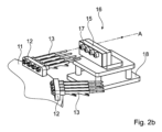
図2bは、この配置を再びより詳細に示す。本例では、複数の合計4本の受けフィンガ13を有する円形ディスク11上に2個の接合ステーション12が示されている。同心の向きで、円形ディスク11の半径方向延長部Aに本質的に平行なこれらとは逆に、押圧ノブ17は処理ステーション16の処理プレート15上に配置されている。この加圧プレート15は、半径方向延長部Aに抗して受けフィンガ13に向かって移動することができるように移動可能であり、したがって、装填された筒に形成作用を及ぼす。
Figure 2b shows this arrangement again in more detail. In this example, two joining
図2cでは、この装置は平面図で示されており、円形ディスク11は、4本の放射状に延びる受けフィンガ13を有する前記ガイドステーション12を有する。受けフィンガの長手方向は、処理プレート15上の押圧ノブ17と同心である。処理プレート15は、受けフィンガの方向にロックプレート18上で変位して受けフィンガに接触圧力を発生することができるようにレール上に取り付けられる。
In FIG. 2c, the device is shown in plan view, with a
図3は、対応する接合ステーション12を詳細に示す。接合ステーション12は、ここでは4つのスリーブ12.2を有し、各スリーブから受けフィンガ13が突出する。受けフィンガ13は、複数の直径部31、32、33を有する。全体として、スリーブから始めて、フィンガ13は第1の直径部33を有する。この第1の直径部上に2つの締付マンドレル35、34が設けられている。この第1の直径部33は、外筒を受けるのに適している。2つの締付マンドレル33、34は、復元力によってこの外筒を保持する役割を果たす。動作中、この例における外筒は、受けフィンガに付与される最後の筒である。
Figure 3 shows in detail the corresponding joining
この第1の直径部には、第1の内筒の内径よりも小さい第2の直径部32が続く。動作中、この第1の内筒は、3ピースのタンポンアプリケータを指す本例で付与される第2の筒である。
This first diameter section is followed by a
この第2の直径部に直接隣接するのは、肩部にわたって先細になり、先端36で終端する第3の直径部である。この最後の直径部31は、第2の内筒を受けるのに適している。
Immediately adjacent to this second diameter is a third diameter that tapers over a shoulder and terminates at a
動作中、第2の外筒は最初にこの最後の直径部31上に滑る。中心直径部32から始めて、テーパ状領域を通って、第2の内筒は、受けフィンガに実質的に解放可能に締め付けられる。
In operation, the second outer barrel is first slid onto this
この動作モードを説明するために、図4a~図4cは、この段階的な装填を示す。図4aは、受けフィンガ13の側面を示す。スリーブ12.2の左側で、接合ステーションが始まる。第1の直径部33は、ブラケットとして形成された2つの締付マンドレル35、34を有するスリーブ12.2から突出している。2つの締付マンドレル35、34は、外筒を受け取った後に外筒が保持されるように、受けフィンガに復元力を及ぼす。
To illustrate this mode of operation, Figures 4a to 4c show this step-by-step loading. Figure 4a shows a side view of the receiving
第1の直径部33は、第2の直径部32が続く停止部で閉じる。この第2の直径部32には、別の停止部及び第3の直径部36へのテーパ状部が続く。受けフィンガは、実質的にテーパ状の先端31で終端する。
The
図4bでは、2つの内筒102、103が既に受けフィンガに付与されている。第2の内筒103は、停止部に当接してテーパ状領域で詰まるように、最後の直径部の上を最初に滑った。第1の内筒102は、第2の直径部の端部まで実質的に延びる最後の直径部の上を滑る。
In FIG. 4b, the two
ここで、図4cは、外筒がこれらの2つの内筒102、103上をどのように滑るかを示す。
Now, Figure 4c shows how the outer cylinder slides over these two
ブラケットとして形成された締付マンドレル35、34は、外筒101に復元力を及ぼす。この場合、第1のブラケット部35は、スリーブ12.2から斜めに突出し、外筒101に接触圧力を及ぼす。第1のブラケット部35と一体の第2のブラケット部34も斜めに突出しており、外筒101を受けるためのステアリングプレートとして機能する。
The clamping
図5は、供給部用に外筒を分離するために使用することができる分離ユニットを示す。花弁形状の遠位口を有する対応する外筒が互いに分離されていることが重要であり、そうでなければ、それらは容易に引っ掛かるおそれがあり、整然と受けフィンガに装填することができない。 Figure 5 shows a separation unit that can be used to separate the barrels for the supply. It is important that the corresponding barrels with petal-shaped distal openings are separated from each other, otherwise they can easily get caught and cannot be loaded into the receiving fingers in an orderly manner.
本例では、筒100はベルト73上を搬送される。駆動ローラ74.1、74.2は、対応するベルトを駆動する。図示の例では、一方のベルトシステムから他方への移送が行われる。ベルト駆動装置77.1、77.2によって駆動される、ゴム引きされた加速ローラ75.1、75.2がこの移送点の上方に設けられる。ここで、外筒100は、第1の速度を有する駆動部70.1、70.2から第2の速度を有する駆動部75.1、75.2を有する領域まで通過する。加速により、インターロックされた外筒が分離される。ベルトは、異なる速度で走行する駆動シャフト71、76によって駆動される。
In this example, the
図6は、同様に受けフィンガを装填するため前記の外筒100も位置合わせする位置合わせユニットを示す。前述のように、外筒100の供給部は、各々が2つのベルト73.1、73.2及び74.3、74.4を有する2つの平行ベルト駆動システムによって達成される。ロボットアーム82及びグリッパ81を有するロボットは、外筒100を把持し、外筒100が実質的に平行であり、すべて同じ方向を向いて置かれるコンベヤ80に外筒を移送する。供給部はさらにロボットシステム(図示せず)内で終了し、ロボットシステムは、例えば、このコンベヤユニット80から一群の外筒を取り外し、それに応じて外筒を装填のために受けフィンガに装填することができる。
Figure 6 shows an alignment unit which also aligns said
図7は、受けフィンガを有する接合ステーション12が処理ステーションと現在どのように動作可能に接続しているかを示す。接合ステーション12は、第1の直径部33上のスリーブ12.2上の外筒101を含む。外筒101に第1の内筒102が挿入され、第2の内筒103も外筒101に挿入されている。
Figure 7 shows how the joining
外筒101は、第1のブラケット部35及び第2のブラケット部34を有するブラケットとして形成された弾性締付マンドレルによって定位置に保持される。
The
処理ステーションは、受けフィンガの長手方向軸に対して同心に形成された押圧ノブ50を含み、押圧ノブは、第2の内筒の近位端に押し入り、第2の内筒103のトランペット形状の近位端全体を作製する円錐形状によって第2の内筒を拡張する。
The processing station includes a
この再成形により、例えば外筒101の口を通って第2の内筒103が3パートタンポンアプリケータから脱落することが防止される。このステップは、本発明によるジョイントを完成させることができる。しかしながら、この接合はまた、いくつかの個々のサブステップにわたって行われ得る。例えば、第1の形成は、特定の第1の接触圧力と共に行われ、第2の形成は、特定の第2の接触圧力と共に行われ得る。各形成作業について、それぞれの圧力ノブを有する別個の処理ステーションを設けることができる。この漸進的な再成形は、タンポンアプリケータの近位端の所望のトランペット形状の拡張を得るために必要な回数だけ繰り返すことができる。本発明による装置は、いくつかの中空筒からのタンポンアプリケータを省スペースかつ効率的な方法で高速スループットで接合するために使用することができる。本発明による装置は、3パートタンポンアプリケータを、延在して定位置にロックされた伸縮式プランジャと接合するのに特に適している。
This reshaping prevents the second
Claims (19)
a.1つの外筒(101)及び1つの第1の内筒(102)をそれぞれ受けるための少なくとも1つの受けフィンガ(13.1、13.2)を有する少なくとも1つの接合ステーション(12)と、
b.前記少なくとも1つの受けフィンガに少なくとも1つの第1の内筒(102)を装填するための第1の内筒供給部と、
c.前記少なくとも1つの受けフィンガ(13.1、13.2)に少なくとも1つの外筒(101)を装填するための外筒供給部と、
d.前記少なくとも1つの外筒(101)を前記少なくとも1つの第1の内筒(102)に接合するための第1の処理ステーション(16)と、
を備える装置において、
前記少なくとも1つの接合ステーション(12)が、円形ディスク(11)上に放射状に配置されている
ことを特徴とする、装置。 1. An apparatus for joining a multi-part tampon applicator , said multi-part tampon applicator comprising an outer barrel (101) and a first inner barrel (102), said apparatus comprising:
a. at least one joining station (12) having at least one receiving finger (13.1, 13.2) for receiving one outer cylinder (101) and one first inner cylinder (102), respectively;
b. a first liner supply for loading at least one first liner (102) onto said at least one receiving finger;
c. a barrel supply for loading at least one barrel (101) onto said at least one receiving finger (13.1, 13.2);
d. a first processing station (16) for joining said at least one outer cylinder (101) to said at least one first inner cylinder (102);
In an apparatus comprising:
10. An apparatus according to claim 9, wherein said at least one joining station (12) is arranged radially on a circular disk (11).
a.前記少なくとも1つの受けフィンガに少なくとも1つの第2の内筒を装填するための第2の内筒供給部
をさらに備え、
前記第1の処理ステーションが、前記少なくとも1つの第1の内筒を前記少なくとも1つの第2の内筒に接合するようになっている、
請求項1に記載の装置。 the multi-part tampon applicator includes a second inner barrel, the device comprising:
a. a second liner supply for loading at least one second liner into said at least one receiving finger;
the first processing station is adapted to join the at least one first inner cylinder to the at least one second inner cylinder;
2. The apparatus of claim 1.
第2の処理ステーションが、受けフィンガに受けられた外筒、第1の内筒、及び/若しくは第2の内筒を再成形するように設計されている、又は
前記第1の処理ステーション及び前記第2の処理ステーションが、受けフィンガに受けられた外筒、第1の内筒、及び/若しくは第2の内筒を再成形するように設計されている、請求項1~5のいずれか一項に記載の装置。 the first processing station is designed to reshape the outer cylinder, the first inner cylinder, and/ or the second inner cylinder received in the receiving fingers, or
the second processing station is designed to reshape the outer cylinder, the first inner cylinder, and/or the second inner cylinder received in the receiving fingers, or
The apparatus according to any one of claims 1 to 5, wherein the first processing station and the second processing station are designed to reshape the outer cylinder, the first inner cylinder, and/or the second inner cylinder received in the receiving fingers .
a.接合ステーションを第1の内筒供給部と位置合わせするステップと、
b.前記接合ステーションの第1の受けフィンガに第1の内筒を装填するステップと、
c.前記接合ステーションを外筒供給部又は第2の内筒供給部と位置合わせするステップと、
d.前記接合ステーションの前記受けフィンガに外筒又は第2の内筒を装填するステップと、
を含む方法において、
円形ディスク(11)上に放射状に配置された前記接合ステーション(12)の前記位置合わせが、前記円形ディスクの円回転によってもたらされる
ことを特徴とする、方法。 1. A method for joining a multi-part tampon applicator , comprising:
a. aligning a bonding station with a first inner cylinder supply;
b. loading a first inner cylinder into a first receiving finger of said joining station;
c. aligning the bonding station with an outer cylinder supply or a second inner cylinder supply;
d. loading an outer cylinder or a second inner cylinder into the receiving finger of the joining station;
In a method comprising:
2. A method according to claim 1, characterised in that the alignment of the joining stations (12) arranged radially on a circular disk (11) is effected by a circular rotation of the circular disk.
をさらに含む、請求項11に記載の方法。 a. aligning the bonding station with a forming station for forming the first inner barrel and/or the second inner barrel by applying heat and pressure;
The method of claim 11 further comprising :
Applications Claiming Priority (3)
| Application Number | Priority Date | Filing Date | Title |
|---|---|---|---|
| CH00412/20A CH717298A1 (en) | 2020-04-06 | 2020-04-06 | Device and method for joining multi-part tampon applicators. |
| CH412/20 | 2020-04-06 | ||
| PCT/EP2021/058822 WO2021204732A1 (en) | 2020-04-06 | 2021-04-04 | Device and method for joining multi-part tampon applicators |
Publications (2)
| Publication Number | Publication Date |
|---|---|
| JP2023519129A JP2023519129A (en) | 2023-05-10 |
| JP7597823B2 true JP7597823B2 (en) | 2024-12-10 |
Family
ID=73020010
Family Applications (1)
| Application Number | Title | Priority Date | Filing Date |
|---|---|---|---|
| JP2022551655A Active JP7597823B2 (en) | 2020-04-06 | 2021-04-04 | Apparatus and method for joining multi-part tampon applicators - Patents.com |
Country Status (14)
| Country | Link |
|---|---|
| US (1) | US12465527B2 (en) |
| EP (1) | EP4132442B1 (en) |
| JP (1) | JP7597823B2 (en) |
| KR (1) | KR20220163958A (en) |
| CN (1) | CN115515544B (en) |
| AU (1) | AU2021253122B2 (en) |
| CH (1) | CH717298A1 (en) |
| CO (1) | CO2022015064A2 (en) |
| DK (1) | DK4132442T3 (en) |
| IL (1) | IL297005A (en) |
| MX (1) | MX2022009953A (en) |
| SI (1) | SI4132442T1 (en) |
| WO (1) | WO2021204732A1 (en) |
| ZA (1) | ZA202210025B (en) |
Citations (3)
| Publication number | Priority date | Publication date | Assignee | Title |
|---|---|---|---|---|
| WO2010013605A1 (en) | 2008-07-31 | 2010-02-04 | ユニ・チャーム株式会社 | Device for producing tampons and method for producing tampons |
| JP2010081989A (en) | 2008-09-29 | 2010-04-15 | Uni Charm Corp | Apparatus and method for producing tampon |
| WO2020052999A1 (en) | 2018-09-10 | 2020-03-19 | Ruggli Projects Ag | Device and method for loading tampon applicators with tampons |
Family Cites Families (11)
| Publication number | Priority date | Publication date | Assignee | Title |
|---|---|---|---|---|
| US2624078A (en) * | 1947-08-08 | 1953-01-06 | Sanitary Tampon Corp | Machine for compressing and assembling tampons |
| US3568577A (en) * | 1967-12-12 | 1971-03-09 | Joseph A Voss | Applicators for catamenial devices |
| US4006515A (en) * | 1974-12-10 | 1977-02-08 | The Procter & Gamble Company | Apparatus for forming tampons and assembling same in inserters |
| RU2044530C1 (en) | 1993-09-28 | 1995-09-27 | Предприятие "Альберт" | Device for insertion of menstrual tampon |
| US6343558B1 (en) * | 1998-05-01 | 2002-02-05 | Daniel R. Shepard | Shuttle apparatus for high-speed lacing of an article |
| US6923789B2 (en) * | 2002-02-22 | 2005-08-02 | Playtex Products, Inc. | Multiple-component tampon applicator |
| DE102010055155A1 (en) * | 2010-12-15 | 2012-06-21 | Khs Corpoplast Gmbh | Method for plasma treatment of workpieces and workpiece with gas barrier layer |
| US8458882B2 (en) * | 2011-02-10 | 2013-06-11 | Kimberly-Clark Worldwide, Inc. | Method for assembling a tampon applicator |
| JP5715993B2 (en) * | 2012-09-12 | 2015-05-13 | ユニ・チャーム株式会社 | Tampon applicator |
| AU2017366808A1 (en) * | 2016-11-30 | 2019-06-06 | Kimberly-Clark Worldwide, Inc. | Molding thermoplastic injection-molded and flushable materials |
| CH715069B1 (en) | 2018-06-05 | 2025-09-30 | Ruggli Ag | Conveying device and method for conveying tampon applicators. |
-
2020
- 2020-04-06 CH CH00412/20A patent/CH717298A1/en unknown
-
2021
- 2021-04-04 CN CN202180021842.3A patent/CN115515544B/en active Active
- 2021-04-04 IL IL297005A patent/IL297005A/en unknown
- 2021-04-04 AU AU2021253122A patent/AU2021253122B2/en active Active
- 2021-04-04 SI SI202130176T patent/SI4132442T1/en unknown
- 2021-04-04 US US17/916,859 patent/US12465527B2/en active Active
- 2021-04-04 JP JP2022551655A patent/JP7597823B2/en active Active
- 2021-04-04 DK DK21716427.6T patent/DK4132442T3/en active
- 2021-04-04 WO PCT/EP2021/058822 patent/WO2021204732A1/en not_active Ceased
- 2021-04-04 MX MX2022009953A patent/MX2022009953A/en unknown
- 2021-04-04 KR KR1020227033886A patent/KR20220163958A/en not_active Ceased
- 2021-04-04 EP EP21716427.6A patent/EP4132442B1/en active Active
-
2022
- 2022-09-08 ZA ZA2022/10025A patent/ZA202210025B/en unknown
- 2022-10-21 CO CONC2022/0015064A patent/CO2022015064A2/en unknown
Patent Citations (3)
| Publication number | Priority date | Publication date | Assignee | Title |
|---|---|---|---|---|
| WO2010013605A1 (en) | 2008-07-31 | 2010-02-04 | ユニ・チャーム株式会社 | Device for producing tampons and method for producing tampons |
| JP2010081989A (en) | 2008-09-29 | 2010-04-15 | Uni Charm Corp | Apparatus and method for producing tampon |
| WO2020052999A1 (en) | 2018-09-10 | 2020-03-19 | Ruggli Projects Ag | Device and method for loading tampon applicators with tampons |
Also Published As
| Publication number | Publication date |
|---|---|
| WO2021204732A1 (en) | 2021-10-14 |
| CO2022015064A2 (en) | 2022-12-30 |
| CN115515544A (en) | 2022-12-23 |
| DK4132442T3 (en) | 2024-07-29 |
| MX2022009953A (en) | 2022-11-30 |
| ZA202210025B (en) | 2024-01-31 |
| AU2021253122B2 (en) | 2025-10-23 |
| US12465527B2 (en) | 2025-11-11 |
| SI4132442T1 (en) | 2024-09-30 |
| JP2023519129A (en) | 2023-05-10 |
| US20230157902A1 (en) | 2023-05-25 |
| CH717298A1 (en) | 2021-10-15 |
| IL297005A (en) | 2022-12-01 |
| EP4132442A1 (en) | 2023-02-15 |
| CN115515544B (en) | 2025-04-18 |
| EP4132442B1 (en) | 2024-05-29 |
| AU2021253122A1 (en) | 2022-09-29 |
| BR112022016329A2 (en) | 2022-10-04 |
| KR20220163958A (en) | 2022-12-12 |
Similar Documents
| Publication | Publication Date | Title |
|---|---|---|
| US6936211B2 (en) | Tampon applicator having outwardly flared rim | |
| AU2001266901A1 (en) | Tampon applicator having outwardly flared rim | |
| US20220185598A1 (en) | Transport unit for transporting aerosol cans and method for operating a transport unit | |
| JP7597823B2 (en) | Apparatus and method for joining multi-part tampon applicators - Patents.com | |
| USRE30410E (en) | Apparatus for loading prophylactic devices on test apparatus | |
| JPS61124370A (en) | Bobbin exchange unit for machine in tobacco processing industry | |
| JPH0135660B2 (en) | ||
| JPH0124622B2 (en) | ||
| US5424015A (en) | Method and device for manufacturing rubber bend pipe | |
| US6959739B2 (en) | Tube-filling machine and a filling method in such a machine | |
| US5597433A (en) | Method and apparatus for manufacturing plastic canisters | |
| US3513755A (en) | Nested plastic bag production process and apparatus | |
| RU2809575C1 (en) | Device and method for connecting multi-component tampon applicators | |
| KR102796210B1 (en) | Device and method for placing a tampon on a tampon applicator | |
| US4241848A (en) | Container processing apparatus | |
| US4104013A (en) | Tampon ejector tube and apparatus | |
| JPH0270425A (en) | Transferring device of composing member of tire | |
| BR112022016329B1 (en) | DEVICE AND METHOD FOR JOINING MULTIPLE-PART ABSORBENT APPLICATORS | |
| JP2023505903A (en) | Method for assembling an aerosol-generating article | |
| EP0103027A1 (en) | Method and apparatus for manufacturing metal can | |
| EP0004971A1 (en) | Equipment and method for forming cylindrical blanks | |
| CN104995018B (en) | For a kind of apparatus and method for the annular gum filler for forming tire bead | |
| US3391803A (en) | Apparatus for loading prophylactic devices on test apparatus | |
| JPH07112583B2 (en) | Flexible wire forming and feeding device | |
| JPH0414186Y2 (en) |
Legal Events
| Date | Code | Title | Description |
|---|---|---|---|
| A621 | Written request for application examination |
Free format text: JAPANESE INTERMEDIATE CODE: A621 Effective date: 20240213 |
|
| A711 | Notification of change in applicant |
Free format text: JAPANESE INTERMEDIATE CODE: A712 Effective date: 20240531 |
|
| A977 | Report on retrieval |
Free format text: JAPANESE INTERMEDIATE CODE: A971007 Effective date: 20241008 |
|
| A131 | Notification of reasons for refusal |
Free format text: JAPANESE INTERMEDIATE CODE: A131 Effective date: 20241029 |
|
| A521 | Request for written amendment filed |
Free format text: JAPANESE INTERMEDIATE CODE: A523 Effective date: 20241111 |
|
| TRDD | Decision of grant or rejection written | ||
| A01 | Written decision to grant a patent or to grant a registration (utility model) |
Free format text: JAPANESE INTERMEDIATE CODE: A01 Effective date: 20241126 |
|
| A61 | First payment of annual fees (during grant procedure) |
Free format text: JAPANESE INTERMEDIATE CODE: A61 Effective date: 20241128 |
|
| R150 | Certificate of patent or registration of utility model |
Ref document number: 7597823 Country of ref document: JP Free format text: JAPANESE INTERMEDIATE CODE: R150 |