JP7601192B2 - Liquid ejection device - Google Patents
Liquid ejection device Download PDFInfo
- Publication number
- JP7601192B2 JP7601192B2 JP2023198700A JP2023198700A JP7601192B2 JP 7601192 B2 JP7601192 B2 JP 7601192B2 JP 2023198700 A JP2023198700 A JP 2023198700A JP 2023198700 A JP2023198700 A JP 2023198700A JP 7601192 B2 JP7601192 B2 JP 7601192B2
- Authority
- JP
- Japan
- Prior art keywords
- liquid
- head
- sub
- tank
- subtank
- Prior art date
- Legal status (The legal status is an assumption and is not a legal conclusion. Google has not performed a legal analysis and makes no representation as to the accuracy of the status listed.)
- Active
Links
Images





Classifications
-
- B—PERFORMING OPERATIONS; TRANSPORTING
- B41—PRINTING; LINING MACHINES; TYPEWRITERS; STAMPS
- B41J—TYPEWRITERS; SELECTIVE PRINTING MECHANISMS, i.e. MECHANISMS PRINTING OTHERWISE THAN FROM A FORME; CORRECTION OF TYPOGRAPHICAL ERRORS
- B41J2/00—Typewriters or selective printing mechanisms characterised by the printing or marking process for which they are designed
- B41J2/005—Typewriters or selective printing mechanisms characterised by the printing or marking process for which they are designed characterised by bringing liquid or particles selectively into contact with a printing material
- B41J2/01—Ink jet
- B41J2/17—Ink jet characterised by ink handling
- B41J2/175—Ink supply systems ; Circuit parts therefor
- B41J2/17566—Ink level or ink residue control
-
- B—PERFORMING OPERATIONS; TRANSPORTING
- B41—PRINTING; LINING MACHINES; TYPEWRITERS; STAMPS
- B41J—TYPEWRITERS; SELECTIVE PRINTING MECHANISMS, i.e. MECHANISMS PRINTING OTHERWISE THAN FROM A FORME; CORRECTION OF TYPOGRAPHICAL ERRORS
- B41J2/00—Typewriters or selective printing mechanisms characterised by the printing or marking process for which they are designed
- B41J2/005—Typewriters or selective printing mechanisms characterised by the printing or marking process for which they are designed characterised by bringing liquid or particles selectively into contact with a printing material
- B41J2/01—Ink jet
- B41J2/17—Ink jet characterised by ink handling
- B41J2/175—Ink supply systems ; Circuit parts therefor
- B41J2/17503—Ink cartridges
- B41J2/17513—Inner structure
-
- B—PERFORMING OPERATIONS; TRANSPORTING
- B41—PRINTING; LINING MACHINES; TYPEWRITERS; STAMPS
- B41J—TYPEWRITERS; SELECTIVE PRINTING MECHANISMS, i.e. MECHANISMS PRINTING OTHERWISE THAN FROM A FORME; CORRECTION OF TYPOGRAPHICAL ERRORS
- B41J2/00—Typewriters or selective printing mechanisms characterised by the printing or marking process for which they are designed
- B41J2/005—Typewriters or selective printing mechanisms characterised by the printing or marking process for which they are designed characterised by bringing liquid or particles selectively into contact with a printing material
- B41J2/01—Ink jet
- B41J2/17—Ink jet characterised by ink handling
- B41J2/175—Ink supply systems ; Circuit parts therefor
- B41J2/17503—Ink cartridges
- B41J2/1752—Mounting within the printer
- B41J2/17523—Ink connection
-
- B—PERFORMING OPERATIONS; TRANSPORTING
- B41—PRINTING; LINING MACHINES; TYPEWRITERS; STAMPS
- B41J—TYPEWRITERS; SELECTIVE PRINTING MECHANISMS, i.e. MECHANISMS PRINTING OTHERWISE THAN FROM A FORME; CORRECTION OF TYPOGRAPHICAL ERRORS
- B41J2/00—Typewriters or selective printing mechanisms characterised by the printing or marking process for which they are designed
- B41J2/005—Typewriters or selective printing mechanisms characterised by the printing or marking process for which they are designed characterised by bringing liquid or particles selectively into contact with a printing material
- B41J2/01—Ink jet
- B41J2/17—Ink jet characterised by ink handling
- B41J2/175—Ink supply systems ; Circuit parts therefor
- B41J2/17503—Ink cartridges
- B41J2/17553—Outer structure
-
- B—PERFORMING OPERATIONS; TRANSPORTING
- B41—PRINTING; LINING MACHINES; TYPEWRITERS; STAMPS
- B41J—TYPEWRITERS; SELECTIVE PRINTING MECHANISMS, i.e. MECHANISMS PRINTING OTHERWISE THAN FROM A FORME; CORRECTION OF TYPOGRAPHICAL ERRORS
- B41J2/00—Typewriters or selective printing mechanisms characterised by the printing or marking process for which they are designed
- B41J2/005—Typewriters or selective printing mechanisms characterised by the printing or marking process for which they are designed characterised by bringing liquid or particles selectively into contact with a printing material
- B41J2/01—Ink jet
- B41J2/17—Ink jet characterised by ink handling
- B41J2/175—Ink supply systems ; Circuit parts therefor
- B41J2/17566—Ink level or ink residue control
- B41J2002/17579—Measuring electrical impedance for ink level indication
-
- B—PERFORMING OPERATIONS; TRANSPORTING
- B41—PRINTING; LINING MACHINES; TYPEWRITERS; STAMPS
- B41J—TYPEWRITERS; SELECTIVE PRINTING MECHANISMS, i.e. MECHANISMS PRINTING OTHERWISE THAN FROM A FORME; CORRECTION OF TYPOGRAPHICAL ERRORS
- B41J25/00—Actions or mechanisms not otherwise provided for
- B41J2025/008—Actions or mechanisms not otherwise provided for comprising a plurality of print heads placed around a drum
Landscapes
- Ink Jet (AREA)
Description
本発明は液体を吐出する装置に関する。 The present invention relates to a device for discharging liquid.
シート材を搬送するドラムの周りに複数の液体を吐出するヘッドを傾けて配置し、ヘッドに供給する液体を一時的に貯留するサブタンク(液体収容容器)を備える印刷装置などの液体を吐出する装置がある。 There are devices that eject liquids, such as printing devices, that have heads that eject multiple liquids arranged at an angle around a drum that transports sheet material, and that are equipped with subtanks (liquid storage containers) that temporarily store the liquid to be supplied to the heads.
従来、ヘッドの傾きに応じてサブタンクの高さを異ならせることで、ヘッドとサブタンクとの間の水頭差をほぼ同じにして、ヘッドにかかる負圧のばらつきを低減するものが知られている(特許文献1)。 Conventionally, a method has been known in which the height of the sub-tank is varied according to the inclination of the head, thereby making the head head difference between the head and the sub-tank approximately the same and reducing the variation in the negative pressure applied to the head (Patent Document 1).
上述したように、ヘッドに供給する液体を一時的に貯留するサブタンクをヘッドと同様に傾けて配置すると、サブタンクの傾きの度合いによってタンク内の液面高さが異なることになる。そのため、ヘッドとサブタンクとの間での水頭差にばらつきが生じ、各ヘッド間で負圧のばらつきが生じるという課題がある。 As mentioned above, if the subtank that temporarily stores the liquid to be supplied to the head is tilted in the same way as the head, the liquid level in the tank will differ depending on the degree of tilt of the subtank. This causes variation in the head difference between the head and the subtank, which creates the problem of variation in negative pressure between each head.
本発明は上記の課題に鑑みてなされたものであり、ヘッド間での負圧のばらつきを低減することを目的とする。 The present invention was made in consideration of the above problems, and aims to reduce the variation in negative pressure between heads.
上記の課題を解決するため、本発明の請求項1に係る液体を吐出する装置は、
液体を吐出する複数のヘッドと、
前記複数のヘッドにそれぞれ供給する液体を収容する複数のサブタンクと、を備え、
前記複数のヘッド及び前記複数の前記サブタンクは鉛直方向に対して傾いて配置され、
前記サブタンクは、液体残量の上限位置を検出する上限検出手段と、液体残量の下限位置を検出する下限検出手段とを有し、
傾き角度が相対的に大きい前記ヘッドの前記サブタンクは、傾き角度が相対的に小さい前記ヘッドの前記サブタンクに比べて、前記上限位置と前記下限位置との距離が大きい
構成とした。
In order to solve the above problems, a liquid ejection device according to a first aspect of the present invention comprises:
A plurality of heads for ejecting liquid;
a plurality of sub-tanks each containing liquid to be supplied to each of the plurality of heads;
the plurality of heads and the plurality of sub-tanks are disposed at an angle with respect to a vertical direction,
the sub-tank has an upper limit detection means for detecting an upper limit position of the remaining amount of liquid, and a lower limit detection means for detecting a lower limit position of the remaining amount of liquid,
The sub-tank of the head having a relatively large inclination angle has a larger distance between the upper limit position and the lower limit position than the sub-tank of the head having a relatively small inclination angle.
The composition was as follows.
本発明によれば、ヘッド間での負圧のばらつきを低減することができる。 The present invention can reduce the variation in negative pressure between heads.
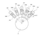
以下、本発明の実施の形態について添付図面を参照して説明する。本発明の第1実施形態に係る液体を吐出する装置としての印刷装置について図1及び図2を参照して説明する。図1は同印刷装置の概略説明図、図2は同印刷装置の印刷部30の要部説明図である。
Embodiments of the present invention will be described below with reference to the accompanying drawings. A printing device as a device for ejecting liquid according to a first embodiment of the present invention will be described with reference to Figs. 1 and 2. Fig. 1 is a schematic diagram of the printing device, and Fig. 2 is a diagram of the main parts of the
印刷装置1は、シート材Pを搬入する搬入部10と、前処理部20と、印刷部30と、乾燥部40と、搬出部50と、反転機構部60を備えている。印刷装置1は、搬入部10から搬入(供給)されるシート材Pに対し、前処理手段である前処理部20で必要に応じて前処理液を付与(塗布)し、印刷部30で液体を付与して所要の印刷を行い、乾燥部40でシート材Pに付着した液体を乾燥させた後、シート材Pを搬出部50に排出する。
The
搬入部10は、複数のシート材Pを収容する搬入トレイ11(下段搬入トレイ11A、上段搬入トレイ11B)と、搬入トレイ11からシート材Pを1枚ずつ分離して送り出す給送装置12(12A、12B)とを備え、シート材Pを前処理部20に供給する。
The
前処理部20は、例えばインクを凝集させ、裏写りを防止する作用効果を有する処理液をシート材Pの印刷面に付与する処理液付与手段である塗布部21などを備えている。
The
印刷部30は、シート材Pを周面に担持して回転する担持部材(回転体)であるドラム31と、ドラム31に担持されたシート材Pに向けて液体を吐出する液体吐出部32を備えている。
The
また、印刷部30は、前処理部20から送り込まれたシート材Pを受け取ってドラム31との間でシート材Pを渡す渡し胴34と、ドラム31によって搬送されたシート材Pを受け取って反転機構部60に渡す受け渡し胴35を備えている。
The
前処理部20から印刷部30へ搬送されてきたシート材Pは、渡し胴34に設けられた把持手段(シートグリッパ)によって先端が把持され、渡し胴34の回転に伴って搬送される。渡し胴34により搬送されたシート材Pは、ドラム31との対向位置でドラム31へ受け渡される。
The sheet material P transported from the
ドラム31の表面にも把持手段(シートグリッパ)が設けられており、シート材Pの先端が把持手段(シートグリッパ)によって把持される。ドラム31の表面には、複数の吸引穴が分散して形成され、吸引手段によってドラム31の所要の吸引穴から内側へ向かう吸い込み気流を発生させる。
A gripping means (sheet gripper) is also provided on the surface of the
そして、渡し胴34からドラム31へ受け渡されたシート材Pは、シートグリッパによって先端が把持されるとともに、吸引手段による吸い込み気流によってドラム31上に吸着担持され、ドラム31の回転に伴って搬送される。
Then, the sheet material P transferred from the
液体吐出部32は、液体吐出手段である吐出ユニット33(33A~3E)を備えている。例えば、吐出ユニット33Aはブラック(K)、吐出ユニット33Bはシアン(C)の液体を、吐出ユニット33Cはマゼンタ(M)の液体を、吐出ユニット33Dはイエロー(Y)の液体をそれぞれ吐出する。吐出ユニット33Eは、その他の白色、金色(銀色)などの特殊な液体の吐出を行う吐出ユニットとして使用している。
The
液体吐出部32の各吐出ユニット33(33A~33E)は、図2に示すように、液体を吐出するヘッドユニット(ヘッドモジュール、ヘッドアレイ)200と、ヘッドユニット200に供給する液体を貯留するサブタンク(液体収容容器)300(300A~300E)とを備えている。
As shown in FIG. 2, each ejection unit 33 (33A to 33E) of the
ここで、各吐出ユニット33A~33Eは、いずれも、ドラム31の中心に対して法線方向に配置している。そして、本実施形態では、吐出ユニット33Cをドラム31の中心を通る垂線方向(鉛直方向)に配置し、吐出ユニット33A,33B、33D、33Eは、吐出ユニット33Cを基準として所定の角度θずつ傾けて配置している。
Here, each of the
液体吐出部32の各吐出ユニット33は、印刷情報に応じた駆動信号によりそれぞれ吐出動作が制御される。ドラム31に担持されたシート材Pが液体吐出部32との対向領域を通過するときに、吐出ユニット33から各色の液体が吐出され、当該印刷情報に応じた画像が印刷される。
The ejection operation of each
反転機構部60は、受け渡し胴35から渡されたシート材Pに対して両面印刷をおこなうときに、スイッチバック方式で、シート材Pを反転する機構であり、反転されたシート材Pは印刷部30の搬送経路61を通じて渡し胴34よりも上流側に逆送される。
The
乾燥部40は、印刷部30でシート材P上に付着した液体を乾燥させる。これにより液体中の水分等の液分が蒸発し、シート材P上に液体中に含まれる着色剤が定着し、また、シート材Pのカールが抑制される。
The
搬出部50は、複数のシート材Pが積載される搬出トレイ51を備えている。乾燥部40から搬送されてくるシート材Pは、搬出トレイ51上に順次積み重ねられて保持される。
The
次に、吐出ユニットを構成しているヘッドユニット(ヘッドモジュール、ヘッドアレイ)の一例について図3を参照して説明する。図3は同ヘッドユニットをノズル面側から見た平面説明図である。 Next, an example of a head unit (head module, head array) that constitutes a discharge unit will be described with reference to Figure 3. Figure 3 is a plan view of the head unit as seen from the nozzle surface side.
ヘッドユニット200は、液体を吐出する複数のヘッド100を千鳥状にベース部材202に並べて配置したものである。
The
各ヘッド100は、液体を吐出する複数のノズル104が配列されたノズル列を複数列(ここでは4列を例にしているが、限定されない。)有している。
Each
本実施形態では、ヘッド100を千鳥状に配置しているので、各列のヘッド100をドラム31の中心に対して法線方向に配置し、ノズル面(吐出面)101が接線方向になるように傾けている。
In this embodiment, the
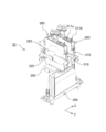
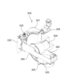
次に、吐出ユニット及びサブタンクの一例について図4ないし図6を参照して説明する。図4は吐出ユニットの外観斜視説明図、図5は同サブタンクの正面説明図、図6は同サブタンクの部分断面斜視説明図である。 Next, an example of a discharge unit and a subtank will be described with reference to Figs. 4 to 6. Fig. 4 is an explanatory perspective view of the appearance of the discharge unit, Fig. 5 is an explanatory front view of the subtank, and Fig. 6 is an explanatory perspective view of a part of the subtank in cross section.
吐出ユニット33は、固定部材350に、ヘッドユニット200と、2つのサブタンク300を備えている。2つのサブタンク300は、ヘッドユニット200のヘッド配列方向に並べて配置されている。
The
サブタンク300は、液体を収容する液体収容部302を構成する一面側が開口したタンク本体301を有している。タンク本体301の開口部は可撓性フィルムなどの可撓性膜303で封止している。
The
液体収容部302内には、可撓性膜303を面外方向に付勢する弾性部材(例えばバネなど)304が配置され、液体収容部302内の液体残量が減少することにより、弾性部材304による付勢力によって可撓性膜303が面外方向に押されて負圧が形成される。
An elastic member (e.g., a spring) 304 is disposed within the
タンク本体301の下部には、液体供給口305が設けられている。液体供給口305には、着脱自在の連結部を連結することにより、メインタンクから連結部に圧送された液体が送り込まれ、液体収容部302へ補充される。メインタンクとサブタンク300との間にはメインタンクからサブタンク300に液体を圧送する送液ポンプ(送液部)が構成されている。液体供給口305には、送液ポンプによりメインタンクから液体が送り込まれる。
A
タンク本体301上部には、液体排出口306が設けられている。液体排出口306は、サブタンク300からヘッド100に供給する液体を負圧の発生により排出する。液体排出口306と各ヘッド100に液体を分配供給するマニホールドとをチューブなどにより接続することにより、サブタンク300から排出された液体が各ヘッド100に分配供給される。
A
タンク本体301上部には、サブタンク300内を大気に開放する大気開放手段である大気開放機構310を設けている。大気開放機構310を開状態にすることで液体収容部302が大気に開放され(負圧が解消され)、大気開放機構310を開状態にすることで液体収容部302は密閉状態になり負圧を発生可能となる。
An
タンク本体301の上部には、液体収容部302内の液体残量が所定量以下(エンド又はニアーエンド:併せて、「エンド状態」という。)になったことを検知するための2本の検知電極311(311a、311b)を有している。検知電極311a、311b間が液体を通じて導通状態にあるか、非導通状態にあるかでエンド状態か否かを判別することができる。
The upper part of the
次に、サブタンクの残量検知手段について図7及び図8を参照して説明する。図7は同サブタンクの外観斜視説明図、図8は同サブタンクの部分分解斜視説明図である。 Next, the remaining amount detection means of the subtank will be described with reference to Figures 7 and 8. Figure 7 is an explanatory perspective view of the exterior of the subtank, and Figure 8 is an explanatory partial exploded perspective view of the subtank.
タンク本体301の可撓性膜303の外側には、一端部側を軸321で揺動可能に支持されたフィラからなる変位部材320を有している。
The
変位部材320は、スプリングなどの押し付け手段によってタンク本体301側に向けて付勢され、可撓性膜303の外面側に押し付けられている。これにより、液体収容部302の液体残量に応じて変位する可撓性膜303の動きに連動(追従)して変位部材320が変位する。
The
一方、タンク本体301の固定部301aに取り付けたセンサ保持部材(センサブラケット)330、330には、それぞれ、変位部材320を検知する上限検出手段としての上限センサ331と、変位部材320を検知する下限検出手段としての下限センサ332が保持されている。
On the other hand, the sensor holding members (sensor brackets) 330, 330 attached to the fixed
上限センサ331は、予め定めた液体残量の上限位置(フル位置)に対応する位置に変位部材320が変位したときに変位部材320を検知する。下限センサ332は、予め定めた液体残量の下限位置(エンプティ位置)に対応する位置に変位部材320が変位したときに変位部材320を検知する。
The
上限センサ331及び下限センサ332をそれぞれ保持する検出手段保持部材であるセンサ保持部材330、330は、センサ保持部材330に設けた長孔336を介して締結部材335を固定部301aに締結することで、固定部301aに固定されている。
The
ここで、上限センサ331及び下限センサ332を保持するセンサ保持部材330は、長孔336によって変位部材320の変位方向Dにおいて固定部301aに対する固定位置を調整することができる。つまり、上限センサ331及び下限センサ332による変位部材320の検出位置を調整することができる。
The
これにより、上限センサ331が変位部材320を検知する上限検出位置、下限センサ332が変位部材320を検知する下限検出位置を変更(調整)することができる。
This allows the upper limit detection position at which the
次に、複数の吐出ユニット33における上限センサ及び下限センサの取付け位置(検出位置)について図9を参照して説明する。図9は同説明に供する図7を矢印F方向から見た説明図である。
Next, the mounting positions (detection positions) of the upper limit sensor and the lower limit sensor in the
サブタンク300の変位部材320は、図9において、液体収容部302内の液体残量が減少するに従って矢印D1方向に変位し、液体残量が増加するに従って矢印D2方向に変位する。
In FIG. 9, the
ここで、図9(a)に示すように、垂線方向に配置された吐出ユニット33Cのサブタンク300Cの上限センサ331、下限センサ332は、検出位置f1、e1で変位部材320を検知する。
As shown in FIG. 9(a), the
これに対して、吐出ユニット33Bは、吐出ユニット33Cに対して角度θだけ傾けて配置している。そこで、サブタンク300Bの上限センサ331、下限センサ332は、図9(b)に示すように、吐出ユニット33Cのサブタンク300Aの検出位置f1、e1よりも液体残量が多くなる検出位置f2、e2で変位部材320を検知する。
In contrast,
さらに、吐出ユニット33Aは、吐出ユニット33Bに対して更に角度θだけ傾けて配置している。そこで、サブタンク300Aの上限センサ331、下限センサ332は、図9(c)に示すように、吐出ユニット33Bのサブタンク330Bの検出位置f2、e2よりも液体残量が多くなる検出位置f3、e3で変位部材320を検知する。
Furthermore,
次に、サブタンク300に対する液体の補給動作の制御の一例について図10のフロー図を参照して説明する。
Next, an example of control of the liquid refill operation for the
サブタンク300に対して、例えば大気開放状態にした後検知電極311a、311b間が液体を検知するまで送液して満タンにした状態で、後述する送液ポンプ561を逆転駆動して、後述するメインタンク500に液体を戻す逆送液を行う(ステップS1、以下単に「S1」などという。)。
After opening the
そして、上限センサ331が変位部材(図10ではフィラと表記)320を検知したか否かを判別し(S2)、上限センサ331が変位部材320を検知したときから所定量逆送後、送液ポンプ561を停止する(S3)。
Then, it is determined whether the
次いで、下限センサ332が変位部材320を検知したか否かを判別し(S4)、下限センサ332が変位部材320を検知したときには、送液ポンプ561を正転して(S5)、サブタンク300に液体を送液(補給)する。
Next, it is determined whether the
そして、上限センサ331が変位部材320を検知するまで補給したか否かを判別し(S6)、上限センサ331が変位部材320を検知した時には送液ポンプ561を停止し、ステップS4に戻る。
Then, it is determined whether or not the liquid has been replenished until the
また、下限センサ332が変位部材320を検知していないときには、装置停止などの動作終了か否かを判別し(S8)、動作終了までステップ4に戻る処理を繰り返す。
In addition, when the
このように、上限センサ331が変位部材32を検知する上限位置と下限センサ332が変位部材320を検知する下限位置の間を制御範囲として、サブタンク320に対する送液を制御する。この制御範囲は、サブタンク320の適正負圧範囲となる。
In this way, the liquid supply to the
次に、本実施形態の作用について図11及び図12も参照して説明する。図11はサブタンクの排出量と変位部材の変位量及び圧力の変化の関係(排水特性)の一例を示す説明図、図12は図11の位置X0、X1におけるサブタンクの変位部材の状態を説明する説明図である。 Next, the operation of this embodiment will be described with reference to Figures 11 and 12. Figure 11 is an explanatory diagram showing an example of the relationship between the discharge amount of the subtank and the displacement amount and pressure change of the displacement member (drainage characteristics), and Figure 12 is an explanatory diagram explaining the state of the displacement member of the subtank at positions X0 and X1 in Figure 11.
前述した図2を参照して、各吐出ユニット33A~33Eは、いずれも、ドラム31の中心に対して法線方向に配置し、吐出ユニット33A,33B、33D、33Eは、吐出ユニット33Cを基準として所定の角度θずつ傾けて配置している。
Referring to FIG. 2, each of the
そして、吐出ユニット33は、ヘッドユニット200のヘッド100のノズル面101より上方にサブタンク300を配置している。したがって、吐出ユニット33A~33E間では、吐出ユニット33の傾き角度に応じて、ノズル面101とサブタンク300との間に水頭差が異なることになる。
The
例えば、サブタンク300の中心とノズル面101との水頭差をLとするとき、傾き角度が0°の吐出ユニット33Cにおいては、サブタンク300とノズル面101との水頭差はLとなる。これに対して、吐出ユニット33Cに対して角度θだけ傾けた吐出ユニット33B(33Dも同じ)においては、サブタンク300とノズル面101との水頭差はLsinθとなる。同様に、吐出ユニット33Cに対して角度2θだけ傾けた吐出ユニット33A(33Eも同じ)においては、サブタンク300とノズル面101との水頭差はLsin2θとなる。
For example, if the head difference between the center of the
このように、本実施形態では、複数のヘッド(吐出ユニット33)間で、ヘッド100のノズル面101とサブタンク300との水頭差が異なっている。
In this manner, in this embodiment, the head difference between the
そのため、吐出ユニット33のヘッド100の適正負圧の下限値(正圧に近い側)をPとするとき、鉛直方向に配置した吐出ユニット33Cのサブタンク300Cに求められる負圧(これを「タンク内負圧」という。)P0は、適正負圧Pにヘッド100のノズル面101とサブタンク300Cとの水頭差Lを加算した-(P+L)[kPa]となる。
Therefore, when the lower limit (closer to positive pressure) of the appropriate negative pressure for the
吐出ユニット33Cに対して角度θだけ傾けて配置した吐出ユニット33Bのサブタンク300Bに求められるタンク内負圧P1は、適正負圧Pにヘッド100のノズル面101とサブタンク300Cとの間の水頭差Lsinθを加算した-(P+Lsinθ)[kPa]となる。
The negative pressure P1 required in the subtank 300B of the
同様に、吐出ユニット33Cに対して角度2θだけ傾けた配置した吐出ユニット33Aのサブタンク300Aに求められるタンク内負圧P2は、適正負圧Pにヘッド100のノズル面101とサブタンク300Cとの間の水頭差Lsin2θを加算した-(P+Lsin2θ)[kPa]となる。
Similarly, the negative pressure P2 required in the
次に、図11を参照して、サブタンク300において、例えば大気開放機構310によって大気開放し、検知電極311が液面を検知するまで液体収容部302内に液体を充填した状態から液体を排出することで、可撓性膜303が弾性部材304の付勢力に抗して内側に変位する。
Next, referring to FIG. 11, in the
これにより、排出量の増加に伴って変位部材320の変位量が増加し、液体収容部302内の圧力が下降する(正圧から負圧になり、負圧が高くなる)。
As a result, the amount of displacement of the
このとき、ヘッド100の適正負圧Pが得られるサブタンク300Cのタンク内負圧P0(P0=P0+L)の変位部材320の位置はX0となり、サブタンク300Cの変位部材320の状態は例えば図12(a)に示すようになる。
At this time, the position of the
これに対し、ヘッド100の適正負圧Pが得られるサブタンク300Bのタンク内負圧P1(P1=P0+Lsinθ)の変位部材320の位置はX1となり、サブタンク300Bの変位部材320の状態は例えば図12(b)に示すようになる。
In contrast, the position of the
つまり、傾き角度が大きい吐出ユニット33は、傾き角度の小さい吐出ユニット33に比べて、サブタンク300からの排出量が少量でも適正負圧Pを得ることができる。
In other words, an
そこで、吐出ユニット33Cのサブタンク300Cの上限センサ331は、変位部材320の位置X0で変位部材320を検知する位置f1に配置する。また、吐出ユニット33Bのサブタンク300Bの上限センサ331は、変位部材320の位置X1で変位部材320を検知する位置f2に配置する。
Therefore, the
このように、吐出ユニット33の傾きの程度(傾き角度)に応じてサブタンク300の液体残量の上限(これを「内容量」とする。)を異ならせることによって、サブタンク300とノズル面101との水頭差の違いによって生じるヘッド100の負圧のばらつきを低減することができる。
In this way, by varying the upper limit of the remaining liquid amount in the subtank 300 (referred to as the "content volume") according to the degree of inclination (angle of inclination) of the
また、本実施形態のように、吐出ユニット33の傾きの程度に応じてサブタンク300の液体残量の下限も異ならせることによって、サブタンク300間での変位部材320の変位範囲を揃えることができる。
Furthermore, as in this embodiment, by varying the lower limit of the remaining liquid amount in the
次に、本発明の第2実施形態について図13を参照して説明する。図13は同実施形態における複数の吐出ユニットの上限センサ及び下限センサの取付け位置(検出位置)の説明に供する図9と同様な説明図である。 Next, a second embodiment of the present invention will be described with reference to FIG. 13. FIG. 13 is an explanatory diagram similar to FIG. 9, which explains the mounting positions (detection positions) of the upper limit sensors and the lower limit sensors of the multiple discharge units in this embodiment.
本実施形態では、下限センサ332が変位部材320を検知する下限位置を同じにしている。このとき、タンク内負圧の最大値(負圧の下限)の位置は、吐出ユニット33の傾きによらず所定値(例えば-2kPa辺りの位置)で同じとなる。
In this embodiment, the lower limit position at which the
この場合、傾き角度が相対的に大きいヘッド(例えば吐出ユニット33B)のサブタンク300Bは、傾き角度が相対的に小さいヘッド(例えば吐出ユニット33A)のサブタンク300Aに比べて、上限位置と下限位置との距離が大きくなる。
In this case, the
これにより、吐出ユニット33の傾きが小さいものは大きな負圧が必要となるため制御範囲(液体残量の下限から上限までの範囲)が狭くなり、メインタンク500からの補給の周期を短くして、大きなタンク内負圧を確保する。
As a result, when the inclination of the
これに対し、吐出ユニット33の傾きが大きいものは小さなタンク内負圧でも補給動作が可能となるため、メインタンク500からの補給の周期を長くすることで、補給に伴うダウンタイムを減少することができる。
In contrast, if the
次に、液体供給系の一例について図14及び図15を参照して説明する。図14は同説明に供する吐出ユニットの正面説明図、図15は同じくメインタンクを含む側面説明図である。 Next, an example of a liquid supply system will be described with reference to Figures 14 and 15. Figure 14 is a front view of a discharge unit used in the description, and Figure 15 is a side view of the same, including a main tank.
吐出ユニット33は、ベース部材202に複数のヘッド100を装着して使用することができる。吐出ユニット33の上部にはマニホールド150が配置され、マニホールド150の共通流路151から、各装着位置203に装着された各ヘッド100への分岐路152を通じて、各ヘッド100に液体を分配することができる。
The
吐出ユニット33の正面側の板には、サブタンク300を装着するためのメインブラケット401とサブブラケット402とが取り付けられており、これらによりサブタンク300が装着される。
A
メインタンク500に貯留された液体は、配管を通じて各部に送られる。メインタンク500からは供給管(チューブなど)571により液体がフィルタ561に送られ、フィルタ561を通った液体が液体供給管572によりサブタンク300の下部に位置する供給口305に送られて液体収容部302に補充される。
The liquid stored in the
サブタンク300内の液体はサブタンク300の上部に位置する液体排出口306から配管573を通じてマニホールド150の共通流路151に送られ、分岐路152から各ヘッド100へ供給される。
The liquid in the
次に、液体供給系の他の例について図16及び図17を参照して説明する。図16は同説明に供する吐出ユニットの斜視説明図、図17は同じく要部平面説明図である。 Next, another example of a liquid supply system will be described with reference to Figs. 16 and 17. Fig. 16 is a perspective view of a discharge unit used in the description, and Fig. 17 is a plan view of the main part of the same.
ここでは、サブブラケット402a、402bを備え、それぞれにサブタンク300、300を取り付けることで、2つのサブタンク300からヘッドユニット200に液体を供給する。
Here, sub-brackets 402a and 402b are provided, and
次に、吐出ユニットの他の異なる例について図18及び図19を参照して説明する。図18及び図19は吐出ユニットの模式的説明図である。 Next, other examples of the discharge unit will be described with reference to Figures 18 and 19. Figures 18 and 19 are schematic explanatory diagrams of the discharge unit.
図18に示す第1例の吐出ユニット33は、ベース部材202において、構造体204を境に片側2列(even)と、他方の片側2列(оdd)とでノズル面101の向きが異なるように装着できるようになっている。
The first example of the
ベース部材202が構造体204を境にヘッド100のノズル面101がドラム31の外周面に向い合せになるように左右で異なる角度で傾斜して配置されている。吐出ユニット33に装着された各ヘッド100は、構造体204を境に、左右でノズル面101がそれぞれの位置でドラム31の外周面に向い合せになる方向に向くようになる。
The
そして、この第1例では、4つのサブタンク300をヘッド100の一列毎に配置している。これにより、例えば、4種類の液体(CMYKなど)をヘッド列毎に割り当てて使用することができる。
In this first example, four
図19に示す第2例は、2つのサブタンク300を片側2列のヘッド100毎に配置している。これにより、例えば、2種類の液体(2色など)をそれぞれ2列に割り当てて使用することができる。
In the second example shown in FIG. 19, two
次に、本発明の第3実施形態に係る液体を吐出する装置としての印刷装置について図20を参照して説明する。図20は同印刷装置の概略説明図である。 Next, a printing device as a device for ejecting liquid according to a third embodiment of the present invention will be described with reference to FIG. 20. FIG. 20 is a schematic diagram of the printing device.
この印刷装置1は、繰り出しロール1010から繰り出される連帳紙などのウェブ1000を複数の案内ローラ1007を経て印刷部1030に案内する。印刷部1030では、各吐出ユニット33に対向して複数の案内ローラ1031でウェブ1000を案内し、各吐出ユニット33から所要の液体を吐出して印刷する。
This
そして、印刷部1030で印刷が施されたウェブ1000を複数の案内ローラ1007で案内しながら乾燥装置1040によって印刷面を乾燥させた後、巻取りロール1050に巻き取る。
The
上記実施形態においては、サブタンクがヘッドの上方に配置され、サブタンク及びヘッドが傾いて配置されている例で説明しているが、本発明はこのような構成に限定されるものではない。例えば、複数のヘッドが傾かないで配置され、サブタンクがヘッドの上方に配置されているが、サブタンクの高さがヘッド間で異なる構成にも本発明を適用することができる。また、サブタンクがヘッドの下方に配置されているが、サブタンクの高さがヘッド間で異なる構成などにも本発明を適用することができる。 In the above embodiment, an example is described in which the sub-tank is disposed above the head, and the sub-tank and head are disposed at an angle, but the present invention is not limited to this configuration. For example, the present invention can also be applied to a configuration in which multiple heads are disposed without an angle, and the sub-tank is disposed above the head, but the height of the sub-tank differs between the heads. The present invention can also be applied to a configuration in which the sub-tank is disposed below the head, but the height of the sub-tank differs between the heads.
本願において、吐出される液体は、ヘッドから吐出可能な粘度や表面張力を有するものであればよく、特に限定されないが、常温、常圧下において、または加熱、冷却により粘度が30mPa・s以下となるものであることが好ましい。より具体的には、水や有機溶媒等の溶媒、染料や顔料等の着色剤、重合性化合物、樹脂、界面活性剤等の機能性付与材料、DNA、アミノ酸やたんぱく質、カルシウム等の生体適合材料、天然色素等の可食材料、などを含む溶液、懸濁液、エマルジョンなどであり、これらは例えば、インクジェット用インク、表面処理液、電子素子や発光素子の構成要素や電子回路レジストパターンの形成用液、3次元造形用材料液等の用途で用いることができる。 In the present application, the liquid to be ejected may have a viscosity and surface tension that allows it to be ejected from the head, and is not particularly limited, but it is preferable that the viscosity is 30 mPa·s or less at room temperature and pressure, or by heating or cooling. More specifically, the liquid may be a solution, suspension, emulsion, etc. that contains a solvent such as water or an organic solvent, a colorant such as a dye or pigment, a functionalizing material such as a polymerizable compound, a resin, or a surfactant, a biocompatible material such as DNA, amino acids, proteins, or calcium, an edible material such as a natural dye, etc., and these can be used for applications such as inkjet ink, surface treatment liquid, a liquid for forming a component of an electronic element or a light-emitting element, an electronic circuit resist pattern, a material liquid for three-dimensional modeling, etc.
液体を吐出するエネルギー発生源として、圧電アクチュエータ(積層型圧電素子及び薄膜型圧電素子)、発熱抵抗体などの電気熱変換素子を用いるサーマルアクチュエータ、振動板と対向電極からなる静電アクチュエータなどを使用するものが含まれる。 The energy sources for discharging liquid include piezoelectric actuators (laminated piezoelectric elements and thin-film piezoelectric elements), thermal actuators that use electrothermal conversion elements such as heating resistors, and electrostatic actuators that consist of a vibration plate and an opposing electrode.
また、「液体を吐出する装置」には、液体が付着可能なものに対して液体を吐出することが可能な装置だけでなく、液体を気中や液中に向けて吐出する装置も含まれる。 In addition, "devices that eject liquid" include not only devices that can eject liquid onto objects to which the liquid can adhere, but also devices that eject liquid into air or liquid.
この「液体を吐出する装置」は、液体が付着可能なものの給送、搬送、排紙に係わる手段、その他、前処理装置、後処理装置なども含むことができる。 This "liquid ejecting device" can also include means for feeding, transporting, and discharging items onto which liquid can be attached, as well as pre-processing devices and post-processing devices.
例えば、「液体を吐出する装置」として、インクを吐出させて用紙に画像を形成する装置である画像形成装置、立体造形物(三次元造形物)を造形するために、粉体を層状に形成した粉体層に造形液を吐出させる立体造形装置(三次元造形装置)がある。 For example, examples of "devices that eject liquid" include image forming devices that eject ink to form an image on paper, and three-dimensional modeling devices that eject modeling liquid onto a powder layer formed by layering powder to form a three-dimensional object.
また、「液体を吐出する装置」は、吐出された液体によって文字、図形等の有意な画像が可視化されるものに限定されるものではない。例えば、それ自体意味を持たないパターン等を形成するもの、三次元像を造形するものも含まれる。 In addition, a "liquid ejecting device" is not limited to devices that use ejected liquid to visualize meaningful images such as letters and figures. For example, it also includes devices that form patterns that have no meaning in themselves, and devices that create three-dimensional images.
上記「液体が付着可能なもの」とは、液体が少なくとも一時的に付着可能なものであって、付着して固着するもの、付着して浸透するものなどを意味する。具体例としては、用紙、記録紙、記録用紙、フィルム、布などの被記録媒体、電子基板、圧電素子などの電子部品、粉体層(粉末層)、臓器モデル、検査用セルなどの媒体であり、特に限定しない限り、液体が付着するすべてのものが含まれる。 The above phrase "something to which liquid can adhere" refers to something to which liquid can adhere at least temporarily, and to which the liquid adheres and sticks, or adheres and penetrates. Specific examples include media such as paper, recording paper, film, and cloth, electronic circuit boards, electronic components such as piezoelectric elements, powder layers, organ models, and test cells, and unless otherwise specified, includes all things to which liquid can adhere.
上記「液体が付着可能なもの」の材質は、紙、糸、繊維、布帛、皮革、金属、プラスチック、ガラス、木材、セラミックスなど液体が一時的でも付着可能であればよい。 The above-mentioned "materials to which liquid can adhere" include paper, thread, fiber, cloth, leather, metal, plastic, glass, wood, ceramics, and other materials to which liquid can adhere even temporarily.
また、「液体を吐出する装置」は、液体吐出ヘッドと液体が付着可能なものとが相対的に移動する装置があるが、これに限定するものではない。具体例としては、液体吐出ヘッドを移動させるシリアル型装置、液体吐出ヘッドを移動させないライン型装置などが含まれる。 In addition, the "liquid ejection device" may be a device in which a liquid ejection head and an object to which liquid can be attached move relatively, but is not limited to this. Specific examples include a serial type device in which the liquid ejection head moves, and a line type device in which the liquid ejection head does not move.
また、「液体を吐出する装置」としては、他にも、用紙の表面を改質するなどの目的で用紙の表面に処理液を塗布するために処理液を用紙に吐出する処理液塗布装置、原材料を溶液中に分散した組成液を、ノズルを介して噴射させて原材料の微粒子を造粒する噴射造粒装置などがある。 Other examples of "liquid ejecting devices" include treatment liquid application devices that eject treatment liquid onto paper to apply the treatment liquid to the surface of the paper for purposes such as modifying the surface of the paper, and spray granulation devices that spray a composition liquid in which raw materials are dispersed through a nozzle to granulate the raw material into fine particles.
なお、本願の用語における、画像形成、記録、印字、印写、印刷、造形等はいずれも同義語とする。 In this application, the terms image formation, recording, printing, copying, printing, modeling, etc. are all synonymous.
1 印刷装置
10 搬入部
20 前処理部
30 印刷部
31 ドラム
40 乾燥部
50 搬出部
60 反転機構部
33 吐出ユニット
100 液体吐出ヘッド(ヘッド)
200 ヘッドユニット
300 サブタンク
331 上限センサ(上限検出手段、検出手段)
332 下限センサ(下限検出手段、検出手段)
REFERENCE SIGNS
200
332 Lower limit sensor (lower limit detection means, detection means)
Claims (4)
前記複数のヘッドにそれぞれ供給する液体を収容する複数のサブタンクと、を備え、
前記複数のヘッド及び前記複数の前記サブタンクは鉛直方向に対して傾いて配置され、
前記サブタンクは、液体残量の上限位置を検出する上限検出手段と、液体残量の下限位置を検出する下限検出手段とを有し、
傾き角度が相対的に大きい前記ヘッドの前記サブタンクは、傾き角度が相対的に小さい前記ヘッドの前記サブタンクに比べて、前記上限位置と前記下限位置との距離が大きい
ことを特徴とする液体を吐出する装置。 A plurality of heads for ejecting liquid;
a plurality of sub-tanks each containing liquid to be supplied to each of the plurality of heads;
the plurality of heads and the plurality of sub-tanks are disposed at an angle with respect to a vertical direction,
the sub-tank has an upper limit detection means for detecting an upper limit position of the remaining amount of liquid, and a lower limit detection means for detecting a lower limit position of the remaining amount of liquid,
The sub-tank of the head having a relatively large inclination angle has a larger distance between the upper limit position and the lower limit position than the sub-tank of the head having a relatively small inclination angle.
A liquid ejection device comprising:
前記検出手段保持部材の取付け位置が異なることで前記検出手段の取付け位置が異なる
特徴とする請求項1に記載の液体を吐出する装置。 the upper limit detection means and the lower limit detection means are attached to a detection means holding member,
2. The liquid ejecting device according to claim 1, wherein the detection means is attached at a different position by changing the attachment position of the detection means holding member.
ことを特徴とする請求項1又は2に記載の液体を吐出する装置。 3. The liquid ejecting device according to claim 1, wherein a control range of the pressure in the sub-tank varies depending on an inclination angle of the head.
前記複数のヘッドにそれぞれ供給する液体を収容する複数のサブタンクと、を備え、
前記複数のヘッド及び前記複数の前記サブタンクは鉛直方向に対して傾いて配置され、
前記サブタンクは、液体残量の上限位置を検出する検出手段を有し、
前記ヘッドの傾き角度に応じて前記サブタンクの前記検出手段の取付け位置が異なり、
前記ヘッドの傾き角度に応じて前記サブタンク内の圧力の制御範囲が異なる
ことを特徴とする液体を吐出する装置。 A plurality of heads for ejecting liquid;
a plurality of sub-tanks each containing liquid to be supplied to each of the plurality of heads;
the plurality of heads and the plurality of sub-tanks are disposed at an angle with respect to a vertical direction,
The sub-tank has a detection means for detecting an upper limit position of a remaining amount of liquid,
The attachment position of the detection means of the sub-tank varies depending on the inclination angle of the head,
13. A liquid ejecting device, comprising: a head having a head tilt angle and a pressure control range within the sub-tank that varies depending on the head tilt angle.
Priority Applications (1)
| Application Number | Priority Date | Filing Date | Title |
|---|---|---|---|
| JP2023198700A JP7601192B2 (en) | 2019-09-10 | 2023-11-23 | Liquid ejection device |
Applications Claiming Priority (2)
| Application Number | Priority Date | Filing Date | Title |
|---|---|---|---|
| JP2019164214A JP7395890B2 (en) | 2019-09-10 | 2019-09-10 | Device that discharges liquid |
| JP2023198700A JP7601192B2 (en) | 2019-09-10 | 2023-11-23 | Liquid ejection device |
Related Parent Applications (1)
| Application Number | Title | Priority Date | Filing Date |
|---|---|---|---|
| JP2019164214A Division JP7395890B2 (en) | 2019-09-10 | 2019-09-10 | Device that discharges liquid |
Publications (2)
| Publication Number | Publication Date |
|---|---|
| JP2024009221A JP2024009221A (en) | 2024-01-19 |
| JP7601192B2 true JP7601192B2 (en) | 2024-12-17 |
Family
ID=72242997
Family Applications (2)
| Application Number | Title | Priority Date | Filing Date |
|---|---|---|---|
| JP2019164214A Active JP7395890B2 (en) | 2019-09-10 | 2019-09-10 | Device that discharges liquid |
| JP2023198700A Active JP7601192B2 (en) | 2019-09-10 | 2023-11-23 | Liquid ejection device |
Family Applications Before (1)
| Application Number | Title | Priority Date | Filing Date |
|---|---|---|---|
| JP2019164214A Active JP7395890B2 (en) | 2019-09-10 | 2019-09-10 | Device that discharges liquid |
Country Status (3)
| Country | Link |
|---|---|
| US (1) | US11230113B2 (en) |
| EP (1) | EP3792064B1 (en) |
| JP (2) | JP7395890B2 (en) |
Families Citing this family (1)
| Publication number | Priority date | Publication date | Assignee | Title |
|---|---|---|---|---|
| JP2023035848A (en) * | 2021-08-31 | 2023-03-13 | セイコーエプソン株式会社 | Liquid jet device and liquid jet head |
Citations (7)
| Publication number | Priority date | Publication date | Assignee | Title |
|---|---|---|---|---|
| JP2004136497A (en) | 2002-10-16 | 2004-05-13 | Seiko Epson Corp | Supplying ink from the main tank to the sub tank of the printing device |
| JP2006181900A (en) | 2004-12-28 | 2006-07-13 | Fuji Photo Film Co Ltd | Inkjet recorder |
| CN201471855U (en) | 2009-09-04 | 2010-05-19 | 北京美科艺数码科技发展有限公司 | Main ink tank for ink-jet printer |
| JP2011093235A (en) | 2009-10-30 | 2011-05-12 | Ricoh Co Ltd | Image forming apparatus |
| JP2015139993A (en) | 2014-01-30 | 2015-08-03 | 株式会社セイコーアイ・インフォテック | Ink jet printer |
| US20150298462A1 (en) | 2012-04-13 | 2015-10-22 | Hewlett-Packard Development Company, L.P. | Rotatable Printhead Assembly |
| JP2019098650A (en) | 2017-12-05 | 2019-06-24 | 株式会社リコー | Liquid ejection unit and device for ejecting liquid |
Family Cites Families (15)
| Publication number | Priority date | Publication date | Assignee | Title |
|---|---|---|---|---|
| JPH10100448A (en) * | 1996-06-25 | 1998-04-21 | Seiko Epson Corp | Ink cartridge, ink cartridge mounting device and detection plate for ink end etc. |
| US6010210A (en) * | 1997-06-04 | 2000-01-04 | Hewlett-Packard Company | Ink container having a multiple function chassis |
| JP3852256B2 (en) * | 1999-11-10 | 2006-11-29 | 富士ゼロックス株式会社 | Inkjet recording device |
| JP4238563B2 (en) * | 2002-11-08 | 2009-03-18 | コニカミノルタホールディングス株式会社 | Inkjet printer |
| JP4101230B2 (en) * | 2004-12-08 | 2008-06-18 | キヤノン株式会社 | Liquid storage container and recording device |
| JP5163286B2 (en) * | 2008-05-26 | 2013-03-13 | 株式会社リコー | Liquid ejection apparatus and image projection apparatus |
| JP5233781B2 (en) | 2008-09-02 | 2013-07-10 | 株式会社リコー | Liquid container and image forming apparatus |
| JP5471655B2 (en) | 2010-03-17 | 2014-04-16 | 株式会社リコー | Image forming apparatus |
| JP2012000850A (en) * | 2010-06-17 | 2012-01-05 | Brother Industries Ltd | Ink supply device and image recording apparatus |
| JP5516248B2 (en) | 2010-09-02 | 2014-06-11 | 株式会社リコー | Liquid container and image forming apparatus |
| JP5874898B2 (en) * | 2010-12-17 | 2016-03-02 | 株式会社リコー | Image forming apparatus |
| JP5720273B2 (en) * | 2011-02-02 | 2015-05-20 | 株式会社リコー | Ink container and image forming apparatus |
| JP2017209844A (en) * | 2016-05-24 | 2017-11-30 | 株式会社リコー | Liquid discharge device |
| JP6639048B2 (en) * | 2016-08-24 | 2020-02-05 | 株式会社ミマキエンジニアリング | Ink tank and inkjet printer |
| JP6781600B2 (en) * | 2016-09-29 | 2020-11-04 | キヤノン株式会社 | Liquid discharge device, imprint device and method |
-
2019
- 2019-09-10 JP JP2019164214A patent/JP7395890B2/en active Active
-
2020
- 2020-08-26 EP EP20192837.1A patent/EP3792064B1/en active Active
- 2020-08-27 US US17/005,269 patent/US11230113B2/en active Active
-
2023
- 2023-11-23 JP JP2023198700A patent/JP7601192B2/en active Active
Patent Citations (7)
| Publication number | Priority date | Publication date | Assignee | Title |
|---|---|---|---|---|
| JP2004136497A (en) | 2002-10-16 | 2004-05-13 | Seiko Epson Corp | Supplying ink from the main tank to the sub tank of the printing device |
| JP2006181900A (en) | 2004-12-28 | 2006-07-13 | Fuji Photo Film Co Ltd | Inkjet recorder |
| CN201471855U (en) | 2009-09-04 | 2010-05-19 | 北京美科艺数码科技发展有限公司 | Main ink tank for ink-jet printer |
| JP2011093235A (en) | 2009-10-30 | 2011-05-12 | Ricoh Co Ltd | Image forming apparatus |
| US20150298462A1 (en) | 2012-04-13 | 2015-10-22 | Hewlett-Packard Development Company, L.P. | Rotatable Printhead Assembly |
| JP2015139993A (en) | 2014-01-30 | 2015-08-03 | 株式会社セイコーアイ・インフォテック | Ink jet printer |
| JP2019098650A (en) | 2017-12-05 | 2019-06-24 | 株式会社リコー | Liquid ejection unit and device for ejecting liquid |
Also Published As
| Publication number | Publication date |
|---|---|
| JP2021041576A (en) | 2021-03-18 |
| EP3792064A1 (en) | 2021-03-17 |
| US20210070059A1 (en) | 2021-03-11 |
| JP2024009221A (en) | 2024-01-19 |
| JP7395890B2 (en) | 2023-12-12 |
| EP3792064B1 (en) | 2023-07-26 |
| US11230113B2 (en) | 2022-01-25 |
Similar Documents
| Publication | Publication Date | Title |
|---|---|---|
| JP2018154095A (en) | Liquid discharge head, liquid discharge unit, and apparatus for discharging liquid | |
| JP7110750B2 (en) | Liquid circulation device, device for discharging liquid | |
| JP6948004B2 (en) | Liquid discharge head, liquid discharge unit, liquid discharge device | |
| JP7047454B2 (en) | Liquid discharge head, liquid discharge unit, liquid discharge device | |
| JP2018154082A (en) | Liquid circulation device, device for discharging liquid | |
| JP7318459B2 (en) | Head array, head module, ejection unit, liquid ejection device | |
| JP2019130872A (en) | Liquid ejection head, liquid ejection unit, and device ejecting liquid | |
| JP2017209844A (en) | Liquid discharge device | |
| JP7601192B2 (en) | Liquid ejection device | |
| JP2019151027A (en) | Liquid discharge head, liquid discharge unit, and liquid discharge device | |
| JP7501184B2 (en) | Liquid ejection device | |
| JP2018154067A (en) | Liquid discharge head, liquid discharge unit, and apparatus for discharging liquid | |
| JP7004243B2 (en) | Liquid discharge unit and device that discharges liquid | |
| JP2019209595A (en) | Liquid discharge head, liquid discharge unit, and liquid discharge device | |
| JP7380066B2 (en) | Liquid ejection head, ejection unit, device that ejects liquid | |
| JP7056412B2 (en) | Device that discharges liquid | |
| JP2022020024A (en) | Liquid circulation device, liquid discharge device | |
| JP2019155836A (en) | Liquid discharge head, head module, head unit, liquid discharge unit, liquid discharging device | |
| JP2022065505A (en) | Liquid discharge head, discharge unit, and liquid discharging device | |
| JP7691654B2 (en) | MANIFOLD, HEAD MODULE, LIQUID EJECTION UNIT, AND DEVICE FOR EJECTION OF LIQUID | |
| JP7501141B2 (en) | Liquid ejection device | |
| JP7396094B2 (en) | Device that discharges liquid | |
| JP7424062B2 (en) | Device that discharges liquid | |
| US11383521B2 (en) | Apparatus configured to discharge liquid | |
| JP7211063B2 (en) | Device for ejecting liquid |
Legal Events
| Date | Code | Title | Description |
|---|---|---|---|
| A621 | Written request for application examination |
Free format text: JAPANESE INTERMEDIATE CODE: A621 Effective date: 20231123 |
|
| A977 | Report on retrieval |
Free format text: JAPANESE INTERMEDIATE CODE: A971007 Effective date: 20240722 |
|
| A131 | Notification of reasons for refusal |
Free format text: JAPANESE INTERMEDIATE CODE: A131 Effective date: 20240827 |
|
| A521 | Request for written amendment filed |
Free format text: JAPANESE INTERMEDIATE CODE: A523 Effective date: 20241018 |
|
| TRDD | Decision of grant or rejection written | ||
| A01 | Written decision to grant a patent or to grant a registration (utility model) |
Free format text: JAPANESE INTERMEDIATE CODE: A01 Effective date: 20241105 |
|
| A61 | First payment of annual fees (during grant procedure) |
Free format text: JAPANESE INTERMEDIATE CODE: A61 Effective date: 20241118 |
|
| R150 | Certificate of patent or registration of utility model |
Ref document number: 7601192 Country of ref document: JP Free format text: JAPANESE INTERMEDIATE CODE: R150 |