JP7601238B2 - Optical switch and optical switch system - Google Patents
Optical switch and optical switch system Download PDFInfo
- Publication number
- JP7601238B2 JP7601238B2 JP2023544865A JP2023544865A JP7601238B2 JP 7601238 B2 JP7601238 B2 JP 7601238B2 JP 2023544865 A JP2023544865 A JP 2023544865A JP 2023544865 A JP2023544865 A JP 2023544865A JP 7601238 B2 JP7601238 B2 JP 7601238B2
- Authority
- JP
- Japan
- Prior art keywords
- optical
- port
- double
- groove
- sided mirror
- Prior art date
- Legal status (The legal status is an assumption and is not a legal conclusion. Google has not performed a legal analysis and makes no representation as to the accuracy of the status listed.)
- Active
Links
Images


Classifications
-
- G—PHYSICS
- G02—OPTICS
- G02B—OPTICAL ELEMENTS, SYSTEMS OR APPARATUS
- G02B6/00—Light guides; Structural details of arrangements comprising light guides and other optical elements, e.g. couplings
- G02B6/24—Coupling light guides
- G02B6/26—Optical coupling means
- G02B6/35—Optical coupling means having switching means
- G02B6/354—Switching arrangements, i.e. number of input/output ports and interconnection types
- G02B6/3544—2D constellations, i.e. with switching elements and switched beams located in a plane
- G02B6/3546—NxM switch, i.e. a regular array of switches elements of matrix type constellation
-
- G—PHYSICS
- G02—OPTICS
- G02B—OPTICAL ELEMENTS, SYSTEMS OR APPARATUS
- G02B26/00—Optical devices or arrangements for the control of light using movable or deformable optical elements
- G02B26/08—Optical devices or arrangements for the control of light using movable or deformable optical elements for controlling the direction of light
-
- G—PHYSICS
- G02—OPTICS
- G02B—OPTICAL ELEMENTS, SYSTEMS OR APPARATUS
- G02B6/00—Light guides; Structural details of arrangements comprising light guides and other optical elements, e.g. couplings
- G02B6/24—Coupling light guides
- G02B6/26—Optical coupling means
- G02B6/32—Optical coupling means having lens focusing means positioned between opposed fibre ends
-
- G—PHYSICS
- G02—OPTICS
- G02B—OPTICAL ELEMENTS, SYSTEMS OR APPARATUS
- G02B6/00—Light guides; Structural details of arrangements comprising light guides and other optical elements, e.g. couplings
- G02B6/24—Coupling light guides
- G02B6/26—Optical coupling means
- G02B6/35—Optical coupling means having switching means
- G02B6/351—Optical coupling means having switching means involving stationary waveguides with moving interposed optical elements
- G02B6/3512—Optical coupling means having switching means involving stationary waveguides with moving interposed optical elements the optical element being reflective, e.g. mirror
- G02B6/3514—Optical coupling means having switching means involving stationary waveguides with moving interposed optical elements the optical element being reflective, e.g. mirror the reflective optical element moving along a line so as to translate into and out of the beam path, i.e. across the beam path
Landscapes
- Physics & Mathematics (AREA)
- General Physics & Mathematics (AREA)
- Optics & Photonics (AREA)
- Mathematical Physics (AREA)
- Mechanical Light Control Or Optical Switches (AREA)
Description
本開示は、主に光ファイバネットワークにおいてシングルモード光ファイバを用いた光線路の経路を切り替えるために用いる光スイッチ及び光スイッチシステムに関する。 The present disclosure relates to optical switches and optical switch systems used primarily to switch the path of optical lines using single-mode optical fibers in optical fiber networks.
光を光のまま経路切替を行う全光スイッチには、光ファイバあるいは光コネクタ同士の突合せをロボットアームやモータ等で制御する光ファイバ型機械式光スイッチなど、様々な方式が提案されている(例えば、非特許文献1参照。)。Various methods have been proposed for all-optical switches, which switch the path of light while keeping it as light, such as optical fiber-type mechanical optical switches, which use robot arms or motors to control the butting of optical fibers or optical connectors (see, for example, non-patent document 1).
しかしながら、前述の非特許文献1に記載の従来技術においては、さらなる低電力化および小型化、経済化が困難であるという問題がある。一般に非特許文献に記載されているような光スイッチは数百mW以上の大電力を要するという課題があった。屋外の架空光接続点など、光ファイバのみしかない環境においてはこれらの光スイッチを駆動させるのに十分な電力を確保することは困難であった。However, the conventional technology described in the above-mentioned
前記課題を解決するために、本開示は、少ない電力で光路切替が実現できる光スイッチ及び光スイッチシステムを提供することを目的とする。 In order to solve the above problems, the present disclosure aims to provide an optical switch and an optical switch system that can achieve optical path switching with low power consumption.
上記目的を達成するため、本開示の光スイッチ及び光スイッチシステムは、光路上に両面ミラーを挿入することで、光路切替を実現することとした。 To achieve the above objective, the optical switch and optical switch system disclosed herein realize optical path switching by inserting a double-sided mirror into the optical path.
具体的には、本開示に係る光スイッチは、
厚さ方向に溝が設けられた板状のクラッドと、
前記溝に露出する対向レンズと、
前記クラッドの内部で同軸上にそれぞれ配置され、それぞれの一端が前記クラッドの表面に露出し、それぞれの他端が前記対向レンズを介して前記溝で向かい合う2本の光導波路と、
前記溝内で前記対向レンズに挟まれた際に前記対向レンズの光を透過する移動可能な透明体と、
前記溝内で前記対向レンズに挟まれた際に前記対向レンズから入射された光を入射方向と逆方向に反射する移動可能な両面ミラーと、
を備える。
Specifically, the optical switch according to the present disclosure comprises:
A plate-shaped clad having a groove in the thickness direction;
an opposing lens exposed in the groove;
two optical waveguides each arranged coaxially inside the clad, one end of each of which is exposed on the surface of the clad and the other end of each of which faces each other in the groove via the opposing lens;
a movable transparent body that transmits light from the opposing lens when sandwiched between the opposing lens in the groove;
a movable double-sided mirror that, when sandwiched between the opposing lenses in the groove, reflects light incident from the opposing lens in a direction opposite to the incident direction;
Equipped with.
具体的には、本開示に係る光スイッチシステムは、
前記光スイッチと、
第1ポートからの光の入力を第2のポートへ出力し、第2ポートからの光の入力を第3ポートに出力する2つの3ポート光サーキュレータと、
前記2つの3ポート光サーキュレータの第1ポートに接続される2本の上部側光ファイバと、
前記2つの3ポート光サーキュレータの第2のポートと前記2本の光導波路の前記一端とを接続する2本の接続光ファイバと、
前記2つの3ポート光サーキュレータの第3ポートに接続される2本の下部側光ファイバと、を備える光スイッチシステムであって、
任意の前記上部側光ファイバから入射された光を任意の前記下部側光ファイバに出射し、2入力2出力光スイッチとして機能する。
Specifically, the optical switch system according to the present disclosure includes:
The optical switch;
two three-port optical circulators each configured to receive an optical input from a first port and output the optical input from the second port to a third port;
two upper optical fibers connected to first ports of the two three-port optical circulators;
two connecting optical fibers connecting second ports of the two three-port optical circulators to the one ends of the two optical waveguides;
and two lower-side optical fibers connected to the third ports of the two three-port optical circulators,
Light incident on any of the upper optical fibers is output to any of the lower optical fibers, and the switch functions as a two-input, two-output optical switch.
具体的には、本開示に係る光スイッチシステムは、
前記光スイッチと、
第1ポートからの光の入力を第2のポートへ出力し、第2ポートからの光の入力を第3ポートに出力し、第3ポートからの光の入力を第4ポートに出力し、第4ポートからの光の入力を第1ポートに出力する2つの4ポート光サーキュレータと、
前記2つの4ポート光サーキュレータの第1ポートに接続される2本の上部側光ファイバと、
前記2つの4ポート光サーキュレータの第2のポートと前記2本の光導波路の前記一端とを接続する2本の第1接続光ファイバと、
前記2つの4ポート光サーキュレータの第3ポートに接続される2本の下部側光ファイバと、
前記2つの4ポート光サーキュレータの第4のポートと前記2本の第2光導波路の前記一端とを接続する2本の第2接続光ファイバと、を備える光スイッチシステムであって、
任意の前記上部側光ファイバから入射された光を任意の前記下部側光ファイバに出射し、任意の前記下部側光ファイバから入射された光を任意の前記上部側光ファイバに出射し、2入力2出力光スイッチとして機能する。
Specifically, the optical switch system according to the present disclosure includes:
The optical switch;
two four-port optical circulators each configured to receive an optical input from a first port and output the optical input from the second port to a third port, receive an optical input from the third port and output the optical input from the fourth port to the first port;
two upper optical fibers connected to first ports of the two four-port optical circulators;
two first connecting optical fibers connecting second ports of the two four-port optical circulators to the one ends of the two optical waveguides;
two lower optical fibers connected to the third ports of the two four-port optical circulators;
and two second connection optical fibers connecting fourth ports of the two four-port optical circulators to the one ends of the two second optical waveguides,
Light incident from any of the upper optical fibers is output to any of the lower optical fibers, and light incident from any of the lower optical fibers is output to any of the upper optical fibers, thereby functioning as a two-input, two-output optical switch.
本開示によれば、少ない電力で光路切替が実現できる光スイッチ及び光スイッチシステムを提供することができる。 According to the present disclosure, it is possible to provide an optical switch and an optical switch system that can achieve optical path switching with low power consumption.
以下、本開示の実施形態について、図面を参照しながら詳細に説明する。なお、本開示は、以下に示す実施形態に限定されるものではない。これらの実施の例は例示に過ぎず、本開示は当業者の知識に基づいて種々の変更、改良を施した形態で実施することができる。なお、本明細書及び図面において符号が同じ構成要素は、相互に同一のものを示すものとする。 Below, the embodiments of the present disclosure will be described in detail with reference to the drawings. Note that the present disclosure is not limited to the embodiments shown below. These implementation examples are merely illustrative, and the present disclosure can be implemented in various forms with various modifications and improvements based on the knowledge of those skilled in the art. Note that components with the same reference numerals in this specification and drawings are considered to be identical to each other.
(実施形態1)
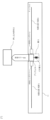
図1は実施形態1の構成図である。この光スイッチ10は光ファイバFA及び光ファイバFBの上部側ファイバ群と、光ファイバFC及び光ファイバFDの下部側ファイバ群を光路切替して接続するものである。
(Embodiment 1)
1 is a configuration diagram of
光サーキュレータ30Aは、本実施形態で後述する3ポート光サーキュレータである。光ファイバFAと光ファイバFCは光サーキュレータ30Aで接続されており、光ファイバFBと光ファイバFDは光サーキュレータ30Bで接続されている。光サーキュレータ30Aは光ファイバFEを経由してPLC(Planar Lightwave Circuit)11へ接続され、光サーキュレータBは光ファイバFFを経由してPLC11へ接続される。The
PLC11には板状のクラッドに導波路12があり、その導波路12上には両面ミラーを差し込むための溝13が導波路12を横断するように配置されている。溝13は、クラッドの厚さ方向に形成されている。本実施形態では、溝13で分断された導波路12を符号12-1及び12-2と表記し、これらを区別しない場合は導波路12と記載する。また以下の実施形態では、導波路12が直線状に形成されている例を示すが、導波路12はPLCの設計に応じた任意の形状でありうる。また光導波路12-1及び12-2の長さは、同じであってもよいが、異なっていても本開示の作用・効果は得られる。
本実施形態では、溝13へ差し込むことができる両面ミラーMAが配置されている。両面ミラーMAは、クラッドの厚さ方向に移動可能である。両面ミラーMAは、溝13内で光導波路12-1及び12-2に挟まれた際に、光導波路12-1及び12-2から入射された光を入射方向と逆方向に反射する。In this embodiment, a double-sided mirror MA is provided that can be inserted into
本実施形態では、溝13へ差し込むことができるプリズム(図5に示す符号16)が配置されている。プリズム16は、クラッドの厚さ方向に移動可能である。プリズム16は、溝13内で光導波路12-1及び12-2に挟まれた際に、光導波路12-1及び12-2から入射された光を透過する。ここで、プリズム16は、光導波路12-1及び12-2の伝搬光を透過する透明な任意の媒体であり、空気であってもよい。In this embodiment, a prism (
本実施形態では、溝13に露出する対向レンズ(図5に示す符号14-4及び14-5)を備える。対向レンズ14-4が備わる場合、光導波路12-1から溝13への光は対向レンズ14-4を介して溝13に出射される。対向レンズ14-5が備わる場合、光導波路12-2から溝13への光は対向レンズ14-5を介して溝13に出射される。In this embodiment, there are opposing lenses (reference numerals 14-4 and 14-5 shown in FIG. 5) exposed to groove 13. When opposing lens 14-4 is provided, light from optical waveguide 12-1 to groove 13 is emitted to groove 13 via opposing lens 14-4. When opposing lens 14-5 is provided, light from optical waveguide 12-2 to groove 13 is emitted to groove 13 via opposing lens 14-5.
PLC11の内部には、一端がPLC11の表面で光ファイバFEに接続された光導波路12-1、及び一端がPLC11の光ファイバFFに接続された光導波路12-2が同軸上に配置されている。光導波路12-1の他端及び光導波路12-2の他端の間には、両面ミラーMAを差し込むための溝13が設けられている。光導波路12-1の他端及び光導波路12-2の他端を光学的に接続するために、溝13の内部かつ光導波路12-1及び光導波路12-2の軸上に、光を透過するプリズム(後述する符号16)のような透明体が配置されてもよい。両面ミラーMAは、溝13に挿入可能な位置、例えば、溝13の上や、溝13内に両面ミラーMAを配置され、溝13に挿入されたり、溝13から抜き出されたりすることで、光導波路12-1及び光導波路12-2の間の光学的接続状態(遮断又は接続)を変化させる。Inside
ここで、図1では、光ファイバFAを光路1Aとし、光ファイバFCを光路1Cとし、光路1A及び光路1Cをまとめて光路1とする。また、光ファイバFBを光路2Bとし、光ファイバFDを光路2Dとし、光路2B及び光路2Dをまとめて光路2とする。さらに、光ファイバFE、光導波路12-1、光導波路12-2及び光ファイバFFをまとめて光路3とする。
Here, in Figure 1, the optical fiber FA is designated as optical path 1A, the optical fiber FC is designated as optical path 1C, and optical path 1A and optical path 1C are collectively designated as
溝13と両面ミラーMAの位置関係の一例を説明するため、光ファイバFA及び光ファイバFBの長軸方向からみたPLC11の側面図を図2に示す。光路3は、PLC11の内部を直線状に貫通しており、溝13が光路3に垂直に設けられている。そして、この溝13に対して両面ミラーMAを挿入することで、光路3を遮断する。また、溝13に挿入された両面ミラーMAは、光路3に対して垂直な方向に抜き出されることで、光路3の光学的な接続を可能とする。両面ミラーMAの駆動方法は後述する。
To explain an example of the positional relationship between the
バルク部品で構成される光サーキュレータ30Aと光導波路12との間の構成の一例を図3で説明する。光導波路12に接続された光ファイバFEと、光サーキュレータ30Aの有するレンズ14-2とが光学的に接続されることで、光サーキュレータ30Aと光導波路12との間での光の入出力が実現される。一方、既存技術である導波路型光サーキュレータも用いることもできる(例えば、特許文献1~3を参照。)。An example of the configuration between the
図1における光サーキュレータ30Aの動作原理を図4で説明する。図4では、光サーキュレータ30Aの一例として、バルク部品で構成される光サーキュレータを表す。光路1Aから送信された光は、偏光ビームスプリッタSAでS偏光とP偏光に分けられる。P偏光はそのまま、S偏光は片面ミラーCMAで反射された後に、それぞれ1/2波長板、ファラデー回転子の順でこれらを通り、偏光ビームスプリッタSBで合波されて光路3へ進む。なお、P偏光及びS変更は、1/2波長板、ファラデー回転子の順に、これらを通過する場合は偏光状態が変化しない。
The operating principle of the
また、光路3から来た光は偏光ビームスプリッタSBでS偏光とP偏光に分けられる。偏光ビームスプリッタSBで分けられたS偏光及びP偏光はそれぞれ、ファラデー回転子、1/2波長板の順にこれらを通過することで、偏光状態が90度回転し、偏光ビームスプリッタSAで合波した後に、片面ミラーCMB、片面ミラーCMC及び両面ミラーCMBで反射されて光路1Cへ進む。図1の光サーキュレータ30Bは光サーキュレータ30Aと左右対称の構造となる。
In addition, the light coming from
両面ミラーMAを溝13に挿入する方法について図5から図8を用いて説明する。両面ミラーMAを溝13に挿入する前の状態の一例を図5(a)に示す。図5(a)に示すように、PLC11には、前述したように溝13が光路3に垂直に設けられている。PLC11は、溝13に露出し、互いに対向する対向レンズ17-1及び対向レンズ17-2を有する。また、光導波路12-1は、一端が光路1を構成する光ファイバFE(不図示)に接続され、他端が対向レンズ17-1に接続する。光導波路12-2は、一端が光路2を構成する光ファイバFF(不図示)に接続され、他端が対向レンズ17-2に接続する。
The method of inserting the double-sided mirror MA into the
両面ミラーMAの構造例を図5(b)に示す。図5(b)に示すように、両面ミラーMAはプリズム16と接着されており、またプリズム16の下には、プリズム16の押し込みに対して反発力を持つバネ等15を取り付ける。バネ等15は、図5(a)に示すように溝13の底と接続される。両面ミラーMAとプリズム16との位置関係はこれに限定されない。例えば、両面ミラーMAとプリズム16とが図5(a)に示す位置関係と上下が反対で、両面ミラーMAと溝13の底とがバネ等15で接続されてもよい。光スイッチ10は、窪みの有る板21を備えてもよい。窪みの有る板21は、押し込み部材として機能し、両面ミラーMAの上部が窪み21Dに入るように配置され、この状態からPLC11の厚さ方向と垂直な光路方向に移動可能である。窪み21Dは、板21の押し込み面21Sに配置され、PLC11のクラッドに対して斜めになっている。押し込み面21Sが光路方向に動くことで、両面ミラーの溝13への押し込み量を制御することができる。また、両面ミラーMAが窪みに入っている場合に、プリズム16が光導波路12-1及び光導波路12-2の軸上に配置されるように、バネ等15の長さ及び強度並びに板21とPLC11との距離が調整されることが望ましい。両面ミラーMAが窪みに入っている場合は、光路3を通る光が光導波路12-1、対向レンズ17-1、プリズム16、光導波路12-2及び対向レンズ17-2を通過する。ここで、対向レンズ17-1、プリズム16及び対向レンズ17-2はそれぞれ光路3に含まれるとする。
An example of the structure of the double-sided mirror MA is shown in FIG. 5(b). As shown in FIG. 5(b), the double-sided mirror MA is bonded to the
窪みの有る板21をPLC11の光路3に対して平行移動させた図が図6である。窪みの有る板21の平行移動により両面ミラーMAは窪みから外れ、PLC11へ押し込まれる形で両面ミラーMAが溝13へ挿入される。これにより、光路3上にあったプリズム16が両面ミラーMAに変わり、光路1から来た光は光路1方向へ、光路2方向から来た光は光路2方向へ全反射する。窪みの有る板21代わりに、斜面を有する板を用いて同様である。図7及び図8は窪みの有る板21の代わりに、押し込み部材22により両面ミラーMAの押し込みを実行する構成である。押し込み部材22は、温度変化などにより意図的に膨張収縮を制御できる部材や、モータ等の回転をピストン運動等へ変換する機構を用いても良い。プリズム16により遮断された光路3については、光路3のうち、両面ミラーMAより光路1側の部分を光路3Eとし、両面ミラーMAより光路2側の部分を光路3Fとする。
Figure 6 shows the
図1の光スイッチ10において、両面ミラーMAを用いた光路切替の一例を図9及び図10で説明する。図9は、両面ミラーMA(不図示)が溝13へ挿入されていない状態の光スイッチ10を表す。本実施形態に係る光スイッチ10では、図9のように、光ファイバFAから光サーキュレータ30Aに向けて入射された光は、光サーキュレータ30Aを通って光路3へ出射された後、光サーキュレータ30Bを通って光ファイバFDへ出射される。同様に、光ファイバFBから光サーキュレータ30Bに向けて入射された光は、光サーキュレータ30Bを通って光路3へ出射された後、光サーキュレータ30Aを通って光ファイバFCへ出射される。
An example of optical path switching using a double-sided mirror MA in the
次に、両面ミラーMAを溝13に挿入した場合について図10で説明する。図10に示すように、両面ミラーMAを溝13へ挿入すると、光ファイバFAから光サーキュレータ30Aへ向けて入射された光は、光サーキュレータ30Aを通って光路3Eへ出射されるが、その後両面ミラーMAによって反射され、再び光路3Eを光サーキュレータ30Aに向かって伝搬し、光サーキュレータ30Aを通って光ファイバFCへ出射される。同様に、光ファイバFBから光サーキュレータ30Bに向かって入射された光も両面ミラーMAで反射されることで、最終的に光ファイバFDへ出射される。よって、本実施形態に係る光スイッチ10は、図9及び図10に示すように、両面ミラーMAを溝13に挿入するか否かによって、光路を変えることができ、光スイッチとして機能する。Next, the case where the double-sided mirror MA is inserted into the
上記では、2入力2出力として機能する光スイッチ10を説明したが、光スイッチ10を組み合わせることで、3入力3出力以上の光スイッチを実現できる。3入力3出力として機能する光スイッチの一例を図11に示す。図11では、A軸、B軸及びC軸の3軸上に光ファイバ及び光サーキュレータを配置する。具体的には、A軸上に、3本の光ファイバと、それぞれの間に光サーキュレータ30A又は30Eを配置する。B軸上に、4本の光ファイバと、それぞれの間に光サーキュレータ30B、30C又は30Fを配置する。C軸上に、2本の光ファイバと、その間に光サーキュレータ30Dを配置する。そして、A軸及びB軸の間には、PLC11Aを配置する。PLC11Aは、前述した光路3を平行に2つ有し、それぞれの光路3に対して前述した両面ミラーMAと同じ構造及び動作の両面ミラーMA及び両面ミラーMCが配置された構成である。PLC11Aは、光サーキュレータ30A及び30Bの間と、光サーキュレータ30E及び30Fの間のそれぞれを2つの光路3で結ぶ。B軸及びC軸の間には、前述したPLC11と同一であるPLC11Bを配置し、光サーキュレータ30C及び30Dの間を光路3で結ぶ。図11に示す光スイッチは、両面ミラーMA、B及びCの挿入・未挿入状態は独立して制御することにより任意の光路切替を実現し、3入力3出力光スイッチとして機能する。
In the above, the
3入力3出力光スイッチの光路切替のパターンの組合せと駆動ミラーの番号を図12に表す。駆動ミラーとは、溝に挿入された状態の両面ミラーを意味する。図12に示す組合せは、左からA軸に入力された光の出力先、B軸に入力された光の出力先、C軸に入力された光の出力先を表す。例えば、図12の1行目は、図12で番号1として表現される両面ミラーM1、図12で番号2として表現される両面ミラーM2、及び図12で番号3として表現される両面ミラーM3のいずれも駆動させなかった場合であり、その場合、A軸に入力した光がA軸に出力され、B軸に入力された光がB軸に出力され、C軸に入力された光がC軸に出力されることを意味する。3入力3出力光スイッチにおける光路切替のパターンの組合せは、入力及び出力が3つなので、光路切替のパターンの組合せは3の階乗で計算でき、6通りとなる。
The combinations of the optical path switching patterns of a 3-input 3-output optical switch and the numbers of the driving mirrors are shown in FIG. 12. The driving mirror means a double-sided mirror inserted in a groove. The combinations shown in FIG. 12 represent the output destination of the light input to the A axis, the output destination of the light input to the B axis, and the output destination of the light input to the C axis from the left. For example, the first line of FIG. 12 shows the case where none of the double-sided mirror M1 represented as
4入力4出力光スイッチの一例を図13に示す。図11に示す3入力3出力光スイッチと同様に、複数の光ファイバ、光サーキュレータ及びPLCを組み合わせることで、4入力4出力光スイッチを実現することができる。また、4入力4出力光スイッチの光路切替のパターンの組合せと駆動ミラーの番号を図14に表す。4入力4出力光スイッチは入力及び出力が4つなので、光路切替のパターンの組合せは4の階乗で計算でき、24通りとなる。 An example of a 4-input 4-output optical switch is shown in Figure 13. As with the 3-input 3-output optical switch shown in Figure 11, a 4-input 4-output optical switch can be realized by combining multiple optical fibers, optical circulators, and PLCs. Figure 14 shows the combinations of optical path switching patterns and the drive mirror numbers of a 4-input 4-output optical switch. As a 4-input 4-output optical switch has four inputs and four outputs, the combinations of optical path switching patterns can be calculated as a factorial of 4, resulting in 24 different combinations.
以上のようにして、上部側ファイバ群から入射された光を任意の下部側ファイバ群へ出射される光路切替を実行する光スイッチを構成する。In this way, an optical switch is constructed that performs optical path switching so that light input from the upper fiber group is output to any of the lower fiber groups.
(実施形態2)
実施形態1に係る光スイッチ10は、上部側ファイバ群である光ファイバFA及び光ファイバFBのいずれかから入射された光を、下部側ファイバ群である光ファイバFC及び光ファイバFDのいずれかへ出射するものであり、上部側ファイバ群から下部側ファイバ群に向けた片方向への光信号にしか適用できない光スイッチであった。
(Embodiment 2)
The
本実施形態に係る光スイッチ40を図15に示す。本実施形態に係る光スイッチ40は、光ファイバFE及び光ファイバFFの上部側ファイバ群からの光でも、光ファイバFG及び光ファイバFHの下部側ファイバ群からの光でも光路切替をできる、双方向の光スイッチである。The
本実施形態では、図15に示すように、光ファイバFEと光ファイバFGは光サーキュレータ31Aで接続されており、光ファイバFFと光ファイバFHは光サーキュレータ31Bで接続されている。また、光ファイバFEを光路4Eとし、光ファイバFGを光路4Gとして、光路4E及び光路4Gをまとめて光路4とする。同様に、光ファイバFFを光路5Fとし、光ファイバFHを光路5Hとして、光路5F及び光路5Hをまとめて光路5とする。15, in this embodiment, the optical fiber FE and the optical fiber FG are connected by the
光サーキュレータ31A及び光サーキュレータ31Bの間は、光路6及び光路7の2つの光路が配置される。光路6及び光路7のそれぞれは、実施形態1における光路3と同様の構成であり、互いに平行である。ただし、光路6及び光路7の両方の光路上にある溝13は共通であり、共通の両面ミラーMAが溝13に挿入されることにより光路6及び光路7を同時に遮断できる。また、光路6及び光路7を構成するプリズムも共通である。なお、両面ミラーMAの構造及び動作は実施形態1と同様である。Two optical paths,
双方向光サーキュレータ31Aの構成及び動作の一例を図16及び図17に示す。双方向光サーキュレータ31Aは、図4に示す光サーキュレータ30Aと比較して、光路7との界面となるレンズ14-4と、レンズ14-4へ光を反射し、又はレンズ14-4からの光を反射する片面ミラーCMGをさらに備えることが特徴である。An example of the configuration and operation of the bidirectional
図16では、光路4E、光路4G及び光路6がそれぞれ、実施形態1における光路1A、光路1C及び光路3に対応する。そして、図16に示す双方向光サーキュレータ31Aは、図4に示す光サーキュレータ30Aと同様の動作を行う。すなわち、図16は、上部側ファイバ群から下部側ファイバ群へ向けて進行する光の光路切替時における光ファイバ40の動作を表している。上部側ファイバ群である光ファイバFEから入射された光は光路4Eから双方向光サーキュレータ31Aへ入り、図4の光サーキュレータ30Aと同様に進行して光路6へ進む。また光路6から入射した光も図4の光サーキュレータ30Aと同じように進行して下部ファイバ群側の光路4Gへ進行する。
In FIG. 16, optical path 4E, optical path 4G, and
一方で、図17は下部側ファイバ群から上部側ファイバ群へ向けて進行する光の光路切替時における双方向光サーキュレータ31Aの動作を表しており、これは実施形態1の光サーキュレータ30Aにない動作である。図17は下部側ファイバ群である光ファイバFGから入射された光は光路4Gから双方向光サーキュレータ31Aへ入り、片面ミラーCMF、片面ミラーCME及び両面ミラーCMCの順にそれぞれで反射された後に、偏光ビームスプリッタSCでP偏光とS偏光へ分波される。その後、S偏光はそのまま、P偏光は片面ミラーCMDで反射された後に、それぞれ1/2波長板、ファラデー回転子でこれらを通過し、偏光ビームスプリッタSDで合波された後に、片面ミラーCMGで反射されて光路7へ進む。なお、P偏光及びS変更は、1/2波長板、ファラデー回転子の順に、これらを通過する場合は偏光状態が変化しない。
On the other hand, Figure 17 shows the operation of the bidirectional
また、光路7から双方向光サーキュレータ31Aへ入射した光は、片面ミラーCMGで反射された後、偏光ビームスプリッタSDでP偏光とS偏光へ分波される。そして、P偏光はそのまま、S偏光は片面ミラーCMCで反射された後に、それぞれファラデー回転子、1/2波長板の順にこれらを通過することで、偏光状態が90度回転し、偏光ビームスプリッタSCで合波されて上部側ファイバ群に向けて光路4Eへ出射される。
The light entering the bidirectional
以上のように、双方向光サーキュレータ31Aは、上部側ファイバ群の光路4Eから光が入射したら光路6へ出射し、光路6から光が入射したら下部側ファイバ群の光路4Gへ出射し、また下部側ファイバ群の光路4Gから光が入射したら光路7へ出射し、光路7から入射したら上部側ファイバ群の光路4Eへ出射する特徴を持つ。図15における双方向光サーキュレータ31Bは双方向光サーキュレータ31Aと左右逆の構造をとる。As described above, the bidirectional
図15の光スイッチ40において、両面ミラーMAを用いた光路切替の一例を図18から図21で説明する。図18は、両面ミラーMA(不図示)が溝13へ挿入されていない状態で上部側ファイバ群から光が入射された場合の光の伝搬経路を表す。光ファイバFEから光サーキュレータ31Aに向けて入射された光は、光サーキュレータ31Aを通って光路6へ出射された後、光サーキュレータ31Bを通って光ファイバFHへ出射される。同様に、光ファイバFFから光サーキュレータ31Bに向けて入射された光は、光サーキュレータ31Bを通って光路6へ出射された後、光サーキュレータ31Aを通って光ファイバFGへ出射される。
An example of optical path switching using a double-sided mirror MA in the
図19は、両面ミラーMA(不図示)が溝13へ挿入されていない状態で下部側ファイバ群から光が入射された場合の光の伝搬経路を表す。光ファイバFGから光サーキュレータ31Aに向けて入射された光は、光サーキュレータ31Aを通って光路7へ出射された後、光サーキュレータ31Bを通って光ファイバFFへ出射される。同様に、光ファイバFHから光サーキュレータ31Bに向けて入射された光は、光サーキュレータ31Bを通って光路7へ出射された後、光サーキュレータ31Aを通って光ファイバFEへ出射される。以上より、双方向光スイッチ40では、光の進行方向が上部側ファイバ群から下部側ファイバ群であっても、下部側ファイバ群から上部側ファイバ群であっても同じ光接続状態、すなわち、入射された光がPLC11を通って、入射軸と異なる軸から出力される状態が形成される。19 shows the propagation path of light when light is incident from the lower fiber group when the double-sided mirror MA (not shown) is not inserted into the
図20は、双方向光スイッチ40に両面ミラーMAが挿入された状態で上部側ファイバ群から光が入射された場合の光の伝搬経路を表す。図20及び後述する図21では、両面ミラーMAにより遮断された光路6については、光路6のうち、両面ミラーMA及び光サーキュレータ31Aの間の部分を光路6Eとし、両面ミラーMA及び光サーキュレータ31Bの間の部分を光路6Fとする。光路7についても同様に両面ミラーMAで光路7Eと光路7Fに分割されるとする。
Figure 20 shows the light propagation path when light is input from the upper fiber group with the double-sided mirror MA inserted in the bidirectional
図20に示すように、両面ミラーMAを溝13へ挿入すると、光ファイバFEから光サーキュレータ31Aへ向けて入射された光は、光サーキュレータ31Aを通って光路6Eへ出射されるが、その後両面ミラーMAによって反射され、再び光路6Eを光サーキュレータ31Aに向かって伝搬し、光サーキュレータ31Aを通って光ファイバFGへ出射される。同様に、光ファイバFFから光サーキュレータ31Bに向かって入射された光も両面ミラーMAで反射されることで、最終的に光ファイバFHへ出射される。20, when the double-sided mirror MA is inserted into the
図21は、双方向光スイッチ40に両面ミラーMAが挿入された状態で下部側ファイバ群から光が入射された場合の光の伝搬経路を表す。図21に示すように、両面ミラーMAを溝13へ挿入すると、光ファイバFGから光サーキュレータ31Aへ向けて入射された光は、光サーキュレータ31Aを通って光路7Eへ出射されるが、その後両面ミラーMAによって反射され、再び光路7Eを光サーキュレータ31Aに向かって伝搬し、光サーキュレータ31Aを通って光ファイバFEへ出射される。同様に、光ファイバFHから光サーキュレータ31Bに向かって入射された光も両面ミラーMAで反射されることで、最終的に光ファイバFFへ出射される。以上より、双方向光スイッチ40では、光の進行方向が上部側ファイバ群から下部側ファイバ群であっても、下部側ファイバ群から上部側ファイバ群であっても同じ光接続状態、すなわち、入射された光がPLC11で反射されて、入射軸と同じ軸から出力される状態が形成される。21 shows the propagation path of light when light is input from the lower fiber group with the double-sided mirror MA inserted in the bidirectional
このように、本実施形態に係る光スイッチ40は、実施形態1とは異なり、双方向に光通信する場合においても使用可能な光路切替機能を持つ光スイッチとなる。また双方向光スイッチも実施形態1における図11、図13と同様に3入力3出力以上のN入力N出力スイッチも構成可能である。
Thus, the
(実施形態3)
実施形態1や実施形態2では、光路上にある複数の両面ミラーMAの挿入状態の組み合わせによって上部側ファイバ群と下部側ファイバ群の光路切替を伴う接続を実現する。4入力4出力光スイッチを図22に示す。図22では、光サーキュレータ30としているが、双方向サーキュレータ31でもよい。図22に示すような光スイッチシステム内に複数の両面ミラーがあった場合、複数の両面ミラーMAを一斉に制御してもよい。具体的には、光スイッチシステムは、各両面ミラーMAの位置に対応した窪みを有する窪み制御部材50を有してもよい。図23のように各両面ミラーMAに対応した位置に窪みが彫ってある窪み制御部材を移動させることで、一斉に全ての両面ミラーMAの挿入・非挿入状態を制御しても良い。これにより、各両面ミラーMA1つ1つで両面ミラーMAの駆動を制御する場合に比べて少ないパーツ数で光路切替が実現できる。
(Embodiment 3)
In the first and second embodiments, a connection involving optical path switching between an upper fiber group and a lower fiber group is realized by combining the insertion states of multiple double-sided mirrors MA on the optical path. A four-input four-output optical switch is shown in FIG. 22. In FIG. 22, an optical circulator 30 is used, but a bidirectional circulator 31 may be used. When multiple double-sided mirrors are included in the optical switch system shown in FIG. 22, the multiple double-sided mirrors MA may be controlled simultaneously. Specifically, the optical switch system may have a depression control member 50 having a depression corresponding to the position of each double-sided mirror MA. As shown in FIG. 23, the depression control member having a depression carved into a position corresponding to each double-sided mirror MA may be moved to simultaneously control the insertion/non-insertion state of all double-sided mirrors MA. This allows optical path switching to be realized with a smaller number of parts than when the drive of each double-sided mirror MA is controlled by each double-sided mirror MA.
(実施形態4)
実施形態1の光サーキュレータ30や実施形態2の双方向光サーキュレータ31に関して、図24のように導波路型サーキュレータ32(例えば、特許文献1~3を参照。)によりアレイ化し集積することにより、製造の簡易化やそれに伴う低コスト製造をしても良い。
(Embodiment 4)
Regarding the optical circulator 30 of the first embodiment and the bidirectional optical circulator 31 of the second embodiment, the manufacturing process may be simplified and the manufacturing cost reduced by integrating them into an array using a waveguide-
(発明の効果)
小さく軽量な両面ミラーの駆動のみで光路が切り替わるため従来よりも小さなエネルギーで動作する光スイッチとなる。また、1xNスイッチを複数組み合わせてNxNスイッチを構築する際は1xNスイッチ同士をフルメッシュ状に接続する必要があり、Nの2乗回の融着接続などが発生してスイッチの大型化が課題となるが、本スイッチは小型での製造が可能である。
(Effects of the Invention)
Since the light path is switched simply by driving a small, lightweight double-sided mirror, this optical switch operates with less energy than conventional switches. In addition, when combining multiple 1xN switches to build an NxN switch, the 1xN switches need to be connected in a full mesh pattern, which requires N-squared fusion splices and other operations, making it difficult to increase the size of the switch; however, this switch can be manufactured in a compact size.
(発明のポイント)
PLCと光サーキュレータで構成された光路に両面ミラーを差し込むことによって、光路で形成されたあみだくじのように上部側ファイバ群と下部側ファイバ群のあらゆる接続状態を表現することができる。
(Key points of the invention)
By inserting a double-sided mirror into the optical path consisting of the PLC and the optical circulator, it is possible to realize any connection state between the upper fiber group and the lower fiber group, like a maze of lots formed by the optical path.
本開示に係る光スイッチ及び光スイッチシステムは、情報通信産業に適用することができる。The optical switches and optical switch systems disclosed herein can be applied to the information and communications industry.
10、40:光スイッチ
11:PLC
12、12-1、12-2:光導波路
13:溝
14:レンズ
15:バネ等
16:プリズム
17-1、17-2:対向レンズ
21:窪みの有る板
21D:窪み
21S:押し込み面
22:押し込み部材
30:光サーキュレータ
31:双方向光サーキュレータ
32:導波路型サーキュレータ
10, 40: Optical switch 11: PLC
12, 12-1, 12-2: Optical waveguide 13: Groove 14: Lens 15: Spring, etc. 16: Prism 17-1, 17-2: Opposing lens 21: Plate with
Claims (7)
前記溝に露出する対向レンズと、
前記クラッドの内部で同軸上にそれぞれ配置され、それぞれの一端が前記クラッドの表面に露出し、それぞれの他端が前記対向レンズを介して前記溝で向かい合う2本の光導波路と、
前記溝内で前記対向レンズに挟まれた際に前記対向レンズの光を透過する移動可能な透明体と、
前記溝内で前記対向レンズに挟まれた際に前記対向レンズから入射された光を入射方向と逆方向に反射する移動可能な両面ミラーと、
前記透明体及び前記両面ミラーが前記厚さ方向に重なって構成される可動部と、
前記可動部と前記溝の底とを接続するバネと、
前記両面ミラーの上部に接触する押し込み面を有し、前記押し込み面が動くことにより、前記両面ミラーの前記溝への押し込み量を制御する押し込み部材と、
を備える光スイッチ。 A plate-shaped clad having a groove in the thickness direction;
an opposing lens exposed in the groove;
two optical waveguides each arranged coaxially inside the clad, one end of each of which is exposed on the surface of the clad and the other end of each of which faces each other in the groove via the opposing lens;
a movable transparent body that transmits light from the opposing lens when sandwiched between the opposing lens in the groove;
a movable double-sided mirror that, when sandwiched between the opposing lenses in the groove, reflects light incident from the opposing lens in a direction opposite to the incident direction;
a movable portion formed by overlapping the transparent body and the double-sided mirror in the thickness direction;
A spring connecting the movable portion and the bottom of the groove;
a pressing member having a pressing surface that contacts an upper portion of the double-sided mirror and that controls an amount of pressing of the double-sided mirror into the groove by moving the pressing surface;
An optical switch comprising:
ことを特徴とする請求項1に記載の光スイッチ。 The optical switch according to claim 1, characterized in that the pushing member has a pushing surface that is inclined with respect to the cladding, and the pushing surface moves in a direction perpendicular to the thickness direction to control the amount of pushing of the double -sided mirror into the groove.
前記クラッドの内部で、前記2本の光導波路の軸に平行な軸上にそれぞれ配置され、それぞれの一端が前記クラッドの表面に露出し、それぞれの他端が前記第2対向レンズを介して前記溝で向かい合う2本の第2光導波路と、をさらに備え、
前記透明体は、前記第2対向レンズに挟まれた際に前記第2対向レンズの光を透過し、
前記両面ミラーは、前記第2対向レンズに挟まれた際に前記第2対向レンズから入射された光を入射方向と逆方向に反射する
ことを特徴とする請求項1又は2に記載の光スイッチ。 a second opposing lens exposed in the groove;
two second optical waveguides, each disposed inside the clad on an axis parallel to the axes of the two optical waveguides, each having one end exposed on a surface of the clad and the other end facing each other in the groove via the second opposing lens;
the transparent body transmits light from the second opposing lens when sandwiched between the second opposing lenses,
3. The optical switch according to claim 1 , wherein the double-sided mirror reflects light incident from the second opposing lens in a direction opposite to the incident direction when the double-sided mirror is sandwiched between the second opposing lenses.
第1ポートからの光の入力を第2のポートへ出力し、第2ポートからの光の入力を第3ポートに出力する2つの3ポートの光サーキュレータと、
前記2つの3ポートの光サーキュレータの第1ポートに接続される2本の上部側光ファイバと、
前記2つの3ポートの光サーキュレータの第2のポートと前記2本の光導波路の前記一端とを接続する2本の接続光ファイバと、
前記2つの3ポートの光サーキュレータの第3ポートに接続される2本の下部側光ファイバと、を備える光スイッチシステムであって、
任意の前記上部側光ファイバから入射された光を任意の前記下部側光ファイバに出射し、2入力2出力光スイッチとして機能する
ことを特徴とする光スイッチシステム。 An optical switch according to claim 1 or 2 ;
two three- port optical circulators each configured to receive an optical input from a first port and output the optical input from the second port to a third port;
two upper optical fibers connected to first ports of the two three-port optical circulators;
two connecting optical fibers connecting second ports of the two three-port optical circulators to the one ends of the two optical waveguides;
and two lower optical fibers connected to the third ports of the two three-port optical circulators,
An optical switch system which functions as a two-input, two-output optical switch by outputting light incident on any one of said upper optical fibers to any one of said lower optical fibers.
第1ポートからの光の入力を第2のポートへ出力し、第2ポートからの光の入力を第3ポートに出力し、第3ポートからの光の入力を第4ポートに出力し、第4ポートからの光の入力を第1ポートに出力する2つの4ポートの光サーキュレータと、
前記2つの4ポートの光サーキュレータの第1ポートに接続される2本の上部側光ファイバと、
前記2つの4ポートの光サーキュレータの第2のポートと前記2本の光導波路の前記一端とを接続する2本の第1接続光ファイバと、
前記2つの4ポートの光サーキュレータの第3ポートに接続される2本の下部側光ファイバと、
前記2つの4ポートの光サーキュレータの第4のポートと前記2本の第2光導波路の前記一端とを接続する2本の第2接続光ファイバと、を備える光スイッチシステムであって、
任意の前記上部側光ファイバから入射された光を任意の前記下部側光ファイバに出射し、任意の前記下部側光ファイバから入射された光を任意の前記上部側光ファイバに出射し、2入力2出力光スイッチとして機能する
ことを特徴とする光スイッチシステム。 An optical switch according to claim 3 ;
two four-port optical circulators each receiving an optical input from a first port and outputting the optical input from the second port to a third port, receiving an optical input from the third port to a fourth port, and outputting an optical input from the fourth port to the first port;
two upper optical fibers connected to first ports of the two four-port optical circulators;
two first connecting optical fibers connecting second ports of the two four- port optical circulators to the one ends of the two optical waveguides;
two lower optical fibers connected to the third ports of the two four-port optical circulators;
an optical switch system including: two second connection optical fibers connecting fourth ports of the two four-port optical circulators to the one ends of the two second optical waveguides;
An optical switch system characterized by functioning as a two-input, two-output optical switch, by emitting light incident from any of the upper-side optical fibers to any of the lower-side optical fibers, and emitting light incident from any of the lower-side optical fibers to any of the upper-side optical fibers.
ことを特徴とする光スイッチシステム。 6. An optical switch system comprising a combination of the optical switch systems according to claim 4 or 5 , which functions as an N-input N-output optical switch.
ことを特徴とする請求項4から6のいずれかに記載の光スイッチシステム。 7. The optical switch system according to claim 4 , wherein the optical circulator is a waveguide type circulator.
Applications Claiming Priority (1)
| Application Number | Priority Date | Filing Date | Title |
|---|---|---|---|
| PCT/JP2021/032108 WO2023032071A1 (en) | 2021-09-01 | 2021-09-01 | Optical switch and optical switch system |
Publications (2)
| Publication Number | Publication Date |
|---|---|
| JPWO2023032071A1 JPWO2023032071A1 (en) | 2023-03-09 |
| JP7601238B2 true JP7601238B2 (en) | 2024-12-17 |
Family
ID=85410977
Family Applications (1)
| Application Number | Title | Priority Date | Filing Date |
|---|---|---|---|
| JP2023544865A Active JP7601238B2 (en) | 2021-09-01 | 2021-09-01 | Optical switch and optical switch system |
Country Status (3)
| Country | Link |
|---|---|
| US (1) | US20250130371A1 (en) |
| JP (1) | JP7601238B2 (en) |
| WO (1) | WO2023032071A1 (en) |
Citations (5)
| Publication number | Priority date | Publication date | Assignee | Title |
|---|---|---|---|---|
| JP2000010027A (en) | 1998-06-18 | 2000-01-14 | Alps Electric Co Ltd | Optical switch and optical communication device using the same |
| JP2002023069A (en) | 2000-07-12 | 2002-01-23 | Sumitomo Electric Ind Ltd | Light switch |
| JP2004205631A (en) | 2002-12-24 | 2004-07-22 | Seiko Instruments Inc | Optical device |
| JP2005333458A (en) | 2004-05-20 | 2005-12-02 | Nippon Telegr & Teleph Corp <Ntt> | Optical cross-connect device |
| JP2010284738A (en) | 2009-06-10 | 2010-12-24 | Japan Aviation Electronics Industry Ltd | Micro movable device |
Family Cites Families (4)
| Publication number | Priority date | Publication date | Assignee | Title |
|---|---|---|---|---|
| US4315147A (en) * | 1980-02-15 | 1982-02-09 | Battelle Memorial Institute | Photoelectric switch with visible signal |
| JPS56128608U (en) * | 1980-03-03 | 1981-09-30 | ||
| JPS5788404A (en) * | 1980-11-20 | 1982-06-02 | Toshiba Corp | Optical switch |
| US6424759B1 (en) * | 1999-10-12 | 2002-07-23 | Primawave Photonics, Inc. | Mechanically actuated MXN optical switch matrix |
-
2021
- 2021-09-01 US US18/686,811 patent/US20250130371A1/en active Pending
- 2021-09-01 JP JP2023544865A patent/JP7601238B2/en active Active
- 2021-09-01 WO PCT/JP2021/032108 patent/WO2023032071A1/en not_active Ceased
Patent Citations (5)
| Publication number | Priority date | Publication date | Assignee | Title |
|---|---|---|---|---|
| JP2000010027A (en) | 1998-06-18 | 2000-01-14 | Alps Electric Co Ltd | Optical switch and optical communication device using the same |
| JP2002023069A (en) | 2000-07-12 | 2002-01-23 | Sumitomo Electric Ind Ltd | Light switch |
| JP2004205631A (en) | 2002-12-24 | 2004-07-22 | Seiko Instruments Inc | Optical device |
| JP2005333458A (en) | 2004-05-20 | 2005-12-02 | Nippon Telegr & Teleph Corp <Ntt> | Optical cross-connect device |
| JP2010284738A (en) | 2009-06-10 | 2010-12-24 | Japan Aviation Electronics Industry Ltd | Micro movable device |
Also Published As
| Publication number | Publication date |
|---|---|
| US20250130371A1 (en) | 2025-04-24 |
| JPWO2023032071A1 (en) | 2023-03-09 |
| WO2023032071A1 (en) | 2023-03-09 |
Similar Documents
| Publication | Publication Date | Title |
|---|---|---|
| JPH04287010A (en) | Waveguide type optical switch | |
| KR20220068259A (en) | Optical switch controllable by vertical motion MEMS structure | |
| EP2691801B1 (en) | Optical device having an elastomeric waveguide switch body and related methods | |
| US20040096145A1 (en) | Optical switching and attenuation systems and methods therefor | |
| JP7601238B2 (en) | Optical switch and optical switch system | |
| US6961486B2 (en) | Non-blocking mechanical fiber optic matrix switch | |
| CN110456531A (en) | A kind of miniature magneto-optic fiber switch | |
| US6920258B2 (en) | Optical switch | |
| CN107850736B (en) | an optical cross-connector | |
| KR100464753B1 (en) | Optical Switch | |
| JP3932915B2 (en) | Light switch | |
| JP3090610U (en) | Optical path switching device | |
| CN1420375A (en) | Multi-light path photoswitch | |
| US7162118B1 (en) | Dual optical switch | |
| JP4412665B2 (en) | Variable optical multiplexer / demultiplexer | |
| JP2006243013A (en) | Multiport optical switch | |
| KR20250157432A (en) | Polarization-diversity integrated photonic switch with multilayer waveguides | |
| CN211826609U (en) | Optical switch based on MEMS | |
| US20040013354A1 (en) | Systems and methods for selectively routing optical signals | |
| KR100412341B1 (en) | Optical Switch | |
| CN101149451A (en) | Optical switch | |
| CN112444915B (en) | Optical switch and optical transmission method through optical switch | |
| US20030174933A1 (en) | Optical switch | |
| KR100446909B1 (en) | Optical Switch | |
| CN2557965Y (en) | Multi-light path light switch |
Legal Events
| Date | Code | Title | Description |
|---|---|---|---|
| A621 | Written request for application examination |
Free format text: JAPANESE INTERMEDIATE CODE: A621 Effective date: 20240216 |
|
| A131 | Notification of reasons for refusal |
Free format text: JAPANESE INTERMEDIATE CODE: A131 Effective date: 20240903 |
|
| A521 | Request for written amendment filed |
Free format text: JAPANESE INTERMEDIATE CODE: A523 Effective date: 20241024 |
|
| TRDD | Decision of grant or rejection written | ||
| A01 | Written decision to grant a patent or to grant a registration (utility model) |
Free format text: JAPANESE INTERMEDIATE CODE: A01 Effective date: 20241105 |
|
| A61 | First payment of annual fees (during grant procedure) |
Free format text: JAPANESE INTERMEDIATE CODE: A61 Effective date: 20241118 |
|
| R150 | Certificate of patent or registration of utility model |
Ref document number: 7601238 Country of ref document: JP Free format text: JAPANESE INTERMEDIATE CODE: R150 |
|
| S533 | Written request for registration of change of name |
Free format text: JAPANESE INTERMEDIATE CODE: R313533 |
|
| R350 | Written notification of registration of transfer |
Free format text: JAPANESE INTERMEDIATE CODE: R350 |