JP7601603B2 - Cold Plate - Google Patents
Cold Plate Download PDFInfo
- Publication number
- JP7601603B2 JP7601603B2 JP2020178103A JP2020178103A JP7601603B2 JP 7601603 B2 JP7601603 B2 JP 7601603B2 JP 2020178103 A JP2020178103 A JP 2020178103A JP 2020178103 A JP2020178103 A JP 2020178103A JP 7601603 B2 JP7601603 B2 JP 7601603B2
- Authority
- JP
- Japan
- Prior art keywords
- fins
- resin cover
- metal plate
- roughened
- roughened portion
- Prior art date
- Legal status (The legal status is an assumption and is not a legal conclusion. Google has not performed a legal analysis and makes no representation as to the accuracy of the status listed.)
- Active
Links
Images




Classifications
-
- F—MECHANICAL ENGINEERING; LIGHTING; HEATING; WEAPONS; BLASTING
- F28—HEAT EXCHANGE IN GENERAL
- F28F—DETAILS OF HEAT-EXCHANGE AND HEAT-TRANSFER APPARATUS, OF GENERAL APPLICATION
- F28F3/00—Plate-like or laminated elements; Assemblies of plate-like or laminated elements
- F28F3/12—Elements constructed in the shape of a hollow panel, e.g. with channels
-
- F—MECHANICAL ENGINEERING; LIGHTING; HEATING; WEAPONS; BLASTING
- F28—HEAT EXCHANGE IN GENERAL
- F28D—HEAT-EXCHANGE APPARATUS, NOT PROVIDED FOR IN ANOTHER SUBCLASS, IN WHICH THE HEAT-EXCHANGE MEDIA DO NOT COME INTO DIRECT CONTACT
- F28D1/00—Heat-exchange apparatus having stationary conduit assemblies for one heat-exchange medium only, the media being in contact with different sides of the conduit wall, in which the other heat-exchange medium is a large body of fluid, e.g. domestic or motor car radiators
- F28D1/02—Heat-exchange apparatus having stationary conduit assemblies for one heat-exchange medium only, the media being in contact with different sides of the conduit wall, in which the other heat-exchange medium is a large body of fluid, e.g. domestic or motor car radiators with heat-exchange conduits immersed in the body of fluid
- F28D1/03—Heat-exchange apparatus having stationary conduit assemblies for one heat-exchange medium only, the media being in contact with different sides of the conduit wall, in which the other heat-exchange medium is a large body of fluid, e.g. domestic or motor car radiators with heat-exchange conduits immersed in the body of fluid with plate-like or laminated conduits
- F28D1/0358—Heat-exchange apparatus having stationary conduit assemblies for one heat-exchange medium only, the media being in contact with different sides of the conduit wall, in which the other heat-exchange medium is a large body of fluid, e.g. domestic or motor car radiators with heat-exchange conduits immersed in the body of fluid with plate-like or laminated conduits the conduits being formed by bent plates
-
- F—MECHANICAL ENGINEERING; LIGHTING; HEATING; WEAPONS; BLASTING
- F28—HEAT EXCHANGE IN GENERAL
- F28F—DETAILS OF HEAT-EXCHANGE AND HEAT-TRANSFER APPARATUS, OF GENERAL APPLICATION
- F28F13/00—Arrangements for modifying heat-transfer, e.g. increasing, decreasing
- F28F13/06—Arrangements for modifying heat-transfer, e.g. increasing, decreasing by affecting the pattern of flow of the heat-exchange media
- F28F13/08—Arrangements for modifying heat-transfer, e.g. increasing, decreasing by affecting the pattern of flow of the heat-exchange media by varying the cross-section of the flow channels
-
- F—MECHANICAL ENGINEERING; LIGHTING; HEATING; WEAPONS; BLASTING
- F28—HEAT EXCHANGE IN GENERAL
- F28F—DETAILS OF HEAT-EXCHANGE AND HEAT-TRANSFER APPARATUS, OF GENERAL APPLICATION
- F28F21/00—Constructions of heat-exchange apparatus characterised by the selection of particular materials
- F28F21/08—Constructions of heat-exchange apparatus characterised by the selection of particular materials of metal
- F28F21/081—Heat exchange elements made from metals or metal alloys
-
- F—MECHANICAL ENGINEERING; LIGHTING; HEATING; WEAPONS; BLASTING
- F28—HEAT EXCHANGE IN GENERAL
- F28F—DETAILS OF HEAT-EXCHANGE AND HEAT-TRANSFER APPARATUS, OF GENERAL APPLICATION
- F28F21/00—Constructions of heat-exchange apparatus characterised by the selection of particular materials
- F28F21/08—Constructions of heat-exchange apparatus characterised by the selection of particular materials of metal
- F28F21/089—Coatings, claddings or bonding layers made from metals or metal alloys
-
- F—MECHANICAL ENGINEERING; LIGHTING; HEATING; WEAPONS; BLASTING
- F28—HEAT EXCHANGE IN GENERAL
- F28F—DETAILS OF HEAT-EXCHANGE AND HEAT-TRANSFER APPARATUS, OF GENERAL APPLICATION
- F28F3/00—Plate-like or laminated elements; Assemblies of plate-like or laminated elements
- F28F3/02—Elements or assemblies thereof with means for increasing heat-transfer area, e.g. with fins, with recesses, with corrugations
- F28F3/04—Elements or assemblies thereof with means for increasing heat-transfer area, e.g. with fins, with recesses, with corrugations the means being integral with the element
- F28F3/048—Elements or assemblies thereof with means for increasing heat-transfer area, e.g. with fins, with recesses, with corrugations the means being integral with the element in the form of ribs integral with the element or local variations in thickness of the element, e.g. grooves, microchannels
-
- H—ELECTRICITY
- H05—ELECTRIC TECHNIQUES NOT OTHERWISE PROVIDED FOR
- H05K—PRINTED CIRCUITS; CASINGS OR CONSTRUCTIONAL DETAILS OF ELECTRIC APPARATUS; MANUFACTURE OF ASSEMBLAGES OF ELECTRICAL COMPONENTS
- H05K7/00—Constructional details common to different types of electric apparatus
- H05K7/20—Modifications to facilitate cooling, ventilating, or heating
- H05K7/20218—Modifications to facilitate cooling, ventilating, or heating using a liquid coolant without phase change in electronic enclosures
- H05K7/20254—Cold plates transferring heat from heat source to coolant
-
- H—ELECTRICITY
- H05—ELECTRIC TECHNIQUES NOT OTHERWISE PROVIDED FOR
- H05K—PRINTED CIRCUITS; CASINGS OR CONSTRUCTIONAL DETAILS OF ELECTRIC APPARATUS; MANUFACTURE OF ASSEMBLAGES OF ELECTRICAL COMPONENTS
- H05K7/00—Constructional details common to different types of electric apparatus
- H05K7/20—Modifications to facilitate cooling, ventilating, or heating
- H05K7/2039—Modifications to facilitate cooling, ventilating, or heating characterised by the heat transfer by conduction from the heat generating element to a dissipating body
- H05K7/20509—Multiple-component heat spreaders; Multi-component heat-conducting support plates; Multi-component non-closed heat-conducting structures
-
- F—MECHANICAL ENGINEERING; LIGHTING; HEATING; WEAPONS; BLASTING
- F28—HEAT EXCHANGE IN GENERAL
- F28D—HEAT-EXCHANGE APPARATUS, NOT PROVIDED FOR IN ANOTHER SUBCLASS, IN WHICH THE HEAT-EXCHANGE MEDIA DO NOT COME INTO DIRECT CONTACT
- F28D21/00—Heat-exchange apparatus not covered by any of the groups F28D1/00 - F28D20/00
- F28D2021/0019—Other heat exchangers for particular applications; Heat exchange systems not otherwise provided for
- F28D2021/0028—Other heat exchangers for particular applications; Heat exchange systems not otherwise provided for for cooling heat generating elements, e.g. for cooling electronic components or electric devices
- F28D2021/0029—Heat sinks
-
- F—MECHANICAL ENGINEERING; LIGHTING; HEATING; WEAPONS; BLASTING
- F28—HEAT EXCHANGE IN GENERAL
- F28F—DETAILS OF HEAT-EXCHANGE AND HEAT-TRANSFER APPARATUS, OF GENERAL APPLICATION
- F28F2215/00—Fins
- F28F2215/10—Secondary fins, e.g. projections or recesses on main fins
Landscapes
- Engineering & Computer Science (AREA)
- Physics & Mathematics (AREA)
- Thermal Sciences (AREA)
- Mechanical Engineering (AREA)
- General Engineering & Computer Science (AREA)
- Microelectronics & Electronic Packaging (AREA)
- Cooling Or The Like Of Semiconductors Or Solid State Devices (AREA)
- Cooling Or The Like Of Electrical Apparatus (AREA)
Description
本発明は、コールドプレート及びコールドプレートの製造方法に関するものである。 The present invention relates to a cold plate and a method for manufacturing a cold plate.
下記特許文献1には、複数のフィンが形成された金属プレートと、複数のフィンを覆う金属カバーと、を備え、金属プレートと金属カバーの周縁部が、樹脂による射出成形によって接合されているコールドプレートが開示されている。
The following
近年の電子部品高集積化による発熱密度の増大により、コールドプレートの需要拡大が予測され、より低価格なコールドプレートが求められている。このため、従来の金属カバーを、樹脂カバーに変更することが検討されている。しかしながら、樹脂カバーは、金属カバーよりも剛性が低く、コールドプレートの内部を流れる冷媒の圧力が高い場合、膨らむように変形して亀裂などが発生する可能性があった。 In recent years, the demand for cold plates is expected to increase due to the increase in heat generation density caused by the high integration of electronic components, and there is a demand for lower-cost cold plates. For this reason, there are considerations of changing the conventional metal covers to resin covers. However, resin covers are less rigid than metal covers, and when the pressure of the refrigerant flowing inside the cold plate is high, there is a possibility that the resin covers will swell and deform, causing cracks.
本発明は、上記問題点に鑑みてなされたものであり、冷媒の圧力による樹脂カバーの変形を抑制できるコールドプレート及びコールドプレートの製造方法の提供を目的とする。 The present invention was made in consideration of the above problems, and aims to provide a cold plate and a method for manufacturing the cold plate that can suppress deformation of the resin cover due to refrigerant pressure.
本発明の一態様に係るコールドプレートは、複数のフィンが形成された金属プレートと、前記複数のフィンを覆う樹脂カバーと、を備え、前記複数のフィンの少なくとも一つの先端面には、粗面化部が形成され、前記粗面化部と前記樹脂カバーとが融着されている。
この構成によれば、金属プレートのフィンの先端面に形成した粗面化部によって、フィンと樹脂カバーとを強固に融着できる。このフィンは、樹脂カバーの周縁部よりも内側から樹脂カバーの変形を抑制する。このため、冷媒の圧力による樹脂カバーの膨らむような変形を抑制できる。
A cold plate according to one embodiment of the present invention comprises a metal plate having a plurality of fins formed thereon and a resin cover covering the plurality of fins, wherein a roughened portion is formed on a tip surface of at least one of the plurality of fins and the roughened portion and the resin cover are fused together.
With this configuration, the roughened surface formed on the tip end surface of the fin of the metal plate can firmly fuse the fin and the resin cover. The fin suppresses deformation of the resin cover from inside the peripheral edge of the resin cover. This makes it possible to suppress the expansion and deformation of the resin cover due to the pressure of the refrigerant.
上記コールドプレートにおいて、前記複数のフィンを囲う前記金属プレートの周縁部には、第2の粗面化部が形成され、前記第2の粗面化部と前記樹脂カバーとが融着されていてもよい。 In the above cold plate, a second roughened portion may be formed on the peripheral portion of the metal plate surrounding the fins, and the second roughened portion may be fused to the resin cover.
上記コールドプレートにおいて、前記樹脂カバーには、前記複数のフィンの先端部が挿入される複数の凹部が形成されていてもよい。 In the above cold plate, the resin cover may be formed with a number of recesses into which the tips of the fins are inserted.
上記コールドプレートにおいて、前記樹脂カバーには、前記複数の凹部の間に、前記複数のフィンの隙間に挿入される複数の凸部が形成され、前記複数の凸部の先端面は、前記複数のフィンが延びる長手方向に沿って、前記金属プレートに向かって凸状に湾曲していてもよい。 In the above cold plate, the resin cover may have a plurality of protrusions formed between the plurality of recesses to be inserted into the gaps between the plurality of fins, and the tip surfaces of the plurality of protrusions may be curved in a convex shape toward the metal plate along the longitudinal direction in which the plurality of fins extend.
上記コールドプレートにおいて、前記樹脂カバーには、前記複数のフィンの隙間に連通する冷媒分配流路と、前記冷媒分配流路に沿って延在すると共に、前記金属プレートに向かって突出した第2の凸部と、が形成され、前記複数のフィンの少なくとも一つの先端部には、前記第2の凸部と嵌合する第2の凹部が形成されていてもよい。 In the above cold plate, the resin cover is formed with a refrigerant distribution passage that communicates with the gaps between the fins, and a second protrusion that extends along the refrigerant distribution passage and protrudes toward the metal plate, and a second recess that fits into the second protrusion may be formed at the tip of at least one of the fins.
上記コールドプレートにおいて、前記冷媒分配流路は、前記複数のフィンが延びる長手方向における中央部に形成されていてもよい。 In the above cold plate, the refrigerant distribution channel may be formed in the center in the longitudinal direction in which the fins extend.
本発明の一態様に係るコールドプレートの製造方法は、複数のフィンが形成された金属プレートと、前記複数のフィンを覆う樹脂カバーと、を備える、コールドプレートの製造方法であって、前記複数のフィンの少なくとも一つの先端面に、粗面化部を形成する工程と、前記粗面化部と前記樹脂カバーとを加熱融着する工程と、を有する。
この方法によれば、金属プレートのフィンの先端面に形成した粗面化部によって、フィンと樹脂カバーとを強固に融着できる。このフィンは、樹脂カバーの周縁部よりも内側から樹脂カバーの変形を抑制する。このため、冷媒の圧力による樹脂カバーの膨らむような変形を抑制できる。
A method for manufacturing a cold plate according to one embodiment of the present invention comprises a metal plate having a plurality of fins formed thereon and a resin cover covering the plurality of fins, and includes a step of forming a roughened portion on a tip surface of at least one of the plurality of fins, and a step of heat-fusing the roughened portion and the resin cover together.
According to this method, the roughened surface formed on the tip end surface of the fin of the metal plate can firmly fuse the fin and the resin cover. The fin suppresses deformation of the resin cover from inside the peripheral edge of the resin cover. Therefore, it is possible to suppress the expansion and deformation of the resin cover due to the pressure of the refrigerant.
上記コールドプレートの製造方法において、前記複数のフィンの少なくとも一つの先端面に対する化成処理、あるいは、レーザー照射によって、前記粗面化部を形成してもよい。 In the above-mentioned method for manufacturing a cold plate, the roughened portion may be formed by chemical conversion treatment or laser irradiation on the tip surface of at least one of the plurality of fins.
上記コールドプレートの製造方法において、前記複数のフィンを囲う前記金属プレートの周縁部に、第2の粗面化部を形成する工程と、前記第2の粗面化部と前記樹脂カバーとを加熱融着する工程と、を有してもよい。 The method for manufacturing the cold plate may include a step of forming a second roughened portion on the peripheral portion of the metal plate surrounding the fins, and a step of heat fusing the second roughened portion and the resin cover.
上記コールドプレートの製造方法において、前記粗面化部と前記樹脂カバーとを加熱融着する工程と、前記第2の粗面化部と前記樹脂カバーとを加熱融着する工程と、を同時に行ってもよい。 In the method for manufacturing the cold plate, the step of heat fusing the roughened portion and the resin cover and the step of heat fusing the second roughened portion and the resin cover may be performed simultaneously.
上記本発明の一態様によれば、冷媒の圧力による樹脂カバーの変形を抑制できるコールドプレートを提供できる。 According to one aspect of the present invention, it is possible to provide a cold plate that can suppress deformation of the resin cover due to the pressure of the refrigerant.
以下、本発明の一実施形態について図面を参照して説明する。 One embodiment of the present invention will be described below with reference to the drawings.
(第1実施形態)
図1は、第1実施形態に係るコールドプレート1の平面図である。図2は、図1に示す矢視II-II断面図である。図3は、図1に示す矢視III-III断面図である。図4は、図3に示す領域Aの拡大図である。
これらの図に示すように、コールドプレート1は、複数のフィン11が形成された金属プレート10と、複数のフィン11を覆う樹脂カバー20と、を備えている。
First Embodiment
Fig. 1 is a plan view of a
As shown in these figures, the
金属プレート10は、例えば、銅や銅合金、アルミニウムやアルミニウム合金などの熱伝導性の良好な金属によって形成されている。図3に示すように、金属プレート10の一方の板面10aには、複数のフィン11が形成されている。複数のフィン11は、板面10aに一定の間隔で並列に形成されている。なお、金属プレート10の他方の板面10bは、平坦面となっている。板面10bには、図示しない発熱部品などが接触する。
The
フィン11は、板面10aに対して垂直に立設する板状に形成されている。フィン11の上端である先端面11aは、図2に示すように、板面10aと平行に延びている。フィン11の長手方向の両端である側端面11bは、板面10aに対して垂直に延びている。先端面11aと側端面11bとの間は、傾斜面11cによって接続されている。傾斜面11cは、後述する冷媒分配流路4及び冷媒回収流路5と対向して配置されている。
The
樹脂カバー20は、例えば、ポリフェニレンスルフィルド(PPS)、ナイロン、ポリプロピレン、ポリブチレンテレフタレート、ポリカーボネート、ABS樹脂などの軽量且つ低価な樹脂によって形成されている。樹脂カバー20は、有頂筒状(碗状とも言う)に形成されている。樹脂カバー20は、天壁部22と、天壁部22の外周部に連設された周壁部23と、を備えている。
The
天壁部22は、図1に示すように、平面視で矩形状に形成されている。周壁部23は、矩形の筒状(角筒状とも言う)に形成されている。周壁部23の開口端部(下端部)には、外側に延出するフランジ部24(鍔部とも言う)が形成されている。なお、図1に示す平面視で、フランジ部24(樹脂カバー20)の外形は、金属プレート10の外形と同じであるが、金属プレート10の方が大きくなっていても構わない。
As shown in FIG. 1, the
天壁部22には、冷媒入口管2が接続された入口側マニホールド25と、冷媒出口管3が接続された出口側マニホールド26と、が形成されている。入口側マニホールド25は、図2に示すように、天壁部22の上面22aより上方に突出している。入口側マニホールド25の内部には、複数のフィン11の一端側の空間と連通する冷媒分配流路4が形成されている。冷媒分配流路4は、平面視で、複数のフィン11と直交する方向に延びている。
The
出口側マニホールド26も、入口側マニホールド25と同様に、天壁部22の上面22aより上方に突出している。出口側マニホールド26の内部には、複数のフィン11の他端側の空間と連通する冷媒回収流路5が形成されている。冷媒回収流路5は、平面視で、複数のフィン11と直交する方向に延びている。
The outlet side manifold 26, like the inlet side manifold 25, protrudes upward from the
冷媒入口管2から流入した冷媒は、冷媒分配流路4、複数のフィン11の隙間(スリット)、冷媒回収流路5を経て、冷媒出口管3から流出する。
本実施形態のコールドプレート1は、入口側マニホールド25(冷媒分配流路4)及び出口側マニホールド26(冷媒回収流路5)を樹脂カバー20の天壁部22以上の高さに備えているため、従来よりも金属プレート10の板面10aに沿う平面方向のダウンサイジングを図り易い。
The refrigerant flowing in from the
The
複数のフィン11は、冷媒分配流路4及び冷媒回収流路5の直下を通り周壁部23の近傍まで延在している。複数のフィン11は、冷媒分配流路4の出口及び冷媒回収流路5の入口を狭めないように傾斜面11cを備え、冷媒分配流路4及び冷媒回収流路5に対して離間している。
The
図3に示すように、複数のフィン11の先端面11aは、樹脂カバー20の天壁部22の下面22bと融着されている。フィン11と樹脂カバー20との融着原理を説明すると、図4に示すように、樹脂カバー20と接するフィン11の先端面11aには、表面処理によって、粗面化部30が形成されている。粗面化部30は、複数の微細孔31を備えている。
As shown in FIG. 3, the tip surfaces 11a of the
このように粗面化されたフィン11の先端面11aに、樹脂カバー20を押し付け、加熱圧着する。そうすると、樹脂カバー20の一部が軟化あるいは溶融し、微細孔31に入り込んで、その後、固化する。その結果、微細孔31に入り込んだ樹脂がアンカーとなり、フィン11と樹脂カバー20とが接合される。
The
図2に戻り、樹脂カバー20は、周壁部23の開口端部が、金属プレート10の板面10aを向くようにして、金属プレート10の周縁部12に融着されている。金属プレート10の周縁部12には、フィン11の先端面11aの粗面化部30(以下、第1の粗面化部30Aとも言う)と同様の粗面化部30(以下、第2の粗面化部30Bとも言う)が形成されている。金属プレート10の周縁部12も、図4と同様の融着原理によって、樹脂カバー20と接合されている。
Returning to FIG. 2, the
図5は、第1実施形態に係る金属プレート10の平面図である。
図5に示すように、金属プレート10は、複数のフィン11の先端面11aに形成された第1の粗面化部30Aと、複数のフィン11を囲う金属プレート10の周縁部12に形成された第2の粗面化部30Bと、を備えている。
FIG. 5 is a plan view of the
As shown in Figure 5, the
粗面化部30は、金属プレート10に対するエッチングなどの化成処理、あるいは、レーザー照射によって形成することができる。第1の粗面化部30A及び第2の粗面化部30Bは、上述した処理によって同時または同工程で形成してもよい。但し、化成処理の場合は、粗面化しない部分をマスクする必要がある。また、レーザー照射の場合は、金属プレート10の周縁部12のように面積が広いものは、レーザー走査に時間がかかる。このため、以下のような製造方法を採用してもよい。
The roughened
図6は、第1実施形態に係るコールドプレート1の製造方法の一工程を示す説明図である。
コールドプレート1の製造方法は、概略、金属プレート10(フィン11及び周縁部12)に粗面化部30を形成する工程、粗面化部30と樹脂カバー20とを加熱融着する工程からなる。図6は、金属プレート10に粗面化部30を形成する工程を示している。
FIG. 6 is an explanatory diagram showing one step of the manufacturing method of the
The manufacturing method of the
この工程では、先ず、金属プレート10に複数のフィン11を削り出すための削り部110が形成された状態で、化成処理によって粗面化部30を形成する。削り部110は、金属プレート10を形成する母材から削り出されたものであり、機械加工により板面10aなどと一緒に形成される。この削り部110を含む板面10a側の一面を化成処理で粗面化することで、金属プレート10の周縁部12に、第2の粗面化部30Bを形成する。
In this process, first, the
次に、削り部110を切削し、複数のフィン11を形成する。複数のフィン11は、例えば、回転するメタルソーで削り部110を切削することで形成することができる。メタルソーは、例えば、削り部110に一つの凹部を形成した後、上昇して所定幅だけずれ、再び下降して、前記凹部に隣接する凹部を形成する。この動作を繰り返すことで、複数のフィン11を形成する。なお、この切削により、削り部110の表面の粗面化部30は、除去される。
Next, the
次に、複数のフィン11の先端面11aをレーザーLの照射により粗面化する。第1の粗面化部30Aは、例えば、レーザー照射装置200を用いて、フィン11の先端面11aに沿ってレーザーLを走査することで形成することができる。レーザー照射装置200は、例えば、複数のフィン11の一つに第1の粗面化部30Aを形成した後、所定幅だけずれ、前記フィン11に隣接するフィン11の先端面11aに沿ってレーザーLを走査し、第1の粗面化部30Aを形成する。この動作を繰り返すことで、複数のフィン11の先端面11aに、選択的に第1の粗面化部30Aを形成する。
Next, the tip surfaces 11a of the
このように、金属プレート10(フィン11及び周縁部12)に粗面化部30を形成したら、樹脂カバー20を被せ、粗面化部30と樹脂カバー20とを加熱融着する。なお、樹脂カバー20を金属プレート10の粗面化部30に加熱融着させる際には加圧するとよい。以上により、コールドプレート1を製造することができる。
上述した方法によれば、広い面積の粗面化に時間かかるレーザー照射に代わり、化成処理によって金属プレート10の周縁部12に、第2の粗面化部30Bを形成すると共に、細かいマスクが必要となる化成処理の代わりに、レーザー照射によって複数のフィン11の先端面11aに、選択的に第1の粗面化部30Aを形成することができる。
After the roughened
According to the above-described method, instead of laser irradiation, which takes a long time to roughen a large area, a second roughened
ところで、上記構成のコールドプレート1においては、フィン11は、冷媒との熱交換面積を大きくするために多いことが好ましく、したがって、フィン11とフィン11の隙間の幅は狭くなり、流動抵抗が大きくなる。その流動抵抗に打ち勝って十分な速度で冷媒が流れるように、冷媒はある程度高い圧力で樹脂カバー20の内部に供給される。そのため、樹脂カバー20の内部の圧力が高くなる。
In the
本実施形態では、金属プレート10のフィン11の先端面11aに形成した第1の粗面化部30Aによって、フィン11と樹脂カバー20とを強固に融着している。このフィン11は、樹脂カバー20の略中央部において、樹脂カバー20の変形を抑制する。このため、冷媒の圧力による樹脂カバー20の膨らむような変形(例えば、天壁部22がドーム状に膨らもうとする変形)を抑制でき、これによって樹脂カバー20に亀裂などが入らないようにすることができる。
In this embodiment, the
このように、上述した本実施形態のコールドプレート1によれば、複数のフィン11が形成された金属プレート10と、複数のフィン11を覆う樹脂カバー20と、を備え、複数のフィン11の少なくとも一つの先端面11aには、粗面化部30(第1の粗面化部30A)が形成され、粗面化部30と樹脂カバー20とが融着されているため、冷媒の圧力による樹脂カバー20の変形を抑制できる。
As described above, the
また、本実施形態のコールドプレート1では、複数のフィン11を囲う金属プレート10の周縁部12には、第2の粗面化部30Bが形成され、第2の粗面化部30Bと樹脂カバー20とが融着されている。この構成によれば、金属プレート10の周縁部12における樹脂カバー20との接合強度が高まると共に、シール性を向上できる。
In addition, in the
また、上述した本実施形態のコールドプレート1の製造方法によれば、複数のフィン11の少なくとも一つの先端面11aに、粗面化部30(第1の粗面化部30A)を形成する工程と、粗面化部30と樹脂カバー20とを加熱融着する工程と、を有するため、金属プレート10のフィン11と樹脂カバー20とを強固に融着できる。フィン11は、樹脂カバー20の周縁部よりも内側から樹脂カバー20の変形を抑制するため、冷媒の圧力による樹脂カバー20の膨らむような変形を抑制できる。
The manufacturing method of the
また、本実施形態のコールドプレート1の製造方法では、複数のフィン11の少なくとも一つの先端面11aに対する化成処理、あるいは、レーザー照射によって、粗面化部30を形成する。この方法によれば、粗面化部30を容易に形成できる。
In addition, in the manufacturing method of the
また、本実施形態のコールドプレート1の製造方法では、複数のフィン11を囲う金属プレート10の周縁部12に、第2の粗面化部30Bを形成する工程と、第2の粗面化部30Bと樹脂カバー20とを加熱融着する工程と、を有する。この方法によれば、金属プレート10の周縁部12における樹脂カバー20との接合強度が高まると共に、シール性を向上できる。
The manufacturing method of the
また、本実施形態のコールドプレート1の製造方法では、第1の粗面化部30Aと樹脂カバー20とを加熱融着する工程と、第2の粗面化部30Bと樹脂カバー20とを加熱融着する工程と、を同時に行う。この方法によれば、コールドプレート1を効率よく製造することができる。
In addition, in the manufacturing method of the
(第2実施形態)
次に、本発明の第2実施形態について説明する。以下の説明において、上述の実施形態と同一又は同等の構成については同一の符号を付し、その説明を簡略若しくは省略する。
Second Embodiment
Next, a second embodiment of the present invention will be described. In the following description, the same or equivalent components as those in the above-described embodiment are denoted by the same reference numerals, and the description thereof will be simplified or omitted.
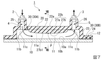
図7は、第2実施形態に係るコールドプレート1の断面構成図である。図8は、図7に示す矢視VIII-VIII断面図である。
図8に示すように、第2実施形態の樹脂カバー20は、天壁部22の下面22bに、凹部27aと凸部27bとを備えている。
Fig. 7 is a cross-sectional view of the
As shown in FIG. 8, the
凹部27aには、複数のフィン11の先端部が挿入されている。なお、フィン11の先端部とは、先端面11aと、その先端面11a近傍の両側面を含む部分を言う。
凸部27bは、複数の凹部27aの間に形成されている。凸部27bは、複数のフィン11の隙間に挿入されている。
The
The
凸部27bは、図7に示すように、フィン11が延びる長手方向に沿って、金属プレート10の板面10aに向かって凸状に湾曲している。具体的には、凸部27bは、フィン11の長手方向の中間位置Pにおいて、板面10aに最も近づき、中間位置Pから長手方向両側に離れるに従って、板面10aに対して徐々に離間していく流線形状の先端面27b1を有している。
As shown in Fig. 7, the
上記構成の第2実施形態によれば、図8に示すように、樹脂カバー20には、複数のフィン11の先端部が挿入される複数の凹部27aが形成されているため、フィン11と樹脂カバー20との融着に加え、フィン11と樹脂カバー20(凹部27a)とが嵌合することで、接合強度が向上し、樹脂カバー20の膨らむような変形を確実に抑制できる。また、フィン11が挿入される凹部27aがあることで、金属プレート10と樹脂カバー20の位置合わせが容易になり、接合が容易になる。
According to the second embodiment of the above configuration, as shown in FIG. 8, the
また、第2実施形態によれば、樹脂カバー20には、複数の凹部27aの間に、複数のフィン11の隙間に挿入される複数の凸部27bが形成され、図7に示すように、複数の凸部27bの先端面27b1は、複数のフィン11が延びる長手方向に沿って、金属プレート10に向かって凸状に湾曲している。この構成によれば、冷媒の流速が、フィン11の長手方向の中央部で増加するため、発熱部品が配置される金属プレート10の底板側を強制的に冷却することができる。
According to the second embodiment, the
(第3実施形態)
次に、本発明の第3実施形態について説明する。以下の説明において、上述の実施形態と同一又は同等の構成については同一の符号を付し、その説明を簡略若しくは省略する。
Third Embodiment
Next, a third embodiment of the present invention will be described. In the following description, the same or equivalent components as those in the above-described embodiment are denoted by the same reference numerals, and the description thereof will be simplified or omitted.
図9は、第3実施形態に係るコールドプレート1の平面図である。なお、図9においては、冷媒の流れを視認し易くするため、樹脂カバー20を二点鎖線で示している。図10は、図9に示す矢視X-X断面図である。図11は、図9に示す矢視XI-XI断面図である。
図10に示すように、第3実施形態のコールドプレート1は、樹脂カバー20に、金属プレート10に向かって突出した第2の凸部28が形成され、複数のフィン11の少なくとも一つの先端部には、第2の凸部28と嵌合する第2の凹部11dが形成されている。
Fig. 9 is a plan view of a
As shown in Figure 10, in the
第3実施形態の冷媒分配流路4及び冷媒回収流路5は、複数のフィン11が延びる長手方向における中央部に形成されている。第3実施形態の樹脂カバー20は、図9及び図11に示すように、冷媒分配流路4が形成された入口側マニホールド25と、冷媒回収流路5が形成された出口側マニホールド26と、を一体化した入出口マニホールド29を備えている。入出口マニホールド29の内部には、冷媒分配流路4と冷媒回収流路5との間を仕切る仕切壁29aが形成されている。
The
図9に示すように、冷媒分配流路4から流入した冷媒は、複数のフィン11の長手方向中央部から長手方向両端部に抜け、複数のフィン11の長手方向両端部と樹脂カバー20との隙間を流れ、複数のフィン11の形成範囲外に配置された冷媒回収流路5から回収される。
As shown in FIG. 9, the refrigerant that flows in from the
第2の凸部28は、冷媒分配流路4の両側に沿って、複数のフィン11と直交する方向に延在している。第2の凸部28は、図10に示すように、樹脂カバー20の天壁部22の下面22bより下方に突出している。
第2の凹部11dは、第2の凸部28に対応した形状を有している。第2の凹部11dの表面にも粗面化部30が形成されている。
The
The
上記構成の第3実施形態によれば、樹脂カバー20には、複数のフィン11の隙間に連通する冷媒分配流路4と、冷媒分配流路4に沿って延在すると共に、金属プレート10に向かって突出した第2の凸部28と、が形成され、複数のフィン11の少なくとも一つの先端部には、第2の凸部28と嵌合する第2の凹部11dが形成されているため、フィン11と樹脂カバー20との融着に加え、第2の凸部28と第2の凹部11dとが嵌合することで、接合強度が向上する。
According to the third embodiment of the above configuration, the
また、第2の凹部11dにも粗面化部30を形成し、粗面化部30の面積を増やすことで、フィン11と樹脂カバー20との融着部分における接合強度が向上する。さらに、冷媒の流入口である冷媒分配流路4においては、冷媒の圧力が高まり易くなるため、冷媒分配流路4に沿って第2の凸部28を設けることで、樹脂カバー20の膨らむような変形を効果的に抑制できる。
In addition, by forming a roughened
また、第3実施形態によれば、冷媒分配流路4は、複数のフィン11が延びる長手方向における中央部に形成されており、第2の凸部28も複数のフィン11が延びる長手方向における略中央部に配置されるため、樹脂カバー20の天壁部22がドーム状に膨らもうとする変形を確実に抑制できる。
In addition, according to the third embodiment, the
以上、本発明の好ましい実施形態を記載し説明してきたが、これらは本発明の例示的なものであり、限定するものとして考慮されるべきではないことを理解すべきである。追加、省略、置換、およびその他の変更は、本発明の範囲から逸脱することなく行うことができる。従って、本発明は、前述の説明によって限定されていると見なされるべきではなく、特許請求の範囲によって制限されている。 Although preferred embodiments of the present invention have been described and illustrated above, it should be understood that these are illustrative of the present invention and should not be considered as limiting. Additions, omissions, substitutions, and other modifications can be made without departing from the scope of the present invention. Thus, the present invention should not be considered as limited by the foregoing description, but rather by the scope of the claims.
例えば、上記実施形態では、複数のフィン11の全ての先端面11aに粗面化部30を形成している構成について説明したが、複数のフィン11の少なくとも一つの先端面11aに粗面化部30が形成されていればよい。また、金属プレート10は、先端面11aに粗面化部30が形成されているフィン11と、先端面11aに粗面化部30が形成されていないフィン11と、を交互に備えていても構わない。
For example, in the above embodiment, a configuration in which the roughened
また、例えば、上記実施形態では、金属プレート10と樹脂カバー20の周縁部が、加熱融着によって接合されている構成について説明したが、従来技術を応用し、金属プレート10と樹脂カバー20の周縁部が、樹脂による射出成形によって接合されている構成であっても構わない。また、金属プレート10と樹脂カバー20の周縁部が、ボルト及びナットなどの固定具によって締結固定されている構成であっても構わない。
In addition, for example, in the above embodiment, the peripheral portions of the
1…コールドプレート、4…冷媒分配流路、10…金属プレート、11…フィン、11a…先端面、11d…第2の凹部、12…周縁部、20…樹脂カバー、27a…凹部、27b…凸部、28…第2の凸部、30…粗面化部、30A…第1の粗面化部、30B…第2の粗面化部
REFERENCE SIGNS
Claims (5)
前記複数のフィンを覆う樹脂カバーと、を備え、
前記複数のフィンの少なくとも一つの先端面には、粗面化部が形成され、
前記粗面化部と前記樹脂カバーとが融着され、
前記樹脂カバーには、
前記複数のフィンの先端部が挿入される複数の凹部と、
前記複数の凹部の間に、前記複数のフィンの隙間に挿入される複数の凸部と、が形成され、
前記複数の凸部の先端面は、前記複数のフィンが延びる長手方向に沿って、前記金属プレートに向かって凸状に湾曲すると共に、前記複数のフィンの長手方向の中間位置において前記金属プレートに最も近づき、前記中間位置から長手方向両側に離れるに従って、前記金属プレートに対して徐々に離間していく流線形状を有する、コールドプレート。 A metal plate having a plurality of fins formed thereon;
a resin cover that covers the plurality of fins,
A roughened portion is formed on a tip surface of at least one of the plurality of fins,
The roughened portion and the resin cover are fused together,
The resin cover has
a plurality of recesses into which the tip portions of the plurality of fins are inserted;
a plurality of protrusions to be inserted into gaps between the plurality of fins are formed between the plurality of recesses,
a cold plate, wherein the tip surfaces of the multiple convex portions are convexly curved toward the metal plate along the longitudinal direction in which the multiple fins extend, and have a streamlined shape that is closest to the metal plate at a longitudinal intermediate position of the multiple fins and gradually moves away from the metal plate as it moves away from the intermediate position on both sides in the longitudinal direction.
前記複数のフィンの隙間に連通する冷媒分配流路と、
前記冷媒分配流路に沿って延在すると共に、前記金属プレートに向かって突出した第2の凸部と、が形成され、
前記複数のフィンの少なくとも一つの先端部には、前記第2の凸部と嵌合する第2の凹部が形成されている、請求項1または2に記載のコールドプレート。 The resin cover has
a refrigerant distribution passage communicating with gaps between the plurality of fins;
a second protrusion extending along the refrigerant distribution flow path and protruding toward the metal plate is formed,
3. The cold plate according to claim 1, wherein a tip portion of at least one of the plurality of fins is formed with a second recess portion adapted to fit with the second protrusion portion.
前記複数のフィンを覆う樹脂カバーと、を備え、
前記複数のフィンの少なくとも一つの先端面には、粗面化部が形成され、
前記粗面化部と前記樹脂カバーとが融着され、
前記樹脂カバーには、
前記複数のフィンの隙間に連通する冷媒分配流路と、
前記冷媒分配流路に沿って延在すると共に、前記金属プレートに向かって突出した第2の凸部と、が形成され、
前記複数のフィンの少なくとも一つの先端部には、前記第2の凸部と嵌合する第2の凹部が形成され、
前記第2の凹部にも、前記粗面化部が形成されている、コールドプレート。 A metal plate having a plurality of fins formed thereon;
a resin cover that covers the plurality of fins,
A roughened portion is formed on a tip surface of at least one of the plurality of fins,
The roughened portion and the resin cover are fused together,
The resin cover has
a refrigerant distribution passage communicating with gaps between the plurality of fins;
a second protrusion extending along the refrigerant distribution flow path and protruding toward the metal plate is formed,
At least one of the fins has a tip end formed with a second recess that fits into the second protrusion,
The second recess also has the roughened surface.
Priority Applications (3)
| Application Number | Priority Date | Filing Date | Title |
|---|---|---|---|
| JP2020178103A JP7601603B2 (en) | 2020-10-23 | 2020-10-23 | Cold Plate |
| US17/499,954 US20220128323A1 (en) | 2020-10-23 | 2021-10-13 | Cold plate and method for manufacturing cold plate |
| JP2024211561A JP2025023264A (en) | 2020-10-23 | 2024-12-04 | Cold plate and method for manufacturing the same |
Applications Claiming Priority (1)
| Application Number | Priority Date | Filing Date | Title |
|---|---|---|---|
| JP2020178103A JP7601603B2 (en) | 2020-10-23 | 2020-10-23 | Cold Plate |
Related Child Applications (1)
| Application Number | Title | Priority Date | Filing Date |
|---|---|---|---|
| JP2024211561A Division JP2025023264A (en) | 2020-10-23 | 2024-12-04 | Cold plate and method for manufacturing the same |
Publications (2)
| Publication Number | Publication Date |
|---|---|
| JP2022069115A JP2022069115A (en) | 2022-05-11 |
| JP7601603B2 true JP7601603B2 (en) | 2024-12-17 |
Family
ID=81258140
Family Applications (2)
| Application Number | Title | Priority Date | Filing Date |
|---|---|---|---|
| JP2020178103A Active JP7601603B2 (en) | 2020-10-23 | 2020-10-23 | Cold Plate |
| JP2024211561A Pending JP2025023264A (en) | 2020-10-23 | 2024-12-04 | Cold plate and method for manufacturing the same |
Family Applications After (1)
| Application Number | Title | Priority Date | Filing Date |
|---|---|---|---|
| JP2024211561A Pending JP2025023264A (en) | 2020-10-23 | 2024-12-04 | Cold plate and method for manufacturing the same |
Country Status (2)
| Country | Link |
|---|---|
| US (1) | US20220128323A1 (en) |
| JP (2) | JP7601603B2 (en) |
Families Citing this family (5)
| Publication number | Priority date | Publication date | Assignee | Title |
|---|---|---|---|---|
| US12446185B2 (en) * | 2021-06-22 | 2025-10-14 | Fujikura Ltd. | Cold plate |
| JP2023150887A (en) * | 2022-03-31 | 2023-10-16 | 三菱重工業株式会社 | Cooling device |
| JP2024087237A (en) * | 2022-12-19 | 2024-07-01 | 株式会社フジクラ | Cold Plate |
| JP2024115132A (en) | 2023-02-14 | 2024-08-26 | 株式会社フジクラ | Cold Plate |
| JP2025070860A (en) * | 2023-10-20 | 2025-05-02 | 株式会社日立製作所 | Cooling structure for power conversion device |
Citations (7)
| Publication number | Priority date | Publication date | Assignee | Title |
|---|---|---|---|---|
| JP2014079975A (en) | 2012-10-17 | 2014-05-08 | Nippon Light Metal Co Ltd | Method for manufacturing a composite hollow container and composite hollow container |
| JP2014192409A (en) | 2013-03-28 | 2014-10-06 | Fujitsu Ltd | Micro channel heat exchange device and electronic equipment |
| JP2016015381A (en) | 2014-07-01 | 2016-01-28 | 株式会社フジクラ | Cold plate |
| JP2018081997A (en) | 2016-11-15 | 2018-05-24 | 株式会社フジクラ | Cold plate |
| JP2018182043A (en) | 2017-04-12 | 2018-11-15 | 富士通株式会社 | Bonded body, method of manufacturing bonded body, cooling device, and information processing apparatus |
| WO2020138211A1 (en) | 2018-12-25 | 2020-07-02 | 三井化学株式会社 | Cooling unit, method for manufacturing cooling unit, and structure |
| US20200227341A1 (en) | 2019-01-11 | 2020-07-16 | Intel Corporation | Direct liquid micro jet (dlmj) structures for addressing thermal performance at limited flow rate conditions |
Family Cites Families (3)
| Publication number | Priority date | Publication date | Assignee | Title |
|---|---|---|---|---|
| JP4605009B2 (en) * | 2005-12-28 | 2011-01-05 | 三菱マテリアル株式会社 | Power module manufacturing method |
| JP2012004405A (en) * | 2010-06-18 | 2012-01-05 | Denso Corp | Cooler and method for manufacturing the same |
| CN204230382U (en) * | 2014-10-31 | 2015-03-25 | 比亚迪股份有限公司 | A kind of heating panel and electrokinetic cell system |
-
2020
- 2020-10-23 JP JP2020178103A patent/JP7601603B2/en active Active
-
2021
- 2021-10-13 US US17/499,954 patent/US20220128323A1/en active Pending
-
2024
- 2024-12-04 JP JP2024211561A patent/JP2025023264A/en active Pending
Patent Citations (7)
| Publication number | Priority date | Publication date | Assignee | Title |
|---|---|---|---|---|
| JP2014079975A (en) | 2012-10-17 | 2014-05-08 | Nippon Light Metal Co Ltd | Method for manufacturing a composite hollow container and composite hollow container |
| JP2014192409A (en) | 2013-03-28 | 2014-10-06 | Fujitsu Ltd | Micro channel heat exchange device and electronic equipment |
| JP2016015381A (en) | 2014-07-01 | 2016-01-28 | 株式会社フジクラ | Cold plate |
| JP2018081997A (en) | 2016-11-15 | 2018-05-24 | 株式会社フジクラ | Cold plate |
| JP2018182043A (en) | 2017-04-12 | 2018-11-15 | 富士通株式会社 | Bonded body, method of manufacturing bonded body, cooling device, and information processing apparatus |
| WO2020138211A1 (en) | 2018-12-25 | 2020-07-02 | 三井化学株式会社 | Cooling unit, method for manufacturing cooling unit, and structure |
| US20200227341A1 (en) | 2019-01-11 | 2020-07-16 | Intel Corporation | Direct liquid micro jet (dlmj) structures for addressing thermal performance at limited flow rate conditions |
Also Published As
| Publication number | Publication date |
|---|---|
| JP2025023264A (en) | 2025-02-14 |
| JP2022069115A (en) | 2022-05-11 |
| US20220128323A1 (en) | 2022-04-28 |
Similar Documents
| Publication | Publication Date | Title |
|---|---|---|
| JP7601603B2 (en) | Cold Plate | |
| US11243034B2 (en) | Injection-molded flexible cold plate | |
| CN203038910U (en) | Liquid-cooled cooling device | |
| US8593812B2 (en) | Heat exchanger, semiconductor device, method for manufacturing the heat exchanger, and method for manufacturing the semiconductor device | |
| CN101952064A (en) | Method of manufacturing a pipe coupling component, method of manufacturing a casing structural member, and pipe coupling structure for a hollow part | |
| JP2004286358A (en) | Core structure of heat exchanger | |
| US20180197833A1 (en) | Semiconductor device and manufacturing method of semiconductor device | |
| JP5880531B2 (en) | Cooler | |
| JP4698413B2 (en) | Liquid-cooled heat sink | |
| JP6730345B2 (en) | Cold plate | |
| JP7474629B2 (en) | Cold Plate | |
| JP2011228508A (en) | Power module | |
| JP4724435B2 (en) | Flat heat pipe and manufacturing method thereof | |
| JP7082036B2 (en) | How to make a radiator | |
| JP2021097134A (en) | Cooling device | |
| JP5589829B2 (en) | Heat exchanger | |
| JP2020088198A (en) | Radiator and cooler | |
| JP3577192B2 (en) | Cooling device for semiconductor device | |
| JP5650017B2 (en) | Segment for shield tunnel | |
| JP2011086805A (en) | Semiconductor device, and method of manufacturing the same | |
| RU184729U1 (en) | RADIATOR FOR COOLING ELECTRONIC DEVICES | |
| JP2690124B2 (en) | Method for manufacturing heat dissipation wall for oil-filled transformer | |
| JPH09246768A (en) | Boiling/cooling device | |
| JP2009030891A (en) | Plate laminate and manufacturing method thereof | |
| JP2025022638A (en) | Cooling member and cooling module |
Legal Events
| Date | Code | Title | Description |
|---|---|---|---|
| A621 | Written request for application examination |
Free format text: JAPANESE INTERMEDIATE CODE: A621 Effective date: 20230628 |
|
| A977 | Report on retrieval |
Free format text: JAPANESE INTERMEDIATE CODE: A971007 Effective date: 20240329 |
|
| A131 | Notification of reasons for refusal |
Free format text: JAPANESE INTERMEDIATE CODE: A131 Effective date: 20240409 |
|
| A521 | Request for written amendment filed |
Free format text: JAPANESE INTERMEDIATE CODE: A523 Effective date: 20240610 |
|
| A131 | Notification of reasons for refusal |
Free format text: JAPANESE INTERMEDIATE CODE: A131 Effective date: 20240820 |
|
| A521 | Request for written amendment filed |
Free format text: JAPANESE INTERMEDIATE CODE: A523 Effective date: 20241018 |
|
| TRDD | Decision of grant or rejection written | ||
| A01 | Written decision to grant a patent or to grant a registration (utility model) |
Free format text: JAPANESE INTERMEDIATE CODE: A01 Effective date: 20241105 |
|
| A61 | First payment of annual fees (during grant procedure) |
Free format text: JAPANESE INTERMEDIATE CODE: A61 Effective date: 20241205 |
|
| R150 | Certificate of patent or registration of utility model |
Ref document number: 7601603 Country of ref document: JP Free format text: JAPANESE INTERMEDIATE CODE: R150 |