JP7601706B2 - Animal rearing unit and animal rearing unit system - Google Patents
Animal rearing unit and animal rearing unit system Download PDFInfo
- Publication number
- JP7601706B2 JP7601706B2 JP2021082939A JP2021082939A JP7601706B2 JP 7601706 B2 JP7601706 B2 JP 7601706B2 JP 2021082939 A JP2021082939 A JP 2021082939A JP 2021082939 A JP2021082939 A JP 2021082939A JP 7601706 B2 JP7601706 B2 JP 7601706B2
- Authority
- JP
- Japan
- Prior art keywords
- unit
- animal
- animal rearing
- lid
- booth
- Prior art date
- Legal status (The legal status is an assumption and is not a legal conclusion. Google has not performed a legal analysis and makes no representation as to the accuracy of the status listed.)
- Active
Links
- 241001465754 Metazoa Species 0.000 title claims description 119
- 230000000384 rearing effect Effects 0.000 title claims description 61
- 238000003860 storage Methods 0.000 claims description 48
- 238000004378 air conditioning Methods 0.000 claims description 15
- 238000005192 partition Methods 0.000 claims description 14
- 230000007613 environmental effect Effects 0.000 claims description 12
- 238000003384 imaging method Methods 0.000 claims description 10
- 239000000463 material Substances 0.000 claims description 8
- 238000009423 ventilation Methods 0.000 claims description 5
- 238000012546 transfer Methods 0.000 description 19
- 244000052769 pathogen Species 0.000 description 12
- 238000003975 animal breeding Methods 0.000 description 8
- 208000035473 Communicable disease Diseases 0.000 description 6
- 238000010586 diagram Methods 0.000 description 6
- 208000015181 infectious disease Diseases 0.000 description 6
- 238000011160 research Methods 0.000 description 4
- 241000700159 Rattus Species 0.000 description 2
- 230000005540 biological transmission Effects 0.000 description 2
- 238000004140 cleaning Methods 0.000 description 2
- 230000001717 pathogenic effect Effects 0.000 description 2
- 238000009395 breeding Methods 0.000 description 1
- 230000001488 breeding effect Effects 0.000 description 1
- 238000013461 design Methods 0.000 description 1
- 239000000428 dust Substances 0.000 description 1
- 230000000694 effects Effects 0.000 description 1
- 238000012423 maintenance Methods 0.000 description 1
- 238000012986 modification Methods 0.000 description 1
- 230000004048 modification Effects 0.000 description 1
- 238000005096 rolling process Methods 0.000 description 1
- 239000007921 spray Substances 0.000 description 1
Images




Landscapes
- Housing For Livestock And Birds (AREA)
Description
本発明は、動物飼育ユニット及び動物飼育ユニットシステムに関するものである。 The present invention relates to an animal rearing unit and an animal rearing unit system.
例えば研究施設では、ラット等の動物が飼育されている。特許文献1には、動物の飼育を自動的に行う動物飼育システムが開示されている。特許文献1に開示された動物飼育システムは、ラックと、搬送用ロボットと、カメラを備えており、搬送用ロボットのハンドを用いて動物飼育用のケージの搬送を行う。
For example, animals such as rats are kept in research facilities.
ところで、特許文献1に開示された動物飼育システムのように複数の動物を飼育する設備では、動物が収容されたケージが隣接して複数収容されることが一般的である。しかしながら、動物愛護の観点及び動物の体調管理の観点からも動物に与えるストレスを低減させる必要がある。また、いずれかのケージに収容された動物が病原体に侵された場合には、他のケージに収容された動物に病原体が伝染することを抑止する必要がある。
Incidentally, in facilities for raising multiple animals, such as the animal rearing system disclosed in
本発明は、上述する問題点に鑑みてなされたもので、複数の動物が飼育可能な動物飼育ユニット及び動物飼育ユニットシステムにおいて、飼育する動物に与えるストレスを低減すると共に、飼育する動物が感染症にかかった場合に他の動物への病原体の伝染を抑止することを目的とする。 The present invention was made in consideration of the above-mentioned problems, and aims to reduce the stress on animals kept in an animal rearing unit and animal rearing unit system capable of rearing multiple animals, and to prevent the transmission of pathogens to other animals if an animal becomes infected with an infectious disease.
本発明は、上記課題を解決するための手段として、以下の構成を採用する。 The present invention adopts the following configuration as a means for solving the above problems.
本発明の第1の態様は、動物飼育ユニットであって、内部空間と外部空間とを隔離するチャンバと、上記チャンバの内部空間に走行可能に配置されると共に動物の収容ケージを移動する搬送ユニットと、上記搬送ユニットの移動空間に面する開口を有すると共に上記収容ケージが載置可能な複数の載置ブースと、上記載置ブース同士の間に配置された隔壁とを備えるという構成を採用する。 The first aspect of the present invention is an animal rearing unit that includes a chamber that separates an internal space from an external space, a transport unit that is arranged to be movable in the internal space of the chamber and that moves animal containment cages, a number of loading booths that have openings facing the movement space of the transport unit and in which the containment cages can be placed, and partitions that are arranged between the loading booths.
本発明の第2の態様は、上記第1の態様において、上記載置ブースの上記開口を開閉する蓋部を備え、上記搬送ユニットが、上記収容ケージを移動させるケージ移動部と、上記蓋部を着脱かつ保持可能な蓋保持部とを備えるという構成を採用する。 The second aspect of the present invention is the first aspect, further comprising a lid section for opening and closing the opening of the loading booth, and the transport unit is provided with a cage moving section for moving the storage cage and a lid holding section capable of detachably holding the lid section.
本発明の第3の態様は、上記第2の態様において、上記搬送ユニットの移動空間及び上記載置ブースのいずれかあるいは両方の環境を個別に調整可能な環境調整ユニットを備えるという構成を採用する。 The third aspect of the present invention is the second aspect described above, but with an environmental adjustment unit capable of individually adjusting the environment of either or both of the movement space of the transport unit and the loading booth.
本発明の第4の態様は、上記第3の態様において、上記環境調整ユニットとして、上記搬送ユニットの移動空間に清浄した空気を供給する空調ユニットを備え、上記蓋部で上記開口が閉じられた状態で、上記搬送ユニットの移動空間から上記載置ブースの内部空間に通気可能な通気流路が設けられているという構成を採用する。 The fourth aspect of the present invention is the third aspect, in which the environmental adjustment unit is provided with an air conditioning unit that supplies purified air to the movement space of the transport unit, and an air flow path is provided that allows ventilation from the movement space of the transport unit to the internal space of the loading booth when the opening is closed by the lid.
本発明の第5の態様は、上記第3または第4の態様において、上記環境調整ユニットとして、上記載置ブースに配置されると共に上記載置ブースの内部空間の空気を上記チャンバの外部に排気する排気ユニットを備えるという構成を採用する。 The fifth aspect of the present invention is the third or fourth aspect, in which the environmental adjustment unit is provided with an exhaust unit that is disposed in the loading booth and exhausts air from the internal space of the loading booth to the outside of the chamber.
本発明の第6の態様は、上記第2~第5いずれかの態様において、上記蓋部が、赤外線が透過可能な材料で形成されているという構成を採用する。 The sixth aspect of the present invention is any one of the second to fifth aspects, in which the lid is made of a material that is transparent to infrared rays.
本発明の第7の態様は、上記第1~第6いずれかの態様において、上記搬送ユニットは、上記収容ケージを移動する場合に上記収容ケージの側面の少なくとも一部を覆う被覆部を備えるという構成を採用する。 A seventh aspect of the present invention is any one of the first to sixth aspects, in which the transport unit is provided with a covering portion that covers at least a portion of the side surface of the storage cage when the storage cage is moved.
本発明の第8の態様は、上記第7の態様において、上記搬送ユニットが、上記収容ケージを移動する場合に上記収容ケージの下面を下方から支持する下面支持部を備えるという構成を採用する。 The eighth aspect of the present invention is the seventh aspect, in which the transport unit is provided with a bottom support portion that supports the bottom surface of the storage cage from below when the storage cage is moved.
本発明の第9の態様は、上記第1~第8いずれかの態様において、上記搬送ユニットが、上記載置ブースの内部空間の上記動物を撮像する撮像部を備えるという構成を採用する。 A ninth aspect of the present invention is any one of the first to eighth aspects, in which the transport unit is provided with an imaging unit that images the animal in the internal space of the placement booth.
本発明の第10の態様は、上記第1~第9いずれかの態様において、上記チャンバに併設されると共に上記収容ケージに対する作業を外部から視認可能な作業ユニットを備えるという構成を採用する。 The tenth aspect of the present invention is any one of the first to ninth aspects, and is configured to include a working unit that is provided next to the chamber and allows the work performed on the storage cage to be visually observed from the outside.
本発明の第11の態様は、動物飼育ユニットシステムであって、複数の第1~第10のいずれかの態様における動物飼育ユニットを備えるという構成を採用する。 An eleventh aspect of the present invention is an animal rearing unit system that employs a configuration including a plurality of animal rearing units according to any one of the first to tenth aspects.
本発明は、搬送ユニットを用いてチャンバ内で収容ケージの移動が可能である。このため、チャンバ内の動物に感染症が発生した場合に、チャンバの外部に病原体が漏出することを抑止することが可能となり、研究設備等における他の動物に病原体が伝染することを抑止できる。さらに、本発明は、載置ブース同士の間に隔壁が配置されている。このため、隔壁によって、他の載置ブースの動物の動き、物音、病原体が伝わることを抑止することができる。したがって、本発明によれば、飼育する動物に与えるストレスを低減すると共に、飼育する動物が感染症にかかった場合に他の動物への病原体の伝染を抑止することが可能となる。 The present invention allows the movement of the housing cages within the chamber using a transport unit. Therefore, if an animal in the chamber develops an infectious disease, it is possible to prevent pathogens from leaking out of the chamber, and to prevent the pathogens from spreading to other animals in research facilities, etc. Furthermore, the present invention provides partitions between the loading booths. Therefore, the partitions can prevent the movement, noise, and pathogens of animals in other loading booths from being transmitted. Therefore, the present invention reduces stress on the animals being kept, and makes it possible to prevent the spread of pathogens to other animals if an animal being kept becomes infected with an infectious disease.
以下、図面を参照して、本発明に係る動物飼育ユニット及び動物飼育ユニットシステムの一実施形態について説明する。 Below, an embodiment of an animal rearing unit and an animal rearing unit system according to the present invention will be described with reference to the drawings.
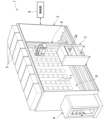
本実施形態の動物飼育ユニット1は、例えば、研究施設等において、マウスやラット等の動物Xを収容ケージYに収容した状態で飼育するための装置として用いられる。図1は、本実施形態の動物飼育ユニット1の概略構成を示す斜視図である。図2は、本実施形態の動物飼育ユニット1のチャンバ2の内部を露出させた状態の概略構成を示す斜視図である。
The
図1及び図2に示すように、本実施形態の動物飼育ユニット1は、チャンバ2と、キャビネット3と、エアシャワー4と、空調ユニット5(環境調整ユニット)と、ラック6と、蓋部7と、搬送ユニット8と、制御部9とを備えている。
As shown in Figures 1 and 2, the
チャンバ2は、ラック6、蓋部7及び搬送ユニット8を収容しており、内部空間と外部空間とを隔離する大型の容器状の部材である。本実施形態においてチャンバ2は、平面視形状が長辺と短辺とを有する長方形とされた形状に形成されている。
The
なお、搬送ユニット8は、後述するようにチャンバ2の内部にてチャンバ2の平面視における長辺に沿った方向に走行する。このため、以下の説明においては、チャンバ2の長手方向(長辺に沿う方向)を走行方向と称する。また、搬送ユニット8は、後述する収容ケージYを移載する場合に、収容ケージYをチャンバ2の平面視における短辺に沿った方向に移動する。このため、以下の説明においては、チャンバ2の短手方向(短辺に沿う方向)を移載方向と称する。さらに、走行方法及び移載方向に直交する方向を上下方向と称する。
As described below, the
キャビネット3は、走行方向における略中央位置にてチャンバ2の側壁に設けられている。キャビネット3は、図1に示すように、チャンバ2の下部に設けられており、チャンバ2の側壁からチャンバ2の外側に向けて突出して設けられている。
このキャビネット3は、内部空間がチャンバ2の内部空間と接続されており、チャンバ2の内部から搬出された収容ケージYが載置可能とされた部位である。このようなキャビネット3には、ラック6に収容された収容ケージYが搬送ユニット8によって移動され、移載される。また、キャビネット3に載置された収容ケージYは、搬送ユニット8によって移動され、ラック6に移載される。
The cabinet 3 is provided at a substantially central position in the traveling direction on the side wall of the
The internal space of this cabinet 3 is connected to the internal space of the
また、キャビネット3の正面側には、開閉可能な窓部3aが設けられている。このため、窓部3aを閉めた状態で収容ケージYに収容された動物Xをキャビネット3の外部から観察することが可能である。また、窓部3aを半開放させた状態で、例えば作業者がキャビネット3の外部からキャビネット3の内部に手のみを差し入れて、収容ケージYに収容された動物X等に対する作業を行うことが可能である。また、窓部3aを開放させた状態で、収容ケージYをキャビネット3の出し入れを行うことが可能である。
In addition, the front side of the cabinet 3 is provided with an openable and
なお、キャビネット3は、例えば、内部空間に2つの収容ケージYを走行方向に2つ並べて載置可能な大きさに形成されている。このようなキャビネット3の内部空間と、チャンバ2の内部空間との境界部には、開閉可能な蓋部7が設けられている。この蓋部7は、搬送ユニット8が備える後述の蓋開閉ユニット8dによって開閉可能に形成されている。なお、キャビネット3は、クリーンベンチまたはグローブボックスであっても良い。さらに、キャビネット3は、パスボックス機能を有しても良い。つまり、本実施形態の動物飼育ユニット1は、チャンバ2に併設されると共に収容ケージYに対する作業を外部から視認可能な作業ユニットを備えることが好ましい。
The cabinet 3 is formed to be large enough to accommodate two storage cages Y, for example, side by side in the travel direction in the internal space. An openable and
エアシャワー4は、走行方向におけるチャンバ2の一端側に設けられている。このエアシャワー4は、チャンバ2の下部に設けられており、チャンバ2の側壁からチャンバ2の外側に突出して取り付けられている。
The
このエアシャワー4は、内部空間がチャンバ2の内部空間と接続されており、エアシャワー4の内部空間を介してチャンバ2の内部空間に作業者が出入り可能となるように形成されている。つまり、エアシャワー4は、チャンバ2への出入口として機能する。このようなエアシャワー4は、内部空間に向けて洗浄気流を噴射可能に形成されており、洗浄気流を用いて内部空間の作業者に付着した異物等を除去する。
The internal space of this
空調ユニット5は、チャンバ2の上部に配置されており、チャンバ2の内部空間に対して清浄した空気を供給する。例えば、図1及び図2に示すように、空調ユニット5は、チャンバ2の上部に対して複数設けられている。各々の空調ユニット5は、外気に含まれる異物を除去するために、例えばHEPA(High Efficiency Particulate Air Filter)フィルタ等のフィルタを内蔵している。
The
これらの空調ユニット5は、チャンバ2の内部空間のうち、搬送ユニット8の走行空間(移動空間)に対して清浄した空気を供給する。このような清浄した空気は、搬送ユニット8の走行空間から、この走行空間に面して設けられた後述の載置ブース6aの内部に供給される。なお、載置ブース6aの内部の空気は、フィルタ等が設けられた不図示の排気流路を介して、チャンバ2の外部に排出される。このような空調ユニット5は、搬送ユニット8の走行空間及び後述の載置ブース6aのうち搬送ユニット8の走行空間の環境を調整する環境調整ユニットである。
These
ラック6は、チャンバ2の内部空間に配置されており、収容ケージYが載置可能な複数の載置ブース6aを備えている。本実施形態においては、チャンバ2の内部に、走行方向に延伸する走行空間が設けられている。この走行空間は、搬送ユニット8が走行することによって移動される空間である。このような走行空間を移載方向にて挟むようにして、2つのラック6が設けられている。なお、本実施形態において各々のラック6は、チャンバ2の側壁と一体的に設けられている。ただし、各々のラック6は、チャンバ2の側壁と別体として設けられていても良い。
The
図3は、ラック6の模式的な断面図であり、(a)が鉛直断面図であり、(b)が水平断面図である。この図に示すように、各々のラック6には、上下方向かつ走行方向に配列された複数の載置ブース6aが設けられている。各々の載置ブース6aは、走行空間に面する開口6a1を有している。各々の載置ブース6aには、開口6a1を介して収容ケージYが出し入れ可能とされている。
Figure 3 is a schematic cross-sectional view of the
本実施形態において各々の載置ブース6aは、単一の収容ケージYが収容可能な大きさに形成されている。各々の載置ブース6aの床面には、収容ケージYを載置する一対の脚部6bが設けられている。各々の脚部6bは、移載方向に沿って直線状に延伸されている。これらの脚部6bは、走行方向にて離間して配置されており、収容ケージYと載置ブース6aの床面との間に、搬送ユニット8の後述する下面支持板部8g2が挿入可能な隙間を形成している。
In this embodiment, each
なお、図示は省略しているが、載置ブース6aの内部には、載置ブース6aの内部を照らす照明装置(環境調整ユニット)が配置されていても良い。また、載置ブース6aの内部には、載置ブース6aの内部温度を調整する個別空調ユニット(環境調整ユニット)が配置されていても良い。このような照明装置及び個別空調ユニットは、搬送ユニット8の走行空間及び載置ブース6aのうち載置ブース6aの各々の環境を調整する環境調整ユニットである。
Although not shown in the figure, a lighting device (environmental adjustment unit) that illuminates the inside of the
また、このようなラック6は、載置ブース6a同士の間に配置される隔壁6cが設けられている。隔壁6cは、載置ブース6aの側壁、底壁、天壁として機能する。このような隔壁6cが設けられることによって、隣接する載置ブース6a同士の間での音の伝搬を抑制する遮音効果が得られる。このため、ある載置ブース6aに収容された動物Xに、他の載置ブース6aに収容された動物Xから発せられた音が伝わることを隔壁6cによって抑止することができる。
In addition, such a
また、隔壁6cによって、隣接する載置ブース6a同士の間で埃や病原体が移動することを防止することが可能となる。このため、載置ブース6aの内部環境が他の載置ブース6aの内部環境によって影響を受けることを防止することが可能となる。
The
また、このような隔壁6cは、例えば可視光を遮る遮光性を有している。隔壁6cが遮光性を有することによって、載置ブース6aの内部の動物Xが他の載置ブース6aの動物Xの動きを視認することを防止し、他の載置ブース6aの内部での動きが動物Xに対してストレスを与えることを抑止することが可能となる。
Furthermore,
蓋部7は、載置ブース6aの開口6a1を開閉する部材である。蓋部7は、載置ブース6aの各々に対して設けられている。各々の蓋部7は、不図示の係止機構等によってラック6に対して着脱可能に係止されている。このような蓋部7は、搬送ユニット8の後述する蓋開閉ユニット8dによって着脱可能に設けられている。
The
また、図3に示すように、各々の蓋部7は、開口6a1を閉じる状態において、ラック6との間に隙間Sが形成される大きさに形成されている。この隙間Sは、蓋部7で開口6a1が閉じられた状態で、搬送ユニット8の走行空間から載置ブース6aの内部に通気可能な通気流路として用いられる。つまり、空調ユニット5から搬送ユニット8の走行空間に供給された清浄空気は、隙間Sを介して載置ブース6aの内部に供給される。
As shown in FIG. 3, each
このような蓋部7は、例えば可視光を遮る遮光性を有することが好ましい。蓋部7の全体が遮光性を有する材料で形成されていても良い。また、透光性を有する材料によって形成された部材を、遮光性を有する部材で被覆することで蓋部7を形成しても良い。このように蓋部7が可視光を遮る遮光性を有することによって、載置ブース6aの内部の動物Xが搬送ユニット8の動きを視認することを防止し、搬送ユニット8の動きが動物Xに対してストレスを与えることを抑止することが可能となる。
Such a
さらに蓋部7は、赤外線が透過可能な材料で形成することも可能である。蓋部7が赤外線を透過する材料で形成されている場合には、蓋部7を閉じた状態で、搬送ユニット8の走行空間から動物Xの様子を赤外線カメラで撮像することが可能となる。このため、動物Xにストレスを与えることなく動物Xの撮像を行うことが可能となる。
Furthermore, the
なお、蓋部7は、載置ブース6aに限られず、キャビネット3の内部空間とチャンバ2の内部空間との境界部にも設けられている。このキャビネット3の内部空間とチャンバ2の内部空間との境界部に設けられる蓋部7は、例えばキャビネット3に対して係止されている。
The
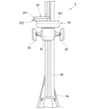
搬送ユニット8は、載置ブース6aとキャビネット3との間、あるいは、載置ブース6a同士の間にて収容ケージYを移載する。図4は、走行方向から見た搬送ユニット8の概略構成を示す正面図である。この図に示すように、搬送ユニット8は、台車部8aと、マスト8bと、昇降部8cと、蓋開閉ユニット8d(蓋保持部)と、移載ユニット8e(ケージ移動部)と、撮像ユニット8fとを備えている。
The
台車部8aは、車輪を介してチャンバ2の床面と接地されており、車輪の転動によってチャンバ2の床面上を移動可能な部位である。この台車部8aは、例えば不図示の走行モータの動力によって制御部9の制御の下、走行方向に移動可能に形成されている。このような台車部8aは、マスト8b、昇降部8c、蓋開閉ユニット8d、移載ユニット8e、及び撮像ユニット8fを直接的あるいは間接的に下方から支持する。
The
マスト8bは、台車部8aに立設されており、昇降部8cが昇降する場合のガイドとして用いられる。昇降部8cは、マスト8bに対して昇降可能に設けられた部位であり、例えば不図示の昇降モータの動力によって制御部9の制御の下に昇降可能に形成されている。
The
蓋開閉ユニット8dは、昇降部8cの移載方向における両端側に各々設けられている。つまり、本実施形態の蓋開閉ユニット8dは、昇降部8cに対して2つ設けられている。一方の蓋開閉ユニット8dは、2つのラック6のうち一方のラック6に対向するように配置されている。また、他方の蓋開閉ユニット8dは、他方のラック6に対向するように配置されている。
The lid opening/
各々の蓋開閉ユニット8dは、真空チャックを有しており、真空チャックを用いて蓋部7を吸着する。蓋開閉ユニット8dは、蓋部7を吸着した状態で、蓋部7の保持、蓋部7のラック6に対する着脱を行う。これらの蓋開閉ユニット8dは、制御部9の制御の下に、蓋部7の保持、蓋部7のラック6に対する着脱を行う。なお、真空チャックに換えて、鍵爪状の把持機構を蓋開閉ユニット8dに設け、蓋部7に把持機構が嵌合可能な溝状の嵌合部を設けるようにしても良い。
Each lid opening/
移載ユニット8eは、昇降部8cの上部に接続されており、搬送ユニット8と載置ブース6aとの間、搬送ユニット8とキャビネット3との間にて収容ケージYを移動する。図5は、移載ユニット8eを含む拡大斜視図である。この図に示すように、移載ユニット8eは、ハンドユニット8gを備えている。このハンドユニット8gは、収容ケージYの側面に当接される一対の遮光板部8g1(被覆部)と、収容ケージYを下方から支持する下面支持板部8g2(下面支持部)とを有している。
The
これらの遮光板部8g1及び下面支持板部8g2は、移載ユニット8eのベース部8e1に対して、移載方向における両側に対して延出可能に設けられている。つまり、遮光板部8g1及び下面支持板部8g2は、一方側のラック6の載置ブース6aの内部空間と、他方側のラック6の載置ブース6aの内部空間のいずれにも先端部を進入可能に形成されている。
The light shielding plate 8g1 and the lower support plate 8g2 are provided so as to be extendable on both sides in the transfer direction relative to the base 8e1 of the
2つの遮光板部8g1は、走行方向に離間して対向配置されている。これらの遮光板部8g1は、収容ケージYを間に配置可能な寸法で離間されている。これらの遮光板部8g1は、不図示の移動機構によって走行方向に移動可能に設けられている。図6は、遮光板部8g1及び下面支持板部8g2を含む模式図である。この図に示すように、2つの遮光板部8g1は、間に収容ケージYが互いに近接する方向に移動されることで、収容ケージYの側面に当接することが可能である。なお、これらの遮光板部8g1を収容ケージYに押圧あるいは係止等することによって遮光板部8g1によって収容ケージYを支持するようにしても良い。 The two light-shielding plate portions 8g1 are arranged facing each other with a space between them in the running direction. These light-shielding plate portions 8g1 are spaced apart to a dimension that allows the storage cage Y to be placed between them. These light-shielding plate portions 8g1 are provided so as to be movable in the running direction by a moving mechanism (not shown). FIG. 6 is a schematic diagram including the light-shielding plate portions 8g1 and the lower support plate portion 8g2. As shown in this figure, the two light-shielding plate portions 8g1 can abut against the side of the storage cage Y by moving the storage cage Y in a direction approaching each other between them. Note that the light-shielding plate portions 8g1 may be pressed against or engaged with the storage cage Y to support the storage cage Y.
このような遮光板部8g1は、可視光を遮る遮光性を有しており、収容ケージYが搬送ユニット8によって移動される場合に、収容ケージYの側面の少なくとも一部を覆う。このように収容ケージYの側面が覆われることによって、収容ケージYの内部の動物Xが収容ケージYの外側を視認することを抑止し、動物Xに与えるストレスを軽減することが可能になる。
Such a light-shielding plate portion 8g1 has a light-shielding property that blocks visible light, and covers at least a portion of the side surface of the containment cage Y when the containment cage Y is moved by the
下面支持板部8g2は、載置ブース6aの2つの脚部6bの間に進入可能な幅寸法で形成されており、収容ケージYの下面に対して当接することが可能である。収容ケージYは、搬送ユニット8によって移動される場合には、下面支持板部8g2によって下方から支持される。収容ケージYの床に遮光性の床敷が設けられている場合には、下面支持板部8g2は必ずしも遮光性を有している必要はない。ただし、収容ケージYの床部が可視光を透光する場合には、下面支持板部8g2に遮光性を付与することが好ましい。これによって下面支持板部8g2を被覆部として機能させ、動物Xに収容ケージYの下方が視認されることを抑止することが可能となる。
The lower support plate portion 8g2 is formed with a width dimension that allows it to enter between the two
撮像ユニット8fは、昇降部8cに支持されて、移載ユニット8eの上方に配置されている。この撮像ユニット8fは、鉛直軸を中心として水平面内で回転可能であると共に水平方向に伸縮可能なアーム部8f1と、アーム部8f1の先端に設けられた赤外線カメラ8f2(撮像部)とを備えている。
The
アーム部8f1は、例えば蓋部7が取り外されて載置ブース6aが開口された場合に、制御部9の制御の下に、赤外線カメラ8f2を載置ブース6aの内部空間に進入させる。赤外線カメラ8f2は、制御部9の制御の下に、動物Xを撮像し、撮像データを出力する。
For example, when the
制御部9は、エアシャワー4、空調ユニット5及び搬送ユニット8を制御する。制御部9は外部から指令信号を入力可能とされており、指令信号や予め記憶されたプログラム等に基づいて搬送ユニット8等を制御することによって、収容ケージYを移動する。
The
なお、本実施形態の動物飼育ユニット1は、作業者が指令信号等を入力するための操作部、撮像ユニット8fで取得された画像等を表示する表示部、操作する作業者を識別するカードリーダ等を備えていても良い。
The
例えば、このような本実施形態の動物飼育ユニット1において、載置ブース6aに載置された収容ケージYをキャビネット3まで移動させる場合には、制御部9は、搬送ユニット8の台車部8aを制御することにより、搬送ユニット8を走行させて、移動対象の収容ケージYが収容された載置ブース6aに正対するように搬送ユニット8を移動する。
For example, in the
続いて、制御部9は、搬送ユニット8に昇降部8cを昇降させ、移動対象の収容ケージYが収容された載置ブース6aを閉鎖する蓋部7に蓋開閉ユニット8dを対向配置させる。また、制御部9は、蓋開閉ユニット8dに蓋部7をラック6から脱離させると共に蓋部7を保持させる。
The
続いて、制御部9は、ハンドユニット8gが収容ケージYの正面に配置されるように昇降部8cを下降させる。ハンドユニット8gが収容ケージYの正面に配置されると、制御部9は、遮光板部8g1及び下面支持板部8g2が載置ブース6aに進入されるように移載ユニット8eを制御し、赤外線カメラ8f2が載置ブース6aに進入されるように撮像ユニット8fを制御する。
Then, the
続いて、制御部9は、遮光板部8g1に収容ケージYを覆わせ、下面支持板部8g2に収容ケージYを支持させ、赤外線カメラに収容ケージYに収容された動物Xを撮像させる。さらに、制御部9は、ハンドユニット8gによって収容ケージYを載置ブース6aから搬送ユニット8に移載させる。その後、制御部9は、昇降部8c及び蓋開閉ユニット8dを制御して、蓋部7を元の位置に戻す。
The
続いて、制御部9は、搬送ユニット8を必要に応じて走行させてキャビネット3に正対させる。制御部9は、昇降部8cを昇降させてキャビネット3に設けられた蓋部7に蓋開閉ユニット8dを対向配置させる。また、制御部9は、蓋開閉ユニット8dに蓋部7をキャビネット3から脱離させると共に蓋部7を保持させる。
The
続いて、制御部9は、ハンドユニット8gがキャビネット3の内部空間に正対されるように昇降部8cを下降させる。ハンドユニット8gがキャビネット3の内部空間の正面に配置されると、制御部9は、遮光板部8g1及び下面支持板部8g2がキャビネット3の内部空間に進入されるように移載ユニット8eを制御し、収容ケージYを載置させる。その後、制御部9は、搬送ユニット8に蓋部7を元の位置にもどさせ、初期位置等に復帰させる。
Then, the
以上のように本実施形態の動物飼育ユニット1は、内部空間と外部空間とを隔離するチャンバ2を有する。また、動物飼育ユニット1は、チャンバ2の内部空間に走行可能に配置されると共に動物Xの収容ケージYを移動する搬送ユニット8を備える。また、動物飼育ユニット1は、搬送ユニット8の移動空間に面する開口6a1を有すると共に収容ケージYが載置可能な複数の載置ブース6aを備える。また、動物飼育ユニット1は、載置ブース6a同士の間に配置された隔壁6cを備える。
As described above, the
このような本実施形態の動物飼育ユニット1は、搬送ユニット8を用いてチャンバ2内で収容ケージYの移動が可能である。このため、チャンバ2内の動物Xに感染症が発生した場合に、チャンバ2の外部に病原体が漏出することを抑止することが可能となり、研究設備等における他の動物Xに病原体が伝染することを抑止できる。さらに、本実施形態の動物飼育ユニット1は、載置ブース6a同士の間に隔壁6cが配置されている。このため、隔壁6cによって、他の載置ブース6aの動物Xの動き、物音、病原体が伝わることを抑止することができる。したがって、本実施形態の動物飼育ユニット1によれば、飼育する動物Xに与えるストレスを低減すると共に、飼育する動物Xが感染症にかかった場合に他の動物Xへの病原体の伝染を抑止することが可能となる。
The
また、本実施形態の動物飼育ユニット1は、載置ブース6aの開口6a1を開閉する蓋部7を備えている。また、搬送ユニット8が、収容ケージYを移動させる移載ユニット8eと、蓋部7を着脱かつ保持可能な蓋開閉ユニット8dとを備える。このような本実施形態の動物飼育ユニット1によれば、搬送ユニット8によって、蓋部7の着脱及び保持を行うと共に、収容ケージYの移動を行うことが可能となる。
The
また、本実施形態の動物飼育ユニット1は、搬送ユニット8の移動空間に清浄した空気を供給する空調ユニット5を備えている。また、動物飼育ユニット1は、蓋部7で開口6a1が閉じられた状態で、搬送ユニット8の移動空間から載置ブース6aの内部空間に通気可能な隙間Sが設けられている。このため、空調ユニット5から供給される清浄した空気を載置ブース6aに供給することが可能となる。
The
また、本実施形態の動物飼育ユニット1は、蓋部7が、赤外線が透過可能な材料で形成されていても良い。蓋部7を赤外線が透過可能な材料で形成することで、蓋部7の外側から赤外線に基づいて動物Xを観察することが可能となる。したがって、動物Xに観察していることを視認されることを抑止し、より動物Xに与えるストレスを低減させることが可能となる。
In addition, in the
また、本実施形態の動物飼育ユニット1では、搬送ユニット8は、収容ケージYを移動する場合に収容ケージYの側面の少なくとも一部を覆う遮光板部8g1を備える。このため、収容ケージYを搬送ユニット8で移動させる場合に、遮光板部8g1によって収容ケージYの側面を覆うことが可能である。このように収容ケージYの側面が覆われることによって、収容ケージYの内部の動物Xが収容ケージYの外側を視認することを抑止し、動物Xに与えるストレスを軽減することが可能になる。
In addition, in the
また、本実施形態の動物飼育ユニット1は、搬送ユニット8が、収容ケージYを移動する場合に収容ケージYの下面を下方から支持する下面支持板部8g2を備えている。このため、遮光板部8g1で収容ケージYの側面を覆った状態で収容ケージYを安定的に支持することが可能となる。
In addition, in the
また、本実施形態の動物飼育ユニット1は、搬送ユニット8が、載置ブース6aの内部空間の動物Xを撮像する赤外線カメラ8f2を備えている。このため、動物Xが床敷の内部に潜り込んでいるような場合であっても、動物Xの様子を撮像することができる。さらに、蓋部7が赤外線を透過する場合には、蓋部7を閉じたまま動物Xの様子を撮像することが可能である。
In addition, in the
以上、添付図面を参照しながら本発明の好適な実施形態について説明したが、本発明は、上記実施形態に限定されないことは言うまでもない。上述した実施形態において示した各構成部材の諸形状や組み合わせ等は一例であって、本発明の趣旨から逸脱しない範囲において設計要求等に基づき種々変更可能である。 The above describes a preferred embodiment of the present invention with reference to the attached drawings, but it goes without saying that the present invention is not limited to the above embodiment. The shapes and combinations of the components shown in the above embodiment are merely examples, and various modifications can be made based on design requirements, etc., without departing from the spirit of the present invention.
図7は、動物飼育ユニット1の変形例が備える載置ブース6aを含む模式図である。この図に示すように、図7に示す変形例においては、排気ユニット10(環境調整ユニット)が設けられている。この排気ユニット10は、各々の載置ブース6aに設けられた排気装置10aと、複数の排気装置10aが接続された排気流路10bとを備えている。このような排気ユニット10を備える変形例によれば、排気装置10aを駆動することによって、載置ブース6aの内部の空気を強制的に載置ブース6aの外部に排気することが可能となる。また、例えば、制御部9の制御の下、蓋部7を開放する載置ブース6aに設置された排気装置10aの排気量を増大させるようにしても良い。また、制御部9の制御の下、蓋部7を開放する場合に、蓋部7を開放する載置ブース6aに設置された排気装置10aを駆動するようにしても良い。これによって、載置ブース6aの内部の空気が搬送ユニット8の移動空間に漏出し、他の載置ブース6aに流入することをより確実に抑止することが可能となる。このような排気ユニット10は、搬送ユニット8の走行空間及び載置ブース6aのうち載置ブース6aの各々の環境を調整する環境調整ユニットである。
Figure 7 is a schematic diagram including a
図8は、複数の動物飼育ユニット1を備える動物飼育ユニットシステム100の概略構成を示す模式図である。この図に示すように、動物飼育ユニットシステム100は、例えば統括制御装置20によって統括的に制御される。このような複数の動物飼育ユニット1を備える動物飼育ユニットシステム100によれば、各々の動物飼育ユニットシステム100は独立していることから、各々の動物飼育ユニットシステム100の飼育環境はお互い影響しない。このため、いずれかの動物飼育ユニット1に感染症が発生した場合や、いずれかの動物飼育ユニット1のメンテナンスを行う場合等であっても、他の動物飼育ユニット1における飼育を停止することなく対応することが可能である。
Figure 8 is a schematic diagram showing the general configuration of an animal
なお、上記実施形態においては、下面支持板部8g2によって収容ケージYの下面を下方から支持する構成について説明した。しかしながら、本発明はこれに限定されるものではない。例えば、下面支持板部8g2に換えて、収容ケージYの側面を支持する側面支持部を備える構成を採用することも可能である。 In the above embodiment, a configuration has been described in which the lower surface of the storage cage Y is supported from below by the lower surface support plate portion 8g2. However, the present invention is not limited to this. For example, it is also possible to adopt a configuration in which, instead of the lower surface support plate portion 8g2, a side support portion is provided to support the side surface of the storage cage Y.
1……動物飼育ユニット、2……チャンバ、3……キャビネット、4……エアシャワー、5……空調ユニット、6……ラック、6a……載置ブース、6a1……開口、6b……脚部、6c……隔壁、7……蓋部、8……搬送ユニット、8a……台車部、8b……マスト、8c……昇降部、8d……蓋開閉ユニット(蓋保持部)、8e……移載ユニット(ケージ移動部)、8f……撮像ユニット、8f1……アーム部、8f2……赤外線カメラ、8g……ハンドユニット、8g1……遮光板部(被覆部)、8g2……下面支持板部(下面支持部)、9……制御部、10……排気ユニット、10a……排気装置、10b……排気流路、20……統括制御装置、100……動物飼育ユニットシステム、S……隙間(通気流路)、X……動物、Y……収容ケージ 1...Animal rearing unit, 2...Chamber, 3...Cabinet, 4...Air shower, 5...Air conditioning unit, 6...Rack, 6a...Mounting booth, 6a1...Opening, 6b...Leg, 6c...Bulkhead, 7...Lid, 8...Transport unit, 8a...Cart, 8b...Mast, 8c...Elevation unit, 8d...Lid opening/closing unit (lid holding unit), 8e...Transfer unit (cage moving unit), 8f...Imaging unit, 8f1...Arm unit, 8f2...Infrared camera, 8g...Hand unit, 8g1...Light shielding plate unit (covering unit), 8g2...Lower support plate unit (lower support unit), 9...Control unit, 10...Exhaust unit, 10a...Exhaust device, 10b...Exhaust flow path, 20...General control device, 100...Animal rearing unit system, S...Gap (ventilation flow path), X...Animal, Y...Housing cage
Claims (10)
前記チャンバの内部空間に走行可能に配置されると共に動物の収容ケージを移動する搬送ユニットと、
前記搬送ユニットの移動空間に面する開口を有すると共に前記収容ケージが載置可能な複数の載置ブースと、
前記載置ブース同士の間に配置された隔壁と、
前記載置ブースの前記開口を開閉する蓋部と
を備え、
前記搬送ユニットは、
前記収容ケージを移動させるケージ移動部と、
前記蓋部を着脱かつ保持可能な蓋保持部と
を備える
ことを特徴とする動物飼育ユニット。 A chamber separating an interior space from an exterior space;
A transport unit that is arranged in an internal space of the chamber and moves an animal housing cage;
a plurality of loading booths each having an opening facing a movement space of the transport unit and capable of loading the storage cage;
A partition wall disposed between the loading booths ;
A lid portion for opening and closing the opening of the loading booth;
Equipped with
The transport unit includes:
A cage moving unit that moves the storage cage;
a lid holding part capable of detachably holding the lid part;
Equipped
An animal rearing unit comprising:
前記蓋部で前記開口が閉じられた状態で、前記搬送ユニットの移動空間から前記載置ブースの内部空間に通気可能な通気流路が設けられている
ことを特徴とする請求項2記載の動物飼育ユニット。 The environmental adjustment unit includes an air conditioning unit that supplies clean air to a movement space of the transport unit,
3. The animal rearing unit according to claim 2, further comprising an air passage for allowing ventilation from a movement space of the transport unit to an internal space of the placement booth when the opening is closed by the lid.
Priority Applications (1)
| Application Number | Priority Date | Filing Date | Title |
|---|---|---|---|
| JP2021082939A JP7601706B2 (en) | 2021-05-17 | 2021-05-17 | Animal rearing unit and animal rearing unit system |
Applications Claiming Priority (1)
| Application Number | Priority Date | Filing Date | Title |
|---|---|---|---|
| JP2021082939A JP7601706B2 (en) | 2021-05-17 | 2021-05-17 | Animal rearing unit and animal rearing unit system |
Publications (2)
| Publication Number | Publication Date |
|---|---|
| JP2022176477A JP2022176477A (en) | 2022-11-30 |
| JP7601706B2 true JP7601706B2 (en) | 2024-12-17 |
Family
ID=84234073
Family Applications (1)
| Application Number | Title | Priority Date | Filing Date |
|---|---|---|---|
| JP2021082939A Active JP7601706B2 (en) | 2021-05-17 | 2021-05-17 | Animal rearing unit and animal rearing unit system |
Country Status (1)
| Country | Link |
|---|---|
| JP (1) | JP7601706B2 (en) |
Citations (2)
| Publication number | Priority date | Publication date | Assignee | Title |
|---|---|---|---|---|
| JP2014226086A (en) | 2013-05-22 | 2014-12-08 | 日京テクノス株式会社 | Animal rearing system |
| JP2015211662A (en) | 2014-05-07 | 2015-11-26 | 株式会社イートロン | Small animal breeding device and shield frame |
-
2021
- 2021-05-17 JP JP2021082939A patent/JP7601706B2/en active Active
Patent Citations (2)
| Publication number | Priority date | Publication date | Assignee | Title |
|---|---|---|---|---|
| JP2014226086A (en) | 2013-05-22 | 2014-12-08 | 日京テクノス株式会社 | Animal rearing system |
| JP2015211662A (en) | 2014-05-07 | 2015-11-26 | 株式会社イートロン | Small animal breeding device and shield frame |
Also Published As
| Publication number | Publication date |
|---|---|
| JP2022176477A (en) | 2022-11-30 |
Similar Documents
| Publication | Publication Date | Title |
|---|---|---|
| US4690100A (en) | Ventilated animal housing and service system with cage filter covers | |
| US7694817B2 (en) | Container for storing substrate having ventilated lid and fan | |
| KR100524359B1 (en) | Storage facility for use in a clean-room | |
| AU1467901A (en) | Double sided work station | |
| JP5802855B1 (en) | Block-type suction unit, block-type air supply unit, and environment control device using them | |
| JP2020103103A (en) | Poultry farming container cage, poultry farming system and method | |
| WO2017188627A1 (en) | Robot vacuum | |
| JP6869736B2 (en) | Small animal breeding rack | |
| KR101048339B1 (en) | Lifting device | |
| JP2004269214A (en) | Purified air circulating type storage equipment | |
| JP2022176477A (en) | Animal breeding unit and animal breeding unit system | |
| ITBO20060244A1 (en) | SYSTEM AND METHOD TO TRANSFER AND MOVE ELEMENTS OF AN AUTOMATIC PACKAGING MACHINE. | |
| KR100935870B1 (en) | Automatic warehouse | |
| US20230381949A1 (en) | Modular box for component management in mobile robots | |
| CN1756475B (en) | Surface mounting machine | |
| JP4780396B2 (en) | Goods storage facilities and goods storage facilities for clean rooms | |
| JP2585418B2 (en) | Biological management device | |
| JP5945437B2 (en) | Exhaust filter unit group filter inspection system and exhaust filter unit | |
| JP4571535B2 (en) | Rack equipment for breeding laboratory animals | |
| JP5741946B2 (en) | Clean air blowing unit | |
| ITMI20101157A1 (en) | LAMINAR FLOW HOOD FOR RESEARCH LABORATORIES | |
| JPS6337810Y2 (en) | ||
| US11961752B2 (en) | Lid opening-and-closing device | |
| JPH10194405A (en) | Automatic reticule storing and managing device | |
| JP2015211662A (en) | Small animal breeding device and shield frame |
Legal Events
| Date | Code | Title | Description |
|---|---|---|---|
| A621 | Written request for application examination |
Free format text: JAPANESE INTERMEDIATE CODE: A621 Effective date: 20240306 |
|
| A131 | Notification of reasons for refusal |
Free format text: JAPANESE INTERMEDIATE CODE: A131 Effective date: 20241008 |
|
| A977 | Report on retrieval |
Free format text: JAPANESE INTERMEDIATE CODE: A971007 Effective date: 20241009 |
|
| A521 | Request for written amendment filed |
Free format text: JAPANESE INTERMEDIATE CODE: A523 Effective date: 20241119 |
|
| TRDD | Decision of grant or rejection written | ||
| A01 | Written decision to grant a patent or to grant a registration (utility model) |
Free format text: JAPANESE INTERMEDIATE CODE: A01 Effective date: 20241126 |
|
| A61 | First payment of annual fees (during grant procedure) |
Free format text: JAPANESE INTERMEDIATE CODE: A61 Effective date: 20241205 |
|
| R150 | Certificate of patent or registration of utility model |
Ref document number: 7601706 Country of ref document: JP Free format text: JAPANESE INTERMEDIATE CODE: R150 |