JP7613193B2 - Display device, display method, and program - Google Patents
Display device, display method, and program Download PDFInfo
- Publication number
- JP7613193B2 JP7613193B2 JP2021049023A JP2021049023A JP7613193B2 JP 7613193 B2 JP7613193 B2 JP 7613193B2 JP 2021049023 A JP2021049023 A JP 2021049023A JP 2021049023 A JP2021049023 A JP 2021049023A JP 7613193 B2 JP7613193 B2 JP 7613193B2
- Authority
- JP
- Japan
- Prior art keywords
- data
- component
- stroke data
- drawing component
- corner
- Prior art date
- Legal status (The legal status is an assumption and is not a legal conclusion. Google has not performed a legal analysis and makes no representation as to the accuracy of the status listed.)
- Active
Links
Images




Classifications
-
- G—PHYSICS
- G06—COMPUTING OR CALCULATING; COUNTING
- G06F—ELECTRIC DIGITAL DATA PROCESSING
- G06F3/00—Input arrangements for transferring data to be processed into a form capable of being handled by the computer; Output arrangements for transferring data from processing unit to output unit, e.g. interface arrangements
- G06F3/01—Input arrangements or combined input and output arrangements for interaction between user and computer
- G06F3/03—Arrangements for converting the position or the displacement of a member into a coded form
- G06F3/033—Pointing devices displaced or positioned by the user, e.g. mice, trackballs, pens or joysticks; Accessories therefor
- G06F3/0354—Pointing devices displaced or positioned by the user, e.g. mice, trackballs, pens or joysticks; Accessories therefor with detection of two-dimensional [2D] relative movements between the device, or an operating part thereof, and a plane or surface, e.g. 2D mice, trackballs, pens or pucks
- G06F3/03545—Pens or stylus
-
- G—PHYSICS
- G06—COMPUTING OR CALCULATING; COUNTING
- G06V—IMAGE OR VIDEO RECOGNITION OR UNDERSTANDING
- G06V30/00—Character recognition; Recognising digital ink; Document-oriented image-based pattern recognition
- G06V30/40—Document-oriented image-based pattern recognition
- G06V30/42—Document-oriented image-based pattern recognition based on the type of document
- G06V30/422—Technical drawings; Geographical maps
-
- G—PHYSICS
- G06—COMPUTING OR CALCULATING; COUNTING
- G06F—ELECTRIC DIGITAL DATA PROCESSING
- G06F3/00—Input arrangements for transferring data to be processed into a form capable of being handled by the computer; Output arrangements for transferring data from processing unit to output unit, e.g. interface arrangements
- G06F3/01—Input arrangements or combined input and output arrangements for interaction between user and computer
- G06F3/03—Arrangements for converting the position or the displacement of a member into a coded form
- G06F3/0304—Detection arrangements using opto-electronic means
-
- G—PHYSICS
- G06—COMPUTING OR CALCULATING; COUNTING
- G06F—ELECTRIC DIGITAL DATA PROCESSING
- G06F3/00—Input arrangements for transferring data to be processed into a form capable of being handled by the computer; Output arrangements for transferring data from processing unit to output unit, e.g. interface arrangements
- G06F3/01—Input arrangements or combined input and output arrangements for interaction between user and computer
- G06F3/03—Arrangements for converting the position or the displacement of a member into a coded form
- G06F3/033—Pointing devices displaced or positioned by the user, e.g. mice, trackballs, pens or joysticks; Accessories therefor
- G06F3/0354—Pointing devices displaced or positioned by the user, e.g. mice, trackballs, pens or joysticks; Accessories therefor with detection of two-dimensional [2D] relative movements between the device, or an operating part thereof, and a plane or surface, e.g. 2D mice, trackballs, pens or pucks
- G06F3/03542—Light pens for emitting or receiving light
-
- G—PHYSICS
- G06—COMPUTING OR CALCULATING; COUNTING
- G06F—ELECTRIC DIGITAL DATA PROCESSING
- G06F3/00—Input arrangements for transferring data to be processed into a form capable of being handled by the computer; Output arrangements for transferring data from processing unit to output unit, e.g. interface arrangements
- G06F3/01—Input arrangements or combined input and output arrangements for interaction between user and computer
- G06F3/048—Interaction techniques based on graphical user interfaces [GUI]
- G06F3/0487—Interaction techniques based on graphical user interfaces [GUI] using specific features provided by the input device, e.g. functions controlled by the rotation of a mouse with dual sensing arrangements, or of the nature of the input device, e.g. tap gestures based on pressure sensed by a digitiser
- G06F3/0488—Interaction techniques based on graphical user interfaces [GUI] using specific features provided by the input device, e.g. functions controlled by the rotation of a mouse with dual sensing arrangements, or of the nature of the input device, e.g. tap gestures based on pressure sensed by a digitiser using a touch-screen or digitiser, e.g. input of commands through traced gestures
- G06F3/04883—Interaction techniques based on graphical user interfaces [GUI] using specific features provided by the input device, e.g. functions controlled by the rotation of a mouse with dual sensing arrangements, or of the nature of the input device, e.g. tap gestures based on pressure sensed by a digitiser using a touch-screen or digitiser, e.g. input of commands through traced gestures for inputting data by handwriting, e.g. gesture or text
-
- G—PHYSICS
- G06—COMPUTING OR CALCULATING; COUNTING
- G06V—IMAGE OR VIDEO RECOGNITION OR UNDERSTANDING
- G06V30/00—Character recognition; Recognising digital ink; Document-oriented image-based pattern recognition
- G06V30/40—Document-oriented image-based pattern recognition
- G06V30/41—Analysis of document content
- G06V30/414—Extracting the geometrical structure, e.g. layout tree; Block segmentation, e.g. bounding boxes for graphics or text
-
- B—PERFORMING OPERATIONS; TRANSPORTING
- B43—WRITING OR DRAWING IMPLEMENTS; BUREAU ACCESSORIES
- B43L—ARTICLES FOR WRITING OR DRAWING UPON; WRITING OR DRAWING AIDS; ACCESSORIES FOR WRITING OR DRAWING
- B43L13/00—Drawing instruments, or writing or drawing appliances or accessories not otherwise provided for
Landscapes
- Engineering & Computer Science (AREA)
- Theoretical Computer Science (AREA)
- Physics & Mathematics (AREA)
- General Engineering & Computer Science (AREA)
- General Physics & Mathematics (AREA)
- Computer Vision & Pattern Recognition (AREA)
- Human Computer Interaction (AREA)
- Artificial Intelligence (AREA)
- Multimedia (AREA)
- Geometry (AREA)
- Computer Graphics (AREA)
- User Interface Of Digital Computer (AREA)
- Controls And Circuits For Display Device (AREA)
Description
本発明は、表示装置、表示方法、及び、プログラムに関する。 The present invention relates to a display device, a display method, and a program.
タッチパネル式のディスプレイにユーザーが専用の電子ペンや指などの入力手段でストロークを描画し、いくつかのストロークで形成される手書きデータを表示する電子黒板などの表示装置が知られている。比較的大型のタッチパネルを備えた表示装置は会議室や公共施設などに配置され、複数のユーザーにより電子黒板などとして利用される。 Display devices such as electronic whiteboards are known in which a user draws strokes on a touch panel display using an input means such as a special electronic pen or a finger, and handwritten data formed by several strokes is displayed. Display devices equipped with relatively large touch panels are placed in conference rooms, public facilities, etc., and are used by multiple users as electronic whiteboards, etc.
手書きによる入力を支援する技術が知られている(例えば、特許文献1参照。)。特許文献1には、手書き文字をストロークデータとして蓄積しておき、新たな入力に対して、特徴に共通点があるストロークデータを検索して、候補として表示する装置が開示されている。
Technology that supports handwritten input is known (see, for example, Patent Document 1).
しかしながら、従来の技術では、描画部品を保存していないという問題があった。すなわち、特許文献1では、手書き入力された描画データを描画部品に区分して保存しないため、描画データの多い図の場合には、多くの手書き描画をしないと類似した候補を表示できない。
However, the conventional technology has a problem in that drawing components are not saved. In other words, in
本発明は、保存してある描画部品に基づいてこの描画部品を含む描画データを表示することができる表示装置を提供することを目的とする。 The present invention aims to provide a display device that can display drawing data including a drawing component based on the stored drawing component.
上記課題に鑑み、本発明は、ストロークデータの入力を受け付ける受付手段と、所定の条件で区分された複数の前記ストロークデータを描画部品として保存し、1つ以上の前記描画部品を含む描画データを保存する保存手段と、前記受付手段が前記描画部品の入力を受け付けた場合、入力された前記描画部品と、前記保存手段が保存した前記描画部品とに基づいて、保存されている前記描画部品を含む前記描画データを表示する表示制御手段と、を有し、前記保存手段は、前記描画部品が有する2つのストロークデータの間の距離が所定の値以下で、かつ、前記2つのストロークデータの方向が成す角度がしきい値以上又はしきい値超過である場合、前記2つのストロークデータの間の距離が最小となる線分の中点をコーナーとして検出し、または、ストロークデータの方向が変化した点の前後のストロークデータの方向が成す角度がしきい値以上又はしきい値超過である場合に前記変化した点をコーナーとして検出し、前記描画データに対応づけて前記描画部品の前記コーナーの座標を保存しておき、前記コーナーの座標に基づいて、前記受付手段が入力を受け付けた前記描画部品と、前記保存手段が保存した前記描画部品との類似度を算出する類似度算出手段を有する、ことを特徴とする表示装置を提供する。
In view of the above problem, the present invention provides a display control device that displays the drawing data including the stored drawing component based on the input drawing component and the drawing component stored by the storage device when the receiving device receives the input of the drawing component, and the display control device displays the drawing data including the stored drawing component based on the input drawing component and the drawing component stored by the storage device, and the storage device stores the drawing data including the input drawing component when a distance between two stroke data of the drawing component is equal to or smaller than a predetermined value and an angle formed by directions of the two stroke data is equal to or smaller than a predetermined value. a similarity calculation means for detecting, as a corner, a midpoint of a line segment at which the distance between the two stroke data is minimum if the difference between the two stroke data is equal to or exceeds a threshold value, or detecting, as a corner, a point at which the direction of stroke data changes if an angle formed by the directions of stroke data before and after the point at which the direction of stroke data changes, is equal to or exceeds a threshold value, storing coordinates of the corner of the drawing component in correspondence with the drawing data, and calculating a similarity between the drawing component accepted by the accepting means and the drawing component stored in the storing means based on the coordinates of the corner .
保存してある描画部品に基づいてこの描画部品を含む描画データを表示することができる表示装置を提供することができる。 It is possible to provide a display device that can display drawing data including the drawing components based on the stored drawing components.
以下、本発明を実施するための形態の一例として、表示装置と表示装置が行う表示方法について実施例を挙げながら説明する。 Below, we will explain a display device and a display method performed by the display device using examples as an example of a form for implementing the present invention.
<比較技術について>
まず、本実施例の表示装置を説明するにあたって、参考となる比較技術を説明する。表示装置ではユーザーがよく使う図であっても、ユーザーが、毎回、同じ図を手書きしなければならない。例えば、ユーザーがよく使う図を保存しておき、ユーザーが保存しておいた一覧から選択することで図を再利用する方法があるが、選択までの操作のわずらわしさや事前に図を保存しておかなければならないわずらわしさがある。
<Comparative technologies>
First, a comparative technique will be described for reference in explaining the display device of this embodiment. In a display device, even if a user frequently uses a figure, the user must handwrite the same figure every time. For example, there is a method in which the user saves a figure that he or she frequently uses and reuses the figure by selecting it from a saved list, but this method is troublesome in terms of the operation required for selection and the need to save the figure in advance.
<本実施例の表示装置の概略>
そこで、本実施例の表示装置では、ユーザーが過去に手書きした全体図の一部と類似した図の部品をユーザーが手書きした場合、保存してある全体図を表示する。ユーザーは全体図を選択することで以前の会議で手書きした全体図を表示できる。これにより、ユーザーは事前に全体図を保存するなどの操作や、メニューから保存しておいた全体図の一覧を開くなどの操作が不要となる。
<Outline of the display device according to this embodiment>
Therefore, in the display device of this embodiment, when a user handwrites a part of a diagram that is similar to a part of an overall diagram that the user handwrote in the past, the display device displays the saved overall diagram. The user can display the overall diagram handwritten in a previous meeting by selecting the overall diagram. This eliminates the need for the user to perform operations such as saving the overall diagram in advance or opening a list of saved overall diagrams from a menu.
なお、本実施形態の図とは、手書きデータがなす任意の形状である。図の具体例は、ユーザーが手書きするものによるので、様々である。また、全体図とは複数の図の部品を有する図であり、図の部品とは所定の条件で区分された複数の手書きデータである。図の部品は意味がある形状を有する場合もあるし、区分によっては意味が不明なものがあってもよい。以下では、図の部品を「描画部品」と称する。 In this embodiment, a diagram is any shape formed by handwritten data. Specific examples of diagrams vary depending on what the user handwrites. An overall diagram is a diagram that has multiple diagram components, and diagram components are multiple pieces of handwritten data that are categorized according to specific conditions. Diagram components may have meaningful shapes, or may have unclear meanings depending on the category. Below, diagram components are referred to as "drawing components."
図1は、本実施形態の表示装置が、過去にユーザーが手書きした全体図を表示する流れを説明する図である。図1(a)は、1回目の会議でユーザーが手書きした全体図121を示す。表示装置は、全体図121を保存する際、全体図121が有する描画部品121a~121eも保存する。
Figure 1 is a diagram explaining the flow in which the display device of this embodiment displays an overall view handwritten by a user in the past. Figure 1(a) shows an
図1(b)に示すように、ユーザーは2回目の会議で、1回目の会議で手書きした全体図の一部にある描画部品120を手書きし始めた。この描画部品120はPCの形状を有している。
As shown in FIG. 1(b), in the second meeting, the user begins to handwrite a
表示装置は、図1(b)の描画部品120を1回目の会議で保存した描画部品121a~121eと比較することで検索する。描画部品120は描画部品121aと類似すると判断される。このため、表示装置は、2回目の会議で手書きした描画部品120と類似する、1回目の会議の描画部品121aを有する全体図121を候補として表示する(図1(c))。ユーザーは1回目の会議で手書きした全体図121を表示するかどうかを選択できる。
The display device searches by comparing the
ユーザーが1回目の会議で手書きした全体図を表示する操作を入力すると、表示装置は書きかけの描画部品120を削除し、全体図121を表示する(図1(d))。
When the user inputs an operation to display the overall diagram handwritten during the first meeting, the display device deletes the
このように、本実施形態の表示装置は、全体図、及び、全体図が有する描画部品を保存しておく。その後、ユーザーが手書きで描画部品を手書きすると、その描画部品と保存している描画部品とを照合して、類似度が高いものがあれば、その描画部品を持つ全体図を表示する。したがって、ユーザーは全体図の一部を手書きすれば、過去に手書きした全体図を呼び出して再利用することができる。 In this way, the display device of this embodiment stores the overall view and the drawing components that the overall view has. Thereafter, when the user handwrites a drawing component, that drawing component is compared with the stored drawing components, and if there is a drawing component that has a high degree of similarity, the overall view that includes that drawing component is displayed. Therefore, if the user handwrites part of the overall view, they can call up and reuse the overall view that they handwrote in the past.
<用語について>
入力手段とはタッチパネルに座標を指定して手書きが可能な手段であればよい。例えば、ペン、人の指や手、棒状部材などがある。
<Terminology>
The input means may be any means capable of specifying coordinates on a touch panel and writing by hand, such as a pen, a human finger or hand, or a rod-shaped member.
ユーザーがディスプレイに入力手段を押しつけてから連続的に移動させた後、ディスプレイから離すという一連の操作をストロークという。ストロークデータとは、入力手段により入力される座標の軌跡に基づいてディスプレイに表示される情報である。ストロークデータは適宜、補間されてよい。手書きデータとは、1つ以上のストロークデータを有するデータである。手書き入力とは、ユーザーによって、手書きデータが入力されることを示している。 A stroke refers to a series of operations in which a user presses an input means against a display, moves it continuously, and then removes it from the display. Stroke data is information that is displayed on the display based on the trajectory of coordinates input by the input means. Stroke data may be appropriately interpolated. Handwritten data is data that has one or more stroke data. Handwritten input refers to handwritten data being input by a user.
ストロークデータに基づいてディスプレイに表示される表示物をオブジェクトという。オブジェクトとは対象という意味であるが、本実施形態では表示対象などの意味である。
手書きデータが文字認識して変換された文字列には、テキストデータの他、「済」などの決まった文字やマークとして表示されるスタンプ、円や星などの図形、直線等、ユーザーの操作に基づいて表示されたデータも含まれてよい。
An object that is displayed on a display based on stroke data is called an object. Object means a target, but in this embodiment, it means a display target.
The character string converted from handwritten data through character recognition may include not only text data, but also data displayed based on user operations, such as fixed characters such as "Done," stamps displayed as marks, shapes such as circles and stars, and straight lines.
文字列とは手書きデータから文字認識により変換された1つ以上の文字コード(フォント)である。文字列は、コンピュータで扱われる1つ以上の文字でよい。文字には、数字、アルファベット、及び、記号等が含まれる。文字列はテキストデータとも言われる。 A character string is one or more character codes (fonts) that have been converted from handwritten data using character recognition. A character string can be one or more characters that are handled by a computer. Characters include numbers, letters, and symbols. A character string is also called text data.
全体描画データとは、画面に表示された手書きデータの全体をいう。図として意味があるかどうかは問われない。画面とは、ディスプレイ全体又は定義された表示範囲をいう。1画面をページという場合がある。本実施形態では、全体描画データを全体図と称する。 The entire drawing data refers to the entire handwritten data displayed on the screen. It does not matter whether it has meaning as a figure. The screen refers to the entire display or a defined display range. One screen is sometimes called a page. In this embodiment, the entire drawing data is called the overall figure.
描画部品は全体図のうち、所定の条件で区分された複数のストロークデータである。所定の条件は、最後に入力されたストロークデータから所定の距離以上離れた位置に次のストロークデータの入力を受け付けるか、又は、最後に入力されたストロークデータから一定時間以内に次のストロークデータを受け付けない場合などである。 Drawing components are multiple stroke data that are divided according to a specified condition within the overall drawing. The specified condition is that the next stroke data is accepted at a position that is a specified distance or more away from the last stroke data that was entered, or that the next stroke data is not accepted within a certain time period after the last stroke data that was entered.
<構成例>
図2は、表示装置2の概略斜視図の一例を示す。表示装置2をユーザー(利用者)が利用している。本実施形態の表示装置2は、ユーザーが手又は電子ペン2500などの入力手段291でディスプレイ220上に手書きを行うことができる。
<Configuration example>
2 shows an example of a schematic perspective view of the
図2の表示装置2は横置きされているが、縦置きすることも可能である。ユーザーは表示装置2をディスプレイ220の中心を軸に回転させて、横置きと縦置きを切り替えることができる。
Although the
<ハードウェア構成例>
図3は、表示装置2のハードウェア構成の一例を示す図である。本実施形態の表示装置2は、CPU(Central Processing Unit)201、ROM(Read Only Memory)202、RAM(Random Access Memory)203、SSD(Solid State Drive)204、ネットワークコントローラ205、及び、外部機器接続I/F206(Interface)を備えており、複数の利用者により情報を共有するための共有端末である。
<Hardware configuration example>
3 is a diagram showing an example of a hardware configuration of the
これらのうち、CPU201は、表示装置2全体の動作を制御する。ROM202は、CPU201やIPL(Initial Program Loader)等のCPU201の駆動に用いられるプログラムを記憶する。RAM203は、CPU201のワークエリアとして使用される。
Of these, the
SSD204は、表示装置2用のプログラム等の各種データを記憶する。このプログラムは汎用的なOS(Windows(登録商標)、Mac OS(登録商標)、Android(登録商標)、iOS(登録商標)等)を搭載した情報処理装置で動作するアプリケーションプログラムでもよい。
The
ネットワークコントローラ205は、ネットワークを介して他の機器との通信を制御する。外部機器接続I/F206は、USB(Universal Serial Bus)メモリ2600、外付け機器(カメラ2400、スピーカ2300、マイク2200)との通信を制御する。
The
また、表示装置2は、キャプチャデバイス211、GPU212、ディスプレイコントローラ213、接触センサ214、センサコントローラ215、電子ペンコントローラ216、近距離通信部219、及び近距離通信部219のアンテナ219aを備えている。
The
これらのうち、キャプチャデバイス211は、PC10のディスプレイ220に対して映像情報を静止画又は動画として表示させる。GPU(Graphics Processing Unit)212は、グラフィクスを専門に扱う半導体チップである。ディスプレイコントローラ213は、GPU212からの出力画像をディスプレイ220等へ出力するために画面表示の制御及び管理を行う。
Of these, the
接触センサ214は、ディスプレイ220上に電子ペン2500やユーザーの手H等が接触したことを検知する。電子ペン2500と手Hを区別しない場合、入力手段291という。
The
センサコントローラ215は、接触センサ214の処理を制御する。接触センサ214は、赤外線遮断方式による座標の入力及び座標の検出を行う。この座標の入力及び座標の検出する方法は、ディスプレイ220の上側両端部に設置された2つ受発光装置が、ディスプレイ220に平行して複数の赤外線を放射し、ディスプレイ220の周囲に設けられた反射部材によって反射されて、受光素子が放射した光の光路と同一の光路上を戻って来る光を受光する方法であっても良い。
The
接触センサ214は、物体によって遮断された2つの受発光装置が放射した赤外線のIDをセンサコントローラ215に出力し、センサコントローラ215が、物体の接触位置である座標位置を特定する。電子ペンコントローラ216は、電子ペン2500とBluetooth(登録商標)通信することで、ディスプレイ220へのペン先のタッチやペン尻のタッチの有無を判断する。近距離通信部219は、NFC、Bluetooth(登録商標)等の通信回路である。
The
更に、表示装置2は、バスライン210を備えている。バスライン210は、CPU201等の各構成要素を電気的に接続するためのアドレスバスやデータバス等である。
The
なお、接触センサ214は、赤外線遮断方式に限らず、静電容量の変化を検知することにより接触位置を特定する静電容量方式のタッチパネル、対向する2つの抵抗膜の電圧変化によって接触位置を特定する抵抗膜方式のタッチパネル、接触物体が表示部に接触することによって生じる電磁誘導を検知して接触位置を特定する電磁誘導方式のタッチパネルなどの種々の検出手段を用いても良い。また、電子ペンコントローラ216が、電子ペン2500のペン先及びペン尻だけでなく、電子ペン2500のユーザーが握る部分や、その他の電子ペンの部分についてタッチの有無を判断するようにしても良い。
The
<機能について>
図4は、表示装置2の機能をブロック状に分けて説明する機能ブロック図の一例を示す図である。図4に示す、表示装置2が有する各機能部は、図4に示されている各構成要素のいずれかが、SSD204からRAM203上に展開されたプログラムに従ったCPU201からの命令によって動作することで実現される機能又は手段である。
<About the function>
Fig. 4 is a diagram showing an example of a functional block diagram for explaining functions of the
表示装置2は、接触位置検出部21、描画データ生成部22、描画図管理部23、描画部品管理部24、描画比較部25、表示制御部26、会議データ記憶部27、及び、ネットワーク通信部28を有している。
The
接触位置検出部21は、入力手段291が接触センサ214に接触した位置の座標点を検出し、ユーザーによる手書き入力を受け付ける。手書き入力とは、入力手段291が接触センサ214に接触している座標の軌跡を用いた入力である。接触位置検出部21は座標点列を離散値として求めてもよい。離散値間の座標は補間計算される。
The contact
描画データ生成部22は、接触位置検出部21が検出した座標点列からストロークデータを生成する。また、描画データ生成部22は接触位置検出部21が求めた座標点列から、円、矩形、吹き出し、及び矢印などのオブジェクトを生成する。例えばユーザーは入力手段291の操作によって、円、矩形、吹き出し、及び矢印など、元となる形状を手書きする。描画データ生成部22は、手書きデータと類似するオブジェクトを生成する。
The drawing
描画図管理部23は、ユーザーが手書きした全体図のデータをファイルとして全体図データ記憶部31に保存したり、全体図データ記憶部31に保存された全体図を読み出したりする。描画図管理部23は、全体図とそれを構成する描画部品との対応を管理する。
The
描画部品管理部24は、描画部品を部品データ記憶部32に保存したり、部品データ記憶部32から保存されている描画部品を読み出したりする。
The drawing
描画比較部25は、ユーザーが手書きした手書きデータ(保存してある描画部品と類似する場合はこの手書きデータが描画部品である)と描画部品とを比較して、手書きデータと類似する描画部品があるか否かを判断する。
The
表示制御部26は、手書きデータ、文字列、図形、画像、操作のためのボタンやアイコンなどをディスプレイ220に表示するための制御を行う。会議データ記憶部27は会議で使用された資料データ、ファイル等をSSD204などの記憶媒体に記憶する。
The
ネットワーク通信部28はLANやインターネット等のネットワークに接続して、他の機器とネットワークを介したデータの送受信を行う。
The
<全体図、描画部品について>
図5は、全体図と描画部品の関係を模式的に示す。描画図管理部23は会議終了時に全体図を全体図データ記憶部31に保存する。描画部品管理部24は会議終了前に全体図を構成する描画部品に所定の条件で区分しておき、部品データ記憶部32に保存しておく。描画部品管理部24は会議終了時に描画部品を保存してもよい。
<Overall view and drawing parts>
5 shows a schematic diagram of the relationship between the overall drawing and the drawing components. When the conference is over, the drawing
図5に示すように、ユーザー(図作成者)のIDにそのユーザーが作成した全体図が対応付けられて保存される。また、全体図に含まれる描画部品がその全体図と対応付けられて保存されている。 As shown in Figure 5, the ID of the user (diagram creator) is associated with the overall diagram created by that user and saved. In addition, the drawing components included in the overall diagram are associated with the overall diagram and saved.
なお、図5では、ユーザー(図作成者)のIDに全体図が対応付けられているが、ユーザーに対応付けるか否かはユーザーが選択できてよい。 In Figure 5, the overall diagram is associated with the ID of the user (diagram creator), but the user may choose whether or not to associate the diagram with the user.
描画部品の区分方法は種々、考えられるが、一例としては、入力される複数のストロークデータに関して、時間と空間の少なくとも一方を用いて区分する方法がある。 There are various possible methods for dividing drawing components, but one example is a method in which input stroke data is divided using at least one of time and space.
図6は、描画部品の区分方法のイメージ図である。描画部品管理部24は、電子ペン2500などの入力手段291の先端がディスプレイ220に接触して書き込みを行い、ディスプレイ220から離れてから次の接触が無い時間が、一定時間を超えるとそれまでに手書きされた複数のストロークデータを1つの描画部品として保存する。あるいは、描画部品管理部24は、2つのストロークデータの間の距離が所定の値以上の場合、この2つのストロークデータの間で別の描画部品に区分されたと判断してもよい。
Figure 6 is an image diagram of a method for dividing drawing parts. When the tip of input means 291 such as
ただし、文字や矢印のような手書きデータはどの全体図においても含まれる可能性があるため、描画部品として保存されるとユーザーが文字や矢印を手書きするたびに意図しない全体図が表示されるおそれがある。このため、描画部品管理部24は、画像認識により文字又は矢印と判断した場合は、描画部品として保存しないことが好ましい。
However, handwritten data such as characters and arrows may be included in any overall view, so if it is saved as a drawing component, there is a risk that an unintended overall view will be displayed every time the user handwrites characters or arrows. For this reason, if the drawing
<描画部品の詳細>
次に、図7を参照して、描画部品について詳細に説明する。まず、ディスプレイ220上の画素の位置は、ディスプレイ220の表示領域における左上の角にある画素位置を原点として、右方向をX軸の正の方向、下方向をY軸の正の方向とした表示座標で表現する。すなわち、
表示座標=(原点位置の画素からのX軸方向の画素数,原点位置の画素からのY軸方向の画素数)
である。
<Details of drawing components>
Next, the rendering components will be described in detail with reference to Fig. 7. First, the position of a pixel on the
Display coordinates = (number of pixels in the X-axis direction from the pixel at the origin, number of pixels in the Y-axis direction from the pixel at the origin)
It is.
ユーザーが表示装置2のディスプレイ220上で描いた電子黒板の描画部品のストロークデータを保存する処理について説明する。会議などで、ユーザーは表示装置2のディスプレイ220上で、電子黒板の描画部品101を手書きした。図7(a)は、ストロークの方向と書き順を示している。ストローク2-1とストローク2-2は、入力手段291がディスプレイ220に接触したまま移動していることを示す。
The process of saving stroke data of a drawing component of an electronic whiteboard drawn by a user on the
描画部品管理部24は、ストロークの始点座標と終点座標を記憶すると共に、ストロークと他のストロークとの距離を計算する。距離は、2つのストローク間(2つのストロークデータ間)の距離が最小となる線分の長さである。
The drawing
そして、描画部品管理部24はこの距離が所定の値以下で、かつ、前記2つのストロークの方向が成す角度が所定の値以上である場合、2つのストローク間の中点(距離が最小となる線分の中点)をコーナーとして、このコーナーの座標を部品データ記憶部32に記憶する。角度が所定の値以上とは、ユーザーが直線でなく角度を付けたと判断される値でよく、例えば10~20°以上である。つまり、2つのストロークが角を形成する部分がコーナーである。
Then, if this distance is less than a predetermined value and the angle between the directions of the two strokes is greater than or equal to a predetermined value, the drawing
なお、コーナーBのように、一筆書きで形成されるコーナーについては、ストロークの方向が変化した座標点を角と仮定し、この角までのストロークと角から後のストロークの成す角度(ストロークデータの方向が変化した点の前後のストロークデータの方向が成す角度)を算出し、しきい値以上の場合はこの変化した点をコーナーとする。 For corners formed in a single stroke, such as corner B, the coordinate point where the stroke direction changes is assumed to be a corner, and the angle between the stroke up to this corner and the stroke after the corner (the angle between the direction of the stroke data before and after the point where the stroke data direction changes) is calculated, and if this angle is equal to or greater than a threshold, the point where the stroke changed is considered to be a corner.
図7(b)は、図7(a)の描画部品101から検出されるコーナーA~Lを示す。コーナーA~Lは、表1に示すテーブル(配列)状のコーナー座標データとして保存される。コーナー座標データにはコーナーの座標が記録される。
Figure 7 (b) shows corners A to L detected from the
また、描画部品管理部24は、隣接している各コーナー間の距離を求めて表2に示すようなテーブル(配列)状のコーナー間距離データとして保存する。コーナー間距離データにはコーナー間の距離が記録される。
The drawing


なお、表2の対象コーナーのペアは、以下の優先ルールにしたがって抽出される。つまり、描画部品管理部24は水平線又は垂直線を構成するペアで、ストロークの端点を構成するペアを優先的に抽出する。
・Y座標の値の差が所定の範囲内であり、ストロークの始点又は終点である。
⇒(A, B)(C, D)(C, E)(E, F)(F, I)(I, J)(G, H)(K, L)のペア
・X座標の値の差が所定の範囲内であり、ストロークの始点又は終点である。
⇒(A, C)(B, D)(E, G)(F, H)(I, K)(J, L)のペア
The target corner pairs in Table 2 are extracted according to the following priority rules: That is, the drawing
The difference in the Y coordinate value is within a specified range and is the start point or end point of the stroke.
⇒ The difference in the X-coordinate values of the pairs (A, B), (C, D), (C, E), (E, F), (F, I), (I, J), (G, H), and (K, L) is within a specified range and is the start point or end point of the stroke.
⇒ Pairs (A, C) (B, D) (E, G) (F, H) (I, K) (J, L)
そして、描画部品管理部24は、コーナーのY座標の値が昇順(小→大)になるように、また、複数のコーナーが有するY座標の値の差が所定の範囲内である場合には、コーナーのX座標の値が昇順(小→大)になるようにコーナーをソートする。つまり、描画部品管理部24は左上から右下の方向にコーナーをソートする。表2ではこのようにソートされたコーナーペアが順番に登録されている。
Then, the drawing
なお、3つ以上のコーナーが有するY座標の値の差が所定の範囲内である場合には、コーナー間の距離が最大となるペアを最優先とする。表2では、このルールにしたがって、コーナーのペアが並べられている。 If the difference between the Y coordinate values of three or more corners is within a specified range, the pair with the greatest distance between the corners is given top priority. In Table 2, the corner pairs are ordered according to this rule.
図8は、ユーザーが手書きしたノートPCの描画部品102で検出されるコーナーを説明する図である。ユーザーは、表示装置2のディスプレイにノートPCの描画部品102を手書きした。図8(a)はストロークの方向と書き順を示している。ストローク2-1とストローク2-2は、入力手段291がディスプレイ220に接触したまま移動していることを示す。
Figure 8 is a diagram explaining corners detected in a notebook
描画部品管理部24は、ストロークの始点座標と終点座標を記憶すると共に、ストロークの始点座標または終点座標と他のストロークの始点座標または終点座標との距離を計算する。そして、描画部品管理部24はこの距離が所定の値以下で、かつ、前記2つのストロークの方向が成す角度が所定の値以上である場合、距離が所定の値以下である2つの座標の中点をコーナーとして検出する。描画部品管理部24はこのコーナーの座標を部品データ記憶部32に記憶する。
The drawing
図8(b)は、図8(a)の描画部品102から検出されるコーナーO~Tを示す。コーナーO~Tは、表3に示すコーナー座標データとして保存される。
Figure 8 (b) shows corners O to T detected from the
また、描画部品管理部24は、隣接している各コーナー間の距離を求めて表4に示すようなコーナー間距離データとして保存する。表4の求め方は表2と同様である。
The drawing


次に、図9に示すように、図7に示した電子黒板の描画部品101の横に(図9(a))、図8のノートPCの描画部品102(図9(b))をユーザーが手書きしたとする。図9では、1つのディスプレイに電子黒板の描画部品101とノートPCの描画部品102が手書きされている。点A~点L及び点O~点Tはコーナーを示している。
Next, as shown in Figure 9, assume that the user has handwritten the notebook
ユーザーがノートPCの描画部品102を手書きするために最初のストローク103(点Oが始点で点Qが終点)を手書きすると、描画部品管理部24はストローク103の始点(点O)と先に描画された電子黒板の描画部品101が有するコーナーの中で点Oに最も近いコーナー(点B)との距離を求める。描画部品管理部24は、また、ストローク103の終点(点Q)と先に描画された電子黒板の描画部品101が有するコーナーの中で点Qに最も近いコーナー(点D)との距離を求める。そして、両方の距離が所定の値以上の場合は(すなわち、描画部品101のストロークデータと描画部品102のストロークデータの間の距離が所定の値以上)、描画部品管理部24は電子黒板の描画部品101とノートPCの描画部品102は別の描画部品であると判断する。つまり、描画部品管理部24は複数のストロークデータから描画部品101と描画部品102を区分した。
When the user handwrites the first stroke 103 (starting at point O and ending at point Q) to draw the
描画部品管理部24は電子黒板の描画部品101のストロークデータ(接触位置検出部21から入力される座標点列、線の太さ、色等の描画属性データ)をファイルとして部品データ記憶部32に保存する。このファイル名は、例えば、「fig_parts_1.data」とする。描画部品管理部24は、また、電子黒板の描画部品101に対して描画部品ID=1を付する。
The drawing
描画部品管理部24は、この描画部品ID、表1に示したコーナー座標データ、表2に示したコーナー間距離データ、及び、電子黒板の描画部品101のストロークデータファイル(「fig_parts_1.data」)を対応付けた描画部品管理テーブルを生成する(表5参照)。
The drawing
描画部品管理部24は、この描画部品管理テーブルをファイルとして部品データ記憶部32に保存する。この描画部品管理ファイルのファイル名は、例えば、「fig_parts_table_1.data」とする。
The drawing
なお、電子黒板の描画部品101の最後のストローク104(点Kが始点で点Lが終点)が手書きされてから一定時間以内に次のストロークが手書きされない場合も、描画部品管理部24は最後のストローク104までを1つの描画部品101と判断する。
In addition, even if the next stroke is not handwritten within a certain time after the last stroke 104 (starting point K and ending point L) of the
続いて、図9において、ユーザーがノートPCの描画部品102の手書きを終えた。ユーザーが最後のストローク105(点Sが始点で点Tが終点)を手書きしてから、描画部品102のコーナーから所定の距離以上離れた位置に次のストロークを描画するか、又は、一定時間以内に次のストロークの手書きがない場合、描画部品管理部24は最後のストローク105までを1つの描画部品102と判断する。
Next, in FIG. 9, the user has finished handwriting the
そして、描画部品管理部24は、ノートPCの描画部品102のストロークデータ(接触位置検出部21から入力される座標点列、線の太さ、色等の描画属性データ)をファイルとして部品データ記憶部32に保存する。このファイル名は、例えば、「fig_parts_2.data」とする。
Then, the drawing
描画部品管理部24は、また、このノートPCの描画部品102に対して描画部品ID=2を付与する。描画部品管理部24は、この描画部品ID、表3に示したコーナー座標データ、表4に示したコーナー間距離データ、及び、ノートPCの描画部品102のストロークデータファイル(「fig_parts_2.data」)を対応付けた描画部品管理テーブルを生成する(表5参照)。
The drawing
描画部品管理部24は描画部品102の描画部品管理テーブルを、描画部品101について生成した描画部品管理テーブル(ファイル名は「fig_parts_table_1.data」)に追加して、部品データ記憶部32に上書き保存する。
The drawing
生成された描画部品管理テーブルを表5に示す。これまで説明したように、描画部品管理テーブルは、1つの画面内(ページ内)の全ての描画部品について、描画部品ID、描画部品のストロークデータファイル名、コーナー座標データ、及び、コーナー間距離データを有する。 The generated drawing part management table is shown in Table 5. As explained above, the drawing part management table has the drawing part ID, the stroke data file name of the drawing part, the corner coordinate data, and the corner distance data for all drawing parts within one screen (within one page).

<全体図の保存>
続いて、図10等を参照して全体図の保存方法を説明する。図10は、電子黒板の描画部品101とノートPCの描画部品102を接続する線106を示す。ユーザーがノートPCの描画部品102を手書きしてから所定の時間が経過した後に、ユーザーは電子黒板の描画部品101とノートPCの描画部品102とを結ぶ線106を手書きする。点Mが始点で点Nが終点を示している。
<Saving the whole map>
Next, a method for saving the overall view will be described with reference to Fig. 10 etc. Fig. 10 shows a
その後、一定時間以内に次のストロークの手書きがない場合、描画部品管理部24はこの線106を1つの描画部品と判断するが、1つのストロークのみの場合、描画部品管理部24はファイルの保存処理を実行しない。1つのストロークは全ての描画部品に含まれるため、保存済みの多くの描画部品が検索に適合するためである。
If there is no handwritten stroke within a certain time, the drawing
次に、ユーザーが表示装置2のディスプレイ220に表示された全体図の保存ボタンを押下する。全体図の保存とは、ディスプレイ全体を1ページとして、表示されているオブジェクト(ストロークデータ、画像、図形等)を表示装置2がページ単位で保存するボタンである。したがって、新規ページの表示ボタンなども含まれる。なお、画像や図形を除いて、ストロークデータのみが保存されてもよい。
Next, the user presses a save button for the overall view displayed on the
描画図管理部23は、図10に示した全てのストロークデータ(接触位置検出部21から入力される座標点列、線の太さ、色等の描画属性データ)をファイルとして全体図データ記憶部31に保存する。このファイル名は、例えば、「figure_1.data」とする。そして、描画図管理部23は、この全体図に対して描画図ID(描画図ID=1001)を付与して、この描画図ID、描画部品管理ファイルのファイル名「fig_parts_table_1.data」、及び、全体図のストロークデータファイル名「figure_1.data」を対応付けた描画図管理テーブルを生成する。
The
描画図管理部23は、描画図管理テーブルのデータをファイルとして全体図データ記憶部31に保存する。この描画図管理ファイルのファイル名は、例えば、「figure_table.data」とする。この描画図管理テーブルを表6に示す。
The

<プリンターの描画部品とノートPCの描画部品>
続いて、例えば、プリンターについての打ち合わせにおいて、ユーザーが表示装置2のディスプレイ220に、まず、プリンターの描画部品を手書きする。
<Printer drawing parts and notebook PC drawing parts>
Next, for example, in a meeting regarding a printer, the user first hand-draws a drawing component of the printer on the
図11は、プリンターの描画部品111を示す。図11の点a~点kは描画部品111のコーナーを示しており、描画部品管理部24は表7に示す各コーナー座標データを部品データ記憶部32に保存する。描画部品管理部24は、また、各コーナー間の距離を求めて表8に示すコーナー間距離データを部品データ記憶部32に保存する。表7の求め方は、表1、表3と同様でよく、表8の求め方は表2,表4と同様でよい。
Figure 11 shows a

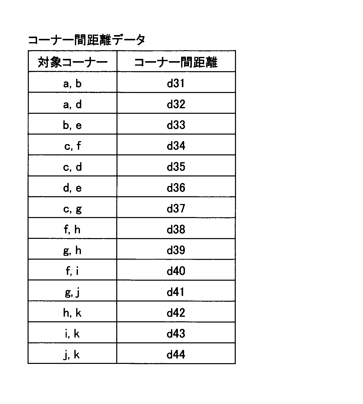
図12に示すように、ユーザーは、次に、プリンターの描画部品111の横にノートPCの描画部品112を手書きした。図12(b)のノートPCの描画部品112は、図9(b)に示したものと同様である。
As shown in FIG. 12, the user then hand-draws a notebook
ユーザーがノートPCの描画部品112を描くために最初のストローク107(点Oが始点で点Qが終点)を描くと、描画部品管理部24はストローク107の始点(点O)と先に描画されたプリンターの描画部品111が有するコーナーの中で点Oに最も近いコーナー(点f)との距離を求める。描画部品管理部24は、また、ストローク107の終点(点Q)とプリンターの描画部品111が有するコーナーの中で点Qに最も近いコーナー(点i)との距離を求める。そして、両方の距離が所定の値以上の場合は、描画部品管理部24は、プリンターの描画部品111とノートPCの描画部品112は別の図であると判断する。
When the user draws the first stroke 107 (starting at point O and ending at point Q) to draw the laptop
そして、描画部品管理部24は、プリンターの描画部品111のストロークデータ(接触位置検出部21から入力される座標点列、線の太さ、色等の描画属性データ)をファイルとして部品データ記憶部32に保存する。このファイル名は、例えば、「fig_parts_3.data」とする。描画部品管理部24は、また、このプリンターの描画部品111に対して描画部品ID=3を付与する。描画部品管理部24は、この描画部品ID、表7に示したコーナー座標データ、表8に示したコーナー間距離データ、及び、プリンターの描画部品111のストロークデータファイル名「fig_parts_3.data」を対応付けた描画部品管理テーブルを生成する。
Then, the drawing
描画部品管理部24は、描画部品管理テーブルのデータをファイルとして部品データ記憶部32に保存する。この描画部品管理ファイルのファイル名は、例えば、「fig_parts_table_2.data」とする(表9参照)。
The drawing
続いて、ユーザーがノートPCの描画部品112を手書きする。ユーザーが最後のストローク105(点Sが始点で点Tが終点)を描いてから、描画部品112のコーナーから所定の距離以上離れた位置に次のストロークを描画するか、又は、一定時間以内に次のストロークが手書きされない場合、描画図管理部23は、ストローク107からストローク105までを1つの描画部品と判断する。
Then, the user handwrites the
そして、描画部品管理部24はノートPCの描画部品112のストロークデータ(接触位置検出部21から入力される座標点列、線の太さ、色等の描画属性データ)をファイルとして部品データ記憶部32に保存する。このファイル名は、例えば、「fig_parts_4.data」とする。描画部品管理部24は、また、ノートPCの描画部品112に対して描画部品ID=4を付与する。描画部品管理部24は、描画部品ID、表3に示したコーナー座標データ、表4に示したコーナー間距離データ、及び、ノートPCの描画部品112のストロークデータファイル(「fig_parts_4.data」)を対応付けた描画部品管理テーブルを生成する(表9参照)。
Then, the drawing
描画部品管理部24は、この描画部品管理テーブルのデータを先に生成した描画部品管理ファイル(ファイル名は「fig_parts_table_2.data」)に追加して、部品データ記憶部32に上書き保存する。この描画部品管理テーブルを表9に示す。
The drawing

<全体図の保存>
図13に示すように、ユーザーがノートPCの描画部品112を手書きしてから所定の時間が経過した後に、ユーザーが電子黒板の描画部品111とノートPCの描画部品112とを結ぶ線108を手書きする。点mが始点で点nが終点を示している。その後、一定時間以内に次のストロークが手書きされない場合、この線108を1つの図と判断するが、描画図管理部23は、1つのストロークについてはファイルの保存処理は実行しない。
<Saving the whole map>
13, after a predetermined time has elapsed since the user hand-drawn the
そして、ユーザーが表示装置2のディスプレイ220に表示された全体図の保存ボタンを押下した。描画図管理部23は、図13に示した全てのストロークデータ(接触位置検出部21から入力される座標点列、線の太さ、色等の描画属性データ)をファイルとして全体図データ記憶部31に保存する。このファイル名は、例えば、「figure_2.data」とする。そして、描画図管理部23は、図13の全体図に対して描画図ID=1002を採番する。描画図管理部23は、描画図ID、描画部品管理ファイルのファイル名「fig_parts_table_2.data」、及び、全体図のストロークデータファイル名「figure_2.data」を対応付けて、既に存在する描画図管理テーブルに追加する。
Then, the user presses the save button for the overall drawing displayed on the
描画図管理部23は、描画図管理テーブルのデータを表6の描画図管理ファイル(ファイル名は「figure_table.data」)に上書き保存する。上書きされた描画図管理テーブルを表10に示す。
The

したがって、表10には、図10の全体図と全体図が有する2つの描画部品101,102が描画図ID=1001で対応付けられる。また、表10には、図13の全体図と全体図が有する2つの描画部品111,112が描画図ID=1002で対応付けられる。
10 and the two
なお、会議の終了時(ユーザーが会議の終了ボタンを押下した時)に、上記した全体図の保存処理を描画図管理部23が実行するようにしてもよい。
In addition, when the meeting ends (when the user presses the end meeting button), the
また、表示装置2がページ切り替え機能を持っている場合、ユーザーがページの切り替え操作を行った場合に、描画図管理部23が、上記した全体図の保存処理を実行するようにしてもよい。
In addition, if the
<描画部品の検索>
次に、ユーザーが表示装置2のディスプレイ220上で図を描き始めると、描画比較部25が、手書き中の描画部品と保存されている描画部品とを比較して類似性の判断を行い、類似した描画部品を有する全体図を表示する。以下、描画部品の検索と全体図の表示処理について説明する。
<Search for drawing parts>
Next, when the user starts drawing a diagram on the
ユーザーにより別の描画部品が手書きされると、上記と同様にして、描画部品管理部24が新たな描画部品IDを付与して(描画部品ID=5)、ストロークデータ、コーナー座標データ、及び、コーナー間距離データとの対応付けを行う。すなわち、描画部品管理部24は、表5及び表9に示した描画部品管理テーブルの1行分を作成する。
When the user handwrites another drawing part, the drawing
そして、描画部品管理部24は全体図データ記憶部31に保存されている描画図管理ファイル(ファイル名は「figure_table.data」)のデータをRAM203に読み出す。そして、描画部品管理部24は更に、描画図管理ファイルに含まれている描画部品管理ファイルのファイル名を使用して、部品データ記憶部32に保存されている全ての描画部品管理ファイルのデータ(描画部品管理テーブルのデータ)をRAM203に読み出す。
Then, the drawing
続いて、描画部品管理部24は、描画部品5(描画部品ID=5)のコーナー座標データとコーナー間距離データを、RAM203に読み出した描画部品管理テーブルのデータと比較する処理を描画比較部25に依頼する。
Next, the drawing
描画比較部25はコーナー座標データとコーナー間距離データを用いて、この描画部品5(描画部品ID=5)と部品データ記憶部32に記憶されていた描画部品との類似性を判断する。描画比較部25は、例えば、まず、コーナー間距離データの要素数が一致しているかどうかで比較対象を絞る。描画比較部25は、完全に一致するだけでなく、要素数が近いかどうかで絞ってもよい。
The
次に、描画比較部25は、コーナー間距離データに載っているコーナーのペアをベクトルの始点、終点とみなして、コーナー間距離データに記載の順に2つの描画部品それぞれのベクトルに対してコサイン類似度を計算する。
Next, the
コサイン類似度とは、2本のベクトルがどれくらい同じ向きを向いているのかを表す指標である。コサイン類似度は、そのまま、ベクトル同士の成す角度の近さを表現するため、三角関数のコサインの通り、1に近ければ類似しており、0に近ければ似ていないことになる。 Cosine similarity is an index that shows how similar two vectors are. Cosine similarity expresses the closeness of the angle between the vectors, so just like the cosine of the trigonometric function, the closer it is to 1, the more similar they are, and the closer it is to 0, the more dissimilar they are.
描画比較部25は、コーナー間距離データにある全てのベクトルについてコサイン類似度がしきい値(例えば0.7)以上であれば類似性があると判断する。なお、描画比較部25は、コーナー間距離データの全てのコーナーペア同士についてコサイン類似度の平均を求めてその値がしきい値(例えば0.7)以上であれば、類似性があると判断しても良い。
The
以下では、コサイン類似度に基づく類似性の判断例を説明する。 Below, we explain an example of determining similarity based on cosine similarity.
下記の表11、表12は、保存されている描画部品1(描画部品ID=1)のコーナー座標データとコーナー間距離データの各先頭部分のデータを示す(表1,2の先頭部分)。表13、表14は、現在、ユーザーが手書きした描画部品のコーナー座標データとコーナー間距離データの各先頭部分のデータである。 Tables 11 and 12 below show the data for the top portions of the corner coordinate data and corner distance data for the saved drawing component 1 (drawing component ID = 1) (top portions of Tables 1 and 2). Tables 13 and 14 show the data for the top portions of the corner coordinate data and corner distance data for the drawing components currently handwritten by the user.


描画比較部25は、表11~表14を使って、ユーザーが手書きした描画部品5(描画部品ID=5)と、描画部品1(描画部品ID=1)を比較する。なお、以下では、2つのコーナーを括弧[ ]で囲うことで、ベクトルを表す。
The
描画部品1が有する1つ目のコーナーペアのベクトルは[AB]=(x2-x1,y2-y1)、
2つ目のコーナーペアのベクトルは[AC]=(x3-x1,y3-y1)
描画部品5が有する1つ目のコーナーペアのベクトルは[αβ]=(x101-x100,y101-y100 )、
2つ目のコーナーペアのベクトルは[αγ]=(x102-x100,y102-y100 )である。
The vector of the first corner pair of drawing
The second corner pair vector is [AC] = (x3 - x1, y3 - y1).
The vector of the first corner pair of the
The vector of the second corner pair is [αγ]=(x102-x100,y102-y100).
1つ目のコーナーペア同士のコサイン類似度は式(1)で与えられる。同様に2つ目のコーナーペア同士のコサイン類似度は式(2)で与えられる。 The cosine similarity between the first corner pair is given by equation (1). Similarly, the cosine similarity between the second corner pair is given by equation (2).


このような描画部品5との比較を、描画比較部25が、描画部品(描画部品ID=1~4)と行う。描画部品5がノートPCの描画部品である場合、描画部品ID=2と4の描画部品と類似していると判断できる。
The
描画比較部25は類似性があると判断した描画部品ID=2と4を描画部品管理部24に通知する。描画部品管理部24は、この通知された描画部品IDを持つ描画部品管理ファイルのファイル名を描画図管理部23へ通知する。
The
描画図管理部23は描画図管理テーブルにあるこのファイル名に紐付いた全体図のストロークデータファイル(「figure_1.data」「figure_2.data」)を読み出して、描画データ生成部22が線の太さや色等の描画属性に従ったストロークの描画線を生成する。そして、描画データ生成部22は、この全体図を縮小してリストダイアログ130に入れ、表示制御部26がこのリストダイアログ130をディスプレイ220に表示する。
The
ユーザーがノートPCの描画部品を手書きした場合、図10及び図13の2つの全体図が検索に適合するため、表示制御部26は2つの全体図をリストダイアログ130に入れて表示する。この表示例を図14に示す。
When a user handwrites a drawing component on a notebook PC, the two overall views in FIG. 10 and FIG. 13 match the search, so the
図14(a)は、リストダイアログ130の表示例を示す。図14(a)では、現在、手書きされたノートPCの描画部品140とリストダイアログ130が表示されている。また、リストダイアログ130は、ノートPCの描画部品140と類似する描画部品を有する2つの全体図131,132を有している。
Figure 14 (a) shows an example of the display of the
ユーザーがリストダイアログ130に表示された電子黒板とノートPCの全体図131を選択すると、描画図管理部23はリストダイアログ130を消去して、電子黒板とノートPCの全体図131(描画図ID=1001)を表示する(図14(b))。
When the user selects the
<表示装置2の動作手順>
図15は、ユーザーが手書きした手書きデータに基づく描画部品と全体図の保存を説明するシーケンス図の一例である。
<Operation Procedure of
FIG. 15 is an example of a sequence diagram illustrating the saving of drawing components and an overall view based on handwritten data handwritten by a user.
S1:ユーザーが入力手段291の先端をディスプレイ220に接触した状態で移動させると、接触位置検出部21がストロークデータの入力を受け付ける。
S1: When the user moves the tip of the input means 291 while it is in contact with the
S2:接触位置検出部21は検出した座標点列を描画データ生成部22に通知する。
S2: The contact
S3:描画データ生成部22は座標点列を補間したりスムージングしたりして、手書きデータ(ストロークデータ)を生成する。描画データ生成部22は生成したストロークデータを表示制御部26に通知する。表示制御部26はストロークデータをディスプレイ220に表示する。
S3: The drawing
S4:また、描画データ生成部22はストロークデータを描画部品管理部24に通知する。
S4: The drawing
S5:描画部品管理部24は、コーナーの座標が登録されたコーナー座標データと、コーナー間距離データを生成する。
S5: The drawing
S6:描画部品管理部24は、手書きされた描画部品のコーナーから所定の距離以上離れた位置に次のストロークが手書きされたか、又は、最後のストロークが手書きされてから一定時間以内に次のストロークが手書きされない場合(所定の条件を満たす場合)、描画部品管理テーブルを生成する。描画部品管理部24は、所定の条件を最後に満たしてから次に満たすまでに、接触位置検出部21が受け付けたストロークデータを1つの描画部品と判断する。
S6: The drawing
描画部品管理テーブルには、描画部品ID、コーナー座標データ、コーナー間距離データ、及び、描画部品のストロークデータファイル名が対応付けられる。描画部品管理部24はこの描画部品管理テーブルをファイルとして部品データ記憶部32に保存する。
The drawing part management table associates the drawing part ID, corner coordinate data, corner distance data, and stroke data file name of the drawing part. The drawing
S7:ユーザーが表示装置2のディスプレイ220に表示された全体図の保存ボタンを押下した。
S7: The user presses the save button for the overall view displayed on the
S8:接触位置検出部21は、保存ボタンが押下された旨を描画図管理部23に通知する。
S8: The contact
S9:描画図管理部23は、ディスプレイ220の全てのストロークデータをファイルとして全体図データ記憶部31に保存する。描画図管理部23は、全体図に対して描画図IDを付与して、描画図ID、描画部品管理ファイルのファイル名、及び、全体図のストロークデータファイル名を対応付けて、描画図管理ファイルに保存する(既に描画図管理ファイルがある場合は上書きする)。
S9: The
図16は、ユーザーが手書きした描画部品と類似する描画部品を有する全体図を表示装置2が表示する手順を示すシーケンス図の一例である。
Figure 16 is an example of a sequence diagram showing the procedure by which the
S11~S16:S11~S16は、図15のステップS1~S6と同様でよい。 S11 to S16: S11 to S16 may be similar to steps S1 to S6 in Figure 15.
S17:描画部品管理部24は、ステップS16で保存した描画部品と、部品データ記憶部32に保存されている描画部品との比較を描画比較部25に要求する。描画比較部25は例えばコサイン類似度によりステップS16で保存した描画部品と類似する描画部品の描画部品IDを描画部品管理部24に返す。
S17: The drawing
S18:描画部品管理部24は、類似していると判断された描画部品IDの描画部品管理ファイルのファイル名を描画図管理部23に通知する。
S18: The drawing
S19,S20:描画図管理部23は、描画部品管理ファイルのファイル名を有する描画図管理ファイル(全体図)を全体図データ記憶部31から読み出す。
S19, S20: The drawing
S21:描画図管理部23は読み出した描画図管理ファイルを描画データ生成部22に通知する。
S21: The
S22:描画データ生成部22は描画図管理ファイルに含まれるストロークデータで全体図を生成し、全体図を含むリストダイアログ130の表示を表示制御部26に要求する。これにより、表示制御部26は全体図をサムネイル等の縮小された状態で含むリストダイアログ130をディスプレイ220に表示する。
S22: The drawing
S23:ユーザーが全体図を入力手段291で押下する。 S23: The user presses "Overall view" using the input means 291.
S24:接触位置検出部21は入力手段291の先端が接触する座標により、選択された全体図を特定する。接触位置検出部21はこの全体図を描画データ生成部22に通知する。
S24: The contact
S25:描画データ生成部22はこの全体図の表示を表示制御部26に要求する。これにより、表示制御部26は全体図をディスプレイ220に表示する。
S25: The drawing
図17は、図16の流れをフローチャートで示すフローチャート図の一例である。 Figure 17 is an example of a flowchart illustrating the flow of Figure 16.
描画部品管理部24は、手書きされた描画部品のコーナーから所定の距離以上離れた位置に次のストロークが手書きされたか、又は、最後のストロークが手書きされてから一定時間以内に次のストロークが手書きされない場合、ユーザーが描画部品を書き終えたと判断する(S101)。
The drawing
次に、描画比較部25は、ユーザーが書き終えた描画部品と、全体図データ記憶部31に保存されている全体図の描画部品とを比較する(S102)。
Next, the
全体図の描画部品にユーザーが書き終えた描画部品と類似している描画部品がある場合(S103のYes)、表示制御部26はリストダイアログ130をディスプレイ220に表示する(S104)。リストダイアログ130は、類似する描画部品を含む全体図をサムネイル等の縮小された状態で含む。
If there is a drawing component in the overall view that is similar to the drawing component that the user has finished drawing (Yes in S103), the
そして、ユーザーが全体図を入力手段291で押下した場合(S105のYes)、接触位置検出部21は入力手段291の先端が接触する座標により、選択された全体図を受け付け、表示制御部26が全体図をディスプレイ220に表示する(S106)。
When the user presses the overall view using the input means 291 (Yes in S105), the contact
<主な効果>
本実施形態の表示装置2は、全体図、及び、全体図が有する描画部品を保存しておく。その後、ユーザーが手書きで描画部品を手書きすると、その描画部品と保存している描画部品とを照合して、類似度が高いものがあれば、その描画部品を持つ全体図を表示する。したがって、ユーザーは全体図の一部を手書きすれば、過去に手書きした全体図を呼び出して再利用することができる。
<Major Effects>
The
実施例1では、ユーザーが手書きした図と、全ての保存されている全体図との類似性が比較された。しかし、保存されている全体図の量が多くなると比較する時間がかかるため検索対象をしぼることが好ましい。また、全体図の内容の機密性が高い場合、全体図を保存したユーザーがその全体図にアクセスできる人を制限したいことがある。 In the first embodiment, the similarity between the user's handwritten drawing and all stored overall drawings was compared. However, as the number of stored overall drawings increases, it takes time to make the comparison, so it is preferable to narrow down the search targets. Also, if the contents of the overall drawing are highly confidential, the user who saved the overall drawing may want to restrict who can access the overall drawing.
本実施例では、これを実現するためにユーザーIDを用いてそのユーザーが過去に作成した全体図のみを検索する表示装置2について説明する。
To achieve this, in this embodiment, we will explain a
<機能について>
図18は、本実施例の表示装置2が有する機能をブロック状に示す機能ブロック図の一例である。なお、図18の説明では、主に図4との相違を説明する。
<About the function>
Fig. 18 is an example of a functional block diagram showing functions of the
本実施例の表示装置2はログイン管理部29を有している。ログイン管理部29は、ICカード読取装置(図3では近距離通信部219が相当する)がNFCで受信した、ユーザーのICカードが保持するユーザーIDをもとにSSD204内に構成した認証データベースへ問い合わせて認証を行う。描画図管理部23と描画部品管理部24は認証されたユーザーIDに対応付けて描画部品と全体図を保存する。
The
なお、ログイン管理部29は、ICカードに書き込まれたユーザーIDをもとに認証するのでなく、ハードウェアキーボードや、タッチパネル上に表示したソフトウェアキーボードでユーザーが入力したユーザーIDとパスワードで認証してもよい。また、ログイン管理部29は生体認証してもよく、認証の形式は問わない。
The
また、ユーザーIDの問い合わせ先も表示装置2の内蔵のSSDではなく、表示装置2が別の認証サーバーに問い合わせてもよい。
In addition, the
<動作手順>
図19は、ユーザーが手書きした手書きデータに基づく描画部品と全体図の保存を説明するシーケンス図の一例である。なお、図19の説明では主に図15との相違を説明する。
<Operation procedure>
19 is an example of a sequence diagram for explaining the saving of drawing components and an overall view based on handwritten data handwritten by a user. Note that the explanation of FIG. 19 will mainly focus on the differences from FIG.
S31:ユーザーがICカードをICカードリーダーにかざす。 S31: The user holds the IC card over the IC card reader.
S32:ICカード読取装置(近距離通信部219)はICカードからユーザーIDを受信する。ログイン管理部29は近距離通信部219からユーザーIDを取得する。
S32: The IC card reader (short-distance communication unit 219) receives the user ID from the IC card. The
S33:ログイン管理部29はユーザーIDに基づいてユーザー認証を行う。
S33: The
S34:認証が成功した場合、ログイン管理部29はユーザーIDを描画部品管理部24に通知する。
S34: If authentication is successful, the
以降の処理は図15と同様になるが、ステップS40で、描画部品管理部24はユーザーIDに対応付けて、描画部品管理テーブルをファイルとして部品データ記憶部32に保存する。
The subsequent processing is the same as in FIG. 15, but in step S40, the drawing
ユーザーIDが0001で描画部品が2つの場合の例として表15に示す描画部品管理テーブルとなる。 As an example of a case where the user ID is 0001 and there are two drawing parts, the drawing part management table is shown in Table 15.

表5又は表9と比較すると、表15の描画部品管理テーブルには、ユーザーIDの項目が追加されている。描画比較部25は、現在、ログインしているユーザーのユーザーIDと同じユーザーIDに対応付けられている描画部品を検索対象にできる。
In comparison with Table 5 or Table 9, the drawing part management table of Table 15 has an additional item of "user ID." The
図20は、ユーザーが手書きした図と類似する描画部品を有する全体図を表示装置2が表示する手順を示すシーケンス図の一例である。図20の説明では主に図16との相違を説明する。
Figure 20 is an example of a sequence diagram showing the procedure by which the
S51~S54:ログイン手順は図19と同様でよい。 S51 to S54: The login procedure can be the same as in Figure 19.
S55~S60:ステップS55~S60は、図19のステップS35~S40と同様でよい。 S55 to S60: Steps S55 to S60 may be similar to steps S35 to S40 in FIG. 19.
S61:描画部品管理部24は、ログインしているユーザーのユーザーIDに対応付けられている描画部品のみを、ユーザーが手書きしている図と比較するように描画比較部25に要求する。
S61: The drawing
こうすることで、ログインしているユーザーのユーザーIDに対応付けられている描画部品のみと、ユーザーが手書きした描画部品とを描画比較部25が比較できる。表示装置2は、比較する時間を低減でき、全体図の内容の機密性が高い場合でも、全体図を閲覧できるユーザーを制限できる。
This allows the
以降の処理は図16と同様でよい。 The subsequent processing can be the same as in Figure 16.
<主な効果>
本実施例の表示装置2は、実施例1の効果に加え、表示装置2が描画部品を検索する時間を低減でき、全体図の内容の機密性が高い場合でも、全体図を閲覧できるユーザーを制限できる。
<Major Effects>
In addition to the effects of
なお、表示装置2は、ユーザーIDに基づいて描画部品を検索するのでなく、部署やチーム等、同じグループに所属するユーザーの描画部品を検索対象としてもよい。あるいは、描画部品にセキュリティレベルをユーザーが付与しておき、表示装置はセキュリティレベルが一定以下の描画部品を検索してもよい。
In addition, the
以下の実施例では表示装置2の別の構成例について説明する。
In the following example, another configuration example of the
<<表示装置の別の構成例1>>
本実施形態の表示装置2は大型のタッチパネルを有するものとして説明されているが、表示装置2はタッチパネルを有するものに限られない。
<<Another Configuration Example 1 of the Display Device>>
Although the
図21は、表示装置2の他の構成例を示す図である。図21では、スクリーン413の上辺にプロジェクター411が設置されている。このプロジェクター411が表示装置2に相当する。なお、スクリーンは黒板でもよく、映像を投影するだけの広さの平面であればよい。
Fig. 21 is a diagram showing another example of the configuration of the
プロジェクター411は超短焦点の光学系を有しており、10cm程度から歪みの少ない映像をスクリーン413に投影できる。この映像は、無線又は有線で接続されたPCから送信されてもよいし、プロジェクター411が記憶していてもよい。
The
ユーザーは専用の電子ペン2501を使ってスクリーン413に手書きする。電子ペン2501は、ユーザーが手書きのためにスクリーン413に押しつけるとスイッチがONになり発光する発光部を例えば先端部に有している。光の波長は近赤外や赤外なのでユーザーの目には見えない。プロジェクター411はカメラを有しており、発光部を撮像して画像を解析し電子ペン2501の方向を特定する。また、電子ペン2501は発光と共に音波を発信しており、プロジェクター411は音波の到達時間により距離を算出する。プロジェクター411は、方向と距離により電子ペン2501の位置を特定できる。電子ペン2501の位置には手書きされたデータが描画(投影)される。
The user writes by hand on the
プロジェクター411はメニュー430を投影するので、ユーザーが電子ペン2501でボタンを押下すると、プロジェクター411が電子ペン2501の位置とスイッチのON信号により押下されたボタンを特定する。例えば、保存ボタン431が押下されると、ユーザーが手書きしたデータ(座標点列)がプロジェクター411で保存される。プロジェクター411は、予め定められたサーバー412又はUSBメモリ2600等に手書き情報を保存する。
The
<<表示装置の別の構成例2>>
図22は、表示装置2の他の構成例を示す図である。図22の例では、表示装置2が、端末装置600、画像投影装置700A、及び、ペン動作検出装置810を有する。
<<Another Configuration Example 2 of the Display Device>>
22 is a diagram showing another example of the configuration of the
端末装置600は、画像投影装置700A及びペン動作検出装置810と有線で接続されている。画像投影装置700Aは、端末装置600により入力された画像データをスクリーン800に投影させる。
The
ペン動作検出装置810は、電子ペン820と通信を行っており、スクリーン800の近傍における電子ペン820の動作を検出する。具体的には、ペン動作検出装置810は、スクリーン800上において、電子ペン820が示している点を示す座標情報を検出し(検出方法は図21と同様でよい)、端末装置600へ送信する。
The pen
端末装置600は、ペン動作検出装置810から受信した座標情報に基づき、電子ペン820によって入力される手書きデータの画像データを生成し、画像投影装置700Aによって手書きデータの画像をスクリーン800に描画させる。
Based on the coordinate information received from the pen
また、端末装置600は、画像投影装置700Aに投影させている背景画像と、電子ペン820によって入力された手書データの画像とを合成した重畳画像を示す重畳画像データを生成する。
In addition, the
<<表示装置の別の構成例3>>
図23は、表示装置2の構成例を示す図である。図23の例では、表示装置2が、端末装置600と、ディスプレイ800Aと、ペン動作検出装置810Aとを有する。
<<Another Configuration Example 3 of the Display Device>>
Fig. 23 is a diagram showing an example of the configuration of the
ペン動作検出装置810Aは、ディスプレイ800Aの近傍に配置され、ディスプレイ800A上に、電子ペン820Aが示している点を示す座標情報を検出し(検出方法は図21と同様でよい)、端末装置600へ送信する。なお、図23の例では、電子ペン820Aは、端末装置600によってUSBコネクタを介して充電されても良い。
The pen
端末装置600は、ペン動作検出装置810Aから受信した座標情報に基づき、電子ペン820Aによって入力される手書データの画像データを生成し、ディスプレイ800Aに表示させる。
Based on the coordinate information received from the pen
<<表示装置の別の構成例4>>
図24は、表示装置2の構成例を示す図である。図24の例では、表示装置2が、端末装置600と、画像投影装置700Aとを有する。
<<Another Configuration Example 4 of the Display Device>>
Fig. 24 is a diagram showing a configuration example of the
端末装置600は、電子ペン820Bと無線通信(Bluetooth(登録商標)等)を行って、スクリーン800上において電子ペン820Bが示す点の座標情報を受信する。座標情報は、スクリーン800に形成された微小な位置情報を電子ペン820Bが読み取ってもよいし、スクリーン800から座標情報を受信してもよい。
The
そして、端末装置600は、受信した座標情報に基づき、電子ペン820Bにより入力される手書データの画像データを生成し、画像投影装置700Aに手書データの画像を投影させる。
Then, based on the received coordinate information, the
また、端末装置600は、画像投影装置700Aに投影させている背景画像と、電子ペン820Bによって入力された手書データの画像とを合成した重畳画像を示す重畳画像データを生成する。
In addition, the
以上のように、上記した各実施形態は、様々なシステム構成において適用することができる。 As described above, each of the above-mentioned embodiments can be applied to various system configurations.
<その他の適用例>
以上、本発明を実施するための最良の形態について実施例を用いて説明したが、本発明はこうした実施例に何等限定されるものではなく、本発明の要旨を逸脱しない範囲内において種々の変形及び置換を加えることができる。
<Other application examples>
The above describes the best mode for carrying out the present invention using examples, but the present invention is not limited to these examples in any way, and various modifications and substitutions can be made within the scope that does not deviate from the gist of the present invention.
例えば、本実施形態では、描画比較部25がコサイン類似度で描画部品のコーナーのペアのベクトルに対して類似度を評価したが、類似度は描画部品の画像データのパターンマッチングなどで求めてもよい。
For example, in this embodiment, the
また、本実施形態では、電子黒板として使用できる表示装置を説明したが、表示装置は画像を表示できればよく、例えばデジタルサイネージなどでもよい。また、ディスプレイでなくプロジェクターの表示データを表示してもよい。この場合、本実施形態ではペン先の座標をタッチパネルで検知する方法でペンの座標を検出したが、表示装置2は、ペン先の座標を超音波により検出してもよい。ペンは発光と共に超音波を発信しており、表示装置2は超音波の到達時間により距離を算出する。表示装置2は、方向と距離によりペンの位置を特定できる。ペンの軌跡をストロークとしてプロジェクターが描画(投影)する。
In addition, in this embodiment, a display device that can be used as an electronic whiteboard has been described, but the display device may be any device capable of displaying images, such as digital signage. Also, instead of a display, display data from a projector may be displayed. In this case, in this embodiment, the coordinates of the pen are detected by a method in which the coordinates of the pen tip are detected by a touch panel, but the
また、本実施形態では電子黒板を一例として説明したが、タッチパネルを有する情報処理装置であれば好適に適用できる。電子黒板と同様の機能を有する装置を、電子ホワイトボード、電子情報ボード、インタラクティブボードなどともいう。タッチパネルを搭載した情報処理装置としては、例えば、PJ(Projector:プロジェクター)、デジタルサイネージ等の出力装置、HUD(Head Up Display)装置、産業機械、撮像装置、集音装置、医療機器、ネットワーク家電、ノートPC(Personal Computer)、携帯電話、スマートフォン、タブレット端末、ゲーム機、PDA、デジタルカメラ、ウェアラブルPC又はデスクトップPC等であってもよい。 In addition, although an electronic whiteboard has been described as an example in this embodiment, any information processing device having a touch panel can be suitably applied. A device having the same function as an electronic whiteboard is also called an electronic whiteboard, an electronic information board, an interactive board, etc. Examples of information processing devices equipped with a touch panel include output devices such as PJ (Projector), digital signage, HUD (Head Up Display) devices, industrial machinery, imaging devices, sound collection devices, medical equipment, network home appliances, notebook PCs (Personal Computers), mobile phones, smartphones, tablet terminals, game consoles, PDAs, digital cameras, wearable PCs, or desktop PCs.
また、図4などの構成例は、表示装置2による処理の理解を容易にするために、主な機能に応じて分割したものである。処理単位の分割の仕方や名称によって本願発明が制限されることはない。表示装置2の処理は、処理内容に応じて更に多くの処理単位に分割することもできる。また、1つの処理単位が更に多くの処理を含むように分割することもできる。
The configuration examples in FIG. 4 and the like are divided according to the main functions to make it easier to understand the processing by the
また、表示装置2が単体で本実施形態の機能を有する場合を説明したが、表示装置2の機能をサーバーが提供してもよい。この場合、表示装置2とサーバーがネットワークを介して通信する。表示装置2は手書きデータを表示すると共にサーバーに送信し、サーバーが文字認識や表機能などを提供する。
Although the
また、本実施形態において、比較の対象としてしきい値が例示されていたとしても、しきい値は例示された値には限定されない。このため、本実施形態では、全てのしきい値に関し、しきい値未満としきい値以下という記載は同等の意味を持ち、しきい値超過としきい値以上という記載は同等の意味を持つ。例えば、しきい値を11とした場合のしきい値未満という記載はしきい値が10である場合のしきい値以下と同等の意味を持つ。また、しきい値を10とした場合のしきい値超過という記載はしきい値が11である場合のしきい値以上と同等の意味を持つ。 In addition, in this embodiment, even if a threshold value is exemplified as an object of comparison, the threshold value is not limited to the exemplified value. For this reason, in this embodiment, for all threshold values, the descriptions "less than threshold value" and "below threshold value" have the same meaning, and the descriptions "exceeding threshold value" and "above threshold value" have the same meaning. For example, the description "less than threshold value" when the threshold value is 11 has the same meaning as the description "below threshold value" when the threshold value is 10. Furthermore, the description "exceeding threshold value" when the threshold value is 10 has the same meaning as the description "above threshold value" when the threshold value is 11.
また、上記で説明した実施形態の各機能は、一又は複数の処理回路によって実現することが可能である。ここで、本明細書における「処理回路」とは、電子回路により実装されるプロセッサのようにソフトウェアによって各機能を実行するようプログラミングされたプロセッサや、上記で説明した各機能を実行するよう設計されたASIC(Application Specific Integrated Circuit)、DSP(digital signal processor)、FPGA(field programmable gate array)や従来の回路モジュール等のデバイスを含むものとする。 Furthermore, each function of the embodiments described above can be realized by one or more processing circuits. Here, the term "processing circuit" in this specification includes a processor programmed to execute each function by software, such as a processor implemented by an electronic circuit, and devices such as an ASIC (Application Specific Integrated Circuit), DSP (digital signal processor), FPGA (field programmable gate array), and conventional circuit modules designed to execute each function described above.
なお、接触位置検出部21は受付手段の一例である。ログイン管理部29は認証手段の一例である。描画部品管理部24は保存手段の一例である。表示制御部26は表示制御手段の一例である。描画比較部25は類似度算出手段の一例である。
The contact
2 表示装置 2 Display device
Claims (8)
所定の条件で区分された複数の前記ストロークデータを描画部品として保存し、1つ以上の前記描画部品を含む描画データを保存する保存手段と、
前記受付手段が前記描画部品の入力を受け付けた場合、入力された前記描画部品と、前記保存手段が保存した前記描画部品とに基づいて、保存されている前記描画部品を含む前記描画データを表示する表示制御手段と、を有し、
前記保存手段は、前記描画部品が有する2つのストロークデータの間の距離が所定の値以下で、かつ、前記2つのストロークデータの方向が成す角度がしきい値以上又はしきい値超過である場合、前記2つのストロークデータの間の距離が最小となる線分の中点をコーナーとして検出し、または、ストロークデータの方向が変化した点の前後のストロークデータの方向が成す角度がしきい値以上又はしきい値超過である場合に前記変化した点をコーナーとして検出し、前記描画データに対応づけて前記描画部品の前記コーナーの座標を保存しておき、
前記コーナーの座標に基づいて、前記受付手段が入力を受け付けた前記描画部品と、前記保存手段が保存した前記描画部品との類似度を算出する類似度算出手段を有する、
ことを特徴とする表示装置。 A receiving means for receiving input of stroke data;
a storage means for storing a plurality of the stroke data classified according to a predetermined condition as drawing components and for storing drawing data including one or more of the drawing components;
a display control means for displaying the drawing data including the stored drawing component based on the input drawing component and the drawing component stored by the storage means when the receiving means receives an input of the drawing component ,
said storage means detects, as a corner, a midpoint of a line segment at which the distance between the two stroke data of said drawing component is the smallest when the distance between the two stroke data is equal to or smaller than a predetermined value and the angle formed by the directions of the two stroke data is equal to or larger than a threshold value, or detects, as a corner, a point at which the direction of stroke data changes when an angle formed by the directions of stroke data before and after the point is equal to or larger than a threshold value, and stores coordinates of the corner of said drawing component in association with said drawing data;
a similarity calculation means for calculating a similarity between the drawing component inputted by the receiving means and the drawing component stored by the storing means based on the coordinates of the corners ;
A display device comprising:
前記描画データのリストにおいて選択を受け付けた前記描画データを表示することを特徴とする請求項1又は2に記載の表示装置。 the display control means displays a list of the drawing data including the drawing components stored based on the drawing components input by the receiving means and the drawing components stored by the storage means;
3. The display device according to claim 1, wherein the drawing data selected in the list of drawing data is displayed.
前記受付手段が最後にストロークデータを受け付けてから一定時間以内に次のストロークデータを受け付けない場合、であり、
前記保存手段は、前記所定の条件を最後に満たしてから次に満たすまでに、前記受付手段が受け付けたストロークデータを1つの前記描画部品と判断する請求項1~3のいずれか1項に記載の表示装置。 The predetermined condition is whether the input of the next stroke data is received at a position that is a predetermined distance or more away from the last stroke data received by the receiving means, or
When the reception means does not receive the next stroke data within a certain period of time after the last stroke data is received,
The display device according to any one of claims 1 to 3, wherein the storage means determines that stroke data accepted by the acceptance means from the last time the specified condition is satisfied until the next time the specified condition is satisfied as one drawing component.
前記コサイン類似度としきい値を比較することで、前記受付手段が入力を受け付けた前記描画部品と、前記保存手段が保存した前記描画部品が類似しているか否かを判断することを特徴とする請求項1に記載の表示装置。 the similarity calculation means calculates a cosine similarity between coordinates of the adjacent corners of the drawing component whose input has been accepted by the accepting means and coordinates of the adjacent corners of the drawing component whose input has been stored by the storing means;
The display device according to claim 1, characterized in that the cosine similarity is compared with a threshold value to determine whether the drawing component whose input has been accepted by the accepting means is similar to the drawing component stored by the storing means .
前記保存手段は前記ユーザーに対応付けて前記描画部品及び前記描画データを保存しておき、
前記受付手段が前記ユーザーにより前記描画部品の入力を受け付けた場合、入力された前記描画部品と、前記保存手段が前記ユーザーに対応付けて保存した前記描画部品とに基づいて、保存されている前記描画部品を含む前記描画データを表示する請求項1~5のいずれか1項に記載の表示装置。 having an authentication means for authenticating a user;
the storage means stores the drawing components and the drawing data in association with the user;
A display device according to any one of claims 1 to 5, wherein when the receiving means receives input of the drawing part by the user, the display device displays the drawing data including the stored drawing part based on the input drawing part and the drawing part stored by the storage means in association with the user.
保存手段が、所定の条件で区分された複数の前記ストロークデータを描画部品として保存し、1つ以上の前記描画部品を含む描画データを保存するステップと、
前記受付手段が前記描画部品の入力を受け付けた場合、入力された前記描画部品と、前記保存手段が保存した前記描画部品とに基づいて、表示制御手段が、保存されている前記描画部品を含む前記描画データを表示するステップと、
前記保存手段が、前記描画部品が有する2つのストロークデータの間の距離が所定の値以下で、かつ、前記2つのストロークデータの方向が成す角度がしきい値以上又はしきい値超過である場合、前記2つのストロークデータの間の距離が最小となる線分の中点をコーナーとして検出し、または、ストロークデータの方向が変化した点の前後のストロークデータの方向が成す角度がしきい値以上又はしきい値超過である場合に前記変化した点をコーナーとして検出し、前記描画データに対応づけて前記描画部品の前記コーナーの座標を保存しておくステップと、
類似度算出手段が、前記コーナーの座標に基づいて、前記受付手段が入力を受け付けた前記描画部品と、前記保存手段が保存した前記描画部品との類似度を算出するステップと、
を有する表示方法。 A step of receiving an input of stroke data by a receiving means;
a step of storing the plurality of stroke data classified according to a predetermined condition as drawing parts, and storing drawing data including one or more of the drawing parts;
a step of, when the receiving means receives an input of the drawing component, a display control means displays the drawing data including the stored drawing component based on the input drawing component and the drawing component stored by the storage means;
said storage means detects, when a distance between two stroke data of said drawing component is equal to or smaller than a predetermined value and an angle formed by the directions of said two stroke data is equal to or larger than a threshold value, a midpoint of a line segment at which the distance between said two stroke data is the smallest as a corner, or detects, when an angle formed by directions of stroke data before and after a point at which a direction of stroke data changes is equal to or larger than a threshold value, said point at which the direction of stroke data changes as a corner, and stores coordinates of said corner of said drawing component in association with said drawing data;
a similarity calculation means for calculating a similarity between the drawing component whose input is accepted by the accepting means and the drawing component stored by the storing means, based on the coordinates of the corner;
A display method having the following structure:
ストロークデータの入力を受け付ける受付手段と、
所定の条件で区分された複数の前記ストロークデータを描画部品として保存し、1つ以上の前記描画部品を含む描画データを保存する保存手段と、
前記受付手段が前記描画部品の入力を受け付けた場合、入力された前記描画部品と、前記保存手段が保存した前記描画部品とに基づいて、保存されている前記描画部品を含む前記描画データを表示する表示制御手段、として機能させ、
前記保存手段は、前記描画部品が有する2つのストロークデータの間の距離が所定の値以下で、かつ、前記2つのストロークデータの方向が成す角度がしきい値以上又はしきい値超過である場合、前記2つのストロークデータの間の距離が最小となる線分の中点をコーナーとして検出し、または、ストロークデータの方向が変化した点の前後のストロークデータの方向が成す角度がしきい値以上又はしきい値超過である場合に前記変化した点をコーナーとして検出し、前記描画データに対応づけて前記描画部品の前記コーナーの座標を保存しておき、
前記コーナーの座標に基づいて、前記受付手段が入力を受け付けた前記描画部品と、前記保存手段が保存した前記描画部品との類似度を算出する類似度算出手段、
として機能させるためのプログラム。 The display device,
A receiving means for receiving input of stroke data;
a storage means for storing a plurality of the stroke data classified according to a predetermined condition as drawing components and for storing drawing data including one or more of the drawing components;
when the receiving means receives an input of the drawing component, the display control means functions as a display control means for displaying the drawing data including the stored drawing component based on the input drawing component and the drawing component stored by the storage means;
said storage means detects, as a corner, a midpoint of a line segment at which the distance between the two stroke data of said drawing component is the smallest when the distance between the two stroke data is equal to or smaller than a predetermined value and the angle formed by the directions of the two stroke data is equal to or larger than a threshold value, or detects, as a corner, a point at which the direction of stroke data changes when an angle formed by the directions of stroke data before and after the point is equal to or larger than a threshold value, and stores coordinates of the corner of said drawing component in association with said drawing data;
a similarity calculation means for calculating a similarity between the drawing component inputted by the receiving means and the drawing component stored by the storage means based on the coordinates of the corner ;
A program to function as a
Priority Applications (3)
| Application Number | Priority Date | Filing Date | Title |
|---|---|---|---|
| JP2021049023A JP7613193B2 (en) | 2021-03-23 | 2021-03-23 | Display device, display method, and program |
| US17/695,832 US11734940B2 (en) | 2021-03-23 | 2022-03-16 | Display apparatus, display method, and non-transitory recording medium |
| JP2024229705A JP2025036609A (en) | 2021-03-23 | 2024-12-26 | Display device, display method, and program |
Applications Claiming Priority (1)
| Application Number | Priority Date | Filing Date | Title |
|---|---|---|---|
| JP2021049023A JP7613193B2 (en) | 2021-03-23 | 2021-03-23 | Display device, display method, and program |
Related Child Applications (1)
| Application Number | Title | Priority Date | Filing Date |
|---|---|---|---|
| JP2024229705A Division JP2025036609A (en) | 2021-03-23 | 2024-12-26 | Display device, display method, and program |
Publications (2)
| Publication Number | Publication Date |
|---|---|
| JP2022147675A JP2022147675A (en) | 2022-10-06 |
| JP7613193B2 true JP7613193B2 (en) | 2025-01-15 |
Family
ID=83364854
Family Applications (2)
| Application Number | Title | Priority Date | Filing Date |
|---|---|---|---|
| JP2021049023A Active JP7613193B2 (en) | 2021-03-23 | 2021-03-23 | Display device, display method, and program |
| JP2024229705A Pending JP2025036609A (en) | 2021-03-23 | 2024-12-26 | Display device, display method, and program |
Family Applications After (1)
| Application Number | Title | Priority Date | Filing Date |
|---|---|---|---|
| JP2024229705A Pending JP2025036609A (en) | 2021-03-23 | 2024-12-26 | Display device, display method, and program |
Country Status (2)
| Country | Link |
|---|---|
| US (1) | US11734940B2 (en) |
| JP (2) | JP7613193B2 (en) |
Citations (7)
| Publication number | Priority date | Publication date | Assignee | Title |
|---|---|---|---|---|
| JP2001126081A (en) | 1999-09-09 | 2001-05-11 | Sony United Kingdom Ltd | Device and method for identifying picture |
| JP2007265171A (en) | 2006-03-29 | 2007-10-11 | Toshiba Corp | Input device and method thereof |
| US20090138830A1 (en) | 2005-06-20 | 2009-05-28 | Shekhar Ramachandra Borgaonkar | Method, article, apparatus and computer system for inputting a graphical object |
| JP2014038384A (en) | 2012-08-10 | 2014-02-27 | Toshiba Corp | Handwritten document processing apparatus, method and program |
| WO2014147722A1 (en) | 2013-03-18 | 2014-09-25 | 株式会社 東芝 | Electronic apparatus, method, and program |
| JP2015072534A (en) | 2013-10-02 | 2015-04-16 | ソニー株式会社 | Information processing apparatus, information processing method, and program |
| JP2016027493A (en) | 2015-09-29 | 2016-02-18 | 株式会社東芝 | Document classification support device, document classification support method, and document classification support program |
Family Cites Families (6)
| Publication number | Priority date | Publication date | Assignee | Title |
|---|---|---|---|---|
| JP2000165577A (en) | 1998-11-30 | 2000-06-16 | Ricoh Co Ltd | Meeting support device |
| JP6270565B2 (en) * | 2014-03-18 | 2018-01-31 | 株式会社東芝 | Electronic apparatus and method |
| JP6668598B2 (en) | 2014-05-19 | 2020-03-18 | 株式会社リコー | System and communication method |
| JP7205386B2 (en) | 2019-05-31 | 2023-01-17 | 株式会社リコー | IMAGING DEVICE, IMAGE PROCESSING METHOD, AND PROGRAM |
| JP7310546B2 (en) | 2019-10-30 | 2023-07-19 | 株式会社リコー | Display device, display method, program, image processing system |
| JP2022019426A (en) | 2020-07-17 | 2022-01-27 | 株式会社リコー | Display device, control method, program |
-
2021
- 2021-03-23 JP JP2021049023A patent/JP7613193B2/en active Active
-
2022
- 2022-03-16 US US17/695,832 patent/US11734940B2/en active Active
-
2024
- 2024-12-26 JP JP2024229705A patent/JP2025036609A/en active Pending
Patent Citations (7)
| Publication number | Priority date | Publication date | Assignee | Title |
|---|---|---|---|---|
| JP2001126081A (en) | 1999-09-09 | 2001-05-11 | Sony United Kingdom Ltd | Device and method for identifying picture |
| US20090138830A1 (en) | 2005-06-20 | 2009-05-28 | Shekhar Ramachandra Borgaonkar | Method, article, apparatus and computer system for inputting a graphical object |
| JP2007265171A (en) | 2006-03-29 | 2007-10-11 | Toshiba Corp | Input device and method thereof |
| JP2014038384A (en) | 2012-08-10 | 2014-02-27 | Toshiba Corp | Handwritten document processing apparatus, method and program |
| WO2014147722A1 (en) | 2013-03-18 | 2014-09-25 | 株式会社 東芝 | Electronic apparatus, method, and program |
| JP2015072534A (en) | 2013-10-02 | 2015-04-16 | ソニー株式会社 | Information processing apparatus, information processing method, and program |
| JP2016027493A (en) | 2015-09-29 | 2016-02-18 | 株式会社東芝 | Document classification support device, document classification support method, and document classification support program |
Also Published As
| Publication number | Publication date |
|---|---|
| US20220309818A1 (en) | 2022-09-29 |
| JP2025036609A (en) | 2025-03-14 |
| JP2022147675A (en) | 2022-10-06 |
| US11734940B2 (en) | 2023-08-22 |
Similar Documents
| Publication | Publication Date | Title |
|---|---|---|
| JP7613526B2 (en) | Handwriting input device, handwriting input method, program, and input system | |
| JP7559496B2 (en) | Input device, input method, and program | |
| JP7600781B2 (en) | Display device, display method, and program | |
| JP7613060B2 (en) | Display device, display method, and program | |
| JP7452155B2 (en) | Handwriting input device, handwriting input method, program | |
| JP7615805B2 (en) | Display device, program, display method, and display system | |
| Liang et al. | Turn any display into a touch screen using infrared optical technique | |
| JP2025159004A (en) | Display device, display method, and program | |
| JP7786523B2 (en) | Input device, input method, and program | |
| JP7694010B2 (en) | Display device, color-compatible device, display method, and program | |
| JP7613193B2 (en) | Display device, display method, and program | |
| US20230315283A1 (en) | Display apparatus, display method, display system, and recording medium | |
| JP7543788B2 (en) | Display device, input method, and program | |
| JP7683253B2 (en) | Display device, program, conversion method, and display system | |
| JP7608874B2 (en) | Display device, display method, and program | |
| JP7739733B2 (en) | Display device, display method, program, and display system | |
| JP7615810B2 (en) | Display device, display method, and program | |
| JP7480608B2 (en) | Display device, display method, and program | |
| JP2022143788A (en) | Display device, method for display, and program | |
| JP7604974B2 (en) | Display device, display method, and program | |
| JP7619115B2 (en) | Display device, display method, and program | |
| JP7508916B2 (en) | Display device, display method, and program | |
| JP2023137822A (en) | Display device, fair copy method, program, and information sharing system | |
| JP2024135959A (en) | Display device, display system, server device, display method, and program | |
| JP2021096844A (en) | Display unit, display method, and program |
Legal Events
| Date | Code | Title | Description |
|---|---|---|---|
| A621 | Written request for application examination |
Free format text: JAPANESE INTERMEDIATE CODE: A621 Effective date: 20240119 |
|
| A977 | Report on retrieval |
Free format text: JAPANESE INTERMEDIATE CODE: A971007 Effective date: 20240830 |
|
| A131 | Notification of reasons for refusal |
Free format text: JAPANESE INTERMEDIATE CODE: A131 Effective date: 20240917 |
|
| A521 | Request for written amendment filed |
Free format text: JAPANESE INTERMEDIATE CODE: A523 Effective date: 20241111 |
|
| TRDD | Decision of grant or rejection written | ||
| A01 | Written decision to grant a patent or to grant a registration (utility model) |
Free format text: JAPANESE INTERMEDIATE CODE: A01 Effective date: 20241126 |
|
| A61 | First payment of annual fees (during grant procedure) |
Free format text: JAPANESE INTERMEDIATE CODE: A61 Effective date: 20241209 |
|
| R150 | Certificate of patent or registration of utility model |
Ref document number: 7613193 Country of ref document: JP Free format text: JAPANESE INTERMEDIATE CODE: R150 |