JP7614937B2 - ピンホール検出装置 - Google Patents
ピンホール検出装置 Download PDFInfo
- Publication number
- JP7614937B2 JP7614937B2 JP2021079607A JP2021079607A JP7614937B2 JP 7614937 B2 JP7614937 B2 JP 7614937B2 JP 2021079607 A JP2021079607 A JP 2021079607A JP 2021079607 A JP2021079607 A JP 2021079607A JP 7614937 B2 JP7614937 B2 JP 7614937B2
- Authority
- JP
- Japan
- Prior art keywords
- light source
- light
- inspected
- optical
- pinhole
- Prior art date
- Legal status (The legal status is an assumption and is not a legal conclusion. Google has not performed a legal analysis and makes no representation as to the accuracy of the status listed.)
- Active
Links
- 238000001514 detection method Methods 0.000 title claims description 37
- 230000003287 optical effect Effects 0.000 claims description 82
- 239000013307 optical fiber Substances 0.000 claims description 49
- 230000010287 polarization Effects 0.000 claims description 17
- 230000000644 propagated effect Effects 0.000 claims description 4
- 238000003892 spreading Methods 0.000 claims description 2
- 230000032258 transport Effects 0.000 description 17
- 239000000835 fiber Substances 0.000 description 7
- 238000007689 inspection Methods 0.000 description 7
- 239000000463 material Substances 0.000 description 6
- 230000005540 biological transmission Effects 0.000 description 5
- 229910000831 Steel Inorganic materials 0.000 description 4
- 239000010959 steel Substances 0.000 description 4
- 230000007547 defect Effects 0.000 description 3
- 238000004519 manufacturing process Methods 0.000 description 3
- 238000000034 method Methods 0.000 description 3
- 230000005856 abnormality Effects 0.000 description 2
- 238000006243 chemical reaction Methods 0.000 description 2
- 238000010586 diagram Methods 0.000 description 2
- 238000005259 measurement Methods 0.000 description 2
- 238000005253 cladding Methods 0.000 description 1
- 230000000694 effects Effects 0.000 description 1
- 239000000203 mixture Substances 0.000 description 1
- 238000012986 modification Methods 0.000 description 1
- 230000004048 modification Effects 0.000 description 1
- 230000001902 propagating effect Effects 0.000 description 1
Images
Classifications
-
- G—PHYSICS
- G01—MEASURING; TESTING
- G01N—INVESTIGATING OR ANALYSING MATERIALS BY DETERMINING THEIR CHEMICAL OR PHYSICAL PROPERTIES
- G01N21/00—Investigating or analysing materials by the use of optical means, i.e. using sub-millimetre waves, infrared, visible or ultraviolet light
- G01N21/84—Systems specially adapted for particular applications
- G01N21/86—Investigating moving sheets
-
- G—PHYSICS
- G01—MEASURING; TESTING
- G01N—INVESTIGATING OR ANALYSING MATERIALS BY DETERMINING THEIR CHEMICAL OR PHYSICAL PROPERTIES
- G01N21/00—Investigating or analysing materials by the use of optical means, i.e. using sub-millimetre waves, infrared, visible or ultraviolet light
- G01N21/84—Systems specially adapted for particular applications
- G01N21/88—Investigating the presence of flaws or contamination
- G01N21/89—Investigating the presence of flaws or contamination in moving material, e.g. running paper or textiles
- G01N21/892—Investigating the presence of flaws or contamination in moving material, e.g. running paper or textiles characterised by the flaw, defect or object feature examined
- G01N21/894—Pinholes
-
- G—PHYSICS
- G01—MEASURING; TESTING
- G01N—INVESTIGATING OR ANALYSING MATERIALS BY DETERMINING THEIR CHEMICAL OR PHYSICAL PROPERTIES
- G01N21/00—Investigating or analysing materials by the use of optical means, i.e. using sub-millimetre waves, infrared, visible or ultraviolet light
- G01N21/84—Systems specially adapted for particular applications
- G01N21/88—Investigating the presence of flaws or contamination
- G01N21/8806—Specially adapted optical and illumination features
-
- G—PHYSICS
- G01—MEASURING; TESTING
- G01N—INVESTIGATING OR ANALYSING MATERIALS BY DETERMINING THEIR CHEMICAL OR PHYSICAL PROPERTIES
- G01N21/00—Investigating or analysing materials by the use of optical means, i.e. using sub-millimetre waves, infrared, visible or ultraviolet light
- G01N21/84—Systems specially adapted for particular applications
- G01N21/88—Investigating the presence of flaws or contamination
- G01N21/89—Investigating the presence of flaws or contamination in moving material, e.g. running paper or textiles
- G01N21/8901—Optical details; Scanning details
- G01N21/8903—Optical details; Scanning details using a multiple detector array
-
- G—PHYSICS
- G01—MEASURING; TESTING
- G01N—INVESTIGATING OR ANALYSING MATERIALS BY DETERMINING THEIR CHEMICAL OR PHYSICAL PROPERTIES
- G01N21/00—Investigating or analysing materials by the use of optical means, i.e. using sub-millimetre waves, infrared, visible or ultraviolet light
- G01N21/84—Systems specially adapted for particular applications
- G01N21/86—Investigating moving sheets
- G01N2021/8609—Optical head specially adapted
- G01N2021/8627—Optical head specially adapted with an illuminator over the whole width
- G01N2021/8636—Detecting arrangement therefore, e.g. collimators, screens
-
- G—PHYSICS
- G01—MEASURING; TESTING
- G01N—INVESTIGATING OR ANALYSING MATERIALS BY DETERMINING THEIR CHEMICAL OR PHYSICAL PROPERTIES
- G01N21/00—Investigating or analysing materials by the use of optical means, i.e. using sub-millimetre waves, infrared, visible or ultraviolet light
- G01N21/84—Systems specially adapted for particular applications
- G01N21/86—Investigating moving sheets
- G01N2021/8645—Investigating moving sheets using multidetectors, detector array
-
- G—PHYSICS
- G01—MEASURING; TESTING
- G01N—INVESTIGATING OR ANALYSING MATERIALS BY DETERMINING THEIR CHEMICAL OR PHYSICAL PROPERTIES
- G01N21/00—Investigating or analysing materials by the use of optical means, i.e. using sub-millimetre waves, infrared, visible or ultraviolet light
- G01N21/84—Systems specially adapted for particular applications
- G01N21/88—Investigating the presence of flaws or contamination
- G01N21/8806—Specially adapted optical and illumination features
- G01N2021/8848—Polarisation of light
-
- G—PHYSICS
- G01—MEASURING; TESTING
- G01N—INVESTIGATING OR ANALYSING MATERIALS BY DETERMINING THEIR CHEMICAL OR PHYSICAL PROPERTIES
- G01N21/00—Investigating or analysing materials by the use of optical means, i.e. using sub-millimetre waves, infrared, visible or ultraviolet light
- G01N21/84—Systems specially adapted for particular applications
- G01N21/88—Investigating the presence of flaws or contamination
- G01N21/89—Investigating the presence of flaws or contamination in moving material, e.g. running paper or textiles
- G01N21/8901—Optical details; Scanning details
- G01N2021/8908—Strip illuminator, e.g. light tube
-
- G—PHYSICS
- G01—MEASURING; TESTING
- G01N—INVESTIGATING OR ANALYSING MATERIALS BY DETERMINING THEIR CHEMICAL OR PHYSICAL PROPERTIES
- G01N21/00—Investigating or analysing materials by the use of optical means, i.e. using sub-millimetre waves, infrared, visible or ultraviolet light
- G01N21/84—Systems specially adapted for particular applications
- G01N21/88—Investigating the presence of flaws or contamination
- G01N21/89—Investigating the presence of flaws or contamination in moving material, e.g. running paper or textiles
- G01N21/8914—Investigating the presence of flaws or contamination in moving material, e.g. running paper or textiles characterised by the material examined
- G01N2021/8917—Paper, also ondulated
-
- G—PHYSICS
- G01—MEASURING; TESTING
- G01N—INVESTIGATING OR ANALYSING MATERIALS BY DETERMINING THEIR CHEMICAL OR PHYSICAL PROPERTIES
- G01N21/00—Investigating or analysing materials by the use of optical means, i.e. using sub-millimetre waves, infrared, visible or ultraviolet light
- G01N21/84—Systems specially adapted for particular applications
- G01N21/88—Investigating the presence of flaws or contamination
- G01N21/89—Investigating the presence of flaws or contamination in moving material, e.g. running paper or textiles
- G01N21/8914—Investigating the presence of flaws or contamination in moving material, e.g. running paper or textiles characterised by the material examined
- G01N2021/8918—Metal
-
- G—PHYSICS
- G01—MEASURING; TESTING
- G01N—INVESTIGATING OR ANALYSING MATERIALS BY DETERMINING THEIR CHEMICAL OR PHYSICAL PROPERTIES
- G01N2201/00—Features of devices classified in G01N21/00
- G01N2201/06—Illumination; Optics
- G01N2201/061—Sources
- G01N2201/06166—Line selective sources
-
- G—PHYSICS
- G01—MEASURING; TESTING
- G01N—INVESTIGATING OR ANALYSING MATERIALS BY DETERMINING THEIR CHEMICAL OR PHYSICAL PROPERTIES
- G01N2201/00—Features of devices classified in G01N21/00
- G01N2201/06—Illumination; Optics
- G01N2201/063—Illuminating optical parts
- G01N2201/0638—Refractive parts
-
- G—PHYSICS
- G01—MEASURING; TESTING
- G01N—INVESTIGATING OR ANALYSING MATERIALS BY DETERMINING THEIR CHEMICAL OR PHYSICAL PROPERTIES
- G01N2201/00—Features of devices classified in G01N21/00
- G01N2201/08—Optical fibres; light guides
-
- G—PHYSICS
- G01—MEASURING; TESTING
- G01N—INVESTIGATING OR ANALYSING MATERIALS BY DETERMINING THEIR CHEMICAL OR PHYSICAL PROPERTIES
- G01N2201/00—Features of devices classified in G01N21/00
- G01N2201/08—Optical fibres; light guides
- G01N2201/0833—Fibre array at detector, resolving
Landscapes
- Physics & Mathematics (AREA)
- Health & Medical Sciences (AREA)
- Life Sciences & Earth Sciences (AREA)
- Chemical & Material Sciences (AREA)
- Analytical Chemistry (AREA)
- Biochemistry (AREA)
- General Health & Medical Sciences (AREA)
- General Physics & Mathematics (AREA)
- Immunology (AREA)
- Pathology (AREA)
- Engineering & Computer Science (AREA)
- Textile Engineering (AREA)
- Investigating Materials By The Use Of Optical Means Adapted For Particular Applications (AREA)
Description
被検査対象物に光を照射する光源と、
前記光源と前記被検査対象物の間に配置される光学レンズと、
前記光学レンズにより収束されて前記被検査対象物のピンホールを透過した光を検出する検出器と
を有するものであって、
前記検出器は、前記被検査対象物のピンホールを透過した光を伝播する光学繊維を備え、
前記光源の光軸に対する前記ピンホールを検出可能な最大検出可能角度をθとすると、前記光源の光軸に対する前記光学繊維が伝播可能な光の最大入射角は、θ+0°~θ+5°の範囲であり、
前記光源と前記検出器の間には、
前記光源の長手方向に沿って配置された前記光源側の第1リニアフレネルレンズと、 前記光源の長手方向に沿って、前記第1リニアフレネルレンズよりも前記検出器側に配置された第2リニアフレネルレンズと
が設けられ、
前記第1リニアフレネルレンズは、前記光源から出射された光を平行光になるように屈折させ、
前記第2リニアフレネルレンズは、前記光源の長手方向に見たときに前記第2リニアフレネルレンズにより屈折した光の最大偏光角が、前記光学繊維の端面に対する最大入射角と同等になる、又は前記最大入射角よりも小さくなるように前記平行光を屈折させる
ことを特徴とする。
[A-1.構成]
(A-1-1.全体構成)
図1は、本発明の一実施形態に係るピンホール検出装置10の構成を簡略的に示す斜視図である。ピンホール検出装置10は、被検査対象物100に生じたピンホール110を検出する。ピンホール検出装置10は、光源20と、光学レンズ22a、22bと、検出器24と、搬送装置26とを有する。検出器24は、複数の光学繊維30と、少なくとも1つの検出素子32とを有する。被検査対象物100は、搬送装置26により図1中、矢印120の方向に搬送される。
光源20は、被検査対象物100に光50を照射する。光源20は、例えば複数のランプ(図示せず)を直線状に配置して被検査対象物100に対して線状に光を照射するリニア光源である。
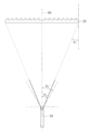
図1に示すように、光学レンズ22a、22bは、光源20と被検査対象物100の間に配置される。光源20から検出器24に向かう方向(図1における下向き方向)に見たとき、光学レンズ22a、22bは、光源20からの光50を、光源20の長手方向に対して垂直な方向に収束させる。つまり、光学レンズ22a、22bは、光源20から照射され光源20の光軸から離れる方向に広がる光を、光源20の光軸に接近する方向に収束させる。
検出器24は、光学レンズ22a、22bにより収束されて被検査対象物100のピンホール110を透過した光50を検出する。本実施形態では、光学レンズ22a、22bにより光50が収束されているため、斜めのピンホール110についても光50が透過する。
搬送装置26は、光源20の長手方向に対して垂直な方向でかつ光源20の光軸に直交する方向に被検査対象物100を移動させる。搬送装置26は、図示しない電動モータで回転するロール等を有し、被検査対象物100を搬送する。光源20から検出器24に向かう方向に見たとき、搬送装置26は、光源20の長手方向に対して垂直な方向(図1の矢印120の方向)に被検査対象物100を移動させる。なお、本実施形態において、被検査対象物100は移動するが、光源20、光学レンズ22a、22b及び検出器24は固定されている。
被検査対象物100は、帯状であり、例えば鋼板、光を透過しないフィルム、紙等とすることができる。被検査対象物100は、搬送方向(矢印120の方向)に延伸されたものであってもよい。被検査対象物100が鋼板である場合、その幅(進行方向に垂直な方向の長さ)は、例えば、50cm~1mとすることができる。
次に、本実施形態のピンホール検出装置10の製造方法(設計方法)について説明する。本実施形態では、ピンホール検出装置10の検出精度を向上するために各部の仕様を詳細に設定する。一例としての製造方法(設計方法)は下記のようなものである。
本実施形態によれば、光源20(ライン光源)の長手方向に見たとき、検出対象とするピンホール110が光源20の光軸60に対してなす最大検出可能角度をθとすると、光学繊維30が伝播可能な光50が光軸60に対してなす最大入射角θ2は、θ+0°~θ+5°の範囲に設定される。つまり、光源20の光軸60に対するピンホール110を検出可能な最大検出可能角度をθとすると、光源20の光軸60に対する光学繊維30が伝播可能な光50の最大入射角は、θ+0°~θ+5°の範囲である。これにより、検出対象とするピンホール110の検出を確実にしつつ、光学繊維30に外乱光(又は漏洩光)が入り込むことを防ぎ易くなる。その結果、透過光と外乱光の信号/雑音比(S/N比)を高めて、ピンホール110の検出精度を向上させることが可能となる。
なお、本発明は、上記実施形態に限らず、本明細書の記載内容に基づき、種々の構成を採り得ることはもちろんである。例えば、以下の構成を採用することができる。
上記実施形態では、光源20はリニア光源であったが(図1)、リニア光源以外であってもよい。上記実施形態では、1つのリニア光源を用いたが(図1)、例えば特許文献1の第5図のように複数の光源20を用いてもよい。上記実施形態では、光源20が上側、検出器24が下側であったが、逆であってもよい。
上記実施形態では、第1リニアフレネルレンズ22a及び第2リニアフレネルレンズ22bを用いた(図1)。しかしながら、その他のレンズを用いることも可能である。
上記実施形態では、光学繊維30を直線状に配置した(図1)。しかしながら、例えば、被検査対象物100の幅(光源20の長手方向における長さ)全体についてピンホール110を検出する観点からすれば、これに限らない。光学繊維30は、その他の配置で、光源20の長手方向に互いに偏位させてもよい。
上記実施形態では、被検査対象物100を移動させるために搬送装置26を用いたが(図1)、ピンホール110の検出に着目すれば、搬送装置26を設けないことも可能である。
Claims (4)
- 被検査対象物に光を照射する光源と、
前記光源と前記被検査対象物の間に配置される光学レンズと、
前記光学レンズにより収束されて前記被検査対象物のピンホールを透過した光を検出する検出器と
を有するピンホール検出装置であって、
前記検出器は、前記被検査対象物のピンホールを透過した光を伝播する光学繊維を備え、
前記光源の光軸に対する前記ピンホールを検出可能な最大検出可能角度をθとすると、前記光源の光軸に対する前記光学繊維が伝播可能な光の最大入射角は、θ+0°~θ+5°の範囲であり、
前記光源と前記検出器の間には、
前記光源の長手方向に沿って配置された前記光源側の第1リニアフレネルレンズと、 前記光源の長手方向に沿って、前記第1リニアフレネルレンズよりも前記検出器側に配置された第2リニアフレネルレンズと
が設けられ、
前記第1リニアフレネルレンズは、前記光源から出射された光を平行光になるように屈折させ、
前記第2リニアフレネルレンズは、前記光源の長手方向に見たときに前記第2リニアフレネルレンズにより屈折した光の最大偏光角が、前記光学繊維の端面に対する最大入射角と同等になる、又は前記最大入射角よりも小さくなるように前記平行光を屈折させる
ことを特徴とするピンホール検出装置。 - 前記光源は、前記被検査対象物に対して線状に光を照射するリニア光源であり、
前記光学レンズは、前記光源から照射され該光源の光軸から離れる方向に広がる光を、前記光源の光軸に接近する方向に収束させ、
前記検出器は、前記光源に対向して複数の前記光学繊維が並んで配置され、
前記光学レンズの最大偏光角をθ1とするとき、前記最大偏光角θ1を前記最大検出可能角度θ以上に設定する
ことを特徴とする請求項1に記載のピンホール検出装置。 - 前記光学繊維が伝播可能な前記光が前記光源の光軸となす最大入射角は、θ1+0°~θ1+5°の範囲に含まれる
ことを特徴とする請求項2に記載のピンホール検出装置。 - 前記光源の長手方向に対して垂直な方向でかつ前記光源の光軸に直交する方向に前記被検査対象物を移動させる搬送装置を有し、
前記被検査対象物に面する前記光学繊維の端面は、前記光学レンズの焦点位置に配置される、又は前記光学レンズの焦点位置よりも前記被検査対象物側に配置される
ことを特徴とする請求項1から請求項3のいずれか一項に記載のピンホール検出装置。
Priority Applications (8)
| Application Number | Priority Date | Filing Date | Title |
|---|---|---|---|
| JP2021079607A JP7614937B2 (ja) | 2021-05-10 | 2021-05-10 | ピンホール検出装置 |
| CN202280029381.9A CN117203517A (zh) | 2021-05-10 | 2022-03-31 | 针孔检测装置 |
| EP22807272.4A EP4339599A4 (en) | 2021-05-10 | 2022-03-31 | PINHOLE DETECTION DEVICE |
| US18/557,688 US12540903B2 (en) | 2021-05-10 | 2022-03-31 | Pinhole detection device |
| PCT/JP2022/016408 WO2022239568A1 (ja) | 2021-05-10 | 2022-03-31 | ピンホール検出装置 |
| KR1020237041538A KR20240007189A (ko) | 2021-05-10 | 2022-03-31 | 핀홀 검출 장치 |
| JP2024216265A JP7821868B2 (ja) | 2021-05-10 | 2024-12-11 | ピンホール検出装置 |
| US19/419,729 US20260168934A1 (en) | 2021-05-10 | 2025-12-15 | Pinhole detection device |
Applications Claiming Priority (1)
| Application Number | Priority Date | Filing Date | Title |
|---|---|---|---|
| JP2021079607A JP7614937B2 (ja) | 2021-05-10 | 2021-05-10 | ピンホール検出装置 |
Related Child Applications (1)
| Application Number | Title | Priority Date | Filing Date |
|---|---|---|---|
| JP2024216265A Division JP7821868B2 (ja) | 2021-05-10 | 2024-12-11 | ピンホール検出装置 |
Publications (2)
| Publication Number | Publication Date |
|---|---|
| JP2022173728A JP2022173728A (ja) | 2022-11-22 |
| JP7614937B2 true JP7614937B2 (ja) | 2025-01-16 |
Family
ID=84028259
Family Applications (2)
| Application Number | Title | Priority Date | Filing Date |
|---|---|---|---|
| JP2021079607A Active JP7614937B2 (ja) | 2021-05-10 | 2021-05-10 | ピンホール検出装置 |
| JP2024216265A Active JP7821868B2 (ja) | 2021-05-10 | 2024-12-11 | ピンホール検出装置 |
Family Applications After (1)
| Application Number | Title | Priority Date | Filing Date |
|---|---|---|---|
| JP2024216265A Active JP7821868B2 (ja) | 2021-05-10 | 2024-12-11 | ピンホール検出装置 |
Country Status (6)
| Country | Link |
|---|---|
| US (2) | US12540903B2 (ja) |
| EP (1) | EP4339599A4 (ja) |
| JP (2) | JP7614937B2 (ja) |
| KR (1) | KR20240007189A (ja) |
| CN (1) | CN117203517A (ja) |
| WO (1) | WO2022239568A1 (ja) |
Citations (5)
| Publication number | Priority date | Publication date | Assignee | Title |
|---|---|---|---|---|
| JP2003185851A (ja) | 2001-12-13 | 2003-07-03 | Moritex Corp | ラインライトガイド |
| JP2007171137A (ja) | 2005-12-26 | 2007-07-05 | Takenaka System Kiki Kk | ピンホール検出装置 |
| JP2008145423A (ja) | 2006-11-15 | 2008-06-26 | Matsushita Electric Ind Co Ltd | レーダ装置 |
| JP2009139290A (ja) | 2007-12-10 | 2009-06-25 | Jfe Steel Corp | ピンホール検出器 |
| CN209727789U (zh) | 2018-12-21 | 2019-12-03 | 深圳盟星科技股份有限公司 | 一种撕膜破损检测装置 |
Family Cites Families (22)
| Publication number | Priority date | Publication date | Assignee | Title |
|---|---|---|---|---|
| JPS504586A (ja) * | 1973-06-04 | 1975-01-17 | ||
| JPS5034586A (ja) * | 1973-07-27 | 1975-04-02 | ||
| JPS5360284A (en) * | 1976-11-11 | 1978-05-30 | Matsumoto Kikai Setsukei Jimus | Pinhole detector |
| JPS55116256U (ja) * | 1979-02-09 | 1980-08-16 | ||
| GB2109923B (en) | 1981-11-13 | 1985-05-22 | De La Rue Syst | Optical scanner |
| JPS6125042A (ja) * | 1984-07-13 | 1986-02-03 | Sumitomo Metal Ind Ltd | 表面欠陥検査装置 |
| JPH02107951A (ja) * | 1988-10-17 | 1990-04-19 | Mitsubishi Rayon Co Ltd | ピンホール検査装置 |
| JPH09257720A (ja) * | 1996-03-27 | 1997-10-03 | Matsushita Electric Ind Co Ltd | 欠陥検査方法とその装置 |
| JP3176878B2 (ja) * | 1997-11-26 | 2001-06-18 | 富士ファイン株式会社 | 欠陥検出装置 |
| JP2001188048A (ja) * | 1999-12-28 | 2001-07-10 | Kuramoto Seisakusho Co Ltd | ピンホールの検査方法 |
| JP3806616B2 (ja) * | 2001-06-04 | 2006-08-09 | 浜松ホトニクス株式会社 | ピンホール検出器 |
| KR100950964B1 (ko) * | 2002-12-26 | 2010-04-02 | 주식회사 포스코 | 레이저 광원과 apd 센서를 이용한 핀홀 검출기 |
| FR2852533B1 (fr) * | 2003-03-20 | 2006-10-06 | Arck Electronique | Dispositif de detection de trous dans des materiaux defilant en bandes continues |
| JP2004325589A (ja) * | 2003-04-22 | 2004-11-18 | Nikon Corp | スキャン測定検査装置 |
| JP5393973B2 (ja) * | 2006-11-15 | 2014-01-22 | 三菱レイヨン株式会社 | ロッドレンズアレイ検査装置及び方法 |
| HU229699B1 (hu) * | 2007-05-23 | 2014-05-28 | Mta Termeszettudomanyi Kutatokoezpont Mta Ttk | Pinhole kamerát alkalmazó, leképzõ optikai vizsgálóberendezés (reflektométer, polariméter, ellipszométer) |
| JP2010085609A (ja) * | 2008-09-30 | 2010-04-15 | Nikon Corp | 共焦点顕微鏡 |
| JP2010107408A (ja) * | 2008-10-31 | 2010-05-13 | Sumitomo Metal Mining Co Ltd | 被検体の照明装置及びそれを用いた検査装置 |
| KR101323164B1 (ko) * | 2012-03-26 | 2013-10-30 | 주식회사 져스텍 | 핀홀 플레이트와 프레넬 존 플레이트를 이용한 광학 인코더의 영점 검출 장치 |
| KR101767784B1 (ko) * | 2015-12-24 | 2017-08-14 | 주식회사 포스코 | 핀홀 또는 홀 검출 장치 및 방법 |
| CN105842257B (zh) * | 2016-05-09 | 2019-01-11 | 南京理工大学 | 一种亚微米量级的玻璃亚表面缺陷检测装置及方法 |
| CN206497055U (zh) * | 2017-02-17 | 2017-09-15 | 南京鸿照科技有限公司 | 光纤型针孔检测装置 |
-
2021
- 2021-05-10 JP JP2021079607A patent/JP7614937B2/ja active Active
-
2022
- 2022-03-31 WO PCT/JP2022/016408 patent/WO2022239568A1/ja not_active Ceased
- 2022-03-31 KR KR1020237041538A patent/KR20240007189A/ko active Pending
- 2022-03-31 EP EP22807272.4A patent/EP4339599A4/en active Pending
- 2022-03-31 CN CN202280029381.9A patent/CN117203517A/zh active Pending
- 2022-03-31 US US18/557,688 patent/US12540903B2/en active Active
-
2024
- 2024-12-11 JP JP2024216265A patent/JP7821868B2/ja active Active
-
2025
- 2025-12-15 US US19/419,729 patent/US20260168934A1/en active Pending
Patent Citations (5)
| Publication number | Priority date | Publication date | Assignee | Title |
|---|---|---|---|---|
| JP2003185851A (ja) | 2001-12-13 | 2003-07-03 | Moritex Corp | ラインライトガイド |
| JP2007171137A (ja) | 2005-12-26 | 2007-07-05 | Takenaka System Kiki Kk | ピンホール検出装置 |
| JP2008145423A (ja) | 2006-11-15 | 2008-06-26 | Matsushita Electric Ind Co Ltd | レーダ装置 |
| JP2009139290A (ja) | 2007-12-10 | 2009-06-25 | Jfe Steel Corp | ピンホール検出器 |
| CN209727789U (zh) | 2018-12-21 | 2019-12-03 | 深圳盟星科技股份有限公司 | 一种撕膜破损检测装置 |
Also Published As
| Publication number | Publication date |
|---|---|
| US12540903B2 (en) | 2026-02-03 |
| US20240210327A1 (en) | 2024-06-27 |
| WO2022239568A1 (ja) | 2022-11-17 |
| JP2025026673A (ja) | 2025-02-21 |
| JP2022173728A (ja) | 2022-11-22 |
| EP4339599A4 (en) | 2025-04-23 |
| EP4339599A1 (en) | 2024-03-20 |
| CN117203517A (zh) | 2023-12-08 |
| KR20240007189A (ko) | 2024-01-16 |
| US20260168934A1 (en) | 2026-06-18 |
| JP7821868B2 (ja) | 2026-02-27 |
Similar Documents
| Publication | Publication Date | Title |
|---|---|---|
| JP6167821B2 (ja) | 検査装置 | |
| JP6671938B2 (ja) | 表面形状測定装置、欠陥判定装置、および表面形状の測定方法 | |
| JP2010112803A5 (ja) | ||
| KR20210060466A (ko) | 시트 형상물의 결점 검사용 조명, 시트 형상물의 결점 검사 장치, 및 시트 형상물의 결점 검사 방법 | |
| CN101606094A (zh) | 用于通过照明膜进行自动检测的方法和装置 | |
| JP2013205332A (ja) | 欠点検査装置および欠点検査方法 | |
| JP5393973B2 (ja) | ロッドレンズアレイ検査装置及び方法 | |
| JP7821868B2 (ja) | ピンホール検出装置 | |
| JP2015068670A (ja) | シート状物の欠点検査装置およびシート状物の欠点検査方法 | |
| TW202244479A (zh) | 光測定裝置 | |
| JP2017125805A (ja) | シートのキズ欠点検査装置 | |
| JP2009025269A (ja) | 光透過性シートの欠点検査装置および欠点検査方法 | |
| JPH0422444B2 (ja) | ||
| JPH09281054A (ja) | ディスク表面検査方法とその装置 | |
| JP4024656B2 (ja) | 屈折計 | |
| JPS635249A (ja) | 面状体の欠陥検出方法 | |
| JP2005181452A (ja) | 光学装置 | |
| JPH032254B2 (ja) | ||
| JP2003240726A (ja) | シートの欠点検出装置 | |
| JP3358674B2 (ja) | ピンホール検出方法およびピンホール検出装置 | |
| JPH045556A (ja) | 球体表面の傷検査装置 | |
| SU329449A1 (ru) | УСТРОЙСТВО дл ОБНАРУЖЕНИЯ ДЕФЕКТОВ В ПОЛОТНЕ ВОЛОКНИСТОГО МАТЕРИАЛА | |
| JPS62280643A (ja) | 面状体の欠陥検出方法 | |
| JPH0432752A (ja) | 表面検査装置 | |
| JPS62280644A (ja) | 面状体の欠陥検出方法 |
Legal Events
| Date | Code | Title | Description |
|---|---|---|---|
| A621 | Written request for application examination |
Free format text: JAPANESE INTERMEDIATE CODE: A621 Effective date: 20240119 |
|
| A131 | Notification of reasons for refusal |
Free format text: JAPANESE INTERMEDIATE CODE: A131 Effective date: 20241015 |
|
| A521 | Request for written amendment filed |
Free format text: JAPANESE INTERMEDIATE CODE: A523 Effective date: 20241211 |
|
| TRDD | Decision of grant or rejection written | ||
| A01 | Written decision to grant a patent or to grant a registration (utility model) |
Free format text: JAPANESE INTERMEDIATE CODE: A01 Effective date: 20241217 |
|
| A61 | First payment of annual fees (during grant procedure) |
Free format text: JAPANESE INTERMEDIATE CODE: A61 Effective date: 20241227 |
|
| R150 | Certificate of patent or registration of utility model |
Ref document number: 7614937 Country of ref document: JP Free format text: JAPANESE INTERMEDIATE CODE: R150 |