JP7614960B2 - Switchboard and method for mounting IED on switchboard - Google Patents
Switchboard and method for mounting IED on switchboard Download PDFInfo
- Publication number
- JP7614960B2 JP7614960B2 JP2021111997A JP2021111997A JP7614960B2 JP 7614960 B2 JP7614960 B2 JP 7614960B2 JP 2021111997 A JP2021111997 A JP 2021111997A JP 2021111997 A JP2021111997 A JP 2021111997A JP 7614960 B2 JP7614960 B2 JP 7614960B2
- Authority
- JP
- Japan
- Prior art keywords
- frame
- ied
- switchboard
- notch
- disposed
- Prior art date
- Legal status (The legal status is an assumption and is not a legal conclusion. Google has not performed a legal analysis and makes no representation as to the accuracy of the status listed.)
- Active
Links
Images


Landscapes
- Patch Boards (AREA)
Description
本発明の実施形態は、配電盤および配電盤に対するIEDの実装方法に関する。 An embodiment of the present invention relates to a switchboard and a method for mounting an IED on the switchboard.
デジタル変電所システム等の電力系統で、IED(Intelligent Electronic Device)を実装した配電盤が利用される。配電盤には、IEDを効率よく実装することが求められる。 In power systems such as digital substation systems, switchboards equipped with IEDs (Intelligent Electronic Devices) are used. Switchboards are required to efficiently implement IEDs.
本発明が解決しようとする課題は、IEDを効率よく実装することができる配電盤および配電盤に対するIEDの実装方法を提供することである。 The problem that this invention aims to solve is to provide a switchboard that can efficiently mount an IED and a method for mounting an IED on a switchboard.
実施形態の配電盤は、第1フレームと、第2フレームと、取付け部と、を持つ。第1フレームは、幅方向の端部に配置され、上下方向に伸び、幅方向の内側縁部に沿った切欠きを有する。第2フレームは、幅方向に伸び、幅方向の端部が第1フレームに固定され、第1フレームの切欠きの上下方向に配置される。取付け部は、IEDの上下方向に配置され、第2フレームに固定される。 The switchboard of the embodiment has a first frame, a second frame, and an attachment portion. The first frame is disposed at the end in the width direction, extends in the vertical direction, and has a notch along the inner edge in the width direction. The second frame extends in the width direction, has an end in the width direction fixed to the first frame, and is disposed above and below the notch of the first frame. The attachment portion is disposed above and below the IED, and is fixed to the second frame.
以下、実施形態の配電盤および配電盤に対するIEDの実装方法を、図面を参照して説明する。
図1は、第1の実施形態の配電盤の斜視図である。本願において、直交座標系のX方向、Y方向およびZ方向が以下のように定義される。X方向は、配電盤100の幅方向である。配電盤100のX方向の中心側をX方向の内側と呼び、中心とは反対側をX方向の外側と呼ぶ場合がある。Y方向は、配電盤100の奥行方向である。+Y方向は、配電盤100の後方向(正面から背面に向かう方向)である。Z方向は上下方向(鉛直方向)であり、+Z方向は上方向である。
Hereinafter, a switchboard according to an embodiment and a method for mounting an IED on the switchboard will be described with reference to the drawings.
1 is a perspective view of a switchboard of a first embodiment. In this application, the X direction, Y direction, and Z direction of the Cartesian coordinate system are defined as follows. The X direction is the width direction of the
配電盤100には、IED(Intelligent Electronic Device)1が実装される。IED1には、複数のDIO(デジタル入出力)基板が搭載される。DIO基板は、IED1の-Y方向の正面から、IED1の内部の基板スロットに挿入される。DIO基板の挿入後のIED1の正面は、カバーで覆われる。IED1は、制御端末または保護端末などとして機能する。制御端末は、電力系統の電流または電圧などを計測すると共に、遮断器や断路器などの動作信号を出力して制御する。保護端末は、遮断器などの動作信号を出力して、電力系統を保護する。
An IED (Intelligent Electronic Device) 1 is mounted on the
EIA/ECA規格のEIA/ECA-310-Eでは、IED1のX方向の長さ(ケース2の±X面に装着されたフランジを含むX方向の長さ)について、19インチが標準とされている。IED1として、X方向の長さが19インチの1/1型のほか、3/4型、1/2型、1/3型および1/6型が準備されている。 In the EIA/ECA standard EIA/ECA-310-E, the standard length of the IED1 in the X direction (the length in the X direction including the flanges attached to the ±X faces of the case 2) is 19 inches. In addition to the 1/1 type with an X direction length of 19 inches, the IED1 is available in 3/4 type, 1/2 type, 1/3 type, and 1/6 type.
一方、日本国内の変電所等に設置されている標準的な配電盤のX方向の長さは、350mmまたは700mmである。配電盤のX方向の長さは、X方向の端部に配置される第1フレーム10のX方向の外側の間隔である。これらの配電盤に対して、EIA/ECA-310-Eに準拠したIED1を、効率よく実装することが求められる。
Meanwhile, the length in the X direction of standard switchboards installed in substations and the like in Japan is 350 mm or 700 mm. The length in the X direction of the switchboard is the outer distance in the X direction of the
(第1の実施形態)
第1の実施形態では、X方向の長さが350mmの配電盤100に対して、3/4型のIED1が実装される。配電盤100におけるIED1の配列は、Z方向に2行およびY方向に1列である。IED1の配列は、Z方向に1行でもよいし、Z方向に3行以上でもよい。
配電盤100は、第1フレーム10と、第2フレーム20と、第3フレーム30と、第4フレーム40(図7参照)と、IED1と、取付け部50と、正面パネル60(図7参照)と、を有する。
(First embodiment)
In the first embodiment, a 3/4-
The
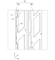
図2は、第1フレームの斜視図である。
第1フレーム10は、X方向の端部に配置される。一対の第1フレーム10a,10bが、X方向の両端部に配置される。第1フレーム10は、Z方向に伸びる。第1フレーム10は、第1板11および第2板12を有する。第1板11はXZ平面と平行であり、第2板12はYZ平面と平行である。第1板11は、第2板12の-Y方向の端部からX方向の内側に伸びる。第1フレーム10は、切欠き16を有する。切欠き16は、第1フレーム10の第1板11のX方向の内側縁部に沿って形成される。切欠き16はZ方向に伸びる。切欠き16のZ方向の長さは、IED1のケース2のZ方向の長さより大きい。第1フレーム10のX方向の開口幅F1(図1参照)と、一対の切欠き16のX方向の長さとの和は、ケース2のX方向の長さCより大きい。
FIG. 2 is a perspective view of the first frame.
The
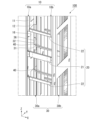
図3は、IEDの実装前の配電盤の斜視図である。
第2フレーム20は、X方向に伸びる。第2フレーム20のX方向に垂直な断面は、+Y方向が開口するU字状に形成される。第2フレーム20は、第1フレーム10の切欠き16の±Z方向に配置される。第2フレーム20は、第1フレーム10の第1板11の+Y方向に隣接して配置される。第2フレーム20は、一対の第1フレーム10a,10bのX方向の内側に配置される。第2フレーム20のX方向の端部は、第1フレーム10の第1板11および第2板12に対して、溶接により固定される。第2フレーム20のX方向の端部は、第1フレーム10に対して溶接以外の方法により固定されてもよい。第2フレーム20は、配電盤100の剛性を増加させる。第2フレーム20は、配電盤100の耐震強度を増加させる。
FIG. 3 is a perspective view of a switchboard before an IED is mounted thereon.
The
第2フレーム20は、内側第2フレーム21および外側第2フレーム22を有する。図1に示されるように、内側第2フレーム21は、Z方向に並ぶIED1のZ方向の内側に配置される。外側第2フレーム22は、Z方向に並ぶIED1のZ方向の外側に配置される。図3に示されるように、内側第2フレーム21のZ方向の長さは、外側第2フレーム22のZ方向の長さの2倍程度である。
The
第3フレーム30は、Z方向に伸びる。第3フレーム30は、第1フレーム10のX方向の内側に配置される。一対の第1フレーム10a,10bのX方向の内側に、一対の第3フレーム30a,30bが配置される。第3フレーム30は、第2フレーム20の+Y方向に配置される。第3フレーム30は、第1フレーム10のY方向の中間部に配置される。
The
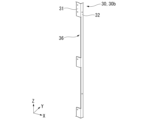
図4は、第3フレーム30の斜視図である。第3フレーム30は、第1板31および第2板32を有する。第1板31はXZ平面と平行であり、第2板32はYZ平面と平行である。第1板31は、第2板32の-Y方向の端部からX方向の内側に伸びる。第3フレーム30の第2板32は、第1フレーム10の第2板12(図3参照)に固定される。第3フレーム30は、切欠き36を有する。切欠き36は、第3フレーム30の第1板31のX方向の内側縁部に沿って形成される。切欠き36はZ方向に伸びる。切欠き36のZ方向の長さは、IED1のケース2のZ方向の長さより大きい。図3に示されるように、第3フレーム30の切欠き36のZ方向の位置は、第1フレーム10の切欠き16と同じである。第3フレーム30のX方向の開口幅と、一対の切欠き36のX方向の長さとの和は、ケース2のX方向の長さより大きい。
Figure 4 is a perspective view of the
第4フレーム40は、X方向に伸びる。第4フレーム40は、第3フレーム30の切欠き36の-Z方向に配置される。第4フレーム40は、第3フレーム30のX方向の内側に配置される。
図5は、第4フレーム40の背面側の斜視図である。第4フレーム40は、第1板41および第2板42を有する。第1板41はXZ平面と平行であり、第2板42はXY平面と平行である。第2板42は、第1板41の+Z方向の端部から-Y方向に伸びる。第2板42のX方向の長さは、第3フレーム30(図3参照)のX方向の内側縁部の間隔より小さい。
The
5 is a perspective view of the rear side of the
図6は、配電盤の背面側の斜視図である。図6には、配電盤の+Y方向の一部が切断された状態が図示されている。第4フレーム40のX方向の端部は、第3フレーム30に対してネジ止めにより固定される。第4フレーム40のX方向の端部は、第3フレーム30に対してネジ止め以外の方法により固定されてもよい。第4フレーム40は、配電盤100の剛性を増加させる。第4フレーム40は、配電盤100の輸送時等の振動を抑制する。第4フレーム40は、IED1のケース2の-Z面に当接する。
Figure 6 is a perspective view of the rear side of the switchboard. Figure 6 illustrates a state in which a portion of the switchboard in the +Y direction has been cut off. The X-direction end of the
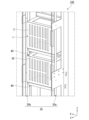
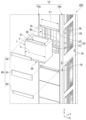
図7は、第1の実施形態の配電盤に対するIEDの実装方法の説明図である。
取付け部50は、IED1のケース2の±Z面にネジ止め等により固定される。取付け部50は、±Z方向に伸びるフランジ51を有する。ケース2の+Z面に固定される取付け部50のフランジ51は、ケース2から+Z方向に伸びる。ケース2の-Z面に固定される取付け部50のフランジ51は、ケース2から-Z方向に伸びる。フランジ51は、ケース2の-Y方向の端部に配置される。フランジ51は、XZ平面と平行である。フランジ51のX方向の長さは、第1フレーム10のX方向の開口幅より小さい。フランジ51のZ方向の長さは、外側第2フレーム22のZ方向の長さより小さい。
FIG. 7 is an explanatory diagram of a method of mounting an IED on a switchboard according to the first embodiment.
The mounting
IED1のケース2は、第1フレーム10のX方向の内側および第2フレーム20のZ方向の内側の領域に対して、配電盤100の-Y方向の正面から+Y方向に挿入される。ケース2のX方向の外側端部が、第1フレーム10の切欠き16および第3フレーム30の切欠き36の内側に配置される。ケース2のX方向の外側端部と第1フレーム10および第3フレーム30との干渉が、切欠き16および切欠き36により回避される。ケース2の-Z面が、第2フレーム20および第4フレーム40により支持される。フランジ51は、第2フレーム20の-Y面に対して、ネジ止めにより固定される。
The
配電盤100に対して、複数のIED1が個別に実装される。第2フレーム20に対するフランジ51のネジ止めを取り外すことにより、各IED1を個別に引き出すことができる。これにより、各IED1を個別にメンテナンスすることができる。
正面パネル60は、XZ平面と平行である。正面パネル60は、内側正面パネル61および外側正面パネル62を有する。内側正面パネル61は、Z方向に並ぶIED1のZ方向の内側に配置される。外側正面パネル62は、Z方向に並ぶIED1のZ方向の外側に配置される。正面パネル60のX方向およびZ方向の長さは、第2フレーム20と同等である。正面パネル60は、フランジ51および第1フレーム10を挟んで、第2フレーム20の反対側に配置される。正面パネル60は、ネジ止めにより、第1フレーム10および第2フレーム20に固定される。正面パネル60は、配電盤100の剛性を増加させる。
The
複数の配電盤100をX方向に連結する場合がある。第1フレーム10の貫通孔18に締結部材を挿入して、複数の配電盤100が連結される。貫通孔18は、第1フレーム10の第2板12に形成され、第1フレーム10をX方向に貫通する。貫通孔18は、第1フレーム10のY方向の両端部に形成される。-Y方向の貫通孔18がIED1のケース2により閉塞されて、貫通孔18への締結部材の挿入が困難になる場合がある。第1フレーム10をX方向に貫通する新しい貫通孔19が形成される。貫通孔19は、第2フレーム20の+Y方向に形成される。IED1および第2フレームはZ方向に交互に配置されるので、貫通孔19はIED1により閉塞されない。新しい貫通孔19および+Y方向の貫通孔18に締結部材を挿入して、複数の配電盤100が連結される。
In some cases,
配電盤100に対するIED1の実装方法について説明する。
図2に示されるように、配電盤100の第1フレーム10に、X方向の内側縁部に沿った切欠き16が形成される。切欠き16のZ方向の長さは、IED1のケース2のZ方向の長さより大きい。図3に示されるように、X方向に伸びる第2フレーム20が、切欠き16の±Z方向に配置される。第2フレーム20のX方向の端部が、第1フレーム10に固定される。
A method of mounting the
As shown in Fig. 2, a
配電盤100の第3フレーム30に、X方向の内側縁部に沿った切欠き36が形成される。切欠き36のZ方向の長さは、IED1のケース2のZ方向の長さより大きい。X方向に伸びる第4フレーム40が、切欠き36の-Z方向に配置される。第4フレーム40のX方向の端部が、第3フレーム30に固定される。
A
図7に示されるように、IED1のケース2の±Z面に、取付け部50が固定される。IED1のケース2が、第1フレーム10のX方向の内側および第2フレーム20のZ方向の内側の領域に挿入される。取付け部50のフランジ51が、第2フレーム20に固定される。正面パネル60が、第1フレーム10および第2フレーム20に固定される。以上により、配電盤100に対するIED1の実装が完了する。
As shown in FIG. 7, the mounting
以上に詳述されたように、実施形態の配電盤100は、第1フレーム10と、第2フレーム20と、取付け部50と、を持つ。第1フレーム10は、X方向の端部に配置され、Z方向に伸び、X方向の内側縁部に沿った切欠き16を有する。第2フレーム20は、X方向に伸び、X方向の端部が第1フレーム10に固定され、第1フレーム10の切欠き16の±Z方向に配置される。取付け部50は、IED1の±Z方向に配置され、第2フレーム20に固定される。
As described above in detail, the
IED1のケース2のX方向の長さが、第1フレーム10のX方向の開口幅より大きい。実施形態の配電盤100では、第1フレーム10が切欠き16を有するので、第1フレーム10のX方向の内側にIED1のケース2が配置される。多くのDIO基板を搭載したIED1が、配電盤100に対して効率よく実装される。
The length in the X direction of the
第1フレーム10に切欠き16を形成すると、第1フレーム10に対するIED1の固定が困難になる。実施形態の配電盤100では、切欠き16の±Z方向に配置された第2フレーム20に、IED1の±Z方向に配置された取付け部50が固定される。これにより、配電盤100に対してIED1が固定される。
If the
配電盤100は、第3フレーム30と、第4フレーム40と、を有する。第3フレーム30は、第2フレーム20の+Y方向に配置され、Z方向に伸び、X方向の内側縁部に沿った切欠き36を有する。第4フレーム40は、X方向に伸び、X方向の端部が第3フレーム30に固定され、第3フレーム30の切欠き36の-Z方向に配置される。
The
第3フレーム30が切欠き36を有するので、第3フレーム30のX方向の内側にIED1のケース2が配置される。第4フレーム40が切欠き36の-Z方向に配置されるので、IED1の-Z面が第2フレーム20および第4フレーム40に支持される。これにより、第2フレーム20に対する取付け部50の固定作業が容易になる。
Because the
第2フレーム20は、第1フレーム10に対して溶接により固定されている。
これにより、配電盤100の剛性が増加する。
The
This increases the rigidity of the
取付け部50は、IED1の±Z面に固定され、Z方向に伸びるフランジ51を有する。
取付け部50は、フランジ51により第2フレーム20に固定される。
The mounting
The mounting
第1フレーム10は、第2フレーム20の+Y方向に、第1フレーム10をX方向に貫通する貫通孔19を有する。
第2フレーム20およびIED1は、Z方向に交互に配置される。第2フレーム20の+Y方向に形成された貫通孔19は、IED1により閉塞されない。貫通孔19に締結部材を挿入して、複数の配電盤100がX方向に連結される。
The
The second frames 20 and the
(第2の実施形態)
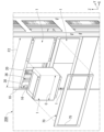
図8は、第2の実施形態の配電盤に対するIEDの実装方法の説明図である。
第2の実施形態では、X方向の長さが700mmの配電盤200に対して、3/4型のIED1が実装される。配電盤200におけるIED1の配列は、Z方向に2行およびY方向に2列である。IED1の配列は、Z方向に1行でもよいし、Z方向に3行以上でもよい。第1の実施形態と同様である部分の第2の実施形態の説明は、省略される場合がある。
Second Embodiment
FIG. 8 is an explanatory diagram of a method of mounting an IED on a switchboard according to the second embodiment.
In the second embodiment, a 3/4-
第1フレーム10のX方向の内側に、2個のIED1のケース2がX方向に並んで配置される。2個のIED1のケース2のX方向の外側端部が、第1フレーム10の切欠き16および第3フレーム30の切欠き36の内側に配置される。第1フレーム10のX方向の開口幅F2と、一対の切欠き16のX方向の長さとの和は、第1フレーム10のX方向の内側に配置される2個のIED1のケース2のX方向の長さより大きい。第3フレーム30のX方向の開口幅と、一対の切欠き36のX方向の長さとの和は、第3フレーム30のX方向の内側に配置される2個のIED1のケース2のX方向の長さより大きい。
The
正面パネル70は、XZ平面と平行である。正面パネル70は、四角形の額縁状に形成される。正面パネル70の開口75のX方向の長さは、切欠き16の形成部分における第1フレーム10のX方向の間隔と同じである。正面パネル70の開口75のZ方向の長さは、第2フレーム20のZ方向の間隔と同じである。X方向に並んだ2個のIED1は、正面パネル70の開口75から-Y方向に露出する。正面パネル70は、第1フレーム10およびフランジ51の-Y方向に配置される。正面パネル70は、ネジ止めにより、第1フレーム10および第2フレーム20に固定される。正面パネル70は、配電盤200の剛性を増加させる。
The
以上のように、第2の実施形態の配電盤200では、第1フレーム10の間に、IED1が並んで配置される。
複数のIED1のケース2をX方向に並べたときのX方向の長さが、第1フレーム10のX方向の開口幅より大きい。配電盤200では、第1フレーム10が切欠き16を有するので、第1フレーム10のX方向の内側に複数のIED1のケース2が配置される。多くのDIO基板を搭載した複数のIED1が、配電盤200に対して効率よく実装される。
As described above, in the
When the
以上説明した少なくともひとつの実施形態によれば、第1フレーム10の切欠き16を持つことにより、配電盤に対してIED1を効率的に実装することができる。
According to at least one of the embodiments described above, the
本発明のいくつかの実施形態を説明したが、これらの実施形態は、例として提示したものであり、発明の範囲を限定することは意図していない。これら実施形態は、その他の様々な形態で実施されることが可能であり、発明の要旨を逸脱しない範囲で、種々の省略、置き換え、変更を行うことができる。これら実施形態やその変形は、発明の範囲や要旨に含まれると同様に、特許請求の範囲に記載された発明とその均等の範囲に含まれるものである。 Although several embodiments of the present invention have been described, these embodiments are presented as examples and are not intended to limit the scope of the invention. These embodiments can be implemented in various other forms, and various omissions, substitutions, and modifications can be made without departing from the gist of the invention. These embodiments and their modifications are within the scope of the invention and its equivalents as set forth in the claims, as well as the scope and gist of the invention.
1…IED、2…ケース、10…第1フレーム、16…切欠き、19…貫通孔、20…第2フレーム、30…第3フレーム、36…切欠き、40…第4フレーム、50…取付け部、51…フランジ、100,200…配電盤。 1...IED, 2...case, 10...first frame, 16...notch, 19...through hole, 20...second frame, 30...third frame, 36...notch, 40...fourth frame, 50...mounting portion, 51...flange, 100, 200...distribution board.
Claims (6)
前記幅方向に伸び、前記幅方向の端部が前記第1フレームに固定され、前記第1フレームの切欠きの上下方向に配置される第2フレームと、
IEDの上下方向に配置され、前記第2フレームに固定される取付け部と、を有する、
配電盤。 a first frame disposed at an end in a width direction, extending in a vertical direction, and having a notch along an inner edge portion in the width direction;
a second frame extending in the width direction, an end portion in the width direction being fixed to the first frame, and disposed above and below the notch of the first frame;
and a mounting portion disposed in a vertical direction of the IED and fixed to the second frame.
Distribution board.
前記幅方向に伸び、前記幅方向の端部が前記第3フレームに固定され、前記第3フレームの切欠きの下方向に配置される第4フレームと、を有する、
請求項1に記載の配電盤。 a third frame disposed behind the second frame, extending in a vertical direction, and having a notch along an inner edge portion in the width direction;
a fourth frame extending in the width direction, an end portion in the width direction being fixed to the third frame, and disposed below the notch of the third frame;
The switchboard according to claim 1 .
請求項1または2に記載の配電盤。 The mounting portion is fixed to the upper and lower surfaces of the IED and has flanges extending in the vertical direction.
A switchboard according to claim 1 or 2.
請求項1から3のいずれか1項に記載の配電盤。 The first frame has a through hole penetrating the first frame in the width direction at the rear of the second frame.
A switchboard according to any one of claims 1 to 3.
請求項1から4のいずれか1項に記載の配電盤。 The IEDs are arranged side by side between the first frames.
A switchboard according to any one of claims 1 to 4.
前記幅方向に伸びる第2フレームを、前記第1フレームの切欠きの上下方向に配置して、前記第1フレームに固定し、
IEDの上下方向に配置した取付け部を、前記第2フレームに固定する、
配電盤に対するIEDの実装方法。 A first frame extending in a vertical direction and disposed at an end in a width direction of the switchboard is provided with a notch along an inner edge portion in the width direction;
a second frame extending in the width direction is disposed above and below the notch of the first frame and fixed to the first frame;
Fixing a mounting portion disposed in the up-down direction of the IED to the second frame;
How to implement an IED on a switchboard.
Priority Applications (1)
| Application Number | Priority Date | Filing Date | Title |
|---|---|---|---|
| JP2021111997A JP7614960B2 (en) | 2021-07-06 | 2021-07-06 | Switchboard and method for mounting IED on switchboard |
Applications Claiming Priority (1)
| Application Number | Priority Date | Filing Date | Title |
|---|---|---|---|
| JP2021111997A JP7614960B2 (en) | 2021-07-06 | 2021-07-06 | Switchboard and method for mounting IED on switchboard |
Publications (2)
| Publication Number | Publication Date |
|---|---|
| JP2023008437A JP2023008437A (en) | 2023-01-19 |
| JP7614960B2 true JP7614960B2 (en) | 2025-01-16 |
Family
ID=85111921
Family Applications (1)
| Application Number | Title | Priority Date | Filing Date |
|---|---|---|---|
| JP2021111997A Active JP7614960B2 (en) | 2021-07-06 | 2021-07-06 | Switchboard and method for mounting IED on switchboard |
Country Status (1)
| Country | Link |
|---|---|
| JP (1) | JP7614960B2 (en) |
Citations (1)
| Publication number | Priority date | Publication date | Assignee | Title |
|---|---|---|---|---|
| JP2018067636A (en) | 2016-10-19 | 2018-04-26 | 河村電器産業株式会社 | Cabinet for housing electrical equipment |
-
2021
- 2021-07-06 JP JP2021111997A patent/JP7614960B2/en active Active
Patent Citations (1)
| Publication number | Priority date | Publication date | Assignee | Title |
|---|---|---|---|---|
| JP2018067636A (en) | 2016-10-19 | 2018-04-26 | 河村電器産業株式会社 | Cabinet for housing electrical equipment |
Also Published As
| Publication number | Publication date |
|---|---|
| JP2023008437A (en) | 2023-01-19 |
Similar Documents
| Publication | Publication Date | Title |
|---|---|---|
| KR101829126B1 (en) | Distribution Panel with Vibration Proof | |
| EP0797911B1 (en) | Grounding and screening device | |
| JP7614960B2 (en) | Switchboard and method for mounting IED on switchboard | |
| JPS6054030A (en) | Terminating frame assembly | |
| KR20170034123A (en) | Power distribution device using block for assembly | |
| JP5826312B2 (en) | Housing mounting structure and mounting tool used therefor | |
| RU2335835C1 (en) | Connector module | |
| RU141890U1 (en) | FASTENING AND SEPARATING UNIT FOR DISTRIBUTION SHIELD | |
| US6407926B1 (en) | Apparatus for mounting electronic circuits in electric power equipment enclosures | |
| EP4175429A1 (en) | Half-width node and electronic device | |
| JP2006238562A (en) | Plug-in distribution board | |
| EP3748791B1 (en) | Vertical bus line support device | |
| US7136277B2 (en) | Basepan assembly | |
| US20080158786A1 (en) | Panelboards having support rails | |
| JP3104894B2 (en) | Closed switchboard | |
| JP4625385B2 (en) | switchboard | |
| JP2016082851A (en) | Residential distribution board | |
| KR102232676B1 (en) | Distribution Panel with Vibration Proof for Improving Fastening Force of Elastic Body | |
| JP7628366B2 (en) | Distribution boards and covering materials | |
| JP6771702B1 (en) | Switchboard equipment | |
| JP7492353B2 (en) | How to connect the board | |
| CN216016009U (en) | Mounting bracket and block terminal | |
| KR200426215Y1 (en) | Bus Bar Assembly | |
| JP7183650B2 (en) | Bus bar support device | |
| JP2010287821A (en) | Heat sink fitting structure |
Legal Events
| Date | Code | Title | Description |
|---|---|---|---|
| A621 | Written request for application examination |
Free format text: JAPANESE INTERMEDIATE CODE: A621 Effective date: 20240301 |
|
| A977 | Report on retrieval |
Free format text: JAPANESE INTERMEDIATE CODE: A971007 Effective date: 20241126 |
|
| TRDD | Decision of grant or rejection written | ||
| A01 | Written decision to grant a patent or to grant a registration (utility model) |
Free format text: JAPANESE INTERMEDIATE CODE: A01 Effective date: 20241203 |
|
| A61 | First payment of annual fees (during grant procedure) |
Free format text: JAPANESE INTERMEDIATE CODE: A61 Effective date: 20241227 |
|
| R150 | Certificate of patent or registration of utility model |
Ref document number: 7614960 Country of ref document: JP Free format text: JAPANESE INTERMEDIATE CODE: R150 |