JP7615519B2 - Ultra-compact relay with high creepage distance - Google Patents
Ultra-compact relay with high creepage distance Download PDFInfo
- Publication number
- JP7615519B2 JP7615519B2 JP2023524334A JP2023524334A JP7615519B2 JP 7615519 B2 JP7615519 B2 JP 7615519B2 JP 2023524334 A JP2023524334 A JP 2023524334A JP 2023524334 A JP2023524334 A JP 2023524334A JP 7615519 B2 JP7615519 B2 JP 7615519B2
- Authority
- JP
- Japan
- Prior art keywords
- plastic body
- contact spring
- movable contact
- armature
- creepage distance
- Prior art date
- Legal status (The legal status is an assumption and is not a legal conclusion. Google has not performed a legal analysis and makes no representation as to the accuracy of the status listed.)
- Active
Links
Images


Classifications
-
- H—ELECTRICITY
- H01—ELECTRIC ELEMENTS
- H01H—ELECTRIC SWITCHES; RELAYS; SELECTORS; EMERGENCY PROTECTIVE DEVICES
- H01H50/00—Details of electromagnetic relays
- H01H50/54—Contact arrangements
- H01H50/56—Contact spring sets
-
- H—ELECTRICITY
- H01—ELECTRIC ELEMENTS
- H01H—ELECTRIC SWITCHES; RELAYS; SELECTORS; EMERGENCY PROTECTIVE DEVICES
- H01H50/00—Details of electromagnetic relays
- H01H50/02—Bases; Casings; Covers
- H01H50/04—Mounting complete relay or separate parts of relay on a base or inside a case
-
- H—ELECTRICITY
- H01—ELECTRIC ELEMENTS
- H01H—ELECTRIC SWITCHES; RELAYS; SELECTORS; EMERGENCY PROTECTIVE DEVICES
- H01H50/00—Details of electromagnetic relays
- H01H50/14—Terminal arrangements
-
- H—ELECTRICITY
- H01—ELECTRIC ELEMENTS
- H01H—ELECTRIC SWITCHES; RELAYS; SELECTORS; EMERGENCY PROTECTIVE DEVICES
- H01H50/00—Details of electromagnetic relays
- H01H50/16—Magnetic circuit arrangements
- H01H50/18—Movable parts of magnetic circuits, e.g. armature
- H01H50/24—Parts rotatable or rockable outside coil
-
- H—ELECTRICITY
- H01—ELECTRIC ELEMENTS
- H01H—ELECTRIC SWITCHES; RELAYS; SELECTORS; EMERGENCY PROTECTIVE DEVICES
- H01H50/00—Details of electromagnetic relays
- H01H50/54—Contact arrangements
- H01H50/56—Contact spring sets
- H01H50/58—Driving arrangements structurally associated therewith; Mounting of driving arrangements on armature
-
- H—ELECTRICITY
- H01—ELECTRIC ELEMENTS
- H01H—ELECTRIC SWITCHES; RELAYS; SELECTORS; EMERGENCY PROTECTIVE DEVICES
- H01H1/00—Contacts
- H01H1/12—Contacts characterised by the manner in which co-operating contacts engage
- H01H1/14—Contacts characterised by the manner in which co-operating contacts engage by abutting
- H01H1/24—Contacts characterised by the manner in which co-operating contacts engage by abutting with resilient mounting
-
- H—ELECTRICITY
- H01—ELECTRIC ELEMENTS
- H01H—ELECTRIC SWITCHES; RELAYS; SELECTORS; EMERGENCY PROTECTIVE DEVICES
- H01H50/00—Details of electromagnetic relays
- H01H50/02—Bases; Casings; Covers
- H01H50/04—Mounting complete relay or separate parts of relay on a base or inside a case
- H01H50/041—Details concerning assembly of relays
- H01H50/043—Details particular to miniaturised relays
-
- H—ELECTRICITY
- H01—ELECTRIC ELEMENTS
- H01H—ELECTRIC SWITCHES; RELAYS; SELECTORS; EMERGENCY PROTECTIVE DEVICES
- H01H50/00—Details of electromagnetic relays
- H01H50/02—Bases; Casings; Covers
- H01H50/04—Mounting complete relay or separate parts of relay on a base or inside a case
- H01H50/047—Details concerning mounting a relays
- H01H50/048—Plug-in mounting or sockets
Landscapes
- Physics & Mathematics (AREA)
- Electromagnetism (AREA)
- Electromagnets (AREA)
Description
関連出願の相互参照
本開示は、2020年12月30日に出願された出願番号が202011609586.3である中国特許出願の優先権を主張し、当該中国特許出願の内容の全体を本願に援用する。
CROSS-REFERENCE TO RELATED APPLICATIONS This disclosure claims priority to Chinese patent application No. 202011609586.3, filed on December 30, 2020, the contents of which are incorporated herein by reference in their entirety.
本開示はリレー技術分野に関し、特に高い沿面距離を有する超小型リレーに関する。 This disclosure relates to the field of relay technology, and in particular to ultra-compact relays with long creepage distances.
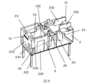
従来の超小型リレーは、一般的には切断された固定接点ばね片を射出成形方式によってコイル、台座等と一体に接続し、固定接点ばね片の引出端子及びコイル端子の引出端子は射出成形された切断シート体を利用して折り曲げて形成され、このような超小型リレーの各引出端子は一般的にはコイル軸線の両側に沿って分布する。図1は従来技術の超小型リレーの立体構造概略図(ハウジングを含まない)である。図2は従来技術の超小型リレーの可動接点ばねとアーマチュアの組み合わせの構造概略図である。図3は従来技術の超小型リレーの台座部分の構造概略図である。図1、図2、図3に示すように、従来技術のこのような超小型リレーは、コイル、鉄心101、固定接点ばね及びコイル端子102を射出成形方式で一体に組み立ててプラスチック体109を含む台座部分100を形成し、ここで、固定接点ばねは2つの常開固定接点ばね片103、2つの常閉固定接点ばね片104及び2つの共通端ばね片105を含む。常開固定接点ばね片103、常閉固定接点ばね片104及び共通端ばね片105には、それぞれプラスチック体109の外に露出する常開固定接点ばね引出端子1031、常閉固定接点ばね引出端子1041、共通端引出端子1051が設けられる。常開固定接点ばね片103、常閉固定接点ばね片104のプラスチック体の上端に露出する部分には、さらにそれぞれ常開固定接点1032、常閉固定接点1042が接続される。このような超小型リレーの可動接点ばねとアーマチュアの組み合わせ106は二組の可動接点ばね片107とアーマチュア108を射出成形方式によってプラスチック部品110を含む一体構造に形成し、各組の可動接点ばね片107の両端はそれぞれプラスチック部品110の外に露出する常開側1071と常閉側1072とし、中間にプラスチック部品110の外に露出する溶接ラグ構造1073が設けられ、可動接点ばね片107の常開側1071及び常閉側1072にそれぞれ常開可動接点及び常閉可動接点が取り付けられる。可動接点ばねとアーマチュアの組み合わせ106を台座部分100に取り付ける際には、可動接点ばねとアーマチュアの組み合わせ106の溶接ラグ構造1073と台座部分100の共通端ばね片105の溶接台とを溶接によって一体に固定し、これにより可動接点ばねとアーマチュアの組み合わせ106がシーソー構造を呈する。台座部分100において、コイル端子102の引出端子1021はプラスチック体109の一端に位置し、常閉固定接点ばね引出端子1041、共通端引出端子1051及び常開固定接点ばね引出端子1031は、順にプラスチック体109の一端からプラスチック体109の他端の方向へ分布し、常開固定接点ばね引出端子1031はプラスチック体109の他端に位置する。従来技術のこのような超小型リレーは、図3に示すように、製品の体積が小さく、全体構造がコンパクトであるため、コイル端子102と固定接点ばね(常閉固定接点ばね片104)との間の沿面距離M及びコイル端子102と固定接点(常閉固定接点1042)との間の沿面距離Nがいずれも短いという弊害をもたらし、新エネルギー、車載等の分野におけるリレーの入力及び出力(即ちコイルと接点との間)に対してますます高くなる安全要件(即ち高い沿面距離)を満たすことができない。
Conventional microminiature relays generally have cut fixed contact spring pieces integrally connected to the coil, base, etc. by injection molding, and the lead terminals of the fixed contact spring pieces and the lead terminals of the coil terminals are formed by folding an injection-molded cut sheet body, and the lead terminals of such microminiature relays are generally distributed along both sides of the coil axis. Figure 1 is a schematic diagram of the three-dimensional structure of a conventional microminiature relay (not including the housing). Figure 2 is a schematic diagram of the structure of the combination of the movable contact spring and armature of a conventional microminiature relay. Figure 3 is a schematic diagram of the structure of the base part of a conventional microminiature relay. 1, 2 and 3, in such a prior art microminiature relay, a coil, an
本開示の目的は従来技術の欠点を克服し、高い沿面距離を有する超小型リレーを提供することであり、構造を改良することにより、リレーの体積を増加させない前提で、コイルと接点との間の沿面距離を効果的に向上させることができ、それにより新エネルギー、車載等の分野におけるリレーの入力及び出力に対してますます高くなる安全要件を満たす。 The purpose of this disclosure is to overcome the shortcomings of the prior art and provide an ultra-compact relay with a high creepage distance, and by improving the structure, it is possible to effectively increase the creepage distance between the coil and the contacts without increasing the volume of the relay, thereby meeting the increasingly higher safety requirements for the input and output of relays in fields such as new energy and automotive.
本開示がその技術的問題を解決するために用いる技術的解決手段は以下の通りである:高い沿面距離を有する超小型リレーであって、台座部分及び可動接点ばねとアーマチュアの組み合わせを含む;前記台座部分はコイル、鉄心、固定接点ばね、コイル端子及び第一プラスチック体を含み、第一プラスチック体は射出成形方式によってコイル、鉄心、固定接点ばね、コイル端子を一体部材に集積し、且つ第一プラスチック体はコイルを完全に被覆する;鉄心の両端の極面はそれぞれ第一プラスチック体内から第一プラスチック体の上端に突出し、且つ第一プラスチック体の両端に位置し、コイル端子の第一プラスチック体から露出する部分は第一プラスチック体の一端に位置する;前記可動接点ばねとアーマチュアの組み合わせは二組の可動接点ばね片、アーマチュア及び第二プラスチック体を含み、第二プラスチック体は射出成形方式によって二組の可動接点ばね片、アーマチュアを一体部材に集積する;前記可動接点ばねとアーマチュアの組み合わせの中間位置に溶接ラグ構造が設けられ、可動接点ばねとアーマチュアの組み合わせは溶接ラグ構造によって台座部分の頂端の中間位置に取り付けられ、且つ第二プラスチック体から露出するアーマチュアの両端はそれぞれ鉄心の両端の極面に対応して協力する;第一プラスチック体に射出成形された固定接点ばねは、常開固定接点ばね片及び溶接台のみを含み、常閉固定接点ばね片を含まず、常開固定接点ばね片は第一プラスチック体の他端に設置され、溶接台は第一プラスチック体の中間位置に対応して設置され、且つ少なくとも可動接点ばねとアーマチュアの組み合わせの溶接ラグ構造を支持することに用いられ、常閉固定接点ばね片を除去することによってコイル端子と固定接点ばねとの間の第一プラスチック体の外部における沿面距離を向上させる。 The technical solutions used in this disclosure to solve the technical problem are as follows: an ultra-miniature relay with a high creepage distance, comprising a base part and a combination of a movable contact spring and an armature; the base part comprises a coil, an iron core, a fixed contact spring, a coil terminal and a first plastic body, the first plastic body is formed by injection molding to integrate the coil, the iron core, the fixed contact spring and the coil terminal into an integral member, and the first plastic body completely covers the coil; the pole faces of both ends of the iron core respectively protrude from within the first plastic body to the upper end of the first plastic body and are located at both ends of the first plastic body, and the exposed part of the coil terminal from the first plastic body is located at one end of the first plastic body; the combination of the movable contact spring and armature comprises two sets of movable contact spring pieces, an armature and a second plastic body, the second plastic body is formed by injection molding to integrate the two sets of movable The contact spring piece and the armature are integrated into a single member; a welded lug structure is provided at the intermediate position of the combination of the movable contact spring and the armature, and the combination of the movable contact spring and the armature is attached to the intermediate position of the top end of the base part by the welded lug structure, and both ends of the armature exposed from the second plastic body correspond to and cooperate with the pole surfaces of both ends of the iron core; the fixed contact spring injection molded in the first plastic body only includes a normally open fixed contact spring piece and a welded base, and does not include a normally closed fixed contact spring piece, and the normally open fixed contact spring piece is installed at the other end of the first plastic body, and the welded base is installed corresponding to the intermediate position of the first plastic body, and is used to support at least the welded lug structure of the combination of the movable contact spring and the armature, and the normally closed fixed contact spring piece is eliminated to improve the creepage distance outside the first plastic body between the coil terminal and the fixed contact spring.
前記コイルの軸線は水平に設置され、前記鉄心はU型形状である。 The coil axis is horizontal and the core is U-shaped.
前記可動接点ばねとアーマチュアの組み合わせの中間位置の両側にそれぞれ1つの溶接ラグ構造が設けられ、2つの溶接ラグ構造はそれぞれ対応する一組の可動接点ばね片に一体に設けられ且つ第二プラスチック体の外に露出する;前記可動接点ばね片は溶接ラグ構造に対して非対称構造であり、可動接点ばね片の常開固定接点ばね片に対応する片側には、第二プラスチック体の外に露出する常開側が設けられ、且つ可動接点ばね片の常開側に常開可動接点が取り付けられる;可動接点ばね片の常開側に対応する他側は第二プラスチック体内に完全に被覆される。 A welded lug structure is provided on each side of the intermediate position of the combination of the movable contact spring and the armature, and the two welded lug structures are respectively integrally provided with a corresponding pair of movable contact spring pieces and exposed to the outside of the second plastic body; the movable contact spring pieces have an asymmetric structure with respect to the welded lug structure, and one side of the movable contact spring pieces corresponding to the normally open fixed contact spring pieces is provided with a normally open side exposed to the outside of the second plastic body, and a normally open movable contact is attached to the normally open side of the movable contact spring pieces; the other side corresponding to the normally open side of the movable contact spring pieces is completely covered within the second plastic body.
前記第一プラスチック体の水平断面は矩形又は矩形に近い形状を呈し、第一プラスチック体の矩形の長辺に対応する側壁において、コイル端子の第一プラスチック体から露出する部分と第一プラスチック体から露出する溶接台との間の沿面経路に対応して第一凹溝が設けられ、第一凹溝を利用してコイル端子の第一プラスチック体から露出する部分と溶接台との間の沿面距離を増加させる。 The horizontal cross section of the first plastic body is rectangular or close to rectangular, and a first groove is provided in the side wall corresponding to the long side of the rectangle of the first plastic body in correspondence with the creepage path between the portion of the coil terminal exposed from the first plastic body and the welding table exposed from the first plastic body, and the first groove is used to increase the creepage distance between the portion of the coil terminal exposed from the first plastic body and the welding table.
前記第一プラスチック体の水平断面は矩形又は矩形に近い形状を呈する;第一プラスチック体の矩形の長辺に対応する側壁には、前記第一プラスチック体の一端に近接する頂端にさらに第一障壁が上向きに突出して延設され、それによりコイル端子の第一プラスチック体から露出する部分から鉄心を通って常開端接点までの間の沿面経路が第一プラスチック体の矩形の短辺に対応する側壁に沿ってクリープする。 The horizontal cross section of the first plastic body has a rectangular or nearly rectangular shape; a first barrier is further provided at the top end of the side wall corresponding to the long side of the rectangle of the first plastic body, protruding upward, so that the creeping path from the part of the coil terminal exposed from the first plastic body through the iron core to the normally open end contact creeps along the side wall corresponding to the short side of the rectangle of the first plastic body.
第一プラスチック体の矩形の短辺に対応する側壁には、コイル端子の第一プラスチック体から露出する部分と鉄心の一端との間の沿面経路に対応して第二凹溝が設けられ、第二凹溝を利用してコイル端子の第一プラスチック体から露出する部分から鉄心を通って常開端接点までの間の沿面距離を増加させる。 A second groove is provided in the side wall corresponding to the short side of the rectangle of the first plastic body, corresponding to the creepage path between the part of the coil terminal exposed from the first plastic body and one end of the iron core, and the second groove is used to increase the creepage distance from the part of the coil terminal exposed from the first plastic body through the iron core to the normally open end contact.
前記第一プラスチック体の上端には、鉄心の他端と常開端接点との間の沿面経路に対応してさらに第二障壁が設けられ、前記第二障壁を利用してコイル端子の第一プラスチック体から露出する部分から鉄心を通って常開端接点までの間の沿面距離をさらに増加させる。 A second barrier is further provided at the upper end of the first plastic body in correspondence with the creepage path between the other end of the core and the normally open end contact, and the second barrier is used to further increase the creepage distance from the portion of the coil terminal exposed from the first plastic body through the core to the normally open end contact.
前記可動接点ばねとアーマチュアの組み合わせはさらに永久磁石を含み、前記永久磁石はアーマチュアの長手方向に沿って分布し、且つ前記アーマチュアと積層され、且つ永久磁石は第一プラスチック体の他端の方向に向かってオフセットされる。
前記可動接点ばね片において、溶接台にさらに第一プラスチック体から露出する共通端引出端子が下向きに設けられ、前記共通端引出端子は第一プラスチック体の他端の方向に向かってオフセットされる。
The combination of the movable contact spring and the armature further includes a permanent magnet, the permanent magnet being distributed along the length of the armature and stacked with the armature, and the permanent magnet being offset toward the other end of the first plastic body.
The movable contact spring piece further has a common end lead-out terminal exposed from the first plastic body on the welding table, facing downward, and the common end lead-out terminal is offset toward the other end of the first plastic body.
二組の前記可動接点ばね片において、常開側に対応する他側の間はさらに接続シートによって電気的に接続され、且つ前記接続シートは前記第二プラスチック体に完全に被覆される;前記接続シートは一体成形方式によって二組の可動接点ばね片と一体に接続され、又は接続シートは単独の部品であり、接続シートの両端はそれぞれ二組の可動接点ばね片に当接され又は溶接されて接続される。 The two sets of movable contact spring pieces are further electrically connected to the other side corresponding to the normally open side by a connection sheet, and the connection sheet is completely covered by the second plastic body; the connection sheet is integrally connected to the two sets of movable contact spring pieces by an integral molding method, or the connection sheet is a separate part, and both ends of the connection sheet are respectively abutted or welded to the two sets of movable contact spring pieces.
前記接続シートは第二プラスチック体の対応端の端部位置に近接し、それにより永久磁石に十分な配置空間を提供する。 The connecting sheet is adjacent to the end position of the corresponding end of the second plastic body, thereby providing sufficient placement space for the permanent magnet.
従来技術に比べて、本開示の有益な効果は以下の通りである: Compared to the prior art, the beneficial effects of this disclosure are as follows:
1、本開示は、台座部分において、第一プラスチック体に射出成形された固定接点ばねが常開固定接点ばね片及び溶接台のみを含み、常閉固定接点ばね片を含まず、常開固定接点ばね片が第一プラスチック体のコイル軸線の他端に対応する位置に設置され、溶接台がコイル軸線の中間位置に対応して設置され、且つ少なくとも可動接点ばねとアーマチュアの組み合わせの溶接ラグ構造を支持することに用いられる。本開示のこのような構造は、台座部分における常閉固定接点ばね片を除去することによってコイル端子と固定接点ばねとの間の沿面距離を向上させることができ、これによりリレーの体積を増加させない前提で、コイルと接点との間の沿面距離を効果的に向上させることを実現し、それにより新エネルギー、車載等の分野におけるリレーの入力及び出力に対してますます高くなる安全要件を満たす。 1. In the present disclosure, in the base part, the fixed contact spring injection-molded on the first plastic body only includes a normally open fixed contact spring piece and a welding base, and does not include a normally closed fixed contact spring piece, the normally open fixed contact spring piece is installed at a position corresponding to the other end of the coil axis of the first plastic body, the welding base is installed at a position corresponding to the middle position of the coil axis, and is used to support a welding lug structure of at least the combination of the movable contact spring and the armature. Such a structure of the present disclosure can improve the creepage distance between the coil terminal and the fixed contact spring by removing the normally closed fixed contact spring piece in the base part, thereby effectively improving the creepage distance between the coil and the contact without increasing the volume of the relay, thereby meeting the increasingly higher safety requirements for the input and output of the relay in the fields of new energy, automotive, etc.
2、本開示は、第一プラスチック体において、リレーの入力及び出力(即ちコイルと接点との間)のコイル端子と溶接台との間のこの沿面経路に対応して第一凹溝が設けられ、それによりコイルと接点との間の沿面距離をさらに向上させることができる。 2. In the present disclosure, a first groove is provided in the first plastic body in correspondence with this creepage path between the coil terminals of the input and output of the relay (i.e., between the coil and the contacts) and the welding base, thereby further improving the creepage distance between the coil and the contacts.
3、本開示は、第一プラスチック体において、リレーの入力及び出力(即ち、コイルと接点との間)のコイル端子に対応して鉄心を通って常開端接点との間のこの沿面経路にさらに第二凹溝及び第二障壁が設けられ、且つ第一障壁を利用し、沿面経路を第一プラスチック体の矩形の長辺に対応する側壁から第一プラスチック体の矩形の短辺に対応する側壁に沿ってクリープさせ、それによりコイルと接点との間の沿面距離をさらに増加させることができる。 3. The present disclosure provides that in the first plastic body, a second groove and a second barrier are further provided in the creepage path between the normally open end contacts through the iron core corresponding to the coil terminals of the input and output of the relay (i.e., between the coil and the contacts), and that the first barrier is utilized to allow the creepage path to creep from the side wall corresponding to the long side of the rectangle of the first plastic body along the side wall corresponding to the short side of the rectangle of the first plastic body, thereby further increasing the creepage distance between the coil and the contacts.
4、本開示は第一プラスチック体の共通端に対応する位置に可動接点ばねとアーマチュアの組み合わせの溶接ラグ構造を支持するための溶接台のみが設けられ、引出端子が設けられず、且つ二組の可動接点ばねにおいて、常開側に対応する他側の間はさらに接続シートによって一体に接続される。本開示のこのような構造は、接続シートによって二組の可動接点ばね片を電気的に接続し、常開端接点の直列接続を実現し、接点隙間は従来技術のリレーの接点隙間の二倍であり、接点の隙間、接点を切断する耐圧及び製品の切断能力を効果的に向上させることができ、このように、外部の直列接続を必要とせず、接点隙間の耐圧及び接点隙間を切断する距離を満たすことができる。 4. In the present disclosure, only a welding table is provided to support the welding lug structure of the combination of the movable contact spring and the armature at a position corresponding to the common end of the first plastic body, no pull-out terminal is provided, and the other side of the two sets of movable contact springs corresponding to the normally open side is further connected together by a connecting sheet. Such a structure of the present disclosure electrically connects the two sets of movable contact spring pieces by the connecting sheet, realizing a series connection of the normally open end contacts, and the contact gap is twice the contact gap of the relay of the prior art, which can effectively improve the contact gap, the withstand pressure for breaking the contacts, and the breaking ability of the product, and thus can meet the withstand pressure of the contact gap and the distance for breaking the contact gap without the need for an external series connection.
5、本開示は、永久磁石がアーマチュアの長手方向に沿って分布し且つ前記アーマチュアと積層され、且つ永久磁石が第一プラスチック体の他端の方向に向かってオフセットする。本開示のこのような構造は、非平衡型の二重磁気回路構造を用いることにより、常開端により大きな偏向力を持たせ、シーソー型リレーの常閉接点圧力がないためにリレーが駆動しにくく又は駆動困難等の現象の発生を回避し、リレーを確実に動作させることができる。 5. In the present disclosure, permanent magnets are distributed along the longitudinal direction of the armature and stacked with the armature, and the permanent magnets are offset toward the other end of the first plastic body. This structure of the present disclosure uses an unbalanced double magnetic circuit structure, which gives a larger deflection force to the normally open end, avoiding the occurrence of phenomena such as the relay being difficult to operate or difficult to operate due to the lack of normally closed contact pressure in a seesaw type relay, and ensuring reliable operation of the relay.
以下では図面及び実施例を参照しながら本開示をさらに詳細に説明する;しかし本開示の高い沿面距離を有する超小型リレーは実施例に限定されない。 The present disclosure is described in more detail below with reference to the drawings and examples; however, the ultra-miniature relay with high creepage distance disclosed herein is not limited to the examples.
実施例一
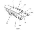
図4から図18に示すように、本開示の高い沿面距離を有する超小型リレーは、ハウジング1、台座部分2及び可動接点ばねとアーマチュアの組み合わせ3を含む。前記台座部分2はコイル26、鉄心21、固定接点ばね、コイル端子22及び第一プラスチック体23を含み、第一プラスチック体23は射出成形方式によってコイル26、鉄心21、固定接点ばね、コイル端子22を一体部材に集積し、且つ第一プラスチック体23はコイル26を完全に被覆し、コイル26はボビン及びエナメル線を含み、本実施例において、コイル26の軸線は水平に設置され、鉄心21の両端の極面211はそれぞれ第一プラスチック体23内から突出して第一プラスチック体23の上端までに延在され、且つそれぞれ第一プラスチック体23の両端に位置し、コイル端子22は2つであり、2つのコイル端子22はそれぞれ第一プラスチック体23の一端に位置し、即ちコイル端子22の第一プラスチック体から露出する部分は第一プラスチック体の一端に位置し、コイル端子22の第一プラスチック体から露出する部分はコイル引出端子221を含み、コイル端子22のコイル引出端子221はほぼ第一プラスチック体23の一端の角部位置に位置し、第一プラスチック体23は台座を含む。前記可動接点ばねとアーマチュアの組み合わせ3は二組の可動接点ばね片31、一つのアーマチュア32及び第二プラスチック体33を含み、第二プラスチック体33は射出成形方式によって二組の可動接点ばね片31、アーマチュア32を一体部材に集積し、ここで、コイル軸線方向に沿って、アーマチュア32は中間にあり、二組の可動接点ばね片31はそれぞれアーマチュア32の両側にある。前記可動接点ばねとアーマチュアの組み合わせ3の中間位置の両側にそれぞれ溶接ラグ構造311が設けられ、可動接点ばねとアーマチュアの組み合わせ3の溶接ラグ構造311は台座部分2の頂端の中間位置に取り付けられ、且つ可動接点ばねとアーマチュアの組み合わせ3における第二プラスチック体33から露出するアーマチュア32の両端はそれぞれ鉄心21の両端の極面211に対応して協力する。前記台座部分2において、第一プラスチック体23に射出成形された固定接点ばねは常開固定接点ばね片24及び溶接台25のみを含み、常閉固定接点ばね片を含まず、常開固定接点ばね片24は第一プラスチック体23の他端の位置に位置し、溶接台25は第一プラスチック体23の中央位置に対応し、且つ少なくとも可動接点ばねとアーマチュアの組み合わせ3の溶接ラグ構造311を支持することに用いられ、常閉固定接点ばね片を除去することによってコイル端子と固定接点ばねとの間の第一プラスチック体の外部における沿面距離を向上させる。本実施例において、鉄心はU型形状である。
4 to 18, the micro relay with high creepage distance disclosed herein includes a
本実施例において、前記溶接ラグ構造311は可動接点ばね片31に一体に設けられ且つ第二プラスチック体33の外に露出する。前記可動接点ばね片31は溶接ラグ構造に対して非対称構造であり、可動接点ばね片31の常開固定接点ばねに対応する一側に第二プラスチック体の外に露出する常開側312が設けられ、可動接点ばねの常開側312に常開可動接点313が取り付けられ、可動接点ばね片31の常開側に対応する他側は第二プラスチック体33内に完全に被覆される。
In this embodiment, the welded
本開示は、シーソー型リレーの常閉固定接点ばね及び可動接点ばねの常閉側を除去することにより、常開型シーソー型リレーとなる。 This disclosure removes the normally closed fixed contact spring and the normally closed side of the movable contact spring of a seesaw relay, resulting in a normally open seesaw relay.
本実施例において、第一プラスチック体23の水平断面は矩形又は矩形に近い形状を呈し、前記第一プラスチック体23における矩形の長辺に対応する側壁即ちコイル軸線に平行な側壁231には、コイル端子22の第一プラスチック体から露出する部分と第一プラスチック体23から露出する溶接台25との間に対応する沿面距離に第一凹溝232が設けられ、第一凹溝232を利用してコイル端子22の第一プラスチック体から露出する部分と溶接台5との間の沿面距離を増加させる。
In this embodiment, the horizontal cross section of the first
本実施例において、第一プラスチック体23の矩形の長辺に対応する側壁231には、前記第一プラスチック体23の一端に近接する頂端にさらに第一障壁235が上向きに突出して延設され、それによりコイル端子22の第一プラスチック体から露出する部分から鉄心21を通って常開端接点までの間の沿面経路が第一プラスチック体23の矩形の短辺に対応する側壁233に沿ってクリープする。
In this embodiment, a
本実施例において、前記第一プラスチック体23において、第一プラスチック体23の矩形の短辺に対応する側壁即ちコイル軸線に垂直な側壁233には、コイル端子22の第一プラスチック体から露出する部分と鉄心21の一端との間に対応する沿面経路第二凹溝234が設けられ、第二凹溝234を利用してコイル端子22の第一プラスチック体から露出する部分から鉄心を通って常開端接点までの間の沿面距離を増加させる。
本実施例において、前記第一プラスチック体23の上端には、鉄心21の他端と常開端接点との間に対応する沿面経路に第二障壁236がさらに設けられ、前記第二障壁236を利用してコイル端子22の第一プラスチック体から露出する部分から鉄心を通って常開端接点までの間の沿面距離をさらに増加させる。
In this embodiment, in the first
In this embodiment, a
本実施例において、前記可動接点ばねとアーマチュアの組み合わせ3はさらに永久磁石34を含み、前記永久磁石34はアーマチュアの長手方向即ちコイルの軸線方向に沿って分布し、且つ前記アーマチュア32と積層され、且つ永久磁石34は第一プラスチック体の他端のこの片側方向に向かってオフセットされ、実際には、可動接点ばね片31の常開側312のこの片側方向に向かってオフセットされる。つまり、永久磁石34の中間線はアーマチュア32の中間線に対してオフセット状態を呈し、且つ磁気回路の常開端にオフセットする。
In this embodiment, the
本実施例において、前記二組の可動接点ばね片31において、常開側に対応する他側の間はさらに接続シート35によって電気的に接続され、且つ前記接続シート35は前記第二プラスチック体33内に完全に被覆される。接続シートは二組の可動接点ばね片31の常開側に対応する他側の間に一体成形されてもよく、この時の二組の可動接点ばね片31は同一の部品であり、ほぼU字形である。接続シートは単独の部品であってもよく、接続シートの両端は溶接方式によって二組の可動接点ばね片31の常開側に対応する他側に固定され、又は接続シートの両端は二組の可動接点ばね片31の常開側に対応する他側に掛けられ且つ射出成形され、それにより接続シートの両端がそれぞれ二組の可動接点ばね片31に密着することを実現する。
In this embodiment, the two sets of movable
本実施例において、前記接続シート35は第二プラスチック体33の対応端の端部位置に近接し、それにより永久磁石34に十分な配置空間を提供する。
In this embodiment, the connecting
本実施例のリレーは一組の常開型リレーである。 The relays in this embodiment are a pair of normally open relays.
本開示の高い沿面距離を有する超小型リレーは、台座部分2において、第一プラスチック体23に射出成形された固定接点ばねが常開固定接点ばね片24及び溶接台25のみを含み、常閉固定接点ばね片を含まず、常開固定接点ばね片24が第一プラスチック体のコイル軸線に対応する他端に位置し、溶接台25がコイル軸線の中央位置に対応し、且つ少なくとも可動接点ばねとアーマチュアの組み合わせの溶接ラグ構造を支持することに用いられる。本開示のこのような構造は、台座部分2における常閉固定接点ばね片を除去することによってコイル端子22と固定接点ばねとの間の沿面距離を向上させることができ、リレーの体積を増加させない前提で、コイルと接点との間の沿面距離を効果的に向上させることを実現し、それにより新エネルギー、車載等の分野におけるリレーの入力及び出力に対してますます高くなる絶縁要件を満たす。
In the ultra-compact relay with a high creepage distance disclosed herein, the fixed contact spring injection-molded in the first
本開示の高い沿面距離を有する超小型リレーは、第一プラスチック体23において、リレーの入力及び出力(即ち、コイルと接点との間)のコイル端子と溶接台との間に対応する沿面経路に第一凹溝232が設けられ、それによりコイルと接点との間の沿面距離をさらに向上させることができる。本開示は第一プラスチック体23中において、リレーの入力及び出力(即ち、コイルと接点との間)のコイル端子に対応して鉄心21と常開端接点との間のこの沿面経路にさらに第二凹溝234と第二障壁236が設けられ、且つ第一障壁235を利用して、沿面経路を第一プラスチック体の矩形の長辺に対応する側壁231から第一プラスチック体の矩形の短辺に対応する側壁233クリープに沿ってクリープさせ、それによりコイルと接点との間の沿面距離をさらに向上させることができる。図5、図6及び図8に示すように、コイル端子と常開端接点との間の沿面距離は二本あり、一本の沿面距離はコイル端子22の第一プラスチック体から露出する部分から溶接台25まで(溶接台が常開端接点に直接連通するため)であり、当該沿面距離の沿面距離Sはコイル端子22の第一プラスチック体から露出する部分から溶接台25までであり、他の一本の沿面距離はコイル端子22の第一プラスチック体から露出する部分から鉄心を経て常開端接点までであり、当該沿面経路の沿面距離はコイル端子22の第一プラスチック体から露出する部分から鉄心21の一端までの距離D1と鉄心21の他端から常開端接点までの距離D2との和であり、二本の沿面距離のうち、沿面距離が短い方が、リレーのコイルと接点との間の沿面距離となる。
In the micro relay with a high creepage distance disclosed herein, a
本開示の高い沿面距離を有する超小型リレーは、永久磁石34がアーマチュアの長手方向即ちコイルの軸線方向に沿って分布し、且つ前記アーマチュア32と積層され、且つ永久磁石34は第一プラスチック体の他端の片側方向に向かってオフセットし、即ち可動接点ばね片の常開側の片側方向に向かってオフセットする。図14から図16に示すように、本開示のこのような構造は、非平衡型の二重磁気回路構造を用いることにより、常開端により大きな偏向力を持たせ、シーソー型リレーの常閉接点圧力がないためにリレーが駆動しにくく又は駆動しにくい等の現象の発生を回避し、リレーを確実に動作させることができる。図15に示すようにリレーが初期状態にある場合、この時に永久磁石の磁力と可動接点ばねの弾性反力は同じ方向であり、アーマチュア復元力=永久磁石の磁力+可動接点ばねの弾性反力である。従来技術の構造では、常閉接点のオーバーランによる接点圧力が発生し、即ちアーマチュア復元力=永久磁石の磁力+可動接点ばねの弾性反力-常閉接点圧力である。図16に示すように、リレーは動作状態(常開接点が閉じる)にあり、この時にリレーはコイル吸引力を受け、永久磁石の磁力と可動接点ばねの弾性反力は逆方向であり、この時にアーマチュア復元力=コイルの電磁吸引力+永久磁石の磁力-可動接点ばねの反力-接点圧力である。
In the micro relay with a high creepage distance disclosed herein, the
本開示の高い沿面距離を有する超小型リレーは、第一プラスチック体の共通端に対応する位置に可動接点ばねとアーマチュアの組み合わせを支持するための溶接ラグ構造の溶接台25のみが設けられて引出端子が設けられず、且つ二組の可動接点ばね片31の常開側に対応する他側の間が接続シート35によって一体に接続され、且つ接続シート35を第二プラスチック体33の対応端の端部位置に接近させることにより、永久磁石に十分な配置空間を提供する。本開示のこのような構造は、図18に示すように、接続シート35を介して二組の可動接点ばね片31を電気的に接続し、常開端接点の直列接続を実現し、接点隙間は従来技術のリレーの接点隙間の二倍であり、接点の隙間、接点を切断する耐圧及び製品の切断能力を効果的に向上させることができ、このように、外部の直列接続を必要とせず、接点隙間の耐圧及び接点隙間を切断する距離を満たすことができる。
The ultra-compact relay with a high creepage distance disclosed herein is provided with only a welding table 25 with a welded lug structure for supporting the combination of the movable contact spring and the armature at a position corresponding to the common end of the first plastic body, and no lead-out terminal is provided, and the other side corresponding to the normally open side of the two sets of movable
実施例2
図19から図21に示すように、本開示の高い沿面距離を有する超小型リレーは、実施例1との相違点は以下の通りである。前記固定接点ばねにおいて、溶接台25にさらに第一プラスチック体23から露出する共通端引出端子251が下向きに設けられ、前記共通端引出端子251は第一プラスチック体23の他端の方向に向かってオフセットされる。それにより本実施例のリレーは二組の常開型リレーとなる。
Example 2
19 to 21, the micro relay with a high creepage distance of the present disclosure is different from the first embodiment in the following points: In the fixed contact spring, the
以上は本開示の好適な実施例に過ぎず、本開示をいかなる形式で制限するものではない。本開示は好適な実施例によって以上のように開示したが、本開示を限定するものではない。当業者であれば、本開示の技術的解決手段の範囲から逸脱することなく、上記開示された技術的内容を利用して本開示の技術的解決手段に対して多くの可能な変更及び修飾を行うことができ、または同等の等価実施例に修正することができる。したがって、本開示の技術的解決手段の内容から逸脱せずに、本開示の技術の本質に基づいて以上の実施例に対して行われた任意の簡単な修正、同等の変化及び修飾は、いずれも本開示の技術的解決手段の保護範囲内に含まれるべきである。
The above are only preferred embodiments of the present disclosure, and do not limit the present disclosure in any manner. The present disclosure has been disclosed above by preferred embodiments, but does not limit the present disclosure. Those skilled in the art can make many possible changes and modifications to the technical solutions of the present disclosure using the technical content disclosed above without departing from the scope of the technical solutions of the present disclosure, or can modify them into equivalent equivalent embodiments. Therefore, any simple modifications, equivalent changes and modifications made to the above embodiments based on the essence of the technology of the present disclosure without departing from the content of the technical solutions of the present disclosure should all be included in the protection scope of the technical solutions of the present disclosure.
Claims (11)
前記第一プラスチック体に射出成形された前記固定接点ばねは常開固定接点ばね片及び溶接台のみを含み、常閉固定接点ばね片を含まず、前記常開固定接点ばね片は前記第一プラスチック体の他端に設置され、前記溶接台は前記第一プラスチック体の中間位置に対応して設置され、且つ少なくとも前記可動接点ばねとアーマチュアの組み合わせの前記溶接ラグ構造を支持することに用いられ、常閉固定接点ばね片を除去することによって前記コイル端子と前記固定接点ばねとの間の前記第一プラスチック体の外部における沿面距離を向上させる
ことを特徴とする高い沿面距離を有する超小型リレー。 A microminiature relay with a high creepage distance, comprising a base portion and a combination of a movable contact spring and an armature, the base portion comprising a coil, an iron core, a fixed contact spring, a coil terminal and a first plastic body, the first plastic body being formed by injection molding to integrate the coil, the iron core, the fixed contact spring and the coil terminal into a single piece, the first plastic body completely covering the coil, the pole faces at both ends of the iron core protruding from the first plastic body respectively and extending to an upper end of the first plastic body, and being located at both ends of the first plastic body respectively, the coil terminals being exposed from the first plastic body are formed in the first plastic body and the pole faces at both ends of the first plastic body are formed in the first plastic body and extend to an upper end of the first plastic body, the pole faces at both ends of the first plastic body protruding from the first plastic body respectively and extending ... a movable contact spring and armature assembly including two sets of movable contact spring pieces, an armature and a second plastic body, the second plastic body being formed by injection molding to integrate the two sets of movable contact spring pieces and the armature into a one-piece member, a welding lug structure being provided at a middle position of the movable contact spring and armature assembly, the movable contact spring and armature assembly being attached to a middle position of a top end of the base portion by the welding lug structure, and both ends of the armature exposed from the second plastic body being engaged with corresponding pole faces of both ends of the iron core,
a fixed contact spring injection molded into the first plastic body includes only a normally-open fixed contact spring piece and a welding base, and does not include a normally-closed fixed contact spring piece, the normally-open fixed contact spring piece is located at the other end of the first plastic body, the welding base is located corresponding to an intermediate position of the first plastic body, and is used to support at least the welding lug structure of the combination of the movable contact spring and the armature, and the creepage distance outside the first plastic body between the coil terminal and the fixed contact spring is improved by removing the normally-closed fixed contact spring piece.
ことを特徴とする請求項1に記載の高い沿面距離を有する超小型リレー。 2. The microminiature relay having a large creepage distance according to claim 1, wherein the axis of the coil is horizontally disposed, and the iron core is U-shaped.
ことを特徴とする請求項1又は2に記載の高い沿面距離を有する超小型リレー。 3. The micro relay with a high creepage distance as claimed in claim 1 or 2, characterized in that the welding lug structure is provided on both sides of the intermediate position of the combination of the movable contact spring and the armature, the two welding lug structures are respectively integrally formed with a corresponding set of the movable contact spring pieces and exposed outside the second plastic body, the movable contact spring pieces have an asymmetric structure with respect to the welding lug structure, one side of the movable contact spring piece corresponding to the normally open fixed contact spring piece is provided with a normally open side exposed outside the second plastic body, and a normally open movable contact is attached to the normally open side of the movable contact spring piece, and the other side corresponding to the normally open side of the movable contact spring piece is completely covered within the second plastic body.
ことを特徴とする請求項1に記載の高い沿面距離を有する超小型リレー。 The micro relay with a large creepage distance as described in claim 1, characterized in that the horizontal cross section of the first plastic body has a rectangular or nearly rectangular shape, and a first groove is provided in a side wall corresponding to the long side of the rectangle of the first plastic body, on a creepage path corresponding to between a portion of the coil terminal exposed from the first plastic body and a welding base exposed from the first plastic body, and the first groove is used to increase the creepage distance between the portion of the coil terminal exposed from the first plastic body and the welding base.
ことを特徴とする請求項1に記載の高い沿面距離を有する超小型リレー。 2. A micro-miniature relay having a large creepage distance as described in claim 1, characterized in that the horizontal cross section of the first plastic body has a rectangular or nearly rectangular shape, and a first barrier is further provided at a top end adjacent to one end of the first plastic body on a side wall corresponding to a long side of the rectangle of the first plastic body, and a first barrier is further provided to protrude upward and extend from the top end adjacent to one end of the first plastic body, thereby causing a creepage path from a portion of the coil terminal exposed from the first plastic body through the iron core to the normally open end contact to creep along the side wall corresponding to the short side of the rectangle of the first plastic body.
ことを特徴とする請求項5に記載の高い沿面距離を有する超小型リレー。 The ultra-miniature relay with a large creepage distance as described in claim 5, characterized in that a second groove is provided in a side wall corresponding to a short side of the rectangle of the first plastic body, in a creepage path corresponding to between a portion of the coil terminal exposed from the first plastic body and one end of the iron core, and the second groove is used to increase the creepage distance from the portion of the coil terminal exposed from the first plastic body through the iron core to the normally open end contact.
ことを特徴とする請求項6に記載の高い沿面距離を有する超小型リレー。 7. The micro relay having a large creepage distance as described in claim 6, characterized in that a second barrier is further provided at an upper end of the first plastic body in a corresponding creepage path between the other end of the core and the normally open end contact, and the second barrier is used to further increase the creepage distance from the portion of the coil terminal exposed from the first plastic body through the core to the normally open end contact.
ことを特徴とする請求項3に記載の高い沿面距離を有する超小型リレー。 4. The microminiature relay with high creepage distance as claimed in claim 3, characterized in that the combination of the movable contact spring and the armature further includes a permanent magnet, the permanent magnet being distributed along the longitudinal direction of the armature and stacked with the armature, and the permanent magnet being offset toward the other end of the first plastic body.
ことを特徴とする請求項8に記載の高い沿面距離を有する超小型リレー。 The micro relay having a large creepage distance as described in claim 8, characterized in that the fixed contact spring further has a common end lead terminal exposed from the first plastic body on the welding base facing downward, and the common end lead terminal is offset toward the other end of the first plastic body.
ことを特徴とする請求項8に記載の高い沿面距離を有する超小型リレー。 The ultra-miniature relay with a high creepage distance as described in claim 8, characterized in that the other side of the two sets of movable contact springs corresponding to the normally open side is further electrically connected by a connecting sheet, and the connecting sheet is completely covered by the second plastic body, and the connecting sheet is integrally connected to the two sets of movable contact spring pieces by an integral molding method, or the connecting sheet is a separate part, and both ends of the connecting sheet are abutted or welded to the two sets of movable contact spring pieces, respectively.
ことを特徴とする請求項10に記載の高い沿面距離を有する超小型リレー。 The microminiature relay with high creepage distance as claimed in claim 10, characterized in that the connecting sheet is adjacent to an end position of the corresponding end of the second plastic body, thereby providing sufficient arrangement space for the permanent magnet.
Applications Claiming Priority (3)
| Application Number | Priority Date | Filing Date | Title |
|---|---|---|---|
| CN202011609586.3 | 2020-12-30 | ||
| CN202011609586.3A CN112863945B (en) | 2020-12-30 | 2020-12-30 | An ultra-small relay with high creepage distance |
| PCT/CN2021/140179 WO2022143308A1 (en) | 2020-12-30 | 2021-12-21 | Microminiature relay having high creepage distance |
Publications (2)
| Publication Number | Publication Date |
|---|---|
| JP2023546233A JP2023546233A (en) | 2023-11-01 |
| JP7615519B2 true JP7615519B2 (en) | 2025-01-17 |
Family
ID=75998564
Family Applications (1)
| Application Number | Title | Priority Date | Filing Date |
|---|---|---|---|
| JP2023524334A Active JP7615519B2 (en) | 2020-12-30 | 2021-12-21 | Ultra-compact relay with high creepage distance |
Country Status (4)
| Country | Link |
|---|---|
| JP (1) | JP7615519B2 (en) |
| CN (1) | CN112863945B (en) |
| DE (1) | DE112021006720T5 (en) |
| WO (1) | WO2022143308A1 (en) |
Families Citing this family (12)
| Publication number | Priority date | Publication date | Assignee | Title |
|---|---|---|---|---|
| CN112863945B (en) * | 2020-12-30 | 2025-09-12 | 厦门宏发信号电子有限公司 | An ultra-small relay with high creepage distance |
| CN116417291A (en) * | 2021-12-30 | 2023-07-11 | 厦门宏发信号电子有限公司 | A coil structure adapted to see-saw armature and its high-frequency relay |
| CN114792612A (en) * | 2022-06-07 | 2022-07-26 | 浙江赛格玛电器有限公司 | Relay with a movable contact |
| USD1062654S1 (en) | 2022-06-17 | 2025-02-18 | Xiamen Hongfa Electric Power Controls Co., Ltd. | Relay |
| USD1042363S1 (en) | 2022-06-17 | 2024-09-17 | Xiamen Hongfa Electric Power Controls Co., Ltd. | Relay |
| USD1042364S1 (en) | 2022-06-17 | 2024-09-17 | Xiamen Hongfa Electric Power Controls Co., Ltd. | Relay |
| CN115458373B (en) * | 2022-09-30 | 2026-02-27 | 厦门宏发信号电子有限公司 | An ultra-miniature relay |
| CN115547751A (en) * | 2022-09-30 | 2022-12-30 | 厦门宏发信号电子有限公司 | Relays with high operating reliability |
| CN116031107A (en) * | 2023-01-06 | 2023-04-28 | 厦门宏发信号电子有限公司 | A high withstand voltage electromagnetic relay |
| CN118366822A (en) * | 2023-01-18 | 2024-07-19 | 厦门宏发汽车电子有限公司 | A snap-on electromagnetic relay |
| CN116168979A (en) * | 2023-03-31 | 2023-05-26 | 厦门宏发信号电子有限公司 | A magnetic steel reaction force mechanism of a relay and its electromagnetic relay |
| JP2026049489A (en) * | 2024-09-06 | 2026-03-18 | Fclコンポーネント株式会社 | relay |
Citations (1)
| Publication number | Priority date | Publication date | Assignee | Title |
|---|---|---|---|---|
| JP2001273846A (en) | 2000-03-28 | 2001-10-05 | Matsushita Electric Works Ltd | Electromagnetic relay |
Family Cites Families (9)
| Publication number | Priority date | Publication date | Assignee | Title |
|---|---|---|---|---|
| DE19727863C1 (en) * | 1997-06-30 | 1999-01-21 | Siemens Ag | Electromagnetic relay |
| CN2836224Y (en) * | 2005-05-19 | 2006-11-08 | 厦门宏发电声有限公司 | Electromagnetic relay armature component |
| JP6664978B2 (en) * | 2016-01-29 | 2020-03-13 | 富士通コンポーネント株式会社 | Electromagnetic relay |
| CN107342188A (en) * | 2016-11-21 | 2017-11-10 | 宁波金海电子有限公司 | A kind of relay of bobbin and base integrated through injection molding structure |
| CN108305818B (en) * | 2017-01-11 | 2019-06-14 | 厦门宏发电声股份有限公司 | A kind of high-power relay with high insulating property of solar photovoltaic inverter |
| CN109545627B (en) * | 2018-10-31 | 2024-06-18 | 厦门宏发信号电子有限公司 | Relay structure capable of improving gap of breaking contact |
| CN112038178A (en) * | 2020-08-19 | 2020-12-04 | 漳州宏发电声有限公司 | Electromagnetic relay capable of increasing creepage distance |
| CN214043550U (en) * | 2020-12-30 | 2021-08-24 | 厦门宏发信号电子有限公司 | Ultra-small relays with high creepage distances |
| CN112863945B (en) * | 2020-12-30 | 2025-09-12 | 厦门宏发信号电子有限公司 | An ultra-small relay with high creepage distance |
-
2020
- 2020-12-30 CN CN202011609586.3A patent/CN112863945B/en active Active
-
2021
- 2021-12-21 DE DE112021006720.6T patent/DE112021006720T5/en active Pending
- 2021-12-21 JP JP2023524334A patent/JP7615519B2/en active Active
- 2021-12-21 WO PCT/CN2021/140179 patent/WO2022143308A1/en not_active Ceased
Patent Citations (1)
| Publication number | Priority date | Publication date | Assignee | Title |
|---|---|---|---|---|
| JP2001273846A (en) | 2000-03-28 | 2001-10-05 | Matsushita Electric Works Ltd | Electromagnetic relay |
Also Published As
| Publication number | Publication date |
|---|---|
| WO2022143308A1 (en) | 2022-07-07 |
| DE112021006720T5 (en) | 2023-10-12 |
| JP2023546233A (en) | 2023-11-01 |
| CN112863945A (en) | 2021-05-28 |
| CN112863945B (en) | 2025-09-12 |
Similar Documents
| Publication | Publication Date | Title |
|---|---|---|
| JP7615519B2 (en) | Ultra-compact relay with high creepage distance | |
| US9378914B2 (en) | Contact device and electromagnetic contactor using the same | |
| JP4190379B2 (en) | Combined electromagnetic relay | |
| CN102915880B (en) | Electromagnetic relay | |
| US9437382B2 (en) | Electromagnet device and electromagnetic relay using the same | |
| KR20130062332A (en) | Contact mechanism and electromagnetic contactor using same | |
| CN103367049B (en) | Polarized electromagnetic relay | |
| CN116438618A (en) | Contact devices and electromagnetic relays | |
| CN112038178A (en) | Electromagnetic relay capable of increasing creepage distance | |
| US12261005B2 (en) | Electromagnetic relay and electromagnetic device | |
| CN117352333A (en) | Electromagnetic relay | |
| JP2026501415A (en) | High-voltage electromagnetic relay | |
| CN214043550U (en) | Ultra-small relays with high creepage distances | |
| CN222051646U (en) | Contact unit, electric control part and relay | |
| CN221977837U (en) | Moving part, magnetic latching relay and ammeter | |
| JP7357193B2 (en) | electromagnetic relay | |
| WO2025138425A1 (en) | Relay | |
| CN118039413A (en) | A moving part, magnetic latching relay and electric meter | |
| CN218039034U (en) | Magnetic latching relay | |
| CN114496661B (en) | Microminiature electromagnetic relay with high-voltage breaking capacity | |
| CN204905165U (en) | Move spring armature part and clap box -like electromagnetic relay thereof | |
| US4482875A (en) | Polarized electromagnetic midget relay | |
| CN111261465B (en) | An impact-resistant electromagnetic relay | |
| CN115812243A (en) | Enclosed Electromagnetic Contactor | |
| CN219842931U (en) | Relay for increasing creepage distance |
Legal Events
| Date | Code | Title | Description |
|---|---|---|---|
| A621 | Written request for application examination |
Free format text: JAPANESE INTERMEDIATE CODE: A621 Effective date: 20230420 |
|
| A977 | Report on retrieval |
Free format text: JAPANESE INTERMEDIATE CODE: A971007 Effective date: 20240508 |
|
| A131 | Notification of reasons for refusal |
Free format text: JAPANESE INTERMEDIATE CODE: A131 Effective date: 20240514 |
|
| A521 | Request for written amendment filed |
Free format text: JAPANESE INTERMEDIATE CODE: A523 Effective date: 20240809 |
|
| TRDD | Decision of grant or rejection written | ||
| A01 | Written decision to grant a patent or to grant a registration (utility model) |
Free format text: JAPANESE INTERMEDIATE CODE: A01 Effective date: 20241203 |
|
| A61 | First payment of annual fees (during grant procedure) |
Free format text: JAPANESE INTERMEDIATE CODE: A61 Effective date: 20241213 |
|
| R150 | Certificate of patent or registration of utility model |
Ref document number: 7615519 Country of ref document: JP Free format text: JAPANESE INTERMEDIATE CODE: R150 |