JP7616372B2 - Vehicle display system, vehicle display method, and vehicle display program - Google Patents
Vehicle display system, vehicle display method, and vehicle display program Download PDFInfo
- Publication number
- JP7616372B2 JP7616372B2 JP2023525891A JP2023525891A JP7616372B2 JP 7616372 B2 JP7616372 B2 JP 7616372B2 JP 2023525891 A JP2023525891 A JP 2023525891A JP 2023525891 A JP2023525891 A JP 2023525891A JP 7616372 B2 JP7616372 B2 JP 7616372B2
- Authority
- JP
- Japan
- Prior art keywords
- vehicle
- display
- content
- processing unit
- related content
- Prior art date
- Legal status (The legal status is an assumption and is not a legal conclusion. Google has not performed a legal analysis and makes no representation as to the accuracy of the status listed.)
- Active
Links
Images







Classifications
-
- B—PERFORMING OPERATIONS; TRANSPORTING
- B60—VEHICLES IN GENERAL
- B60K—ARRANGEMENT OR MOUNTING OF PROPULSION UNITS OR OF TRANSMISSIONS IN VEHICLES; ARRANGEMENT OR MOUNTING OF PLURAL DIVERSE PRIME-MOVERS IN VEHICLES; AUXILIARY DRIVES FOR VEHICLES; INSTRUMENTATION OR DASHBOARDS FOR VEHICLES; ARRANGEMENTS IN CONNECTION WITH COOLING, AIR INTAKE, GAS EXHAUST OR FUEL SUPPLY OF PROPULSION UNITS IN VEHICLES
- B60K35/00—Instruments specially adapted for vehicles; Arrangement of instruments in or on vehicles
- B60K35/80—Arrangements for controlling instruments
- B60K35/81—Arrangements for controlling instruments for controlling displays
-
- B—PERFORMING OPERATIONS; TRANSPORTING
- B60—VEHICLES IN GENERAL
- B60K—ARRANGEMENT OR MOUNTING OF PROPULSION UNITS OR OF TRANSMISSIONS IN VEHICLES; ARRANGEMENT OR MOUNTING OF PLURAL DIVERSE PRIME-MOVERS IN VEHICLES; AUXILIARY DRIVES FOR VEHICLES; INSTRUMENTATION OR DASHBOARDS FOR VEHICLES; ARRANGEMENTS IN CONNECTION WITH COOLING, AIR INTAKE, GAS EXHAUST OR FUEL SUPPLY OF PROPULSION UNITS IN VEHICLES
- B60K35/00—Instruments specially adapted for vehicles; Arrangement of instruments in or on vehicles
- B60K35/10—Input arrangements, i.e. from user to vehicle, associated with vehicle functions or specially adapted therefor
-
- B—PERFORMING OPERATIONS; TRANSPORTING
- B60—VEHICLES IN GENERAL
- B60K—ARRANGEMENT OR MOUNTING OF PROPULSION UNITS OR OF TRANSMISSIONS IN VEHICLES; ARRANGEMENT OR MOUNTING OF PLURAL DIVERSE PRIME-MOVERS IN VEHICLES; AUXILIARY DRIVES FOR VEHICLES; INSTRUMENTATION OR DASHBOARDS FOR VEHICLES; ARRANGEMENTS IN CONNECTION WITH COOLING, AIR INTAKE, GAS EXHAUST OR FUEL SUPPLY OF PROPULSION UNITS IN VEHICLES
- B60K35/00—Instruments specially adapted for vehicles; Arrangement of instruments in or on vehicles
- B60K35/20—Output arrangements, i.e. from vehicle to user, associated with vehicle functions or specially adapted therefor
- B60K35/21—Output arrangements, i.e. from vehicle to user, associated with vehicle functions or specially adapted therefor using visual output, e.g. blinking lights or matrix displays
- B60K35/22—Display screens
-
- B—PERFORMING OPERATIONS; TRANSPORTING
- B60—VEHICLES IN GENERAL
- B60K—ARRANGEMENT OR MOUNTING OF PROPULSION UNITS OR OF TRANSMISSIONS IN VEHICLES; ARRANGEMENT OR MOUNTING OF PLURAL DIVERSE PRIME-MOVERS IN VEHICLES; AUXILIARY DRIVES FOR VEHICLES; INSTRUMENTATION OR DASHBOARDS FOR VEHICLES; ARRANGEMENTS IN CONNECTION WITH COOLING, AIR INTAKE, GAS EXHAUST OR FUEL SUPPLY OF PROPULSION UNITS IN VEHICLES
- B60K35/00—Instruments specially adapted for vehicles; Arrangement of instruments in or on vehicles
- B60K35/20—Output arrangements, i.e. from vehicle to user, associated with vehicle functions or specially adapted therefor
- B60K35/26—Output arrangements, i.e. from vehicle to user, associated with vehicle functions or specially adapted therefor using acoustic output
- B60K35/265—Voice
-
- B—PERFORMING OPERATIONS; TRANSPORTING
- B60—VEHICLES IN GENERAL
- B60K—ARRANGEMENT OR MOUNTING OF PROPULSION UNITS OR OF TRANSMISSIONS IN VEHICLES; ARRANGEMENT OR MOUNTING OF PLURAL DIVERSE PRIME-MOVERS IN VEHICLES; AUXILIARY DRIVES FOR VEHICLES; INSTRUMENTATION OR DASHBOARDS FOR VEHICLES; ARRANGEMENTS IN CONNECTION WITH COOLING, AIR INTAKE, GAS EXHAUST OR FUEL SUPPLY OF PROPULSION UNITS IN VEHICLES
- B60K35/00—Instruments specially adapted for vehicles; Arrangement of instruments in or on vehicles
- B60K35/20—Output arrangements, i.e. from vehicle to user, associated with vehicle functions or specially adapted therefor
- B60K35/28—Output arrangements, i.e. from vehicle to user, associated with vehicle functions or specially adapted therefor characterised by the type of the output information, e.g. video entertainment or vehicle dynamics information; characterised by the purpose of the output information, e.g. for attracting the attention of the driver
-
- G—PHYSICS
- G08—SIGNALLING
- G08G—TRAFFIC CONTROL SYSTEMS
- G08G1/00—Traffic control systems for road vehicles
- G08G1/16—Anti-collision systems
-
- G—PHYSICS
- G09—EDUCATION; CRYPTOGRAPHY; DISPLAY; ADVERTISING; SEALS
- G09G—ARRANGEMENTS OR CIRCUITS FOR CONTROL OF INDICATING DEVICES USING STATIC MEANS TO PRESENT VARIABLE INFORMATION
- G09G5/00—Control arrangements or circuits for visual indicators common to cathode-ray tube indicators and other visual indicators
-
- G—PHYSICS
- G09—EDUCATION; CRYPTOGRAPHY; DISPLAY; ADVERTISING; SEALS
- G09G—ARRANGEMENTS OR CIRCUITS FOR CONTROL OF INDICATING DEVICES USING STATIC MEANS TO PRESENT VARIABLE INFORMATION
- G09G5/00—Control arrangements or circuits for visual indicators common to cathode-ray tube indicators and other visual indicators
- G09G5/36—Control arrangements or circuits for visual indicators common to cathode-ray tube indicators and other visual indicators characterised by the display of a graphic pattern, e.g. using an all-points-addressable [APA] memory
- G09G5/38—Control arrangements or circuits for visual indicators common to cathode-ray tube indicators and other visual indicators characterised by the display of a graphic pattern, e.g. using an all-points-addressable [APA] memory with means for controlling the display position
-
- H—ELECTRICITY
- H04—ELECTRIC COMMUNICATION TECHNIQUE
- H04N—PICTORIAL COMMUNICATION, e.g. TELEVISION
- H04N7/00—Television systems
- H04N7/18—Closed-circuit television [CCTV] systems, i.e. systems in which the video signal is not broadcast
Landscapes
- Engineering & Computer Science (AREA)
- Chemical & Material Sciences (AREA)
- Combustion & Propulsion (AREA)
- Transportation (AREA)
- Mechanical Engineering (AREA)
- Physics & Mathematics (AREA)
- General Physics & Mathematics (AREA)
- Theoretical Computer Science (AREA)
- Computer Hardware Design (AREA)
- Multimedia (AREA)
- Signal Processing (AREA)
- Fittings On The Vehicle Exterior For Carrying Loads, And Devices For Holding Or Mounting Articles (AREA)
- Controls And Circuits For Display Device (AREA)
- User Interface Of Digital Computer (AREA)
- Traffic Control Systems (AREA)
- Control Of Driving Devices And Active Controlling Of Vehicle (AREA)
- Instrument Panels (AREA)
- Position Input By Displaying (AREA)
Description
本出願は、2021年6月2日に出願された日本出願番号2021-092992号に基づくもので、ここにその記載内容を援用する。 This application is based on Japanese Application No. 2021-092992, filed on June 2, 2021, the contents of which are incorporated herein by reference.
本開示は、車両用表示システム、車両用表示方法、及び車両用表示プログラムに関する。 The present disclosure relates to a vehicle display system, a vehicle display method, and a vehicle display program.
運転に必要な視覚情報を補うため、周辺カメラを使用した周辺監視機能が多数提案されている。例えば特許文献1参照。特許文献1記載の技術では、後方と側面の周辺カメラの撮像画像を連続した合成画像に加工することで、複数の画像を1枚のように見せている。また、ウィンカにより曲がる方向を理解し、曲がる方向の画角を広げることで周辺監視をしやすくした電子ミラー技術も提供されている。 Many peripheral monitoring functions using peripheral cameras have been proposed to supplement the visual information required for driving. For example, see Patent Document 1. In the technology described in Patent Document 1, images captured by peripheral cameras at the rear and sides are processed into a continuous composite image, making multiple images appear as a single image. Electronic mirror technology has also been provided that makes it easier to monitor the surroundings by understanding the direction of turning using blinkers and widening the angle of view in the direction of turning.
このように、複数画像を連続した一つの画像に加工したり、カメラ側で機械的に画角を変更したりすることで、乗員が確認している場所を概ね変更することなく、本来確認させるべき画像を視認させることができる。これらの課題は、表示器の表示面積を大きくしながらフレーミングすることでも解決できるが、フレーミング技術だけでは車両乗員が求める情報を提供できない。In this way, by processing multiple images into one continuous image or by mechanically changing the angle of view on the camera side, the occupants can see the image they are supposed to see without changing the location they are looking at. These issues can also be solved by framing the display while increasing the display area of the display, but framing technology alone cannot provide the information that vehicle occupants want.
また、各種センサ類から得られる情報をグラフィカルな視覚情報にすることで、見やすく分かりやすい情報に変更して運転をサポートする技術も提供されている。技術が向上するにつれて車両内で取り扱われる情報は増加し、ディスプレイの表示画面の面積とその設置個数は増加傾向にある。 There is also technology being offered that supports driving by converting information obtained from various sensors into graphical visual information that is easy to see and understand. As technology improves, the amount of information handled within vehicles increases, and the size of display screens and the number of displays installed are on the rise.
多くの情報が表示されていれば車両乗員をサポートできるが、乗員の視野範囲は限られているため全ての情報を一度に確認できない。そのため、車両乗員が視線を移動する回数が増加したり、首を振ったりする回数が増加し不便となる。また、多くの情報が表示されていると、必要且つ適切な情報をわずかな時間で探索し一目で確認することも困難である。 Although a large amount of information can be displayed to support vehicle occupants, the occupants' field of vision is limited and they are unable to view all the information at once. This increases the number of times that vehicle occupants move their eyes or turn their heads, which is inconvenient. In addition, when a large amount of information is displayed, it is difficult to quickly search for and view the necessary and appropriate information at a glance.
本開示の目的は、乗員が視線を移動する回数や首を振る回数を極力抑制しながら適切な情報を確認できるようにした車両用表示システム、車両用表示方法及び車両用表示プログラムを提供することにある。 The object of the present disclosure is to provide a vehicle display system, a vehicle display method, and a vehicle display program that enable occupants to check appropriate information while minimizing the number of times they move their eyes or shake their heads.
本開示の一態様によれば、判定部は、車両乗員により見られている主コンテンツが地図画面であるか判定し、変化検知部は、車速センサにより検出された自車両の速度信号から自車両の走行速度が所定の時間内に急速に低下したことを判定し、地図画面に関連する関連コンテンツとしてバックカメラの撮像画像の状況変化を検知することで自車両の周辺に他車両が増加したと判定する。表示処理部は、変化検知部による検知結果に基づいてバックカメラの撮像画像の表示態様を変更し、地図画面及びバックカメラの撮像画像を車両乗員の視線の先の視野範囲に表示する。 According to one aspect of the present disclosure, the determination unit determines whether the primary content being viewed by the vehicle occupant is the map screen , the change detection unit determines that the vehicle's traveling speed has rapidly decreased within a predetermined time from the vehicle's speed signal detected by the vehicle speed sensor, and determines that the number of other vehicles has increased around the vehicle by detecting a change in the situation of the image captured by the backup camera as related content related to the map screen. The display processing unit changes the display mode of the image captured by the backup camera based on the detection result by the change detection unit, and displays the map screen and the image captured by the backup camera in the field of view ahead of the vehicle occupant's line of sight .
本開示の一態様によれば、変化検知部による検知結果に基づいて地図画面及びバックカメラの撮像画像を車両乗員の視線の先の視野範囲に表示しているため、車両乗員は地図画面と共にバックカメラの撮像画像も確認できる。このため、乗員が視線を移動する回数や首を振る回数を極力抑制しながら適切な情報を確認できる。
According to one aspect of the present disclosure, the map screen and the image captured by the backup camera are displayed in the field of view of the vehicle occupant's line of sight based on the detection result by the change detection unit, so that the vehicle occupant can check the image captured by the backup camera along with the map screen . This allows the occupant to check appropriate information while minimizing the number of times they move their line of sight or shake their head.
本開示についての上記目的およびその他の目的、特徴や利点は、添付の図面を参照しながら下記の詳細な記述により、より明確になる。その図面は、
以下、車両用表示システム1、車両用表示方法、車両用表示プログラムに係る幾つかの実施形態について図面を参照しながら説明する。なお、各実施形態において実質的に共通する部位には同一の符号を付して説明する。 Below, several embodiments of the vehicle display system 1, the vehicle display method, and the vehicle display program will be described with reference to the drawings. Note that parts that are essentially common to each embodiment will be described with the same reference numerals.
図1に示すように、車両用表示システム1は、センタディスプレイ3、及び電子ミラー4など複数の表示器を備えるコックピットシステムにより構成される。ただし、表示器の数や設置あるいは構成は一例であり、これらに限定されない。As shown in Figure 1, the vehicle display system 1 is composed of a cockpit system equipped with multiple displays, such as a
センタディスプレイ3は、例えば液晶ディスプレイや有機ELディスプレイにより構成され、運転席と助手席との間に設置されている。The
センタディスプレイ3は、ドライバや助手席の乗員の両者が視認しやすいセンタコンソール付近に設けられると共に各種のコンテンツを表示可能になっている。センタディスプレイ3の上には操作パネル21が構成されており、センタディスプレイ3に表示させるコンテンツの選択や空調操作、オーディオ操作、ナビゲーション機能の入力操作できるようになっている。The
電子ミラー4は、ドアミラーカメラ4a及びディスプレイ4bを用いて構成される。図2参照。ドアミラーカメラ4aは、自車両Caのドアミラーの設置箇所から自車両Caの後方、すなわち側後方を撮像する周辺カメラ23である。The
電子ミラー4のディスプレイ4bは、例えば液晶ディスプレイや有機ELディスプレイにより構成される。ディスプレイ4bは、ドライバの左右位置にそれぞれ一つずつ設置されるもので、例えば車室内のAピラーの下部にそれぞれ設置される。The
電子ミラー4のディスプレイ4bは、ドライバから車両側後方を確認しやすい位置に設けられ、ディスプレイ4bには、ドアミラーカメラ4aにより撮像された車両の周辺情報などを表示可能な構成となっている。The
また車両内には、図1及び図2に示すように、多数のECU5が構成されており、車内ネットワーク25に接続されている。ECU5は、表示系のECU、周辺監視系のECU、走行制御系のECU、車両外部と通信接続するDCMを含む。DCMは、Data Communication Moduleの略である。走行制御系のECUは、周知の車両制御ECU、エンジン制御ECU、モータ制御ECU、ブレーキ制御ECU、ステアリング制御ECU及び統合制御ECU等である。走行制御系のECUには自動運転ECUが含まれる。自動運転ECUは、Autonomous Driving Electric Control Unitである。
As shown in Figures 1 and 2,
自動運転ECUは、自動制御信号を入力すると、運転アクチュエータを駆動することで対応した所定のレベルの運転支援、自動運転を実行する。例えば、レベルIの運転支援では、障害物への衝突を避ける自動ブレーキ、前車に追従して走行する追従走行、又は、両脇の車線からはみ出さないように制御する走行レーンはみ出し防止走行、を実行できる。レベルIIの自動運転では、レベルIの運転支援の組み合わせ、又は、特定条件下での自動運転、例えば高速道路で遅い車両が存在すれば自動で追い越したり、高速道路の分合流を自動で行ったりする自動運転モードを実行できる。レベルIII以上の自動運転では、システムにより監視しながらシステムが全ての運転タスクを実行する。When the autonomous driving ECU receives an automatic control signal, it drives the driving actuator to perform a corresponding predetermined level of driving assistance or autonomous driving. For example, level I driving assistance can perform automatic braking to avoid collisions with obstacles, following driving to follow the vehicle in front, or lane prevention driving to prevent the vehicle from going out of the lanes on either side. Level II autonomous driving can perform a combination of level I driving assistance, or autonomous driving under specific conditions, such as an autonomous driving mode that automatically overtakes slower vehicles on a highway or automatically merges onto the highway. In autonomous driving at level III or higher, the system performs all driving tasks while monitoring the vehicle.
各ECU5は、プロセッサ、キャッシュメモリ、RAM、ROMなどの各種の記憶部6、I/O、これらを接続するバスを備えたマイクロコンピュータを主体として構成される。各ECU5は、車両内に設けられる他のECU5と通信制御部7及び車内ネットワーク25を通じて通信可能に接続されている。Each ECU 5 is mainly composed of a microcomputer equipped with various storage units 6 such as a processor, cache memory, RAM, ROM, I/O, and a bus connecting these. Each ECU 5 is communicatively connected to
本実施形態では、図2に示すように、複数の表示系のECU5が車両用装置10としてのHCUを構成しており、表示系のECU5の内部の物理リソースの処理能力を分担してセンタディスプレイ3及び電子ミラー4のディスプレイ4bに表示処理する。表示系のECU5は専用線で互いに接続しても良いし、1つのECU5により構成されていても良い。HCUは、Human Machine Interface Control Unitの略であり情報提示制御装置を示す。前述した記憶部6は、コンピュータによって読み取り可能なプログラム及びデータを非一時的に格納する非遷移的実体的記憶媒体を示す。非遷移的実体的記憶媒体は、半導体メモリなどにより実現される。In this embodiment, as shown in FIG. 2, multiple
図2に示すように、車両用装置10は、制御装置11、演算装置12、記憶部6、表示処理部13、音声処理部14、各種装置からの入力又は出力を管理するI/O制御部15、他のECU5との間で通信管理する通信制御部7、を備える。As shown in FIG. 2, the
また、図2に示した位置検出器19、操作パネル21、乗員モニタ22、周辺カメラ23、距離検出センサ24の出力信号についてはI/O制御部15を通じて入力する形態を説明するが、車内ネットワーク25を通じて、周辺監視系のECU、走行制御系のECUなどの他のECU5から信号入力されることもある。
In addition, the output signals of the
演算装置12は、制御装置11の制御に基づいて、記憶部6に記憶された画像、文章や文字など(以下、画像等と称する)のコンテンツについて、センタディスプレイ3、電子ミラー4のディスプレイ4bの表示画面に表示させる表示領域を演算し、画像等のコンテンツをセンタディスプレイ3、電子ミラー4のディスプレイ4bの表示画面の何れの領域に表示させるか、また、何れの領域に重ね合わせて表示させるか演算し、画像等のコンテンツと共に表示領域を制御装置11を通じて表示処理部13に出力する。Based on the control of the
表示処理部13は、制御装置11の制御に基づいて、センタディスプレイ3、電子ミラー4のディスプレイ4bの表示画面の中の前述の表示領域に画像等のコンテンツを表示処理する。これにより、各ディスプレイ3、4bの表示画面には、表示レイヤ毎に画像等のコンテンツを重ね合わせて表示できる。音声処理部14は、制御装置11の制御に基づいて、マイク17から入力された受話音声を入力すると共に、スピーカ18から送話音声を出力する。音声処理部14は、文章や文字のコンテンツを制御装置11から入力すると、音声に変換してスピーカ18を通じて読み上げて出力する。
The
位置検出器19は、図示しない周知のGPSなどのGNSS受信機、加速度センサやジャイロセンサなどの慣性センサを用いて高精度に位置を検出する。位置検出器19は、位置検出信号をI/O制御部15を通じて制御装置11に出力する。制御装置11の位置特定部11aは、地図データ入力器から入力される地図情報と位置検出器19の位置検出信号に基づいて車両の現在位置を高精度に逐次測位するADASロケータとしての機能を実現する。ADASは、Advanced Driver Assistance Systemsの略である。The
この場合、車両位置は、緯度及び経度からなる座標系で表され、この座標系では、例えば、X軸が経度、Y軸が緯度を示す。なお、車両位置の測位は、例えば、自車両Caに搭載されている車速センサを用いても良い。車速センサは、車両の速度を検出し速度信号を制御装置11に出力する。測位は車速センサによるセンシング結果に基づき求められる走行距離の情報などに基づいて行うなど、自車両Caの位置を特定できる構成であれば、種々の構成を採用できる。制御装置11は、自車両Caの現在位置に基づいて、いわゆるナビゲーション処理を行うことができる。In this case, the vehicle position is represented in a coordinate system consisting of latitude and longitude, where, for example, the X-axis indicates longitude and the Y-axis indicates latitude. The vehicle position may be measured using, for example, a vehicle speed sensor mounted on the host vehicle Ca. The vehicle speed sensor detects the vehicle speed and outputs a speed signal to the
操作パネル21は、センタディスプレイ3の上に構成されたタッチパネルであり、I/O制御部15は、乗員による操作入力があると操作入力を受け付け、制御装置11に出力する。制御装置11は操作パネル21の操作信号に基づいた制御を実行する。The
乗員モニタ22は、車両内に搭乗した乗員の状態又は操作状態を検知する。乗員モニタ22は、例えばパワースイッチ、乗員状態モニタ、ターンスイッチ、自動制御スイッチなどを用いて構成され、各種の信号を制御装置11に出力する。乗員モニタ22は、ドライバによりステアリングホイールが把持されているか又は操舵されているか否かを検出するステアリングセンサ、シートに着座しているか否かを検出する着座センサ、アクセルペダル又はブレーキペダルの踏込センサなどを含んでいても良い。The occupant monitor 22 detects the state or operation state of the occupant in the vehicle. The occupant monitor 22 is configured using, for example, a power switch, an occupant state monitor, a turn switch, an automatic control switch, etc., and outputs various signals to the
パワースイッチは、内燃機関又は電動モータを始動させるために車室内にて乗員によりオン操作されることで、当該操作に応じた信号を出力する。乗員状態モニタは、D席又はP席の乗員の状態を画像センサにより撮影することで当該乗員の状態を検知して撮像信号を出力するカメラを含んで構成される。ドライバの乗員状態モニタはDSMと称されている。DSMは、Driver Status Monitorの略である。乗員状態モニタは、ドライバの頭部に近赤外光を照射して撮影した撮像信号を取得し必要に応じて画像解析して制御装置11に出力する。When the power switch is turned on by an occupant in the vehicle cabin to start the internal combustion engine or electric motor, it outputs a signal corresponding to the operation. The occupant status monitor includes a camera that detects the status of an occupant in the D or P seat by photographing the status of the occupant with an image sensor and outputs an image signal. The driver's occupant status monitor is called a DSM. DSM is an abbreviation for Driver Status Monitor. The occupant status monitor shines near-infrared light on the driver's head to obtain an image signal, performs image analysis as necessary, and outputs the image to the
乗員状態モニタは、特に運転支援中や自動運転中にドライバなどの乗員の状態を検知するために使用される。ターンスイッチは、自車両Caの方向指示器を作動させるときに車室内にて乗員によりオン操作されることで、当該操作に応じて右方又は左方にターンするターン信号を出力する。The occupant status monitor is used to detect the status of occupants such as the driver, particularly during driving assistance or autonomous driving. The turn switch is turned on by an occupant in the vehicle cabin when activating the turn signal of the host vehicle Ca, and outputs a turn signal to turn right or left in response to the operation.
自動制御スイッチは、車両の走行状態に対する所定の運転支援又は自動制御を指令するために、車室内にて乗員によりオン操作されることで、当該操作に応じた自動制御信号を出力する。この自動制御信号は走行制御系のECUに出力されることで、対応した所定のレベルの運転支援又は自動運転制御を実行できる。When an occupant in the vehicle turns on the automatic control switch in order to command a specific driving assistance or automatic control for the vehicle's driving state, the automatic control switch outputs an automatic control signal corresponding to the operation. This automatic control signal is output to the ECU of the driving control system, thereby enabling the corresponding specific level of driving assistance or automatic driving control to be executed.
制御装置11は、乗員モニタ22のセンサ信号により車両乗員の挙動、例えば視線が何れの方向を向いているかを判定でき、また、パワースイッチの操作状態、方向指示器の作動状態、車両の自動制御の指令情報、車両の速度センサによる速度情報などを入力できる。The
周辺カメラ23は、車両の前方を撮像する前方視界カメラや、車両の後部を撮像するバックカメラ、車両の前側部や後側部を撮像するコーナカメラ、又は、車両の側部を撮像するサイドカメラ、電子ミラー4のドアミラーカメラ4aなどによるものであり、これらはそれぞれフロントガイドモニタ、バックガイドモニタ、コーナービューモニタ、サイドガイドモニタ、電子ミラー4の各撮像信号としてI/O制御部15を通じて制御装置11に出力され記憶部6に記憶される。The
電子ミラー4のディスプレイ4bは、ドアミラーカメラ4aにより撮像された映像を表示させる。なお電子ミラー4は、後写鏡を再現するものである。このため、電子ミラー4は、ドアミラーカメラ4aにより撮像された映像について鏡像反転させた映像を、電子ミラー4用のディスプレイ4bに表示させる。The
また車両には障害物との距離などを検出する距離検出センサ24が周辺監視センサとして設置されている。距離検出センサ24は、クリアランスソナー24a、LiDAR又はミリ波を用いたレーダなどにより構成され、車両前方、車両前側部、車両後側部、車両後方又は車両側部に近接する車両や人などの障害物との距離を検出する。The vehicle is also equipped with a
各ECU5にはSoCが搭載されている。SoCはSystem On Chipの略である。搭載されたSoCには前述したマイクロコンピュータが組込まれている。ECU5のSoCに組み込まれたマイクロコンピュータは、予めインストールされた汎用OS、リアルタイムOS上で各種の複数のアプリケーション(以下、アプリと略す)が動作するように構成されており、これにより制御装置11は後述する機能を実現できる。アプリは、画像処理アプリやその他のアプリを含む。画像処理アプリの描画要求に応じてSoCに組み込まれたプロセッサが、センタディスプレイ3、電子ミラー4のディスプレイ4bの表示画面に描画処理する。Each
また、アプリにより描画されるコンテンツは、他のディスプレイ、ここではセンタディスプレイ3にも表示できる。アプリにはナビアプリ等が含まれている。ナビアプリは、ナビゲーション機能を実現するものであると共に、主にセンタディスプレイ3又は電子ミラー4のディスプレイ4bに表示される地図画像や車両の現在位置などを含むナビゲーション画面を描画する。
Furthermore, the content rendered by the app can also be displayed on other displays, in this case the
またアプリには画像合成アプリも含まれている。画像合成アプリは、表示器に表示する様々な画像コンテンツの大きさや種類を特定し、画像コンテンツの画像を1フレーム内に合成し、この合成された混在画像をセンタディスプレイ3又は電子ミラー4のディスプレイ4bに出力するアプリである。画像合成アプリは、コンポジッタとも称される画像合成部としての機能や、また画像出力部としての機能を実現する。The apps also include an image synthesis app. The image synthesis app is an app that specifies the size and type of various image content to be displayed on the display, synthesizes the images of the image content within one frame, and outputs this synthesized mixed image to the
またアプリには検知アプリも含まれている。検知アプリは、乗員モニタ22による撮像信号に基づいて車両内の乗員の仕草を検知したり、手指による操作やその視線を検知したり、車両内の乗員の顔の表情や仕草を検知する。また、操作パネル21のタッチパネルの操作者を検知する。The apps also include a detection app. The detection app detects the gestures of the occupants in the vehicle based on the image signals from the
各アプリのうち画像コンテンツを描画するアプリには、画像コンテンツを描画するための表示レイヤが割り当てられている。これらの表示レイヤは、記憶部6上に、必要となる画像コンテンツを描画できる大きさで確保されている。 Of the applications, those that draw image content are assigned a display layer for drawing the image content. These display layers are allocated on the storage unit 6 in a size that allows the necessary image content to be drawn.
記憶部6には各種のコンテンツが記憶される。コンテンツは、映画やテレビ映像などのエンタテイメント系コンテンツ、メータ画面、電子ミラー4のドアミラーカメラ4aによる撮像画像、周辺カメラ23(例えば、前方撮像カメラ、コーナカメラ、サイドカメラ、バックカメラ、ドアミラーカメラ4a等)による各撮像画像、或いは、周辺カメラ23の撮像画像を合成して作成されたアラウンドビューの画像コンテンツ、などに分類される。Various types of content are stored in the memory unit 6. The content is classified into entertainment content such as movies and television images, meter screens, images captured by the
また、前述したコンテンツは相互に関連付けられており、主コンテンツと関連コンテンツとの関係性を備えて記憶部6にデータベース化して登録される。例えば、電子ミラー4の撮像画像には、クリアランスソナー24aの検知状況Sa、Sbを示すコンテンツが互いに関連づけられる。さらに、前述した周辺カメラ23の撮像画像、すなわち前方撮像カメラ、コーナカメラ、サイドカメラ、バックカメラ、ドアミラーカメラ4aの各撮像画像は、相互に関連付けられている。
The above-mentioned contents are related to each other, and are registered in a database in the storage unit 6 with a relationship between the main content and the related content. For example, the images captured by the
さらに、ナビゲーションに係る地図画像やメータ画像は、電子ミラー4の撮像画像と互いに関連付けて記憶される。さらに、ナビゲーション地図画像には、補足情報のコンテンツが関連付けて記憶部6に記憶されている。補足情報は、例えば目的地や現在地、ナビ設定、環境設定、地図詳細表示、表示変更、地図表示オフ、目的地セット、地点登録、広域地図変更などの操作指示ボタン表示画面のコンテンツである。また、ナビゲーションに係る地図画像には、地図の場所に近接した飲食店などの施設の情報が互いに関連付けて記憶部6に記憶されている。
Furthermore, the map image and meter image related to navigation are stored in association with the captured image of the
制御装置11は、記憶部6に記憶されたあるコンテンツを主コンテンツとした場合、記憶部6を参照することでこの主コンテンツに関連した上記の関連コンテンツを読み出して参照できる。これにより、表示処理部13は、主コンテンツ及び関連コンテンツをディスプレイ3又は4bに同時に表示処理できる。
When a certain content stored in the memory unit 6 is regarded as the main content, the
また、各ディスプレイ3、4bに表示されるコンテンツは、アニメーション動作可能になっている。ここで、アニメーション動作とは、コンテンツを示す画像の位置や大きさが徐々に変化したり、画像が回転したり、スワイプ操作にともなってユーザインターフェースが全体的に移動したり、画像が徐々にフェードインあるいはフェードアウトしたり、画像の色が変化したりするような表示態様である。ただし、アニメーション動作はこれらに限定されず、ある時点から連続的あるいは断続的に表示態様が変化するものであればアニメーション動作に含まれる。
The content displayed on each
図2に示した制御装置11は、記憶部6に記憶された各種のアプリを実行する。本実施形態では、制御装置11が記憶部6に記憶されたナビアプリを実行することでナビゲーション機能を実現する。また、制御装置11は、記憶部6に記憶された検知アプリを実行することで、乗員モニタ22のモニタ信号に基づいて車両内のドライバ席(以下、D席)、助手席(以下、P席)、後部座席に座した乗員の有無を検知できる。また、D席やP席又は後部座席に座した乗員の視線を検知する視線検知部11bとして機能する。The
制御装置11は、記憶部6に記憶されたアプリを実行することで、車両乗員により見られている主コンテンツを判定する判定部11cとしての機能を実現する。制御装置11は、記憶部6に記憶されたアプリを実行することで、主コンテンツに関連する状況が変化、主コンテンツに関連する関連コンテンツの状況が変化、又は、主コンテンツを見る車両乗員が変化することを検知する変化検知部11dとしての機能を実現する。また、制御装置11は、記憶部6に記憶されたアプリを実行することで、車両乗員、特にドライバの運転負荷を判定する運転負荷判定部11eとしての機能を実現する。The
そして表示処理部13は、変化検知部11dによる検知結果に基づいて主コンテンツ又は関連コンテンツの表示態様を変更し、主コンテンツ及び関連コンテンツを車両乗員の視線の先の所定の視野範囲に表示する。The
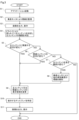
上記の作用について図3以降の図面を参照しながら説明する。図3に示すように、パワースイッチが操作され車両が起動されると、制御装置11は、S1においてナビアプリ等のアプリを起動する。アプリが起動されると、S2において乗員モニタ22を用いて車両乗員の視線を監視し、表示処理部13は、各ディスプレイ3、4bに画像を出力して表示させる。The above operation will be described with reference to Figure 3 and subsequent figures. As shown in Figure 3, when the power switch is operated to start the vehicle, the
制御装置11は、S4においてドライバにより見られているコンテンツを判定し主コンテンツとして認定する。ドライバは、第1の車両乗員相当である。ここでは、ドライバの視線を検知することで何れのディスプレイ3、4bを見ているか判定することで見られているコンテンツを判定できる。In S4, the
制御装置11は、その後、S5において主コンテンツに関連する状況が変化したか否かを判定したり、S6において関連コンテンツの状況が変化したか否かを判定したり、S7において主コンテンツを見る車両乗員が変化したか否かを判定する。The
S5の判定内容「主コンテンツに関連する状況が変化」は、例えば主コンテンツとして電子ミラー4の撮像画像を認定した場合、車両がバックすることで電子ミラー4の撮像画像の中に障害物を画像認識し始める変化を検知した場合などを示している。その他、ドライバにより見られている主コンテンツがクリアランスソナー24aの検知状況Saであった場合、クリアランスソナー24aにより自車両Caの周辺に障害物を検知するなど何らかの変化を検知した場合を示している。すなわち、主コンテンツの中で何らかの変化を生じたときにS5でYESと判定する。The determination in S5 of "the situation related to the main content has changed" indicates, for example, when the image captured by the
また、S6の判定内容「関連コンテンツの状況が変化」は、例えばドライバにより見られている主コンテンツが電子ミラー4の撮像画像であるときに、電子ミラー4の撮像画像に関連する関連コンテンツであるクリアランスソナー24aの検知状況Saに変化したとき、例えば障害物を検知し始めた変化を生じた場合などを示している。
In addition, the judgment content of S6 "the status of related content has changed" indicates, for example, when the main content being viewed by the driver is the image captured by the
また、S6の判定内容「関連コンテンツの状況が変化」は、ドライバにより見られている主コンテンツがクリアランスソナー24aの検知状況Saであるときに、当該クリアランスソナー24aの検知状況Saに関連する電子ミラー4の撮像画像に障害物を検出し始めて撮像画像の画像認識状況に変化を生じた場合などを示している。すなわち、主コンテンツに関連する関連コンテンツに何らかの変化を生じたときにS6でYESと判定する。
The judgment in S6, "the status of related content has changed," indicates a case where, when the main content being viewed by the driver is the detection status Sa of the
制御装置11は、S5において主コンテンツに関連する状況が変化し、又はS6において関連コンテンツの状況が変化した、と判定したときには、S9において表示態様を変更した上で、S10において表示するディスプレイ3、4bを特定し、表示処理部13は、特定されたディスプレイ3、4bに画像を出力して表示させる。
When the
また、S7の判定内容「主コンテンツを見る乗員が変化」は、例えばドライバの視線が主コンテンツから外れると共に、P席の乗員が同じ主コンテンツを見始めたことを検知した場合などを示しており、特定の主コンテンツを見る乗員が変化したときにS7でYESと判定する。P席の乗員は第2
の車両乗員相当である。
The determination in S7 "the passenger viewing the main content has changed" indicates, for example, a case where the driver's line of sight has shifted from the main content and the passenger in the P seat has started viewing the same main content. When the passenger viewing a specific main content has changed, the determination in S7 is YES.
This is equivalent to a vehicle occupant.
制御装置11は、S7において主コンテンツを見る車両乗員自体が変化したと判定したときには、S8において乗員モニタ22を用いて主コンテンツを見ている第2の車両乗員の視線を検知した上で、S9において主コンテンツ又は関連コンテンツの表示態様を変更し、S10において表示するディスプレイ(例えば3、4bなど)を特定し、S11において画像を出力して表示させる。When the
以下、実際の車両運行に適用した適用例を説明する。例えば、ドライバが自車両Caを後退させて駐車場に駐車させるときに、図4及び図5に示すようにセンタディスプレイ3に表示されたクリアランスソナー24aの検知状況Saを見ている場合を考える。An example of application of the present invention to actual vehicle operation is described below. For example, when a driver backs up his/her vehicle Ca to park in a parking lot, he/she is looking at the detection status Sa of the
制御装置11は、ドライバによりクリアランスソナー24aの検知状況Saを見ていることを検知する。このとき、クリアランスソナー24aの検知状況Saが主コンテンツとして認識される。自車両Caの周辺に障害物が存在しないとき、クリアランスソナー24aが近接無反応の場合には、図5に示すように、表示処理部13は、そのままクリアランスソナー24aの検知状況Saをセンタディスプレイ3に表示させる。The
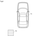
その後、ドライバが自車両Caを後退させたときに、図6に示すように自車両Caの左後方に障害物Obが存在することを想定すると、クリアランスソナー24aにより自車両Caの左後方に障害物Obが検知される。Thereafter, when the driver reverses the vehicle Ca, assuming that an obstacle Ob is present to the left rear of the vehicle Ca as shown in Figure 6, the
このとき、表示処理部13は、クリアランスソナー24aに反応した障害物の検知方向、及び、検知方向の周辺を撮像する周辺カメラ23の撮像画像を関連コンテンツとして視野範囲に表示する。具体的には、表示処理部13は、クリアランスソナー24aの検知状況Saと共に障害物を検知した方向に警告表示を行い、さらに検知状況Saの表示領域に隣接して、クリアランスソナー24aが反応した方向に対応した周辺カメラ23の撮像画像を表示すると良い。図6に示すことを想定した場合には、図7に示すように、左後方を撮像する電子ミラー4のドアミラーカメラ4aの撮像画像を表示させると良い。このとき、表示処理部13は、車両乗員の視野範囲に入るように表示すると良い。At this time, the
これにより、制御装置11の変化検知部11dにより状況変化が検知される前は、表示処理部13は、関連コンテンツとなる電子ミラー4のドアミラーカメラ4aの撮像画像をデフォルトの所定位置となる電子ミラー4のディスプレイ4bに表示し、状況変化が検知された後は、関連コンテンツをセンタディスプレイ3の視野範囲に移動させることができる。このとき、表示処理部13は、デフォルトとして電子ミラー4のディスプレイ4bに表示させていた関連コンテンツを消去しても良いし、電子ミラー4のディスプレイ4bに表示させたまま、センタディスプレイ3に複製して表示しても良い。
なお、クリアランスソナー24aの反応位置に対し、周辺カメラ23のうち何れの方向(前方、後方、前側方、後側方etc)を撮像する画像コンテンツを表示するかは予め決定し、対応関係を記憶部6に予め記憶しておくことが望ましい。
As a result, before a situation change is detected by the
It is desirable to determine in advance which direction (forward, backward, front-side, rear-side, etc.) of the image content captured by the
また表示処理部13は、主コンテンツを見ている車両乗員の位置と主コンテンツとの相対位置関係に応じて関連コンテンツを表示する位置を変更することが望ましい。例えば、主コンテンツを見ているドライバの右側に関連コンテンツが関係するときには、主コンテンツの右側に関連コンテンツを表示させると良く、逆に、図6及び図7に示したように、主コンテンツを見ているドライバの左側に関連コンテンツが関係するときには、主コンテンツの左側に関連コンテンツを表示させると良い。また例えば、P席の乗員がコンテンツを見たことを検知した場合、P席の乗員側に表示しても良い。危険な場所を撮像画像により見せる場合には、主コンテンツを中心として危険箇所の相対位置に表示すると良い。It is also desirable for the
また、この後、ドライバが所定のセンタディスプレイ3の中央脇に視線を移動した場合でも、制御装置11によりこの視線の移動変化を検知し、表示処理部13は、その定められたセンタディスプレイ3に対し、クリアランスソナー24aが反応した方向を撮像する周辺カメラ23の撮像画像を表示すると良い。センタディスプレイ3の中央側に視線を移動した場合、バックカメラの撮像画像を表示すると良い。表示処理部13は、視線の移動先の視野範囲に入るように画像コンテンツを表示させると良い。Furthermore, even if the driver subsequently moves his/her gaze to the side of the center of a specified
クリアランスソナー24aによる障害物の反応が終了した後、視線の移動がされなかった場合でも、周辺カメラ23の撮像画像を一定時間の間、表示を留めておくことが望ましい。これにより、車両乗員は、自車両Caの周辺状況を確認して問題なくなったことを認識できる。これにより、車両乗員が視線の先を変える頻度を減らすことができ、首振り回数を減らすことができる。Even if the line of sight is not moved after the
また、ドライバが自車両Caを後退させ左後方に位置する自宅駐車スペースに駐車させるときに、図8及び図9に示すように、左側の電子ミラー4のディスプレイ4bを確認しながら駐車させる場合を考える。このように、ドライバが左側のドアミラーカメラ4aの撮像画像を見ているときには、制御装置11は、電子ミラー4の撮像画像を主コンテンツとして認定する。
Consider a case where the driver backs up the vehicle Ca and parks it in a home parking space located at the rear left while checking the
自動運転ではなく通常運転する場合、ドライバは走行方向を常に確認しなければならない都合上、そのまま電子ミラー4のディスプレイ4bを継続して見続けながら運転を続けるのは難しい。また狭い道路を走行中に対向車とすれ違う場合、また左右の障害物をすり抜ける場合には、従来通り、左右の電子ミラー4に注意を向けながら運転するほうが良い。このため、制御装置11が、乗員モニタ22によりドライバが電子ミラー4のディスプレイ4bを見ていることを検知した場合、クリアランスソナー24aの検知状況Saを関連コンテンツとし、表示処理部13は、図10に示すように、電子ミラー4の表示領域の一部にクリアランスソナー24aが他の障害物に反応した検知状況Saを表示すると良い。図10に示すように、自車両Caの側後方に他車両Ceが存在したとしても、この方向を認識できる。In normal driving, not automatic driving, the driver must always check the driving direction, so it is difficult to continue driving while continuously looking at the
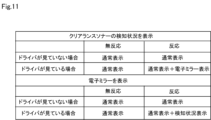
まとめると、図11に示すように、表示処理部13がクリアランスソナー24aの検知状況Saをセンタディスプレイ3に表示している場合、さらにドライバがクリアランスソナー24aの検知状況Saを見ていると判定した場合、表示処理部13は、通常のクリアランスソナー24aの検知状況Saの画像と共に電子ミラー4の撮像画像を同一のディスプレイ3に表示させている。
In summary, as shown in FIG. 11, when the
また、表示処理部13が電子ミラー4のディスプレイ4bに撮像画像を表示すると共に、電子ミラー4がドライバにより見られていると判定した場合、表示処理部13は、通常の電子ミラー4の撮像画像と共に、クリアランスソナー24aの検知状況Saを同一のディスプレイ4bに表示させている。なお、それ以外の場合には、通常の表示を継続している。これにより、ドライバに注意を意識づけることができる。
In addition, when the
運転環境又は交通状況に応じて、ドライバが確認したほうが良く、確認させる必要性の高い画像が複数存在する場合、表示処理部13は、主コンテンツ及び関連コンテンツとして一箇所にまとめて表示処理すると良い。また、乗員が見ている箇所に最適化した表現で表示させることが望ましい。
When there are multiple images that the driver should check depending on the driving environment or traffic conditions, the
また表示処理部13は、運転環境又は交通状況に応じて主コンテンツ及び関連コンテンツに設定される表示優先度の高低により、関連コンテンツを変更又は関連コンテンツの表示態様を変更して表示処理することが望ましい。具体的には、制御装置11は、刻々と変化する運転環境又は交通状況に応じて周辺カメラ23の撮像画像や電子ミラー4の撮像画像に表示優先度を設定し、表示優先度を用いてディスプレイ3、4bに画像を表示させると良い。このとき、表示優先度の高いコンテンツの順にディスプレイ3又は4bに画像を表示させると良い。In addition, it is preferable that the
このとき、関連コンテンツの表示優先度が主コンテンツより高く変更された場合には、関連コンテンツを主コンテンツに対して目立つように表示すると良い。関連コンテンツの状況が変化し、表示優先度が高く変更されたときには当該関連コンテンツ自体を変更したり、また関連コンテンツの表示態様を変更したりして表示処理すると良い。At this time, if the display priority of the related content is changed to be higher than that of the main content, it is recommended to display the related content so that it stands out against the main content. If the situation of the related content changes and its display priority is changed to be higher, it is recommended to display the related content by changing the related content itself or by changing the display mode of the related content.
制御装置11は、周辺カメラ23の撮像画像や自車両Caの挙動を検出することで、運転環境又は場所や時間を含む交通状況の中で自車両Caの置かれている状況を判断できる。By detecting the images captured by the surrounding
例えば、位置特定部11aにより高速道路を走行中であると認められた場合について説明する。高速道路を走行中、制御装置11が自車両Caの周辺に他車両Ceを多く検知すると共に、自車両Caの走行速度が所定の時間内に急速に低下したことを検出した場合、高速道路走行中に渋滞に巻き込まれたという自車両Caの運転環境や交通状況を判定できる。For example, a case will be described in which the
このような運転環境や交通状況が、記憶部6にデータベース化して記憶されていれば、制御装置11は、この記憶部6のデータベースを参照し、周辺カメラ23や距離検出センサ24により自車両Caの周辺に他車両Ceがどの程度密集しているか、又は、自車両Caの周辺に他車両Ceが増加しているか検出することで、渋滞を生じるか否か、又は、どの程度の渋滞を生じるか予測できる。If such driving environment and traffic conditions are stored in a database in the memory unit 6, the
このため、制御装置11は、高速道路を走行中に所定より急減速したと認められたときには、記憶部6のデータベースを参照することで渋滞を生じたと検出、さらにどの程度の渋滞を生じるかを予測し、例えば、地図画面を主コンテンツとして表示するセンタディスプレイ3の中に、周辺カメラ23のうち自車両Caの後続車の状況を映し出すバックカメラの撮像画像を関連コンテンツとしてセンタディスプレイ3に表示させると良い。このように表示処理することで、ドライバに注意喚起できる。For this reason, when the
また例えば、位置特定部11aによりドライバの自宅住所周辺を走行中であると認められた場合について説明する。車両がドライバの自宅住所周辺を走行中であると認められると、制御装置11は、シフトレンジがRレンジに入ったか否かを判定し、記憶部6に記憶されたデータベースを参照することで、自宅駐車スペースに入庫させるときに事故を生じやすい事象を推定し、ディスプレイ3又は4bに表示させる画像の表示優先度に反映させる。
As another example, a case will be described where the
例えば、ドライバがステアリングホイールを左旋回させながら自車両Caを後退させるときには、図10に示したように、ドライバは左側の電子ミラー4のディスプレイ4bの映像を確認しながら自車両Caを後退させる。しかし、ドライバが左側の電子ミラー4のディスプレイ4bに注意しすぎている場合、右側に他の障害物(図示せず)を見落としやすい。この事故の事象が記憶部6のデータベースに登録されていれば、制御装置11はこの事故の事象を参照できる。For example, when the driver reverses the vehicle Ca while turning the steering wheel to the left, the driver reverses the vehicle Ca while checking the image on the
クリアランスソナー24aにより右後方に障害物を検知した場合、図12に示すように、表示処理部13は、関連コンテンツとして表示されている左側の検知状況Saに代えて右側の検知状況Sbを電子ミラー4のディスプレイ4bに表示させると良い。また、図12に示したように、ドライバへ注意を促すように右側の検知状況Sbを検知状況Saに比べて大きく表示させると良い。図12に示す例では、右側の検知状況Sbだけを関連コンテンツとして表示しているが、左側の検知状況Saも合わせて表示しても良い。
When an obstacle is detected to the right rear by the
本実施形態によれば、変化検知部11dによる検知結果に基づいて主コンテンツ又は関連コンテンツの表示態様を変更し、当該主コンテンツ及び関連コンテンツを見る車両乗員の視線の先の視野範囲に表示している。このため、車両乗員は主コンテンツと共に関連コンテンツも同時に確認できる。これにより、車両乗員は視線を移動する回数や首を振る回数を極力減らしつつ適切な情報を確認できる。According to this embodiment, the display mode of the main content or related content is changed based on the detection result by the
(第2実施形態)
第2実施形態について図13から図16を参照しながら説明する。第2実施形態は、乗員がナビアプリに応じて描画される地図画面を見る際の主コンテンツと関連コンテンツとの関係性について説明する。
Second Embodiment
The second embodiment will be described with reference to Fig. 13 to Fig. 16. In the second embodiment, the relationship between the main content and the related content when the occupant views a map screen drawn according to a navigation application will be described.
図13に示す地図画面B1は、ナビアプリの実行に伴いディスプレイ3などに描画される。通常時、表示処理部13は、地図画面B1をセンタディスプレイ3の表示画面いっぱいに大きく表示すると良い。これは、ドライバが通常運転中に前方に注意を払いつつ地図画面B1をちら見して確認したとしても確認しやすくなるためである。すなわち、制御装置11は、乗員モニタ22によりドライバが地図画面B1を見ていることを検知したとき、表示処理部13は地図画面B1をセンタディスプレイ3の表示画面いっぱいに大きく表示し、余計なものを表示しないようにすることが望ましい。
The map screen B1 shown in Figure 13 is drawn on the
なお、乗員が操作しないと必要な情報が表示されないと不便なため、例えば、図14に示すように、地図の方角情報B2、VICS(登録商標)の情報取得時間B3などのように必要な情報を予め表示しておいても良い。 In addition, since it would be inconvenient if the necessary information was not displayed without the occupant's operation, it is also possible to display the necessary information in advance, such as map direction information B2 and VICS (registered trademark) information acquisition time B3, as shown in Figure 14.
また制御装置11は、乗員により地図画面B1が一定時間見られたことを検知したことを条件として、表示処理部13は、図15に示すように、その地図画面B1の補足情報を関連コンテンツとして表示すると良い。図15に示す補足情報は、例えば目的地設定B4や現在地設定B5、その他のナビ設定B6、環境設定B7、地図詳細表示、表示変更、地図表示オフ、目的地セット、地点登録、広域地図変更などの操作指示ボタン表示画面B8のコンテンツである。In addition, when the
すなわち、制御装置11は、ドライバにより見られていない又は一定時間未満だけしか見られていないと判定した場合、表示処理部13は補足情報を表示せず、ドライバにより一定時間見続けられると補足情報を重畳表示する。これにより、段階的に情報を増やしながら情報提供でき、状況に応じた情報を提供できる。ドライバは感覚的に遅れて確認可能な提供情報が増えることになりドライバの認知処理負担も軽減される。
In other words, if the
さらに、制御装置11及び表示処理部13は、ドライバにより見られている場合とP席の乗員により見られている場合とでセンタディスプレイ3に表示するコンテンツを変更すると良い。すなわち制御装置11は、図3のS7において地図画面を見る乗員が変化しP席の乗員によりナビゲーションの地図情報が見られていることが判定された場合、S8においてP席の乗員の視線を検知した上で、表示処理部13はS9からS11において例えば地図画面B1に表示中の現在地近辺で開催されているエンタテイメント情報や、図16に示すように、周辺のおすすめ店舗B9などを関連コンテンツとして表示処理すると良い。Furthermore, the
このとき、表示処理部13は地図画面B1を見ているP席の乗員側に関連コンテンツを表示させると良い。このとき、P席の乗員の視線の視野範囲に表示させると良い。P席の乗員が、視線の移動頻度を減らすことができ、首振りの回数を減らすことができる。At this time, the
また制御装置11は、運転負荷判定部11eによりドライバの運転負荷を判定し、表示処理部13は、ドライバの運転負荷に応じて関連コンテンツの情報量を変更して表示処理することが望ましい。運転負荷は、ドライバ操作による運転アクチュエータや、ナビゲーション表示画面の操作状況、自動運転レベル、又は乗員モニタ22により乗員の状態を周知の技術を用いて検知することで算定できる。In addition, the
例えば、制御装置11が、運転負荷判定部11eによりドライバの運転負荷を標準範囲と判定した場合には、情報量を通常の所定量として表示処理するが、運転負荷を標準より低いと判定した場合には情報量を多くして表示処理しても良い。逆に、ドライバの運転負荷を標準より高いと判定した場合、標準より目立たない表現にしたり情報量を減少させたりすると良い。すなわち、関連コンテンツについては、ドライバの運転負荷に応じて情報量を変更して表示処理すると良い。For example, when the
例えば、停車中、また、その停車中にナビゲーションの目的地や現在地の設定しているときは運転負荷が低いため、関連コンテンツの情報量を標準より多くして表示しても良い。また、レベルIII以上の自動運転中には、ドライバの運転負荷を低いと判定し、同様に情報量を標準より多くして表示しても良い。また、ACCによる追従走行や、レーンキープアシスト(LAS)による定常運転時には、運転負荷を低いと判定し、同様に関連コンテンツの情報量を標準より多くして表示しても良い。For example, when the vehicle is stopped or when the navigation destination or current location is being set while the vehicle is stopped, the driving load is low, so the amount of information on related content may be displayed in a larger amount than standard. Also, during automated driving at level III or higher, the driving load on the driver may be determined to be low, and similarly the amount of information displayed may be larger than standard. Also, during following driving using ACC or steady driving using lane keep assist (LAS), the driving load may be determined to be low, and similarly the amount of information on related content may be displayed in a larger amount than standard.
逆に、制御装置11が、周辺監視センサにより車両の周囲に障害物が所定より多いと判定した場合や、VICS(登録商標)等による交通情報を参照することで周辺の交通量が所定より多い高速道路を走行中であると判定した場合、また、高速道路を走行中に周辺監視センサにより他車両Ceが自車両Caの走行車線に進入すると判定した場合、また、一般道路を走行中でも人物が車両の周囲に存在又は移動していると判定した場合には、運転負荷を高いと判定し、関連コンテンツの情報量を標準より少なくしたり目立たないように表示したりすると良い。Conversely, if the
さらに、レベルIIの運転支援においてレーンチェンジアシストを実行しているとき、特に車両操舵中には法規上ドライバによる監視義務を生じている。なおレーンチェンジアシストはLane Change Assistである。制御装置11はレーンチェンジアシストを実行している最中には運転負荷を高いと判定し、関連コンテンツの情報量を標準より少なくしたり目立たないように表示したりすると良い。
Furthermore, when lane change assist is being performed in level II driving assistance, the driver is legally obligated to monitor, especially while steering the vehicle. The lane change assist is called Lane Change Assist. The
表示処理部13は、関連コンテンツが1又は複数の車両乗員による関連コンテンツを確認しているか否かの状況に応じて表示するか否かを決定又は表示態様を変更することが望ましい。状況に応じて、ドライバなどの車両乗員に関連コンテンツを確認させないようにすることで安全性を向上できるためである。It is desirable for the
例えば、表示処理部13が、P席の乗員を対象者として有益な動画コンテンツを関連コンテンツとして表示処理した場合、ドライバには不安全な誘目になる。ドライバがこの関連コンテンツを見たことを検知したときに動画コンテンツの表示をやめると良い。また、制御装置11は、動画コンテンツを見る乗員が複数のときに何れの乗員が見ているかを判定し、ドライバが見ており車両運行の安全性に問題があるときには動画コンテンツの表示をやめることが望ましい。For example, if the
車両が停車中から運転中に変化した場合、ドライバによりエンタメ系の動画コンテンツを見ていることが検知されたときには動画コンテンツを停止することが望ましい。ただし所定のレベル以上の自動運転中、例えばレベルIII以上の自動運転中の場合には、ドライバをP席の乗員同様に扱っても良く、表示処理部13は動画コンテンツを映し続けても良い。When the vehicle changes from being stopped to being driven, it is desirable to stop the video content if it is detected that the driver is watching entertainment video content. However, during autonomous driving at a certain level or higher, for example during autonomous driving at level III or higher, the driver may be treated the same as a passenger in the P seat, and the
(他の実施形態)
本開示は、前述した実施形態に限定されるものではなく、種々変形して実施することができ、その要旨を逸脱しない範囲で種々の実施形態に適用可能である。例えば以下に示す変形又は拡張が可能である。
Other Embodiments
The present disclosure is not limited to the above-described embodiment, and can be implemented in various modifications and variations without departing from the spirit and scope of the present disclosure. For example, the following modifications or extensions are possible.
変化検知部11dによる変化検知条件を満たしたときに、車両乗員の視線の先の視野範囲に主コンテンツ及び関連コンテンツを表示するようにしたが、逆に偏光フィルタなどを用いて見える範囲の広狭を調整して視野範囲に表示するようにしても良い。When the change detection conditions are met by the
図面中、11cは判定部、11dは変化検知部、11eは運転負荷判定部、13は表示処理部、を示す。 In the drawing, 11c indicates a judgment unit, 11d indicates a change detection unit, 11e indicates a driving load judgment unit, and 13 indicates a display processing unit.
本開示に記載の制御装置11、表示処理部13による手法は、コンピュータプログラムにより具体化された一つ乃至は複数の機能を実行するようにプログラムされたプロセッサ及びメモリを構成することにより提供された専用コンピュータにより実現されても良い。或いは、本開示に記載の制御装置11、表示処理部13及びその手法は、一つ以上の専用ハードウェア論理回路によりプロセッサを構成することにより提供された専用コンピュータにより実現されても良い。若しくは、本開示に記載の制御装置11、表示処理部13及びその手法は、一つ乃至は複数の機能を実行するようにプログラムされたプロセッサ及びメモリと一つ以上のハードウェア論理回路により構成されたプロセッサとの組み合わせにより構成された一つ以上の専用コンピュータにより実現されても良い。また、コンピュータプログラムは、コンピュータにより実行されるインストラクションとして、コンピュータ読み取り可能な非遷移有形記録媒体に記憶されていても良い。The
本開示は、前述した実施形態に準拠して記述したが、本開示は当該実施形態や構造に限定されるものではないと理解される。本開示は、様々な変形例や均等範囲内の変形をも包含する。加えて、様々な組み合わせや形態、さらには、それらに一要素、それ以上、あるいはそれ以下、を含む他の組み合わせや形態をも、本開示の範畴や思想範囲に入るものである。Although the present disclosure has been described in accordance with the above-described embodiment, it is understood that the present disclosure is not limited to the embodiment or structure. The present disclosure also encompasses various modifications and modifications within the scope of equivalents. In addition, various combinations and forms, as well as other combinations and forms including one, more, or less than one element, are within the scope and concept of the present disclosure.
Claims (7)
車速センサにより検出された自車両の速度信号から自車両の走行速度が所定の時間内に急速に低下したことを判定し、前記地図画面に関連する関連コンテンツとしてバックカメラの撮像画像の状況変化を検知することで自車両の周辺に他車両が増加したと判定する変化検知部(11d)と、
前記変化検知部による検知結果に基づいて前記バックカメラの撮像画像の表示態様を変更し、前記地図画面及び前記バックカメラの撮像画像を前記車両乗員の視線の先の視野範囲に表示する表示処理部(13)と、を備える車両用表示システム。 a determination unit (11c) for determining whether a main content being viewed by a vehicle occupant is a map screen ;
a change detection unit (11d) that determines that the traveling speed of the vehicle has suddenly decreased within a predetermined time from a speed signal of the vehicle detected by a vehicle speed sensor, and determines that the number of other vehicles has increased around the vehicle by detecting a change in a situation in an image captured by a backup camera as a related content related to the map screen;
a display processing unit (13) that changes the display mode of the image captured by the rear camera based on the detection result by the change detection unit, and displays the map screen and the image captured by the rear camera in the field of view ahead of the line of sight of the vehicle occupant.
変化検知部(11d)が、車速センサにより検出された自車両の速度信号から自車両の走行速度が所定の時間内に急速に低下したことを判定し、前記地図画面に関連する関連コンテンツとしてバックカメラの撮像画像の状況変化を検知することで自車両の周辺に他車両が増加したと判定し、
表示処理部(13)が、前記変化検知部による検知結果に基づいて前記バックカメラの撮像画像の表示態様を変更し、前記地図画面及び前記バックカメラの撮像画像を前記車両乗員の視線の先の視野範囲に表示する、車両用表示方法。 A determination unit (11c) determines whether the main content being viewed by the vehicle occupant is a map screen ;
A change detection unit (11d) determines that the traveling speed of the vehicle has rapidly decreased within a predetermined time from a speed signal of the vehicle detected by a vehicle speed sensor, and determines that the number of other vehicles has increased around the vehicle by detecting a change in the situation of an image captured by a backup camera as related content related to the map screen;
A display processing unit (13) changes the display mode of the image captured by the rear camera based on the detection result by the change detection unit, and displays the map screen and the image captured by the rear camera within the field of view of the vehicle occupant.
変化検知部(11d)に、車速センサにより検出された自車両の速度信号から自車両の走行速度が所定の時間内に急速に低下したことを判定させ、前記地図画面に関連する関連コンテンツとしてバックカメラの撮像画像の状況変化を検知することで自車両の周辺に他車両が増加したと判定させる手順と、
表示処理部(13)に、前記変化検知部による検知結果に基づいて前記バックカメラの撮像画像の表示態様を変更し、前記地図画面及び前記バックカメラの撮像画像を前記車両乗員の視線の先の視野範囲に表示させる手順と、を備える車両用表示プログラム。 a step of causing a determination unit (11c) to determine whether a main content being viewed by a vehicle occupant is a map screen ;
a step of causing a change detection unit (11d) to determine that the traveling speed of the vehicle has rapidly decreased within a predetermined time from a speed signal of the vehicle detected by a vehicle speed sensor, and to determine that the number of other vehicles has increased around the vehicle by detecting a change in the situation of an image captured by a backup camera as related content related to the map screen ;
A display program for a vehicle, comprising a procedure in which a display processing unit (13) changes the display mode of the image captured by the rear camera based on the detection result by the change detection unit , and displays the map screen and the image captured by the rear camera within the field of view of the vehicle occupant's line of sight.
Priority Applications (1)
| Application Number | Priority Date | Filing Date | Title |
|---|---|---|---|
| JP2024185904A JP2025020179A (en) | 2021-06-02 | 2024-10-22 | Vehicle display system, vehicle display method, and vehicle display program |
Applications Claiming Priority (3)
| Application Number | Priority Date | Filing Date | Title |
|---|---|---|---|
| JP2021092992 | 2021-06-02 | ||
| JP2021092992 | 2021-06-02 | ||
| PCT/JP2022/022323 WO2022255409A1 (en) | 2021-06-02 | 2022-06-01 | Vehicle display system, vehicle display method, vehicle display program |
Related Child Applications (1)
| Application Number | Title | Priority Date | Filing Date |
|---|---|---|---|
| JP2024185904A Division JP2025020179A (en) | 2021-06-02 | 2024-10-22 | Vehicle display system, vehicle display method, and vehicle display program |
Publications (3)
| Publication Number | Publication Date |
|---|---|
| JPWO2022255409A1 JPWO2022255409A1 (en) | 2022-12-08 |
| JPWO2022255409A5 JPWO2022255409A5 (en) | 2023-12-28 |
| JP7616372B2 true JP7616372B2 (en) | 2025-01-17 |
Family
ID=84324177
Family Applications (2)
| Application Number | Title | Priority Date | Filing Date |
|---|---|---|---|
| JP2023525891A Active JP7616372B2 (en) | 2021-06-02 | 2022-06-01 | Vehicle display system, vehicle display method, and vehicle display program |
| JP2024185904A Pending JP2025020179A (en) | 2021-06-02 | 2024-10-22 | Vehicle display system, vehicle display method, and vehicle display program |
Family Applications After (1)
| Application Number | Title | Priority Date | Filing Date |
|---|---|---|---|
| JP2024185904A Pending JP2025020179A (en) | 2021-06-02 | 2024-10-22 | Vehicle display system, vehicle display method, and vehicle display program |
Country Status (2)
| Country | Link |
|---|---|
| JP (2) | JP7616372B2 (en) |
| WO (1) | WO2022255409A1 (en) |
Citations (3)
| Publication number | Priority date | Publication date | Assignee | Title |
|---|---|---|---|---|
| JP2003214878A (en) | 2002-01-17 | 2003-07-30 | Hitachi Ltd | On-vehicle display device |
| US20170364148A1 (en) | 2016-06-15 | 2017-12-21 | Lg Electronics Inc. | Control device for vehicle and control method thereof |
| JP2019176330A (en) | 2018-03-28 | 2019-10-10 | ダイハツ工業株式会社 | Display device |
Family Cites Families (7)
| Publication number | Priority date | Publication date | Assignee | Title |
|---|---|---|---|---|
| JP2003320869A (en) * | 2002-04-30 | 2003-11-11 | Nissan Motor Co Ltd | Information display device for vehicles |
| JP2008306402A (en) * | 2007-06-06 | 2008-12-18 | Auto Network Gijutsu Kenkyusho:Kk | In-vehicle imaging display device |
| JP6252365B2 (en) * | 2014-06-11 | 2017-12-27 | 株式会社デンソー | Safety confirmation support system, safety confirmation support method |
| JP2016084021A (en) * | 2014-10-27 | 2016-05-19 | 三菱電機株式会社 | Vehicle display device and vehicle display system |
| JP2019101634A (en) * | 2017-11-30 | 2019-06-24 | パイオニア株式会社 | Information presentation control device, information presentation control method, and program |
| JP7147370B2 (en) * | 2018-08-24 | 2022-10-05 | 日本精機株式会社 | Display device |
| JP7293990B2 (en) * | 2019-08-28 | 2023-06-20 | 株式会社Jvcケンウッド | Vehicle display control device, vehicle display control method, and program |
-
2022
- 2022-06-01 JP JP2023525891A patent/JP7616372B2/en active Active
- 2022-06-01 WO PCT/JP2022/022323 patent/WO2022255409A1/en not_active Ceased
-
2024
- 2024-10-22 JP JP2024185904A patent/JP2025020179A/en active Pending
Patent Citations (3)
| Publication number | Priority date | Publication date | Assignee | Title |
|---|---|---|---|---|
| JP2003214878A (en) | 2002-01-17 | 2003-07-30 | Hitachi Ltd | On-vehicle display device |
| US20170364148A1 (en) | 2016-06-15 | 2017-12-21 | Lg Electronics Inc. | Control device for vehicle and control method thereof |
| JP2019176330A (en) | 2018-03-28 | 2019-10-10 | ダイハツ工業株式会社 | Display device |
Also Published As
| Publication number | Publication date |
|---|---|
| JPWO2022255409A1 (en) | 2022-12-08 |
| JP2025020179A (en) | 2025-02-12 |
| WO2022255409A1 (en) | 2022-12-08 |
Similar Documents
| Publication | Publication Date | Title |
|---|---|---|
| US12485761B2 (en) | Vehicle display system, vehicle display method, and storage medium | |
| JP7424327B2 (en) | Vehicle display control device, vehicle display control system, and vehicle display control method | |
| JP5160564B2 (en) | Vehicle information display device | |
| US7680592B2 (en) | System and apparatus for drive assistance | |
| WO2017086000A1 (en) | Driving assistance device | |
| CN108140314A (en) | Parking assistance method and parking aid | |
| JP4517393B2 (en) | Driving assistance device | |
| CN102933428A (en) | Drive assist device | |
| US12515520B2 (en) | Vehicle display system, vehicle display method, and computer-readable non-transitory storage medium storing vehicle display program | |
| JP7666549B2 (en) | Image Processing Device | |
| JP2025089463A (en) | In-vehicle display device, method and program | |
| WO2020003750A1 (en) | Vehicle display control device, vehicle display control method, and control program | |
| CN111461096A (en) | Display device for vehicle | |
| US12600231B2 (en) | Vehicle display system, vehicle display method, and storage medium storing vehicle display program | |
| CN120693271A (en) | Automatic driving control device, automatic driving control program, and automatic driving control method | |
| US11613252B2 (en) | Driving assistance system and control method thereof | |
| WO2022210171A1 (en) | Vehicle display system, vehicle display method, and vehicle display program | |
| JP2022049711A (en) | Vehicular control device and method | |
| JP7616372B2 (en) | Vehicle display system, vehicle display method, and vehicle display program | |
| JP7428161B2 (en) | Vehicle display system, vehicle display method, and vehicle display program | |
| US20250218065A1 (en) | Information processing apparatus and information processing method | |
| JP7816091B2 (en) | Vehicle control device, vehicle control method, and vehicle control program | |
| JP7467521B2 (en) | Control device | |
| JP7713814B2 (en) | MOBILE BODY CONTROL DEVICE, MOBILE BODY CONTROL METHOD, AND PROGRAM | |
| JP2025138221A (en) | Vehicle notification control device, vehicle notification control system, vehicle notification control method, and vehicle notification control program |
Legal Events
| Date | Code | Title | Description |
|---|---|---|---|
| A521 | Request for written amendment filed |
Free format text: JAPANESE INTERMEDIATE CODE: A523 Effective date: 20230927 |
|
| A621 | Written request for application examination |
Free format text: JAPANESE INTERMEDIATE CODE: A621 Effective date: 20230927 |
|
| A131 | Notification of reasons for refusal |
Free format text: JAPANESE INTERMEDIATE CODE: A131 Effective date: 20240827 |
|
| A521 | Request for written amendment filed |
Free format text: JAPANESE INTERMEDIATE CODE: A523 Effective date: 20241022 |
|
| TRDD | Decision of grant or rejection written | ||
| A01 | Written decision to grant a patent or to grant a registration (utility model) |
Free format text: JAPANESE INTERMEDIATE CODE: A01 Effective date: 20241203 |
|
| A61 | First payment of annual fees (during grant procedure) |
Free format text: JAPANESE INTERMEDIATE CODE: A61 Effective date: 20241216 |
|
| R150 | Certificate of patent or registration of utility model |
Ref document number: 7616372 Country of ref document: JP Free format text: JAPANESE INTERMEDIATE CODE: R150 |