JP7619040B2 - Remote control device, communication environment transmission device, and communication environment confirmation program - Google Patents
Remote control device, communication environment transmission device, and communication environment confirmation program Download PDFInfo
- Publication number
- JP7619040B2 JP7619040B2 JP2020212383A JP2020212383A JP7619040B2 JP 7619040 B2 JP7619040 B2 JP 7619040B2 JP 2020212383 A JP2020212383 A JP 2020212383A JP 2020212383 A JP2020212383 A JP 2020212383A JP 7619040 B2 JP7619040 B2 JP 7619040B2
- Authority
- JP
- Japan
- Prior art keywords
- vehicle
- communication
- ultrasonic
- remote control
- information
- Prior art date
- Legal status (The legal status is an assumption and is not a legal conclusion. Google has not performed a legal analysis and makes no representation as to the accuracy of the status listed.)
- Active
Links
Images



Classifications
-
- G—PHYSICS
- G01—MEASURING; TESTING
- G01H—MEASUREMENT OF MECHANICAL VIBRATIONS OR ULTRASONIC, SONIC OR INFRASONIC WAVES
- G01H17/00—Measuring mechanical vibrations or ultrasonic, sonic or infrasonic waves, not provided for in the other groups of this subclass
-
- B—PERFORMING OPERATIONS; TRANSPORTING
- B60—VEHICLES IN GENERAL
- B60R—VEHICLES, VEHICLE FITTINGS, OR VEHICLE PARTS, NOT OTHERWISE PROVIDED FOR
- B60R16/00—Electric or fluid circuits specially adapted for vehicles and not otherwise provided for; Arrangement of elements of electric or fluid circuits specially adapted for vehicles and not otherwise provided for
- B60R16/02—Electric or fluid circuits specially adapted for vehicles and not otherwise provided for; Arrangement of elements of electric or fluid circuits specially adapted for vehicles and not otherwise provided for electric constitutive elements
- B60R16/037—Electric or fluid circuits specially adapted for vehicles and not otherwise provided for; Arrangement of elements of electric or fluid circuits specially adapted for vehicles and not otherwise provided for electric constitutive elements for occupant comfort, e.g. for automatic adjustment of appliances according to personal settings, e.g. seats, mirrors, steering wheel
-
- G—PHYSICS
- G08—SIGNALLING
- G08C—TRANSMISSION SYSTEMS FOR MEASURED VALUES, CONTROL OR SIMILAR SIGNALS
- G08C23/00—Non-electrical signal transmission systems, e.g. optical systems
- G08C23/02—Non-electrical signal transmission systems, e.g. optical systems using infrasonic, sonic or ultrasonic waves
-
- H—ELECTRICITY
- H04—ELECTRIC COMMUNICATION TECHNIQUE
- H04B—TRANSMISSION
- H04B11/00—Transmission systems employing ultrasonic, sonic or infrasonic waves
-
- H—ELECTRICITY
- H04—ELECTRIC COMMUNICATION TECHNIQUE
- H04W—WIRELESS COMMUNICATION NETWORKS
- H04W4/00—Services specially adapted for wireless communication networks; Facilities therefor
- H04W4/30—Services specially adapted for particular environments, situations or purposes
- H04W4/40—Services specially adapted for particular environments, situations or purposes for vehicles, e.g. vehicle-to-pedestrians [V2P]
- H04W4/48—Services specially adapted for particular environments, situations or purposes for vehicles, e.g. vehicle-to-pedestrians [V2P] for in-vehicle communication
-
- H—ELECTRICITY
- H04—ELECTRIC COMMUNICATION TECHNIQUE
- H04W—WIRELESS COMMUNICATION NETWORKS
- H04W4/00—Services specially adapted for wireless communication networks; Facilities therefor
- H04W4/80—Services using short range communication, e.g. near-field communication [NFC], radio-frequency identification [RFID] or low energy communication
Landscapes
- Engineering & Computer Science (AREA)
- Computer Networks & Wireless Communication (AREA)
- Signal Processing (AREA)
- Physics & Mathematics (AREA)
- General Physics & Mathematics (AREA)
- Mechanical Engineering (AREA)
- Selective Calling Equipment (AREA)
- Fittings On The Vehicle Exterior For Carrying Loads, And Devices For Holding Or Mounting Articles (AREA)
- Traffic Control Systems (AREA)
Description
本発明は、車載機器とコントロール端末との間で行われる超音波通信の品質確認技術に関する。 The present invention relates to a technology for checking the quality of ultrasonic communication between an in-vehicle device and a control terminal.
近年では、走行中の車両内において運転者が携帯端末やリモートコントローラ(以下、総称して「コントロール端末」という)を用いてエアコンやナビゲーション等の車載機器を遠隔操作する技術が開発されている。車載機器とコントロール端末との通信手段として電波通信又は赤外線通信が用いられることが多い。この他に超音波を用いた超音波通信も知られている。 In recent years, technologies have been developed that allow drivers to remotely operate in-vehicle equipment such as air conditioners and navigation systems using mobile terminals or remote controllers (hereafter collectively referred to as "control terminals") while the vehicle is moving. Radio wave or infrared communication is often used as a means of communication between the in-vehicle equipment and the control terminal. In addition, ultrasonic communication using ultrasonic waves is also known.
超音波は超音波通信に用いられる非可聴音域(およそ18kHz以上)で環境音等何らかの外乱で容易に乱されるため、超音波通信の内容が受信端末で正しく受信されないことがある。例えば、ビニル袋がこすれる音には非可聴音域の成分を含むため、超音波通信を阻害する要因になる。
しかしながら、ユーザは超音波を感知できないためこのような外乱の発生を認識することができず、システムが使用できる状態にあるか否かを知り得ない。
Since ultrasonic waves are in the inaudible frequency range (approximately 18 kHz or higher) used for ultrasonic communication and are easily disturbed by some kind of disturbance such as environmental noise, the contents of ultrasonic communication may not be received correctly by the receiving terminal. For example, the sound of a plastic bag rubbing against another contains inaudible sound components and can be a factor that impedes ultrasonic communication.
However, since the user cannot sense ultrasonic waves, he or she cannot recognize the occurrence of such a disturbance, and therefore cannot know whether the system is in a usable state or not.
本発明はこのような事情を考慮してなされたもので、ユーザが超音波通信の通信環境を確認することができる遠隔操作装置、通信環境発信装置、及び通信環境確認プログラムを提供することを目的とする。 The present invention has been made in consideration of these circumstances, and aims to provide a remote control device, a communication environment transmission device, and a communication environment confirmation program that allow a user to check the communication environment for ultrasonic communication.
本発明に係る遠隔操作装置は、車載機器の動作を制御する超音波信号を発信可能なスピーカと、車両内のノイズ音に関する情報を検出する情報取得部と、前記情報から前記超音波信号の伝達容易度を算出する制御部と、算出された前記伝達容易度を前記超音波信号の通信品質レベルとして表示する表示部と、を備えるものである。 The remote control device according to the present invention includes a speaker capable of emitting an ultrasonic signal for controlling the operation of an in-vehicle device, an information acquisition unit for detecting information related to noise sounds inside the vehicle, a control unit for calculating the degree of transmission ease of the ultrasonic signal from the information, and a display unit for displaying the calculated degree of transmission ease as a communication quality level of the ultrasonic signal.
本発明に係る通信環境発信装置は、車載機器の動作を制御する信号を超音波通信で発信可能な遠隔操作装置から前記信号を前記超音波通信で受信可能な通信環境発信装置であって、車両内に設けられて前記超音波通信を阻害しうる前記車両内のノイズ音に関する情報を取得する検出部と、前記車両内に設けられて前記車両内の前記ノイズ音に関する前記情報を前記遠隔操作装置と前記通信環境発信装置との間の前記超音波通信の伝達容易度を算出するための環境通知信号に変換して前記車両内に配置された前記遠隔操作装置に発信する発信部と、を備えるものである。 The communication environment transmitting device of the present invention is a communication environment transmitting device capable of receiving a signal controlling the operation of in-vehicle equipment via ultrasonic communication from a remote control device capable of transmitting the signal via ultrasonic communication , and is equipped with a detection unit installed within the vehicle for acquiring information regarding noise sounds within the vehicle that may interfere with the ultrasonic communication , and a transmitting unit installed within the vehicle for converting the information regarding the noise sounds within the vehicle into an environment notification signal for calculating the ease of transmission of the ultrasonic communication between the remote control device and the communication environment transmitting device, and transmitting the information to the remote control device installed within the vehicle.
本発明に係る通信環境確認プログラムは、車載機器の動作を超音波信号で制御するコンピュータに、車両内のノイズ音に関する情報を受信するステップ、前記情報から前記超音波信号の伝達容易度を算出するステップ、算出された前記伝達容易度を前記超音波信号の通信品質レベルとして表示するステップ、を実行させるものである。 The communication environment confirmation program of the present invention causes a computer that controls the operation of an in-vehicle device with an ultrasonic signal to execute the steps of receiving information about noise sounds inside the vehicle, calculating the transmission ease of the ultrasonic signal from the information, and displaying the calculated transmission ease as the communication quality level of the ultrasonic signal.
本発明により、ユーザが超音波通信の通信環境を確認することができる遠隔操作装置、通信環境発信装置、及び通信環境確認プログラムが提供される。 The present invention provides a remote control device, a communication environment transmission device, and a communication environment confirmation program that allow a user to check the communication environment for ultrasonic communication.
以下、本発明の実施形態を添付図面に基づいて説明する。 The following describes an embodiment of the present invention with reference to the attached drawings.
(第1実施形態) (First embodiment)
まず、図1~図4を用いて、遠隔操作装置10(以下、単に「操作装置10」という)及びこの操作装置10に超音波信号Ωで操作される車載機器(51~54)(以下、「対象車載機器(51~54)」という)について説明する。
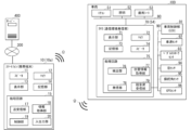
図1は、第1実施形態に係る操作装置10及び対象車載機器(51~54)を搭載した車両100の概念的な構成図である。
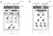
図2(A),(B)は、第1実施形態に係る操作装置10の一例であるスマートフォン10aの概略図である。
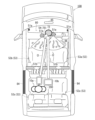
図3は、第1実施形態に係る発信装置70及び対象車載機器(51~54)を搭載した車両100の車内をルーフ側から見下ろした概略図である。
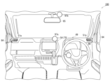
図4は、第1実施形態に係る発信装置70が設けられたインナーパネル80周辺の概略図である。
First, using Figures 1 to 4, we will explain the remote control device 10 (hereinafter simply referred to as the "
FIG. 1 is a conceptual configuration diagram of a
2A and 2B are schematic diagrams of a
FIG. 3 is a schematic diagram of the interior of a
FIG. 4 is a schematic diagram of the periphery of an
<操作装置10>
操作装置10は、例えば図2(A),(B)のようなスマートフォンなどユーザ200が所有する携帯端末10aである。操作装置10は、この他にPC(Personal Computer)、ウェアラブル装置、公共端末、専用に設計製造されたリモートコントローラ、又は後部座席53c(図3)周辺に設置された車内操作端末10b等であってもよい。
以下の実施形態では、適宜、スマートフォン10a(携帯端末10a)に遠隔操作用に開発されたアプリケーションプログラムを別途インストールすることで操作装置10として使用する例で説明する。
<
The
In the following embodiment, an example will be described in which an application program developed for remote control is separately installed on a
操作装置10は、図1に示されるように、スピーカ11、マイク12、表示部13、記憶部14、及び処理回路15を備える。記憶部14は、例えばROM(Read Only Memory)、RAM(Random Access Memory)、或いはHDD(Hard Disk Drive)で構成される。
また、処理回路15は、この記憶部14に保存されたプログラムを実行することで、送受信部17、情報取得部18、制御部19、及び入出力部20の機能を発揮する。
1, the
In addition, the
送受信部17は、スピーカ11を介して対象車載機器(51~54)の動作を制御する超音波信号Ωを発信する。スピーカ11は、オーディオ用に設けられた既存のものであってもよいし、超音波通信用に別途設けられた専用スピーカであってもよい。この超音波信号Ωによって遠隔操作される対象車載機器(51~54)は、例えば、エアコンディショナー51(以下、「エアコン51」という)、照明52、座席シート53又はIVI54(In-Vehicle Infotainment)である。なお、対象車載機器は、ドア開閉レバーのロック機構や、車載カメラ、従来式のナビゲーションやオーディオ機器等、電子制御可能な車載アクセサリであれば特に上述の例に限定されない。
The transmitter/
IVI54とは、例えば、ナビゲーション機能、位置情報サービス機能、音楽や動画などのマルチメディア再生機能、音声通信機能、データ通信機能、インターネット接続機能などを複合的に提供するシステムである。
IVI54については後述の車両100の説明で詳述する。
The IVI 54 is a system that provides a combination of functions, such as a navigation function, a location information service function, a multimedia playback function for music and videos, a voice communication function, a data communication function, and an Internet connection function.
The IVI 54 will be described in detail later in the description of the
各対象車載機器(51~54)は、CAN(Controller Area Network)又はLIN(Local Interconnect Network)等の車内の通信ネットワーク90で接続される。例えばIVI54に超音波受信部79を設け、この超音波受信部79で操作装置10の発する超音波信号Ωを受信する。そして、IVI54が中継機として通信ネットワーク90を介して対象車載機器(51~54)へ操作指示を伝達する。
なお、各対象車載機器(51~54)は、各自で超音波受信部79を備え、操作装置10Aから直接機能発揮ための遠隔操作を受けてもよい。遠隔操作を受けて、例えばIVI54のマルチメディア再生機能においては、起動、停止、音量の増減、メディア再生、早送り又は早戻しの機能が実行される。
The target in-vehicle devices (51 to 54) are connected to an in-
Each of the target in-vehicle devices (51 to 54) may have its own
なお、以下では、対象車載機器(51~54)がIVI54であり、超音波信号Ωを感知可能なIVI54のマイク72が、図3及び図4に示されるように、インナーパネル80上で運転席53aと助手席53bとの間に設けられた表示部71に設けられている例で説明する。
なお、超音波通信のコマンドは、インターネット300で接続されるサーバ400から取得してもよい。また、基本的なコマンドは各装置(10,70)の記憶部14,73が備え、追加的なコマンドはサーバ400から取得するといった方法でもよい。
In the following, an example will be described in which the target in-vehicle device (51 to 54) is an
The ultrasonic communication command may be acquired from a
操作装置10の構成の説明に戻る。
情報取得部18は、車両100内のノイズ音に関する情報(以下、「ノイズ関連情報」という)を検出する。
ここでノイズ関連情報とは、車両100の走行速度、車両100の走行加速度、窓84の開度又はエアコン51の風量等、超音波通信を阻害する外乱または外乱を生じさせる原因に関する情報である。
Returning to the description of the configuration of the
The
Here, noise-related information refers to information regarding disturbances that impede ultrasonic communication or causes of disturbances, such as the traveling speed of the
例えば、図3のエアコン51の吹出口51aから送られる空調風σは、周辺空気との温度差により、ユーザ200が操作する携帯端末10aとIVI54のマイク72との間に温度境界面を形成する。
後部座席53cに着座したユーザ200が保持する携帯端末10aとIVI54との間には、前部座席用エアコンの吹出口51a及び後部座席用エアコンの吹出口51bから送風される空調風σが流れる。空調風σと周辺空気との境界に形成される温度境界面に超音波信号Ωが進入すると温度境界面で反射するなどして乱され、超音波通信へ大きく影響を及ぼすおそれがある。
そこで、情報取得部18は、携帯端末10aのマイク12を介して車両100内の送風音を取得する。
For example, the conditioned air σ sent from the
The conditioned air σ blown from the
Therefore, the
また、エアコン51を稼働させると、例えば空調風σが吹出口51a,51bから出る際に吹出口51a,51bのフィンと接触する音やモータ音等のエアコン51の稼働音も発生する。この稼働音には超音波信号Ωで使用する帯域に外乱となる超音波も含まれる場合があるため、このような稼働音もノイズ関連情報に含まれる。なお、情報取得部18は、このような車両100内の機器の稼働音に含まれる超音波をノイズ関連情報として直接的に取得してもよい。
Furthermore, when the
なお、操作装置10のマイク12が超音波を感知できない場合でも、情報取得部18が機械学習などで稼働音から超音波を推定することを学習しておくことで、既存のマイク12で収集した車載機器の稼働音から超音波成分を高い精度で推定することができる。特に、車両100に特有の障害周波数域を予め情報取得部18に学習させることで、一見関連がなさそうな車内のノイズ音でもノイズ関連情報に含めることができるようになる。
Even if the
また、情報取得部18は、携帯端末10aに搭載されるGPS機能で携帯端末10aの移動速度を割り出し、車両100の走行態様を割り出してもよい。例えば、車両100がコースト走行をしている時、急加速をしている時又は電動走行している時で発生する超音波を推測することができる。
In addition, the
制御部19は、取得されたノイズ関連情報から超音波信号Ωの伝達容易度を算出する。例えば、送風音が大きい場合、車内の空気循環が激しく超音波信号Ωの伝達容易度は低いと推測することができる。また、この送風音に含まれる超音波が超音波信号Ωの周波数からかけ離れた周波数を有する場合、伝達容易度に及ぼす影響は少ない。
また、制御部19は、エアコン51の稼働音についてもこの稼働音が超音波通信帯域で発生させる外乱の強度が算出され、この強度から伝達容易度が算出される。
The
The
また、超音波は、窓84が開くことによる空気の出入りや、窓84の開閉音、車両100の駆動源やバッテリから発生するスイッチングノイズ等からも発生しうる。これらのノイズも超音波通信を阻害することがあるため、このようなノイズもノイズ関連情報に含まれる。
Ultrasonic waves can also be generated by air entering and exiting when the
表示部13は、例えば、ユーザ200の操作に応じたデータ入力を行うための入力デバイスと、データ表示を行うための液晶表示装置等の表示デバイスと、を兼ね備えたタッチパネルである。
表示部13には、例えば図2(A),(B)に示されるように、「IVI」、「エアコン」、「照明」、及び「シート」の操作ページ21が、タブ22で切り替え可能に表示される。
例えば、図2(A)ではエアコン51を、図2(B)ではIVI54を操作するための操作ページ21が表示されている。図2(A)のエアコン51の操作ページ21上では、循環切替ボタン23a、AUTOボタン23b、風量ボタン23c、コンプレッサ駆動ボタン23d等8つのボタン(23a~23h)でエアコン51が遠隔操作で調整される。
The
As shown in FIGS. 2A and 2B, for example, the
For example, Fig. 2(A) shows an
また、「IVI」のタブ22をタッチすると、図2(B)のIVI54の操作ページ21に切り替わり、チャンネルボタン24a,24bなどの各種のボタン(24a~24g)でIVI54が遠隔操作される。
なお、図示を省略するが、照明52については明るさ調整及びON/OFFが遠隔操作される。また、座席シート53についてはリクライニングの角度調整及び座席の前後位置調整が遠隔操作される。
Moreover, when the "IVI"
Although not shown in the drawings, the brightness adjustment and ON/OFF of the
また、表示部13(表示画面26)の上端のステータスバー27には、携帯端末10aのバッテリ残存量や無線通信用の電波強度の状態を示す各種アイコン31が表示される。
そして、第1実施形態に係る携帯端末10aでは、表示部13が例えばこのステータスバー27に、算出された伝達容易度を超音波信号Ωの通信品質レベルとして表示する。
通信品質レベルは、例えば、図2(A),(B)に示されるような0~3本の円弧28の本数で4段階に表される。
Additionally, a
In the
The communication quality level is expressed in four stages by the number of
超音波信号Ωの通信環境が良く伝達容易度が高い場合には、図2(A)のように3本の円弧28をアイコン31で表示し、伝達容易度が1レベル下がると図2(B)のように2本の円弧28を表示する。
なお、通信品質レベルの表示形式は、図2(A),(B)の円弧28を同心円状に並べた扇形のアイコン31に限定されず、例えばアンテナバーの本数や数字で表してもよい。
また、通信品質レベルの表示箇所もステータスバー27に特に限定されず、ユーザ200が視認できれば表示画面26上のどこであってもよい。
When the communication environment for the ultrasonic signal Ω is good and the degree of transmission ease is high, three
The display format of the communication quality level is not limited to the
Furthermore, the location where the communication quality level is displayed is not particularly limited to the
また、伝達容易度に対応させて、ユーザ200へ「携帯端末を車載受信部に向けてください」、「携帯端末を車載受信部に近づけてください」などの文言を表示させ、伝達容易度が改善するための具体的な動作をユーザへ報知してもよい。さらに、表示画面26への表示に代えて音声で通知してもよく、その報知態様は特に限定されない。このように具体的動作を通知することで、ユーザは単に通信品質レベルが低いことを把握するだけでなく、通信品質レベルを上げる具体的な対応を自らもとれるようになる。
In addition, depending on the degree of ease of communication, a message such as "Point the mobile terminal at the vehicle receiving unit" or "Bring the mobile terminal closer to the vehicle receiving unit" may be displayed to the
携帯端末10aがこのような通信環境確認機能を有することで、ユーザ200は遠隔操作の開始前又は操作中に操作装置10上で通信品質レベルを確認し、超音波通信が使用可能か否かを把握することができる。
また、通信環境確認機能を繰り返し利用することで、どのような状況で超音波通信の使用が困難になるかを予測できるようになる。
By providing the
In addition, by repeatedly using the communication environment confirmation function, it becomes possible to predict the circumstances in which it will be difficult to use ultrasonic communication.
<車両100>
次に、図1に加えて図3及び図4を用いて、操作装置10と協働する通信環境発信装置70(以下、単に「発信装置70」という)及びこの発信装置70を搭載した車両100について説明する。
車両100は、車両制御部91(ECU;Electronic Control Unit)、各種センサ(92~96)、IVI54、及び対象車載機器(51~54)を搭載する。
これらの機器(91~96)は、上述の通信ネットワーク90で相互に接続されて情報を送受信する。
<
Next, a communication environment transmitting device 70 (hereinafter simply referred to as "transmitting
The
These devices (91 to 96) are interconnected via the above-mentioned
ECU91は、車両100内の各所に複数設けられる車載コンピュータであり、例えば、エンジン制御機能、ハンドル制御機能、ブレーキ制御機能、及びデータセキュリティ機能を有する。例えばブレーキ制御用のECU91は、ペダルストロークセンサ93及び車速センサ92を介してアクセルペダル及びブレーキペダルの操作、及び走行速度の情報を受信し、これらの情報を制御信号に変換して前輪部又は後輪部へ駆動力又は制動力を付与する。
ECU91 is an on-board computer provided in multiple locations within
IVI54は、例えばユーザ200の操作に応じたデータ入力を行うための入力デバイスと、データ表示を行うための液晶表示装置等の表示デバイスと、を兼ね備えたタッチパネル式の表示部71を有する。
IVI54は、この他に、車載マイク72、車載記憶部73、車載スピーカ74及び車載処理回路75を備える。なお、IVI54の説明に際し、携帯端末10a中のスピーカ11、マイク12、表示部13、記憶部14、及び処理回路15と区別するために、IVI54の各部名称の先頭に適宜「車載」の名称を付す。
The
The
車載記憶部73は、例えばROM、RAM、又はHDDで構成される。
車載記憶部73に保存されたプログラムに従って車載処理回路75が命令を実行処理することで、IVI54は、上述したナビゲーション機能及び位置情報サービス機能などの各種機能を発揮する。
The in-
The in-
ところで、前述したように、エアコン51の吹出口51a,51bは、空調風σを送る対象に合わせて車両100内に複数設けられる。
前部座席53a,53b用に設けられた吹出口51aは、IVI54の表示部71付近にある一方、後部座席53cからは距離がある。よって、この吹出口51aから空調風σが送風されても後部座席53cに着座したユーザ200の携帯端末10aではその送風が十分には感知されない。しかし、携帯端末10aで感知されない場合でも、この空調風σはIVI54付近に温度境界層を形成して超音波通信を阻害する要因になる。
As described above, a plurality of
The
そこで、携帯端末10aでの通信環境確認機能をより正確なものにするために、IVI54に発信機能を搭載して、IVI54付近における超音波通信を阻害する外乱発生状況を、操作装置10に報知する発信装置70とすることが好ましい。
具体的には、IVI54(70)は、検出部76、位置情報取得部77、及び発信部78の機能を更に備える。
Therefore, in order to make the communication environment confirmation function in the
Specifically, the IVI 54 ( 70 ) further includes the functions of a
検出部76は、通信ネットワーク90でIVI54に接続された各所のECU91及び各種センサ(92~96)からノイズ関連情報を受信する。
また、検出部76は、接続されたこれらの機器(91~96)から、車内のノイズ関連情報を取得する。
検出部76が検出する情報は、例えば、車両100の走行速度、車両100の走行加速度、電動機の駆動状態、エンジンの駆動状態、窓84の開度又は空調風量である。また、車両パラメータは、これら走行速度等を組み合わせて導かれる車両100に関する別の物理量でもよい。
例えば、検出部76が検出する速度又は加速度は、車速センサ92を介して検出される。
なお、これら速度又は加速度は、衛星測位システムであるGPS(Global Positioning System)センサ96を介して位置情報取得部77が取得してもよい。
The
The
The information detected by the
For example, the speed or acceleration detected by the
The speed or acceleration may be acquired by the position
また、検出部76は、窓センサ94を介して窓84の開度を検出する。窓84が全開の場合は、車内に流れ込む風量も多いため超音波信号Ωへの影響を及ぼす外乱も大きくなると考えられるためである。
また、発信装置70は、携帯端末10aと同様に、実際に発生しているノイズを、直接車載マイク72を介して検出してもよい。
Furthermore, the
Furthermore, the transmitting
発信部78は、車両内に設けられて車両内のノイズ関連情報を環境通知のための超音波信号Ω(環境通知信号)に変換して、車両内の操作装置10に発信する。
このようにしてIVI54は、超音波信号Ωの品質を下げる車内、特にIVI54周辺の、ノイズ関連情報を収集して信号に乗せて携帯端末10aに通知する。
The transmitting
In this way, the
携帯端末10aの制御部19は、通知されたノイズ関連情報を通信品質レベルの表示に反映させる。なお、携帯端末10aへ送られるIVI70周辺のノイズ関連情報を通知する通信形態は、超音波通信でもよいし無線通信や赤外線通信であってもよい。
なお、発信装置70は、IVI54に内蔵されたものでなくてもよい。
発信装置70の設置箇所は、例えば図4に示されるように、IVI54の表面71aに外付けしてもよいし、ルームミラー85の周辺エリア97bや、ハンドル上71cに設けられていてもよい。
The
The transmitting
The transmitting
なお、操作装置10及び対象車載機器(51~54)各々の処理回路15,75の各機能部(17~20,76~79)は、ソフトウェア処理に換えて、ASIC(Application Specific Integration Circuit)やFPGA(Field-Programmable Gate Array)等のハードウェアで実現することもできる。
さらに、これらの機能部は、ソフトウェア処理とハードウェアによる処理を組み合わせて実現することもできる。
In addition, each functional unit (17 to 20, 76 to 79) of the
Furthermore, these functional units can also be realized by a combination of software processing and hardware processing.
次に、第1実施形態に係る操作装置10及び発信装置70の動作手順を、図5のフローチャートを用いて説明する(適宜図1~図4を参照)。
Next, the operation procedure of the
まず、対象車載機器(51~54)を起動または調整するために、ユーザ200が遠隔操作用アプリケーションを携帯端末10a上で起動させる(S11)。
遠隔操作用アプリケーションが起動すると、携帯端末10aの表示画面26には、図2(A),(B)に示されるような各対象車載機器(51~54)用の操作ページ21が表示される。車載の発信装置70を利用する場合には、携帯端末10aは発信装置70に遠隔操作用アプリケーションを起動した旨を超音波信号Ωで通知する。
First, in order to start or adjust the target in-vehicle device (51 to 54), the
When the remote control application is started, the
次に、携帯端末10aの情報取得部18が、ノイズ関連情報を取得する(S12~S15)。なお、ステップS12~S15の実行順序は問わない。
例えば、まず携帯端末10aのマイク12を介して、情報取得部18が車両100内のノイズ音を取得する(S12)。
また、情報取得部18は、携帯端末10aのGPS機能を用いて又は各センサ(92~96)を介して車両100の走行状態を検出する(S13)。
このとき、車両100の瞬間速度の取得に代えて平均速度を用いてもよい。
Next, the
For example, first, the
Furthermore, the
At this time, instead of obtaining the instantaneous speed of the
また、マイク12から各窓84の開度及びエアコン51の稼働状態を検出する(S14,S15)。
携帯端末10aでは、各窓84の開度及びエアコン51の稼働状態はいずれもノイズ音として検出される。車内に流入する外気やエアコン51による空調風σはいずれも強度や周波数に特徴があるため、機械学習で特徴を学習させて窓84の開度又はエアコン51の駆動状態を区別して特定することができる。また、GPS機能で取得した車両100の走行方向とノイズ音の発生方向を窓84の開度情報及びエアコン51の駆動状態を特定する要素としてもよい。
In addition, the opening degree of each
In the
なお、これらステップS12~ステップS15の検出は、発信装置70が実施してもよい。
この場合、操作装置10の遠隔操作用アプリケーションの起動の通知を受けて発信装置70がノイズ関連情報を収集する。この場合、ステップS12でノイズ音を取得するマイクは前述したように発信装置70に設けられた車載マイク72を用いる。
The detection in steps S12 to S15 may be performed by the transmitting
In this case, the transmitting
また、ステップS13~ステップS15の車両100の走行状態、窓84の状態、及びエアコン51の稼働状況は、通信ネットワーク90を通じて取得する。なお、走行状態については車速センサ92又はペダルストロークセンサ93に代えてGPSセンサ96を用いて取得してもよい。
そして、発信装置70は携帯端末10aに向けてこれらのノイズ関連情報を例えば超音波通信で発信する。このように発信装置70がノイズ関連情報を携帯端末10aに発信することで、携帯端末10aはより正確に伝達容易度を算出することができる。
Furthermore, the driving state of the
Then, the transmitting
遠隔操作用アプリケーションの操作ページ21がアクティブになる都度、発信装置70にノイズ関連情報を要求することで携帯端末10aで遠隔操作を使用しようとするタイミングで通信品質レベルを確認することができる。ただし、発信装置70にノイズ関連情報を要求するタイミングはこれに限定されず、例えば一定時間ごとに自動で要求してもよい。
By requesting noise-related information from the transmitting
次に、制御部19が、ノイズ関連情報に基づいて伝達容易度を算出する(S16)。
なお、通信環境が悪く発信装置70が遠隔操作用アプリケーションの起動自体を感知できない場合や、発信装置70が携帯端末10aに向けて発信した超音波信号Ωを感知できない場合もある。
これらいずれの場合も、携帯端末10aには遠隔操作用アプリケーションの起動後も発信装置70からの超音波信号Ωが届かないことになる。所定時間内に携帯端末10aが発信装置70からの超音波信号Ωを受け取らなかった場合は、携帯端末10aは通信環境が悪いものと判断して伝達容易度を算出する。
そして、制御部19は、表示部13のステータスバー27にアイコン29で通信品質レベルを表示する(S17;END)。
Next, the
There may be cases where the communication environment is poor and the transmitting
In either case, even after the remote control application is started, the ultrasonic signal Ω from the transmitting
Then, the
以上のように、第1実施形態に係る操作装置10によれば、ユーザ200が超音波通信の通信環境を確認することができる。
また、通信環境の確認を繰り返することで、どのような状況で超音波通信の使用が困難になるかを予測がつくようになる。
As described above, the
In addition, by repeatedly checking the communication environment, it becomes possible to predict the situations in which it will be difficult to use ultrasonic communication.
(第2実施形態)
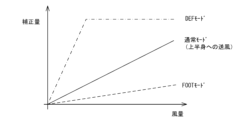
図6は、第2実施形態における風量と補正量との関係を示す図である。
第2実施形態に係る操作装置10では、制御部19が、操作装置10から発信する超音波信号Ωを補正する。そして、この超音波信号Ωへの補正量は、取得したノイズ関連情報に応じて変更する。
Second Embodiment
FIG. 6 is a diagram showing the relationship between the air volume and the correction amount in the second embodiment.
In the
第1実施形態で述べたように、エアコン51の吹出口(51a,51b)は車両100内に複数設けられている。また、送風方向も乗車者の上半身へ送風する通常モード、FOOTモード又はデフロスタモード(DEFモード)等の各種モードによって異なる。
従って、空調風σの超音波通信への影響は、超音波通信時にどのモードが実行されているかに依存する。例えば、FOOTモードでは、空調風σは乗車者の足部を温めるため、車内の床面付近を流れる。よって、エアコン51がFOOTモードで稼働している場合、送風による超音波通信への影響は小さい。
As described in the first embodiment, a plurality of air outlets (51a, 51b) of the
Therefore, the influence of the air conditioning airflow σ on the ultrasonic communication depends on which mode is being executed during ultrasonic communication. For example, in the FOOT mode, the air conditioning airflow σ flows near the floor surface of the vehicle interior to warm the feet of the passengers. Therefore, when the
そこで、例えば図6に示されるように、実行しているモードに合わせて超音波信号Ωへの補正量を変更する。
例えば、図4のルームミラー85の周辺エリア97bに設置された発信装置70が、エアコン51の送風強度及び送風モードに関する情報を、通信ネットワーク90を通じて取得したとする。
このとき、送風モードが上述のFOOTモードの場合、その稼働が超音波通信与える影響は大きくはないと考えられる。よって、発信装置70からエアコン51の送風強度が「強」との情報を受信しても、制御部19における超音波信号Ωの補正量は小さく設定される。つまり、図6に示されるように、風量の増加に伴う超音波信号Ωへの補正量の増加勾配は、各送風モードによって異なるように設定される。
Therefore, for example, as shown in FIG. 6, the amount of correction to the ultrasonic signal Ω is changed in accordance with the mode being executed.
For example, it is assumed that the transmitting
At this time, when the airflow mode is the above-mentioned FOOT mode, it is considered that the operation does not have a large effect on ultrasonic communication. Therefore, even if information is received from the transmitting
なお、図6の一例は車室内の上部に車載マイク72が設けられている場合の風量と補正量との関係を示している。各モードの風量と補正量との関数は、発信装置70の取付位置に応じて変わってくる。補正量は、発信装置70のマイク72と送風している吹出口(51a~51c)との距離、及び空調風σの当たりやすさに応じて、適宜決定される。
The example in Figure 6 shows the relationship between the air volume and the correction amount when the
また、窓センサ94から取得される窓84の開度に合わせて補正量を変更することも好ましい。窓84から流入する外気の流量は、窓84の開度に大きく依存し、また外気は車内に対流を発生させ超音波通信に大きな影響を与えるためである。
このように、超音波信号Ωに補正に、通信ネットワーク90を介して取得される車内機器の稼働状況を加味することで、効果的な補正により通信品質を向上させることができる。
It is also preferable to change the correction amount according to the opening degree of the
In this way, by taking into account the operating status of the in-vehicle devices acquired via the
また、図7は、速度及び加速度と補正量との関係を示すマップである。
第2実施形態では、図7に示される速度及び加速度と補正量とを規定するマップを記憶部14に保持している。このマップは、車両100の超音波に関する特性を各速度及び加速度ごとに測定して、各速度及び加速度ごとに最適な補正量を特定し規定したものである。
FIG. 7 is a map showing the relationship between the speed and acceleration and the correction amount.
In the second embodiment, a map that defines the speed, acceleration, and correction amount shown in Fig. 7 is stored in the
制御部19は、マップ化された補正量に基づいて補正係数の決定し、携帯端末10aから発信される超音波信号Ωを補正する。
例えば、車両100が加速している場合、エンジンが高出力で稼働するため、燃焼音とともにこの燃焼音に含まれる超音波強度も強いと考えられる。よって、加速を強めるに従って、補正量も「小」から「中」、「大」へと増加するように設定される。
The
For example, when the
ところで、コースト時には、フューエルカット中であるため燃焼音はしないため、燃焼音に含まれる超音波などの影響もないと考えられる。しかし、車両100がハイブリッド車の場合、コースト時には電動機による回生音が発生する。回生音については電動車についても同様である。
そこで、コースト時やブレーキ時に発生する回生音を加味して、マップの負の加速エリアの補正量は、電動機の出力に対応させて「中」又は「大」に設定される。
Incidentally, during coasting, there is no combustion noise because fuel is cut off, and it is therefore considered that there is no effect of ultrasonic waves contained in the combustion noise. However, if the
Therefore, taking into consideration the regenerative noise generated during coasting and braking, the correction amount in the negative acceleration area of the map is set to "medium" or "large" according to the output of the electric motor.
なお、発信装置70から送られてくるノイズ関連情報は、通常超音波信号Ωに乗せられるため、超音波帯域での外乱にかき消されて操作装置10に十分に届かない場合がある。この場合、補正量を、過去数分間に受信したノイズ関連情報に基づいて決定してもよい。
Note that since the noise-related information sent from the transmitting
なお、超音波信号Ωを補正することおよびその補正量をノイズ関連情報に基づいて変更すること以外は、第2実施形態は第1実施形態と構成的にも動作的にも同様となるので、重複する説明を省略する。 Note that the second embodiment is similar in configuration and operation to the first embodiment, except for correcting the ultrasonic signal Ω and changing the amount of correction based on noise-related information, so duplicated explanations will be omitted.
このように、第2実施形態に係る操作装置10によれば、第1実施形態の効果に加え、ノイズ環境に応じた補正をすることができるので、車内に外乱が発生していても超音波信号Ωの通信品質を高品質に維持することができる。
In this way, the
(第3実施形態)
図8は、第3実施形態に係る操作装置10の動作を示すフローチャートである。
Third Embodiment
FIG. 8 is a flowchart showing the operation of the operating
第3実施形態に係る操作装置10では、制御部19が、通信品質レベルが所定レベル以下であり、かつ操作装置10の向きが対象車載機器(51~54)に向いていない場合、操作装置10の向きを対象車載機器(51~54)に向けるように報知する。つまり、IVI54が他の対象車載機器(51~53)の中継機になっている場合、IVI54に携帯端末10aを向けるようにユーザ200に報知する。
In the
具体的な手順について、図8のフローチャートを用いて説明する。
まず、情報取得部18は、遠隔操作用アプリケーションの起動を確認し(S21においてYES)、携帯端末10aの向きを確認する(S22)。
携帯端末10aの向きの確認には、携帯端末10aに搭載される電子コンパスを利用する。ユーザ200が着座して携帯端末10aを正しく利用する向きで把持すると、携帯端末10aのスピーカ11は車両100の前方を向くと考えられる。
A specific procedure will be described with reference to the flowchart of FIG.
First, the
The orientation of the
次に、制御部19が、携帯端末10aのスピーカ11の方向と車両100の走行方向が一致するかを確認する(S23)。
車両100の向きは車両100の走行方向の向きと一致するため、走行方向と携帯端末10aの向きが一致した場合(S23においてYES)、携帯端末10aは車両100内で前方を向いていると推定できる。
通常対象車載機器(51~54)は、車室内の前方に配置されることが多い。後部座席53cに設置される場合であっても、ユーザ200より車両進行方向の前側に配置される。よって、車両100の走行向きと携帯端末10aの向きとが一致している場合、携帯端末10aの向きは適切であるといえる。
Next, the
Since the orientation of the
Usually, the target in-vehicle devices (51 to 54) are often arranged at the front of the vehicle interior. Even when they are installed in the
走行方向と携帯端末10aの向きが一致しない場合(S23においてNO)、携帯端末10aが対象車載機器(51~54)に向けられていないと判断する。
そこで、制御部19は携帯端末10aの向きを変更するべき旨を例えば表示部13に表示するにより又は音声によりユーザ200に報知する(S24)。ユーザ200は携帯端末10aの向きを変更して、好適な通信状態を構築できる向きに向ける。
なお、走行方向に一致させる携帯端末10a上の部材は、スピーカ11に限らず、マイク12など機種の特性に応じた適切な部材に設定される。
If the traveling direction and the orientation of the
Therefore, the
The component on the
携帯端末10aのマイク12の方向と車両10の進行方向が一致した場合(S23においてYES)、制御部19は、表示画面26に操作ページ21を表示する等して、一致した旨をユーザ200に報知する(S25)。
なお、近年のスマートフォン10aの多くには、表示方向や縦横比等の表示形態をユーザ200の持ち方に応じて随時変更する機能が標準的に搭載されている。ステップS25における表示形態は、このような技術を応用して、例えば下方を向いたスピーカ11を上方に向かせるように表示画面26中の表示図形を車内の特定方向に固定することで、携帯端末10aを適切な向きに持ち変えさせることをユーザ200に促す表示形態であってもよい。このような表示態様にすることで、ユーザ200は最小の注意力で携帯端末10aの適切な向きを確認し向きを調整することができる。
そして、第1実施形態と同様に通信品質レベルを表示画面26上に表示する(S26;END)。
If the direction of the
In addition, many of the
Then, similarly to the first embodiment, the communication quality level is displayed on the display screen 26 (S26; END).
なお、車両100の進行方向と携帯端末10aの向きを一致させるように促すこと以外は、第3実施形態は第1実施形態と構成的にも動作的にも同様となるので、重複する説明を省略する。
Note that the third embodiment is similar in structure and operation to the first embodiment, except for the prompt to align the direction of travel of the
このように、第3実施形態に係る操作装置10によれば、第1実施形態の効果に加え、ユーザ200が対象車載機器(51~54)の遠隔操作を行う前に向きの調整が促進され好適な通信環境を構築することができる。よって、通信品質レベルを向上させることが可能である。
In this way, according to the
以上述べた少なくとも一つの実施形態の操作装置、発信装置又は通信環境確認プログラムによれば、伝達容易度を可視化することにより、ユーザが超音波通信の通信環境を確認することが可能となる。 According to at least one of the embodiments of the operation device, the transmitting device, or the communication environment confirmation program described above, the ease of transmission is visualized, allowing the user to check the communication environment for ultrasonic communication.
本発明のいくつかの実施形態を説明したが、これらの実施形態は、例として提示したものであり、発明の範囲を限定することは意図していない。
これら実施形態は、その他の様々な形態で実施されることが可能であり、発明の要旨を逸脱しない範囲で、種々の省略、置き換え、変更、組み合わせを行うことができる。
これら実施形態やその変形は、発明の範囲や要旨に含まれると同様に、特許請求の範囲に記載された発明とその均等の範囲に含まれるものである。
Although several embodiments of the present invention have been described, these embodiments are presented as examples and are not intended to limit the scope of the invention.
These embodiments can be implemented in various other forms, and various omissions, substitutions, modifications, and combinations can be made without departing from the spirit of the invention.
These embodiments and their variations are included in the scope of the invention and its equivalents as described in the claims, as well as in the scope and spirit of the invention.
100…車両、200…ユーザ、300…インターネット、400…サーバ、10…遠隔操作装置(操作装置)、10a(10)…携帯端末(スマートフォン)、10b(10)…車内操作端末、11…スピーカ、12…マイク、13…表示部、14…記憶部、15…処理回路、17…送受信部、18…情報取得部、19…制御部、20…入出力部、21…操作ページ、22…タブ、23a~23h,24a~24g…操作ボタン、26…表示画面、27…ステータスバー、28…円弧、29…通信品質レベルを表示するアイコン、31…アイコン、51…エアコンディショナー(エアコン)、51a…前部座席用エアコンの吹出口、51b…後部座席用エアコンの吹出口52…照明、53(53a,53b,53c)…座席シート(運転席,助手席,後部座席)、54…IVI、70…通信環境発信装置(発信装置,IVI)、71…表示部、72…車載マイク(マイク)、73…車載記憶部(記憶部)、74…車載スピーカ、75…車載処理回路(処理回路)、76…検出部、77…位置情報取得部、78…発信部、79…超音波受信部、80…インナーパネル、84…窓、85…ルームミラー、86…ハンドル、90…通信ネットワーク、91…車両制御部(ECU)、92…車速センサ、93…ペダルストロークセンサ、94…窓センサ、95…操舵角センサ、96…GPSセンサ、97a~97c…通信環境発信装置の配置位置、Ω…超音波信号。 100...vehicle, 200...user, 300...Internet, 400...server, 10...remote control device (operation device), 10a (10)...mobile terminal (smartphone), 10b (10)...in-vehicle operation terminal, 11...speaker, 12...microphone, 13...display unit, 14...storage unit, 15...processing circuit, 17...transmission/reception unit, 18...information acquisition unit, 19...control unit, 20...input/output unit, 21...operation page, 22...tab, 23a to 23h, 24a to 24g...operation buttons, 26...display screen, 27...status bar, 28...arc, 29...icon displaying communication quality level, 31...icon, 51...air conditioner (air conditioner), 51a...front seat air conditioner outlet, 51b...rear seat air conditioner outlet 52...illumination 53 (53a, 53b, 53c)...seats (driver's seat, passenger seat, rear seat), 54...IVI, 70...communication environment transmitter (transmitter, IVI), 71...display, 72...vehicle microphone (microphone), 73...vehicle memory (memory), 74...vehicle speaker, 75...vehicle processing circuit (processing circuit), 76...detection unit, 77...position information acquisition unit, 78...transmission unit, 79...ultrasonic receiver, 80...inner panel, 84...window, 85...rearview mirror, 86...steering wheel, 90...communication network, 91...vehicle control unit (ECU), 92...vehicle speed sensor, 93...pedal stroke sensor, 94...window sensor, 95...steering angle sensor, 96...GPS sensor, 97a-97c...position of communication environment transmitter, Ω...ultrasonic signal.
Claims (7)
車両内のノイズ音に関する情報を検出する情報取得部と、
前記情報から前記超音波信号の伝達容易度を算出する制御部と、
算出された前記伝達容易度を前記超音波信号の通信品質レベルとして表示する表示部と、を備えることを特徴とする遠隔操作装置。 a speaker capable of emitting an ultrasonic signal for controlling the operation of an in-vehicle device;
an information acquisition unit that detects information regarding noise sound inside a vehicle;
A control unit that calculates a degree of transmission ease of the ultrasonic signal from the information;
a display unit that displays the calculated ease of transmission as a communication quality level of the ultrasonic signal.
前記制御部は、前記電動機の前記出力に応じて前記超音波信号の補正量を変更する請求項1又は請求項2に記載の遠隔操作装置。 The information acquisition unit detects an output of an electric motor mounted on a vehicle,
3. The remote control device according to claim 1, wherein the control unit changes a correction amount of the ultrasonic signal in accordance with the output of the electric motor.
車両内に設けられて前記超音波通信を阻害しうる前記車両内のノイズ音に関する情報を取得する検出部と、
前記車両内に設けられて前記車両内の前記ノイズ音に関する前記情報を前記遠隔操作装置と前記通信環境発信装置との間の前記超音波通信の伝達容易度を算出するための環境通知信号に変換して前記車両内に配置された前記遠隔操作装置に発信する発信部と、を備えることを特徴とする通信環境発信装置。 A communication environment transmitting device capable of transmitting a signal for controlling an operation of an in-vehicle device from a remote control device via ultrasonic communication , the communication environment transmitting device being capable of receiving the signal via ultrasonic communication ,
a detection unit provided in a vehicle and configured to acquire information regarding noise sound within the vehicle that may impede the ultrasonic communication ;
A communication environment transmitting device characterized by comprising: a transmitting unit provided within the vehicle, which converts the information regarding the noise sound within the vehicle into an environmental notification signal for calculating the transmission ease of the ultrasonic communication between the remote control device and the communication environment transmitting device, and transmits the information to the remote control device provided within the vehicle.
車両内のノイズ音に関する情報を受信するステップ、
前記情報から前記超音波信号の伝達容易度を算出するステップ、
算出された前記伝達容易度を前記超音波信号の通信品質レベルとして表示するステップ、を実行させることを特徴とする通信環境確認プログラム。 A computer that controls the operation of in-vehicle equipment using ultrasonic signals.
receiving information regarding a noise sound within the vehicle;
calculating a transmission ease of the ultrasonic signal from the information;
and displaying the calculated degree of ease of transmission as a communication quality level of the ultrasonic signal.
Priority Applications (3)
| Application Number | Priority Date | Filing Date | Title |
|---|---|---|---|
| JP2020212383A JP7619040B2 (en) | 2020-12-22 | 2020-12-22 | Remote control device, communication environment transmission device, and communication environment confirmation program |
| HUE21197317A HUE068960T2 (en) | 2020-12-22 | 2021-09-17 | Remote controller, communication-environment sending device, and communication-environment check method |
| EP21197317.7A EP4020850B1 (en) | 2020-12-22 | 2021-09-17 | Remote controller, communication-environment sending device, and communication-environment check method |
Applications Claiming Priority (1)
| Application Number | Priority Date | Filing Date | Title |
|---|---|---|---|
| JP2020212383A JP7619040B2 (en) | 2020-12-22 | 2020-12-22 | Remote control device, communication environment transmission device, and communication environment confirmation program |
Publications (2)
| Publication Number | Publication Date |
|---|---|
| JP2022098789A JP2022098789A (en) | 2022-07-04 |
| JP7619040B2 true JP7619040B2 (en) | 2025-01-22 |
Family
ID=78293844
Family Applications (1)
| Application Number | Title | Priority Date | Filing Date |
|---|---|---|---|
| JP2020212383A Active JP7619040B2 (en) | 2020-12-22 | 2020-12-22 | Remote control device, communication environment transmission device, and communication environment confirmation program |
Country Status (3)
| Country | Link |
|---|---|
| EP (1) | EP4020850B1 (en) |
| JP (1) | JP7619040B2 (en) |
| HU (1) | HUE068960T2 (en) |
Families Citing this family (1)
| Publication number | Priority date | Publication date | Assignee | Title |
|---|---|---|---|---|
| KR20250037315A (en) * | 2023-09-08 | 2025-03-17 | 상하이 토선 테크놀로지 리미티드 | Method, server, request unit, and response unit for multi-region cooperative remote calibration of vehicle |
Citations (6)
| Publication number | Priority date | Publication date | Assignee | Title |
|---|---|---|---|---|
| JP2001078276A (en) | 1999-09-07 | 2001-03-23 | Mitsubishi Electric Corp | Remote control device |
| JP2003324498A (en) | 2002-05-08 | 2003-11-14 | Chuo Spring Co Ltd | Wireless transmitting / receiving system and opening / closing device for building opening |
| JP2004336261A (en) | 2003-05-06 | 2004-11-25 | Funai Electric Co Ltd | Remote control system, and disk device |
| JP2013238184A (en) | 2012-05-16 | 2013-11-28 | Denso Corp | Remote engine starter and on-vehicle machine |
| JP2018034642A (en) | 2016-08-31 | 2018-03-08 | ヤマハ株式会社 | Cabin sound environment notification device and cabin sound environment notification method |
| WO2019077594A1 (en) | 2017-10-16 | 2019-04-25 | Sonular Ltd. | Communication management and communicating between a communication device and another device |
Family Cites Families (3)
| Publication number | Priority date | Publication date | Assignee | Title |
|---|---|---|---|---|
| US20150243163A1 (en) * | 2012-12-14 | 2015-08-27 | Biscotti Inc. | Audio Based Remote Control Functionality |
| JP6079532B2 (en) | 2013-09-26 | 2017-02-15 | トヨタ自動車株式会社 | Vehicle authentication device |
| KR101675364B1 (en) * | 2015-05-21 | 2016-11-22 | 주식회사 엠투브 | Pairing method with obd terminal for vehicle using beacon and the obd terminal for vehicle |
-
2020
- 2020-12-22 JP JP2020212383A patent/JP7619040B2/en active Active
-
2021
- 2021-09-17 HU HUE21197317A patent/HUE068960T2/en unknown
- 2021-09-17 EP EP21197317.7A patent/EP4020850B1/en active Active
Patent Citations (6)
| Publication number | Priority date | Publication date | Assignee | Title |
|---|---|---|---|---|
| JP2001078276A (en) | 1999-09-07 | 2001-03-23 | Mitsubishi Electric Corp | Remote control device |
| JP2003324498A (en) | 2002-05-08 | 2003-11-14 | Chuo Spring Co Ltd | Wireless transmitting / receiving system and opening / closing device for building opening |
| JP2004336261A (en) | 2003-05-06 | 2004-11-25 | Funai Electric Co Ltd | Remote control system, and disk device |
| JP2013238184A (en) | 2012-05-16 | 2013-11-28 | Denso Corp | Remote engine starter and on-vehicle machine |
| JP2018034642A (en) | 2016-08-31 | 2018-03-08 | ヤマハ株式会社 | Cabin sound environment notification device and cabin sound environment notification method |
| WO2019077594A1 (en) | 2017-10-16 | 2019-04-25 | Sonular Ltd. | Communication management and communicating between a communication device and another device |
Also Published As
| Publication number | Publication date |
|---|---|
| JP2022098789A (en) | 2022-07-04 |
| EP4020850A1 (en) | 2022-06-29 |
| EP4020850B1 (en) | 2024-08-21 |
| HUE068960T2 (en) | 2025-02-28 |
Similar Documents
| Publication | Publication Date | Title |
|---|---|---|
| EP3121064B1 (en) | Vehicle control device and vehicle control method thereof | |
| US10852720B2 (en) | Systems and methods for vehicle assistance | |
| US9327645B2 (en) | Providing alerts for objects left in a vehicle | |
| US10606378B2 (en) | Dynamic reconfigurable display knobs | |
| US10318828B2 (en) | Vehicle behavior analysis | |
| US11150729B2 (en) | Off-axis gaze tracking in in-vehicle computing systems | |
| US8854229B2 (en) | Apparatus for warning pedestrians of oncoming vehicle | |
| US20180226077A1 (en) | Vehicle driving assist and vehicle having same | |
| KR102931644B1 (en) | Voice control of vehicle systems | |
| US11190155B2 (en) | Learning auxiliary feature preferences and controlling the auxiliary devices based thereon | |
| JP2015128988A (en) | Automatic driver identification | |
| JP2015129753A (en) | Scheduling notifications in the car | |
| CN104346199A (en) | System and methods for an in-vehicle computing system | |
| CN113581071A (en) | System and method for external environment sensing and rendering | |
| CN118797715A (en) | System and method for protecting private user data based on GPS | |
| KR101487474B1 (en) | Simulation sound generation apparatus of vehicle and simulation sound generation method of vehicle using the same | |
| JP7619040B2 (en) | Remote control device, communication environment transmission device, and communication environment confirmation program | |
| JP7732182B2 (en) | Communication environment transmission device and communication environment transmission program | |
| JP7647094B2 (en) | Remote Control Device | |
| JP2009126465A (en) | Electronic control unit cooling system |
Legal Events
| Date | Code | Title | Description |
|---|---|---|---|
| A621 | Written request for application examination |
Free format text: JAPANESE INTERMEDIATE CODE: A621 Effective date: 20230925 |
|
| A977 | Report on retrieval |
Free format text: JAPANESE INTERMEDIATE CODE: A971007 Effective date: 20240814 |
|
| A131 | Notification of reasons for refusal |
Free format text: JAPANESE INTERMEDIATE CODE: A131 Effective date: 20240820 |
|
| A521 | Request for written amendment filed |
Free format text: JAPANESE INTERMEDIATE CODE: A523 Effective date: 20240911 |
|
| A131 | Notification of reasons for refusal |
Free format text: JAPANESE INTERMEDIATE CODE: A131 Effective date: 20241105 |
|
| A521 | Request for written amendment filed |
Free format text: JAPANESE INTERMEDIATE CODE: A523 Effective date: 20241127 |
|
| TRDD | Decision of grant or rejection written | ||
| A01 | Written decision to grant a patent or to grant a registration (utility model) |
Free format text: JAPANESE INTERMEDIATE CODE: A01 Effective date: 20241210 |
|
| A61 | First payment of annual fees (during grant procedure) |
Free format text: JAPANESE INTERMEDIATE CODE: A61 Effective date: 20241223 |
|
| R150 | Certificate of patent or registration of utility model |
Ref document number: 7619040 Country of ref document: JP Free format text: JAPANESE INTERMEDIATE CODE: R150 |