JP7620009B2 - Hydraulic tool device head - Google Patents
Hydraulic tool device head Download PDFInfo
- Publication number
- JP7620009B2 JP7620009B2 JP2022520520A JP2022520520A JP7620009B2 JP 7620009 B2 JP7620009 B2 JP 7620009B2 JP 2022520520 A JP2022520520 A JP 2022520520A JP 2022520520 A JP2022520520 A JP 2022520520A JP 7620009 B2 JP7620009 B2 JP 7620009B2
- Authority
- JP
- Japan
- Prior art keywords
- device head
- tool
- piston
- hydraulic
- cylindrical structure
- Prior art date
- Legal status (The legal status is an assumption and is not a legal conclusion. Google has not performed a legal analysis and makes no representation as to the accuracy of the status listed.)
- Active
Links
Images


Classifications
-
- B—PERFORMING OPERATIONS; TRANSPORTING
- B21—MECHANICAL METAL-WORKING WITHOUT ESSENTIALLY REMOVING MATERIAL; PUNCHING METAL
- B21D—WORKING OR PROCESSING OF SHEET METAL OR METAL TUBES, RODS OR PROFILES WITHOUT ESSENTIALLY REMOVING MATERIAL; PUNCHING METAL
- B21D39/00—Application of procedures in order to connect objects or parts, e.g. coating with sheet metal otherwise than by plating; Tube expanders
- B21D39/04—Application of procedures in order to connect objects or parts, e.g. coating with sheet metal otherwise than by plating; Tube expanders of tubes with tubes; of tubes with rods
- B21D39/048—Application of procedures in order to connect objects or parts, e.g. coating with sheet metal otherwise than by plating; Tube expanders of tubes with tubes; of tubes with rods using presses for radially crimping tubular elements
-
- B—PERFORMING OPERATIONS; TRANSPORTING
- B25—HAND TOOLS; PORTABLE POWER-DRIVEN TOOLS; MANIPULATORS
- B25B—TOOLS OR BENCH DEVICES NOT OTHERWISE PROVIDED FOR, FOR FASTENING, CONNECTING, DISENGAGING, OR HOLDING
- B25B27/00—Hand tools, specially adapted for fitting together or separating parts or objects whether or not involving some deformation, not otherwise provided for
- B25B27/02—Hand tools, specially adapted for fitting together or separating parts or objects whether or not involving some deformation, not otherwise provided for for connecting objects by press fit or detaching same
- B25B27/10—Hand tools, specially adapted for fitting together or separating parts or objects whether or not involving some deformation, not otherwise provided for for connecting objects by press fit or detaching same inserting fittings into hoses
-
- B—PERFORMING OPERATIONS; TRANSPORTING
- B25—HAND TOOLS; PORTABLE POWER-DRIVEN TOOLS; MANIPULATORS
- B25B—TOOLS OR BENCH DEVICES NOT OTHERWISE PROVIDED FOR, FOR FASTENING, CONNECTING, DISENGAGING, OR HOLDING
- B25B27/00—Hand tools, specially adapted for fitting together or separating parts or objects whether or not involving some deformation, not otherwise provided for
- B25B27/14—Hand tools, specially adapted for fitting together or separating parts or objects whether or not involving some deformation, not otherwise provided for for assembling objects other than by press fit or detaching same
- B25B27/146—Clip clamping hand tools
-
- B—PERFORMING OPERATIONS; TRANSPORTING
- B25—HAND TOOLS; PORTABLE POWER-DRIVEN TOOLS; MANIPULATORS
- B25F—COMBINATION OR MULTI-PURPOSE TOOLS NOT OTHERWISE PROVIDED FOR; DETAILS OR COMPONENTS OF PORTABLE POWER-DRIVEN TOOLS NOT PARTICULARLY RELATED TO THE OPERATIONS PERFORMED AND NOT OTHERWISE PROVIDED FOR
- B25F5/00—Details or components of portable power-driven tools not particularly related to the operations performed and not otherwise provided for
- B25F5/005—Hydraulic driving means
-
- B—PERFORMING OPERATIONS; TRANSPORTING
- B25—HAND TOOLS; PORTABLE POWER-DRIVEN TOOLS; MANIPULATORS
- B25F—COMBINATION OR MULTI-PURPOSE TOOLS NOT OTHERWISE PROVIDED FOR; DETAILS OR COMPONENTS OF PORTABLE POWER-DRIVEN TOOLS NOT PARTICULARLY RELATED TO THE OPERATIONS PERFORMED AND NOT OTHERWISE PROVIDED FOR
- B25F5/00—Details or components of portable power-driven tools not particularly related to the operations performed and not otherwise provided for
- B25F5/02—Construction of casings, bodies or handles
-
- H—ELECTRICITY
- H01—ELECTRIC ELEMENTS
- H01R—ELECTRICALLY-CONDUCTIVE CONNECTIONS; STRUCTURAL ASSOCIATIONS OF A PLURALITY OF MUTUALLY-INSULATED ELECTRICAL CONNECTING ELEMENTS; COUPLING DEVICES; CURRENT COLLECTORS
- H01R43/00—Apparatus or processes specially adapted for manufacturing, assembling, maintaining, or repairing of line connectors or current collectors or for joining electric conductors
- H01R43/04—Apparatus or processes specially adapted for manufacturing, assembling, maintaining, or repairing of line connectors or current collectors or for joining electric conductors for forming connections by deformation, e.g. crimping tool
- H01R43/042—Hand tools for crimping
-
- B—PERFORMING OPERATIONS; TRANSPORTING
- B25—HAND TOOLS; PORTABLE POWER-DRIVEN TOOLS; MANIPULATORS
- B25B—TOOLS OR BENCH DEVICES NOT OTHERWISE PROVIDED FOR, FOR FASTENING, CONNECTING, DISENGAGING, OR HOLDING
- B25B27/00—Hand tools, specially adapted for fitting together or separating parts or objects whether or not involving some deformation, not otherwise provided for
- B25B27/02—Hand tools, specially adapted for fitting together or separating parts or objects whether or not involving some deformation, not otherwise provided for for connecting objects by press fit or detaching same
- B25B27/026—Hand tools, specially adapted for fitting together or separating parts or objects whether or not involving some deformation, not otherwise provided for for connecting objects by press fit or detaching same fluid driven
Landscapes
- Engineering & Computer Science (AREA)
- Mechanical Engineering (AREA)
- Manufacturing & Machinery (AREA)
- Actuator (AREA)
- Earth Drilling (AREA)
- Portable Power Tools In General (AREA)
- Hand Tools For Fitting Together And Separating, Or Other Hand Tools (AREA)
Description
本発明は、請求項1の前段部分に記載の油圧作動ツールのデバイスヘッドに関する。 The present invention relates to a device head for a hydraulically actuated tool as described in the opening part of claim 1.
課題における類型のデバイスヘッドは、様々な実施形態で知られている。油圧駆動を伴う組み合わせにおいて、それらは例えばワークピースのプレス、切削、または孔開けに供され、これらの目的のために、対応する第1及び第2ツールがデバイスヘッドにまたは油圧ピストンに配置されている。例えば特許文献1が参照される。 Device heads of the type in question are known in various embodiments. In combination with hydraulic drive, they serve, for example, to press, cut or drill workpieces, and for these purposes corresponding first and second tools are arranged in the device head or on the hydraulic piston. See, for example, US Pat. No. 5,399,433.
さらに基本的に一体的に一部品として及び同一素材でデバイスヘッドを形成することが知られており、そうしてそれが一体的に一部品であるカウンタホルダと、直接または非直接に油圧シリンダを収容し誘導するためのシリンダ形構造体とを有する。
特許文献3によるデバイスヘッドが公知であり、その場合の第2ツール担持体は、デバイスヘッドの長さにわたって異なった直径であるが常に円形に形成される。しかしながらその取り外しもまた、底部に対してのみ可能である。
It is further known to form a device head essentially as one integral part and of the same material, which thus has a counterholder which is one integral part and a cylindrical structure for receiving and guiding, directly or indirectly, a hydraulic cylinder.
A device head is known from
本目的は、油圧ピストンによって移動可能で、操作に関してより改良された第2ツールを有する、課題における類型のデバイスヘッドを設計することである。The aim is to design a device head of the type in question, which has a second tool movable by a hydraulic piston and which is more improved in terms of manipulation.
この目的は請求項1の主題により解決され、それによる焦点は、第2ツール担持体が油圧ピストンの軸に対して横方向の断面に関して引き延ばされた長方形の態様で形成され、使用状態において垂直に延びる長手方向の外縁が引き延ばされた長方形の態様で形成され、一方でそれに対して横方向にみられる短手方向の外縁の各々が、曲線に沿って誘導され、かつこの曲線がその軸に関して共通の半径を有し、その場合、半径の寸法がシリンダ形構造体における周囲のジャケット壁の直径の寸法に適合することにある。This object is solved by the subject matter of claim 1, whereby the focus is on the fact that the second tool carrier is formed in the manner of an elongated rectangle in a cross section transverse to the axis of the hydraulic piston, and that in the use state the longitudinal outer edges extending perpendicularly thereto are formed in the manner of an elongated rectangle, while the transversely thereto, transversely thereto, each of the transverse outer edges is guided along a curve and this curve has a common radius in relation to its axis, the dimensions of the radius being adapted to the dimensions of the diameter of the surrounding jacket wall in a cylindrical structure.
動作終点は、それゆえに強制的なものではなく、選択的に停止制限される、油圧ピストンの最大で到達しうる終点でなければならない。対照的に、動作終点は油圧ピストンの変位位置になり得、明細書に沿ってツールを使用し、実施される手段を実施する。この到達した動作終点から、油圧システムにおいて実行されたバルブ開放の結果として選択的に自動的に、油圧ピストンは初期位置の方向に動く。 The end point of operation is therefore not mandatory but must be the maximum reachable end point of the hydraulic piston, selectively limited. In contrast, the end point of operation can be a displacement position of the hydraulic piston, using the tool and implementing the means according to the specification. From this reached end point of operation, the hydraulic piston moves in the direction of the initial position, selectively automatically as a result of a valve opening implemented in the hydraulic system.
第2ツールのための受容器は、ピストンシャフトと一部品として、さらに好ましくはピストンシャフトと同一の素材により形成される。これはさらに製造と組立に関連した有利性を提供する。 The receptacle for the second tool is formed in one piece with the piston shaft and preferably from the same material as the piston shaft, which further offers advantages in relation to manufacture and assembly.
従って油圧ピストンをさらに好ましくは、ピストンシャフトに接続されないように、または代わりにピストンシャフトに分離可能に接続されるように、設置することができる。 The hydraulic piston may therefore further preferably be arranged so as not to be connected to the piston shaft, or alternatively so as to be detachably connected to the piston shaft.
シリンダ形構造体へのピストンシャフトの完全な収容によって、それが初期位置にあることによっても、ピストンシャフトが、例えばデバイスヘッドの交換時またはデバイスヘッドの収納時に、外部からの直接的な損傷から保護される。 The complete containment of the piston shaft in the cylindrical structure, even when it is in the initial position, protects the piston shaft from direct external damage, for example when exchanging the device head or when storing the device head.
ピストンシャフトを備えるツール容器の取り外しは、有利な手段において、デバイスヘッドのカウンタホルダとシリンダ形構造体の間に残るデバイス顎部を通ることで、可能である。 Removal of the tool container with the piston shaft is possible in an advantageous manner through the device jaws which remain between the counter holder of the device head and the cylindrical structure.
デバイスヘッドは、角度固定であるが変更可能な保持ロッドの配置のために一体的に一部品としての歯形凹部をさらに有することができる。 The device head may further include an integral, one-piece tooth-shaped recess for angularly fixed but variable placement of a retaining rod.
例えば、本体から離れた使用者によるデバイスヘッドの使用は、そのような保持ロッドを使用することにより可能となる。加えてまたは代わりに、デバイスヘッドは保持ロッドを使用することによって作動位置に固定される。少なくとも例えば1メーター以上の距離でのすべての実施例における例えば頭上での作動は、保持ロッドを用いることで可能となり得る。とりわけデバイスヘッドは、ただし選択的に油圧シリンダに対して作用する油圧ユニットもまた、それによりもはや直接にまたは手のみにより保持されず、しかし逆に、追加的ないずれの実施例においても、保持ロッドにより保持される。 For example, use of the device head by a user away from the main body is possible by using such a holding rod. Additionally or alternatively, the device head is fixed in an operating position by using a holding rod. Operation, for example overhead, in all embodiments at least at a distance of, for example, one meter or more may be possible by using a holding rod. In particular, the device head, but also the hydraulic unit selectively acting on the hydraulic cylinder, is thereby no longer held directly or only by hand, but on the contrary, in any additional embodiment, by a holding rod.
保持ロッドは、例えば0.5メートル、1メートル、2メートル、例えば3メートルまでの固定長を有しうる。従ってそれぞれの中間の長さを、例えば0.5から3メートルの間で、固定長として与えることも可能である。可能な設計において、保持ロッドをその長さに関して例えば伸縮自在の実施形態の結果として、0.5から2メートル伸縮可能な長さで、設定可能な手段において形成することもできる。 The holding rods can have a fixed length, for example 0.5 meters, 1 meter, 2 meters, for example up to 3 meters. It is therefore also possible to provide the respective intermediate lengths as fixed lengths, for example between 0.5 and 3 meters. In a possible design, the holding rods can also be formed in a configurable manner with a length that is extendable with respect to their length, for example between 0.5 and 2 meters, as a result of an embodiment that is extendable.
保持ロッドを介した操作は、デバイスヘッドに設けられた歯形の外面成形の結果として、促進される。これはデバイスヘッドの長手方向の中心軸に関して保持ロッドの角度固定された配置を提供する。この長手方向中心軸は、選択的に同時に油圧シリンダまたは油圧ピストンそれぞれの回転軸を支えることができる。この保持ロッドの角度の配置を、好ましくは変更することができ、この目的のために、歯形凹部により提供される完全な接続を一時的に解消することができる。 Manipulation via the retaining rod is facilitated as a result of the external shaping of the tooth profile provided on the device head, which provides an angularly fixed arrangement of the retaining rod with respect to the longitudinal central axis of the device head, which can selectively simultaneously support the axis of rotation of the hydraulic cylinder or hydraulic piston, respectively. The angular arrangement of the retaining rod can preferably be changed, and for this purpose the complete connection provided by the tooth profile recess can be temporarily eliminated.
一体的に一部品として形成される歯形凹部は、デバイスヘッドの外周面に対して持ち上がった歯形凸部を有することができ、選択的に1つだけそのような歯形凸部を有することができ、またはデバイスヘッドの上述の面に対して後退した歯形凹部である場合に、選択的に1つだけ歯形凹部を有することができる。 A tooth-shaped recess formed integrally as one piece can have a tooth-shaped protrusion raised relative to the outer peripheral surface of the device head, and can optionally have only one such tooth-shaped protrusion, or can optionally have only one tooth-shaped recess if the tooth-shaped recess is recessed relative to the aforementioned surface of the device head.
第2ツールが初期位置と動作終点との間を油圧ピストンによって移動することができ、そこでピストンシャフトが受容部を有してその受容部がピストンシャフトに比して油圧ピストンの動作方向に対して横方向に拡大されかつ第2ツールに割り当てられ、そして動作終点において受容部がデバイスヘッドに形成される下方切り欠き部における動作方向に対して横方向に保持される。 The second tool can be moved by the hydraulic piston between an initial position and an end point of operation, in which the piston shaft has a receiving portion which is enlarged transversely to the direction of operation of the hydraulic piston compared to the piston shaft and which is assigned to the second tool , and in which at the end point of operation the receiving portion is held transversely to the direction of operation in a lower cutout formed in the device head .
ピストンシャフトによって動作方向に変位可能な受容部は、第2ツールを保持するために、好ましくは交換可能な第2ツールを保持するために形成される。これによりこの受容部は、少なくとも移動方向に対し横方向においてピストンシャフトのジャケット表面を越えて延在する。そこでピストンシャフトと比較した受容部の拡大は、この点について、少なくとも、ピストンシャフトの長手方向の軸についてみられるピストンシャフトの周囲の一部分にわたって与えられることができる。さらに、動作方向に向いたピストンシャフトの長手方向の軸に関し、基本的に直径方向に位置する拡大された部分は、このように第2ツールのための受容部を形成することができる。ピストンシャフトの周囲全体にわたって、受容部がさらに、例えばそのジャケット表面を越えて延在することもできる。 The receptacle displaceable in the operating direction by the piston shaft is formed for holding a second tool , preferably a replaceable second tool, whereby this receptacle extends beyond the jacket surface of the piston shaft at least transversely to the direction of movement. The enlargement of the receptacle compared to the piston shaft can in this respect be provided at least over a portion of the circumference of the piston shaft seen with respect to the longitudinal axis of the piston shaft. Furthermore, an enlarged portion that is essentially located diametrically with respect to the longitudinal axis of the piston shaft oriented in the operating direction can thus form a receptacle for the second tool. Over the entire circumference of the piston shaft, the receptacle can also extend further, for example beyond its jacket surface.
相対的に大きな力が、特に第2ツールのための受容部に対して、特に動作終点において、さらに選択的に初期位置と動作終点の間の中間位置においても、働く。ここで第2ツールを備えた受容部の起こり得る傾きに対抗するために、その受容部は下方切り欠き部において保持される。この下方切り欠き部は好ましくは第2ツールのための受容部の動作方向に対して横方向に作用する。それによって、改良された動作結果、例えばプレスや切削結果が、有利な態様で達成され得る。 A relatively large force acts, in particular on the receptacle for the second tool, in particular at the end of the movement, and optionally also in intermediate positions between the initial position and the end of the movement. In order to counteract a possible tilt of the receptacle with the second tool, the receptacle is held in a lower cutout, which preferably acts transversely to the direction of movement of the receptacle for the second tool. Improved operating results, for example pressing or cutting results, can thereby be achieved in an advantageous manner.
下方切り欠き部の形成のために、受容部は例えば、デバイスヘッドの重なり合う部分により受容部の動作方向に対して横方向において重なり合う突出領域を有することができる。代替として、受容部は、アンダーラップ部分と、このように連携するデバイスヘッド突出領域も有することができる。とりわけ受容部は、さらに選択的には受容部に接続されたピストンシャフトもまた、動作方向に対して横方向への移動阻止だけでなく、とりわけ動作終点において、それによって誘導される。 Due to the formation of the lower cutout, the receiving part can have, for example, a protruding area that overlaps with the overlapping part of the device head in a direction transverse to the direction of movement of the receiving part. Alternatively, the receiving part can also have an underlap part and a device head protruding area that cooperates in this way. In particular, the receiving part, and optionally also the piston shaft connected to the receiving part, is not only prevented from moving transversely to the direction of movement, but is also guided thereby, in particular at the end of the movement.
デバイスヘッドの長手方向の断面図でみられるように、その長手方向断面図において、油圧ピストンの回転軸は直線として示される。歯形凹部をシリンダ形構造体から側面側に離れるようにただしそれと重なり合うように形成できる。従ってその重なり合いは、油圧ピストンの軸に関し半径方向において生じる。その重なり合いは、さらにピストンシャフト領域において生じ、さらに選択的に油圧ピストンの動作終点だけでなく初期位置においても生じる。 As seen in the longitudinal section of the device head, in the longitudinal section the axis of rotation of the hydraulic piston is shown as a straight line. The tooth recesses can be formed laterally away from the cylindrical structure but overlapping it. The overlapping therefore occurs in the radial direction with respect to the axis of the hydraulic piston. The overlapping also occurs in the piston shaft area and optionally also in the initial position as well as at the end of the hydraulic piston's motion.
歯形凹部の領域において、シリンダ形構造体は、脚部へと移行することができる。その脚部は、シリンダ形構造体と一体的かつ一部品となるシリンダ形構造体の直径の長さと比較して、小さな厚みで成形される。延長部において、この脚部はさらに油圧ピストンの軸と基本的に同じ方向にカウンタホルダを担持することができる。 In the region of the toothed recess, the cylindrical structure can transition into a leg, which is molded with a small thickness compared to the length of the diameter of the cylindrical structure, which is integral and in one piece with the cylindrical structure. In its extension, this leg can further carry a counterholder in essentially the same direction as the axis of the hydraulic piston.
中央の貫通孔に関して、例えばクランピング手段、さらに例えばクランピングスクリューの貫通のために、歯形凹部を同心円状に円周状に形成することができる。仮にいくつかの歯形凸部または歯形凹部の歯形くぼみが設けられる場合には、それらは好ましくは貫通孔の幾何学的中心軸に関し、円形または弓形状に全体として位置付けられる。 With respect to the central through-hole, tooth recesses can be formed concentrically and circumferentially, for example for the passage of clamping means, further for example clamping screws. If several tooth projections or tooth recesses are provided, they are preferably positioned as a whole in a circular or arcuate manner with respect to the geometric central axis of the through-hole.
いくつかの歯形凸部または歯形凹部の歯形くぼみの配置の実施例において、それらは貫通孔の幾何学的中心軸を基準に円周方向に相互に均一に離れて位置するように、設けることもできる。 In an embodiment where the tooth projections or recesses of the tooth recesses are arranged in a number of ways, they may be arranged so that they are uniformly spaced apart from one another in the circumferential direction with respect to the geometric central axis of the through hole.
第2ツールのための受容部を、好ましくはピストンシャフトと一部品として、さらに好ましくは同一の素材で、形成することができ、ピストンシャフトに対して油圧ピストンが好ましくは作用し得る。これはさらに製造と組立に関する有利性を提示する。さらに好ましくは、それにより油圧ピストンが、ピストンシャフトと接続されないように、または代替としてピストンシャフトと分離可能に接続するように、設けることができる。 The receiver for the second tool can preferably be formed in one piece with the piston shaft, more preferably from the same material, on which the hydraulic piston can preferably act. This offers further advantages in terms of manufacturing and assembly. More preferably, the hydraulic piston can thereby be provided in such a way that it is not connected to the piston shaft, or alternatively is separably connected to the piston shaft.
この設計の結果として、受容部は、ピストンシャフトとともに、組立の過程で一部品構成においてデバイスヘッド内に挿入されることができ、または分解の過程でデバイスヘッドから取り外すことができる。 As a result of this design, the receiver, together with the piston shaft, can be inserted into the device head in one piece during assembly or removed from the device head during disassembly.
この目的のために、油圧ピストンによる負荷がかからないデバイスヘッドの基準位置に好ましくは対応させることができる初期位置において、受容部はさらに、組立及び分解のために、移動方向に対して横方向に変位可能であることができる。これはさらに特に、デバイスヘッドに、好ましくは動作終点に設けられる下方切り欠き部が、設けられないか、または初期位置において克服されることで達成され得る。好ましい設計において、この下方切り欠き部とそれにより生じる誘導は、回転と傾きに対する防止と同様に、初期位置から動作終点の方向へ受容部が変位するときにのみ達成される。 For this purpose, in the initial position, which can preferably correspond to the reference position of the device head without the load of the hydraulic piston, the receiving part can furthermore be displaceable transversely to the direction of movement for assembly and disassembly. This can be achieved more particularly in that a lower cutout provided on the device head, preferably at the end of the movement, is not provided or is overcome in the initial position. In a preferred design, this lower cutout and the resulting guidance, as well as the protection against rotation and tilting, are achieved only when the receiving part is displaced from the initial position in the direction of the end of the movement.
それによって可能となる、動作方向に対して横方向の受容部の変位可能性により、とりわけピストンシャフトと一部品として形成される受容部の、好ましい組立または分解がそれぞれ可能となる。それは組立部品の際に傾斜を可能とした結果として、前記受容部がシリンダ形構造体内へ移動可能になり、または分解中にシリンダ形構造体の外に移動することがそれぞれできることで、可能となる。 The thereby possible displaceability of the receiving part transversely to the direction of movement allows for a favorable assembly or disassembly, respectively, of the receiving part which is formed in one piece with the piston shaft, since as a result of the tilting possible during assembly, said receiving part can be moved into the cylindrical structure or out of the cylindrical structure during disassembly, respectively.
さらなる設計において、デバイスヘッドを油圧ホースに接続可能であり、油圧ホースは、油圧を発生させる油圧ユニットに比較してデバイスヘッドの自由な可動性のために、他端で油圧ユニットに接続することができる。油圧ホースはそれにより、おおむね自由にデバイスヘッドを動かすことを許容する長さを有することができ、一方で油圧ユニットは好ましくは床の上にまたは例えばテーブルの高さに置かれる。保持ロッドのその配置は、とりわけそのような形態の実施例に適している。この形態は、例えばデバイスヘッドの頭上での使用、さらに好ましくは、使用者から例えば1から2メートルまたはそれ以上の距離で行われる使用を許容する。 In a further design, the device head can be connected to a hydraulic hose, which can be connected at the other end to a hydraulic unit for free mobility of the device head compared to the hydraulic unit generating the hydraulic pressure. The hydraulic hose can thereby have a length that allows for more or less free movement of the device head, while the hydraulic unit is preferably placed on the floor or, for example, at table height. That arrangement of the holding rod is particularly suitable for such a configuration embodiment. This configuration allows, for example, an overhead use of the device head, and even more preferably, a use that takes place at a distance of, for example, 1 to 2 meters or more from the user.
デバイスヘッドを固く接続することができる本体キャスティングツール部は、例えば特許文献2により公知である。当該特許の明細書の内容は、本発明の請求項において当該特許の特徴が含まれる目的においても、その全体が本発明の開示に含まれるものとする。 A main body casting tool part to which a device head can be firmly connected is known, for example, from US Pat. No. 5,399,363. The contents of the specification of that patent are included in their entirety in the disclosure of the present invention, also for the purpose of including the features of that patent in the claims of the present invention.
本体キャスティングツール部は同時に、使用者によってデバイスヘッドを誘導するためのハンドルとして使用することができる。その本体キャスティングツール部の配置において、保持ロッドの配置またはデバイスヘッドに配置された保持ロッドの使用はそれぞれなしで済ますことができる。しかしながら、設置された保持ロッドによりデバイスヘッドと本体キャスティングツール部との固く接続された配置を、任意で追加的に保持することまたは誘導することをもそれぞれ可能とする。 The main casting tool part can simultaneously be used as a handle for guiding the device head by the user. In the positioning of the main casting tool part, the positioning of a holding rod or the use of a holding rod arranged on the device head, respectively, can be dispensed with. However, the installed holding rod also allows for an optional additional holding or guiding of the firmly connected arrangement of the device head and the main casting tool part, respectively.
その場合、初期位置において油圧ピストンをシリンダ形構造体に完全に収容することができる。油圧ピストンまたは油圧ピストンの一部はこのように軸方向において、好ましくはシリンダ形構造体を、選択的にそれによって形成される油圧シリンダを、越えて突出しない。このことは、例えばデバイスヘッドの交換またはデバイスヘッドの保管の際に、例えばデバイスヘッドが油圧ホースまたは本体キャスティングツール部に連結していないという有利性を提供する。シリンダ形構造体の一端を越えて自由に突出する結果として油圧ピストンまたは油圧ピストンの部分への損傷は、本発明における設計により避けられる。 In that case, in the initial position, the hydraulic piston can be completely accommodated in the cylindrical structure. The hydraulic piston or parts of the hydraulic piston thus do not protrude axially, preferably beyond the cylindrical structure, optionally beyond the hydraulic cylinder formed thereby. This provides the advantage that, for example, when exchanging the device head or storing the device head, the device head is not connected to hydraulic hoses or to the main casting tool part. Damage to the hydraulic piston or parts of the hydraulic piston as a result of freely protruding beyond one end of the cylindrical structure is avoided by the design according to the invention.
シリンダ形構造体は、油圧ピストンの初期位置を基準とした油圧ピストンを取り囲む領域の外側であって、動作終点から初期位置への油圧ピストンの動作方向の延長上、または油圧ピストンの回転軸の延長方向に、本体キャスティングツール部または油圧ホースのための連結レセプタクルを有することもできる。このようにその連結レセプタクルは、油圧ピストンの軸方向または動作方向のそれぞれにおいて、好ましくは初期位置や動作終点だけでなくこれら二つの端点の間におけるすべての位置においても、油圧ピストンから離れて位置する。これがさらなる組立に関する有利性を提供する。 The cylindrical structure may also have a connection receptacle for a main casting tool part or a hydraulic hose outside the area surrounding the hydraulic piston relative to the initial position of the hydraulic piston, in the extension of the direction of motion of the hydraulic piston from the end point of motion to the initial position, or in the extension of the axis of rotation of the hydraulic piston. In this way, the connection receptacle is located away from the hydraulic piston in the axial direction or direction of motion of the hydraulic piston, respectively, preferably not only in the initial position or the end point of motion, but also in all positions between these two end points. This provides further assembly advantages.
これにより、この連結レセプタクルは自由な内径を有することができ、それはシリンダ形構造体が初期位置において油圧ピストンを囲む領域におけるシリンダ形構造体の直径よりも大きくすることができる。これにより、その油圧ピストンを囲む領域において、シリンダ形構造体は、同時にかつ直接に、油圧ピストンと基本的に連携するシリンダの内面を有する、油圧シリンダを形成することができる。 This connection receptacle can have a free inner diameter, which can be larger than the diameter of the cylindrical structure in the region where it surrounds the hydraulic piston in the initial position. This allows the cylindrical structure in the region surrounding the hydraulic piston to simultaneously and directly form a hydraulic cylinder, the cylinder's inner surface essentially cooperating with the hydraulic piston.
さらに好ましくはシリンダ形構造体と一体的に一部品として形成することも可能な、連結レセプタクルを有する部分は、それにより内径を有することができ、それがおおよそシリンダ形構造体の内径の例えば1.05~1.3倍に、さらに例えばおよそ1.1倍に相当することができる。 The part with the connecting receptacle, which may also preferably be formed as one piece integral with the cylindrical structure, may thereby have an inner diameter which may correspond approximately to, for example, 1.05 to 1.3 times, further for example, approximately 1.1 times, the inner diameter of the cylindrical structure.
可能な設計において、油圧ピストンは、ピストンシャフト及び第2ツールとは反対側に向く一端に配置されたカバー部を備えることができる。そのピストンシャフトはそれにより復帰ばねにより取り囲まれることができ、復帰ばねは一端の領域におけるカバー部上で支持できる。この場合、カバー部とは反対側に向いたばねの一端は、デバイスヘッドのシリンダ形構造体の一部の上で支持される。 In a possible design, the hydraulic piston can have a cover part arranged at one end facing away from the piston shaft and the second tool. The piston shaft can thereby be surrounded by a return spring, which can be supported on the cover part in the area of the one end. In this case, the end of the spring facing away from the cover part is supported on a part of the cylindrical structure of the device head.
ピストンシャフトは、その長さの一部にわたり、例えばその長さの50から90%にわたり、任意で全体の長さにわたり、中空の円筒として形成することもできる。それにより先ず、ピストンシャフトのその領域における重量の低減が実現される。油圧ピストンによって変位させられるツールの領域における好ましい力の割合も、それによって実現される。 The piston shaft can also be formed as a hollow cylinder over part of its length, for example over 50 to 90% of its length, but optionally over its entire length. This firstly achieves a reduction in the weight of the piston shaft in this area. It also achieves a favorable force distribution in the area of the tool displaced by the hydraulic piston.
その場合、クランピングスクリューは中空の円筒を通過することによりカバー部を保持することができる。それにより、一端においてクランピングスクリューは、ピストンシャフトに形成し得るねじ穴、または第2ツールを収容するべくピストンシャフトに接続されたツール受容部に形成し得るねじ穴と、連携することができる。 In that case, the clamping screw can hold the cover part by passing through the hollow cylinder, so that at one end the clamping screw can cooperate with a threaded hole that can be formed in the piston shaft or in a tool receiving part connected to the piston shaft to receive a second tool.
例えば油圧ホースまたは本体キャスティングツール部などのアダプタ部を連結レセプタクルに配置することができる。様々なアダプタ部を、そうして設けることができる。初期位置において、油圧ピストンのピストンヘッドはそれによりアダプタ部のピストン側の前面に対向して位置することができる。 An adapter part, e.g. a hydraulic hose or a main casting tool part, can be arranged in the connection receptacle. Various adapter parts can be provided in this way. In the initial position, the piston head of the hydraulic piston can thereby be positioned opposite the piston-side front face of the adapter part.
さらに好ましい設計では、デバイスヘッドは描かれた長手方向の断面図において全体としてC形状の態様で設計することができる。それにより精密鋳造プロセスや金属印刷プロセスにおける製造は、さらにこの点で与えられる。一体的な一部品構成は、それにより可能となる。可能な構成では、デバイスヘッドの製造のための素材として、例えばチタンを使用することができる。 In a further preferred design, the device head can be designed in an overall C-shaped manner in the depicted longitudinal cross section. Manufacturing in a precision casting process or a metal printing process is thereby also provided for in this respect. An integral one-piece construction is thereby possible. In a possible construction, titanium can be used, for example, as a material for manufacturing the device head.
本発明を添付の図面を基礎として下記に記述する。ただし図面は、例示的実施形態のみを示したものである。例示的実施形態の一つを基礎として記述しただけの部分と、そこで強調された特別な特徴を基礎とした更なる例示的実施形態の場合における異なる部分によって置き換えられない部分は、更なる例示的実施形態のための少なくとも実現可能で利用可能な部分としての記述もする。
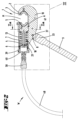
はじめに図1から11に関する図示及び記載内容は、油圧作動ツールWのデバイスヘッド1の第1の実施形態である。 First, the illustrations and description in Figures 1 to 11 show a first embodiment of a device head 1 of a hydraulically operated tool W.
デバイスヘッド1は、好ましくは一体的に一部品として形成され、第1ツール3を収容するためのカウンタホルダ2と、さらに一体的に一部品としてさらにシリンダ形構造体4とを有し、そこでセカンドツール5に対して作用する油圧ピストン6が、直接または非直接に誘導される方法で、直線的に変位可能である。
The device head 1 is preferably formed as one piece and has a
シリンダ形構造体4は、油圧シリンダ7を直接形成し、その中で油圧ピストン6が誘導される。
The
さらにデバイスヘッド1と一体的に一部品である、保持ロッド9の角度固定であるが変更可能な配置とするための歯形凹部8が前記デバイスヘッドに設置される。
Furthermore, a
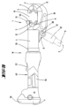
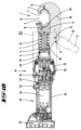
一体的に一部品として形成されるデバイスヘッド1は、全体として、図4で示す側面視または図3に示す長手方向断面図においてそれぞれ、おおよそC形状に設計され、そこで、油圧ピストンの軸xは、それ自体を直線として提示する。C形脚部は、上述のカウンタホルダ2を形作り、対向するC形脚部は基本的にシリンダ形構造体4を形成する。
これらのC形脚部は、基本的に油圧ピストンの軸xに沿って一直線に延びる接続脚部10(C-ウェブ)を介して相互に接続される。
The device head 1, which is formed in one integral piece, is designed as a whole approximately C-shaped in the side view shown in Figure 4 or in the longitudinal section shown in Figure 3, respectively, in which the axis x of the hydraulic piston presents itself as a straight line. The C-leg forms the above-mentioned
These C-legs are interconnected via a connecting leg 10 (C-web) which extends essentially in a straight line along the axis x of the hydraulic piston.
図示された例示的実施形態において、壁内側に直接接する油圧ピストン6のための摺動面を提供するシリンダ形構造体4は、軸xの直線に対して横方向の断面に関して外側の壁上で、円形円筒形状で基本的に形成される。この断面においてシリンダ形構造体4のシリンダ壁に接続される接続脚部10の部分は、これも好ましくは、軸xに関して基本的に半径方向に延在することができる。その場合、軸xと垂直な方向において、接続脚部10の対応する壁の厚さの寸法は、シリンダ形構造体4の外径の寸法に対応するよりも小さくなる。対応する接続脚部10の厚さを、シリンダ形構造体4の外径の約0.3から0.7倍に、さらには約0.5倍に一致させることができる。
In the illustrated exemplary embodiment, the
カウンタホルダ2は、第1ツール担持体11を形成する。第1ツール3は、その中に交換可能に、ロック可能な方法で、配置することができる。
The
第2ツール担持体12は、シリンダ形構造体4内に延在するピストンシャフト13と同一部品としてかつ同一素材で形成されることが好ましく、第1ツール担持体11またはその中に収容される第1ツール3に向かって移動可能である。当該ツール担持体12は、第2ツール5のための受容部Aを形成し、それが交換可能な方法でそこに保持されることが好ましい。その場合、ピストンシャフト13の軸の長さを、油圧ピストン6の最大変位経路のおよそ1.3~2.5倍に一致させることができる。
The
軸xを横切る図2aに示した断面図について、第2ツール担持体12は、基本的に引き延ばされた長方形の態様で形成され得る。図示された例示的実施形態においては、図2aに示すようにその使用状態において垂直に延びる長手方向の外縁は、引き延ばされた直線の態様で形成され、一方でそれに対し横方向となる短手方向の外縁の各々は、曲線に沿って誘導される。これらの曲線は、軸xに関して共通の半径を有する。半径は、シリンダ形構造体4における周囲のジャケット壁の直径に適応する。
周方向において第2ツール担持体12を固定するために、それによって軸x周りの回転を防ぐように、当該壁の外側の曲面の領域において第2ツール担持体12は、図示されるように、軸方向に延びかつジャケット壁に向けて開口した保持溝部14を有することができ、一般的な運用状態において、図示されるように、止めねじ15が保持溝部14と係合でき、止めねじ15が、図3で示される初期位置において、シリンダ形構造体4内に収容及び誘導される。そのシリンダ形構造体4は、第1ツール担持体11に向いた第2ツール担持体12の前面59におおよそ向かって延在する。
止めねじ15をそれぞれ緩めるかまたは取り外した後に、下記にてより詳細に記述するように、好ましくは、さらにクランピングスクリュー21、カバーパット20、そして任意にばね18を取り外した後に、第2ツール担持体12が、当該ツール担持体12と一部品として形成されるピストンシャフト13とともに、例えば図3に示す初期位置における第1ツール担持体11と第2ツール担持体11との間に生じる自由デバイス顎部Mを通り外に誘導することができ、または対応した組立が、この経路を通り各々行われ得る。軸xを中心として好ましくは約90度の当該ツール担持体12の回転は、選択的にこの目的のために必要とされる。
With respect to the cross-section shown in Fig. 2a across the axis x, the
In order to fix the
After loosening or removing, respectively, the
第2ツール担持体を収容するシリンダ形構造体4の一部は、図示されるように、シリンダ形構造体4の一部に比して拡大された直径を有することができ、そこで油圧ピストン6は誘導される。第2ツール担持体12を取り囲むシリンダ形構造体4の一部の内径は、油圧ピストン6を取り囲む一部の内径の約1.05~1.2倍に相当することができる。
The part of the
ステップは、さらに止め具16を形成することができ、止め具16はさらに半径方向内側に突出しかつ基本的に全体としてリング形状となる。それ故にステップは、第2ツール担持体12を囲むシリンダ形構造体4の一部から、油圧ピストン6を取り囲む一部への移行において、内側の壁に生じる。初期位置において、第2ツール担持体12は当該止め具16と反対に移動できる。
The step can further form a
基本的に軸xと同軸上で第2ツール担持体と連結するピストンシャフト13は、図示するように、基本的に軸長全体にわたり 中空の円筒23として形成され得る。その場合、その外径は、従ってシリンダ形構造体4の対応する一部の内径よりも小さくなり、よって環状空間17がピストンシャフト13を取り囲むように生じる。ピストンシャフト13の外径は、それ故に油圧ピストン6を取り囲むシリンダ形構造体4の一部の内径の約0.5~0.8倍に相当し得る。
The
例えば円柱の圧縮コイルばねの形状の、ばね18は、ピストンシャフト13を取り囲む環状空間17に設置される。このばね18は、円形のリング形状をしたスラストワッシャ19を介してデバイスヘッド1の止め具16に接する第2ツール担持体12に面したばね18の一端でそれ自体を支持し、一方で軸方向で反対に位置する他端が、ピストンシャフト13のカバー部20の対向する底面に対して作用する。
A
カバー部20は、それ故にピストンシャフト13の前面の自由端上に配置され、従って好ましくはピストンシャフト13のジャケット壁を越えて円周状に、放射状に、均一に突出する。ばね18は、このように形成された放射状のステップに対して作用することが好ましい。
The
カバー部20は、クランピングスクリュー21によって固定されることができる。クランピングスクリュー21は、軸xに沿って一直線となり、軸xに対して同心円状に整列した開口22の領域においてカバー部を通過する。クランピングスクリュー21は、さらにピストンシャフト13の中空の円筒23をその全長にわたり通過し、かつ一端に対応して位置する第2ツール担持体12のねじ穴24と螺合する。
The
上述の配置の結果として、第2ツール担持体12の取り付けは、例えば図3で示される初期位置の方向において、ばね18を通して行う。そこではツール担持体11と12すなわち、それらそれぞれに収容されるツール3と5が、軸方向において相互に最大距離を呈する。
As a result of the above-mentioned arrangement, the
油圧ピストン6は、カバー部20を具備して設置されるピストンシャフト13の一端に対して作用するよう配置される。この目的のために、油圧ピストン6全体は、図示するように、軸xに関して同心円状に延在するポット形状のデザインを有し、ばね18の一部分を半径方向外側において取り囲むことができる、ピストン壁25を備える。
The
ピストン底部26は、カバー部20の対向する前面に対してそのポットの内側の面により作用し、その場合、ピストン底部の内面は、例えばクランピングスクリュー21のねじ頭28を収容するための、中央の凹部27をさらに有することができる。
The piston bottom 26 acts by its pot inner surface against the facing front surface of the
加えて、これに関して、階段状の凹部を形成することができ、従ってとりわけカバー部20を、好ましくはカバー部20の軸方向の厚み全体及びねじ頭28を収容するために形成する(例えば図11を参照されたい)。
In addition, in this regard, a stepped recess can be formed, thus forming the
従ってピストン底部の内面は、ばね18のための支持面として役立つこともできる。よって初期位置の方向における復元力は、油圧ピストン6に対して、ばね18により直接に、またはカバー部20により間接的にのみ、作用する。
The inner surface of the piston bottom can therefore also serve as a support surface for the
径方向外側に開口した円周方向の環状の溝内にて、ピストン底部26の領域に拘束されたシール29は、油圧シリンダ7の内壁30に対して油圧ピストン6を封止するために、シリンダ形構造体4によって形成される。
A
ロッド9の保持を確保するための歯形凹部8が、これも好ましくは、図3に示す長手方向断面図に関し、接続脚部10の領域におけるシリンダ形構造体4から側面方向に離れて形成することもでき、これにより好ましくはシリンダ形構造体4と半径方向において重なる。すなわちこれは、歯形凹部8を、軸xの向きに対して横方向でかつシリンダ形構造体4の方向に投影した場合、歯形凹部8が実質的にそのシリンダ形構造体内に受容されることを意味する。
The
歯形凹部8は、図示するように、接続脚部10の一方の側のみで形成され得る。先ずこの目的のため、接続脚部10を完全に貫通する貫通孔31が設けられ、その周方向において相互に等間隔に離れて位置しかつ好ましくは同一に形成される凹部32が、歯形凹部8の形成のために円周方向に同心円状に、接続脚部10に設けることができる。従って、図7に図示するような12個の凹部32は、貫通孔31の周りに均一に分散した態様で設けることができる。
The tooth-shaped
保持端部33上に歯形凹部8によって固定可能である保持ロッド9は、カウンタ歯形凹部34を有し、図示された例示的実施形態によると、それが歯形凹部8の複数の凹部32に適合した複数の凸部35によって形成できる。
これらの凸部35は、それらの断面のデザイン及び奥行きに関して一致するように設計することもできる。これによりこれらの凸部35は、凹部32の配置に従い、周方向において相互に均等に設置できる。
The retaining
These
凸部35は、断面において凹部32に適合するので、デバイスヘッド1との保持ロッド9の完全な接続が、凹部32と凸部35との係合の結果としてハースセレーションの方法において実現することができる。
The
例示的方法において設置される12個の凹部32により、保持ロッド9の角度方向の緊締は、例示的実施形態に基づき30度ステップで行うことができる。異なった角度αは、基本的にデバイスヘッド1の長手方向の軸に対応する油圧ピストンの軸xと、保持ロッド9の長手方向の軸yとの間で示される。
Due to the twelve
ねじ孔36は、保持ロッド9の保持端33上の凸部35の配置の中央を通って保持端部33に設けられる。保持ロッド9の定位置において、このねじ孔36はデバイスヘッド1の貫通孔31と重なり合う。
The
保持ロッド9の見出された調整位置を固定し、それに対応して、歯形凹部8とカウンタ歯形凹部34の完全な接続位置を確保するために、固定ねじ37が設置される。これは、歯形凹部の反対に位置する側から入り、貫通孔31を通り、保持ロッド9のねじ孔36に係合する。デバイスヘッド1の歯形の凹部8と、保持ロッド9との、とりわけそれのカウンタ歯形凹部34との締め付けは、ねじ孔36と係合する一端とは反対側の他端に接続されたハンドリングノブ38によって実現することができる。
To fix the found adjustment position of the holding
保持ロッド9は、固定ねじ37により提供されかつ軸x及びyに対し垂直に延在する幾何学的旋回軸z周りに旋回することができる。
The retaining
このように調節されかつデバイスヘッドに固定された保持ロッド9を使用することで、デバイスヘッド1を、遠隔の動作位置に向けて誘導することもでき、かつ/またはデバイスヘッド1は、保持ロッド9により支持等することもできる。
By using the holding
第2ツール担持体2とは反対に向く方向において、シリンダ形構造体4は、さらに油圧ピストン6を越えて、図示からさらにわかるように軸xの延長方向において、とりわけピストン底部26を越えて延在することができる。初期位置において、油圧ピストン6はこうしてシリンダ形構造体4に完全に挿入される。
In the direction facing away from the
初期位置においてピストン底部26を越えて突出するシリンダ形構造体4の部分は、アダプタ部40のための連結レセプタクル39を形成することができる。それにより自由内径は、好ましくは、より大きく、例えば油圧シリンダ7を収容するシリンダ形構造体4の部分の領域における自由内径bと比較して、連結レセプタクル39の領域においてより大きく、例えば1.05~1.2倍大きくなるように選択することができる。
The part of the
さらに、内側のねじは、周方向のアダプタ部の壁41の領域で、アダプタ部40の外側のねじ山と係合させるため、連結レセプタクル39の内側の壁に形成できる。アダプタ部壁41はさらに好ましくは、壁外側に半径方向外側に開口する溝内側に位置するシール42を有することができ、シリンダ形構造体4または連結レセプタクル39の内壁30に対してそれぞれ作用する。
Furthermore, an internal thread can be formed on the inner wall of the
幾何学的軸xが中心を通過する中心において、軸xを横切るように配列されたアダプタ部底部43は、油圧媒体のための流入口44を維持する。外側すなわち油圧ピストン6とは反対側に向き、この流入口44は切り株状のアダプタ部連結部45によって取り囲まれる。
The
油圧ピストン6とは反対側に向くアダプタ部底部43の表面は、基本的にシリンダ形構造体4の割り当てられた前面8と整列させることができる。
The surface of the adapter part bottom 43 facing away from the
使用位置において、連結レセプタクル39にねじで止めるに当たり、アダプタ部40は、さらに連結レセプタクル39の壁を貫通するねじピン46を用いて固定することができる。
When screwed into the connecting
図1から図8において図示された第1の適用によれば、デバイスヘッド1は、独立した油圧ユニット47によって操作することができる。これによりデバイスヘッド1の自由な可動性のために、油圧ホース48は油圧ユニット47とデバイスヘッド1の間に配置される。図示の通り、アダプタ部40を用いて密閉するために、油圧ホース48は一端が油圧ユニット47に他端がデバイスヘッド1に、ホースコネクション58を用いて接続されている。
According to a first application illustrated in Figs. 1 to 8, the device head 1 can be operated by an independent
対応する油圧は、油圧ユニット47を用いて発生する。
The corresponding hydraulic pressure is generated using
油圧ピストン6と第2ツール5を担持するツール担持体12の、図3にて概略的に鎖線により示したその動作終点の方向における変位のために、作動油はアダプタ部40とピストン底部26との間に生じる空間に注入され、それによって生じる油圧ピストンの油圧の増加の結果として、油圧ピストンはばね18の復元力に抗して方向cへと変位する。
Due to the displacement of the
動作終点に到達すると、さらに選択的に動作終点への到着より前にも、圧力減少が自動的にまたは使用者による介入の結果としても得られることによって、初期位置へ戻る動作方向dへと、油圧ピストン6とそれに伴う第2ツール担持体12の自動的な復帰が実現される。
When the end point of the movement is reached, and optionally even before the end point of the movement is reached, a pressure reduction is obtained automatically or as a result of user intervention, thereby realizing an automatic return of the
代わりに、図9から図11にさらに示すように、デバイスヘッド1を本体キャスティングツール部49に接続することができる。アダプタ部40はこの目的にも供することができ、選択的に、油圧ホース48を接続するために使用されたものと同一のアダプタ部40であってもよく、代わりに本体キャスティングツール部49のために別途設置されたものでもよい。
Alternatively, as further shown in Figures 9 to 11, the device head 1 can be connected to the main body
本体キャスティングツール部49全体は、基本的に長尺のロッド形状のように形成されることができ、一般的にデバイスの片手操作をサポートする。保持ロッド9の可能な配置によって、デバイスヘッド1の領域において更なるサポートが与えられ得る。ツールWは本体キャスティングツール部49とデバイスヘッド1を備え、しかしながら保持ロッド9なしに単独で用いることもできる。これが保持ロッド9を第2の実施形態の図において鎖線で選択的にのみ示した理由である。工具なしで取り外せる固定ねじ37上の保持ロッド9の配置は、そのような選択的な配置を提供する。
The entire main body
ロッド形状の本体キャスティングツール部49は、上記で参照した特許文献2により公知である。とりわけ本体キャスティングツール部49の機能に関して、当該参照発明の特徴を本発明のクレームに含める目的のためにも、その全体が本発明の開示に含まれる。
The rod-shaped body
本体キャスティングツール部49の設計に関しても、上記特許文献2に記述された主題との関連は、図10における図示に関して、例えばリターンバルブ50、タンク51、そしてポンププランジャ52についてみることができる。全体として、これに関連して、油圧媒体ポンプ53と油圧媒体ポンプ53のための電気モータ54が、互いに前後する配置で設置される点でもみることができる。とりわけ電気モータ54による、さらには本体キャスティングツール部49における図示のない制御ユニットやさらなる電気的構成要素による電力供給は、蓄電池55の配置によって設置される。
With regard to the design of the main
本体キャスティングツール部49は、手によってツール部ハウジングを従来通り把持するためのグリップ領域56をさらに有する。グリップ領域56に割り当てられた作動ボタン57が、人間工学に適う方法で、設けられる。
The main
この実施形態の場合において、油圧ピストン6は圧力増加の結果として動作終点の方向に、ばね18の力に抗して変位させられる。
In this embodiment, the
図12から図16は、デバイスヘッド1の第2の実施形態を示す。これは上述の実施形態と比較して、とりわけデバイスヘッド1におけるシリンダ形構造体4と受容部Aまたは第2ツール担持体12の誘導に関し、それぞれ異なる。一般的な動作の形態と操作の形態、及び、受容部Aに対して油圧により作用するための一般的な構成は、基本的に上述の第1の実施形態に対応する。受容部Aまたは第2ツール担持体12は、好ましくはここに一部品として、さらに好ましくはピストンシャフト13と同一素材によって構成される。
Figures 12 to 16 show a second embodiment of the device head 1, which differs from the above-mentioned embodiments in particular with regard to the
この実施形態においては、上述の例示的実施形態とは対照的に、シリンダ形構造体4が、アダプタ部底部43を起点として、ピストンシャフト13から受容部Aへと階段状の移行において、受容部Aの前面59とは反対側に向いた背面60付近までしか延在しない。この実施形態では、受容部Aまたは第2ツール担持体12(選択的に第2ツール5を備える)は、接続脚部10の領域における底面の支持と誘導の領域を除き、相互に面しているシリンダ形構造体4とカウンタホルダ2の前面の間で露出している。
In this embodiment, in contrast to the exemplary embodiment described above, the
特に図14と図15で部分的に図示されるように、受容部Aまたは第2ツール担持体12は、例えばデバイスヘッド1の接続脚部10に面した底側に、図14の断面図において基本的にT形状のガイド凸部61を有することができる。図示するような従来の動作位置では、ガイド凸部61を、接続脚部10のガイド溝部62において誘導することができ、動作方向dに方向づけられる。従ってガイド凸部61のT形ヘッド67をガイド溝部62の溝底部に面するように、配置することができる。さらにガイド凸部のT形ヘッド67を、図14の断面図において対照的に括れているT形ウェブ68によって、第2ツール担持体12と連結することができる。
14 and 15, the receiving part A or the
ガイド凸部61とガイド溝部62の連携の結果として、軸xを中心とする受容部Aまたは第2ツール担持体12の回転に対する阻止が最初から与えられ、さらに受容部Aの線形の誘導も、動作方向dにおけるその変位へ応答するように与えられる。
As a result of the cooperation of the
動作方向dにみることができる長さlにわたり、デバイスヘッド1のガイド溝部62には部分的に下方切り欠き部63をさらに形成することができ、それは動作方向dに対して横方向に動作する。この下方切り欠き部63は、例えば図5の断面図において相互に対向して位置づけられるように配置され、相互に向き合ったリブ64により与えられ、それらは溝底部69から離れて形成され、かつT形ヘッド67と受容部Aとの間のガイド凸部61の括れ領域に係合するのに適している。
Over the length l visible in the operating direction d, the
図示された実施形態において、下方切り欠き部63は、例えば動作方向dにおけるガイド溝部62の長さlのおよそ半分にわたり、長さl全体のおよそ2/3または3/4まで、延在できる。さらに好ましくは、この下方切り欠き部の部分が特に受容部Aの従来の変位経路にわたって、従って変位経路の後ろの半分から後ろの3/4までにわたって延在し、それにより、特に力が加わったときの受容部Aの臨界的変位状況において、動作方向dに対し横方向への受容部Aの変位に抗する、適切な誘導と保護が提供される。
In the illustrated embodiment, the
従ってこの下方切り欠き部は、さらにとりわけ動作終点において与えられる。 This lower cutout is therefore provided, more particularly, at the end of the movement.
任意に基本位置、特に油圧ピストン6による作用を受けない基本位置を形成する図13に示す初期位置において、好ましくはガイド溝部62にリブ64が設けられておらず、それにより受容部Aと連携する下方切り欠き部はこの領域(特に図14で部分的に図示される)には設けられない。このことは、ピストンシャフト13と一部品を形成する受容部の好適な組立及び分解が、例えばプレスや切断のプロセスの際に受容部Aの回転や傾きに対する防止を伴って行われるという有利性を提供する。
In the initial position shown in FIG. 13, which optionally forms a basic position, in particular a basic position not acted upon by the
図16は、ピストンシャフト13または第2ツール担持体12と一部品に形成される受容部Aの、そのような組立または分解の位置をそれぞれ示している。分解のために、シール42を有するアダプタ部底部43とシール29を有するピストン底部26を、油圧シリンダ7から取り除くこともできる。その後にクランピングスクリュー21はそれを緩めるためにむき出しになる。ばね18と同様にカバー部20も、取り外すことができる。その後にピストンシャフト13は、油圧シリンダ7に、独立してかつ自由に配置される。
Figure 16 shows such an assembly or disassembly position of the receiver A, which is formed in one piece with the
この後に、受容部Aまたは第2ツール担持体12は動作方向dに対して横方向(矢印e参照)にシフトすることができ、よって、ガイド凸部61は、ガイド溝部62から離れることができる。矢印の方向eにおける、この持ち上がるまたは傾く動きは、ピストンシャフト13と共に受容部Aを、自由デバイス顎部mを通して取り外すための引き抜き方向f(基本的にピストンシャフト13の軸方向)と、直接重ね合わすことができる。組立は好ましくはこの逆の順序で行われる。
After this, the receiver A or the
さらにとりわけ図12に示すように、例えば油圧ホース48が接続されていないときなど、デバイスヘッド1が不使用の場合におけるホースコネクション58の自由端の領域において、プラグ65により、開口を塞ぐことができる。このプラグ65をさらにバンド66を用いてホースコネクション58に係留することができる。
More particularly, as shown in FIG. 12, in the region of the free end of the
第2ツール5が初期位置と動作終点との間を油圧ピストン6によって動作することができ、油圧ピストン6が、第2ツール5のための受容部に一部品として接続されているピストンシャフト13に対して作用することができること、かつピストンシャフト13が初期位置においてシリンダ形構造体4の中に完全に収容され得ることを特徴とするデバイスヘッド。
A device head characterized in that the
デバイスヘッド1が、角度固定であるが変更可能である保持ロッド9の配置のために一体的に一部品として形成された歯形凹部8をさらに有することを特徴とするデバイスヘッド。
A device head characterized in that the device head 1 further has a tooth-shaped
デバイスヘッド1の長手方向断面において、歯形凹部8が側面側に離れるように、しかしシリンダ形構造体4に重なるように、形成されることを特徴とするデバイスヘッド。
A device head characterized in that, in a longitudinal cross section of the device head 1, the tooth-shaped
歯形凹部8が中央の貫通孔31関して同心円状に円周状に形成されることを特徴とするデバイスヘッド。
A device head characterized in that the tooth-shaped
第2ツール5が、初期位置と動作終点との間において油圧ピストン6によって移動可能であること、ピストンシャフト13がピストンシャフト13と比較して油圧ピストン6の動作方向dに対して横方向に引き延ばされ第2ツール5に割り当てられる受容部Aを有すること、かつ動作終点において当該受容部Aがデバイスヘッド1に形成される下方切り欠き部63における動作方向dに対して横方向に保持されることを特徴とするデバイスヘッド。
A device head characterized in that the
第2ツール5とピストンシャフトが一部品として形成されるための受容部Aを特徴とするデバイスヘッド。
A device head characterized by a receiving portion A for forming the
初期位置において、受容部Aが組立または分解のために動作方向dに対して横方向に変位可能なことを特徴とするデバイスヘッド。 A device head characterized in that, in an initial position, the receiving portion A is displaceable laterally with respect to the operating direction d for assembly or disassembly.
デバイスヘッドが、油圧を発生させる油圧ユニット47と比較してデバイスヘッド1の自由な可動性のための油圧ホース48と接続され、油圧ホース48の他端が油圧ユニット47と接続されていることを特徴とするデバイスヘッド。
A device head characterized in that the device head is connected to a
デバイスヘッド1が本体キャスティングツール部49と固く連結されており、その中に油圧ユニットが配置されていることを特徴とするデバイスヘッド。
A device head characterized in that the device head 1 is firmly connected to the main body
第2ツール5が初期位置と動作終点との間を油圧ピストン6によって移動可能であり、かつ油圧ピストン6が初期位置においてシリンダ形構造体4に完全に収容されることを特徴とするデバイスヘッド。
A device head characterized in that the
シリンダ型構造体4が、油圧ピストン6の初期位置を基準とした油圧ピストン6を取り囲む領域の外側であって、油圧ピストン6の動作終点から初期位置への動作方向dの延長上に、本体キャスティングツール部49または油圧ホース48のための連結レセプタクル39を有することを特徴とするデバイスヘッド。
A device head characterized in that the
連結レセプタクル39が自由内径aを有し、それが、シリンダ形構造体4が初期位置において油圧ピストン6を取り囲む領域におけるシリンダ形構造体4の直径bよりも大きいことを特徴とするデバイスヘッド。
A device head characterized in that the connecting
油圧ピストン6が、ピストンシャフト13と、第2ツール5の反対側に向いたその一端に配置されたカバー部20と、を有することを特徴とするデバイスヘッド。
A device head characterized in that the
デバイスヘッドの長さの一部にわたってピストンシャフト13が中空の円筒23として形成されることを特徴とするデバイスヘッド。
A device head characterized in that the
クランピングスクリュー21が、中空の円筒23を貫通することでカバー部20を保持することを特徴とするデバイスヘッド。
A device head characterized in that a clamping
アダプタ部40が連結レセプタクル39に配置され、かつピストン底部26が初期位置においてアダプタ部40のピストン側前面と対向して配置されることを特徴とするデバイスヘッド。
A device head characterized in that the
開示された全ての特徴は、(それ自体のために、また互いに組み合わされて)本発明に不可欠である。ここでの出願の開示は、関連する/追加された優先権書類(先の出願の写し)の開示内容をその内容全体に含み、それはこれらの書類の特徴を本願の請求項に組み込む目的でもある。従属請求項は、特にこれらの請求項に基づいて分割出願を行うために、引用される請求項の特徴がなくても、先行技術の独立した発明性のあるさらなる発展を特徴とする。各請求項で特定された発明は、前述の説明で特定された、特に参照符号が付与された、及び/又は符号の説明で特定された、1つ以上の機能を追加で有することができる。本発明はまた、特に、それらがそれぞれの使用目的に明らかに不要であるか、又は技術的に同じ効果を有する他の手段で置き換えることができる限り、前述の説明で述べた特徴の個々のものが実装されない実施形態に関する。 All disclosed features are essential to the invention (both for themselves and in combination with one another). The disclosure of the present application includes in its entirety the disclosure content of the relevant/added priority documents (copies of the earlier application), also with a view to incorporating the features of these documents in the claims of the present application. The dependent claims are characterized by an independent, inventive further development of the prior art, even without the features of the claims cited, in particular in order to file a divisional application on the basis of these claims. The invention specified in each claim may additionally have one or more features specified in the preceding description, in particular those given reference signs and/or specified in the explanation of the signs. The present invention also relates in particular to embodiments in which individual ones of the features mentioned in the preceding description are not implemented, insofar as they are obviously unnecessary for the respective purpose of use or can be replaced by other means having the same technical effect.
1 デバイスヘッド
2 カウンタホルダ
3 第1ツール
4 シリンダ形構造体
5 第2ツール
6 油圧ピストン
7 油圧シリンダ
8 歯形凹部
9 保持ロッド
10 接続脚部
11 第1ツール担持部
12 第2ツール担持部
13 ピストンシャフト
14 保持溝部
15 止めねじ
16 止め具
17 環状空間
18 ばね
19 スラストワッシャ
20 カバー部
21 クランピングスクリュー
22 開口
23 中空の円筒
24 ねじ穴
25 ピストン壁
26 ピストン底部
27 凹部
28 ねじ頭
29 シール
30 内壁
31 貫通孔
32 凹部
33 保持端部
34 カウンタ歯形凹部
35 凸部
36 ねじ孔
37 固定ねじ
38 ハンドリングノブ
39 連結レセプタクル
40 アダプタ部
41 アダプタ部壁
42 シール
43 アダプタ部底部
44 流入口
45 アダプタ部連結部
46 ねじピン
47 油圧ユニット
48 油圧ホース
49 本体キャスティングツール部
50 リターンバルブ
51 タンク
52 ポンププランジャ
53 油圧媒体ポンプ
54 電気モータ
55 蓄電池
56 グリップ領域
57 作動ボタン
58 ホースコネクション
59 前面
60 後面
61 ガイド凸部
62 ガイド溝部
63 下方切り欠き部
64 リブ
65 プラグ
66 バンド
67 T形ヘッド
68 T形ウェブ
69 溝底部
b 内径
c 方向
d 動作方向
l 長さ
e 矢印
f 引き抜き方向
x 油圧ピストンの軸
y 保持ロッドの長手方向の軸
z 旋回軸
A 受容部
M デバイス顎部
W ツール
α 角度
1
Claims (17)
前記第2ツール担持体(12)が油圧ピストンの軸(x)に対して横方向の断面に関して引き延ばされた長方形の態様で形成され、使用状態において垂直に延びる長手方向の外縁が引き延ばされた直線の態様で形成され、一方でそれに対し横方向にみられる短手方向の外縁の各々が曲線に沿って誘導され、かつこの曲線が前記軸(x)に関して共通の半径を有し、そこで半径が前記シリンダ形構造体(4)における周囲のジャケット壁の直径に適合することを特徴とするデバイスヘッド。 The device comprises a counter holder (2) formed as one piece on the device head (1) and having a receptacle for a first tool (3), and a second tool (5) movable towards said counter holder (2) by means of a hydraulic piston (6), in association with which is provided a cylindrical structure (4) which is likewise one piece with said device head (1), and furthermore, said second tool (5) is movable by said hydraulic piston (6) between an initial position and an end point of movement, said hydraulic piston (6) being able to act on a piston shaft (13), said piston shaft (13) being adapted to move said second tool (5). a piston shaft (13) which is connected as one piece to a receiving part (A) for a piston shaft (13) extending in the cylindrical structure (4) and which can be completely accommodated in the initial position in the cylindrical structure (4), the counter holder (2) forming a first tool carrier (11) and a second tool carrier (12) made of the same material as the piston shaft (13) extending in the cylindrical structure (4) being movable towards the first tool carrier (11), the tool carrier (12) forming a receiving part (A) for a second tool (5) which is preferably held in an exchangeable manner,
1. A device head, characterized in that the second tool carrier (12) is formed in the manner of an elongated rectangle in a cross section transverse to the axis (x) of the hydraulic piston, the longitudinal outer edges extending perpendicularly in the use state are formed in the manner of elongated straight lines, while the short outer edges seen transverse thereto are each guided along a curve and this curve has a common radius in relation to the axis (x), where the radius matches the diameter of the surrounding jacket wall of the cylindrical structure (4).
Applications Claiming Priority (3)
| Application Number | Priority Date | Filing Date | Title |
|---|---|---|---|
| DE102019127497.4 | 2019-10-11 | ||
| DE102019127497.4A DE102019127497A1 (en) | 2019-10-11 | 2019-10-11 | Device head of a hydraulically operated tool |
| PCT/EP2020/078276 WO2021069587A1 (en) | 2019-10-11 | 2020-10-08 | Device head of a hydraulically actuatable tool |
Publications (2)
| Publication Number | Publication Date |
|---|---|
| JP2023504764A JP2023504764A (en) | 2023-02-07 |
| JP7620009B2 true JP7620009B2 (en) | 2025-01-22 |
Family
ID=72852631
Family Applications (1)
| Application Number | Title | Priority Date | Filing Date |
|---|---|---|---|
| JP2022520520A Active JP7620009B2 (en) | 2019-10-11 | 2020-10-08 | Hydraulic tool device head |
Country Status (7)
| Country | Link |
|---|---|
| US (2) | US12151356B2 (en) |
| EP (2) | EP4041471B1 (en) |
| JP (1) | JP7620009B2 (en) |
| KR (1) | KR20220080152A (en) |
| CN (2) | CN120901174A (en) |
| DE (1) | DE102019127497A1 (en) |
| WO (1) | WO2021069587A1 (en) |
Families Citing this family (9)
| Publication number | Priority date | Publication date | Assignee | Title |
|---|---|---|---|---|
| DE102020131036A1 (en) * | 2020-10-12 | 2022-04-14 | Gustav Klauke Gmbh | Hydraulically operated working device designed as a hand-held device |
| USD1042068S1 (en) * | 2021-05-19 | 2024-09-17 | Gustav Klauke Gmbh | Hydraulic press tool |
| USD1037815S1 (en) | 2021-05-28 | 2024-08-06 | Gustav Klauke Gmbh | Press head for a hydraulic press tool |
| EP4245466B1 (en) * | 2022-03-14 | 2025-01-29 | Dubuis et Cie | Portable hydraulic tool comprising a handle |
| US12263570B2 (en) * | 2022-06-06 | 2025-04-01 | Enerpac Tool Group Corp. | Hydraulic tools |
| WO2023237776A1 (en) | 2022-06-10 | 2023-12-14 | Gustav Klauke Gmbh | Hand tool |
| CN119173358A (en) | 2022-06-10 | 2024-12-20 | 古斯塔夫·克劳克有限责任公司 | Hand-held tool |
| CN120265862A (en) * | 2022-11-23 | 2025-07-04 | 豪倍公司 | Components used to adjust the force in reciprocating components |
| KR102699972B1 (en) * | 2024-06-07 | 2024-08-29 | (주)대진유압기계 | Portable copper pipe lock ring compression hydraulic tool |
Citations (5)
| Publication number | Priority date | Publication date | Assignee | Title |
|---|---|---|---|---|
| US7254982B2 (en) | 2002-04-10 | 2007-08-14 | Gustav Klauke Gmbh | Electrohydraulic pressing device and method for operating the same |
| JP2009505836A (en) | 2005-08-26 | 2009-02-12 | エフシーアイ | Hydraulic tool for automatic adjustment of die holder |
| WO2015087397A1 (en) | 2013-12-10 | 2015-06-18 | 株式会社泉精器製作所 | Hydraulic tool |
| JP2018133984A (en) | 2016-12-09 | 2018-08-23 | センブレ エス.ピー.エー. | Processing head for compression or cutting tools |
| DE102018102162A1 (en) | 2017-10-02 | 2019-04-04 | Gustav Klauke Gmbh | hand tool |
Family Cites Families (14)
| Publication number | Priority date | Publication date | Assignee | Title |
|---|---|---|---|---|
| US3017905A (en) * | 1957-03-05 | 1962-01-23 | Nat Telephone Supply Co | Hot line stick |
| US2968202A (en) * | 1958-04-11 | 1961-01-17 | Amp Inc | Hydraulic crimping tool for crimping t-tap connectors |
| US3326029A (en) * | 1964-08-05 | 1967-06-20 | Porter Inc H K | Hydraulic press |
| US5062290A (en) * | 1990-06-25 | 1991-11-05 | Burndy Corporation | Hydraulic crimping press for electrical connectors |
| US5337566A (en) * | 1993-03-18 | 1994-08-16 | Burndy Corporation | Powder actuated compression tool |
| DE19944229B4 (en) | 1999-09-15 | 2016-07-28 | Gustav Klauke Gmbh | Hydraulic hand press and replaceable head for this purpose |
| US7124619B1 (en) * | 2005-08-26 | 2006-10-24 | Fci Americas Technology, Inc. | Hydraulic tool working head |
| CN102909710B (en) * | 2011-08-06 | 2015-04-22 | 苏州宝时得电动工具有限公司 | Power tool |
| US20160344170A1 (en) | 2012-10-12 | 2016-11-24 | Carl Russel Tamm | Remote Control Tool Assembly For Use In Live Line Environments |
| US9393683B2 (en) * | 2014-05-02 | 2016-07-19 | M. W. Bevins Co. | Conductive boot for power tool protection |
| CN111451998A (en) * | 2014-07-07 | 2020-07-28 | 塞母布雷有限公司 | Fluid power compression or cutting tool and method of actuating a fluid power compression tool |
| US9774159B2 (en) * | 2015-01-16 | 2017-09-26 | Ridge Tool Company | Deflection compensating press tools |
| CN105500278B (en) * | 2016-01-05 | 2017-08-15 | 艾默生管道工具(上海)有限公司 | Hydraulic tool |
| CN208773362U (en) * | 2018-08-31 | 2019-04-23 | 上海沃恒机械设备有限公司 | Hydraulic tongs |
-
2019
- 2019-10-11 DE DE102019127497.4A patent/DE102019127497A1/en active Pending
-
2020
- 2020-10-08 CN CN202511012639.6A patent/CN120901174A/en active Pending
- 2020-10-08 JP JP2022520520A patent/JP7620009B2/en active Active
- 2020-10-08 EP EP20790233.9A patent/EP4041471B1/en active Active
- 2020-10-08 WO PCT/EP2020/078276 patent/WO2021069587A1/en not_active Ceased
- 2020-10-08 KR KR1020227015520A patent/KR20220080152A/en active Pending
- 2020-10-08 US US17/754,496 patent/US12151356B2/en active Active
- 2020-10-08 CN CN202080081161.1A patent/CN114728325B/en active Active
- 2020-10-08 EP EP24154342.0A patent/EP4349532A3/en active Pending
-
2024
- 2024-10-17 US US18/918,452 patent/US20250042010A1/en active Pending
Patent Citations (5)
| Publication number | Priority date | Publication date | Assignee | Title |
|---|---|---|---|---|
| US7254982B2 (en) | 2002-04-10 | 2007-08-14 | Gustav Klauke Gmbh | Electrohydraulic pressing device and method for operating the same |
| JP2009505836A (en) | 2005-08-26 | 2009-02-12 | エフシーアイ | Hydraulic tool for automatic adjustment of die holder |
| WO2015087397A1 (en) | 2013-12-10 | 2015-06-18 | 株式会社泉精器製作所 | Hydraulic tool |
| JP2018133984A (en) | 2016-12-09 | 2018-08-23 | センブレ エス.ピー.エー. | Processing head for compression or cutting tools |
| DE102018102162A1 (en) | 2017-10-02 | 2019-04-04 | Gustav Klauke Gmbh | hand tool |
Also Published As
| Publication number | Publication date |
|---|---|
| CN120901174A (en) | 2025-11-07 |
| EP4349532A3 (en) | 2024-09-04 |
| US12151356B2 (en) | 2024-11-26 |
| WO2021069587A1 (en) | 2021-04-15 |
| US20230405788A1 (en) | 2023-12-21 |
| JP2023504764A (en) | 2023-02-07 |
| EP4349532A2 (en) | 2024-04-10 |
| US20250042010A1 (en) | 2025-02-06 |
| KR20220080152A (en) | 2022-06-14 |
| EP4041471A1 (en) | 2022-08-17 |
| DE102019127497A1 (en) | 2021-04-15 |
| EP4041471B1 (en) | 2024-03-06 |
| CN114728325B (en) | 2025-07-22 |
| CN114728325A (en) | 2022-07-08 |
Similar Documents
| Publication | Publication Date | Title |
|---|---|---|
| JP7620009B2 (en) | Hydraulic tool device head | |
| US4154083A (en) | Expanding head for pipe end enlarging tools | |
| US6546633B1 (en) | Reciprocating saw holder | |
| EP2091682B1 (en) | An apparatus for facilitating an in use connection of an accessory and a drill | |
| CA2201844A1 (en) | Fastener-driving tool having adjustable controlling mechanism | |
| US4021914A (en) | Guide handle for power tools | |
| CN101486182A (en) | Power tool with spindle lock | |
| HUT71167A (en) | Pressing tool | |
| US7736217B2 (en) | Hand-held power tool with protection hood | |
| US6651939B2 (en) | Shower fitting holder | |
| MA29758B1 (en) | ADJUSTABLE BALANCED CENTERING TOOL FOR USE IN VARIABLE DIAMETER PIPES | |
| US20090071670A1 (en) | Hand-held power tool | |
| WO1986003562A1 (en) | Locking device | |
| JP3443648B2 (en) | Crimping equipment | |
| FI77097B (en) | VENTIL ISYNNERHET FOER EN HANDSLIPMASKIN. | |
| JP3065151U (en) | Metal tube hydraulic forming machine with multiple functions | |
| US6715335B2 (en) | Portable crimping device for crimping fitting sockets | |
| CN115397615B (en) | Device and method for connecting a cooling nozzle to a cooling lubricant supply | |
| EP4257760A1 (en) | Pipe cleaning machine | |
| WO1998008652A1 (en) | Edge clamp apparatus | |
| JPH0248330B2 (en) | ||
| US20020020257A1 (en) | Tube machining and facing apparatus | |
| US12151340B1 (en) | Portable utility vise device | |
| US20020134203A1 (en) | Hand-operated multifunction tool | |
| EP1042097B1 (en) | Chuck with axial positioning device |
Legal Events
| Date | Code | Title | Description |
|---|---|---|---|
| A529 | Written submission of copy of amendment under article 34 pct |
Free format text: JAPANESE INTERMEDIATE CODE: A529 Effective date: 20220401 |
|
| A521 | Request for written amendment filed |
Free format text: JAPANESE INTERMEDIATE CODE: A523 Effective date: 20221208 |
|
| A621 | Written request for application examination |
Free format text: JAPANESE INTERMEDIATE CODE: A621 Effective date: 20230921 |
|
| A977 | Report on retrieval |
Free format text: JAPANESE INTERMEDIATE CODE: A971007 Effective date: 20240912 |
|
| A131 | Notification of reasons for refusal |
Free format text: JAPANESE INTERMEDIATE CODE: A131 Effective date: 20240918 |
|
| A521 | Request for written amendment filed |
Free format text: JAPANESE INTERMEDIATE CODE: A523 Effective date: 20241108 |
|
| A521 | Request for written amendment filed |
Free format text: JAPANESE INTERMEDIATE CODE: A523 Effective date: 20241114 |
|
| TRDD | Decision of grant or rejection written | ||
| A01 | Written decision to grant a patent or to grant a registration (utility model) |
Free format text: JAPANESE INTERMEDIATE CODE: A01 Effective date: 20241219 |
|
| A61 | First payment of annual fees (during grant procedure) |
Free format text: JAPANESE INTERMEDIATE CODE: A61 Effective date: 20250109 |
|
| R150 | Certificate of patent or registration of utility model |
Ref document number: 7620009 Country of ref document: JP Free format text: JAPANESE INTERMEDIATE CODE: R150 |