JP7621605B2 - Automatic water soap dispenser - Google Patents
Automatic water soap dispenser Download PDFInfo
- Publication number
- JP7621605B2 JP7621605B2 JP2021041083A JP2021041083A JP7621605B2 JP 7621605 B2 JP7621605 B2 JP 7621605B2 JP 2021041083 A JP2021041083 A JP 2021041083A JP 2021041083 A JP2021041083 A JP 2021041083A JP 7621605 B2 JP7621605 B2 JP 7621605B2
- Authority
- JP
- Japan
- Prior art keywords
- main body
- section
- connection
- flow path
- liquid soap
- Prior art date
- Legal status (The legal status is an assumption and is not a legal conclusion. Google has not performed a legal analysis and makes no representation as to the accuracy of the status listed.)
- Active
Links
Images


Landscapes
- Domestic Plumbing Installations (AREA)
Description
本発明は、洗面台に支持部を介して固定される自動水石鹸供給装置に関し、詳細には、デザイン性と固定強度を低下させることなく胴回りの細いスタイリッシュな自動水石鹸供給装置を提供するものである。 The present invention relates to an automatic liquid soap dispenser that is fixed to a washbasin via a support part, and more specifically, to provide a stylish automatic liquid soap dispenser with a slim waist without compromising design and fixing strength.
洗面台においては、湯水を供給する水栓のほかに、使用者が一定の動作を行うと水石鹸が供給される水石鹸供給装置が併設されたものがある。このような水石鹸供給装置においては、使用者が吐出口付近に手を近づけるだけで、自動的に水石鹸が吐出される自動水石鹸供給装置が知られている(例えば、特許文献1参照。)。この自動水石鹸供給装置の本体部は下方を入り口とする収納空間が内部に形成される。また、本体部の下方から収納空間に機能部が設置され、機能部は少なくとも手を検知するセンサを有する。 Some washbasins are equipped with a water faucet that supplies hot and cold water, as well as a water soap dispenser that supplies liquid soap when the user performs a certain action. Among such water soap dispensers, an automatic water soap dispenser is known that automatically dispenses liquid soap when the user simply places their hand close to the outlet (see, for example, Patent Document 1). The main body of this automatic water soap dispenser has a storage space formed inside, with the entrance at the bottom. In addition, a functional unit is installed in the storage space from below the main body, and the functional unit has a sensor that detects at least the hand.
自動水石鹸供給装置では、手動式の水石鹸供給装置に比べて内部の収納空間に設置される機能部の多さに加え、取り付け性の確保や強度確保の観点から、どうしても本体部の胴回りが細くならず、デザイン性が悪くなるという課題があった。 Compared to manual liquid soap dispensers, automatic liquid soap dispensers require more functional parts to be installed in the internal storage space, and from the standpoint of ensuring ease of installation and strength, the girth of the main body cannot be made thin, resulting in poor design.
具体的に、自動水石鹸供給装置は、本体部の内部に収納空間が形成され、本体部の下方を収納空間の入り口として、収納空間に機能部が取り付けられる。本体部の内部には固定部が形成され、固定部は洗面台に固定される支持部と固定される。固定部と支持部は、ボルトである接続部によって接続される。従来、固定部は、機能部を取り付ける際に収納空間の入り口となる本体部の内部の下方に設けられていた。 Specifically, in the automatic liquid soap dispenser, a storage space is formed inside the main body, and the functional part is attached to the storage space with the lower part of the main body serving as the entrance to the storage space. A fixing part is formed inside the main body, and the fixing part is fixed to a support part that is fixed to the washbasin. The fixing part and the support part are connected by a connecting part that is a bolt. Conventionally, the fixing part was provided at the lower part inside the main body, which becomes the entrance to the storage space when the functional part is attached.
自動水石鹸供給装置は、水回り製品であり、水垢などの汚れが付着するため、頻繁に拭き掃除される。自動水石鹸供給装置の中でも、本体部は洗面台から上方に延びる形状のため、清掃等で本体部の上方に力が加わると、てこの原理によって本体部と支持部を固定する固定部と接続部に大きな力が加わる。よって、清掃のたびに大きな力が加わることから、固定部と接続部の固定強度が必要となる。よって、固定強度を低下させないために固定部と接続部を小さくすることに限界があった。 Automatic liquid soap dispensers are wet-area products that are prone to collecting limescale and other dirt, and are therefore wiped clean frequently. The main body of the automatic liquid soap dispenser extends upward from the sink, so when force is applied upward to the main body during cleaning, etc., a large force is applied to the fixing and connecting parts that secure the main body and support part due to the principle of leverage. As a result, the fixing and connecting parts require a certain level of fixing strength, as a large force is applied every time cleaning is performed. As a result, there is a limit to how small the fixing and connecting parts can be made without reducing the fixing strength.
自動水石鹸供給装置のデザイン性を向上するため本体部の胴回りを細くすると、本体部の内部も伴って細くなる。本体部の内部において、収納空間の入り口は細くできるが、固定部は固定強度を低下させないために小さくできない。この状況下において、機能部を収納空間に取り付ける際に、本体部の内部の下方に設けられた固定部が、機能部の取り付けを妨げることが分かった。解決手段の一つとして、固定部を下方に設けたまま、自動水石鹸供給装置の本体部の上方から機能部を取り付け、本体部の機能部が露出しないように蓋を設ける仕様も考えられる。しかし、蓋と本体部との接続により境界線ができ、デザイン性が低下する問題があった。このように、デザイン性を維持するために本体部の下方から機能部を取り付ける状況下において、固定強度を低下させることなく、本体部の胴回りを細くすることが困難であった。 When the girth of the main body is narrowed to improve the design of the automatic liquid soap dispenser, the inside of the main body is also narrowed. Inside the main body, the entrance to the storage space can be narrowed, but the fixing part cannot be made smaller in order to maintain the strength of the fixing. Under these circumstances, it was found that the fixing part provided at the bottom inside the main body prevents the functional part from being attached to the storage space. As one solution, it is possible to attach the functional part from above the main body of the automatic liquid soap dispenser while leaving the fixing part at the bottom, and to provide a lid so that the functional part of the main body is not exposed. However, there is a problem that a boundary line is created by the connection between the lid and the main body, which reduces the design. In this way, in a situation where the functional part is attached from below the main body to maintain the design, it is difficult to narrow the girth of the main body without reducing the strength of the fixing.
本件発明は、この様な課題に鑑みて、デザイン性と、ボルト等の接続部と固定部による固定強度を低下させることなく、自動水石鹸供給装置であっても本体部の胴回りを細くでき、スタイリッシュなデザインを提供できる自動水石鹸供給装置を提供せんとするものである。 In view of these problems, the present invention aims to provide an automatic liquid soap dispenser that can provide a stylish design by making the girth of the main body narrower without compromising design and the fixing strength of the connecting parts and fixing parts such as bolts.
本発明は、使用者の手を検知した際に水石鹸を吐出する自動水石鹸供給装置において、上方に向かって延び、下方を入り口とする収納空間が内部に形成された本体部と、前記本体部の下方から前記収納空間内に設置され、少なくとも手を検知するセンサを有する機能部と、洗面台に固定される支持部と、前記本体部の内部に形成された固定部と、前記固定部と前記支持部とに接続される接続部と、を備え、前記固定部は、前記機能部より上方に設けられていることを特徴とする。 The present invention is an automatic liquid soap dispenser that dispenses liquid soap when it detects a user's hands, and is characterized in that it comprises a main body portion that extends upward and has a storage space formed therein with an entrance at the bottom, a functional portion that is installed in the storage space from below the main body portion and has a sensor that detects at least the hands, a support portion that is fixed to the washbasin, a fixing portion formed inside the main body portion, and a connection portion that connects the fixing portion and the support portion, and the fixing portion is provided above the functional portion.
このように構成された本件発明によれば、本体部の内部に、固定強度を維持できる大きさの固定部を設けた場合であっても、本体部の内部に形成される収納空間の入り口において、機能部の取り付けが固定部によって妨げられることなく、且つ、機能部と固定部とが水平方向にオーバーラップすることがないことから本体部の胴回りを細くすることができる。よって、デザイン性と固定強度を低下させることなく、自動水石鹸供給装置であっても本体部の胴回りを細くでき、スタイリッシュな自動水石鹸供給装置を提供することができる。 According to the present invention configured in this way, even if a fixing part large enough to maintain the fixing strength is provided inside the main body, the attachment of the functional part is not hindered by the fixing part at the entrance to the storage space formed inside the main body, and the functional part and the fixing part do not overlap horizontally, so the girth of the main body can be made narrower. Therefore, even in the case of an automatic liquid soap dispenser, the girth of the main body can be made narrower without compromising the design and fixing strength, making it possible to provide a stylish automatic liquid soap dispenser.
また、前記本体部は、吐出口を有するスパウト部と、前記スパウト部に水石鹸を送るための内部流路と、を有し、前記内部流路は、前記スパウト部に接続され、略水平に延びる水平流路と、前記水平流路に接続され、下方に延びる下方流路と、を有し、前記固定部は、前記水平流路より下方に設けられていることを特徴とする。 The main body has a spout with a discharge port and an internal flow path for sending liquid soap to the spout, the internal flow path has a horizontal flow path connected to the spout and extending substantially horizontally, and a downward flow path connected to the horizontal flow path and extending downward, and the fixing part is provided below the horizontal flow path.
このように構成された本件発明によれば、本体部の内部に形成される固定部は水平流路の下方に設けられ、接続部は本体部の下方から固定部に接続されることから、固定部と接続部が水平流路に干渉することを避けることができ、本体部の内部において、デッドスペースを削減しつつ、固定部と水平流路の配置が可能となる。よって、本体部の胴回りを更に細くすることができる。 According to the present invention configured in this way, the fixing part formed inside the main body is provided below the horizontal flow path, and the connection part is connected to the fixing part from below the main body, so that the fixing part and the connection part do not interfere with the horizontal flow path, and it is possible to arrange the fixing part and the horizontal flow path while reducing dead space inside the main body. Therefore, the girth of the main body can be further reduced.
また、前記本体部の収納空間は、前記機能部が設けられている高さ位置において、前記本体部の高さ方向に延びる軸を中心に90度ごとに第1区画、第2区画、第3区画、第4区画に区画され、前記接続部は、前記機能部が設けられている高さ位置において、前記第1区画に設けられた第1接続部材と、前記第2区画に設けられた第2接続部材と、を有し、前記下方流路は、前記機能部が設けられている高さ位置において、前記第3区画または前記第4区画に位置していることを特徴とする。 The storage space of the main body is divided into a first section, a second section, a third section, and a fourth section at 90 degree intervals around an axis extending in the height direction of the main body at the height position where the functional section is provided, and the connection section has a first connection member provided in the first section and a second connection member provided in the second section at the height position where the functional section is provided, and the downward flow path is located in the third section or the fourth section at the height position where the functional section is provided.
このように構成された本件発明によれば、第1区画に設けられた第1接続部材と、第2区画に設けられた第2接続部材の2部材より、固定強度を高めることができる。また、本体部の高さ方向に延びる軸を中心に90度ごとに区画された区画に対して、第1接続部材と第2接続部材と下方流路とが区画ごとに配置されることから、限られた広さである本体部の内部において、デッドスペースを削減しつつ、接続部と下方流路の配置が可能になる。よって、固定強度を低下させることなく、本体部の胴回りをさらに細くすることができる。 According to the present invention configured in this way, the fixing strength can be increased by using two members, the first connecting member provided in the first compartment and the second connecting member provided in the second compartment. In addition, the first connecting member, the second connecting member, and the downward flow path are arranged in each compartment, which are divided every 90 degrees around an axis extending in the height direction of the main body, so that it is possible to arrange the connection part and the downward flow path while reducing dead space inside the main body, which has a limited area. Therefore, the girth of the main body can be made even thinner without reducing the fixing strength.
また、前記機能部は、前記センサを内部に保持する保持部材を有し、前記保持部材は、前記固定部まで前記接続部を誘導するためのガイド部が設けられていることを特徴とする。 The functional unit has a holding member that holds the sensor therein, and the holding member is provided with a guide portion for guiding the connection portion to the fixed portion.
本件発明において、本体部の胴回りを細くするために、固定部は機能部よりも上方に設けられた。これにより、固定部は本体部の下方に形成される収納空間の入り口から遠ざかった位置に設けられる。よって、接続部が固定部に固定される際に、固定作業を行う作業者から見えにくくなり、接続部の固定部に対する取り付け作業性が悪化するという特有の課題が生まれた。
本件発明は、この特有の課題である取り付け作業性の悪化を防止できたものである。具体的には、保持部材に固定部まで接続部を誘導するためのガイド部が設けられる。これにより、接続部を固定部に固定する際に、見え難い作業であってもガイド部に沿って接続部を挿入するだけで接続部は固定部に誘導される。また、保持部材とガイド部が共通の部材であるため、ガイド部が、保持部材と別部材として配置される場合と比べて、本体部の胴回りを細くすることができつつ、接続部の固定部に対する取り付け作業性の悪化を防止できる。
In the present invention, in order to reduce the girth of the main body, the fixing part is provided above the functional part. As a result, the fixing part is provided at a position away from the entrance of the storage space formed below the main body. Therefore, when the connecting part is fixed to the fixing part, it is difficult for the worker performing the fixing work to see, which creates a unique problem in that the workability of attaching the connecting part to the fixing part is deteriorated.
The present invention has been able to prevent this particular problem of deterioration in ease of installation. Specifically, a guide portion for guiding the connection portion to the fixed portion is provided on the holding member. As a result, when fixing the connection portion to the fixed portion, the connection portion is guided to the fixed portion simply by inserting the connection portion along the guide portion, even in a difficult-to-see operation. In addition, since the holding member and the guide portion are a common member, the girth of the main body can be made thinner compared to a case in which the guide portion is disposed as a separate member from the holding member, while preventing deterioration in ease of installation of the connection portion to the fixed portion.
また、前記接続部は、第1接続部材と、第2接続部材と、を有し、前記ガイド部は、水平方向において、前記第1接続部材および前記第2接続部材が前記センサを挟む位置となるように前記第1接続部材および前記第2接続部材を支持することを特徴とする。 The connection portion has a first connection member and a second connection member, and the guide portion supports the first connection member and the second connection member so that the first connection member and the second connection member are positioned to sandwich the sensor in the horizontal direction.
このように構成された本件発明によれば、ガイド部をセンサの位置決め手段として兼用でき、本体部の胴回りをさらに細くすることができる。また、接続部が第1接続部材と第2接続部材の2部材設けられることによって、センサが傾きにくく、固定強度を低下させることなく、適切な位置にセンサの照射範囲を設定しやすくなる。 According to the present invention configured in this way, the guide portion can also be used as a positioning means for the sensor, and the girth of the main body can be made even thinner. In addition, by providing the connection portion with two members, the first connection member and the second connection member, the sensor is less likely to tilt, and it is easier to set the sensor's irradiation range in an appropriate position without reducing the fixing strength.
本発明の態様によれば、デザイン性と、ボルト等の接続部と固定部による固定強度を低下させることなく、自動水石鹸供給装置であっても本体の胴回りを細くでき、スタイリッシュなデザインの自動水石鹸供給装置を提供できる。 According to this aspect of the present invention, it is possible to provide an automatic liquid soap dispenser with a stylish design by making the girth of the main body narrower without compromising the design and the fixing strength of the connection parts and fixing parts such as bolts.
以下、添付図面を参照しながら、本発明の実施の形態について説明する。説明の理解を容易にするために、各図面において同一の構成要素に対しては可能な限り同一の符号を付して、重複する説明は省略する。なお、以下に示す実施の形態によりこの発明が限定されるものではない。 The following describes an embodiment of the present invention with reference to the attached drawings. To facilitate understanding of the description, the same components in each drawing are given the same reference numerals as much as possible, and duplicate descriptions are omitted. Note that the present invention is not limited to the embodiment described below.
自動水石鹸供給装置4について図1乃至図6を参照しながら説明する。図1は、本発明の実施の形態に係る自動水石鹸供給装置4を設置した洗面台1を表す全体斜視図である。図2は、本発明の実施の形態に係る自動水石鹸供給装置4を表す斜視図である。図3は、本発明の実施の形態に係る自動水石鹸供給装置4を洗面台1から取り外した状態における斜視図である。図4は、本発明の実施の形態に係る自動水石鹸供給装置4の分解斜視図である。図5は、図2におけるA-A’線での断面図である。図6は図2におけるB-B‘線での模式的断面図である。
The automatic
図1に示すように、洗面台1は、湯水を供給する水栓2と、洗面ボウル3と使用者の手を検知した際に水石鹸を吐出する自動水石鹸供給装置4と、を備える。この自動水石鹸供給装置4は、使用者が自動水石鹸供給装置4の付近に手を近づけるだけで、自動的に水石鹸が吐出されるようになっている。
As shown in FIG. 1, the
ここで、本明細書においては、自動水石鹸供給装置4と向き合う使用者からみて手前側を「前方」とし、奥側を「後方」とし、上側を「上方」とし、下側を「下方」とし、右側を「右側方」とし、左側を「左側方」とする。
In this specification, the front side from the perspective of a user facing the automatic
図2乃至図6に示すように、自動水石鹸供給装置4は、上方に向かって延び、下方を入り口とする収納空間11が内部に形成された本体部10と、本体部10の収納空間11内に設置される機能部50と、洗面台1に固定される支持部40と、本体部10の内部に形成された固定部110と、固定部110と支持部40とに接続される接続部100と、を備える。また、自動水石鹸供給装置4は、洗面台1の間に座面を確保するワッシャーとして機能する台座90と、パッキン44と、支持部40を洗面台1に固定するための、クッションパッキン45と、スリップワッシャー46と、つば付きナット47と、を備える。
2 to 6, the automatic
本体部10は、中空の円柱形状であり、側面と上面を持ち、下方の底面を持たない形状である。本体部10の水平方向の断面は円であり、垂直方向の断面はコの字型である。
本体部10の胴回りは、本体部10の水平方向の断面でできる円の直径と定義する。従来は本体部の胴回りは外径が40mmよりも大きく、内径は38mmよりも大きかった。本実施形態において、本体部10の胴回りの外径は33mm~39mmで、内径は30mm~37mmである。
The
The girth of the
本体部10は、上方部13と、下方部14とを有し、下方部14に収納空間11の入り口となる入り口部12が形成される、また、本体部10は、水石鹸を吐出する吐出口21を有するスパウト部20と、センサ窓30と、水石鹸供給源(図示なし)から、スパウト部20に水石鹸を送るための内部流路80と、を有する。スパウト部20は、本体部10の上方部13から前方に突出する部材であり、スパウト部20の後端が本体部10の内部流路80に接続され、スパウト部20の前端に吐出口21が形成されている。図示されている本体部10とスパウト部20の形状は円柱形状であるが、その限りでなく、例えば多角柱でもよい。
The
センサ窓30は、本体部10の側面上に設けられ、使用者と使用者の手を検知するセンサ60の間に配置される。具体的に、センサ窓30は、収納空間11の内部に取り付けられるセンサ60が裏側となる本体部10の側面上に設けられる。
The sensor window 30 is provided on the side of the
本体部10の内部に設けられる内部流路80は、前後方向に向かって、略水平に延びる水平流路81と、水平流路81に接続され、水平流路81から下方に延びる下方流路82を有する。なお、略水平は、水平を0°として+5°から-5°の範囲である。水平流路81は、本体部10の内部に形成され、本体部10の側面上に取り付けられるスパウト部20と本体部10の内部の収納空間11に取り付けられる下方流路82を接続することで、水平流路81は水石鹸を下方流路82からスパウト部20へと供給する。
The internal flow path 80 provided inside the
下方流路80は、例えば可撓性のホースで構成され、収納空間11に取り付けられる。下方流路80は水石鹸を混合室部87に供給する水石鹸ホース83と、空気を混合室部87に供給する空気ホース84を有する。水石鹸は水石鹸供給源(図示せず)からポンプ(図示せず)によって水石鹸ホース83に供給され、空気はポンプ(図示せず)によって空気ホース84に供給される。
The downward flow path 80 is formed, for example, by a flexible hose, and is attached to the storage space 11. The downward flow path 80 has a
機能部50は、少なくともセンサ60を有し、センサ60は、使用者の手を検知するものであり、例えば赤外線センサである。センサ60は、赤外線センサの他に、静電容量センサや、マイクロ波センサ等の使用者の手を検知できるものであればよい。センサ60が、例えば赤外線センサの場合、収納空間11に赤外線センサが取り付けられても、センサ窓30によって、本体部10の外部に向かって赤外線を照射することができるため、赤外線センサは使用者の手を検知することができる。
機能部50は、センサ60と、センサ60を収納空間11の内部に保持固定する保持部材70と、水石鹸と空気を混合し泡状の水石鹸を生成する混合室部87と、を有する。混合室部87は、水平流路81と下方流路82との間に配置され、水平流路81と下方流路82とを接続する。
The
The
支持部40は、本体部10の下方部14に取り付けられる。支持部40は、円柱形状であり、円柱形状の側面の一部分に形成されるねじ山41と、側面よりも拡径に形成される頭部42とを有する。
支持部40の側面は、本体部10が洗面台1の取り付け孔6に取り付けられた状態で、本体部10および洗面台1より下方に突出する。その洗面台1より下方に突出した側面の一部に形成されるねじ山41には、クッションパッキン45と、スリップワッシャー46と、つば付きナット47が取り付けられる。
支持部40の頭部42は、本体部10の収納空間11に取り付けられる。また、頭部42は、接続部100を取り付け可能な取り付け穴43を有する。取り付け穴43は、接続部100と同じ数が設けられる。
The support part 40 is attached to the
When the
The head 42 of the support part 40 is attached to the storage space 11 of the
本体部10の内部の固定部110は、本体部10の内部に形成される穴の内側にねじ山が形成されためねじである。固定部110は接続部100を接続固定することができる。固定部110は、本体部10の収納空間11に取り付けられる機能部50より上方に設けられる。より具体的には、固定部110は、水平流路81より下方に設けられる。
The fixing part 110 inside the
固定部110は、第1固定部111と第2固定部112との2つの固定部が設けられる。また、第1固定部111と第2固定部112は、本体部10の内部において左右対称に設けられる。
The fixing part 110 is provided with two fixing parts, a first fixing part 111 and a
接続部100は、ボルトであり、側面にねじ山が形成され、側面より拡径の頭部を有する。接続部100は固定部110に接続固定される。接続部100の長さは本体部10の下方部14に設けられる収納空間11の入り口部12から、本体部10上方部13に位置する固定部110に接続可能な長さである。また、接続部100は、第1接続部材101と第2接続部材102を有し、第1接続部材101と第2接続部材102に夫々接続される。具体的には、第1接続部材101は第1固定部111と接続され、第2接続部材102は第2固定部112と接続される。
The
台座90は、本体部10と支持部40との間に配置され、洗面台1の間に座面を確保するワッシャーとして機能する。台座90は、第1接続部材101と第2接続部材102とが、夫々挿通される孔が形成される。
The
次に、自動水石鹸供給装置4の機能部50の取り付けと、支持部40の取り付け、本体部10の洗面台1への取り付けについて説明する。機能部50は、収納空間11の入り口部12から、収納空間11に挿入され、取り付けられる。また、収納空間11には、機能部50に加え、センサ窓30と、下方流路80とが取り付けられる。
Next, the installation of the
本体部10の内部に機能部50が取り付けられた後に、支持部40は、台座90を介して、本体部10と接続される。具体的には、第1接続部材101と第2接続部材102とが、本体部10の下方から台座90、支持部40の取り付け穴43、本体部10の収納空間11に取り付けられる保持部材70のガイド部71に順番に挿通される。そして、第1接続部材101と第2接続部材102の先端側が、第1固定部111と第2固定部112に夫々接続される。
このように接続部100と固定部110によって、本体部10と保持部材70と支持部40と台座90は固定される。よって、接続部100は、固定部110に接続されることで、支持部を本体部10に固定する。
After the
In this manner, the
本体部10が取り付けられた支持部40を洗面台1に取り付ける際は、洗面台1に形成される取り付け孔6に対し、パッキン44を介して、支持部40を洗面台1の上方から差し込む。そして、洗面台1の下方に突出する支持部40の側面に設けられたねじ山41に、クッションパッキン45と、スリップワッシャー46と、つば付きナット47を取り付け、つば付きナット47が螺着固定されることで、支持部40が洗面台1に固定される。
When attaching the support part 40 with the
本実施例においては、接続部100はおねじとし、固定部110はめねじとしているが、その限りでなく、接続部100がめねじで、固定部110がおねじであってもよい。また、接続部100のうち、固定部110に接続される接続部分の全体もしくは一部が、ボルトのように螺合できるものであってもよく、差し込みのように嵌合できるものであってもよい。また、接続部100と固定部110は螺合できるものと嵌合できるものとの組み合わせで接続されてもよい。
In this embodiment, the
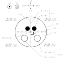
次に、本体部10の収納空間11における接続部100と下方流路82の配置関係について、図7および図8を用いて説明する。図7は、図2におけるC-C‘線での模式的断面図である。図8は、図2におけるC-C’線での模式的断面斜視図である。
Next, the positional relationship between the
本体部10の収納空間11は、機能部50が取り付けられる高さ位置において、本体部10の高さ方向(上下方向)に延びる仮想軸120の中心である仮想軸中心点130を中心に90度ごとに第1区画131、第2区画132、第3区画133、第4区画134の4つの区画に仮想線121で区画される。
The storage space 11 of the
接続部100の第1接続部材101は、機能部50が設けられている高さ位置において、第1区画131に設けられ、接続部100の第2接続部材102は、第2区画132に位置する。下方流路82は、機能部50が設けられている高さ位置において、第3区画133及び第4区画134に位置する。具体的には、下方流路82の水石鹸ホース83が、第3区画133に位置し、下方流路82の空気ホース84が第4区画134に位置する。または、水石鹸ホース83が、第4区画134に位置し、空気ホース84が第3区画133に位置してもよい。または、第3区画133と第4区画134の両方に水石鹸ホース83と空気ホース84が位置してもよい。換言すると、接続部100の第1接続部材101と第2接続部材102と、下方流路82が、それぞれ別の区画に配置される。
なお、下方流路82は、第3区画133または第4区画134の一方にのみ位置してもよい。
The
The
次に、保持部材70の詳細について、図9を用いて説明する。図9は、本発明の実施の形態に係る自動水石鹸供給装置の保持部材の斜視図である。
Next, the details of the holding
保持部材70は、センサ60を取り付けるセンサ取り付け部73と、センサ取り付け部73に取り付けられたセンサ60を保持固定する爪部72と、センサ取り付け部73の両側に形成されるガイド部71と、を有する。
保持部材70が本体部10の収納空間11に取り付けられる際に、保持部材70のセンサ取り付け部73は、センサ60がセンサ窓30の裏側に位置するように取り付けられる。
The holding
When the holding
保持部材70のガイド部71は、接続部100を固定部110まで誘導する。ガイド部71は、水平方向(左右方向)において、第1接続部材101および第2接続部材102がセンサ60を挟む位置となるように第1接続部材101および第2接続部材102をそれぞれ支持する。ガイド部71は、上下方向に貫通する貫通孔で形成される。この貫通孔は、接続部100の径よりも大きい径の孔である。そのため、接続部100が、ガイド部71を通過する際に螺合されず、接続部100が、ガイド部71を通過して、固定部110まで誘導されやすくなる。また、本実施例において、ガイド部71は貫通孔で形成されるが、接続部100の側面を完全に覆う形状でなくてもよく、例えば、使用材料削減のために全体もしくは一部に切り欠き溝の部分が形成されてもよい。また、ガイド部は保持部材の上端から下端まで形成されている孔であってもよいし、保持部材の一部にだけ設けられてもよい。
The
保持部材70は、収納空間11に取り付けられる。保持部材70は、収納空間11において、保持部材70の位置がずれることを抑制する突起部74を有する。さらに、保持部材70は、収納空間11内に取り付けられる混合室部87に対し、ねじ固定可能な、ねじ取り付け部75を有する。
保持部材70のガイド部71には接続部100が挿入され、接続部100と固定部110が接続される。この接続よりも前に、保持部材70は収納空間11の内部に取り付けられる。保持部材70の突起部74は、収納空間11に取り付けられる下方流路82に引っ掛かり、収納空間11の内部において、保持部材70の位置がずれることを抑制する。なお、突起部74は、収納空間内に形成された段差や、収納空間に取り付けられる機能部に当接し、保持部材70の位置がずれることを抑制可能な形状に形成されてもよい。
The holding
The connecting
さらに、保持部材70は、収納空間11の内部において、混合室部と固定されるねじ取り付け部75を有する。ねじ取り付け部75と、収納空間11の内部に取り付けられる混合室部87に設けられるねじ穴(図示せず)とが、ねじ(図示せず)によって螺合固定される。これにより、保持部材70は収納空間11の内部に取り付けられる混合室部87を介して、収納空間11に固定される。これにより、収納空間11において、保持部材70の位置がずれることなく固定されることで、ガイド部71に接続部100を挿入しやすく、さらに接続部100を固定部110に接続しやすくなる。
Furthermore, the holding
次に、本発明の作用効果について課題等を含めて説明する。
自動水石鹸供給装置4は水回り製品であり、水垢などの汚れが付着するため、頻繁に拭き掃除される。自動水石鹸供給装置4の中でも、本体部10は洗面台1から上方に延びる形状のため、清掃等で本体部10の上部に力が加わると、てこの原理によって本体部10と支持部40を固定する固定部110と接続部100に対し、より大きな負荷が加わる。よって、清掃のたびに、接続部100と固定部110の固定強度は、拭き掃除等の負荷に耐えられる固定強度が必要となる。
Next, the effects of the present invention will be described, including problems to be solved.
The automatic
接続部100と固定部110の固定強度は、接続部100と固定部110の材質や大きさによって担保されるが、材質の改善には開発コストがかかるため、従来は、接続部と固定部の大きさを大きくすることで負荷に耐えることのできる固定強度を実現していた。この状況下において、自動水石鹸供給装置はデザイン性を向上するために、本体部の胴回りを細くし、スリム化されることが検討された。
The strength of the
しかし、本体部の胴回りを細くし、スリム化することと同時に、本体部の内部に形成される固定部の大きさを維持することが困難であった。具体的に、固定部は、本体部の内部の収納空間の入り口において、収納空間の内側に向かって突出するように設けられていた。固定部の大きさは固定強度を低下させないため、固定部の大きさを小さくすることはできなかった。この状況下において、本体部のスリム化に伴って収納空間もスリム化されると、本体部の内部の収納空間の入り口で固定部が相対的に大きくなる。これにより、収納空間の内部に機能部を取り付ける際に、本体部の内部の収納空間の入り口は相対的に狭くなり、固定部が機能部の取り付けを妨げてしまう場合があった。 However, it was difficult to maintain the size of the fixing part formed inside the main body part while thinning and slimming the girth of the main body part. Specifically, the fixing part was provided at the entrance of the storage space inside the main body part so as to protrude toward the inside of the storage space. The size of the fixing part could not be reduced because it did not reduce the fixing strength. Under these circumstances, when the storage space was also slimmed down in conjunction with the slimming of the main body part, the fixing part became relatively large at the entrance of the storage space inside the main body part. As a result, when attaching a functional part inside the storage space, the entrance of the storage space inside the main body part became relatively narrow, and the fixing part sometimes hindered the attachment of the functional part.
解決手段の一つとして、固定部を下方に設けたまま、自動水石鹸供給装置の本体部の上方から機能部を取り付け、本体部の機能部が露出しないように蓋を設ける仕様も考えられる。しかし、蓋と本体部との接続により境界線ができ、デザイン性が低下する問題があった。 One possible solution would be to leave the fixed part at the bottom and attach the functional part from above the main body of the automatic liquid soap dispenser, then provide a lid so that the functional part of the main body is not exposed. However, there is a problem in that the connection between the lid and the main body creates a boundary line, which reduces the design.
このような、デザイン性を維持するために本体部の下方から機能部を取り付ける状況下において、固定強度を維持したまま、本体部の胴回りを細くすることは困難であった。 In this situation where the functional part is attached from below the main body in order to maintain the design, it was difficult to reduce the circumference of the main body while maintaining the fixing strength.
本発明は、本体部10の下方から機能部50を取り付ける状況下において、デザイン性と固定強度の両立を可能とするものである。具体的に、従来の固定部は本体部の内部の収納空間の入り口に設けられていたのに対し、本発明では、使用者の手を検知した際に水石鹸を吐出する自動水石鹸供給装置4において、上方に向かって延び、下方を入り口とする収納空間11が内部に形成された本体部10と、本体部10の下方から収納空間11内に設置され、少なくとも手を検知するセンサ60を有する機能部50と、洗面台1に固定される支持部40と、本体部10の内部に形成された固定部110と、固定部110と支持部40とに接続される接続部100と、を備え、固定部110は、機能部50より上方に設けられていることを特徴とする。
The present invention makes it possible to achieve both design and fixing strength when the
このように構成された本件発明によれば、本体部10の内部に、固定強度を維持できる大きさの固定部100を設けた場合であっても、本体部10の内部に形成される収納空間11の入り口部12において、機能部50の取り付けが固定部110によって妨げられることなく、且つ、機能部50と固定部110とが水平方向にオーバーラップすることがないことから本体部10の胴回りを細くすることができる。よって、デザイン性と固定強度を低下させることなく、自動水石鹸供給装置4であっても本体部10の胴回りを細くでき、スタイリッシュな自動水石鹸供給装置4を提供することができる。
According to the present invention configured in this manner, even if a fixing
また、本発明では、本体部10は、吐出口21を有するスパウト部20と、スパウト部20に水石鹸を送るための内部流路80と、を有し、内部流路80は、スパウト部20に接続され、略水平に延びる水平流路81と、水平流路81に接続され、下方に延びる下方流路82と、を有し、固定部110は、水平流路81より下方に設けられている。
In addition, in the present invention, the
このように構成された本件発明によれば、本体部10の内部に形成される固定部110は水平流路81の下方に設けられ、接続部100は本体部10の下方から固定部110に接続されることから、固定部110と接続部100が水平流路81に干渉することを避けることができ、本体部10の内部において、デッドスペースを削減しつつ、固定部110と水平流路81の配置が可能となる。よって、本体部10の胴回りを更に細くすることができる。
According to the present invention configured in this way, the fixing part 110 formed inside the
また、本件発明では、本体部10の収納空間11は、機能部50が設けられている高さ位置において、本体部10の高さ方向に延びる軸を中心に90度ごとに第1区画131、第2区画132、第3区画133、第4区画134に区画され、接続部100は、機能部50が設けられている高さ位置において、第1区画131に設けられた第1接続部材101と、第2区画132に設けられた第2接続部材102と、を有し、下方流路82は、機能部50が設けられている高さ位置において、第3区画133または第4区画134に位置していることを特徴とする。
In addition, in the present invention, the storage space 11 of the
このように構成された本件発明によれば、第1区画131に設けられた第1接続部材101と、第2区画132に設けられた第2接続部材102の2部材より、固定強度を高めることができる。また、本体部10の高さ方向に延びる軸を中心に90度ごとに区画された区画に対して、第1接続部材101と第2接続部材102と下方流路82とが区画ごとに配置されることから、限られた広さである本体部10の内部において、デッドスペースを削減しつつ、接続部100と下方流路82の配置が可能になる。よって、固定強度を低下させることなく、本体部10の胴回りをさらに細くすることができる。
According to the present invention configured in this way, the fixing strength can be increased by two members, the first connecting
また、本件発明によれば、機能部50は、センサ60を内部に保持する保持部材70を有し、保持部材70は、固定部110まで接続部100を誘導するためのガイド部71が設けられていることを特徴とする。
Furthermore, according to the present invention, the
本件発明において、本体部10の胴回りを細くするために、固定部110は機能部50よりも上方に設けられた。これにより、固定部110は本体部10の下方に形成される収納空間11の入り口部12から遠ざかった位置に設けられる。よって、接続部100が固定部110に固定される際に、固定作業を行う作業者から見えにくくなり、接続部100の固定部110に対する取り付け作業性が悪化するという特有の課題が生まれた。本件発明は、この特有の課題である取り付け作業性の悪化を防止できたものである。具体的には、保持部材70に固定部110まで接続部100を誘導するためのガイド部71が設けられる。これにより、接続部100を固定部110に固定する際に、見え難い作業であってもガイド部71に沿って接続部100を挿入するだけで接続部100は固定部110に誘導される。また、保持部材70とガイド部71が共通の部材であるため、ガイド部71が、保持部材70と別部材として配置される場合と比べて、本体部10の胴回りを細くすることができつつ、接続部100の固定部110に対する取り付け作業性の悪化を防止できる。
In the present invention, in order to reduce the girth of the
また、本件発明によれば、接続部100は、第1接続部材101と、第2接続部材102と、を有し、ガイド部71は、水平方向において、第1接続部材101および第2接続部材102がセンサ60を挟む位置となるように第1接続部材101および第2接続部材102を支持することを特徴とする。
Furthermore, according to the present invention, the
このように構成された本件発明によれば、ガイド部71をセンサ60の位置決め手段として兼用でき、本体部10の胴回りをさらに細くすることができる。また、接続部100が第1接続部材101と第2接続部材102の2部材設けられることによって、センサ60が傾きにくく、固定強度を低下させることなく、適切な位置にセンサ60の照射範囲を設定しやすくなる。
According to the present invention configured in this way, the
なお、本実施例において、図1を参照すると、自動水石鹸供給装置4が固定される洗面台1がカウンター(図示せず)と、洗面ボウル3を有する場合、自動水石鹸供給装置4はカウンター(図示せず)に固定されてもよいし、洗面ボウル3に固定されてもよい。さらに、洗面台1が鏡や壁を有する場合、自動水石鹸供給装置4は鏡に固定されてもよいし、壁に固定されてもよい。
In this embodiment, referring to FIG. 1, if the
また、保持部材70は支持部40と別体に形成されたものが図示されているが、保持部材70と支持部40は一体に形成されてもよい。また、保持部材70はガイド部71が2つ設けられているが、その限りでなく、1つのみガイド部71が設けられてもよい。
In addition, while the holding
1 洗面台
2 水栓
3 洗面ボウル
4 自動水石鹸供給装置
6 取り付け孔
10 本体部
11 収納空間
12 入り口部
13 上方部
14 下方部
20 スパウト部
21 吐出口
30 センサ窓
40 支持部
41 ねじ山
42 頭部
43 取り付け穴
44 パッキン
45 クッションパッキン
46 スリップワッシャー
47 つば付きナット
50 機能部
60 センサ
70 保持部材
71 ガイド部
72 爪部
73 センサ取り付け部
74 突起部
75 ねじ取り付け部
80 内部流路
81 水平流路
82 下方流路
83 水石鹸ホース
84 空気ホース
87 混合室部
90 台座
100 接続部
101 第1接続部材
102 第2接続部材
110 固定部
111 第1固定部
112 第2固定部
120 仮想軸
121 仮想線
130 仮想軸中心点
131 第1区画
132 第2区画
133 第3区画
134 第4区画
1
Claims (3)
上方に向かって延び、下方を入り口とする収納空間が内部に形成された本体部と、
前記本体部の下方から前記収納空間内に設置され、少なくとも手を検知するセンサを有
する機能部と、
洗面台に固定される支持部と、
前記本体部の内部に形成された固定部と、
前記固定部と前記支持部とに接続される接続部と、
を備え、
前記本体部は、吐出口を有するスパウト部と、前記スパウト部に水石鹸を送るための内部流路と、を有し、
前記内部流路は、
前記スパウト部に接続され、略水平に延びる水平流路と、
前記水平流路に接続され、下方に延びる下方流路と、を有し、
前記本体部の前記収納空間は、前記機能部が設けられている高さ位置において、前記本体部の高さ方向に延びる軸を中心に90度ごとに第1区画、第2区画、第3区画、第4区画に区画され、
前記接続部は、前記機能部が設けられている高さ位置において、前記第1区画に設けられた第1接続部材と、前記第2区画に設けられた第2接続部材と、を有し、
前記下方流路は、前記機能部が設けられている高さ位置において、前記第3区画または前記第4区画に位置しており、
前記固定部は、前記機能部より上方、且つ、前記水平流路より下方に設けられていることを特徴とする自動水石鹸供給装置。 In an automatic liquid soap dispenser that dispenses liquid soap when detecting a user's hands,
A main body portion extending upward and having a storage space formed therein with an entrance at a lower portion;
a functional unit that is installed in the storage space from below the main body and has a sensor that detects at least a hand;
A support part fixed to the washbasin;
A fixing portion formed inside the main body portion;
a connection portion connected to the fixing portion and the support portion;
Equipped with
The main body has a spout portion having a discharge port and an internal flow path for sending liquid soap to the spout portion,
The internal flow path is
A horizontal flow path connected to the spout portion and extending substantially horizontally;
a downward flow passage connected to the horizontal flow passage and extending downward,
The storage space of the main body is divided into a first section, a second section, a third section, and a fourth section at 90° intervals around an axis extending in the height direction of the main body at a height position where the functional section is provided,
the connection portion includes a first connection member provided in the first section and a second connection member provided in the second section at a height position where the functional portion is provided,
The downward flow path is located in the third section or the fourth section at a height position where the functional section is provided,
An automatic liquid soap dispenser characterized in that the fixed portion is located above the functional portion and below the horizontal flow path .
前記保持部材は、前記固定部まで前記接続部を誘導するためのガイド部が設けられていることを特徴とする請求項1に記載の自動水石鹸供給装置。 the functional unit has a holding member that holds the sensor therein,
2. The automatic liquid soap dispenser according to claim 1 , wherein the holding member is provided with a guide portion for guiding the connecting portion to the fixing portion.
前記ガイド部は、水平方向において、前記第1接続部材および前記第2接続部材が前記センサを挟む位置となるように前記第1接続部材および前記第2接続部材を支持することを特徴とする請求項2に記載の自動水石鹸供給装置。 The connection portion includes a first connection member and a second connection member,
The automatic water soap dispenser as described in claim 2, characterized in that the guide portion supports the first connecting member and the second connecting member so that the first connecting member and the second connecting member are positioned in a horizontal direction to sandwich the sensor.
Priority Applications (1)
| Application Number | Priority Date | Filing Date | Title |
|---|---|---|---|
| JP2021041083A JP7621605B2 (en) | 2021-03-15 | 2021-03-15 | Automatic water soap dispenser |
Applications Claiming Priority (1)
| Application Number | Priority Date | Filing Date | Title |
|---|---|---|---|
| JP2021041083A JP7621605B2 (en) | 2021-03-15 | 2021-03-15 | Automatic water soap dispenser |
Publications (2)
| Publication Number | Publication Date |
|---|---|
| JP2022140976A JP2022140976A (en) | 2022-09-29 |
| JP7621605B2 true JP7621605B2 (en) | 2025-01-27 |
Family
ID=83402725
Family Applications (1)
| Application Number | Title | Priority Date | Filing Date |
|---|---|---|---|
| JP2021041083A Active JP7621605B2 (en) | 2021-03-15 | 2021-03-15 | Automatic water soap dispenser |
Country Status (1)
| Country | Link |
|---|---|
| JP (1) | JP7621605B2 (en) |
Citations (2)
| Publication number | Priority date | Publication date | Assignee | Title |
|---|---|---|---|---|
| JP2002146867A (en) | 2000-11-14 | 2002-05-22 | San-Ei Faucet Mfg Co Ltd | Hand wash |
| JP2006271404A (en) | 2005-03-25 | 2006-10-12 | Toto Ltd | Water soap dispenser |
-
2021
- 2021-03-15 JP JP2021041083A patent/JP7621605B2/en active Active
Patent Citations (2)
| Publication number | Priority date | Publication date | Assignee | Title |
|---|---|---|---|---|
| JP2002146867A (en) | 2000-11-14 | 2002-05-22 | San-Ei Faucet Mfg Co Ltd | Hand wash |
| JP2006271404A (en) | 2005-03-25 | 2006-10-12 | Toto Ltd | Water soap dispenser |
Also Published As
| Publication number | Publication date |
|---|---|
| JP2022140976A (en) | 2022-09-29 |
Similar Documents
| Publication | Publication Date | Title |
|---|---|---|
| JP2011256529A (en) | Sanitary washing device | |
| JP6579373B2 (en) | Toilet device | |
| JP6090640B2 (en) | Bathroom vanity | |
| JP7621605B2 (en) | Automatic water soap dispenser | |
| KR101663101B1 (en) | Faucet for discharging hand sanitizer | |
| JP6921379B2 (en) | Toilet bowl device | |
| JPH1014794A (en) | Washing and dressing stand | |
| JP6493806B2 (en) | bathroom | |
| JP2008231888A (en) | Wall faucet fixing structure | |
| KR102341283B1 (en) | Faucets with lightweight construction | |
| JP6802518B2 (en) | Flush toilet | |
| JP6489506B2 (en) | bathroom | |
| JP6066161B2 (en) | Bathroom vanity | |
| JP6493805B2 (en) | bathroom | |
| JPH07158129A (en) | Shower faucet | |
| KR101117488B1 (en) | a faucet | |
| KR101779578B1 (en) | lavatory faucet with Shelf type | |
| JP2007016454A (en) | Ingress water discharge structure of faucet stand and draining member of faucet stand | |
| JP2008082002A (en) | Shower head support device | |
| JPH1136403A (en) | Draining device | |
| JP2004255028A (en) | Bathroom cabinet | |
| JP4715597B2 (en) | Washbasin | |
| JP5685729B2 (en) | Hand washing machine | |
| JP2001336189A (en) | Mixing faucet with hand shower | |
| JP6804039B2 (en) | Hand wash for toilet tank |
Legal Events
| Date | Code | Title | Description |
|---|---|---|---|
| A621 | Written request for application examination |
Free format text: JAPANESE INTERMEDIATE CODE: A621 Effective date: 20240112 |
|
| A977 | Report on retrieval |
Free format text: JAPANESE INTERMEDIATE CODE: A971007 Effective date: 20240627 |
|
| A131 | Notification of reasons for refusal |
Free format text: JAPANESE INTERMEDIATE CODE: A131 Effective date: 20240716 |
|
| A521 | Request for written amendment filed |
Free format text: JAPANESE INTERMEDIATE CODE: A523 Effective date: 20240917 |
|
| TRDD | Decision of grant or rejection written | ||
| A01 | Written decision to grant a patent or to grant a registration (utility model) |
Free format text: JAPANESE INTERMEDIATE CODE: A01 Effective date: 20241216 |
|
| A61 | First payment of annual fees (during grant procedure) |
Free format text: JAPANESE INTERMEDIATE CODE: A61 Effective date: 20241229 |
|
| R150 | Certificate of patent or registration of utility model |
Ref document number: 7621605 Country of ref document: JP Free format text: JAPANESE INTERMEDIATE CODE: R150 |