JP7625548B2 - 真空ポンプ - Google Patents
真空ポンプ Download PDFInfo
- Publication number
- JP7625548B2 JP7625548B2 JP2022038281A JP2022038281A JP7625548B2 JP 7625548 B2 JP7625548 B2 JP 7625548B2 JP 2022038281 A JP2022038281 A JP 2022038281A JP 2022038281 A JP2022038281 A JP 2022038281A JP 7625548 B2 JP7625548 B2 JP 7625548B2
- Authority
- JP
- Japan
- Prior art keywords
- bolt
- axial force
- vacuum pump
- spacer
- outer cylinder
- Prior art date
- Legal status (The legal status is an assumption and is not a legal conclusion. Google has not performed a legal analysis and makes no representation as to the accuracy of the status listed.)
- Active
Links
Images


Classifications
-
- F—MECHANICAL ENGINEERING; LIGHTING; HEATING; WEAPONS; BLASTING
- F04—POSITIVE - DISPLACEMENT MACHINES FOR LIQUIDS; PUMPS FOR LIQUIDS OR ELASTIC FLUIDS
- F04D—NON-POSITIVE-DISPLACEMENT PUMPS
- F04D19/00—Axial-flow pumps
- F04D19/02—Multi-stage pumps
- F04D19/04—Multi-stage pumps specially adapted to the production of a high vacuum, e.g. molecular pumps
- F04D19/042—Turbomolecular vacuum pumps
-
- F—MECHANICAL ENGINEERING; LIGHTING; HEATING; WEAPONS; BLASTING
- F04—POSITIVE - DISPLACEMENT MACHINES FOR LIQUIDS; PUMPS FOR LIQUIDS OR ELASTIC FLUIDS
- F04D—NON-POSITIVE-DISPLACEMENT PUMPS
- F04D29/00—Details, component parts, or accessories
- F04D29/40—Casings; Connections of working fluid
- F04D29/403—Casings; Connections of working fluid especially adapted for elastic fluid pumps
-
- F—MECHANICAL ENGINEERING; LIGHTING; HEATING; WEAPONS; BLASTING
- F04—POSITIVE - DISPLACEMENT MACHINES FOR LIQUIDS; PUMPS FOR LIQUIDS OR ELASTIC FLUIDS
- F04D—NON-POSITIVE-DISPLACEMENT PUMPS
- F04D29/00—Details, component parts, or accessories
- F04D29/40—Casings; Connections of working fluid
- F04D29/52—Casings; Connections of working fluid for axial pumps
- F04D29/522—Casings; Connections of working fluid for axial pumps especially adapted for elastic fluid pumps
-
- F—MECHANICAL ENGINEERING; LIGHTING; HEATING; WEAPONS; BLASTING
- F04—POSITIVE - DISPLACEMENT MACHINES FOR LIQUIDS; PUMPS FOR LIQUIDS OR ELASTIC FLUIDS
- F04D—NON-POSITIVE-DISPLACEMENT PUMPS
- F04D29/00—Details, component parts, or accessories
- F04D29/60—Mounting; Assembling; Disassembling
- F04D29/64—Mounting; Assembling; Disassembling of axial pumps
- F04D29/644—Mounting; Assembling; Disassembling of axial pumps especially adapted for elastic fluid pumps
-
- F—MECHANICAL ENGINEERING; LIGHTING; HEATING; WEAPONS; BLASTING
- F05—INDEXING SCHEMES RELATING TO ENGINES OR PUMPS IN VARIOUS SUBCLASSES OF CLASSES F01-F04
- F05D—INDEXING SCHEME FOR ASPECTS RELATING TO NON-POSITIVE-DISPLACEMENT MACHINES OR ENGINES, GAS-TURBINES OR JET-PROPULSION PLANTS
- F05D2260/00—Function
- F05D2260/30—Retaining components in desired mutual position
- F05D2260/31—Retaining bolts or nuts
-
- F—MECHANICAL ENGINEERING; LIGHTING; HEATING; WEAPONS; BLASTING
- F05—INDEXING SCHEMES RELATING TO ENGINES OR PUMPS IN VARIOUS SUBCLASSES OF CLASSES F01-F04
- F05D—INDEXING SCHEME FOR ASPECTS RELATING TO NON-POSITIVE-DISPLACEMENT MACHINES OR ENGINES, GAS-TURBINES OR JET-PROPULSION PLANTS
- F05D2260/00—Function
- F05D2260/30—Retaining components in desired mutual position
- F05D2260/38—Retaining components in desired mutual position by a spring, i.e. spring loaded or biased towards a certain position
Landscapes
- Engineering & Computer Science (AREA)
- Mechanical Engineering (AREA)
- General Engineering & Computer Science (AREA)
- Non-Positive Displacement Air Blowers (AREA)
Description
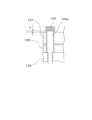
次に、軸力低減手段の変形例1について説明する。変形例1に係る軸力低減手段は、第2ボルト116の頭部116aと外筒127のボルト締結面127bとの間に隙間Cが形成されるように、第2ボルト116の呼び長さLを長くした構成に特徴がある。図8を参照して詳しく説明する。図8は、変形例1に係る第2ボルト116の締結部分の要部拡大図である。
次に、軸力低減手段の変形例2について説明する。変形例2では、スペーサ117に替えてストッパ118を軸力低減手段として用いた点に特徴がある。図9を参照して詳しく説明する。図9は、変形例2に係る第2ボルト116の締結部分の要部拡大図である。
次に、軸力低減手段の変形例3について説明する。変形例3では、ストッパ118を軸力低減手段として用いていることに加えて、隙間Cに皿バネ159を複数枚配置した点に特徴がある。図10を参照して詳しく説明する。図10は、変形例3に係る第2ボルト116の締結部分の要部拡大図である。
次に、軸力低減手段の変形例4について説明する。変形例4では、第2ボルトとして段付きボルト160を用いている点に特徴がある。図11を参照して詳しく説明する。段付きボルト160の円筒部(段部)160aは、アウターウォール126と当接するため、スペーサ117と同様の機能を有している。即ち、変形例4は、第2ボルト116とスペーサ117の構成の代わりに、第2ボルト116とスペーサ117を一体化した段付きボルト160により軸力低減手段を構成し、外筒127に軸力が作用しないようにしている。この変形例4によっても、本実施形態と同様の作用効果を奏することができる。また、スペーサ117が不要となるため、部品点数の削減及びコスト削減が期待できる。また、組立が簡単であり、作業性が向上するといった利点もある。
101 吸気口
102(102a,102b,102c) 回転翼
102d 円筒部
103 回転体
115 第1ボルト
116 第2ボルト
116a 頭部
116b ネジ部
117 スペーサ(軸力低減手段)
118 ストッパ(軸力低減手段)
122 ステータコラム
123(123a,123b、123c) 固定翼
125(125a,125b,125c) 固定翼スペーサ
126 アウターウォール(外周部品)
126a ネジ孔
127 外筒
127a 貫通孔
127b ボルト締結面
127c 凹部
128 水冷スペーサ(外周部品)
128a 貫通孔
129 ベース部
131 ネジ付スペーサ
133 排気口
159 皿バネ
160 段付きボルト(第2ボルト)
C 隙間
Claims (8)
- 回転体と、
前記回転体を収容する外筒と、
前記回転体の外周側かつ前記外筒と同軸上に配置される外周部品と、
前記外筒と前記外周部品とを締結する第1ボルト及び第2ボルトと、
前記外筒に作用するボルト軸力を低減させる軸力低減手段と、を有し、
前記軸力低減手段が、前記第2ボルトに備えられ、
前記第1ボルトの頭部が前記外筒の外面であって前記第1ボルトの頭部と対向する第1ボルト締結面と当接することにより、前記外筒及び前記外周部品に前記ボルト軸力が作用して、前記外筒と前記外周部品とが一体的に固定され、
前記軸力低減手段は、前記第2ボルトの頭部と、前記外筒の外面であって前記第2ボルトの頭部と対向する第2ボルト締結面との間に隙間を形成する構造であり、
前記隙間により、前記第2ボルトの前記ボルト軸力は前記外筒に作用しないよう構成される
ことを特徴とする真空ポンプ。 - 請求項1に記載の真空ポンプにおいて、
前記外筒には、前記第1ボルト及び前記第2ボルトが貫通する複数の貫通孔が設けられ、
前記外周部品には、前記第1ボルト及び前記第2ボルトと螺合する複数のネジ孔が設けられ、
前記複数の貫通孔の少なくとも1つには、前記軸力低減手段としての円筒状のスペーサが挿入され、
前記スペーサを介して、前記第2ボルトの頭部と前記第2ボルト締結面との間に前記隙間が形成される
ことを特徴とする真空ポンプ。 - 請求項1に記載の真空ポンプにおいて、
前記外筒には、前記第1ボルト及び前記第2ボルトが貫通する複数の貫通孔が設けられ、
前記外周部品には、前記第1ボルト及び前記第2ボルトと螺合する複数のネジ孔が設けられ、
前記第2ボルトは、前記貫通孔の長さと前記ネジ孔のネジ深さの合計値よりも大きい呼び長さで形成されることで前記軸力低減手段として機能して、前記第2ボルトの頭部と前記第2ボルト締結面との間に前記隙間を形成する
ことを特徴とする真空ポンプ。 - 請求項1に記載の真空ポンプにおいて、
前記外筒には、前記第1ボルト及び前記第2ボルトが貫通する複数の貫通孔が設けられ、
前記外周部品には、前記第1ボルト及び前記第2ボルトと螺合する複数のネジ孔が設けられ、
前記複数のネジ孔の少なくとも1つの底部には、前記軸力低減手段としてのストッパが設置され、
前記第2ボルトの先端部が前記ストッパと当接することで、前記第2ボルトの頭部と前記第2ボルト締結面との間に前記隙間が形成される
ことを特徴とする真空ポンプ。 - 請求項1~4の何れか1項に記載の真空ポンプにおいて、
前記軸力低減手段は、前記隙間に配置された弾性部材をさらに備えることを特徴とする記載の真空ポンプ。 - 請求項1~5の何れか1項に記載の真空ポンプにおいて、
前記第1ボルト及び前記第2ボルトは、それぞれ複数であり、
前記第2ボルトの本数は、前記第1ボルトの本数より少ないことを特徴とする真空ポンプ。 - 請求項1~5の何れか1項に記載の真空ポンプにおいて、
前記第1ボルト及び前記第2ボルトは、それぞれ複数であり、
前記第2ボルトの本数は、前記第1ボルトの本数より多いことを特徴とする真空ポンプ。 - 請求項1~7の何れか1項に記載の真空ポンプにおいて、
前記第1ボルトと前記第2ボルトは同一のボルトであることを特徴とする真空ポンプ。
Priority Applications (9)
| Application Number | Priority Date | Filing Date | Title |
|---|---|---|---|
| JP2022038281A JP7625548B2 (ja) | 2022-03-11 | 2022-03-11 | 真空ポンプ |
| GBGB2208031.1A GB202208031D0 (en) | 2022-03-11 | 2022-05-31 | Vacuum pump |
| TW112107488A TW202342879A (zh) | 2022-03-11 | 2023-03-02 | 真空泵 |
| KR1020247026995A KR20240157020A (ko) | 2022-03-11 | 2023-03-03 | 진공 펌프 |
| EP23766742.3A EP4491881A4 (en) | 2022-03-11 | 2023-03-03 | VACUUM PUMP |
| IL314726A IL314726A (en) | 2022-03-11 | 2023-03-03 | Vacuum pump |
| PCT/JP2023/008069 WO2023171566A1 (ja) | 2022-03-11 | 2023-03-03 | 真空ポンプ |
| US18/836,721 US12510085B2 (en) | 2022-03-11 | 2023-03-03 | Vacuum pump |
| CN202380022369.XA CN119096059A (zh) | 2022-03-11 | 2023-03-03 | 真空泵 |
Applications Claiming Priority (1)
| Application Number | Priority Date | Filing Date | Title |
|---|---|---|---|
| JP2022038281A JP7625548B2 (ja) | 2022-03-11 | 2022-03-11 | 真空ポンプ |
Publications (2)
| Publication Number | Publication Date |
|---|---|
| JP2023132764A JP2023132764A (ja) | 2023-09-22 |
| JP7625548B2 true JP7625548B2 (ja) | 2025-02-03 |
Family
ID=82324094
Family Applications (1)
| Application Number | Title | Priority Date | Filing Date |
|---|---|---|---|
| JP2022038281A Active JP7625548B2 (ja) | 2022-03-11 | 2022-03-11 | 真空ポンプ |
Country Status (9)
| Country | Link |
|---|---|
| US (1) | US12510085B2 (ja) |
| EP (1) | EP4491881A4 (ja) |
| JP (1) | JP7625548B2 (ja) |
| KR (1) | KR20240157020A (ja) |
| CN (1) | CN119096059A (ja) |
| GB (1) | GB202208031D0 (ja) |
| IL (1) | IL314726A (ja) |
| TW (1) | TW202342879A (ja) |
| WO (1) | WO2023171566A1 (ja) |
Citations (2)
| Publication number | Priority date | Publication date | Assignee | Title |
|---|---|---|---|---|
| JP2014095340A (ja) | 2012-11-09 | 2014-05-22 | Mitsubishi Heavy Ind Ltd | 排気タービンの支持構造 |
| JP2021067253A (ja) | 2019-10-28 | 2021-04-30 | エドワーズ株式会社 | 真空ポンプおよび水冷スペーサ |
Family Cites Families (15)
| Publication number | Priority date | Publication date | Assignee | Title |
|---|---|---|---|---|
| JPH06260329A (ja) | 1993-03-05 | 1994-09-16 | Toshiba Corp | 地上コイルの固定構造 |
| JP3448370B2 (ja) | 1994-10-25 | 2003-09-22 | 積水化学工業株式会社 | 溶接ロボットに適用される被溶接物のエッジ部検出方法 |
| JP2001241393A (ja) * | 1999-12-21 | 2001-09-07 | Seiko Seiki Co Ltd | 真空ポンプ |
| JP4126212B2 (ja) * | 2001-11-19 | 2008-07-30 | エドワーズ株式会社 | 真空ポンプ |
| JP2006063969A (ja) * | 2004-07-30 | 2006-03-09 | Shimadzu Corp | 回転式真空ポンプ、真空装置およびポンプ接続構造 |
| FR2893094B1 (fr) * | 2005-11-10 | 2011-11-11 | Cit Alcatel | Dispositif de fixation pour une pompe a vide |
| DE202008010092U1 (de) * | 2008-07-28 | 2009-12-10 | Sfs Intec Holding Ag | Vorrichtung zum Anschluss einer Gewindestange an Stahlteile |
| US8414258B2 (en) * | 2009-11-13 | 2013-04-09 | General Electric Company | Support bar for turbine diaphragm that facilitates reduced maintenance cycle time and cost |
| JP5832090B2 (ja) * | 2010-12-15 | 2015-12-16 | 三菱重工業株式会社 | ターボチャージャハウジングのシール構造 |
| US9745989B2 (en) * | 2012-09-24 | 2017-08-29 | Shimadzu Corporation | Turbo-molecular pump |
| DE102013109637A1 (de) * | 2013-09-04 | 2015-03-05 | Pfeiffer Vacuum Gmbh | Vakuumpumpe sowie Anordnung mit einer Vakuumpumpe |
| DE102014103510B4 (de) * | 2014-03-14 | 2016-02-25 | Pfeiffer Vacuum Gmbh | Vakuumpumpen-Dämpfer |
| US10316695B2 (en) * | 2015-12-10 | 2019-06-11 | General Electric Company | Metallic attachment system integrated into a composite structure |
| JP6934781B2 (ja) * | 2017-09-06 | 2021-09-15 | 株式会社日立インダストリアルプロダクツ | 多段遠心流体機械 |
| US11933346B1 (en) * | 2023-05-12 | 2024-03-19 | Nokia Solutions And Networks Oy | Removable shoulder screw |
-
2022
- 2022-03-11 JP JP2022038281A patent/JP7625548B2/ja active Active
- 2022-05-31 GB GBGB2208031.1A patent/GB202208031D0/en not_active Ceased
-
2023
- 2023-03-02 TW TW112107488A patent/TW202342879A/zh unknown
- 2023-03-03 US US18/836,721 patent/US12510085B2/en active Active
- 2023-03-03 WO PCT/JP2023/008069 patent/WO2023171566A1/ja not_active Ceased
- 2023-03-03 EP EP23766742.3A patent/EP4491881A4/en active Pending
- 2023-03-03 CN CN202380022369.XA patent/CN119096059A/zh active Pending
- 2023-03-03 IL IL314726A patent/IL314726A/en unknown
- 2023-03-03 KR KR1020247026995A patent/KR20240157020A/ko active Pending
Patent Citations (2)
| Publication number | Priority date | Publication date | Assignee | Title |
|---|---|---|---|---|
| JP2014095340A (ja) | 2012-11-09 | 2014-05-22 | Mitsubishi Heavy Ind Ltd | 排気タービンの支持構造 |
| JP2021067253A (ja) | 2019-10-28 | 2021-04-30 | エドワーズ株式会社 | 真空ポンプおよび水冷スペーサ |
Also Published As
| Publication number | Publication date |
|---|---|
| US12510085B2 (en) | 2025-12-30 |
| JP2023132764A (ja) | 2023-09-22 |
| KR20240157020A (ko) | 2024-10-31 |
| EP4491881A4 (en) | 2026-03-04 |
| WO2023171566A1 (ja) | 2023-09-14 |
| GB202208031D0 (en) | 2022-07-13 |
| CN119096059A (zh) | 2024-12-06 |
| TW202342879A (zh) | 2023-11-01 |
| EP4491881A1 (en) | 2025-01-15 |
| IL314726A (en) | 2024-10-01 |
| US20250163920A1 (en) | 2025-05-22 |
Similar Documents
| Publication | Publication Date | Title |
|---|---|---|
| JP7689448B2 (ja) | 真空ポンプ | |
| US20240117816A1 (en) | Vacuum pump | |
| JP7634372B2 (ja) | 真空ポンプ、回転体およびカバー部 | |
| JP7696210B2 (ja) | 真空ポンプ | |
| JP7625548B2 (ja) | 真空ポンプ | |
| JP7527266B2 (ja) | 真空ポンプ | |
| WO2025041797A1 (ja) | 真空ポンプ | |
| JP7764138B2 (ja) | 真空ポンプ | |
| KR20230116781A (ko) | 진공 펌프 | |
| JP7671586B2 (ja) | 真空ポンプとその回転体 | |
| JP7689823B2 (ja) | 真空ポンプ | |
| JP7712252B2 (ja) | 真空ポンプ | |
| JP7378447B2 (ja) | 真空ポンプおよび固定部品 | |
| JP7697983B2 (ja) | 真空ポンプ、制御装置及び昇温時間制御方法 | |
| JP7668765B2 (ja) | 真空ポンプ、制御装置および制御方法 | |
| JP7652576B2 (ja) | 真空ポンプ及びスペーサ | |
| JP7598396B2 (ja) | 真空ポンプ | |
| JP2026009478A (ja) | 真空ポンプおよびケーシング | |
| WO2022255202A1 (ja) | 真空ポンプ、スペーサ及びケーシング | |
| JP2024055254A (ja) | 真空ポンプ | |
| CN116783391A (zh) | 真空泵 |
Legal Events
| Date | Code | Title | Description |
|---|---|---|---|
| A521 | Request for written amendment filed |
Free format text: JAPANESE INTERMEDIATE CODE: A523 Effective date: 20230206 |
|
| A621 | Written request for application examination |
Free format text: JAPANESE INTERMEDIATE CODE: A621 Effective date: 20230314 |
|
| A131 | Notification of reasons for refusal |
Free format text: JAPANESE INTERMEDIATE CODE: A131 Effective date: 20240227 |
|
| A521 | Request for written amendment filed |
Free format text: JAPANESE INTERMEDIATE CODE: A523 Effective date: 20240419 |
|
| A131 | Notification of reasons for refusal |
Free format text: JAPANESE INTERMEDIATE CODE: A131 Effective date: 20240806 |
|
| A521 | Request for written amendment filed |
Free format text: JAPANESE INTERMEDIATE CODE: A523 Effective date: 20240927 |
|
| TRDD | Decision of grant or rejection written | ||
| A01 | Written decision to grant a patent or to grant a registration (utility model) |
Free format text: JAPANESE INTERMEDIATE CODE: A01 Effective date: 20250107 |
|
| A61 | First payment of annual fees (during grant procedure) |
Free format text: JAPANESE INTERMEDIATE CODE: A61 Effective date: 20250122 |
|
| R150 | Certificate of patent or registration of utility model |
Ref document number: 7625548 Country of ref document: JP Free format text: JAPANESE INTERMEDIATE CODE: R150 |