JP7626005B2 - Discharge assembly, power supply system, and power supply method - Google Patents
Discharge assembly, power supply system, and power supply method Download PDFInfo
- Publication number
- JP7626005B2 JP7626005B2 JP2021132277A JP2021132277A JP7626005B2 JP 7626005 B2 JP7626005 B2 JP 7626005B2 JP 2021132277 A JP2021132277 A JP 2021132277A JP 2021132277 A JP2021132277 A JP 2021132277A JP 7626005 B2 JP7626005 B2 JP 7626005B2
- Authority
- JP
- Japan
- Prior art keywords
- voltage
- discharge
- power
- line
- connector
- Prior art date
- Legal status (The legal status is an assumption and is not a legal conclusion. Google has not performed a legal analysis and makes no representation as to the accuracy of the status listed.)
- Active
Links
Images


Classifications
-
- B—PERFORMING OPERATIONS; TRANSPORTING
- B60—VEHICLES IN GENERAL
- B60L—PROPULSION OF ELECTRICALLY-PROPELLED VEHICLES; SUPPLYING ELECTRIC POWER FOR AUXILIARY EQUIPMENT OF ELECTRICALLY-PROPELLED VEHICLES; ELECTRODYNAMIC BRAKE SYSTEMS FOR VEHICLES IN GENERAL; MAGNETIC SUSPENSION OR LEVITATION FOR VEHICLES; MONITORING OPERATING VARIABLES OF ELECTRICALLY-PROPELLED VEHICLES; ELECTRIC SAFETY DEVICES FOR ELECTRICALLY-PROPELLED VEHICLES
- B60L1/00—Supplying electric power to auxiliary equipment of vehicles
- B60L1/006—Supplying electric power to auxiliary equipment of vehicles to power outlets
-
- B—PERFORMING OPERATIONS; TRANSPORTING
- B60—VEHICLES IN GENERAL
- B60L—PROPULSION OF ELECTRICALLY-PROPELLED VEHICLES; SUPPLYING ELECTRIC POWER FOR AUXILIARY EQUIPMENT OF ELECTRICALLY-PROPELLED VEHICLES; ELECTRODYNAMIC BRAKE SYSTEMS FOR VEHICLES IN GENERAL; MAGNETIC SUSPENSION OR LEVITATION FOR VEHICLES; MONITORING OPERATING VARIABLES OF ELECTRICALLY-PROPELLED VEHICLES; ELECTRIC SAFETY DEVICES FOR ELECTRICALLY-PROPELLED VEHICLES
- B60L53/00—Methods of charging batteries, specially adapted for electric vehicles; Charging stations or on-board charging equipment therefor; Exchange of energy storage elements in electric vehicles
- B60L53/10—Methods of charging batteries, specially adapted for electric vehicles; Charging stations or on-board charging equipment therefor; Exchange of energy storage elements in electric vehicles characterised by the energy transfer between the charging station and the vehicle
- B60L53/14—Conductive energy transfer
- B60L53/16—Connectors, e.g. plugs or sockets, specially adapted for charging electric vehicles
-
- B—PERFORMING OPERATIONS; TRANSPORTING
- B60—VEHICLES IN GENERAL
- B60L—PROPULSION OF ELECTRICALLY-PROPELLED VEHICLES; SUPPLYING ELECTRIC POWER FOR AUXILIARY EQUIPMENT OF ELECTRICALLY-PROPELLED VEHICLES; ELECTRODYNAMIC BRAKE SYSTEMS FOR VEHICLES IN GENERAL; MAGNETIC SUSPENSION OR LEVITATION FOR VEHICLES; MONITORING OPERATING VARIABLES OF ELECTRICALLY-PROPELLED VEHICLES; ELECTRIC SAFETY DEVICES FOR ELECTRICALLY-PROPELLED VEHICLES
- B60L1/00—Supplying electric power to auxiliary equipment of vehicles
- B60L1/003—Supplying electric power to auxiliary equipment of vehicles to auxiliary motors, e.g. for pumps, compressors
-
- B—PERFORMING OPERATIONS; TRANSPORTING
- B60—VEHICLES IN GENERAL
- B60L—PROPULSION OF ELECTRICALLY-PROPELLED VEHICLES; SUPPLYING ELECTRIC POWER FOR AUXILIARY EQUIPMENT OF ELECTRICALLY-PROPELLED VEHICLES; ELECTRODYNAMIC BRAKE SYSTEMS FOR VEHICLES IN GENERAL; MAGNETIC SUSPENSION OR LEVITATION FOR VEHICLES; MONITORING OPERATING VARIABLES OF ELECTRICALLY-PROPELLED VEHICLES; ELECTRIC SAFETY DEVICES FOR ELECTRICALLY-PROPELLED VEHICLES
- B60L55/00—Arrangements for supplying energy stored within a vehicle to a power network, i.e. vehicle-to-grid [V2G] arrangements
-
- H—ELECTRICITY
- H02—GENERATION; CONVERSION OR DISTRIBUTION OF ELECTRIC POWER
- H02J—ELECTRIC POWER NETWORKS; CIRCUIT ARRANGEMENTS OR SYSTEMS FOR SUPPLYING OR DISTRIBUTING ELECTRIC POWER; SYSTEMS FOR STORING ELECTRIC ENERGY
- H02J7/00—Circuit arrangements for charging or discharging batteries or for supplying loads from batteries
- H02J7/70—Circuit arrangements for charging or discharging batteries or for supplying loads from batteries characterised by the mechanical construction
-
- B—PERFORMING OPERATIONS; TRANSPORTING
- B60—VEHICLES IN GENERAL
- B60L—PROPULSION OF ELECTRICALLY-PROPELLED VEHICLES; SUPPLYING ELECTRIC POWER FOR AUXILIARY EQUIPMENT OF ELECTRICALLY-PROPELLED VEHICLES; ELECTRODYNAMIC BRAKE SYSTEMS FOR VEHICLES IN GENERAL; MAGNETIC SUSPENSION OR LEVITATION FOR VEHICLES; MONITORING OPERATING VARIABLES OF ELECTRICALLY-PROPELLED VEHICLES; ELECTRIC SAFETY DEVICES FOR ELECTRICALLY-PROPELLED VEHICLES
- B60L2210/00—Converter types
- B60L2210/10—DC to DC converters
-
- H—ELECTRICITY
- H01—ELECTRIC ELEMENTS
- H01R—ELECTRICALLY-CONDUCTIVE CONNECTIONS; STRUCTURAL ASSOCIATIONS OF A PLURALITY OF MUTUALLY-INSULATED ELECTRICAL CONNECTING ELEMENTS; COUPLING DEVICES; CURRENT COLLECTORS
- H01R31/00—Coupling parts supported only by co-operation with counterpart
- H01R31/06—Intermediate parts for linking two coupling parts, e.g. adapter
- H01R31/065—Intermediate parts for linking two coupling parts, e.g. adapter with built-in electric apparatus
-
- Y—GENERAL TAGGING OF NEW TECHNOLOGICAL DEVELOPMENTS; GENERAL TAGGING OF CROSS-SECTIONAL TECHNOLOGIES SPANNING OVER SEVERAL SECTIONS OF THE IPC; TECHNICAL SUBJECTS COVERED BY FORMER USPC CROSS-REFERENCE ART COLLECTIONS [XRACs] AND DIGESTS
- Y02—TECHNOLOGIES OR APPLICATIONS FOR MITIGATION OR ADAPTATION AGAINST CLIMATE CHANGE
- Y02T—CLIMATE CHANGE MITIGATION TECHNOLOGIES RELATED TO TRANSPORTATION
- Y02T10/00—Road transport of goods or passengers
- Y02T10/60—Other road transportation technologies with climate change mitigation effect
- Y02T10/70—Energy storage systems for electromobility, e.g. batteries
-
- Y—GENERAL TAGGING OF NEW TECHNOLOGICAL DEVELOPMENTS; GENERAL TAGGING OF CROSS-SECTIONAL TECHNOLOGIES SPANNING OVER SEVERAL SECTIONS OF THE IPC; TECHNICAL SUBJECTS COVERED BY FORMER USPC CROSS-REFERENCE ART COLLECTIONS [XRACs] AND DIGESTS
- Y02—TECHNOLOGIES OR APPLICATIONS FOR MITIGATION OR ADAPTATION AGAINST CLIMATE CHANGE
- Y02T—CLIMATE CHANGE MITIGATION TECHNOLOGIES RELATED TO TRANSPORTATION
- Y02T10/00—Road transport of goods or passengers
- Y02T10/60—Other road transportation technologies with climate change mitigation effect
- Y02T10/7072—Electromobility specific charging systems or methods for batteries, ultracapacitors, supercapacitors or double-layer capacitors
-
- Y—GENERAL TAGGING OF NEW TECHNOLOGICAL DEVELOPMENTS; GENERAL TAGGING OF CROSS-SECTIONAL TECHNOLOGIES SPANNING OVER SEVERAL SECTIONS OF THE IPC; TECHNICAL SUBJECTS COVERED BY FORMER USPC CROSS-REFERENCE ART COLLECTIONS [XRACs] AND DIGESTS
- Y02—TECHNOLOGIES OR APPLICATIONS FOR MITIGATION OR ADAPTATION AGAINST CLIMATE CHANGE
- Y02T—CLIMATE CHANGE MITIGATION TECHNOLOGIES RELATED TO TRANSPORTATION
- Y02T90/00—Enabling technologies or technologies with a potential or indirect contribution to GHG emissions mitigation
- Y02T90/10—Technologies relating to charging of electric vehicles
- Y02T90/14—Plug-in electric vehicles
Landscapes
- Engineering & Computer Science (AREA)
- Power Engineering (AREA)
- Transportation (AREA)
- Mechanical Engineering (AREA)
- Electric Propulsion And Braking For Vehicles (AREA)
- Charge And Discharge Circuits For Batteries Or The Like (AREA)
Description
本開示は、放電口に接続可能な放電コネクタを有する放電アセンブリ、給電システム、及び給電方法に関する。 The present disclosure relates to a discharge assembly having a discharge connector connectable to a discharge port, a power supply system, and a power supply method.
たとえば特許第5099281号公報(特許文献1)には、車両に搭載された蓄電装置に蓄えられた電力を車両外部へ取り出すためのコネクタ構造が開示されている。 For example, Japanese Patent Publication No. 5099281 (Patent Document 1) discloses a connector structure for extracting electricity stored in a power storage device mounted on a vehicle to the outside of the vehicle.
上記コネクタ構造では、放電口(たとえば、インレット)から単一の電力が取り出される。このため、取り出された電力によって、駆動電圧が異なる複数種の電気機器を駆動することは困難である。 In the above connector structure, a single power supply is taken from the discharge port (e.g., an inlet). For this reason, it is difficult to use the taken power to drive multiple types of electrical equipment with different drive voltages.
上記課題を解決するために、2つ以上の放電口を設け、放電口ごとに異なる電圧が出力されるようにすることも考えられる。しかし、こうした手法では、2つ以上の放電口を設けることが必須になる。こうした手法は、大きな設計変更を要求することになる。 To solve the above problem, it is possible to provide two or more discharge ports so that a different voltage is output from each discharge port. However, this method requires providing two or more discharge ports. This method requires major design changes.
本開示は、上記課題を解決するためになされたものであり、その目的は、設計変更を抑制しつつ、電圧が異なる複数種の交流電力を出力できる放電アセンブリ、給電システム、及び給電方法を提供することである。 The present disclosure has been made to solve the above problems, and its purpose is to provide a discharge assembly, a power supply system, and a power supply method that can output multiple types of AC power with different voltages while minimizing the need for design changes.
本開示の第1の観点に係る放電アセンブリは、放電口に接続可能に構成される放電コネクタを有する。放電アセンブリは、接続された放電口から電力が入力される第1端部と、第1端部から電力の供給を受け、第1電圧線、第2電圧線、及び中性線を通じて第1交流電力及び第2交流電力を出力する第2端部とを備える。放電コネクタが、放電アセンブリの第1端部を有する。第1交流電力は第1電圧線と中性線との間に第1電圧を印加する。第2交流電力は第2電圧線と中性線との間に第2電圧を印加する。放電アセンブリの第2端部は、第1コンセント及び第2コンセントを含む。第1コンセントは、第1電圧線に接続された第1電圧端子と、第2電圧線に接続された第2電圧端子と、中性線に接続されたグランド端子とを有する。第2コンセントは、第1電圧線に接続された電圧端子と、中性線に接続されたグランド端子とを有する。 The discharge assembly according to a first aspect of the present disclosure has a discharge connector configured to be connectable to a discharge port. The discharge assembly has a first end to which power is input from the connected discharge port, and a second end to which power is supplied from the first end and which outputs first AC power and second AC power through a first voltage line, a second voltage line, and a neutral line. The discharge connector has the first end of the discharge assembly. The first AC power applies a first voltage between the first voltage line and the neutral line. The second AC power applies a second voltage between the second voltage line and the neutral line. The second end of the discharge assembly includes a first outlet and a second outlet. The first outlet has a first voltage terminal connected to the first voltage line, a second voltage terminal connected to the second voltage line, and a ground terminal connected to the neutral line. The second outlet has a voltage terminal connected to the first voltage line and a ground terminal connected to the neutral line.
上記放電アセンブリでは、放電アセンブリの第2端部が第1交流電力及び第2交流電力を出力する。第1電圧線、第2電圧線、及び中性線の3線構造により、第1コンセントにおいて第1電圧線と第2電圧線との間に印加される電圧は、第1電圧と第2電圧との合計電圧になり、第2コンセントにおいて第1電圧線と中性線との間に印加される電圧は第1電圧になる。これにより、第1コンセントと第2コンセントとに異なる電圧の交流電力が出力される。上記放電アセンブリによれば、設計変更を抑制しつつ、電圧が異なる複数種の交流電力を出力することが可能になる。なお、第1電圧と第2電圧とは、同じ電圧であってもよいし、異なる電圧であってもよい。 In the above discharge assembly, the second end of the discharge assembly outputs the first AC power and the second AC power. Due to the three-wire structure of the first voltage wire, the second voltage wire, and the neutral wire, the voltage applied between the first voltage wire and the second voltage wire in the first outlet is the sum of the first voltage and the second voltage, and the voltage applied between the first voltage wire and the neutral wire in the second outlet is the first voltage. As a result, AC powers of different voltages are output to the first outlet and the second outlet. According to the above discharge assembly, it is possible to output multiple types of AC power with different voltages while suppressing design changes. Note that the first voltage and the second voltage may be the same voltage or different voltages.
上記の第1電圧線、第2電圧線、及び中性線は、第1端部から第2端部まで設けられてもよい。上記の第1交流電力及び第2交流電力は、放電口から放電アセンブリの第1端部に入力され、第1電圧線、第2電圧線、及び中性線を通じて、放電アセンブリの第2端部に伝達されてもよい。こうした構成によれば、放電アセンブリの第2端部が第1交流電力及び第2交流電力を出力しやすくなる。 The first voltage wire, the second voltage wire, and the neutral wire may be provided from the first end to the second end. The first AC power and the second AC power may be input from the discharge port to the first end of the discharge assembly, and transmitted to the second end of the discharge assembly through the first voltage wire, the second voltage wire, and the neutral wire. This configuration makes it easier for the second end of the discharge assembly to output the first AC power and the second AC power.
車両が上記放電口を備えてもよい。車両は、蓄電装置、第1電力変換回路、及び第2電力変換回路をさらに備えてもよい。第1電力変換回路及び第2電力変換回路の各々は、蓄電装置から直流電力の供給を受けて放電口側へ交流電力を出力するように構成されてもよい。放電口は、第1出力端子と、第2出力端子と、車体に接地されたグランド端子とを有してもよい。放電口における第1出力端子とグランド端子との間には、蓄電装置から第1電力変換回路を経て第1交流電力が出力されてもよい。放電口における第2出力端子とグランド端子との間には、蓄電装置から第2電力変換回路を経て第2交流電力が出力されてもよい。放電アセンブリの第1端部は、第1電圧線に接続された第1入力端子と、第2電圧線に接続された第2入力端子と、中性線に接続されたグランド端子とを含んでもよい。放電コネクタと放電口とが接続された状態においては、第1端部の第1入力端子、第2入力端子、グランド端子が、それぞれ放電口の第1出力端子、第2出力端子、グランド端子に接続されてもよい。 A vehicle may include the discharge port. The vehicle may further include a power storage device, a first power conversion circuit, and a second power conversion circuit. Each of the first power conversion circuit and the second power conversion circuit may be configured to receive DC power from the power storage device and output AC power to the discharge port. The discharge port may have a first output terminal, a second output terminal, and a ground terminal grounded to the vehicle body. Between the first output terminal and the ground terminal in the discharge port, a first AC power may be output from the power storage device via the first power conversion circuit. Between the second output terminal and the ground terminal in the discharge port, a second AC power may be output from the power storage device via the second power conversion circuit. The first end of the discharge assembly may include a first input terminal connected to the first voltage line, a second input terminal connected to the second voltage line, and a ground terminal connected to the neutral line. When the discharge connector and the discharge port are connected, the first input terminal, the second input terminal, and the ground terminal of the first end may be connected to the first output terminal, the second output terminal, and the ground terminal of the discharge port, respectively.
上記構成によれば、車両において第1電力変換回路及び第2電力変換回路によって生成される第1交流電力及び第2交流電力が、車両の放電口から放電アセンブリの第1端部(放電コネクタ)に入力される。第1電圧線と第2電圧線との間に印加される電圧を2つの電力変換回路で生成することで、1つの電力変換回路にかかる負荷が少なくなる。電力変換回路は、蓄電装置から出力される直流電力を交流電力に変換するように構成されてもよい。電力変換回路は電圧及び周波数の少なくとも一方を変換可能に構成されてもよい。電力変換回路はインバータであってもよい。 According to the above configuration, the first AC power and the second AC power generated by the first power conversion circuit and the second power conversion circuit in the vehicle are input to the first end (discharge connector) of the discharge assembly from the discharge port of the vehicle. By generating the voltage applied between the first voltage line and the second voltage line by two power conversion circuits, the load on one power conversion circuit is reduced. The power conversion circuit may be configured to convert DC power output from the power storage device into AC power. The power conversion circuit may be configured to be capable of converting at least one of the voltage and the frequency. The power conversion circuit may be an inverter.
放電アセンブリは、第1端部に接続された2線を、第1電圧線、第2電圧線、及び中性線の3線に変換する変換装置をさらに備えてもよい。第1端部と変換装置とは上記2線(たとえば、2本の電圧線)を介して電気的に接続されてもよい。変換装置と第2端部とは上記3線(第1電圧線、第2電圧線、及び中性線)を介して電気的に接続されてもよい。こうした放電アセンブリによれば、放電口から単相2線式で交流電力を受け、第2端部(コンセントを含む)へ単相3線式で交流電力を出力することが可能になる。 The discharge assembly may further include a converter that converts the two wires connected to the first end into three wires: a first voltage wire, a second voltage wire, and a neutral wire. The first end and the converter may be electrically connected via the two wires (e.g., two voltage wires). The converter and the second end may be electrically connected via the three wires (a first voltage wire, a second voltage wire, and a neutral wire). Such a discharge assembly makes it possible to receive AC power from the discharge port in a single-phase two-wire system and output AC power to the second end (including the outlet) in a single-phase three-wire system.
第2端部は第3コンセントをさらに含んでもよい。第3コンセントは、第2電圧線に接続された電圧端子と、中性線に接続されたグランド端子とを有してもよい。 The second end may further include a third outlet. The third outlet may have a voltage terminal connected to the second voltage line and a ground terminal connected to the neutral line.
上記構成によれば、第1~第3コンセントの各々に交流電力を出力できる。第3コンセントにおいて第2電圧線と中性線との間に印加される電圧は第2電圧になる。 With the above configuration, AC power can be output to each of the first to third outlets. The voltage applied between the second voltage line and the neutral line in the third outlet becomes the second voltage.
第1電圧及び第2電圧の各々は95V以上150V以下であってもよい。こうした構成によれば、駆動電圧が単相交流200V付近の電気機器の電源として第1コンセントを、駆動電圧が単相交流100V付近の電気機器の電源として第2コンセント(又は、第3コンセント)を使用できるようになる。第1コンセントにおいて第1電圧線と第2電圧線との間に印加される電圧は、第2コンセントにおいて第1電圧線と中性線との間に印加される電圧の2倍であってもよい。
The first voltage and the second voltage may each be 95V or more and 150V or less. With this configuration, the first outlet can be used as a power source for an electrical device with a drive voltage of approximately single-
放電アセンブリの第1端部は、放電口と電気的に接続された放電コネクタの要求電圧値を示すコネクタ信号を出力する検出端子を備えてもよい。 The first end of the discharge assembly may include a detection terminal that outputs a connector signal indicative of a required voltage value of the discharge connector electrically connected to the discharge port.
上記構成によれば、放電口を備える放電主体(たとえば、車両)が、放電コネクタに対応する電圧(すなわち、放電コネクタが要求する電圧)を、放電コネクタに印加しやすくなる。 The above configuration makes it easier for a discharging subject (e.g., a vehicle) equipped with a discharge port to apply a voltage corresponding to the discharge connector (i.e., the voltage required by the discharge connector) to the discharge connector.
コネクタ信号は、上記要求電圧値に加えて放電コネクタと放電口との状態を示す電位信号であってもよい。放電コネクタは、当該放電コネクタと放電口との状態に応じて検出端子の電位を変化させる検出回路をさらに備えてもよい。 The connector signal may be a potential signal indicating the state of the discharge connector and the discharge port in addition to the required voltage value. The discharge connector may further include a detection circuit that changes the potential of the detection terminal depending on the state of the discharge connector and the discharge port.
上記構成によれば、放電口を備える放電主体(たとえば、車両)が、放電コネクタと放電口との状態(たとえば、接続の有無)を認識しやすくなり、適切なタイミングで放電コネクタに電力を供給しやすくなる。 The above configuration makes it easier for a discharging entity (e.g., a vehicle) equipped with a discharge port to recognize the state (e.g., whether or not it is connected) between the discharge connector and the discharge port, making it easier to supply power to the discharge connector at the appropriate time.
中性線は検出回路を介して検出端子と電気的に接続されてもよい。コネクタ信号によって判別される状態には、未嵌合状態、嵌合状態、及び接続状態が含まれてもよい。未嵌合状態は、放電コネクタと放電口とが電気的に接続されていない状態であってもよい。嵌合状態は、放電コネクタと放電口とが電気的に接続され、かつ、放電コネクタがラッチされていない状態であってもよい。接続状態は、放電コネクタと放電口とが電気的に接続され、かつ、放電コネクタがラッチされた状態であってもよい。検出回路は、放電コネクタのラッチに連動するスイッチと、このスイッチに並列に接続された電気抵抗とを含んでもよい。 The neutral wire may be electrically connected to the detection terminal via the detection circuit. The states determined by the connector signal may include an unmated state, a mated state, and a connected state. The unmated state may be a state in which the discharge connector and the discharge port are not electrically connected. The mated state may be a state in which the discharge connector and the discharge port are electrically connected, and the discharge connector is not latched. The connected state may be a state in which the discharge connector and the discharge port are electrically connected, and the discharge connector is latched. The detection circuit may include a switch that is linked to the latch of the discharge connector, and an electrical resistor connected in parallel to the switch.
上記構成によれば、放電口と放電アセンブリの第1端部(入力端)との電気的な接続の有無に応じて検出端子の電位が変化する。また、放電コネクタのラッチの有無に応じて検出端子の電位が変化する。このため、検出端子の電位によって未嵌合状態、嵌合状態、及び接続状態を適切に判別しやすくなる。 According to the above configuration, the potential of the detection terminal changes depending on whether or not there is an electrical connection between the discharge port and the first end (input end) of the discharge assembly. In addition, the potential of the detection terminal changes depending on whether or not there is a latch on the discharge connector. This makes it easier to appropriately determine the unmated state, mated state, and connected state based on the potential of the detection terminal.
上述したいずれかの放電アセンブリにおいて、放電コネクタが、第1端部に加えて第2端部を有してもよい。 In any of the discharge assemblies described above, the discharge connector may have a second end in addition to the first end.
上記構成では、放電コネクタが第2端部(第1コンセント及び第2コンセントを含む)を有する。上記構成によれば、放電アセンブリを小型化しやすくなる。放電コネクタ単体が放電アセンブリとして機能してもよい。 In the above configuration, the discharge connector has a second end (including the first outlet and the second outlet). This configuration makes it easier to miniaturize the discharge assembly. The discharge connector alone may function as the discharge assembly.
あるいは、上述したいずれかの放電アセンブリは、放電コネクタに電気的に接続された回路を内蔵する筐体と、放電コネクタと筐体とをつなぐケーブルとをさらに備えてもよい。そして、筐体が第2端部を有してもよい。 Alternatively, any of the discharge assemblies described above may further include a housing containing a circuit electrically connected to the discharge connector, and a cable connecting the discharge connector to the housing. The housing may have a second end.
上記構成では、第1端部を有する放電コネクタと第2端部を有する筐体とがケーブルを介して接続されているため、放電口に接続可能な放電アセンブリの入力端(第1端部)と、第1コンセント及び第2コンセントを含む放電アセンブリの出力端(第2端部)とを離れた位置に配置させることが容易になる。このため、第1コンセント及び第2コンセントに関する配置の自由度が高くなる。また、放電回路の一部を筐体に収容できるため、放電コネクタを小型化しやすくなる。 In the above configuration, since the discharge connector having the first end and the housing having the second end are connected via a cable, it becomes easy to arrange the input end (first end) of the discharge assembly that can be connected to the discharge port and the output end (second end) of the discharge assembly including the first outlet and the second outlet at positions apart from each other. This increases the degree of freedom in the arrangement of the first outlet and the second outlet. In addition, since part of the discharge circuit can be accommodated in the housing, it becomes easier to miniaturize the discharge connector.
本開示の第2の観点に係る給電システムは、放電口を備える車両と、放電口に接続可能に構成される放電アセンブリとを含む。放電アセンブリは、接続された放電口から電力が入力される第1端部と、第1端部から電力の供給を受け、第1電圧線、第2電圧線、及び中性線を通じて第1交流電力及び第2交流電力を出力する第2端部とを備える。第1交流電力は第1電圧線と中性線との間に第1電圧を印加する。第2交流電力は第2電圧線と中性線との間に第2電圧を印加する。第2端部は、第1コンセント及び第2コンセントを含む。第1コンセントは、第1電圧線に接続された第1電圧端子と、第2電圧線に接続された第2電圧端子と、中性線に接続されたグランド端子とを有する。第2コンセントは、第1電圧線に接続された電圧端子と、中性線に接続されたグランド端子とを有する。車両は、蓄電装置及び電力変換回路をさらに備える。電力変換回路は、蓄電装置から電力の供給を受け、放電口へ電力を出力するように構成される。 The power supply system according to the second aspect of the present disclosure includes a vehicle having a discharge port and a discharge assembly configured to be connectable to the discharge port. The discharge assembly includes a first end to which power is input from the connected discharge port, and a second end to which power is supplied from the first end and which outputs first AC power and second AC power through a first voltage line, a second voltage line, and a neutral line. The first AC power applies a first voltage between the first voltage line and the neutral line. The second AC power applies a second voltage between the second voltage line and the neutral line. The second end includes a first outlet and a second outlet. The first outlet has a first voltage terminal connected to the first voltage line, a second voltage terminal connected to the second voltage line, and a ground terminal connected to the neutral line. The second outlet has a voltage terminal connected to the first voltage line and a ground terminal connected to the neutral line. The vehicle further includes a power storage device and a power conversion circuit. The power conversion circuit is configured to receive power from the power storage device and output power to the discharge port.
上記給電システムによっても、前述した放電アセンブリと同様、設計変更を抑制しつつ、電圧が異なる複数種の交流電力を第1コンセント及び第2コンセントから出力することが可能になる。 As with the discharge assembly described above, the power supply system makes it possible to output multiple types of AC power with different voltages from the first and second outlets while minimizing design changes.
車両は、電動車(以下、「xEV」とも称する)であってもよい。xEVは、電力を動力源の全て又は一部として利用する車両である。xEVには、BEV(電気自動車)、PHEV(プラグインハイブリッド車)、及びFCEV(燃料電池車)が含まれる。 The vehicle may be an electric vehicle (hereinafter also referred to as "xEV"). An xEV is a vehicle that uses electricity as all or part of its power source. xEVs include BEVs (electric vehicles), PHEVs (plug-in hybrid vehicles), and FCEVs (fuel cell vehicles).
本開示の第3の観点に係る給電方法は、放電口に接続された放電コネクタの要求電圧値を取得することと、放電口に接続された放電コネクタが、第1電圧線、第2電圧線、及び中性線を備える単相3線式コネクタであるか否かを判断することと、放電口に接続された放電コネクタが単相3線式コネクタである場合に、第1電圧線、第2電圧線、及び中性線に接続された第1コンセントが要求電圧値に相当する交流電圧を出力し、かつ、第1電圧線及び中性線に接続された第2コンセントが要求電圧値の2分の1に相当する交流電圧を出力するように、第1電圧線及び中性線間と第2電圧線及び中性線間との各々に交流電圧を印加することとを含む。 The power supply method according to the third aspect of the present disclosure includes acquiring a required voltage value of a discharge connector connected to a discharge port, determining whether the discharge connector connected to the discharge port is a single-phase three-wire connector having a first voltage wire, a second voltage wire, and a neutral wire, and, if the discharge connector connected to the discharge port is a single-phase three-wire connector, applying an AC voltage between the first voltage wire and the neutral wire and between the second voltage wire and the neutral wire so that a first outlet connected to the first voltage wire, the second voltage wire, and the neutral wire outputs an AC voltage equivalent to the required voltage value and a second outlet connected to the first voltage wire and the neutral wire outputs an AC voltage equivalent to half the required voltage value.
上記方法によっても、前述した放電アセンブリと同様、設計変更を抑制しつつ、電圧が異なる複数種の交流電力を第1コンセント及び第2コンセントから出力することが可能になる。 As with the discharge assembly described above, the above method also makes it possible to output multiple types of AC power with different voltages from the first and second outlets while minimizing design changes.
上記判断においては、要求電圧値が所定範囲内である場合に、放電口に接続された放電コネクタが単相3線式コネクタであると判断してもよい。また、要求電圧値が所定範囲外である場合に、放電口に接続された放電コネクタが単相3線式コネクタではないと判断してもよい。 In the above judgment, if the required voltage value is within a predetermined range, it may be judged that the discharge connector connected to the discharge port is a single-phase three-wire connector. Also, if the required voltage value is outside the predetermined range, it may be judged that the discharge connector connected to the discharge port is not a single-phase three-wire connector.
上記構成によれば、放電口に接続された放電コネクタが単相3線式コネクタであるか否かを、放電コネクタの要求電圧値に基づいて容易に判断することが可能になる。上記所定範囲は所定電圧値(一点)であってもよい。たとえば要求電圧値が200Vである場合に、放電口に接続された放電コネクタが単相3線式コネクタであると判断されてもよい。 According to the above configuration, it is possible to easily determine whether the discharge connector connected to the discharge port is a single-phase three-wire connector based on the required voltage value of the discharge connector. The above-mentioned predetermined range may be a predetermined voltage value (one point). For example, when the required voltage value is 200 V, it may be determined that the discharge connector connected to the discharge port is a single-phase three-wire connector.
本開示によれば、設計変更を抑制しつつ、電圧が異なる複数種の交流電力を出力できる放電アセンブリ、給電システム、及び給電方法を提供することが可能になる。 The present disclosure makes it possible to provide a discharge assembly, a power supply system, and a power supply method that can output multiple types of AC power with different voltages while minimizing the need for design changes.
本開示の実施の形態について、図面を参照しながら詳細に説明する。なお、図中同一又は相当部分には同一符号を付してその説明は繰り返さない。以下では、電子制御ユニット(Electronic Control Unit)を、「ECU」と称する。また、交流を「AC」、直流を「DC」と称する場合がある。 The embodiments of the present disclosure will be described in detail with reference to the drawings. Note that the same or corresponding parts in the drawings are given the same reference numerals and their description will not be repeated. Hereinafter, the electronic control unit will be referred to as "ECU." Additionally, alternating current may be referred to as "AC" and direct current as "DC."
図1は、この実施の形態に係る給電システムの全体構成図である。図1を参照して、この実施の形態に係る給電システムは、車両から電気機器に直接給電を行なうV2L(Vehicle to Load)に適用される。V2Lでは、車両用に作られた、地面に固定されていない電力変換器(たとえば、車載インバータ)により、電力系統とは別に直接電気機器へ電力の供給が行なわれる。電力系統は、電力事業者から電力使用者に電力を供給するための送配電網システム(商用電力系統)である。車載インバータは、車両に内蔵され、駆動用の車載電池の直流電力を交流電力に変換し、電気機器にAC電源を供給する装置である。 Figure 1 is an overall configuration diagram of a power supply system according to this embodiment. Referring to Figure 1, the power supply system according to this embodiment is applied to a V2L (Vehicle to Load) system that supplies power directly from a vehicle to electrical equipment. In a V2L system, a power converter (e.g., an on-board inverter) that is not fixed to the ground and is made for the vehicle supplies power directly to electrical equipment separately from the power system. The power system is a power transmission and distribution network system (commercial power system) that supplies power from a power company to power users. The on-board inverter is a device that is built into a vehicle and converts DC power from the on-board battery used for driving into AC power and supplies AC power to electrical equipment.
具体的には、この実施の形態に係る給電システムは、放電コネクタ100と、車両200とを含み、車両200から供給される電力を放電コネクタ100を通じて電力負荷300に供給するように構成される。この実施の形態では、放電コネクタ100が、第1端部P1(入力端)及び第2端部P2(出力端)を含み、放電アセンブリとして機能する。車両200としては、放電の機能を備えた任意の車両を採用可能であるが、この実施の形態では、エンジン(内燃機関)を備えない電気自動車(BEV)を車両200として採用する。
Specifically, the power supply system according to this embodiment includes a
電力負荷300は、電気機器310(機器本体)と、電気機器310につながる電源コード320とを備える。電気機器310は、電源コード320を通じて所定の交流電力の供給を受けると駆動される。放電コネクタ100は、電源コード320のプラグ321が接続可能なコンセントを備える。放電コネクタ100が備えるコンセントの詳細については後述する(図5及び図8参照)。
The
車両200は、インレット210(車両インレット)と、充放電装置220と、バッテリ230と、ECU250とを備える。インレット210、バッテリ230は、それぞれ本開示に係る「放電口」、「蓄電装置」の一例に相当する。インレット210は、放電用連結システムのうち車両200内に固定されている部分に相当する。バッテリ230は、たとえば二次電池を含む。二次電池の例としては、リチウムイオン電池又はニッケル水素電池が挙げられる。バッテリ230は、液系二次電池、全固体二次電池、組電池、及び電気二重層キャパシタからなる群より選択される1以上の蓄電装置を含んでもよい。車両200は、バッテリ230に蓄えられた電力を用いて走行可能に構成される。車両200は、バッテリ230から電力の供給を受ける電動モータ(図示せず)を備え、電動モータによって生成される動力によって走行する。
The
充放電装置220はバッテリ230を充電するように構成される。具体的には、充放電装置220は、車両外部からインレット210に供給される交流電力を直流電力に変換(AC/DC変換)し、直流電力をバッテリ230へ出力するように構成される。また、充放電装置220はバッテリ230の電力を車両外部へ放電するように構成される。具体的には、充放電装置220は、バッテリ230から供給される直流電力を交流電力に変換(DC/AC変換)し、交流電力をインレット210へ出力するように構成される。
The charging/discharging
図2は、充放電装置220周辺の構成を示す図である。図2を参照して、充放電装置220とバッテリ230との間にはSMR(System Main Relay)231が設けられている。SMR231は、充放電装置220とバッテリ230とをつなぐ電路の接続/遮断を切り替えるように構成される。インレット210とバッテリ230との間で電力の授受が行なわれるときには、ECU250によってSMR231が閉状態(接続状態)にされる。バッテリ230には、BMS(Battery Management System)232が設けられている。BMS232は、バッテリ230の状態を検出する各種センサを含み、検出結果をECU250へ出力する。ECU250は、BMS232の出力に基づいてバッテリ230の状態(たとえば、温度、電流、電圧、SOC(State Of Charge)、及び内部抵抗)を取得することができる。
2 is a diagram showing the configuration around the charging/discharging
インレット210は、車体に設けられた開口部211に配置されている。開口部211を開閉するようにリッド212が設けられている。リッド212は、開閉機構213(たとえば、ヒンジ)を介して車体と連結されることによって、開口部211を開閉可能に構成される。インレット210は、リッド212が開いた状態で使用される。リッド212が閉じた状態では、リッド212が開口部211(インレット210を含む)を覆うことにより、インレット210の使用が禁止される。この実施の形態に係るインレット210はACインレットである。すなわち、インレット210を用いてバッテリ230を充電するときには、車両外部からインレット210に交流電力が入力される。
The
ECU250は、充放電装置220を制御するように構成される。ECU250はコンピュータであってもよい。ECU250は、プロセッサ251、RAM(Random Access Memory)252、記憶装置253、及びタイマ254を備える。この実施の形態では、ECU250において記憶装置253に記憶されているプログラムをプロセッサ251が実行することで、車両200における各種制御が実行される。ただし、車両200における各種制御は、ソフトウェアによる実行に限られず、専用のハードウェア(電子回路)で実行することも可能である。なお、ECU250が備えるプロセッサの数は任意であり、所定の制御ごとにプロセッサが用意されてもよい。
The
充放電装置220は、インレット210とバッテリ230との間に、互いに並列に接続されたACインバータ221A、ACインバータ221B、及び充電器222を備える。ACインバータ221A及び221Bは、別々の筐体に収容されてもよいし、同じ筐体に一緒に収容されてもよい。ACインバータ221A、ACインバータ221Bは、それぞれ本開示に係る「第1電力変換回路」、「第2電力変換回路」の一例に相当する。
The charging/discharging
ACインバータ221Aとインレット210との間には、放電リレー223Aが設けられている。放電リレー223Aは、ACインバータ221Aからインレット210への放電経路の接続/遮断を切り替えるように構成される。また、ACインバータ221Bとインレット210との間には、放電リレー223Bが設けられている。放電リレー223Bは、ACインバータ221Bからインレット210への放電経路の接続/遮断を切り替えるように構成される。以下では、区別しない場合は、ACインバータ221A及び221Bの各々を「ACインバータ221」とも称する。
A
図3は、ACインバータ221の回路構成例を示す図である。図2とともに図3を参照して、ACインバータ221は、インバータ11~13と絶縁回路14とを含む。インバータ11~13の各々は、4つのスイッチング素子を含むフルブリッジ回路を含む。インバータ11~13のうち最もインレット210側に位置するインバータ13は、2つのリアクトルと、1つの平滑コンデンサとをさらに含む。インバータ11~13に含まれる各スイッチング素子は、ECU250によって制御される。絶縁回路14は、第1コイル14a及び第2コイル14bを含む絶縁トランスである。
Figure 3 is a diagram showing an example of the circuit configuration of
インバータ11は、バッテリ230側から入力される直流電力を高周波の交流電力に変換する。絶縁回路14は、インバータ11の出力(交流電力)をコイル巻数比に応じた比率で変圧してインバータ12に伝達する。インバータ12は、絶縁回路14から受ける交流電力を整流してインバータ13へ出力する。インバータ13は、インバータ12から受ける直流電力を所定の周波数の交流電力に変換してインレット210側に出力する。
The
上記のように、ACインバータ221は、バッテリ230側から入力される直流電力を所定の周波数の交流電力に変換してインレット210側に出力するように構成される。なお、図3に示した回路構成は一例であり、適宜変更可能である。公知の車載インバータから任意の回路構成が採用されてもよい。ACインバータ221は、バッテリ230とインレット210との間で双方向に電力変換可能に構成されてもよいし、一方向(バッテリ230からインレット210への方向)のみに電力変換可能に構成されてもよい。
As described above, the
再び図2を参照して、ACインバータ221A、221Bには、それぞれ監視ユニット224A、224Bが設けられている。監視ユニット224A、224Bは、それぞれACインバータ221A、221Bの状態(たとえば、電圧、電流、及び温度)を検出する各種センサを含み、検出結果をECU250へ出力する。ECU250は、監視ユニット224A及び224Bの出力に基づいてACインバータ221A及び221Bを制御する。これにより、各インバータからインレット210へ出力される電力(すなわち、充放電装置220の放電電力)が調整される。ECU250は、ACインバータ221A及び221Bの各々の電流を監視し、電流が所定の許容電流値(たとえば、15A)を超えそうなインバータに対して電流制限を実行するように構成されてもよい。各インバータとインレット210との間の配線の詳細については後述する(図8参照)。
Referring again to FIG. 2, the
ECU250は、放電リレー223A、223Bを遮断状態にすることによって、それぞれACインバータ221A、221Bをインレット210から切り離すことができる。この実施の形態では、放電リレーがインバータごとに設けられている。このため、各インバータを個別にインレット210から切り離すことができる。放電リレーが遮断状態になると、その放電リレーに対応するインバータからインレット210への放電が禁止される。なお、放電リレーの数は任意である。放電リレーは、複数のインバータをまとめてインレットから切り離すように配置されてもよい。
The
ACインバータ221A及び221Bの各々は、初期(たとえば、出荷時)に設定された周波数の交流電力が出力されるように交流電力の周波数を調整するように構成されてもよい。あるいは、ECU250が、地域ごとの適切な周波数の交流電力が各インバータから出力されるように、車両200の位置に基づいてACインバータ221A及び221Bを制御してもよい。ECU250は、ユーザによって任意の周波数を設定できるように構成されてもよい。
Each of the
充電器222とバッテリ230との間(より特定的には、SMR231よりも充電器222側)には、充電リレー223Cが設けられている。充電リレー223Cは、充電器222からバッテリ230への充電経路の接続/遮断を切り替えるように構成される。充電リレー223Cが遮断状態になると、インレット210から充電器222を経てバッテリ230に電力を供給することが禁止される。
A charging
図4は、充電器222の回路構成例を示す図である。図2とともに図4を参照して、充電器222は、インバータ21~23と絶縁回路24とを含む。インバータ21~23の各々は、4つのスイッチング素子を含むフルブリッジ回路を含む。インバータ21~23のうち最もインレット210側に位置するインバータ21は、フィルタ回路21aと平滑コンデンサ21bとをさらに含む。フィルタ回路21aは、交流電力に含まれる高周波ノイズを除去する。インバータ21~23に含まれる各スイッチング素子は、ECU250によって制御される。絶縁回路24は、第1コイル24a及び第2コイル24bを含む絶縁トランスである。
Figure 4 is a diagram showing an example of the circuit configuration of the
インバータ21は、インレット210側から入力される交流電力を整流してインバータ22へ出力する。インバータ22は、インバータ21から受ける直流電力を高周波の交流電力に変換する。絶縁回路24は、インバータ22の出力(交流電力)をコイル巻数比に応じた比率で変圧してインバータ23に伝達する。インバータ23は、絶縁回路24から受ける交流電力を整流してバッテリ230側に出力する。
The
上記のように、充電器222は、インレット210側から入力される交流電力を直流電力に変換してバッテリ230側に出力するように構成される。なお、図4に示した回路構成は一例であり、適宜変更可能である。充電器222は、バッテリ230とインレット210との間で双方向に電力変換可能に構成されてもよいし、一方向(インレット210からバッテリ230への方向)のみに電力変換可能に構成されてもよい。双方向に電力変換可能な充電器222は、放電用の電力変換回路として使用できる。このため、充電器222が双方向に電力変換可能に構成される形態では、ACインバータ221AとACインバータ221Bとのいずれか一方を割愛して、代わりに充電器222を用いてもよい。
As described above, the
再び図2を参照して、充電器222には監視ユニット224Cが設けられている。監視ユニット224Cは、充電器222の状態(たとえば、電圧、電流、及び温度)を検出する各種センサを含み、検出結果をECU250へ出力する。ECU250は監視ユニット224Cの出力に基づいて充電器222を制御する。これにより、充電器222からバッテリ230へ出力される電力(すなわち、バッテリ230の充電電力)が調整される。
Referring again to FIG. 2, the
図1に示した放電コネクタ100は、放電用連結システムのうちインレット210に接続される部分に相当する。以下、図5及び図6を用いて、放電コネクタ100の構造について説明する。図5は、カバー120が開いた状態の放電コネクタ100の外観を示す図である。図6は、カバー120が閉じた状態の放電コネクタ100の外観を示す図である。
The
図5及び図6を参照して、放電コネクタ100は第1端部P1及び第2端部P2を有する。第1端部P1と第2端部P2とは、放電コネクタ100の本体部110の両端に位置する。第1端部P1は、車両200のインレット210に接続可能に構成される。第2端部P2は、第1コンセントTo1、第2コンセントTo2、及び第3コンセントTo3を含む。
Referring to Figures 5 and 6, the
放電コネクタ100は、第2端部P2を開閉可能に構成されるカバー120をさらに備える。カバー120は、放電コネクタ100の本体部110に対して回動可能に取り付けられている。具体的には、カバー120は、回転機構121(たとえば、ヒンジ)を介して本体部110に取り付けられている。カバー120は、閉状態において第2端部P2を覆い、開状態において第2端部P2を露出させる。カバー120には、コード(たとえば、図1に示した電源コード320)を通す穴122が設けられている。穴122は、中心穴と、中心穴を中心に放射状に延びる複数のスリットとを含む。穴122は複数のコードを受け入れる。3本のコードを穴122に通すことで、第1~第3コンセントTo1~To3の各々に各コードのプラグが差し込まれた状態でも、カバー120を閉じることができる。カバー120が閉じた状態(図6参照)では、第1~第3コンセントTo1~To3が雨及び風にさらされることが抑制される。カバー120は防水性を有する。本体部110及びカバー120に防水処理が施されてもよい。カバー120が閉じたときにカバー120が本体部110と接触する部位にシール部材が設けられてもよい。第1~第3コンセントTo1~To3の降雨に対する保護構造は、規格「JIS C8303:2007」の6.12に規定される構造であってもよい。
The
図6に示すように、第1端部P1は、端面F1にコネクタ端子を有する。放電コネクタ100の第1端部P1の端面F1は、車両200のインレット210(図2)に接続される面(接続面)に相当する。端面F1に設けられたコネクタ端子は、端子L1と、端子L2と、端子PEと、端子CSと、端子CPとを含む。
As shown in FIG. 6, the first end P1 has a connector terminal on an end face F1. The end face F1 of the first end P1 of the
端子L1及びL2は、車両200から交流電力が入力される2つの端子に相当する。端子L1がHOT側端子であり、端子L2がCOLD側端子である。端面F1における端子L1、L2は、それぞれ本開示に係る「第1入力端子」、「第2入力端子」の一例に相当する。以下、端子L1を「AC1」、端子L2を「AC2」とも表記する。端子PEはグランド端子(以下、「GND」とも表記する)に相当する。端子CSは、放電コネクタ100とインレット210との状態(接続状態/嵌合状態/未嵌合状態)の検出(Proximity detection)のための端子(以下、「PISW」とも表記する)に相当する。以下、放電コネクタ100とインレット210との状態を、「コネクタ状態」とも称する。端子CSは、コネクタ状態を示す電位信号(以下、「PISW信号」とも称する)を車両200側に出力する。端子CS、PISW信号は、それぞれ本開示に係る「検出端子」、「コネクタ信号」の一例に相当する。端子CPは、たとえば規格「IEC/TS 62763:2013」で定義されるCPLT(Control pilot)信号のための端子(以下、「CPLT」とも表記する)に相当する。CPLT信号は、車両200と放電コネクタ100との間の通信で用いられるPWM(Pulse Width Modulation)信号である。
Terminals L1 and L2 correspond to two terminals to which AC power is input from the
インレット210は、放電コネクタ100の上記各端子(端子L1、L2、PE、CS、CP)に対応する端子を有する。以下では、双方の対応関係を明確にするため、放電コネクタ100の端子L1、L2、PE、CS、CPに対応するインレット210の端子も、AC1、AC2、GND、PISW、CPLTと称する。放電コネクタ100とインレット210とが嵌合された状態においては、放電コネクタ100の第1端部P1に設けられたAC1、AC2、GND、PISW、CPLTが、それぞれインレット210のAC1、AC2、GND、PISW、CPLTに電気的に接続される。放電コネクタ100の端子及びインレット210への嵌合構造は、たとえば規格「IEC62196-2:2011」に規定されるType1に準拠してもよい。
The
放電コネクタ100は、ラッチ解除ボタン111と、放電開始スイッチ112と、ラッチ130とをさらに備える。
The
ラッチ解除ボタン111は、インレット210に対する放電コネクタ100のラッチを解除したり、コネクタ状態(接続状態/嵌合状態/未嵌合状態)を車両200(たとえば、ECU250)に検知させたりする機能を持つ。ラッチ130は、インレット210と係合して放電コネクタ100をインレット210に固定(ラッチ)するように構成される。たとえば、インレット210に形成された凹部にラッチ130の先端が引っ掛かることによって、放電コネクタ100がラッチされる。ラッチ130はラッチ解除ボタン111に連動する。ユーザによってラッチ解除ボタン111が押されるとラッチが解除される。
The
ユーザがラッチ解除ボタン111を押さずに放電コネクタ100をインレット210に挿入して放電コネクタ100とインレット210とを嵌合させると、放電コネクタ100とインレット210とが電気的に接続された状態でラッチ130によって固定される。このコネクタ状態は、「接続状態」である。接続状態では、インレット210に放電コネクタ100が挿入され、かつ、両者の全ての端子が電気的に接続されており、かつ、放電コネクタ100がラッチされている。接続状態でユーザがラッチ解除ボタン111を押すと、ラッチ130による固定が解除される。このコネクタ状態は、「嵌合状態」である。嵌合状態では、インレット210に放電コネクタ100が挿入され、両者の全ての端子が電気的に接続されているが、放電コネクタ100がラッチされていない。嵌合状態でユーザがインレット210から放電コネクタ100を引き抜くと、コネクタ状態が「未嵌合状態」になる。未嵌合状態は、接続状態及び嵌合状態のいずれでもない状態である。コネクタ状態が接続状態又は嵌合状態であるときには、ECU250によって車両200の走行が禁止される。
When the user inserts the
放電開始スイッチ112は、PISW信号(端子CSの信号)を変化させることで車両200(たとえば、ECU250)に放電開始を検知させる機能を持つ。この実施の形態では、PISW信号が電位信号である。PISW信号の詳細については後述する(図13参照)。
The discharge start
図1に示した放電コネクタ100の第1端部P1と第2端部P2とは、単相3線式配線L10で接続されている。単相3線式配線L10は、電圧線L11と、電圧線L12と、中性線L13とを含む。電圧線L11、電圧線L12、中性線L13は、それぞれ本開示に係る「第1電圧線」、「第2電圧線」、「中性線」の一例に相当する。電圧線L11,L12及び中性線L13は、第1端部P1から第2端部P2まで設けられ、第1端部P1と第2端部P2とをつないでいる。第2端部P2は、電圧線L11,L12及び中性線L13を通じてAC100V及びAC200Vの電力を出力するように構成される。単相3線式配線L10と第1~第3コンセントTo1~To3との接続態様については後述する(図8参照)。
The first end P1 and the second end P2 of the
図7は、放電コネクタ100及びインレット210の概略的な回路構成を示す図である。図2及び図6とともに図7を参照して、放電コネクタ100において、電圧線L11、電圧線L12、中性線L13は、それぞれ第1端部P1のAC1、AC2、GNDに接続されている。放電コネクタ100の単相3線式配線L10(すなわち、電圧線L11,L12及び中性線L13)は、AC1、AC2、及びGNDを介して、車両200の単相3線式配線L20(すなわち、電圧線L21,L22及び中性線L23)と接続されている。車両200において、電圧線L21、電圧線L22、中性線L23は、それぞれインレット210のAC1、AC2、GNDに接続されている。インレット210のAC1、AC2は、それぞれ本開示に係る「第1出力端子」、「第2出力端子」の一例に相当する。車両200において、電圧線L21及びL22には、車載インバータ(たとえば、図2に示したACインバータ221A及び221B)から交流電力が供給される。そして、車載インバータから電圧線L21及びL22に供給される交流電力はAC1及びAC2を介して電圧線L11及びL12に伝達される。また、車両200において、インレット210のGNDは中性線L23を介して車体に接地されている(ボデーアース)。なお、図7には、1つのコンセントのみを示しているが、放電コネクタ100は3つのコンセント(図5に示した第1~第3コンセントTo1~To3)を備える。
7 is a diagram showing a schematic circuit configuration of the
図8は、放電コネクタ100及び車両200における単相3線式配線L10,L20の接続態様を示す図である。図2、図5、及び図7とともに図8を参照して、インレット210のAC1及びGNDはそれぞれ電圧線L21及び中性線L23を介してACインバータ221Aに接続されている。インレット210のAC2及びGNDはそれぞれ電圧線L22及び中性線L23を介してACインバータ221Bに接続されている。インレット210のGNDは、中性線L23を介して、車両200の車体に接地されている(ボデーアース)。
Figure 8 is a diagram showing the connection state of the single-phase three-wire wiring L10, L20 in the
ACインバータ221A及び221Bの各々は、バッテリ230(図2)から直流電力の供給を受けてインレット210側へ交流電力を出力するように構成される。インレット210におけるAC1とGNDとの間には、バッテリ230からACインバータ221Aを経て第1交流電力が出力される。インレット210におけるAC2とGNDとの間には、バッテリ230からACインバータ221Bを経て第2交流電力が出力される。
Each of the
放電コネクタ100の第1端部P1には、第1端部P1に接続されたインレット210から電力(たとえば、上記第1交流電力及び第2交流電力)が入力される。第1交流電力及び第2交流電力は、インレット210から第1端部P1に入力され、電圧線L11,L12及び中性線L13を通じて第2端部P2に伝達される。第2端部P2は、電圧線L11,L12及び中性線L13を通じて、第1~第3コンセントTo1~To3に第1交流電力及び第2交流電力を出力する。この実施の形態では、第1交流電力が電圧線L11と中性線L13との間にAC100Vの電圧を印加し、第2交流電力が電圧線L12と中性線L13との間にAC100Vの電圧を印加する。放電コネクタ100に関しては、電圧線L11、電圧線L12、中性線L13と電気的に接続されたコンセント端子(刃受け)をそれぞれ「L1」、「L2」、「PE」と表記する。
The first end P1 of the
図8中に示すように、第1コンセントTo1はL1(第1電圧端子)、L2(第2電圧端子)、及びPE(グランド端子)を備える。第2コンセントTo2は1つのL1(電圧端子)と2つのPE(グランド端子)とを備える。第3コンセントTo3は1つのL2(電圧端子)と2つのPE(グランド端子)とを備える。第1コンセントTo1はL1及びL2間にAC200Vを出力する。第2コンセントTo2はL1及びPE間にAC100Vを出力する。第3コンセントTo3はL2及びPE間にAC100Vを出力する。第1コンセントTo1は、定格電圧250V・定格電流20Aの単相AC200V用コンセントであってもよい。第2コンセントTo2及び第3コンセントTo3の各々は、定格電圧125V・定格電流15Aの単相AC100V用コンセントであってもよい。
As shown in FIG. 8, the first outlet To1 has L1 (first voltage terminal), L2 (second voltage terminal), and PE (ground terminal). The second outlet To2 has one L1 (voltage terminal) and two PE (ground terminals). The third outlet To3 has one L2 (voltage terminal) and two PE (ground terminals). The first outlet To1 outputs
上記のように、単相3線式配線L10によってAC100V/AC200Vを出力することができる。たとえば、図1に示した電気機器310の駆動電圧がAC200Vであれば、電源コード320を第1コンセントTo1につなぐことで、電気機器310を駆動することができる。図1に示した電気機器310の駆動電圧がAC100Vであれば、電源コード320を第2コンセントTo2又は第3コンセントTo3につなぐことで、電気機器310を駆動することができる。また、複数のコンセントを同時に使用することで、駆動電圧が異なる複数種の電気機器を駆動することも可能である。
As described above,
再び図2及び図6とともに図7を参照して、車両200においては、車体(グランド)と信号線L24との間に基準電圧が付与されており、信号線L24はPISWに接続されている。そして、PISW信号(PISW電位)は信号線L24を介してECU250に入力される。放電コネクタ100の第1端部P1とインレット210とが電気的に接続されると、PISWとGNDとが放電コネクタ100の回路(後述する検出回路140を含む)を介してつながるように閉回路(閉じた系)が形成される。これにより、PISWの電位が変化する。放電コネクタ100が電源を持っていなくても、上記閉回路によってPISW信号が生成される。ECU250は、PISW信号(PISW電位)に基づいてコネクタ状態を判別できる。
2 and 6, in the
放電コネクタ100において、PISWに接続された信号線L14は、検出回路140を介して、中性線L13に接続されている。検出回路140は、放電コネクタ100が接続状態/嵌合状態/未嵌合状態のいずれの状態であるかを判別するための回路(Proximity detection回路)である。検出回路140は、電気抵抗R1,R2,R3及びスイッチS1,S2を含む。信号線L14は、PISWから電気抵抗R1を経て2つの分岐路L141及びL142に分岐し、分岐路L141及びL142が合流して中性線L13に接続されている。電気抵抗R2は分岐路L141に配置され、電気抵抗R3及びスイッチS1は分岐路L142に配置されている。電気抵抗R2と電気抵抗R3とは並列に配置されている。電気抵抗R3とスイッチS1とは直列に配置されている。また、スイッチS2は、電気抵抗R3に対して並列に配置されている。
In the
スイッチS1、S2は、それぞれ放電コネクタ100のラッチ解除ボタン111、放電開始スイッチ112(図5及び図6)に連動して開閉する。スイッチS1は、ラッチ解除ボタン111が押されていないときには閉状態(導通状態)になり、ラッチ解除ボタン111が押されているときには開状態(遮断状態)になる。スイッチS2は、放電開始スイッチ112がOFFのときには閉状態(導通状態)になり、放電開始スイッチ112がONのときには開状態(遮断状態)になる。この実施の形態では、ユーザが放電開始スイッチ112を押している間は放電開始スイッチ112がONになり、ユーザが放電開始スイッチ112を離すと放電開始スイッチ112はOFFになる。ユーザがラッチ解除ボタン111及び放電開始スイッチ112のいずれも操作していないときには、スイッチS1及びS2は両方とも閉状態になっている。すなわち、スイッチS1及びS2の各々はノーマリオン型のスイッチに相当する。
The switches S1 and S2 are opened and closed in conjunction with the
スイッチS1,S2が開状態になると、スイッチS1,S2が閉状態のときよりも検出回路140の抵抗値(合成抵抗)が上昇し、それに伴いPISWの電位も上昇する。ECU250は、PISW信号(PISW電位)に基づいて、スイッチS1及びS2の各々の状態(ひいては、ラッチ解除ボタン111及び放電開始スイッチ112の各々の状態)を判別できる。
When switches S1 and S2 are open, the resistance value (combined resistance) of
図5及び図6に示した放電コネクタ100において、ラッチ解除ボタン111は、車両200からの放電を停止するためのスイッチとして機能し、放電開始スイッチ112は、車両200からの放電を開始するためのスイッチとして機能する。コネクタ状態が接続状態であるときにユーザが放電開始スイッチ112に所定の操作を行なうと、車両200(ECU250)が、放電開始を認識し、放電を開始する。この実施の形態では、ユーザが放電開始スイッチ112を2度ONすることにより、放電が開始される。放電中にラッチ解除ボタン111が押され、コネクタ状態が嵌合状態又は未嵌合状態になると、車両200(ECU250)が、放電停止を認識し、放電を停止する。
In the
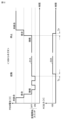
図9は、放電コネクタ100の起動(放電開始)及び停止(放電停止)のシーケンスを示すタイムチャートである。図9において、線D1はPISWの電位を示し、線D2はインレット210から放電コネクタ100側に出力される交流電力を示す。
Figure 9 is a time chart showing the sequence of starting (starting discharge) and stopping (stopping discharge) the
図5~図8とともに図9を参照して、ユーザがラッチ解除ボタン111を押しながら放電コネクタ100をインレット210に挿入すると、コネクタ状態が未嵌合状態から嵌合状態になり、PISWの電位が低下する。その後、ユーザがラッチ解除ボタン111を離すと、コネクタ状態が嵌合状態から接続状態になり、PISWの電位がさらに低下する。コネクタ状態が接続状態になってから所定時間(たとえば、500ms)経過すると、放電開始スイッチ112の操作が有効になる。そして、ユーザが放電開始スイッチ112をON状態にするとPISWの電位が上昇する。その後、ユーザが放電開始スイッチ112をOFF状態に戻すとPISWの電位も戻る。コネクタ状態が接続状態であるときに、図9に示す順序、すなわちON、OFF、ON、OFFの順序で、ユーザが放電開始スイッチ112を操作すると、ECU250(図2)が、PISWの電位に基づいて放電開始を認識し、放電を開始する。ノイズによる誤作動を抑制するため、ECU250における放電開始スイッチ112の認識は、ON/OFF操作に対応する電圧が所定時間(たとえば、50ms~3000ms)継続した場合に有効とする。
5 to 8, referring to FIG. 9, when the user inserts the
車両200からの放電はECU250によって実行される。具体的には、ECU250は、前述した第1交流電力及び第2交流電力がインレット210から放電コネクタ100側に出力されるように、充放電装置220(図2)を制御する。また、放電中はSMR231(図2)が閉状態に制御される。放電開始操作から放電開始までの期間Tsは任意に設定できる。ECU250は、期間Tsにおいて所定の処理(たとえば、断線チェックのような放電前検査)を実行してもよい。期間TsにおいてSMR231が開状態から閉状態に切り替えられてもよい。
Discharge from the
放電中にラッチ解除ボタン111が押されると、コネクタ状態が接続状態から嵌合状態になり、PISWの電位が上昇する。コネクタ状態が嵌合状態になると、ECU250が、PISWの電位に基づいて放電停止を認識し、放電を停止する。放電停止操作から放電停止までの期間Teは、規格「IEC61851-1」に規定される期間であってもよい。
When the
再び図2及び図6とともに図7を参照して、PISW信号(PISW電位)は、上述したコネクタ状態及びスイッチ状態に加えて、インレット210に電気的に接続された放電コネクタの要求電圧値も示す。詳しくは、インレット210は、複数種の放電コネクタに接続可能に構成される。この実施の形態では、図5~図9に示した放電コネクタ100に加えて、以下に説明する放電コネクタ100Aも、インレット210に接続され得る。放電コネクタ100と放電コネクタ100Aとでは、要求電圧値が異なる。放電コネクタ100の要求電圧値は200Vであり、放電コネクタ100Aの要求電圧値は100Vである。以下、放電コネクタ100、放電コネクタ100Aを、それぞれ「200Vコネクタ」、「100Vコネクタ」とも称する。この実施の形態に係る200Vコネクタは単相3線式コネクタに相当する。
2 and 6, and again referring to FIG. 7, the PISW signal (PISW potential) indicates the required voltage value of the discharge connector electrically connected to the
図10は、100Vコネクタについて説明するための図である。以下では、200Vコネクタとの相違点を中心に、100Vコネクタについて説明する。 Figure 10 is a diagram for explaining the 100V connector. Below, we will explain the 100V connector, focusing on the differences with the 200V connector.
図10を参照して、放電コネクタ100Aの外観は放電コネクタ100(図5)と概ね同じである。ただし、放電コネクタ100Aが備えるコンセントの数は1つである。放電コネクタ100Aは、ラッチ解除ボタン111Aと、放電開始スイッチ112Aとを備える。放電コネクタ100Aは、インレット210に接続可能な第1端部P1Aを有する。また、放電コネクタ100Aは、第2端部P2AにコンセントTo4を有する。
Referring to FIG. 10, the appearance of the
放電コネクタ100Aにおいては、第1端部P1AとコンセントTo4とが単相2線式配線L10Aで接続されている。単相2線式配線L10Aは、電圧線L11Aと、電圧線L12Aとを含む。電圧線L11A、電圧線L12Aは、それぞれ第1端部P1AのAC1、AC2に接続されている。この実施の形態では、放電コネクタ100Aがインレット210に接続されたことを認識したECU250が、インレット210のAC1及びAC2間に100Vの単相交流電力が出力されるように、ACインバータ221A及び221Bを制御する。
In the
放電コネクタ100Aの第1端部P1Aには、第1端部P1Aに接続されたインレット210から単相交流電力が入力される。この単相交流電力は電圧線L11Aと電圧線L12Aとの間にAC100Vの電圧を印加する。放電コネクタ100Aに関しては、電圧線L11A、電圧線L12Aと電気的に接続されたコンセント端子をそれぞれ「L1」、「L2」と表記する。
Single-phase AC power is input to the first end P1A of the
図10中に示すように、コンセントTo4は、L1、L2、及びグランド端子を備える。コンセントTo4はL1及びL2間に100Vの単相交流電力を出力する。コンセントTo4のグランド端子は、放電コネクタ100Aにおいて接地されている。コンセントTo4のグランド端子は、車両200の車体と同電位にされてもよいし、車両200の車体から絶縁された状態(フローティング状態)にされてもよい。
As shown in FIG. 10, outlet To4 has L1, L2, and a ground terminal. Outlet To4 outputs 100V single-phase AC power between L1 and L2. The ground terminal of outlet To4 is grounded at
図11は、100Vコネクタの概略的な回路構成を示す図である。図11を参照して、インレット210に放電コネクタ100Aが接続された状態ではPISWとGNDとが放電コネクタ100Aの回路(検出回路140Aを含む)を介してつながるように閉回路が形成される。車両200においては、車体(グランド)とPISWとの間に基準電圧が付与されている。このため、放電コネクタ100Aが電源を持っていなくても、上記閉回路によってPISW信号が生成される。また、放電コネクタ100Aにおいては、PISWに接続された信号線L14Aが、検出回路140Aを介して、コンセントTo4のグランド端子に接続されている。検出回路140Aは、電気抵抗R1A,R2A,R3A及びスイッチS1A,S2Aを含む。スイッチS1A、S2Aは、それぞれラッチ解除ボタン111A、放電開始スイッチ112A(図10参照)に連動して開閉する。信号線L14Aは、PISWから電気抵抗R1Aを経て2つの分岐路L141A及びL142Aに分岐し、分岐路L141A及びL142Aが合流してグランド線L13Aに接続されている。検出回路140Aは、基本的には図7に示した検出回路140に準ずる構成を有するが、以下の点で検出回路140とは異なる。
Figure 11 is a diagram showing a schematic circuit configuration of a 100V connector. With reference to Figure 11, when the
検出回路140と検出回路140Aとでは抵抗値が異なる。図7中に示されるように、検出回路140において電気抵抗R1、R2、R3はそれぞれ20Ω、460Ω、20Ωの抵抗値を有する。これに対し、検出回路140Aにおける電気抵抗R1A、R2A、R3Aは、図11中に示すように、それぞれ39Ω、430Ω、51Ωの抵抗値を有する。検出回路140及び140Aの各々における各抵抗値は、後述する電位マップM2に合わせて設定されている。また、検出回路140及び140Aに含まれる各電気抵抗は、規格「IEC61851-1:2010 AnnexB」に規定される充電コネクタ内の電気抵抗とは異なる抵抗値に設定される。こうすることで、ECU250はPISW信号(PISW電位)に基づいて充電コネクタと放電コネクタとを判別できる。
The resistance values of the
検出回路140Aにおいて、スイッチS1Aはノーマリオン型のスイッチであり、スイッチS2Aはノーマリオフ型のスイッチである。スイッチS2Aは、放電開始スイッチ112AがONのときには閉状態になり、放電開始スイッチ112AがOFFのときには開状態になる。
In the
図12は、100Vコネクタの起動(放電開始)及び停止(放電停止)のシーケンスを示すタイムチャートである。図12において、線D1AはPISWの電位を示し、線D2Aはインレット210から放電コネクタ100A側に出力される交流電力を示す。
Figure 12 is a time chart showing the sequence of starting (starting discharge) and stopping (stopping discharge) the 100V connector. In Figure 12, line D1A shows the potential of PISW, and line D2A shows the AC power output from
図10及び図11とともに図12を参照して、放電コネクタ100Aのシーケンスは、基本的には、図9に示した放電コネクタ100のシーケンスと同じである。ただし、ユーザが放電開始スイッチ112AをON状態にするとPISWの電位は下降する。ユーザが放電開始スイッチ112AをOFF状態に戻すとPISWの電位も戻る。コネクタ状態が接続状態であるときに、図12に示す順序、すなわちON、OFF、ON、OFFの順序で、ユーザが放電開始スイッチ112Aを操作すると、ECU250(図2)が、PISWの電位に基づいて放電開始を認識し、放電を開始する。
Referring to FIG. 12 along with FIG. 10 and FIG. 11, the sequence of the
図13は、PISW信号(PISW電位)について説明するための図である。図13を参照して、PISW電位に関する電位マップM1は、充電規格「IEC61851-1」に規定される電位レンジごとの判定値を示している。0~4.7Vの範囲において、電位レンジ1.359~1.639V、2.553~2.944V、4.301~4.567Vに対しては、それぞれ接続状態、嵌合状態、未嵌合状態のようなコネクタ状態が、判定値として定義されている。これら以外の電位レンジは未定義である。 Figure 13 is a diagram for explaining the PISW signal (PISW potential). Referring to Figure 13, potential map M1 for the PISW potential shows the judgment values for each potential range defined in the charging standard "IEC 61851-1". In the range of 0 to 4.7 V, connector states such as connected, mated, and unmated are defined as judgment values for the potential ranges of 1.359 to 1.639 V, 2.553 to 2.944 V, and 4.301 to 4.567 V, respectively. Potential ranges other than these are undefined.
PISW電位に関する電位マップM2は、制御で使用される制御マップであり、図2に示したECU250の記憶装置253に記憶されている。電位マップM2においては、電位レンジごとに、放電コネクタのコネクタ状態、スイッチ状態、及び要求電圧値が定められている。インレット210に対して放電コネクタが電気的に接続されたときに、ECU250は、電位マップM2を用いることで、PISW信号から上記放電コネクタのコネクタ状態、スイッチ状態、及び要求電圧値を取得できる。また、ECU250は、PISW信号に基づいて、インレット210に対して放電コネクタが電気的に接続されているか否かを判断できる。
The potential map M2 relating to the PISW potential is a control map used in control, and is stored in the
電位マップM2においては、電位レンジ0.0~1.2Vに対して、放電コネクタが接続状態であることを示す電位レンジ(以下、「接続レンジ」とも称する)が割り当てられている。電位レンジ1.2~2.0Vに対しては、充電時に使用される電位レンジ(充電レンジ)が割り当てられている。電位レンジ2.0~3.5Vに対しては、放電コネクタが嵌合状態であることを示す電位レンジ(以下、「嵌合レンジ」とも称する)が割り当てられている。電位レンジ3.5~4.7Vに対しては、放電コネクタが未嵌合状態であることを示す電位レンジ(以下、「未嵌合レンジ」とも称する)が割り当てられている。 In the potential map M2, a potential range indicating that the discharge connector is connected (hereinafter also referred to as the "connection range") is assigned to the potential range of 0.0 to 1.2 V. A potential range used during charging (charging range) is assigned to the potential range of 1.2 to 2.0 V. A potential range indicating that the discharge connector is engaged (hereinafter also referred to as the "engagement range") is assigned to the potential range of 2.0 to 3.5 V. A potential range indicating that the discharge connector is not engaged (hereinafter also referred to as the "unengaged range") is assigned to the potential range of 3.5 to 4.7 V.
電位マップM2においては、充電規格「IEC61851-1」において未定義の電位レンジ0.0~1.2Vに対して接続レンジが割り当てられている。こうすることで、ECU250が充電コネクタと放電コネクタとを判別しやすくなる。接続レンジは、以下に説明する3つの電位レンジ(0.0~0.4V/0.4~0.7V/0.7~1.2V)にさらに分割されている。
In potential map M2, a connection range is assigned to the potential range of 0.0 to 1.2 V, which is undefined in the charging standard "IEC 61851-1." This makes it easier for the
電位レンジ0.0~0.4Vに対しては、インレット210に接続された放電コネクタの要求電圧値が200Vであることを示す電位レンジ(以下、「200Vレンジ」とも称する)が割り当てられている。PISW電位が200Vレンジに属することは、インレット210に接続された放電コネクタが200Vコネクタであることを意味する。電位レンジ0.7~1.2Vに対しては、インレット210に接続された放電コネクタの要求電圧値が100Vであることを示す電位レンジ(以下、「100Vレンジ」とも称する)が割り当てられている。PISW電位が100Vレンジに属することは、インレット210に接続された放電コネクタが100Vコネクタであることを意味する。100Vコネクタ(図11)と200Vコネクタ(図7)とで抵抗値が異なることによって、各コネクタがインレット210に接続されたときのPISW電位も異なるようになる。100Vレンジ及び200Vレンジの各々は、インレット210に接続された放電コネクタの要求電圧値に加えて、当該放電コネクタの放電開始スイッチがOFF状態であることも示す。
For the potential range of 0.0 to 0.4 V, a potential range (hereinafter also referred to as the "200 V range") is assigned which indicates that the required voltage value of the discharge connector connected to the
電位レンジ0.4~0.7Vに対しては、放電開始スイッチがON状態であることを示す電位レンジ(以下、「放電開始レンジ」とも称する)が割り当てられている。200Vコネクタでは放電開始スイッチ112に連動するスイッチS2(図7)がノーマリオン型のスイッチであるため、放電開始スイッチ112がOFF状態からON状態になると、PISW電位は上昇する。100Vコネクタでは放電開始スイッチ112Aに連動するスイッチS2A(図11)がノーマリオフ型のスイッチであるため、放電開始スイッチ112AがOFF状態からON状態になると、PISW電位は下降する。
A potential range indicating that the discharge start switch is in the ON state (hereinafter also referred to as the "discharge start range") is assigned to the potential range of 0.4 to 0.7 V. In the 200 V connector, switch S2 (Fig. 7) linked to the
図14は、ECU250によって実行される放電開始に係る処理を示すフローチャートである。このフローチャートに示される処理は、車両200の停車中(ただし、充電中及び放電中を除く)において繰り返し実行される。
Figure 14 is a flowchart showing the process related to the start of discharge executed by the
図1~図13とともに図14を参照して、S101では、ECU250がPISW信号(PISW電位)を取得する。続くS102では、ECU250が、PISW信号に基づいて、インレット210に放電コネクタが接続されたか否かを判断する。コネクタ状態が接続状態になると、S102においてYESと判断され、処理がS103に進む。S103では、インレット210に接続された放電コネクタの要求電圧値が100Vと200Vとのいずれであるかを、ECU250が判断する。
Referring to FIG. 14 together with FIG. 1 to FIG. 13, in S101, the
ECU250は、図13に示した電位マップM2を用いて、S101で取得したPISW信号から、インレット210の状態(たとえば、コネクタ状態)と、インレット210に接続された放電コネクタの情報(たとえば、スイッチ状態及び要求電圧値)とを取得する。ECU250は、PISW電位が未嵌合レンジと嵌合レンジと接続レンジとのいずれに属するかに基づいて、コネクタ状態(未嵌合状態/嵌合状態/接続状態)を判別できる。また、ECU250は、PISW電位が放電開始レンジに属するか否かに基づいて、ユーザによって放電開始スイッチが操作されたか否かを判別できる。さらに、ECU250は、PISW電位が100Vレンジと200Vレンジとのいずれに属するかに基づいて、放電コネクタの要求電圧値(100V/200V)を判別できる。PISW電位が200Vレンジに属することは、インレット210に接続された放電コネクタが単相3線式コネクタ(図5~図9に示した200Vコネクタ)であることを意味する。ECU250は、インレット210に接続された放電コネクタの要求電圧値が200Vである場合に、当該放電コネクタが単相3線式コネクタであると判断する。
The
S103において放電コネクタの要求電圧値が200Vであると判断された場合には、ECU250は、S111において、ユーザによってAC200V放電開始操作(図9に示したON、OFF、ON、OFFの順の放電開始スイッチ操作)が行なわれたか否かを判断する。そして、ユーザによってAC200V放電開始操作が行なわれると(S111にてYES)、ECU250が、S112において、200Vの単相交流電力をインレット210から200Vコネクタ側に出力する。具体的には、図8に示したインレット210のAC1及びAC2間に200Vの単相交流電力が出力されるように、ECU250がACインバータ221A及び221Bを制御する。この実施の形態では、ACインバータ221A及び221Bの各々が、要求電圧値の2分の1に相当する交流電圧(AC100V)を印加することで、AC1及びAC2間にAC200Vを印加する。これにより、200Vコネクタの第1コンセントTo1、第2コンセントTo2、第3コンセントTo3に、それぞれ200V、100V、100Vの単相交流電力が出力される。
If it is determined in S103 that the required voltage value of the discharge connector is 200V, the
S103において放電コネクタの要求電圧値が100Vであると判断された場合には、ECU250は、S121において、ユーザによってAC100V放電開始操作(図12に示したON、OFF、ON、OFFの順の放電開始スイッチ操作)が行なわれたか否かを判断する。そして、ユーザによってAC100V放電開始操作が行なわれると(S121にてYES)、ECU250が、S122において、100Vの単相交流電力をインレット210から100Vコネクタ側に出力する。具体的には、図10に示したインレット210のAC1及びAC2間に100Vの単相交流電力が出力されるように、ECU250がACインバータ221A及び221Bを制御する。この実施の形態では、ACインバータ221A及び221Bの各々が、要求電圧値の2分の1に相当する交流電圧(AC50V)を印加することで、AC1及びAC2間にAC100Vを印加する。これにより、100VコネクタのコンセントTo4に100Vの単相交流電力が出力される。ただしこれに限られず、ECU250は、ACインバータ221AのみでAC1及びAC2間にAC100Vを印加し、ACインバータ221Bを電圧未印加の状態(導通状態)にしてもよい。
If it is determined in S103 that the required voltage value of the discharge connector is 100V, the
上記のS112又はS122において放電が開始されると、図14に示す一連の処理は終了する。開始された放電は、所定の放電停止条件が成立すると終了する。所定の放電停止条件が成立した場合には、ECU250が、インレット210から放電コネクタへの放電を停止させるようにACインバータ221A及び221Bを制御する。放電中にコネクタ状態が嵌合状態又は未嵌合状態になると上記放電停止条件が成立することは、前述のとおりである。また、バッテリ230のSOCが所定SOC値以下になった場合にも、上記放電停止条件は成立する。ただしこれに限られず、放電停止条件は任意に設定できる。
When discharging is started in S112 or S122, the series of processes shown in FIG. 14 ends. The started discharge ends when a predetermined discharge stop condition is met. When the predetermined discharge stop condition is met, the
以上説明したように、この実施の形態に係る給電方法は、車両200が備えるインレット210に接続された放電コネクタの要求電圧値を取得すること(S101)と、インレット210に接続された放電コネクタが単相3線式コネクタ(電圧線L11,L12及び中性線L13を備える放電コネクタ)であるか否かを判断すること(S103)と、インレット210に接続された放電コネクタが単相3線式コネクタである場合には(S103にて「200V」)、第1コンセントTo1(電圧線L11,L12及び中性線L13に接続されたコンセント)が要求電圧値に相当する交流電圧(AC200V)を出力し、かつ、電圧線L11及び中性線L13に接続された第2コンセントTo2が要求電圧値の2分の1に相当する交流電圧(AC100V)を出力し、かつ、電圧線L12及び中性線L13に接続された第3コンセントTo3が要求電圧値の2分の1に相当する交流電圧(AC100V)を出力するように、電圧線L11及び中性線L13間と電圧線L12及び中性線L13間との各々に交流電圧を印加すること(S112)とを含む。
As described above, the power supply method according to this embodiment includes obtaining the required voltage value of the discharge connector connected to the
上記給電方法によれば、既存の車両に対する設計変更を抑制しつつ、AC200Vの交流電力を第1コンセントTo1から出力し、AC100Vの交流電力を第2コンセントTo2及び第3コンセントTo3の各々から出力することが可能になる。
The above power supply method makes it possible to
放電コネクタの判別に使用される制御マップは、図13に示した電位マップM2に限られない。たとえば、ECU250は、0.0~1.2V以外の電位レンジを用いて、放電コネクタの要求電圧値を検出してもよい。より具体的には、充電規格「IEC61851-1」において未定義の電位レンジである1.639~2.553Vと2.944~4.301Vと4.567~4.700Vとのいずれかに、100Vレンジ、200Vレンジ、及び放電開始レンジを含む接続レンジを割り当ててもよい。
The control map used to determine the discharge connector is not limited to the potential map M2 shown in FIG. 13. For example, the
上記実施の形態では、単相3線式配線でAC100V/AC200Vを出力する例を示しているが、単相3線式配線で出力される電圧は適宜変更可能である。たとえば、単相3線式配線でAC110V/AC220V、AC115V/AC230V、又はAC120V/AC240Vを出力してもよい。
In the above embodiment, an example is shown in which
単相3線式コネクタの構成は、図5~図9に示した構成に限られない。たとえば第3コンセントTo3を割愛してもよい。また、カバー120を割愛してもよい。さらに、放電開始スイッチ112も割愛可能である。放電開始のトリガは任意に設定できる。たとえば、コネクタ状態が接続状態になってから所定時間が経過すると、放電が開始されてもよい。また、車両に設けられたスイッチをユーザが操作すると、放電が開始されてもよい。
The configuration of the single-phase three-wire connector is not limited to the configuration shown in Figures 5 to 9. For example, the third outlet To3 may be omitted. Also, the
単相3線式コネクタは、第1端部に接続された2線を、第1電圧線、第2電圧線、及び中性線の3線に変換する変換装置をさらに備えてもよい。図15は、図8に示した構成の変形例を示す図である。 The single-phase three-wire connector may further include a converter that converts the two wires connected to the first end into three wires: a first voltage wire, a second voltage wire, and a neutral wire. Figure 15 shows a modified example of the configuration shown in Figure 8.
図15を参照して、車両200Bはインレット210Bと交流電源220Bとを備える。交流電源220Bは、インレット210BのAC1及びAC2間に交流電圧を印加するように構成される。交流電源220Bは、電圧線L21B及びL22Bを介してインレット210BのAC1及びAC2と電気的に接続されている。インレット210BのGNDは、グランド線L23Bを介して、車両200Bの車体に接地されている(ボデーアース)。交流電源220Bは、車載バッテリ(たとえば、図2に示したバッテリ230)と電力変換回路とを含んで構成される。交流電源220Bの電力変換回路は、双方向に電力変換可能に構成された車載充電器(たとえば、図4に示した充電器222)であってもよいし、車載インバータ(たとえば、図3に示したACインバータ221)であってもよい。
Referring to FIG. 15, the
放電コネクタ100Bは、単相2線式配線を単相3線式配線に変換する変換装置150を備える。図15に示す例では、変換装置150が、1次コイル151、2次コイル152a、及び2次コイル152bを含む絶縁トランスである。放電コネクタ100Bにおける変換装置150の1次側(第1端部P1B側)には、単相2線式配線L30B(電圧線L31B及びL32Bの2線)が設けられている。第1端部P1BのAC1、AC2が、それぞれ電圧線L31B、L32Bに接続されている。第1端部P1Bと変換装置150とは上記2線を介して電気的に接続されている。電圧線L31B及びL32B間には1次コイル151が接続されている。放電コネクタ100Bにおける変換装置150の2次側(第2端部P2B側)には、単相3線式配線L10B(電圧線L11B,L12B及び中性線L13Bの3線)が設けられている。図8に示した電圧線L11,L12及び中性線L13と同様に、電圧線L11B,L12B及び中性線L13Bが第2端部P2Bの第1~第3コンセントTo1B~To3Bに接続されている。変換装置150と第2端部P2Bとは上記3線を介して電気的に接続されている。電圧線L11B及び中性線L13B間には2次コイル152aが接続されている。電圧線L12B及び中性線L13B間には2次コイル152bが接続されている。変換装置150においては、たとえばインレット210Bから1次コイル151に印加された電圧の2分の1に相当する交流電圧が2次コイル152a及び152bの各々に伝達される。図15に示す例では、1次コイル151にAC200Vが印加され、2次コイル152a及び152bの各々にAC100Vが印加される。
The
放電コネクタ100Bに関しては、電圧線L11B、電圧線L12B、中性線L13Bと電気的に接続されたコンセント端子をそれぞれ「L1」、「L2」、「PE」と表記する。第1~第3コンセントTo1B~To3Bの各々における端子(刃受け)の例は、図15に示すとおりである。上記変形例に係る放電コネクタ100Bによれば、車両200Bのインレット210Bから単相2線式で交流電力を受け、第2端部P2B(第1~第3コンセントTo1B~To3Bを含む)へ単相3線式で交流電力を出力することが可能になる。
For the
上記実施の形態では、放電コネクタ単体が放電アセンブリとして機能する。ただし、放電アセンブリが放電コネクタのみで構成されることは必須ではない。図16は、図5及び図6に示した放電アセンブリ(放電コネクタ)の変形例を示す図である。 In the above embodiment, the discharge connector alone functions as the discharge assembly. However, it is not essential that the discharge assembly is composed of only the discharge connector. Figure 16 shows a modified example of the discharge assembly (discharge connector) shown in Figures 5 and 6.
図16を参照して、放電アセンブリ500は、放電コネクタ511と、放電コネクタ511に電気的に接続された回路を内蔵する筐体520と、放電コネクタ511と筐体520とをつなぐケーブル512とを備える。筐体520は、EVPS(Electric Vehicle Power System)の本体部に相当する。EVPSは、車両の充電及び放電をコントロールするように構成される。筐体520は、表示器を備えてもよい。放電アセンブリ500は、EVPSと充放電ケーブルアセンブリとを含んで構成される。充放電ケーブルアセンブリは、車両とEVPSとを連結するケーブルアセンブリであり、車両と連結する充放電コネクタを含む。図16に示す例では、放電コネクタ511が充放電コネクタとして機能する。また、ケーブル512は、充放電ケーブルとして機能する。
Referring to FIG. 16, the
放電コネクタ511は、車両200のインレット210に接続可能に構成される放電アセンブリ500の第1端部P51を有する。筐体520はコンセントボックス530を備える。コンセントボックス530は放電アセンブリ500の第2端部P52を含む。この変形例では、図7及び図8に示した回路(放電コネクタ100の回路)が、放電コネクタ511、ケーブル512、及び筐体520の内部に設けられている。図17は、コンセントボックス530の内部構造を示す図である。
The
図17を参照して、コンセントボックス530は、閉状態において第2端部P52を覆い、開状態において第2端部P52を露出させるカバー532を備える。第2端部P52は、第1コンセントTo5、第2コンセントTo6、及び第3コンセントTo7を含む。カバー532は回転機構533(たとえば、ヒンジ)を介してコンセントボックス530の本体部531に取り付けられている。カバー532には、コード(たとえば、図1に示した電源コード320)を通す穴534が設けられている。
Referring to FIG. 17, the
上記図16及び図17に示した変形例に係る放電アセンブリ500では、放電コネクタ511と筐体520とがケーブル512を介して接続されるため、第1端部P51と第2端部P52とを離れた位置に配置させることが容易になる。このため、コンセントに関する配置の自由度が高くなる。また、放電回路の一部を筐体520に収容できるため、放電コネクタ511を小型化しやすくなる。
In the
上記実施の形態では、車両のインレットに2種類の電圧(100V/200V)の放電コネクタが接続可能であるが、車両のインレットは3種類以上の電圧の放電コネクタに接続可能であってもよい。また、上記実施の形態では、車両インレットから放電コネクタへ交流電力が出力される。しかしこれに限られず、車両インレットから放電コネクタへ直流電力が供給され、放電コネクタにおいてDC/AC変換が行なわれてもよい。上記実施の形態及び各変形例において、車両はBEVには限られず、他のxEV(たとえば、PHEV又はFCEV)であってもよい。放電口を備える放電主体は、車両に限られず任意である。たとえば、放電主体は、定置式の蓄電装置であってもよい。 In the above embodiment, the vehicle inlet can be connected to discharge connectors of two different voltages (100V/200V), but the vehicle inlet may be connected to discharge connectors of three or more different voltages. In the above embodiment, AC power is output from the vehicle inlet to the discharge connector. However, this is not limited to this, and DC power may be supplied from the vehicle inlet to the discharge connector, and DC/AC conversion may be performed in the discharge connector. In the above embodiment and each modification, the vehicle is not limited to a BEV, and may be another xEV (for example, a PHEV or FCEV). The discharge entity having a discharge port is not limited to a vehicle and is arbitrary. For example, the discharge entity may be a stationary power storage device.
上記の各種変形例は任意に組み合わせて実施されてもよい。たとえば、図15に示した回路(放電コネクタ100Bの回路)が、図16に示した放電コネクタ511、ケーブル512、及び筐体520の内部に設けられてもよい。図15に示した変換装置150は、図16に示した放電コネクタ511に設けられてもよいし、図16に示した筐体520に設けられてもよい。
The above various modified examples may be implemented in any combination. For example, the circuit shown in FIG. 15 (the circuit of the
今回開示された実施の形態は、すべての点で例示であって制限的なものではないと考えられるべきである。本発明の範囲は、上記した実施の形態の説明ではなくて特許請求の範囲によって示され、特許請求の範囲と均等の意味及び範囲内でのすべての変更が含まれることが意図される。 The embodiments disclosed herein should be considered to be illustrative and not restrictive in all respects. The scope of the present invention is indicated by the claims rather than by the description of the embodiments above, and is intended to include all modifications within the meaning and scope of the claims.
100,100A,100B 放電コネクタ、111 ラッチ解除ボタン、112 放電開始スイッチ、130 ラッチ、140 検出回路、150 変換装置、200 車両、210 インレット、220 充放電装置、220B 交流電源、221A,221B ACインバータ、222 充電器、223A,223B 放電リレー、223C 充電リレー、230 バッテリ、231 SMR、250 ECU、251 プロセッサ、252 RAM、253 記憶装置、254 タイマ、300 電力負荷、310 電気機器、320 電源コード、321 プラグ、500 放電アセンブリ、511 放電コネクタ、512 ケーブル、520 筐体、530 コンセントボックス、L10,L10B 単相3線式配線、L30B 単相2線式配線、L11,L11B,L12,L12B 電圧線、L13,L13B 中性線、L31B,L32B 電圧線、M2 電位マップ、P1,P1B,P51 第1端部、P2,P2B,P52 第2端部、S1,S2 スイッチ、To1 第1コンセント、To2 第2コンセント、To3 第3コンセント。 100, 100A, 100B Discharge connector, 111 Latch release button, 112 Discharge start switch, 130 Latch, 140 Detection circuit, 150 Conversion device, 200 Vehicle, 210 Inlet, 220 Charging/discharging device, 220B AC power source, 221A, 221B AC inverter, 222 Charger, 223A, 223B Discharge relay, 223C Charging relay, 230 Battery, 231 SMR, 250 ECU, 251 Processor, 252 RAM, 253 Storage device, 254 Timer, 300 Power load, 310 Electrical equipment, 320 Power cord, 321 Plug, 500 Discharge assembly, 511 Discharge connector, 512 Cable, 520 Housing, 530 Outlet box, L10, L10B Single-phase three-wire wiring, L30B single-phase two-wire wiring, L11, L11B, L12, L12B voltage line, L13, L13B neutral line, L31B, L32B voltage line, M2 potential map, P1, P1B, P51 first end, P2, P2B, P52 second end, S1, S2 switches, To1 first outlet, To2 second outlet, To3 third outlet.
Claims (12)
前記放電アセンブリは、
接続された前記放電口から電力が入力される第1端部と、
第1電圧線、第2電圧線、及び中性線を通じて第1交流電力及び第2交流電力を出力する第2端部とを備え、
前記放電コネクタが前記第1端部を有し、
前記第1交流電力は前記第1電圧線と前記中性線との間に第1電圧を印加し、
前記第2交流電力は前記第2電圧線と前記中性線との間に第2電圧を印加し、
前記第2端部は、第1コンセント及び第2コンセントを含み、
前記第1コンセントは、前記第1電圧線に接続された第1電圧端子と、前記第2電圧線に接続された第2電圧端子と、前記中性線に接続されたグランド端子とを有し、
前記第2コンセントは、前記第1電圧線に接続された電圧端子と、前記中性線に接続されたグランド端子とを有し、
前記第1電圧線、前記第2電圧線、及び前記中性線は、前記第1端部から前記第2端部まで設けられており、
前記第1交流電力及び前記第2交流電力は、前記放電口から前記第1端部に入力され、前記第1電圧線、前記第2電圧線、及び前記中性線を通じて前記第2端部に伝達され、
車両が前記放電口を備え、前記車両は、蓄電装置、第1電力変換回路、及び第2電力変換回路をさらに備え、
前記第1電力変換回路及び前記第2電力変換回路の各々は、前記蓄電装置から直流電力の供給を受けて前記放電口側へ交流電力を出力するように構成され、
前記放電口は、第1出力端子と、第2出力端子と、車体に接地されたグランド端子とを有し、
前記放電口における前記第1出力端子と前記グランド端子との間には、前記蓄電装置から前記第1電力変換回路を経て前記第1交流電力が出力され、
前記放電口における前記第2出力端子と前記グランド端子との間には、前記蓄電装置から前記第2電力変換回路を経て前記第2交流電力が出力され、
前記第1端部は、前記第1電圧線に接続された第1入力端子と、前記第2電圧線に接続された第2入力端子と、前記中性線に接続されたグランド端子とを含み、
前記放電コネクタと前記放電口とが接続された状態においては、前記第1端部の前記第1入力端子、前記第2入力端子、前記グランド端子が、それぞれ前記放電口の前記第1出力端子、前記第2出力端子、前記グランド端子に接続される、放電アセンブリ。 A discharge assembly having a discharge connector configured to be connectable to a discharge port,
The discharge assembly includes:
A first end portion to which power is input from the connected discharge port;
a second end portion that outputs the first AC power and the second AC power through the first voltage line, the second voltage line, and the neutral line;
the discharge connector having the first end;
The first AC power applies a first voltage between the first voltage line and the neutral line;
The second AC power applies a second voltage between the second voltage line and the neutral line,
the second end includes a first outlet and a second outlet;
the first outlet has a first voltage terminal connected to the first voltage line, a second voltage terminal connected to the second voltage line, and a ground terminal connected to the neutral line;
the second outlet has a voltage terminal connected to the first voltage line and a ground terminal connected to the neutral line;
the first voltage line, the second voltage line, and the neutral line are provided from the first end to the second end,
The first AC power and the second AC power are input to the first end from the discharge port and transmitted to the second end through the first voltage line, the second voltage line, and the neutral line;
a vehicle including the discharge port, the vehicle further including a power storage device, a first power conversion circuit, and a second power conversion circuit;
each of the first power conversion circuit and the second power conversion circuit is configured to receive DC power from the power storage device and output AC power to the discharge port side;
The discharge port has a first output terminal, a second output terminal, and a ground terminal that is grounded to a vehicle body,
the first AC power is output from the power storage device via the first power conversion circuit between the first output terminal and the ground terminal of the discharge port,
the second AC power is output from the power storage device via the second power conversion circuit between the second output terminal and the ground terminal of the discharge port,
the first end includes a first input terminal connected to the first voltage line, a second input terminal connected to the second voltage line, and a ground terminal connected to the neutral line;
a discharge assembly, wherein when the discharge connector and the discharge port are connected, the first input terminal, the second input terminal, and the ground terminal of the first end are respectively connected to the first output terminal, the second output terminal, and the ground terminal of the discharge port.
前記放電アセンブリは、
接続された前記放電口から電力が入力される第1端部と、
第1電圧線、第2電圧線、及び中性線を通じて第1交流電力及び第2交流電力を出力する第2端部とを備え、
前記放電コネクタが前記第1端部を有し、
前記第1交流電力は前記第1電圧線と前記中性線との間に第1電圧を印加し、
前記第2交流電力は前記第2電圧線と前記中性線との間に第2電圧を印加し、
前記第2端部は、第1コンセント及び第2コンセントを含み、
前記第1コンセントは、前記第1電圧線に接続された第1電圧端子と、前記第2電圧線に接続された第2電圧端子と、前記中性線に接続されたグランド端子とを有し、
前記第2コンセントは、前記第1電圧線に接続された電圧端子と、前記中性線に接続されたグランド端子とを有し、
当該放電アセンブリは、前記第1端部に接続された2線を、前記第1電圧線、前記第2電圧線、及び前記中性線の3線に変換する変換装置をさらに備え、
前記第1端部と前記変換装置とは前記2線を介して電気的に接続されており、
前記変換装置と前記第2端部とは前記3線を介して電気的に接続されている、放電アセンブリ。 A discharge assembly having a discharge connector configured to be connectable to a discharge port,
The discharge assembly includes:
A first end portion to which power is input from the connected discharge port;
a second end portion that outputs the first AC power and the second AC power through the first voltage line, the second voltage line, and the neutral line;
the discharge connector having the first end;
The first AC power applies a first voltage between the first voltage line and the neutral line;
The second AC power applies a second voltage between the second voltage line and the neutral line,
the second end includes a first outlet and a second outlet;
the first outlet has a first voltage terminal connected to the first voltage line, a second voltage terminal connected to the second voltage line, and a ground terminal connected to the neutral line;
the second outlet has a voltage terminal connected to the first voltage line and a ground terminal connected to the neutral line;
The discharge assembly further includes a converter that converts two wires connected to the first end into three wires, the first voltage wire, the second voltage wire, and the neutral wire;
the first end and the conversion device are electrically connected via the two wires;
The converter and the second end are electrically connected via the three wires.
前記放電アセンブリは、
接続された前記放電口から電力が入力される第1端部と、
第1電圧線、第2電圧線、及び中性線を通じて第1交流電力及び第2交流電力を出力する第2端部とを備え、
前記放電コネクタが前記第1端部を有し、
前記第1交流電力は前記第1電圧線と前記中性線との間に第1電圧を印加し、
前記第2交流電力は前記第2電圧線と前記中性線との間に第2電圧を印加し、
前記第2端部は、第1コンセント及び第2コンセントを含み、
前記第1コンセントは、前記第1電圧線に接続された第1電圧端子と、前記第2電圧線に接続された第2電圧端子と、前記中性線に接続されたグランド端子とを有し、
前記第2コンセントは、前記第1電圧線に接続された電圧端子と、前記中性線に接続されたグランド端子とを有し、
前記第2端部は、第3コンセントをさらに含み、
前記第3コンセントは、前記第2電圧線に接続された電圧端子と、前記中性線に接続されたグランド端子とを有する、放電アセンブリ。 A discharge assembly having a discharge connector configured to be connectable to a discharge port,
The discharge assembly includes:
A first end portion to which power is input from the connected discharge port;
a second end portion that outputs the first AC power and the second AC power through the first voltage line, the second voltage line, and the neutral line;
the discharge connector having the first end;
The first AC power applies a first voltage between the first voltage line and the neutral line;
The second AC power applies a second voltage between the second voltage line and the neutral line,
the second end includes a first outlet and a second outlet;
the first outlet has a first voltage terminal connected to the first voltage line, a second voltage terminal connected to the second voltage line, and a ground terminal connected to the neutral line;
the second outlet has a voltage terminal connected to the first voltage line and a ground terminal connected to the neutral line;
the second end further includes a third outlet;
The third outlet has a voltage terminal connected to the second voltage line and a ground terminal connected to the neutral line .
前記放電アセンブリは、
接続された前記放電口から電力が入力される第1端部と、
第1電圧線、第2電圧線、及び中性線を通じて第1交流電力及び第2交流電力を出力する第2端部とを備え、
前記放電コネクタが前記第1端部を有し、
前記第1交流電力は前記第1電圧線と前記中性線との間に第1電圧を印加し、
前記第2交流電力は前記第2電圧線と前記中性線との間に第2電圧を印加し、
前記第2端部は、第1コンセント及び第2コンセントを含み、
前記第1コンセントは、前記第1電圧線に接続された第1電圧端子と、前記第2電圧線に接続された第2電圧端子と、前記中性線に接続されたグランド端子とを有し、
前記第2コンセントは、前記第1電圧線に接続された電圧端子と、前記中性線に接続されたグランド端子とを有し、
前記第1電圧及び前記第2電圧の各々は95V以上150V以下である、放電アセンブリ。 A discharge assembly having a discharge connector configured to be connectable to a discharge port,
The discharge assembly includes:
A first end portion to which power is input from the connected discharge port;
a second end portion that outputs the first AC power and the second AC power through the first voltage line, the second voltage line, and the neutral line;
the discharge connector having the first end;
The first AC power applies a first voltage between the first voltage line and the neutral line;
The second AC power applies a second voltage between the second voltage line and the neutral line,
the second end includes a first outlet and a second outlet;
the first outlet has a first voltage terminal connected to the first voltage line, a second voltage terminal connected to the second voltage line, and a ground terminal connected to the neutral line;
the second outlet has a voltage terminal connected to the first voltage line and a ground terminal connected to the neutral line;
The discharge assembly, wherein each of the first voltage and the second voltage is greater than or equal to 95V and less than or equal to 150V.
前記放電アセンブリは、
接続された前記放電口から電力が入力される第1端部と、
第1電圧線、第2電圧線、及び中性線を通じて第1交流電力及び第2交流電力を出力する第2端部とを備え、
前記放電コネクタが前記第1端部を有し、
前記第1交流電力は前記第1電圧線と前記中性線との間に第1電圧を印加し、
前記第2交流電力は前記第2電圧線と前記中性線との間に第2電圧を印加し、
前記第2端部は、第1コンセント及び第2コンセントを含み、
前記第1コンセントは、前記第1電圧線に接続された第1電圧端子と、前記第2電圧線に接続された第2電圧端子と、前記中性線に接続されたグランド端子とを有し、
前記第2コンセントは、前記第1電圧線に接続された電圧端子と、前記中性線に接続されたグランド端子とを有し、
前記第1端部は、前記放電口と電気的に接続された前記放電コネクタの要求電圧値を示すコネクタ信号を出力する検出端子を備える、放電アセンブリ。 A discharge assembly having a discharge connector configured to be connectable to a discharge port,
The discharge assembly includes:
A first end portion to which power is input from the connected discharge port;
a second end portion that outputs the first AC power and the second AC power through the first voltage line, the second voltage line, and the neutral line;
the discharge connector having the first end;
The first AC power applies a first voltage between the first voltage line and the neutral line;
The second AC power applies a second voltage between the second voltage line and the neutral line,
the second end includes a first outlet and a second outlet;
the first outlet has a first voltage terminal connected to the first voltage line, a second voltage terminal connected to the second voltage line, and a ground terminal connected to the neutral line;
the second outlet has a voltage terminal connected to the first voltage line and a ground terminal connected to the neutral line;
The first end includes a detection terminal that outputs a connector signal indicative of a required voltage value of the discharge connector electrically connected to the discharge port.
前記放電コネクタは、当該放電コネクタと前記放電口との状態に応じて前記検出端子の電位を変化させる検出回路をさらに備える、請求項5に記載の放電アセンブリ。 the connector signal is a potential signal indicating a state of the discharge connector and the discharge port in addition to the required voltage value,
The discharge assembly according to claim 5 , wherein the discharge connector further comprises a detection circuit that changes a potential of the detection terminal depending on a state of the discharge connector and the discharge port.
前記コネクタ信号によって判別される状態には、未嵌合状態、嵌合状態、及び接続状態が含まれ、
前記未嵌合状態は、前記放電コネクタと前記放電口とが電気的に接続されていない状態であり、
前記嵌合状態は、前記放電コネクタと前記放電口とが電気的に接続され、かつ、前記放電コネクタがラッチされていない状態であり、
前記接続状態は、前記放電コネクタと前記放電口とが電気的に接続され、かつ、前記放電コネクタがラッチされた状態であり、
前記検出回路は、前記放電コネクタのラッチに連動するスイッチと、前記スイッチに並列に接続された電気抵抗とを含む、請求項6に記載の放電アセンブリ。 the neutral conductor is electrically connected to the detection terminal via the detection circuit;
The state determined by the connector signal includes an unmated state, a mated state, and a connected state;
The unfitted state is a state in which the discharge connector and the discharge port are not electrically connected to each other,
The fitted state is a state in which the discharge connector and the discharge port are electrically connected and the discharge connector is not latched,
The connected state is a state in which the discharge connector and the discharge port are electrically connected and the discharge connector is latched,
7. The discharge assembly of claim 6 , wherein the detection circuit includes a switch that is associated with a latch of the discharge connector, and an electrical resistor that is connected in parallel with the switch.
前記筐体が前記第2端部を有する、請求項1~7のいずれか一項に記載の放電アセンブリ。 The discharge assembly further includes a housing that houses a circuit electrically connected to the discharge connector, and a cable that connects the discharge connector and the housing;
The discharge assembly of claim 1 , wherein the housing has the second end.
前記放電アセンブリは、
接続された前記放電口から電力が入力される第1端部と、
前記第1端部から電力の供給を受け、第1電圧線、第2電圧線、及び中性線を通じて第1交流電力及び第2交流電力を出力する第2端部とを備え、
前記第1交流電力は前記第1電圧線と前記中性線との間に第1電圧を印加し、
前記第2交流電力は前記第2電圧線と前記中性線との間に第2電圧を印加し、
前記第2端部は、第1コンセント及び第2コンセントを含み、
前記第1コンセントは、前記第1電圧線に接続された第1電圧端子と、前記第2電圧線に接続された第2電圧端子と、前記中性線に接続されたグランド端子とを有し、
前記第2コンセントは、前記第1電圧線に接続された電圧端子と、前記中性線に接続されたグランド端子とを有し、
前記車両は、蓄電装置及び電力変換回路をさらに備え、
前記電力変換回路は、前記蓄電装置から電力の供給を受け、前記放電口へ電力を出力するように構成される、給電システム。 A power supply system including a vehicle having a discharge port and a discharge assembly configured to be connectable to the discharge port,
The discharge assembly includes:
A first end portion to which power is input from the connected discharge port;
a second end that receives a supply of power from the first end and outputs a first AC power and a second AC power through a first voltage line, a second voltage line, and a neutral line;
The first AC power applies a first voltage between the first voltage line and the neutral line;
The second AC power applies a second voltage between the second voltage line and the neutral line,
the second end includes a first outlet and a second outlet;
the first outlet has a first voltage terminal connected to the first voltage line, a second voltage terminal connected to the second voltage line, and a ground terminal connected to the neutral line;
the second outlet has a voltage terminal connected to the first voltage line and a ground terminal connected to the neutral line;
The vehicle further includes a power storage device and a power conversion circuit.
The power conversion circuit is configured to receive power from the power storage device and output the power to the discharge port.
前記放電口に接続された前記放電コネクタが、第1電圧線、第2電圧線、及び中性線を備える単相3線式コネクタであるか否かを判断することと、
前記放電口に接続された前記放電コネクタが前記単相3線式コネクタである場合に、前記第1電圧線、前記第2電圧線、及び前記中性線に接続された第1コンセントが前記要求電圧値に相当する交流電圧を出力し、かつ、前記第1電圧線及び前記中性線に接続された第2コンセントが前記要求電圧値の2分の1に相当する交流電圧を出力するように、前記第1電圧線及び前記中性線間と前記第2電圧線及び前記中性線間との各々に交流電圧を印加することと、
を含む、給電方法。 Obtaining a required voltage value of a discharge connector connected to the discharge port;
Determining whether the discharge connector connected to the discharge port is a single-phase three-wire connector having a first voltage line, a second voltage line, and a neutral line;
applying an AC voltage between the first voltage line and the neutral line and between the second voltage line and the neutral line, respectively, so that, when the discharge connector connected to the discharge port is the single-phase three-wire connector, a first outlet connected to the first voltage line, the second voltage line, and the neutral line outputs an AC voltage equivalent to the required voltage value, and a second outlet connected to the first voltage line and the neutral line outputs an AC voltage equivalent to half of the required voltage value;
A power supply method comprising:
前記要求電圧値が所定範囲内である場合に、前記放電口に接続された前記放電コネクタが前記単相3線式コネクタであると判断する、請求項11に記載の給電方法。 In the above judgment,
The power supply method according to claim 11 , further comprising: determining that the discharge connector connected to the discharge port is the single-phase three-wire connector when the required voltage value is within a predetermined range.
Priority Applications (4)
| Application Number | Priority Date | Filing Date | Title |
|---|---|---|---|
| JP2021132277A JP7626005B2 (en) | 2021-08-16 | 2021-08-16 | Discharge assembly, power supply system, and power supply method |
| EP22189289.6A EP4137344A1 (en) | 2021-08-16 | 2022-08-08 | Discharging assembly, power feeding system, and power feeding method |
| US17/886,042 US11945320B2 (en) | 2021-08-16 | 2022-08-11 | Discharging assembly, power feeding system, and power feeding method |
| CN202210973002.3A CN115940123A (en) | 2021-08-16 | 2022-08-15 | Discharge component, power supply system and power supply method |
Applications Claiming Priority (1)
| Application Number | Priority Date | Filing Date | Title |
|---|---|---|---|
| JP2021132277A JP7626005B2 (en) | 2021-08-16 | 2021-08-16 | Discharge assembly, power supply system, and power supply method |
Publications (2)
| Publication Number | Publication Date |
|---|---|
| JP2023026861A JP2023026861A (en) | 2023-03-01 |
| JP7626005B2 true JP7626005B2 (en) | 2025-02-04 |
Family
ID=82850041
Family Applications (1)
| Application Number | Title | Priority Date | Filing Date |
|---|---|---|---|
| JP2021132277A Active JP7626005B2 (en) | 2021-08-16 | 2021-08-16 | Discharge assembly, power supply system, and power supply method |
Country Status (4)
| Country | Link |
|---|---|
| US (1) | US11945320B2 (en) |
| EP (1) | EP4137344A1 (en) |
| JP (1) | JP7626005B2 (en) |
| CN (1) | CN115940123A (en) |
Families Citing this family (5)
| Publication number | Priority date | Publication date | Assignee | Title |
|---|---|---|---|---|
| US11850954B2 (en) * | 2022-02-18 | 2023-12-26 | Ford Global Technologies, Llc | Electrified vehicle inverter with dual neutral legs |
| JP7827216B2 (en) * | 2023-06-16 | 2026-03-10 | 株式会社デンソー | Program update device, program update method, and program update program |
| US12494710B2 (en) * | 2023-07-07 | 2025-12-09 | Ford Global Technologies, Llc | Shared active electromagnetic interference filter for dual operation of high voltage to low voltage converter and bidirectional AC/DC-DC/AC power converter |
| FR3151438A1 (en) * | 2023-07-18 | 2025-01-24 | Psa Automobiles Sa | INTERFACE DEVICE FOR POWERING EXTERNAL ELECTRICAL EQUIPMENT FROM A VEHICLE BATTERY |
| DE102024004216A1 (en) | 2024-12-12 | 2026-02-26 | Mercedes-Benz Group AG | Protection circuit for a socket located in the interior of an electrically powered vehicle |
Citations (8)
| Publication number | Priority date | Publication date | Assignee | Title |
|---|---|---|---|---|
| JP2001319744A (en) | 2000-05-12 | 2001-11-16 | Taisei Corp | Outlet for single-phase three-wire power distribution system |
| JP2005241327A (en) | 2004-02-25 | 2005-09-08 | Toko Electrical Construction Co Ltd | Wiring tester |
| WO2006059762A1 (en) | 2004-11-30 | 2006-06-08 | Toyota Jidosha Kabushiki Kaisha | Ac power supplying system, power supply apparatus, and vehicle having the same |
| JP2011070909A (en) | 2009-09-25 | 2011-04-07 | Toshiba Lighting & Technology Corp | Switching device |
| JP2012253939A (en) | 2011-06-03 | 2012-12-20 | Toyota Motor Corp | Vehicle |
| JP2015177701A (en) | 2014-03-17 | 2015-10-05 | 株式会社デンソー | Vehicle charging / discharging system |
| JP2016220282A (en) | 2015-05-14 | 2016-12-22 | 株式会社デンソー | Portable power feeder |
| US20190337394A1 (en) | 2018-05-07 | 2019-11-07 | Bae Systems Controls Inc. | Vehicle exportable power |
Family Cites Families (12)
| Publication number | Priority date | Publication date | Assignee | Title |
|---|---|---|---|---|
| JP2009100569A (en) * | 2007-10-17 | 2009-05-07 | Toyota Motor Corp | Vehicle and charging cable |
| WO2012070346A1 (en) * | 2010-11-22 | 2012-05-31 | 本田技研工業株式会社 | Power control unit for electric vehicle |
| JP5632771B2 (en) * | 2011-02-25 | 2014-11-26 | オムロンオートモーティブエレクトロニクス株式会社 | AC current supply device controller and AC current supply method |
| JP5758746B2 (en) * | 2011-08-30 | 2015-08-05 | トヨタ自動車株式会社 | Power supply connector, vehicle, and vehicle control method |
| JP5716694B2 (en) * | 2012-03-01 | 2015-05-13 | トヨタ自動車株式会社 | Electric vehicle |
| CN104170183B (en) | 2012-03-15 | 2016-10-26 | 丰田自动车株式会社 | take out device |
| CN104249630B (en) * | 2013-06-28 | 2017-08-04 | 比亚迪股份有限公司 | The system that electric automobile and external electric automobile are powered |
| JP6510366B2 (en) * | 2015-08-18 | 2019-05-08 | 株式会社日本総合研究所 | AC voltage output device |
| US11173803B2 (en) * | 2018-10-22 | 2021-11-16 | Ford Global Technologies, Llc | Reconfigurable micro-grid |
| US11142072B2 (en) * | 2019-10-08 | 2021-10-12 | Ford Global Technologies, Llc | Electrified vehicle with electrical power outlet |
| US10836371B1 (en) * | 2019-10-11 | 2020-11-17 | Ford Global Technologies, Llc | Battery saving controls associated with mobile generator use of a vehicle |
| JP7451222B2 (en) | 2020-02-19 | 2024-03-18 | キヤノン株式会社 | Imaging device, control method and program for the imaging device |
-
2021
- 2021-08-16 JP JP2021132277A patent/JP7626005B2/en active Active
-
2022
- 2022-08-08 EP EP22189289.6A patent/EP4137344A1/en active Pending
- 2022-08-11 US US17/886,042 patent/US11945320B2/en active Active
- 2022-08-15 CN CN202210973002.3A patent/CN115940123A/en active Pending
Patent Citations (8)
| Publication number | Priority date | Publication date | Assignee | Title |
|---|---|---|---|---|
| JP2001319744A (en) | 2000-05-12 | 2001-11-16 | Taisei Corp | Outlet for single-phase three-wire power distribution system |
| JP2005241327A (en) | 2004-02-25 | 2005-09-08 | Toko Electrical Construction Co Ltd | Wiring tester |
| WO2006059762A1 (en) | 2004-11-30 | 2006-06-08 | Toyota Jidosha Kabushiki Kaisha | Ac power supplying system, power supply apparatus, and vehicle having the same |
| JP2011070909A (en) | 2009-09-25 | 2011-04-07 | Toshiba Lighting & Technology Corp | Switching device |
| JP2012253939A (en) | 2011-06-03 | 2012-12-20 | Toyota Motor Corp | Vehicle |
| JP2015177701A (en) | 2014-03-17 | 2015-10-05 | 株式会社デンソー | Vehicle charging / discharging system |
| JP2016220282A (en) | 2015-05-14 | 2016-12-22 | 株式会社デンソー | Portable power feeder |
| US20190337394A1 (en) | 2018-05-07 | 2019-11-07 | Bae Systems Controls Inc. | Vehicle exportable power |
Also Published As
| Publication number | Publication date |
|---|---|
| US11945320B2 (en) | 2024-04-02 |
| US20230048414A1 (en) | 2023-02-16 |
| EP4137344A1 (en) | 2023-02-22 |
| CN115940123A (en) | 2023-04-07 |
| JP2023026861A (en) | 2023-03-01 |
Similar Documents
| Publication | Publication Date | Title |
|---|---|---|
| JP7626005B2 (en) | Discharge assembly, power supply system, and power supply method | |
| JP7524863B2 (en) | Vehicle and power supply method | |
| US9387767B2 (en) | Vehicle with an electric storage section, and charge-discharge system including the vehicle and an energy management equipment | |
| KR102516435B1 (en) | Electric Vehicle Charging Controller | |
| JP6725620B2 (en) | Charging device and vehicle with multiple charging interfaces | |
| CN109946555B (en) | Electric vehicle ground fault monitoring system | |
| EP2750917B1 (en) | Power supply connector, vehicle and control method for vehicle | |
| JP5288004B2 (en) | vehicle | |
| US9466999B2 (en) | Vehicle with an electric storage section capable of discharging (supplying) an electric power to an external electric load, discharge system including the vehicle and a power cable, method for discharging the electric storage section, and equipment external to the vehicle used in the discharge system | |
| EP3974240B1 (en) | Conversion adapter | |
| JP7626004B2 (en) | Power Supply System | |
| WO2011107851A1 (en) | Vehicle with external charging | |
| JP7704231B2 (en) | Vehicle control device, vehicle, power supply system, program, discharge connector, power equipment, and power supply method | |
| JP2026068909A (en) | Power supply control device and vehicle | |
| JP2026065374A (en) | Power supply system | |
| US20260103080A1 (en) | Power supply controller and vehicle |
Legal Events
| Date | Code | Title | Description |
|---|---|---|---|
| A621 | Written request for application examination |
Free format text: JAPANESE INTERMEDIATE CODE: A621 Effective date: 20231108 |
|
| A977 | Report on retrieval |
Free format text: JAPANESE INTERMEDIATE CODE: A971007 Effective date: 20240830 |
|
| A131 | Notification of reasons for refusal |
Free format text: JAPANESE INTERMEDIATE CODE: A131 Effective date: 20240924 |
|
| A521 | Request for written amendment filed |
Free format text: JAPANESE INTERMEDIATE CODE: A523 Effective date: 20241003 |
|
| TRDD | Decision of grant or rejection written | ||
| A01 | Written decision to grant a patent or to grant a registration (utility model) |
Free format text: JAPANESE INTERMEDIATE CODE: A01 Effective date: 20241224 |
|
| A61 | First payment of annual fees (during grant procedure) |
Free format text: JAPANESE INTERMEDIATE CODE: A61 Effective date: 20250106 |
|
| R150 | Certificate of patent or registration of utility model |
Ref document number: 7626005 Country of ref document: JP Free format text: JAPANESE INTERMEDIATE CODE: R150 |