JP7635209B2 - Non-return rotation transmission device - Google Patents
Non-return rotation transmission device Download PDFInfo
- Publication number
- JP7635209B2 JP7635209B2 JP2022514976A JP2022514976A JP7635209B2 JP 7635209 B2 JP7635209 B2 JP 7635209B2 JP 2022514976 A JP2022514976 A JP 2022514976A JP 2022514976 A JP2022514976 A JP 2022514976A JP 7635209 B2 JP7635209 B2 JP 7635209B2
- Authority
- JP
- Japan
- Prior art keywords
- output shaft
- locking element
- input shaft
- channel
- rotation
- Prior art date
- Legal status (The legal status is an assumption and is not a legal conclusion. Google has not performed a legal analysis and makes no representation as to the accuracy of the status listed.)
- Active
Links
- 230000005540 biological transmission Effects 0.000 title description 8
- 230000033001 locomotion Effects 0.000 claims description 14
- 229910003460 diamond Inorganic materials 0.000 description 3
- 239000010432 diamond Substances 0.000 description 3
- 230000000295 complement effect Effects 0.000 description 1
- 230000006835 compression Effects 0.000 description 1
- 238000007906 compression Methods 0.000 description 1
- 230000003993 interaction Effects 0.000 description 1
- 238000005096 rolling process Methods 0.000 description 1
Images



Classifications
-
- F—MECHANICAL ENGINEERING; LIGHTING; HEATING; WEAPONS; BLASTING
- F16—ENGINEERING ELEMENTS AND UNITS; GENERAL MEASURES FOR PRODUCING AND MAINTAINING EFFECTIVE FUNCTIONING OF MACHINES OR INSTALLATIONS; THERMAL INSULATION IN GENERAL
- F16D—COUPLINGS FOR TRANSMITTING ROTATION; CLUTCHES; BRAKES
- F16D41/00—Freewheels or freewheel clutches
- F16D41/06—Freewheels or freewheel clutches with intermediate wedging coupling members between an inner and an outer surface
- F16D41/08—Freewheels or freewheel clutches with intermediate wedging coupling members between an inner and an outer surface with provision for altering the freewheeling action
- F16D41/10—Freewheels or freewheel clutches with intermediate wedging coupling members between an inner and an outer surface with provision for altering the freewheeling action with self-actuated reversing
-
- F—MECHANICAL ENGINEERING; LIGHTING; HEATING; WEAPONS; BLASTING
- F16—ENGINEERING ELEMENTS AND UNITS; GENERAL MEASURES FOR PRODUCING AND MAINTAINING EFFECTIVE FUNCTIONING OF MACHINES OR INSTALLATIONS; THERMAL INSULATION IN GENERAL
- F16D—COUPLINGS FOR TRANSMITTING ROTATION; CLUTCHES; BRAKES
- F16D41/00—Freewheels or freewheel clutches
- F16D41/12—Freewheels or freewheel clutches with hinged pawl co-operating with teeth, cogs, or the like
- F16D41/16—Freewheels or freewheel clutches with hinged pawl co-operating with teeth, cogs, or the like the action being reversible
-
- F—MECHANICAL ENGINEERING; LIGHTING; HEATING; WEAPONS; BLASTING
- F16—ENGINEERING ELEMENTS AND UNITS; GENERAL MEASURES FOR PRODUCING AND MAINTAINING EFFECTIVE FUNCTIONING OF MACHINES OR INSTALLATIONS; THERMAL INSULATION IN GENERAL
- F16D—COUPLINGS FOR TRANSMITTING ROTATION; CLUTCHES; BRAKES
- F16D41/00—Freewheels or freewheel clutches
- F16D41/06—Freewheels or freewheel clutches with intermediate wedging coupling members between an inner and an outer surface
- F16D2041/0606—Freewheels or freewheel clutches with intermediate wedging coupling members between an inner and an outer surface the intermediate coupling members having parts wedging by movement other than pivoting or rolling but combined with pivoting or rolling parts, e.g. shoes on pivot bars or on rollers
-
- F—MECHANICAL ENGINEERING; LIGHTING; HEATING; WEAPONS; BLASTING
- F16—ENGINEERING ELEMENTS AND UNITS; GENERAL MEASURES FOR PRODUCING AND MAINTAINING EFFECTIVE FUNCTIONING OF MACHINES OR INSTALLATIONS; THERMAL INSULATION IN GENERAL
- F16D—COUPLINGS FOR TRANSMITTING ROTATION; CLUTCHES; BRAKES
- F16D41/00—Freewheels or freewheel clutches
- F16D41/06—Freewheels or freewheel clutches with intermediate wedging coupling members between an inner and an outer surface
- F16D41/064—Freewheels or freewheel clutches with intermediate wedging coupling members between an inner and an outer surface the intermediate members wedging by rolling and having a circular cross-section, e.g. balls
- F16D2041/0646—Freewheels or freewheel clutches with intermediate wedging coupling members between an inner and an outer surface the intermediate members wedging by rolling and having a circular cross-section, e.g. balls the intermediate coupling members moving between recesses in an inner race and recesses in an outer race
Landscapes
- Engineering & Computer Science (AREA)
- General Engineering & Computer Science (AREA)
- Mechanical Engineering (AREA)
- Braking Arrangements (AREA)
- Lock And Its Accessories (AREA)
- Transmission Devices (AREA)
Description
本発明は、インプットシャフトから従動アウトプットシャフトに至る一方向の回転運動の伝達を可能にする回転伝達デバイスに関するものである。 The present invention relates to a rotational transmission device that enables the transmission of unidirectional rotational motion from an input shaft to a driven output shaft.
本発明は、1つまたは2つの回転方向において、多数の既存の回転駆動デバイスのためのアタッチメントを提供することを目的とする。 The present invention aims to provide attachments for many existing rotary drive devices in one or two rotational directions.
インプットシャフトからアウトプットシャフトへの一方向の回転運動の伝達を可能にする回転を伝達するための知られているデバイスは、一般的に、摩擦デバイスであり、これらが挿入されるシステムの動作を妨げ、アウトプットシャフトの回転における停止要素のロバスト性を可能にしない。さらに、知られているデバイスは、多くの場合に、非戻り(non-return)機能のために外部エネルギーの入力を必要とする。 Known devices for transmitting rotation that allow the transmission of unidirectional rotational motion from the input shaft to the output shaft are generally friction devices that impede the operation of the system in which they are inserted and do not allow robustness of the stop element in the rotation of the output shaft. Furthermore, known devices often require the input of external energy for their non-return function.
本発明の目的は、上述の欠点の少なくとも1つを克服し、完全に機械的であり、ロバスト性、適応性、およびコンパクト性という利点を組み合わせることができる、2本のシャフト間で同軸回転運動を伝達するための非戻りデバイスを提供することである。 The object of the present invention is to provide a non-return device for transmitting coaxial rotational motion between two shafts, which overcomes at least one of the above-mentioned drawbacks and is fully mechanical, combining the advantages of robustness, adaptability and compactness.
上記に鑑み、本発明の目的は、2本の同軸のインプットおよびアウトプットシャフトと、シャフトの回転を案内するためのフレームと、係止位置と係止解除位置との間でアウトプットシャフトのチャネルを通って径方向に並進移動することができる係止要素であって、係止位置では前記係止要素はアウトプットシャフトの回転を妨げるように前記チャネルから突出し、係止解除位置では係止要素はアウトプットシャフトの軸回転を可能にするように引っ込められ、インプットシャフトはその係止位置と係止解除位置との間で係止要素を切り替えるための手段を備える、係止要素と、を具備する回転運動を伝達するための非戻りデバイスである。 In view of the above, the object of the present invention is a non-return device for transmitting rotational motion comprising two coaxial input and output shafts, a frame for guiding the rotation of the shafts, and a locking element capable of radial translational movement through a channel of the output shaft between a locked position and an unlocked position, in which said locking element protrudes from said channel to prevent rotation of the output shaft, and in which said locking element is retracted to allow axial rotation of the output shaft, the input shaft being provided with means for switching the locking element between its locked and unlocked positions.
好ましくは、係止要素の切り替え手段は、インプットシャフトの回転時に係止要素を径方向に移動させるように設計された輪郭を有するカムを備える。 Preferably, the locking element switching means comprises a cam having a profile designed to move the locking element radially upon rotation of the input shaft.
たとえば、カムは、インプットシャフトの雄端部に設けられ、前記雄端部はアウトプットシャフトの雌端部に係合される。 For example, the cam is provided on the male end of the input shaft, which engages with the female end of the output shaft.
有利には、インプットシャフトは、アウトプットシャフトを回転させるためにアウトプットシャフトの平坦部に当接する段部を備え、インプットシャフトの回転時に段部が当接に至ることは、カムにより係止要素が係止解除位置に置かれることと角度的に一致する。 Advantageously, the input shaft includes a step that abuts against a flat portion of the output shaft to rotate the output shaft, and the abutment of the step upon rotation of the input shaft is angularly coincident with the cam placing the locking element in the unlocked position.
一実施形態によれば、係止要素の切り替え手段は、カムと前記係止要素との間に挟装される係止解除キーを含み、前記キーはアウトプットシャフトのチャネルを通して並進するように接続される。 According to one embodiment, the switching means for the locking element includes an unlocking key sandwiched between the cam and the locking element, the key being connected for translation through a channel in the output shaft.
一実施形態において、係止解除キーは、係止解除位置でアウトプットシャフトのチャネル内に完全に収納される。 In one embodiment, the unlocking key is fully housed within the channel of the output shaft in the unlocked position.
有利には、このデバイスは、係止要素の係止位置への弾性戻り手段を含み、圧縮すると働き、前記係止要素を、カムに対抗して、または適切な場合には係止解除キーに対抗して、シャフトの軸の方へ押す。 Advantageously, the device includes elastic return means for the locking element to the locking position, which act on compression to force said locking element towards the axis of the shaft against a cam or, where appropriate, against an unlocking key.
好ましくは、係止位置への弾性戻り手段は、フレームに接続されたバネを含む。 Preferably, the means for elastically returning to the locked position includes a spring connected to the frame.
さらに、フレームは、係止位置においてアウトプットシャフトのチャネルと一致する通路を備えることができ、係止要素および係止解除キーは係止位置において前記通路(41)を通って径方向に並進移動することができる。 Furthermore, the frame may have a passageway that coincides with the channel of the output shaft in the locked position, and the locking element and unlocking key may translate radially through said passageway (41) in the locked position.
本発明は、また、インプットシャフトによるアウトプットシャフトの回転および係止解除位置への移動は、前記インプットシャフトが少なくとも1/4回転した後に実質的に同時に行われるデバイスに関するものでもある。 The present invention also relates to a device in which the rotation of the output shaft by the input shaft and the movement to the unlocked position occur substantially simultaneously after the input shaft has rotated at least one-quarter of a turn.
本発明は、非限定的な方式で選ばれた、添付の図に例示されている、いくつかの実施形態を詳細に研究することよってよりよく理解されるであろう。 The invention will be better understood upon a detailed study of some embodiments illustrated in the accompanying drawings, chosen in a non-limiting manner, in which:
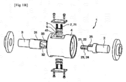
図1は、回転運動を伝達するための非戻りデバイス1を例示している。 Figure 1 illustrates a non-return device 1 for transmitting rotational motion.
このデバイス1は、非戻り機能、言い換えれば、インプットシャフトのアウトプットシャフトからの回転の伝達を妨げる機能を実装することによって、2本のシャフトの間で回転を伝達することを意図されている。 This device 1 is intended to transmit rotation between two shafts by implementing a non-return function, in other words a function that prevents the input shaft from transmitting rotation from the output shaft.
この非戻りデバイス1は、同軸上に配置構成されている、インプットシャフト2およびアウトプットシャフト3と、シャフト2、3の回転を案内するフレーム4と、を備える。
This non-return device 1 comprises an
シャフト2、3は、たとえば、既存のシステム(図示せず)に挿入され得、システムは、インプットシャフト2およびアウトプットシャフト3がそれぞれ接続される、非戻り機能を付加することが望まれている回転するように駆動されるシャフトと、従動シャフトと、を備える。
The
シャフトは、一方から他方へ軸回転運動を伝達する相互連携のための手段を備える。インプットシャフト2は、特に、アウトプットシャフト3を駆動することを意図されている。
The shafts are provided with means for mutual interaction to transmit axial rotational motion from one to the other. The
たとえば、インプットシャフトは、アウトプットシャフト3の雌端部32に係合する雄端部24を備える。
For example, the input shaft has a male end 24 that engages with the female end 32 of the
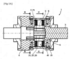
図2Aに例示されているように、フレーム4は、たとえば、滑り軸受または転がり軸受によって、シャフト2、3の回転を支持し、案内することができる。
As illustrated in FIG. 2A, the frame 4 can support and guide the rotation of the
係止要素5が、アウトプットシャフト3の横方向チャネル31内に挿入される。係止要素5は、係止位置と称される径方向の位置と、係止解除位置と称される径方向の位置と、の間で、前記チャネル31を通って径方向に並進することができる。
The
図2A、図2B、および図2Cに例示されている係止位置では、係止要素5は、チャネル31から突出する。したがって、これはフレーム4に当接することによってアウトプットシャフト3の回転を妨げる。
In the locked position illustrated in Figures 2A, 2B, and 2C, the
図3A、図3B、図3C、および図4に例示されている係止解除位置では、係止要素5は引っ込められ、フレームに当接せず、アウトプットシャフト3の軸回転を可能にする。
In the unlocked position illustrated in Figures 3A, 3B, 3C, and 4, the
たとえば、フレームは、係止解除位置において係止要素5が引っ込められる通路41を備える。係止位置では、通路41は、アウトプットシャフト3のチャネル31と一致し、次いで、係止要素5は、引っ込みかつアウトプットシャフト3の回転を可能にするように、前記通路41を通って径方向に並進することができる。
For example, the frame includes a
インプットシャフト2は、アウトプットシャフト3の駆動手段と、前記インプットシャフト2の回転運動を通じた径方向係止位置と係止解除位置との間の係止要素5の径方向切り替え手段21と、をさらに備える。対照的に、アウトプットシャフトは、係止要素5の切り替え手段を有していない。
The
インプットシャフト2を回転させると、アウトプットシャフト3の回転および係止要素5の係止解除位置への移動を実質的に同時に駆動する。
Rotating the
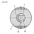
図2Bおよび図3Bを参照すると、インプットシャフト2は、たとえば、アウトプットシャフト3を回転させるためにアウトプットシャフト3の平坦部33に当接する段部25を備えている。インプットシャフト2の回転時に段部25が当接に至ることは、切り替え手段21を使用して係止要素5を係止解除位置に置くことと角度的に一致する。
2B and 3B, the
たとえば、係止要素5の切り替え手段21は、インプットシャフト2の回転時に係止要素5を径方向に移動させるように設計されている輪郭23を有するカム22を備える。
For example, the switching means 21 of the
有利には、カム22は、インプットシャフト2の雄端部24に設けられ、前記雄端部24はアウトプットシャフト3の雌端部32に係合される。カム22は、アウトプットシャフト内に係合し、それにより、係止要素5をチャネル31の内側からアウトプットシャフト3の外側の方へ径方向に押す。
Advantageously, the cam 22 is provided on the male end 24 of the
輪郭23は、たとえば、多角形である。多角形の頂点の数を増やすことで、デバイス1の係止解除位置の数を増加させることが可能である。
The
図2Cおよび図3Cに例示されている第1の実施形態において、輪郭23は、ひし形の形状を有し得る。次いで、係止位置(図2C)は、カム22が係止要素5を最小になるまで、その最小寸法だけ、すなわちひし形23の小高(small height)だけ径方向に押したときに到達し、係止解除位置(図3C)は、カム22が係止要素5を最大になるまで、その最大寸法だけ、すなわちひし形23の大高(large height)だけ径方向に押したときに到達する。
In the first embodiment illustrated in Figs. 2C and 3C, the
図4に例示されている第2の実施形態において、輪郭23は、六角形の切断面を有し得る。次いで、カム22が六角形23の頂点によって係止要素5を径方向に押したときに例示されているような係止解除位置に到達する。
In a second embodiment illustrated in FIG. 4, the
したがって、第1の実施形態では、アウトプットシャフト3を係止解除して回転させるために、インプットシャフト2を少なくとも1/4回転させることが必要であり、第2の実施形態では、20度の角度だけ回転させることが十分である。
Thus, in the first embodiment, it is necessary to rotate the
係止要素5の切り替え手段21は、カム22と係止要素5との間に挟装される係止解除キー6をさらに備えることができる。次いで、キー6は、アウトプットシャフト3のチャネル31を通る並進で接続される。これは、チャネル31から係止要素5を径方向に押し出す機能を有する。
The switching means 21 of the
係止位置(図2C)では、キー6は、チャネル31とアウトプットシャフト3との間に配置され、チャネル31から係止要素5を外すことはない。
In the locked position (FIG. 2C), the
係止解除位置(図3C)では、キーは、全体がチャネル31内に収納され、チャネル31から係止要素5を完全に外す。次いで、キー6は、回転が許されている、アウトプットシャフト3と一体で、シャフトの軸の周りに回転することができる。
In the unlocked position (FIG. 3C), the key is fully housed within the
キー6は、チャネル31に外接したまま、チャネル31から突出しないように、また係止解除位置でフレーム4に当接しないように、チャネル31に相補的な湾曲形状を有することができる。
The key 6 can have a curved shape complementary to the
それに加えて、デバイス1は、係止要素5の係止位置への弾性戻り手段7を含み、圧縮すると働き、係止要素5を、カム22に対抗してシャフト2、3の軸の方へ押す。
In addition, the device 1 includes elastic return means 7 for the
たとえば、係止位置への弾性戻り手段7は、フレーム4に接続されたバネ71を含む。 For example, the elastic return means 7 to the locking position includes a spring 71 connected to the frame 4.
したがって、係止解除位置(図3Cおよび図4)から、インプットシャフト2に対するアウトプットシャフト3の角度位置が、チャネル31が通路41と揃う位置に来た後、戻り手段7は、チャネル31内のキー6に対して係止要素5を押し付ける。次いで、係止位置は、チャネル31と通路41との間の係止要素5の突出位置決めによって係合され、これによりアウトプットシャフト3の回転を妨げることが可能である。
Thus, from the unlocked position (FIGS. 3C and 4), after the angular position of the
したがって、デバイスは、係止解除位置において、インプットシャフト2とアウトプットシャフト3との間の異種運動回転(heterokinetic rotation)の伝達、言い換えれば、インプットシャフト2の駆動手段ではなくアウトプットシャフトによって駆動される伝達により、チャネル31と通路41とを整列させ、したがって、戻り手段7を使用する係止位置への戻りを可能にする。
Thus, in the unlocked position, the device aligns the
そこで、インプットシャフト2の回転が係止手段5を係止解除し、回転運動を駆動手段25、33によって駆動されるアウトプットシャフト3に同軸的に伝達し、その一方でアウトプットシャフト3の回転がインプットシャフトを回転させず、デバイス1の係止位置への戻りをトリガーする、非戻りデバイスが作製される。
A no-return device is thus created in which rotation of the
1 非戻りデバイス
2 インプットシャフト
3 アウトプットシャフト
4 フレーム
5 係止要素
6 係止解除キー
7 弾性戻り手段
21 径方向切り替え手段
22 カム
23 輪郭
24 雄端部
25 段部
31 チャネル
32 雌端部
33 平坦部
41 通路
71 バネ
REFERENCE NUMERALS 1
Claims (6)
2本の同軸のインプットシャフト(2)およびアウトプットシャフト(3)と、
前記インプットシャフト(2)および前記アウトプットシャフト(3)の回転を案内するためのフレーム(4)と、
係止位置と径方向係止解除位置との間で前記アウトプットシャフト(3)のチャネル(31)を通って径方向に並進移動することができる係止要素(5)であって、前記係止位置では前記係止要素(5)は前記アウトプットシャフト(3)の回転を妨げるように前記チャネル(31)から突出し、前記径方向係止解除位置では前記係止要素(5)は前記アウトプットシャフト(3)の軸回転を可能にするように引っ込められ、前記インプットシャフト(2)は前記係止位置と前記径方向係止解除位置との間で前記係止要素を切り替えるための切り替え手段(21)を備える、係止要素(5)と、を具備し、
前記係止要素(5)の前記切り替え手段(21)は、前記インプットシャフト(2)の回転時に前記係止要素(5)を径方向に移動させるように適合されている輪郭(23)を有するカム(22)を備え、
前記インプットシャフト(2)は、前記アウトプットシャフト(3)を回転させるために前記アウトプットシャフト(3)の平坦部(33)に当接する段部(25)を備え、前記インプットシャフト(2)の回転時に前記段部(25)が当接に至ることは、前記カム(22)により前記係止要素(5)が前記径方向係止解除位置に置かれることと角度的に一致し、
前記係止要素(5)の前記切り替え手段(21)は、前記カム(22)と前記係止要素(5)との間に挟装される係止解除キー(6)を備え、前記係止解除キー(6)は前記アウトプットシャフト(3)の前記チャネル(31)を通して並進するように接続されることを特徴とする、回転運動を伝達するための非戻りデバイス(1)。 A non-return device (1) for transmitting a rotary motion, comprising:
Two coaxial input shafts (2) and output shafts (3);
a frame (4) for guiding the rotation of the input shaft (2) and the output shaft (3);
a locking element (5) radially translatable through a channel (31) of the output shaft (3) between a locked position and a radially unlocked position, in which the locking element (5) protrudes from the channel (31) to prevent rotation of the output shaft (3) and in which the locking element (5) is retracted to allow axial rotation of the output shaft (3), the input shaft (2) comprising a switching means (21) for switching the locking element between the locked position and the radially unlocked position,
the switching means (21) of the locking element (5) comprises a cam (22) having a profile (23) adapted to radially move the locking element (5) upon rotation of the input shaft (2),
the input shaft (2) comprises a step (25) which abuts against a flat portion (33) of the output shaft (3) to rotate the output shaft (3), and the abutment of the step (25) during rotation of the input shaft (2) is angularly coincident with the cam (22) placing the locking element (5) in the radial unlocked position ;
A non-return device (1) for transmitting a rotational motion, characterized in that the switching means (21) of the locking element (5) comprises an unlocking key (6) sandwiched between the cam (22) and the locking element (5), the unlocking key (6) being connected in translation through the channel (31) of the output shaft (3) .
Applications Claiming Priority (3)
| Application Number | Priority Date | Filing Date | Title |
|---|---|---|---|
| FR1909786A FR3100624B1 (en) | 2019-09-05 | 2019-09-05 | ROTATION TRANSMISSION ANTI-RETURN DEVICE |
| FR1909786 | 2019-09-05 | ||
| PCT/EP2020/074661 WO2021043934A1 (en) | 2019-09-05 | 2020-09-03 | Non-return rotation transmission device |
Publications (2)
| Publication Number | Publication Date |
|---|---|
| JP2022547122A JP2022547122A (en) | 2022-11-10 |
| JP7635209B2 true JP7635209B2 (en) | 2025-03-05 |
Family
ID=68211105
Family Applications (1)
| Application Number | Title | Priority Date | Filing Date |
|---|---|---|---|
| JP2022514976A Active JP7635209B2 (en) | 2019-09-05 | 2020-09-03 | Non-return rotation transmission device |
Country Status (6)
| Country | Link |
|---|---|
| US (1) | US11982326B2 (en) |
| EP (1) | EP4025799B1 (en) |
| JP (1) | JP7635209B2 (en) |
| ES (1) | ES2989731T3 (en) |
| FR (1) | FR3100624B1 (en) |
| WO (1) | WO2021043934A1 (en) |
Citations (1)
| Publication number | Priority date | Publication date | Assignee | Title |
|---|---|---|---|---|
| JP2018035871A (en) | 2016-08-31 | 2018-03-08 | Ntn株式会社 | Clutch unit |
Family Cites Families (5)
| Publication number | Priority date | Publication date | Assignee | Title |
|---|---|---|---|---|
| US1845667A (en) * | 1927-11-30 | 1932-02-16 | Charles A Johnson | Clutch |
| SE328723B (en) * | 1966-03-23 | 1970-09-21 | Naradi Narodni Podnik | |
| IT1227375B (en) * | 1988-11-22 | 1991-04-08 | Carraro Spa | DIFFERENTIAL MECHANISM FOR MOTOR VEHICLES. |
| US20150107953A1 (en) * | 2013-10-23 | 2015-04-23 | Jeffrey M. Lucas | Eccentric Lock One Way Clutch |
| KR101611719B1 (en) * | 2014-08-28 | 2016-04-14 | 주식회사 포스코 | Transfer device and Cutter having the same |
-
2019
- 2019-09-05 FR FR1909786A patent/FR3100624B1/en active Active
-
2020
- 2020-09-03 JP JP2022514976A patent/JP7635209B2/en active Active
- 2020-09-03 US US17/640,064 patent/US11982326B2/en active Active
- 2020-09-03 EP EP20764673.8A patent/EP4025799B1/en active Active
- 2020-09-03 ES ES20764673T patent/ES2989731T3/en active Active
- 2020-09-03 WO PCT/EP2020/074661 patent/WO2021043934A1/en not_active Ceased
Patent Citations (1)
| Publication number | Priority date | Publication date | Assignee | Title |
|---|---|---|---|---|
| JP2018035871A (en) | 2016-08-31 | 2018-03-08 | Ntn株式会社 | Clutch unit |
Also Published As
| Publication number | Publication date |
|---|---|
| US11982326B2 (en) | 2024-05-14 |
| FR3100624B1 (en) | 2021-10-08 |
| EP4025799B1 (en) | 2024-08-14 |
| FR3100624A1 (en) | 2021-03-12 |
| WO2021043934A1 (en) | 2021-03-11 |
| US20220341473A1 (en) | 2022-10-27 |
| JP2022547122A (en) | 2022-11-10 |
| EP4025799A1 (en) | 2022-07-13 |
| ES2989731T3 (en) | 2024-11-27 |
Similar Documents
| Publication | Publication Date | Title |
|---|---|---|
| US8844389B2 (en) | Automatically locking linear actuator | |
| JP6006490B2 (en) | Linear actuator and operation method thereof | |
| CN106996221B (en) | Redundant actuation locking device | |
| KR102623711B1 (en) | Snake-like robot | |
| CN104141419A (en) | Electromechanical cylinder lock with key override | |
| US20140312724A1 (en) | Electric push bar assembly | |
| CN108026987B (en) | Automatic clutch device | |
| CN110192046A (en) | Actuator with passive locking | |
| EP1532332A2 (en) | Electronic deadbolt lock arrangement | |
| EP2975202A1 (en) | Spring bolt arrangement | |
| CN213575255U (en) | Reverse locking device | |
| EP4635646A1 (en) | Pipe expander | |
| US3515251A (en) | Torque release and shutoff device for rotary tools | |
| EP4399424B1 (en) | Gear shift actuator | |
| US10267294B2 (en) | Spring return device | |
| CA2620557C (en) | Actuator device | |
| JP2022547122A (en) | Non-return rotary transmission device | |
| CN221715488U (en) | Pipe expander | |
| KR20230090312A (en) | Clutch for door lock | |
| US9903425B2 (en) | Positive mechanical rotary lock | |
| CN216317818U (en) | Saw blade mounting assembly for medical reciprocating saw and medical reciprocating saw | |
| US3315532A (en) | Cylinder extension coupling device | |
| KR101249937B1 (en) | Door lock having panic function | |
| CN113048171B (en) | Bidirectional self-locking transmission device | |
| CN214367574U (en) | A new type of two-way self-locking transmission device |
Legal Events
| Date | Code | Title | Description |
|---|---|---|---|
| A621 | Written request for application examination |
Free format text: JAPANESE INTERMEDIATE CODE: A621 Effective date: 20230809 |
|
| A977 | Report on retrieval |
Free format text: JAPANESE INTERMEDIATE CODE: A971007 Effective date: 20240613 |
|
| A131 | Notification of reasons for refusal |
Free format text: JAPANESE INTERMEDIATE CODE: A131 Effective date: 20240617 |
|
| A521 | Request for written amendment filed |
Free format text: JAPANESE INTERMEDIATE CODE: A523 Effective date: 20240729 |
|
| A02 | Decision of refusal |
Free format text: JAPANESE INTERMEDIATE CODE: A02 Effective date: 20240930 |
|
| A521 | Request for written amendment filed |
Free format text: JAPANESE INTERMEDIATE CODE: A523 Effective date: 20241107 |
|
| A911 | Transfer to examiner for re-examination before appeal (zenchi) |
Free format text: JAPANESE INTERMEDIATE CODE: A911 Effective date: 20241227 |
|
| TRDD | Decision of grant or rejection written | ||
| A01 | Written decision to grant a patent or to grant a registration (utility model) |
Free format text: JAPANESE INTERMEDIATE CODE: A01 Effective date: 20250121 |
|
| A61 | First payment of annual fees (during grant procedure) |
Free format text: JAPANESE INTERMEDIATE CODE: A61 Effective date: 20250212 |
|
| R150 | Certificate of patent or registration of utility model |
Ref document number: 7635209 Country of ref document: JP Free format text: JAPANESE INTERMEDIATE CODE: R150 |