JP7635249B2 - Latent Audio Tracking - Google Patents
Latent Audio Tracking Download PDFInfo
- Publication number
- JP7635249B2 JP7635249B2 JP2022548902A JP2022548902A JP7635249B2 JP 7635249 B2 JP7635249 B2 JP 7635249B2 JP 2022548902 A JP2022548902 A JP 2022548902A JP 2022548902 A JP2022548902 A JP 2022548902A JP 7635249 B2 JP7635249 B2 JP 7635249B2
- Authority
- JP
- Japan
- Prior art keywords
- origin
- determining
- user
- audio signal
- head
- Prior art date
- Legal status (The legal status is an assumption and is not a legal conclusion. Google has not performed a legal analysis and makes no representation as to the accuracy of the status listed.)
- Active
Links
Images





Classifications
-
- G—PHYSICS
- G06—COMPUTING OR CALCULATING; COUNTING
- G06F—ELECTRIC DIGITAL DATA PROCESSING
- G06F3/00—Input arrangements for transferring data to be processed into a form capable of being handled by the computer; Output arrangements for transferring data from processing unit to output unit, e.g. interface arrangements
- G06F3/01—Input arrangements or combined input and output arrangements for interaction between user and computer
- G06F3/011—Arrangements for interaction with the human body, e.g. for user immersion in virtual reality
-
- H—ELECTRICITY
- H04—ELECTRIC COMMUNICATION TECHNIQUE
- H04S—STEREOPHONIC SYSTEMS
- H04S7/00—Indicating arrangements; Control arrangements, e.g. balance control
- H04S7/30—Control circuits for electronic adaptation of the sound field
- H04S7/302—Electronic adaptation of stereophonic sound system to listener position or orientation
- H04S7/303—Tracking of listener position or orientation
- H04S7/304—For headphones
-
- H—ELECTRICITY
- H04—ELECTRIC COMMUNICATION TECHNIQUE
- H04S—STEREOPHONIC SYSTEMS
- H04S2400/00—Details of stereophonic systems covered by H04S but not provided for in its groups
- H04S2400/01—Multi-channel, i.e. more than two input channels, sound reproduction with two speakers wherein the multi-channel information is substantially preserved
-
- H—ELECTRICITY
- H04—ELECTRIC COMMUNICATION TECHNIQUE
- H04S—STEREOPHONIC SYSTEMS
- H04S2400/00—Details of stereophonic systems covered by H04S but not provided for in its groups
- H04S2400/11—Positioning of individual sound objects, e.g. moving airplane, within a sound field
Landscapes
- Engineering & Computer Science (AREA)
- Physics & Mathematics (AREA)
- General Engineering & Computer Science (AREA)
- Theoretical Computer Science (AREA)
- Acoustics & Sound (AREA)
- Signal Processing (AREA)
- Human Computer Interaction (AREA)
- General Physics & Mathematics (AREA)
- User Interface Of Digital Computer (AREA)
- Processing Or Creating Images (AREA)
- Stereophonic System (AREA)
Description
(関連出願の相互参照)
本願は、その内容が、参照することによってその全体として本明細書に組み込まれる、2020年2月14日に出願された、米国仮出願第62/976,986号の利益を請求する。
CROSS-REFERENCE TO RELATED APPLICATIONS
This application claims the benefit of U.S. Provisional Application No. 62/976,986, filed February 14, 2020, the contents of which are incorporated herein by reference in their entirety.
本開示は、一般に、オーディオをユーザに提示するためのシステムおよび方法に関し、特に、複合現実環境内でオーディオをユーザに提示するためのシステムおよび方法に関する。 The present disclosure relates generally to systems and methods for presenting audio to a user, and more particularly to systems and methods for presenting audio to a user in a mixed reality environment.
仮想環境は、コンピューティング環境において普遍的であって、ビデオゲーム(仮想環境が、ゲーム世界を表し得る)、マップ(仮想環境が、ナビゲートされるべき地形を表し得る)、シミュレーション(仮想環境が、実環境をシミュレートし得る)、デジタルストーリーテリング(仮想キャラクタが、仮想環境内で相互に相互作用し得る)、および多くの他の用途において使用を見出している。現代のコンピュータユーザは、概して、快適に仮想環境を知覚し、それと相互作用する。しかしながら、仮想環境を伴うユーザの体験は、仮想環境を提示するための技術によって限定され得る。例えば、従来のディスプレイ(例えば、2Dディスプレイ画面)およびオーディオシステム(例えば、固定スピーカ)は、人を引き付け、現実的で、かつ没入型の体験を作成するように、仮想環境を実現することが不可能であり得る。 Virtual environments are ubiquitous in computing environments, finding use in video games (where a virtual environment may represent a game world), maps (where a virtual environment may represent a terrain to be navigated), simulations (where a virtual environment may simulate a real environment), digital storytelling (where virtual characters may interact with one another within a virtual environment), and many other applications. Modern computer users are generally comfortable perceiving and interacting with virtual environments. However, a user's experience with a virtual environment may be limited by the technology for presenting the virtual environment. For example, conventional displays (e.g., 2D display screens) and audio systems (e.g., fixed speakers) may be unable to realize a virtual environment in a way that creates a compelling, realistic, and immersive experience.
仮想現実(「VR」)、拡張現実(「AR」)、複合現実(「MR」)、および関連技術(集合的に、「XR」)は、XRシステムのユーザに、コンピュータシステム内のデータによって表される仮想環境に対応する、感覚情報を提示する能力を共有する。そのようなシステムは、仮想視覚的およびオーディオキューと実光景および音を組み合わせることによって、一意に増大した没入感および現実性をもたらすことができる。故に、音が自然に生じているように感じられように、かつユーザの実環境内の音のユーザの予期と一貫して、デジタル音をXRシステムのユーザに提示することが望ましくあり得る。概して、ユーザは、仮想音が、その中で彼らに聞こえる、実環境の音響性質を帯びるであろうことを予期する。例えば、大コンサートホール内のXRシステムのユーザは、XRシステムの仮想音が、大洞窟のような音波品質を有することを予期し、逆に言えば、狭いアパート内のユーザは、音が、より減衰され、近く、かつ即座であることを予期するであろう。仮想音と実および/または仮想環境の音響性質を合致させることに加え、現実性はさらに、仮想音を空間化することによって向上される。例えば、仮想オブジェクトが、視覚的に、背後からユーザを越えて飛行し得、ユーザは、対応する仮想音がユーザに対する仮想オブジェクトの空間移動を同様に反映させることを予期し得る。 Virtual reality ("VR"), augmented reality ("AR"), mixed reality ("MR"), and related technologies (collectively, "XR") share the ability to present to a user of an XR system sensory information corresponding to a virtual environment represented by data in a computer system. Such systems can provide a uniquely increased sense of immersion and realism by combining virtual visual and audio cues with real sights and sounds. It may therefore be desirable to present digital sounds to a user of an XR system so that the sounds seem to occur naturally and are consistent with the user's expectations of sounds in the user's real environment. Generally, users expect that virtual sounds will take on the acoustic properties of the real environment in which they hear them. For example, a user of an XR system in a large concert hall would expect the virtual sounds of the XR system to have a cavernous sonic quality, and conversely, a user in a small apartment would expect the sounds to be more attenuated, close, and immediate. In addition to matching the acoustic properties of the virtual sounds with the real and/or virtual environment, realism is further enhanced by spatializing the virtual sounds. For example, a virtual object may visually fly over the user from behind, and the user may expect corresponding virtual sounds to similarly reflect the spatial movement of the virtual object relative to the user.
既存の技術は、多くの場合、ユーザの周囲を考慮せず、また仮想オブジェクトの空間移動に対応せず、ユーザ体験を損なわせ得る、不真正性の感覚につながる、仮想オーディオを提示すること等によって、これらの予期を欠いている。XRシステムのユーザの観察は、ユーザが、仮想コンテンツと実環境との間の視覚的不整合(例えば、照明における不一致)には比較的に寛容であり得るが、ユーザが、聴覚的不整合により敏感であり得ることを示す。我々の生活全体を通して持続的に精緻化される、我々の独自の聴覚的体験は、我々に、我々の物理的環境が我々が聞こえる音にどのように影響を及ぼすかを敏感に認知させ得、我々は、それらの予期と一致しない、音に非常に敏感であり得る。XRシステムでは、そのような不一致は、不快であり得、没入型かつ人を引き付ける体験を仕掛的な模倣したものに変えさせ得る。極端な実施例では、聴覚的不一致は、内耳が聴覚的刺激とその対応する視覚的キューを調和させることが不可能であるため、乗り物酔いおよび他の悪影響を及ぼし得る。 Existing technologies often miss these expectations, such as by presenting virtual audio that does not take into account the user's surroundings and does not accommodate the spatial movement of virtual objects, leading to a sense of inauthenticity that can detract from the user experience. Observations of users of XR systems indicate that while users can be relatively tolerant of visual inconsistencies between virtual content and the real environment (e.g., inconsistencies in lighting), they can be more sensitive to auditory inconsistencies. Our unique auditory experiences, which are continually refined throughout our lives, can make us acutely aware of how our physical environment affects the sounds we hear, and we can be highly sensitive to sounds that do not match those expectations. In XR systems, such inconsistencies can be unpleasant, turning an immersive and engaging experience into a gimmicky imitation. In extreme examples, auditory inconsistencies can cause motion sickness and other adverse effects due to the inability of the inner ear to reconcile an auditory stimulus with its corresponding visual cue.
我々のオーディオ感知に対する我々の感度のため、没入型のオーディオ体験は、没入型の視覚的体験より重要ではないにしても、それと等しく重要であり得る。XRシステムに利用可能な種々の感知および演算能力のため、XRシステムは、音を1つまたはそれを上回るチャネルに分裂させることによって、音を空間化し得る、従来的オーディオシステムよりはるかに没入型のオーディオ体験をもたらすように位置付けられ得る。例えば、ステレオヘッドホンは、左チャネルおよび右チャネルを使用して、オーディオをユーザに提示し、異なる方向から生じる音の出現を与え得る。いくつかのステレオヘッドホンは、(5.1チャネルのような)付加的チャネルをシミュレートし、オーディオ空間化をさらに向上させ得る。しかしながら、従来的システムは、空間化音位置がユーザに対して静的であるという事実に悩まされ得る。例えば、ユーザの左耳から5フィートの場所で生じるようにユーザに提示され得る、ギター音は、ユーザがその頭部を回転させるにつれて、ユーザに対して動的に変化し得ない。そのような静的挙動は、「実」環境内のオーディオ挙動を反映させ得ない。ライブオーケストラを鑑賞している人物は、例えば、小頭部移動に基づいて、そのオーディオ体験に若干の変化を被り得る。これらの小音響挙動は、累積し、没入型のオーディオ体験に追加され得る。したがって、XRシステムがユーザのオーディオ体験を向上させるためのオーディオシステムおよび方法を開発することが望ましい。 Due to our sensitivity to audio perception, an immersive audio experience may be equally, if not more important than an immersive visual experience. Due to the different sensing and computing power available to XR systems, XR systems may be positioned to provide a much more immersive audio experience than traditional audio systems, which may spatialize sound by splitting it into one or more channels. For example, stereo headphones may present audio to the user using left and right channels, giving the appearance of sounds originating from different directions. Some stereo headphones may simulate additional channels (such as 5.1 channels), further enhancing audio spatialization. However, traditional systems may suffer from the fact that spatialized sound locations are static relative to the user. For example, a guitar sound that may be presented to the user as originating 5 feet from the user's left ear may not dynamically change relative to the user as the user rotates his or her head. Such static behavior may not reflect the audio behavior in a "real" environment. A person listening to a live orchestra may experience slight changes in their audio experience based on, for example, small head movements. These small acoustic behaviors may accumulate and add to the immersive audio experience. It is therefore desirable to develop audio systems and methods for XR systems to enhance the audio experience of the user.
ユーザの物理的環境の特性を考慮することによって、本明細書に説明されるシステムおよび方法は、ユーザによって聞こえるであろうものを、仮想音がその環境内で自然に生成される実音であるかのように、シミュレートすることができる。音が実世界内で挙動する方法に忠実な様式において、仮想音を提示することによって、ユーザは、複合現実環境とのつながりの増大した感覚を体験し得る。同様に、ユーザの移動および環境に応答する、場所を意識した仮想コンテンツを提示することによって、コンテンツは、より主観的で、双方向で、かつ現実的となり、例えば、点Aにおけるユーザの体験は、点Bにおけるその体験と全体的に異なり得る。本向上された現実性および相互作用は、空間的に意識したオーディオを使用して、新規形態のゲームプレー、ソーシャル特徴、または双方向挙動を有効にするもの等、複合現実の新しい用途のための基盤を提供することができる。 By taking into account the characteristics of the user's physical environment, the systems and methods described herein can simulate what the user would hear as if the virtual sounds were real sounds naturally generated in that environment. By presenting virtual sounds in a manner that is faithful to the way sounds behave in the real world, the user may experience an increased sense of connection with the mixed reality environment. Similarly, by presenting location-aware virtual content that responds to the user's movements and environment, the content becomes more subjective, interactive, and realistic; for example, a user's experience at point A may be entirely different from his or her experience at point B. This enhanced realism and interaction can provide the foundation for new applications of mixed reality, such as those that use spatially aware audio to enable novel forms of gameplay, social features, or interactive behaviors.
本開示の実施例は、複合現実オーディオを提示するためのシステムおよび方法を説明する。本開示の実施例によると、オーディオが、ウェアラブル頭部デバイスのユーザに提示される。第1の時間におけるユーザの頭部の第1の位置が、ウェアラブル頭部デバイスの1つまたはそれを上回るセンサに基づいて決定される。第1の時間より後の第2の時間におけるユーザの頭部の第2の位置が、1つまたはそれを上回るセンサに基づいて決定される。オーディオ信号が、第1の位置と第2の位置との間の差異に基づいて決定される。オーディオ信号は、ウェアラブル頭部デバイスのスピーカを介して、ユーザに提示される。オーディオ信号を決定することは、仮想環境内のオーディオ信号の起点を決定することを含む。オーディオ信号をユーザに提示することは、決定された起点から生じるかのように、オーディオ信号を提示することを含む。オーディオ信号の起点を決定することは、オフセットをユーザの頭部の位置に適用することを含む。
本発明は、例えば、以下を提供する。
(項目1)
システムであって、
スピーカおよび1つまたはそれを上回るセンサを有するウェアラブル頭部デバイスと、
1つまたはそれを上回るプロセッサであって、
前記1つまたはそれを上回るセンサに基づいて、第1の時間におけるユーザの頭部の第1の位置を決定することと、
前記1つまたはそれを上回るセンサに基づいて、前記第1の時間より後の第2の時間における前記ユーザの頭部の第2の位置を決定することと、
前記第1の位置と前記第2の位置との間の差異に基づいて、オーディオ信号を決定することと、
前記スピーカを介して、前記オーディオ信号を前記ユーザに提示することと
を含む方法を実施するように構成される、1つまたはそれを上回るプロセッサと
を備え、
前記オーディオ信号を決定することは、仮想環境内の前記オーディオ信号の起点を決定することを含み、
前記オーディオ信号を前記ユーザに提示することは、前記決定された起点から生じるかのように、前記オーディオ信号を提示することを含み、
前記オーディオ信号の起点を決定することは、オフセットを前記ユーザの頭部の位置に適用することを含む、システム。
(項目2)
前記オーディオ信号の起点を決定することはさらに、前記ユーザの頭部の位置の変化率に基づいて、前記オーディオ信号の起点を決定することを含む、項目1に記載のシステム。
(項目3)
前記オーディオ信号の起点を決定することはさらに、
前記変化率が閾値を超えることの決定に従って、前記起点が第1の起点を備えることを決定することと、
前記変化率が前記閾値を超えないことの決定に従って、前記起点が前記第1の起点と異なる第2の起点を備えることを決定することと
を含む、項目2に記載のシステム。
(項目4)
前記オーディオ信号の起点を決定することはさらに、
前記オフセットの大きさが閾値を下回ることの決定に従って、前記起点が第1の起点を備えることを決定することと、
前記オフセットの大きさが前記閾値を下回らないことの決定に従って、前記起点が前記第1の起点と異なる第2の起点を備えることを決定することと
を含む、項目1に記載のシステム。
(項目5)
前記オーディオ信号を決定することはさらに、前記仮想環境内の速度を決定することを含み、
前記オーディオ信号を前記ユーザに提示することはさらに、前記起点が前記決定された速度で運動するかのように、前記オーディオ信号を提示することを含む、
項目1に記載のシステム。
(項目6)
前記速度を決定することは、前記ユーザの頭部の第1の位置と前記ユーザの頭部の第2の位置との間の差異に基づいて、前記速度を決定することを含む、項目5に記載のシステム。
(項目7)
前記オフセットは、前記ユーザの頭部の第1の位置に基づいて決定される、項目1に記載のシステム。
(項目8)
オーディオをウェアラブル頭部デバイスのユーザに提示する方法であって、
前記ウェアラブル頭部デバイスの1つまたはそれを上回るセンサに基づいて、第1の時間における前記ユーザの頭部の第1の位置を決定することと、
前記1つまたはそれを上回るセンサに基づいて、前記第1の時間より後の第2の時間における前記ユーザの頭部の第2の位置を決定することと、
前記第1の位置と前記第2の位置との間の差異に基づいて、オーディオ信号を決定することと、
前記ウェアラブル頭部デバイスのスピーカを介して、前記オーディオ信号を前記ユーザに提示することと
を含み、
前記オーディオ信号を決定することは、仮想環境内の前記オーディオ信号の起点を決定することを含み、
前記オーディオ信号を前記ユーザに提示することは、前記決定された起点から生じるかのように、前記オーディオ信号を提示することを含み、
前記オーディオ信号の起点を決定することは、オフセットを前記ユーザの頭部の位置に適用することを含む、方法。
(項目9)
前記オーディオ信号の起点を決定することはさらに、前記ユーザの頭部の位置の変化率に基づいて、前記オーディオ信号の起点を決定することを含む、項目8に記載の方法。
(項目10)
前記オーディオ信号の起点を決定することはさらに、
前記変化率が閾値を超えることの決定に従って、前記起点が第1の起点を備えることを決定することと、
前記変化率が前記閾値を超えないことの決定に従って、前記起点が前記第1の起点と異なる第2の起点を備えることを決定することと
を含む、項目9に記載の方法。
(項目11)
前記オーディオ信号の起点を決定することはさらに、
前記オフセットの大きさが閾値を下回ることの決定に従って、前記起点が第1の起点を備えることを決定することと、
前記オフセットの大きさが前記閾値を下回らないことの決定に従って、前記起点が前記第1の起点と異なる第2の起点を備えることを決定することと
を含む、項目8に記載の方法。
(項目12)
前記オーディオ信号を決定することはさらに、前記仮想環境内の速度を決定することを含み、
前記オーディオ信号を前記ユーザに提示することはさらに、前記起点が前記決定された速度で運動するかのように、前記オーディオ信号を提示することを含む、
項目8に記載の方法。
(項目13)
前記速度を決定することは、前記ユーザの頭部の第1の位置と前記ユーザの頭部の第2の位置との間の差異に基づいて、前記速度を決定することを含む、項目12に記載の方法。
(項目14)
前記オフセットは、前記ユーザの頭部の第1の位置に基づいて決定される、項目8に記載の方法。
(項目15)
非一過性コンピュータ可読媒体であって、前記非一過性コンピュータ可読媒体は、命令を記憶しており、前記命令は、1つまたはそれを上回るプロセッサによって実行されると、前記1つまたはそれを上回るプロセッサに、オーディオをウェアラブル頭部デバイスのユーザに提示する方法を実施させ、前記方法は、
前記ウェアラブル頭部デバイスの1つまたはそれを上回るセンサに基づいて、第1の時間における前記ユーザの頭部の第1の位置を決定することと、
前記1つまたはそれを上回るセンサに基づいて、前記第1の時間より後の第2の時間における前記ユーザの頭部の第2の位置を決定することと、
前記第1の位置と前記第2の位置との間の差異に基づいて、オーディオ信号を決定することと、
前記ウェアラブル頭部デバイスのスピーカを介して、前記オーディオ信号を前記ユーザに提示することと
を含み、
前記オーディオ信号を決定することは、仮想環境内の前記オーディオ信号の起点を決定することを含み、
前記オーディオ信号を前記ユーザに提示することは、前記決定された起点から生じるかのように、前記オーディオ信号を提示することを含み、
前記オーディオ信号の起点を決定することは、オフセットを前記ユーザの頭部の位置に適用することを含む、
非一過性コンピュータ可読媒体。
(項目16)
前記オーディオ信号の起点を決定することはさらに、前記ユーザの頭部の位置の変化率に基づいて、前記オーディオ信号の起点を決定することを含む、項目15に記載の非一過性コンピュータ可読媒体。
(項目17)
前記オーディオ信号の起点を決定することはさらに、
前記変化率が閾値を超えることの決定に従って、前記起点が第1の起点を備えることを決定することと、
前記変化率が前記閾値を超えないことの決定に従って、前記起点が前記第1の起点と異なる第2の起点を備えることを決定することと
を含む、項目16に記載の非一過性コンピュータ可読媒体。
(項目18)
前記オーディオ信号の起点を決定することはさらに、
前記オフセットの大きさが閾値を下回ることの決定に従って、前記起点が第1の起点を備えることを決定することと、
前記オフセットの大きさが前記閾値を下回らないことの決定に従って、前記起点が前記第1の起点と異なる第2の起点を備えることを決定することと
を含む、項目15に記載の非一過性コンピュータ可読媒体。
(項目19)
前記オーディオ信号を決定することはさらに、前記仮想環境内の速度を決定することを含み、
前記オーディオ信号を前記ユーザに提示することはさらに、前記起点が前記決定された速度で運動するかのように、前記オーディオ信号を提示することを含む、
項目15に記載の非一過性コンピュータ可読媒体。
(項目20)
前記速度を決定することは、前記ユーザの頭部の第1の位置と前記ユーザの頭部の第2の位置との間の差異に基づいて、前記速度を決定することを含む、項目19に記載の非一過性コンピュータ可読媒体。
An embodiment of the present disclosure describes a system and method for presenting mixed reality audio. According to an embodiment of the present disclosure, audio is presented to a user of a wearable head device. A first position of the user's head at a first time is determined based on one or more sensors of the wearable head device. A second position of the user's head at a second time, later than the first time, is determined based on the one or more sensors. An audio signal is determined based on a difference between the first position and the second position. The audio signal is presented to the user via a speaker of the wearable head device. Determining the audio signal includes determining an origin of the audio signal within the virtual environment. Presenting the audio signal to the user includes presenting the audio signal as if originating from the determined origin. Determining the origin of the audio signal includes applying an offset to the position of the user's head.
The present invention provides, for example, the following:
(Item 1)
1. A system comprising:
a wearable head device having a speaker and one or more sensors;
One or more processors,
determining a first position of a user's head at a first time based on the one or more sensors;
determining a second position of the user's head at a second time, after the first time, based on the one or more sensors; and
determining an audio signal based on a difference between the first position and the second position;
presenting the audio signal to the user via the speaker;
one or more processors configured to perform a method including:
Equipped with
determining the audio signal includes determining an origin of the audio signal within a virtual environment;
presenting the audio signal to the user includes presenting the audio signal as if originating from the determined origin;
The system, wherein determining an origin of the audio signal includes applying an offset to a position of the user's head.
(Item 2)
2. The system of claim 1, wherein determining an origin of the audio signal further comprises determining an origin of the audio signal based on a rate of change of a position of the user's head.
(Item 3)
Determining an origin of the audio signal further comprises:
determining that the origin comprises a first origin in accordance with determining that the rate of change exceeds a threshold;
determining, in response to the determination that the rate of change does not exceed the threshold, that the origin comprises a second origin different from the first origin;
3. The system according to item 2, comprising:
(Item 4)
Determining an origin of the audio signal further comprises:
determining that the origin comprises a first origin in accordance with determining that the magnitude of the offset is below a threshold; and
determining, in response to determining that the magnitude of the offset is not less than the threshold, that the origin comprises a second origin different from the first origin;
2. The system according to claim 1, comprising:
(Item 5)
determining the audio signal further includes determining a velocity within the virtual environment;
presenting the audio signal to the user further includes presenting the audio signal as if the origin were moving at the determined velocity.
2. The system according to item 1.
(Item 6)
6. The system of claim 5, wherein determining the velocity includes determining the velocity based on a difference between a first position of the user's head and a second position of the user's head.
(Item 7)
2. The system of claim 1, wherein the offset is determined based on a first position of the user's head.
(Item 8)
1. A method for presenting audio to a user of a wearable head device, comprising:
determining a first position of the user's head at a first time based on one or more sensors of the wearable head device;
determining a second position of the user's head at a second time, after the first time, based on the one or more sensors; and
determining an audio signal based on a difference between the first position and the second position;
presenting the audio signal to the user via a speaker of the wearable head device;
Including,
determining the audio signal includes determining an origin of the audio signal within a virtual environment;
presenting the audio signal to the user includes presenting the audio signal as if originating from the determined origin;
A method, wherein determining an origin of the audio signal includes applying an offset to a position of the user's head.
(Item 9)
9. The method of claim 8, wherein determining an origin of the audio signal further comprises determining an origin of the audio signal based on a rate of change of a position of the user's head.
(Item 10)
Determining an origin of the audio signal further comprises:
determining that the origin comprises a first origin in accordance with determining that the rate of change exceeds a threshold;
determining, in response to the determination that the rate of change does not exceed the threshold, that the origin comprises a second origin different from the first origin;
10. The method of claim 9, comprising:
(Item 11)
Determining an origin of the audio signal further comprises:
determining that the origin comprises a first origin in accordance with determining that the magnitude of the offset is below a threshold; and
determining, in response to determining that the magnitude of the offset is not less than the threshold, that the origin comprises a second origin different from the first origin;
9. The method according to claim 8, comprising:
(Item 12)
determining the audio signal further includes determining a velocity within the virtual environment;
presenting the audio signal to the user further includes presenting the audio signal as if the origin were moving at the determined velocity.
The method according to item 8.
(Item 13)
13. The method of claim 12, wherein determining the velocity includes determining the velocity based on a difference between a first position of the user's head and a second position of the user's head.
(Item 14)
9. The method of claim 8, wherein the offset is determined based on a first position of the user's head.
(Item 15)
1. A non-transitory computer readable medium having instructions stored thereon that, when executed by one or more processors, cause the one or more processors to perform a method of presenting audio to a user of a wearable head device, the method comprising:
determining a first position of the user's head at a first time based on one or more sensors of the wearable head device;
determining a second position of the user's head at a second time, after the first time, based on the one or more sensors; and
determining an audio signal based on a difference between the first position and the second position;
presenting the audio signal to the user via a speaker of the wearable head device;
Including,
determining the audio signal includes determining an origin of the audio signal within a virtual environment;
presenting the audio signal to the user includes presenting the audio signal as if originating from the determined origin;
determining an origin of the audio signal includes applying an offset to a position of the user's head;
Non-transitory computer readable medium.
(Item 16)
20. The non-transitory computer-readable medium of claim 15, wherein determining an origin of the audio signal further comprises determining an origin of the audio signal based on a rate of change of a position of the user's head.
(Item 17)
Determining an origin of the audio signal further comprises:
determining that the origin comprises a first origin in accordance with determining that the rate of change exceeds a threshold;
determining, in response to the determination that the rate of change does not exceed the threshold, that the origin comprises a second origin different from the first origin;
20. The non-transitory computer-readable medium of claim 16, comprising:
(Item 18)
Determining an origin of the audio signal further comprises:
determining that the origin comprises a first origin in accordance with determining that the magnitude of the offset is below a threshold; and
determining, in response to determining that the magnitude of the offset is not less than the threshold, that the origin comprises a second origin different from the first origin;
Item 16. The non-transitory computer-readable medium of item 15, comprising:
(Item 19)
determining the audio signal further includes determining a velocity within the virtual environment;
presenting the audio signal to the user further includes presenting the audio signal as if the origin were moving at the determined velocity.
Item 16. The non-transitory computer-readable medium of item 15.
(Item 20)
20. The non-transitory computer-readable medium of claim 19, wherein determining the velocity includes determining the velocity based on a difference between a first position of the user's head and a second position of the user's head.
詳細な説明
実施例の以下の説明では、本明細書の一部を形成し、例証として、実践され得る具体的実施例が示される、付随の図面を参照する。他の実施例も、使用されることができ、構造変更が、開示される実施例の範囲から逸脱することなく、行われることができることを理解されたい。
DETAILED DESCRIPTION In the following description of the embodiments, reference is made to the accompanying drawings which form a part hereof, and in which is shown, by way of illustration, specific embodiments which may be practiced. It is to be understood that other embodiments may be used and structural changes may be made without departing from the scope of the disclosed embodiments.
複合現実環境 Mixed reality environment
全ての人々と同様に、複合現実システムのユーザは、実環境内に存在する、すなわち、「実世界」の3次元部分と、そのコンテンツの全てとが、ユーザによって知覚可能である。例えば、ユーザは、通常の人間の感覚、すなわち、視覚、聴覚、触覚、味覚、嗅覚を使用して、実環境を知覚し、実環境内で自身の身体を移動させることによって、実環境と相互作用する。実環境内の場所は、座標空間内の座標として説明されることができる。例えば、座標は、緯度、経度、および海抜に対する高度、基準点から3つの直交次元における距離、または他の好適な値を含むことができる。同様に、ベクトルは、座標空間内の方向および大きさを有する、量を説明することができる。 Like all people, users of a mixed reality system exist in a real environment, i.e., the three-dimensional portion of the "real world" and all of its content are perceivable by the user. For example, the user perceives the real environment using normal human senses, i.e., sight, hearing, touch, taste, and smell, and interacts with the real environment by moving his or her body within the real environment. Locations within the real environment can be described as coordinates in a coordinate space. For example, coordinates can include latitude, longitude, and altitude relative to sea level, distance in three orthogonal dimensions from a reference point, or other suitable values. Similarly, a vector can describe a quantity that has a direction and magnitude in a coordinate space.
コンピューティングデバイスは、例えば、デバイスと関連付けられるメモリ内に、仮想環境の表現を維持することができる。本明細書で使用されるように、仮想環境は、3次元空間の算出表現である。仮想環境は、任意のオブジェクトの表現、アクション、信号、パラメータ、座標、ベクトル、またはその空間と関連付けられる他の特性を含むことができる。いくつかの実施例では、コンピューティングデバイスの回路(例えば、プロセッサ)は、仮想環境の状態を維持および更新することができる。すなわち、プロセッサは、第1の時間t0において、仮想環境と関連付けられるデータおよび/またはユーザによって提供される入力に基づいて、第2の時間t1における仮想環境の状態を決定することができる。例えば、仮想環境内のオブジェクトが、時間t0において、第1の座標に位置し、あるプログラムされた物理的パラメータ(例えば、質量、摩擦係数)を有し、ユーザから受信された入力が、力がある方向ベクトルにおいてオブジェクトに印加されるべきであることを示す場合、プロセッサは、運動学の法則を適用し、基本力学を使用して、時間t1におけるオブジェクトの場所を決定することができる。プロセッサは、仮想環境について既知の任意の好適な情報および/または任意の好適な入力を使用して、時間t1における仮想環境の状態を決定することができる。仮想環境の状態を維持および更新する際、プロセッサは、仮想環境内の仮想オブジェクトの作成および削除に関連するソフトウェア、仮想環境内の仮想オブジェクトまたはキャラクタの挙動を定義するためのソフトウェア(例えば、スクリプト)、仮想環境内の信号(例えば、オーディオ信号)の挙動を定義するためのソフトウェア、仮想環境と関連付けられるパラメータを作成および更新するためのソフトウェア、仮想環境内のオーディオ信号を生成するためのソフトウェア、入力および出力をハンドリングするためのソフトウェア、ネットワーク動作を実装するためのソフトウェア、アセットデータ(例えば、仮想オブジェクトを経時的に移動させるためのアニメーションデータ)を適用するためのソフトウェア、または多くの他の可能性を含む、任意の好適なソフトウェアを実行することができる。 A computing device may maintain a representation of a virtual environment, for example, in a memory associated with the device. As used herein, a virtual environment is a computed representation of a three-dimensional space. A virtual environment may include representations of any objects, actions, signals, parameters, coordinates, vectors, or other properties associated with that space. In some examples, a circuit (e.g., a processor) of a computing device may maintain and update the state of the virtual environment. That is, the processor may determine the state of the virtual environment at a second time t1 based on data associated with the virtual environment and/or input provided by a user at a first time t0. For example, if an object in the virtual environment is located at a first coordinate at time t0 and has certain programmed physical parameters (e.g., mass, coefficient of friction), and input received from a user indicates that a force should be applied to the object in a certain directional vector, the processor may apply the laws of kinematics and use basic mechanics to determine the location of the object at time t1. The processor may use any suitable information known about the virtual environment and/or any suitable input to determine the state of the virtual environment at time t1. In maintaining and updating the state of the virtual environment, the processor may execute any suitable software, including software associated with creating and deleting virtual objects in the virtual environment, software (e.g., scripts) for defining behavior of virtual objects or characters in the virtual environment, software for defining behavior of signals (e.g., audio signals) in the virtual environment, software for creating and updating parameters associated with the virtual environment, software for generating audio signals in the virtual environment, software for handling inputs and outputs, software for implementing network operations, software for applying asset data (e.g., animation data for moving a virtual object over time), or many other possibilities.
ディスプレイまたはスピーカ等の出力デバイスは、仮想環境のいずれかまたは全ての側面をユーザに提示することができる。例えば、仮想環境は、ユーザに提示され得る、仮想オブジェクト(無生物オブジェクト、人々、動物、光等の表現を含み得る)を含んでもよい。プロセッサは、仮想環境のビュー(例えば、原点座標、視軸、および錐台を伴う、「カメラ」に対応する)を決定し、ディスプレイに、そのビューに対応する仮想環境の視認可能場面をレンダリングすることができる。任意の好適なレンダリング技術が、本目的のために使用されてもよい。いくつかの実施例では、視認可能場面は、仮想環境内のいくつかの仮想オブジェクトのみを含み、ある他の仮想オブジェクトを除外してもよい。同様に、仮想環境は、ユーザに1つまたはそれを上回るオーディオ信号として提示され得る、オーディオ側面を含んでもよい。例えば、仮想環境内の仮想オブジェクトは、オブジェクトの場所座標から生じる音を生成してもよい(例えば、仮想キャラクタが、発話する、または音効果を生じさせ得る)、または仮想環境は、特定の場所と関連付けられる場合とそうではない場合がある、音楽キューまたは周囲音と関連付けられてもよい。プロセッサは、「聴取者」座標に対応するオーディオ信号、例えば、仮想環境内の音の合成に対応し、聴取者座標において聴取者によって聞こえるであろうオーディオ信号をシミュレートするように混合および処理される、オーディオ信号を決定し、ユーザに、1つまたはそれを上回るスピーカを介して、オーディオ信号を提示することができる。 An output device, such as a display or speaker, can present any or all aspects of the virtual environment to the user. For example, the virtual environment may include virtual objects (which may include representations of inanimate objects, people, animals, lights, etc.) that may be presented to the user. The processor can determine a view of the virtual environment (e.g., corresponding to a "camera," with its origin coordinates, viewing axis, and frustum) and render on the display a viewable scene of the virtual environment that corresponds to that view. Any suitable rendering technique may be used for this purpose. In some examples, the viewable scene may include only some virtual objects in the virtual environment and exclude certain other virtual objects. Similarly, the virtual environment may include audio aspects that may be presented to the user as one or more audio signals. For example, a virtual object in the virtual environment may generate sounds that originate from the object's location coordinates (e.g., a virtual character may speak or create a sound effect), or the virtual environment may be associated with musical cues or ambient sounds that may or may not be associated with a particular location. The processor can determine audio signals corresponding to "listener" coordinates, e.g., audio signals corresponding to the synthesis of sounds in the virtual environment and that are mixed and processed to simulate the audio signals that would be heard by a listener at the listener coordinates, and present the audio signals to the user via one or more speakers.
仮想環境は、算出構造としてのみ存在するため、ユーザは、直接、通常の感覚を使用して、仮想環境を知覚することができない。代わりに、ユーザは、例えば、ディスプレイ、スピーカ、触覚的出力デバイス等によって、ユーザに提示されるように、間接的にのみ、仮想環境を知覚することができる。同様に、ユーザは、直接、仮想環境に触れる、それを操作する、または別様に、それと相互作用することができないが、入力データを、入力デバイスまたはセンサを介して、デバイスまたはセンサデータを使用して、仮想環境を更新し得る、プロセッサに提供することができる。例えば、カメラセンサは、ユーザが仮想環境のオブジェクトを移動させようとしていることを示す、光学データを提供することができ、プロセッサは、そのデータを使用して、仮想環境内において、適宜、オブジェクトを応答させることができる。 Because the virtual environment exists only as a computational structure, the user cannot directly perceive the virtual environment using ordinary senses. Instead, the user can only indirectly perceive the virtual environment as presented to the user, for example, by a display, a speaker, a tactile output device, etc. Similarly, the user cannot directly touch, manipulate, or otherwise interact with the virtual environment, but can provide input data via input devices or sensors to a processor, which can use the device or sensor data to update the virtual environment. For example, a camera sensor can provide optical data indicating that the user is attempting to move an object in the virtual environment, and the processor can use that data to cause the object to respond appropriately within the virtual environment.
複合現実システムは、ユーザに、例えば、透過型ディスプレイおよび/または1つまたはそれを上回るスピーカ(例えば、ウェアラブル頭部デバイスの中に組み込まれ得る)を使用して、実環境および仮想環境の側面を組み合わせる、複合現実環境(「MRE」)を提示することができる。いくつかの実施形態では、1つまたはそれを上回るスピーカは、頭部搭載型ウェアラブルユニットの外部にあってもよい。本明細書で使用されるように、MREは、実環境および対応する仮想環境の同時表現である。いくつかの実施例では、対応する実および仮想環境は、単一座標空間を共有する。いくつかの実施例では、実座標空間および対応する仮想座標空間は、変換行列(または他の好適な表現)によって相互に関連する。故に、単一座標(いくつかの実施例では、変換行列とともに)は、実環境内の第1の場所と、また、仮想環境内の第2の対応する場所とを定義し得、その逆も同様である。 A mixed reality system can present a user with a mixed reality environment ("MRE") that combines aspects of real and virtual environments, for example, using a see-through display and/or one or more speakers (which may be incorporated, for example, into a wearable head device). In some embodiments, the one or more speakers may be external to the head-mounted wearable unit. As used herein, an MRE is a simultaneous representation of a real environment and a corresponding virtual environment. In some examples, the corresponding real and virtual environments share a single coordinate space. In some examples, the real coordinate space and the corresponding virtual coordinate space are related to each other by a transformation matrix (or other suitable representation). Thus, a single coordinate (in some examples, together with the transformation matrix) may define a first location in the real environment and a second corresponding location in the virtual environment, and vice versa.
MREでは、(例えば、MREと関連付けられる仮想環境内の)仮想オブジェクトは、(例えば、MREと関連付けられる実環境内の)実オブジェクトに対応し得る。例えば、MREの実環境が、実街灯柱(実オブジェクト)をある場所座標に含む場合、MREの仮想環境は、仮想街灯柱(仮想オブジェクト)を対応する場所座標に含んでもよい。本明細書で使用されるように、実オブジェクトは、その対応する仮想オブジェクトとともに組み合わせて、「複合現実オブジェクト」を構成する。仮想オブジェクトが対応する実オブジェクトに完璧に合致または整合することは、必要ではない。いくつかの実施例では、仮想オブジェクトは、対応する実オブジェクトの簡略化されたバージョンであることができる。例えば、実環境が、実街灯柱を含む場合、対応する仮想オブジェクトは、実街灯柱と概ね同一高さおよび半径の円筒形を含んでもよい(街灯柱が略円筒形形状であり得ることを反映する)。仮想オブジェクトをこのように簡略化することは、算出効率を可能にすることができ、そのような仮想オブジェクト上で実施されるための計算を簡略化することができる。さらに、MREのいくつかの実施例では、実環境内の全ての実オブジェクトが、対応する仮想オブジェクトと関連付けられなくてもよい。同様に、MREのいくつかの実施例では、仮想環境内の全ての仮想オブジェクトが、対応する実オブジェクトと関連付けられなくてもよい。すなわち、いくつかの仮想オブジェクトが、任意の実世界対応物を伴わずに、MREの仮想環境内にのみ存在し得る。 In an MRE, a virtual object (e.g., in a virtual environment associated with the MRE) may correspond to a real object (e.g., in a real environment associated with the MRE). For example, if the real environment of the MRE includes a real lamppost (a real object) at a location coordinate, the virtual environment of the MRE may include a virtual lamppost (a virtual object) at a corresponding location coordinate. As used herein, a real object combines with its corresponding virtual object to comprise a "mixed reality object." It is not necessary for a virtual object to perfectly match or match a corresponding real object. In some examples, a virtual object can be a simplified version of a corresponding real object. For example, if the real environment includes a real lamppost, the corresponding virtual object may include a cylinder of approximately the same height and radius as the real lamppost (reflecting that a lamppost may be approximately cylindrical in shape). Simplifying the virtual object in this way can enable computational efficiencies and simplify calculations to be performed on such virtual objects. Additionally, in some embodiments of the MRE, not all real objects in the real environment may be associated with corresponding virtual objects. Similarly, in some embodiments of the MRE, not all virtual objects in the virtual environment may be associated with corresponding real objects. That is, some virtual objects may exist only in the virtual environment of the MRE without any real-world counterparts.
いくつかの実施例では、仮想オブジェクトは、時として著しく、対応する実オブジェクトのものと異なる、特性を有してもよい。例えば、MRE内の実環境は、緑色の2本の枝が延びたサボテン、すなわち、とげだらけの無生物オブジェクトを含み得るが、MRE内の対応する仮想オブジェクトは、人間の顔特徴および無愛想な態度を伴う、緑色の2本の腕の仮想キャラクタの特性を有してもよい。本実施例では、仮想オブジェクトは、ある特性(色、腕の数)において、その対応する実オブジェクトに類似するが、他の特性(顔特徴、性格)において、実オブジェクトと異なる。このように、仮想オブジェクトは、創造的、抽象的、誇張された、または架空の様式において、実オブジェクトを表す、または挙動(例えば、人間の性格)をそうでなければ無生物である実オブジェクトに付与する潜在性を有する。いくつかの実施例では、仮想オブジェクトは、実世界対応物を伴わない、純粋に架空の創造物(例えば、おそらく、実環境内の虚空に対応する場所における、仮想環境内の仮想モンスタ)であってもよい。 In some embodiments, a virtual object may have characteristics that are different, sometimes significantly, from those of a corresponding real object. For example, a real environment in the MRE may contain a green, two-pronged cactus, a thorny inanimate object, while the corresponding virtual object in the MRE may have the characteristics of a green, two-armed virtual character with human facial features and a surly attitude. In this embodiment, the virtual object resembles its corresponding real object in some characteristics (color, number of arms) but differs from the real object in other characteristics (facial features, personality). In this way, virtual objects have the potential to represent real objects in creative, abstract, exaggerated, or fictional ways, or to impart behaviors (e.g., human personality) to otherwise inanimate real objects. In some embodiments, a virtual object may be a purely fictional creation with no real-world counterpart (e.g., a virtual monster in a virtual environment, perhaps in a location that corresponds to a void in the real environment).
ユーザに、実環境を不明瞭にしながら、仮想環境を提示する、VRシステムと比較して、MREを提示する、複合現実システムは、仮想環境が提示される間、実環境が知覚可能なままであるという利点をもたらす。故に、複合現実システムのユーザは、実環境と関連付けられる視覚的およびオーディオキューを使用して、対応する仮想環境を体験し、それと相互作用することが可能である。実施例として、VRシステムのユーザは、上記に述べられたように、ユーザが、直接、仮想環境を知覚する、またはそれと相互作用することができないため、仮想環境内に表示される仮想オブジェクトを知覚する、またはそれと相互作用することに苦戦し得るが、MRシステムのユーザは、その自身の実環境内の対応する実オブジェクトが見え、聞こえ、触れることによって、仮想オブジェクトと相互作用することが直感的および自然であると見出し得る。本レベルの相互作用は、ユーザの仮想環境との没入感、つながり、および関与の感覚を向上させ得る。同様に、実環境および仮想環境を同時に提示することによって、複合現実システムは、VRシステムと関連付けられる負の心理学的感覚(例えば、認知的不協和)および負の物理的感覚(例えば、乗り物酔い)を低減させることができる。複合現実システムはさらに、実世界の我々の体験を拡張または改変し得る用途に関する多くの可能性をもたらす。 Compared to a VR system that presents a virtual environment to a user while obscuring the real environment, a mixed reality system that presents an MRE offers the advantage that the real environment remains perceptible while the virtual environment is presented. Thus, a user of a mixed reality system can experience and interact with a corresponding virtual environment using visual and audio cues associated with the real environment. As an example, a user of a VR system may struggle to perceive or interact with a virtual object displayed in the virtual environment because the user cannot directly perceive or interact with the virtual environment, as described above, whereas a user of an MR system may find it intuitive and natural to interact with a virtual object by seeing, hearing, and touching the corresponding real object in his or her real environment. This level of interaction may enhance the user's sense of immersion, connection, and engagement with the virtual environment. Similarly, by presenting a real environment and a virtual environment simultaneously, a mixed reality system may reduce the negative psychological sensations (e.g., cognitive dissonance) and negative physical sensations (e.g., motion sickness) associated with a VR system. Mixed reality systems also offer many possibilities for applications that can augment or modify our experience of the real world.
図1Aは、ユーザ110が複合現実システム112を使用する、例示的実環境100を図示する。複合現実システム112は、ディスプレイ(例えば、透過型ディスプレイ)および1つまたはそれを上回るスピーカと、例えば、下記に説明されるような1つまたはそれを上回るセンサ(例えば、カメラ)とを含んでもよい。示される実環境100は、その中にユーザ110が立っている、長方形の部屋104Aと、実オブジェクト122A(ランプ)、124A(テーブル)、126A(ソファ)、および128A(絵画)とを含む。部屋104Aはさらに、場所座標106を含み、これは、実環境100の原点と見なされ得る。図1Aに示されるように、その原点を点106(世界座標)に伴う、環境/世界座標系108(x-軸108X、y-軸108Y、およびz-軸108Zを備える)は、実環境100のための座標空間を定義し得る。いくつかの実施形態では、環境/世界座標系108の原点106は、複合現実システム112の電源がオンにされた場所に対応し得る。いくつかの実施形態では、環境/世界座標系108の原点106は、動作の間、リセットされてもよい。いくつかの実施例では、ユーザ110は、実環境100内の実オブジェクトと見なされ得る。同様に、ユーザ110の身体部分(例えば、手、足)は、実環境100内の実オブジェクトと見なされ得る。いくつかの実施例では、その原点を点115(例えば、ユーザ/聴取者/頭部座標)に伴う、ユーザ/聴取者/頭部座標系114(x-軸114X、y-軸114Y、およびz-軸114Zを備える)は、その上に複合現実システム112が位置する、ユーザ/聴取者/頭部のための座標空間を定義し得る。ユーザ/聴取者/頭部座標系114の原点115は、複合現実システム112の1つまたはそれを上回るコンポーネントに対して定義されてもよい。例えば、ユーザ/聴取者/頭部座標系114の原点115は、複合現実システム112の初期較正等の間、複合現実システム112のディスプレイに対して定義されてもよい。行列(平行移動行列および四元数行列または他の回転行列を含み得る)または他の好適な表現が、ユーザ/聴取者/頭部座標系114空間と環境/世界座標系108空間との間の変換を特性評価することができる。いくつかの実施形態では、左耳座標116および右耳座標117が、ユーザ/聴取者/頭部座標系114の原点115に対して定義されてもよい。行列(平行移動行列および四元数行列または他の回転行列を含み得る)または他の好適な表現が、左耳座標116および右耳座標117とユーザ/聴取者/頭部座標系114空間との間の変換を特性評価することができる。ユーザ/聴取者/頭部座標系114は、ユーザの頭部または頭部搭載型デバイスに対する、例えば、環境/世界座標系108に対する場所の表現を簡略化することができる。同時位置特定およびマッピング(SLAM)、ビジュアルオドメトリ、または他の技法を使用して、ユーザ座標系114と環境座標系108との間の変換が、リアルタイムで決定および更新されることができる。
1A illustrates an exemplary
図1Bは、実環境100に対応する、例示的仮想環境130を図示する。示される仮想環境130は、実長方形部屋104Aに対応する仮想長方形部屋104Bと、実オブジェクト122Aに対応する仮想オブジェクト122Bと、実オブジェクト124Aに対応する仮想オブジェクト124Bと、実オブジェクト126Aに対応する仮想オブジェクト126Bとを含む。仮想オブジェクト122B、124B、126Bと関連付けられるメタデータは、対応する実オブジェクト122A、124A、126Aから導出される情報を含むことができる。仮想環境130は、加えて、仮想モンスタ132を含み、これは、実環境100内の任意の実オブジェクトに対応しない。実環境100内の実オブジェクト128Aは、仮想環境130内の任意の仮想オブジェクトに対応しない。その原点を点134(持続的座標)に伴う、持続的座標系133(x-軸133X、y-軸133Y、およびz-軸133Zを備える)は、仮想コンテンツのための座標空間を定義し得る。持続的座標系133の原点134は、実オブジェクト126A等の1つまたはそれを上回る実オブジェクトと相対的に/それに対して定義されてもよい。行列(平行移動行列および四元数行列または他の回転行列を含み得る)または他の好適な表現は、持続的座標系133空間と環境/世界座標系108空間との間の変換を特性評価することができる。いくつかの実施形態では、仮想オブジェクト122B、124B、126B、および132はそれぞれ、持続的座標系133の原点134に対するその自身の持続的座標点を有してもよい。いくつかの実施形態では、複数の持続的座標系が存在してもよく、仮想オブジェクト122B、124B、126B、および132はそれぞれ、1つまたはそれを上回る持続的座標系に対するその自身の持続的座標点を有してもよい。
1B illustrates an exemplary
図1Aおよび1Bに関して、環境/世界座標系108は、実環境100および仮想環境130の両方のための共有座標空間を定義する。示される実施例では、座標空間は、その原点を点106に有する。さらに、座標空間は、同一の3つの直交軸(108X、108Y、108Z)によって定義される。故に、実環境100内の第1の場所および仮想環境130内の第2の対応する場所は、同一座標空間に関して説明されることができる。これは、同一座標が両方の場所を識別するために使用され得るため、実および仮想環境内の対応する場所を識別および表示することを簡略化する。しかしながら、いくつかの実施例では、対応する実および仮想環境は、共有座標空間を使用する必要がない。例えば、いくつかの実施例では(図示せず)、行列(平行移動行列および四元数行列または他の回転行列を含み得る)または他の好適な表現は、実環境座標空間と仮想環境座標空間との間の変換を特性評価することができる。
1A and 1B, the environment/world coordinate
図1Cは、同時に、実環境100および仮想環境130の側面をユーザ110に複合現実システム112を介して提示する、例示的MRE150を図示する。示される実施例では、MRE150は、同時に、ユーザ110に、実環境100からの実オブジェクト122A、124A、126A、および128A(例えば、複合現実システム112のディスプレイの透過性部分を介して)と、仮想環境130からの仮想オブジェクト122B、124B、126B、および132(例えば、複合現実システム112のディスプレイのアクティブディスプレイ部分を介して)とを提示する。上記のように、原点106は、MRE150に対応する座標空間のための原点として作用し、座標系108は、座標空間のためのx-軸、y-軸、およびz-軸を定義する。
1C illustrates an
示される実施例では、複合現実オブジェクトは、座標空間108内の対応する場所を占有する、対応する対の実オブジェクトおよび仮想オブジェクト(すなわち、122A/122B、124A/124B、126A/126B)を含む。いくつかの実施例では、実オブジェクトおよび仮想オブジェクトは両方とも、同時に、ユーザ110に可視であってもよい。これは、例えば、仮想オブジェクトが対応する実オブジェクトのビューを拡張させるように設計される情報を提示する、インスタンスにおいて望ましくあり得る(仮想オブジェクトが古代の損傷された彫像の欠けた部分を提示する、博物館用途等)。いくつかの実施例では、仮想オブジェクト(122B、124B、および/または126B)は、対応する実オブジェクト(122A、124A、および/または126A)をオクルードするように、表示されてもよい(例えば、ピクセル化オクルージョンシャッタを使用する、アクティブピクセル化オクルージョンを介して)。これは、例えば、仮想オブジェクトが対応する実オブジェクトのための視覚的置換として作用する、インスタンスにおいて望ましくあり得る(無生物実オブジェクトが「生きている」キャラクタとなる、双方向ストーリーテリング用途等)。
In the example shown, the mixed reality objects include corresponding pairs of real and virtual objects (i.e., 122A/122B, 124A/124B, 126A/126B) that occupy corresponding locations in coordinate
いくつかの実施例では、実オブジェクト(例えば、122A、124A、126A)は、必ずしも、仮想オブジェクトを構成するとは限らない、仮想コンテンツまたはヘルパデータと関連付けられてもよい。仮想コンテンツまたはヘルパデータは、複合現実環境内の仮想オブジェクトの処理またはハンドリングを促進することができる。例えば、そのような仮想コンテンツは、対応する実オブジェクトの2次元表現、対応する実オブジェクトと関連付けられるカスタムアセットタイプ、または対応する実オブジェクトと関連付けられる統計的データを含み得る。本情報は、不必要な算出オーバーヘッドを被ることなく、実オブジェクトに関わる計算を可能にする、または促進することができる。 In some examples, real objects (e.g., 122A, 124A, 126A) may be associated with virtual content or helper data that does not necessarily constitute a virtual object. The virtual content or helper data may facilitate processing or handling of the virtual object within a mixed reality environment. For example, such virtual content may include a two-dimensional representation of the corresponding real object, a custom asset type associated with the corresponding real object, or statistical data associated with the corresponding real object. This information may enable or facilitate calculations involving the real object without incurring unnecessary computational overhead.
いくつかの実施例では、上記に説明される提示はまた、オーディオ側面を組み込んでもよい。例えば、MRE150では、仮想モンスタ132は、モンスタがMRE150の周囲を歩き回るにつれて生成される、足音効果等の1つまたはそれを上回るオーディオ信号と関連付けられ得る。下記にさらに説明されるように、複合現実システム112のプロセッサは、MRE150内の全てのそのような音の混合および処理された合成に対応するオーディオ信号を算出し、複合現実システム112内に含まれる1つまたはそれを上回るスピーカおよび/または1つまたはそれを上回る外部スピーカを介して、オーディオ信号をユーザ110に提示することができる。
In some embodiments, the presentation described above may also incorporate an audio aspect. For example, in the
例示的複合現実システム Example mixed reality system
例示的複合現実システム112は、ディスプレイ(接眼ディスプレイであり得る、左および右透過型ディスプレイと、ディスプレイからの光をユーザの眼に結合するための関連付けられるコンポーネントとを含み得る)と、左および右スピーカ(例えば、それぞれ、ユーザの左および右耳に隣接して位置付けられる)と、慣性測定ユニット(IMU)(例えば、頭部デバイスのつるのアームに搭載される)と、直交コイル電磁受信機(例えば、左つる部品に搭載される)と、ユーザから離れるように配向される、左および右カメラ(例えば、深度(飛行時間)カメラ)と、ユーザに向かって配向される、左および右眼カメラ(例えば、ユーザの眼移動を検出するため)とを備える、ウェアラブル頭部デバイス(例えば、ウェアラブル拡張現実または複合現実頭部デバイス)を含むことができる。しかしながら、複合現実システム112は、任意の好適なディスプレイ技術および任意の好適なセンサ(例えば、光学、赤外線、音響、LIDAR、EOG、GPS、磁気)を組み込むことができる。加えて、複合現実システム112は、ネットワーキング特徴(例えば、Wi-Fi能力)を組み込み、他の複合現実システムを含む、他のデバイスおよびシステムと通信してもよい。複合現実システム112はさらに、バッテリ(ユーザの腰部の周囲に装着されるように設計されるベルトパック等の補助ユニット内に搭載されてもよい)と、プロセッサと、メモリとを含んでもよい。複合現実システム112のウェアラブル頭部デバイスは、ユーザの環境に対するウェアラブル頭部デバイスの座標セットを出力するように構成される、IMUまたは他の好適なセンサ等の追跡コンポーネントを含んでもよい。いくつかの実施例では、追跡コンポーネントは、入力をプロセッサに提供し、同時位置特定およびマッピング(SLAM)および/またはビジュアルオドメトリアルゴリズムを実施してもよい。いくつかの実施例では、複合現実システム112はまた、ハンドヘルドコントローラ300、および/または下記にさらに説明されるように、ウェアラブルベルトパックであり得る、補助ユニット320を含んでもよい。
An exemplary
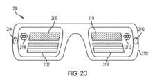
図2A-2Dは、MRE(MRE150に対応し得る)または他の仮想環境をユーザに提示するために使用され得る、例示的複合現実システム200(複合現実システム112に対応し得る)のコンポーネントを図示する。図2Aは、例示的複合現実システム200内に含まれるウェアラブル頭部デバイス2102の斜視図を図示する。図2Bは、ユーザの頭部2202上に装着されるウェアラブル頭部デバイス2102の上面図を図示する。図2Cは、ウェアラブル頭部デバイス2102の正面図を図示する。図2Dは、ウェアラブル頭部デバイス2102の例示的接眼レンズ2110の縁視図を図示する。図2A-2Cに示されるように、例示的ウェアラブル頭部デバイス2102は、例示的左接眼レンズ(例えば、左透明導波管セット接眼レンズ)2108と、例示的右接眼レンズ(例えば、右透明導波管セット接眼レンズ)2110とを含む。各接眼レンズ2108および2110は、それを通して実環境が可視となる、透過性要素と、実環境に重複するディスプレイ(例えば、画像毎に変調された光を介して)を提示するためのディスプレイ要素とを含むことができる。いくつかの実施例では、そのようなディスプレイ要素は、画像毎に変調された光の流動を制御するための表面回折光学要素を含むことができる。例えば、左接眼レンズ2108は、左内部結合格子セット2112と、左直交瞳拡張(OPE)格子セット2120と、左出射(出力)瞳拡張(EPE)格子セット2122とを含むことができる。同様に、右接眼レンズ2110は、右内部結合格子セット2118と、右OPE格子セット2114と、右EPE格子セット2116とを含むことができる。画像毎に変調された光は、内部結合格子2112および2118、OPE2114および2120、およびEPE2116および2122を介して、ユーザの眼に転送されることができる。各内部結合格子セット2112、2118は、光をその対応するOPE格子セット2120、2114に向かって偏向させるように構成されることができる。各OPE格子セット2120、2114は、光をその関連付けられるEPE2122、2116に向かって下方に漸次的に偏向させ、それによって、形成されている射出瞳を水平に延在させるように設計されることができる。各EPE2122、2116は、その対応するOPE格子セット2120、2114から受信された光の少なくとも一部を、接眼レンズ2108、2110の背後に定義される、ユーザアイボックス位置(図示せず)に外向きに漸次的に再指向し、アイボックスに形成される射出瞳を垂直に延在させるように構成されることができる。代替として、内部結合格子セット2112および2118、OPE格子セット2114および2120、およびEPE格子セット2116および2122の代わりに、接眼レンズ2108および2110は、ユーザの眼への画像毎に変調された光の結合を制御するための格子および/または屈折および反射性特徴の他の配列を含むことができる。
Figures 2A-2D illustrate components of an exemplary mixed reality system 200 (which may correspond to mixed reality system 112) that may be used to present an MRE (which may correspond to MRE 150) or other virtual environment to a user. Figure 2A illustrates a perspective view of a
いくつかの実施例では、ウェアラブル頭部デバイス2102は、左つるのアーム2130と、右つるのアーム2132とを含むことができ、左つるのアーム2130は、左スピーカ2134を含み、右つるのアーム2132は、右スピーカ2136を含む。直交コイル電磁受信機2138は、左こめかみ部品またはウェアラブル頭部ユニット2102内の別の好適な場所に位置することができる。慣性測定ユニット(IMU)2140は、右つるのアーム2132またはウェアラブル頭部デバイス2102内の別の好適な場所に位置することができる。ウェアラブル頭部デバイス2102はまた、左深度(例えば、飛行時間)カメラ2142と、右深度カメラ2144とを含むことができる。深度カメラ2142、2144は、好適には、ともにより広い視野を網羅するように、異なる方向に配向されることができる。
In some embodiments, the
図2A-2Dに示される実施例では、画像毎に変調された光の左源2124は、左内部結合格子セット2112を通して、左接眼レンズ2108の中に光学的に結合されることができ、画像毎に変調された光の右源2126は、右内部結合格子セット2118を通して、右接眼レンズ2110の中に光学的に結合されることができる。画像毎に変調された光の源2124、2126は、例えば、光ファイバスキャナ、デジタル光処理(DLP)チップまたはシリコン上液晶(LCoS)変調器等の電子光変調器を含む、プロジェクタ、または側面あたり1つまたはそれを上回るレンズを使用して、内部結合格子セット2112、2118の中に結合される、マイクロ発光ダイオード(μLED)またはマイクロ有機発光ダイオード(μOLED)パネル等の発光型ディスプレイを含むことができる。入力結合格子セット2112、2118は、画像毎に変調された光の源2124、2126からの光を、接眼レンズ2108、2110のための全内部反射(TIR)に関する臨界角を上回る角度に偏向させることができる。OPE格子セット2114、2120は、伝搬する光をTIRによってEPE格子セット2116、2122に向かって下方に漸次的に偏向させる。EPE格子セット2116、2122は、ユーザの眼の瞳孔を含む、ユーザの顔に向かって、光を漸次的に結合する。
2A-2D, a
いくつかの実施例では、図2Dに示されるように、左接眼レンズ2108および右接眼レンズ2110はそれぞれ、複数の導波管2402を含む。例えば、各接眼レンズ2108、2110は、複数の個々の導波管を含むことができ、それぞれ、個別の色チャネル(例えば、赤色、青色、および緑色)専用である。いくつかの実施例では、各接眼レンズ2108、2110は、複数のセットのそのような導波管を含むことができ、各セットは、異なる波面曲率を放出される光に付与するように構成される。波面曲率は、例えば、ユーザの正面のある距離(例えば、波面曲率の逆数に対応する距離)に位置付けられる仮想オブジェクトを提示するように、ユーザの眼に対して凸面であってもよい。いくつかの実施例では、EPE格子セット2116、2122は、各EPEを横断して出射する光のPoyntingベクトルを改変することによって凸面波面曲率をもたらすために、湾曲格子溝を含むことができる。
2D, each of the left and
いくつかの実施例では、表示されるコンテンツが3次元である知覚を作成するために、立体視的に調節される左および右眼画像は、画像毎に光変調器2124、2126および接眼レンズ2108、2110を通して、ユーザに提示されることができる。3次元仮想オブジェクトの提示の知覚される現実性は、仮想オブジェクトが立体視左および右画像によって示される距離に近似する距離に表示されるように、導波管(したがって、対応する波面曲率)を選択することによって向上されることができる。本技法はまた、立体視左および右眼画像によって提供される深度知覚キューと人間の眼の自動遠近調節(例えば、オブジェクト距離依存焦点)との間の差異によって生じ得る、一部のユーザによって被られる乗り物酔いを低減させ得る。
In some examples, stereoscopically accommodated left and right eye images can be presented to the user through
図2Dは、例示的ウェアラブル頭部デバイス2102の右接眼レンズ2110の上部からの縁視図を図示する。図2Dに示されるように、複数の導波管2402は、3つの導波管の第1のサブセット2404と、3つの導波管の第2のサブセット2406とを含むことができる。導波管の2つのサブセット2404、2406は、異なる波面曲率を出射する光に付与するために異なる格子線曲率を特徴とする、異なるEPE格子によって区別されることができる。導波管のサブセット2404、2406のそれぞれ内において、各導波管は、異なるスペクトルチャネル(例えば、赤色、緑色、および青色スペクトルチャネルのうちの1つ)をユーザの右眼2206に結合するために使用されることができる。(図2Dには図示されないが、左接眼レンズ2108の構造は、右接眼レンズ2110の構造に類似する。)
2D illustrates an edge view from the top of the
図3Aは、複合現実システム200の例示的ハンドヘルドコントローラコンポーネント300を図示する。いくつかの実施例では、ハンドヘルドコントローラ300は、把持部分346と、上部表面348に沿って配置される、1つまたはそれを上回るボタン350とを含む。いくつかの実施例では、ボタン350は、例えば、カメラまたは他の光学センサ(複合現実システム200の頭部ユニット(例えば、ウェアラブル頭部デバイス2102)内に搭載され得る)と併せて、ハンドヘルドコントローラ300の6自由度(6DOF)運動を追跡するための光学追跡標的として使用するために構成されてもよい。いくつかの実施例では、ハンドヘルドコントローラ300は、ウェアラブル頭部デバイス2102に対する位置または配向等の位置または配向を検出するための追跡コンポーネント(例えば、IMUまたは他の好適なセンサ)を含む。いくつかの実施例では、そのような追跡コンポーネントは、ハンドヘルドコントローラ300のハンドル内に位置付けられてもよく、および/またはハンドヘルドコントローラに機械的に結合されてもよい。ハンドヘルドコントローラ300は、ボタンの押下状態、またはハンドヘルドコントローラ300の位置、配向、および/または運動(例えば、IMUを介して)のうちの1つまたはそれを上回るものに対応する、1つまたはそれを上回る出力信号を提供するように構成されることができる。そのような出力信号は、複合現実システム200のプロセッサへの入力として使用されてもよい。そのような入力は、ハンドヘルドコントローラの位置、配向、および/または移動(さらに言うと、コントローラを保持するユーザの手の位置、配向、および/または移動)に対応し得る。そのような入力はまた、ユーザがボタン350を押下したことに対応し得る。
FIG. 3A illustrates an example
図3Bは、複合現実システム200の例示的補助ユニット320を図示する。補助ユニット320は、エネルギーを提供し、システム200を動作するためのバッテリを含むことができ、プログラムを実行し、システム200を動作させるためのプロセッサを含むことができる。示されるように、例示的補助ユニット320は、補助ユニット320をユーザのベルトに取り付ける等のためのクリップ2128を含む。他の形状因子も、補助ユニット320のために好適であって、ユニットをユーザのベルトに搭載することを伴わない、形状因子を含むことも明白となるであろう。いくつかの実施例では、補助ユニット320は、例えば、電気ワイヤおよび光ファイバを含み得る、多管式ケーブルを通して、ウェアラブル頭部デバイス2102に結合される。補助ユニット320とウェアラブル頭部デバイス2102との間の無線接続もまた、使用されることができる。
3B illustrates an example
いくつかの実施例では、複合現実システム200は、1つまたはそれを上回るマイクロホンを含み、音を検出し、対応する信号を複合現実システムに提供することができる。いくつかの実施例では、マイクロホンは、ウェアラブル頭部デバイス2102に取り付けられる、またはそれと統合されてもよく、ユーザの音声を検出するように構成されてもよい。いくつかの実施例では、マイクロホンは、ハンドヘルドコントローラ300および/または補助ユニット320に取り付けられる、またはそれと統合されてもよい。そのようなマイクロホンは、環境音、周囲雑音、ユーザまたは第三者の音声、または他の音を検出するように構成されてもよい。
In some examples, the
図4は、上記に説明される複合現実システム200(図1に関する複合現実システム112に対応し得る)等の例示的複合現実システムに対応し得る、例示的機能ブロック図を示す。図4に示されるように、例示的ハンドヘルドコントローラ400B(ハンドヘルドコントローラ300(「トーテム」)に対応し得る)は、トーテム/ウェアラブル頭部デバイス6自由度(6DOF)トーテムサブシステム404Aを含み、例示的ウェアラブル頭部デバイス400A(ウェアラブル頭部デバイス2102に対応し得る)は、トーテム/ウェアラブル頭部デバイス6DOFサブシステム404Bを含む。実施例では、6DOFトーテムサブシステム404Aおよび6DOFサブシステム404Bは、協働し、ウェアラブル頭部デバイス400Aに対するハンドヘルドコントローラ400Bの6つの座標(例えば、3つの平行移動方向におけるオフセットおよび3つの軸に沿った回転)を決定する。6自由度は、ウェアラブル頭部デバイス400Aの座標系に対して表されてもよい。3つの平行移動オフセットは、そのような座標系内におけるX、Y、およびZオフセット、平行移動行列、またはある他の表現として表されてもよい。回転自由度は、ヨー、ピッチ、およびロール回転のシーケンスとして、回転行列として、四元数として、またはある他の表現として表されてもよい。いくつかの実施例では、ウェアラブル頭部デバイス400A、ウェアラブル頭部デバイス400A内に含まれる、1つまたはそれを上回る深度カメラ444(および/または1つまたはそれを上回る非深度カメラ)、および/または1つまたはそれを上回る光学標的(例えば、上記に説明されるようなハンドヘルドコントローラ400Bのボタン350またはハンドヘルドコントローラ400B内に含まれる専用光学標的)は、6DOF追跡のために使用されることができる。いくつかの実施例では、ハンドヘルドコントローラ400Bは、上記に説明されるようなカメラを含むことができ、ウェアラブル頭部デバイス400Aは、カメラと併せた光学追跡のための光学標的を含むことができる。いくつかの実施例では、ウェアラブル頭部デバイス400Aおよびハンドヘルドコントローラ400Bはそれぞれ、3つの直交して配向されるソレノイドのセットを含み、これは、3つの区別可能な信号を無線で送信および受信するために使用される。受信するために使用される、コイルのそれぞれ内で受信される3つの区別可能な信号の相対的大きさを測定することによって、ハンドヘルドコントローラ400Bに対するウェアラブル頭部デバイス400Aの6DOFが、決定され得る。加えて、6DOFトーテムサブシステム404Aは、改良された正確度および/またはハンドヘルドコントローラ400Bの高速移動に関するよりタイムリーな情報を提供するために有用である、慣性測定ユニット(IMU)を含むことができる。
FIG. 4 illustrates an example functional block diagram that may correspond to an example mixed reality system, such as the
いくつかの実施例では、例えば、座標系108に対するウェアラブル頭部デバイス400Aの移動を補償するために、座標をローカル座標空間(例えば、ウェアラブル頭部デバイス400Aに対して固定される座標空間)から慣性座標空間(例えば、実環境に対して固定される座標空間)に変換することが必要になり得る。例えば、そのような変換は、ウェアラブル頭部デバイス400Aのディスプレイが、ディスプレイ上の固定位置および配向(例えば、ディスプレイの右下角における同一位置)ではなく仮想オブジェクトを実環境に対する期待される位置および配向に提示し(例えば、ウェアラブル頭部デバイスの位置および配向にかかわらず、前方に面した実椅子に着座している仮想人物)、仮想オブジェクトが実環境内に存在する(かつ、例えば、ウェアラブル頭部デバイス400Aが偏移および回転するにつれて、実環境内に不自然に位置付けられて現れない)という錯覚を保存するために必要であり得る。いくつかの実施例では、座標空間間の補償変換が、座標系108に対するウェアラブル頭部デバイス400Aの変換を決定するために、SLAMおよび/またはビジュアルオドメトリプロシージャを使用して、深度カメラ444からの画像を処理することによって決定されることができる。図4に示される実施例では、深度カメラ444は、SLAM/ビジュアルオドメトリブロック406に結合され、画像をブロック406に提供することができる。SLAM/ビジュアルオドメトリブロック406実装は、本画像を処理し、次いで、頭部座標空間と別の座標空間(例えば、慣性座標空間)との間の変換を識別するために使用され得る、ユーザの頭部の位置および配向を決定するように構成される、プロセッサを含むことができる。同様に、いくつかの実施例では、ユーザの頭部姿勢および場所に関する情報の付加的源が、IMU409から取得される。IMU409からの情報は、SLAM/ビジュアルオドメトリブロック406からの情報と統合され、改良された正確度および/またはユーザの頭部姿勢および位置の高速調節に関する情報をよりタイムリーに提供することができる。
In some examples, it may be necessary to transform coordinates from a local coordinate space (e.g., a coordinate space fixed relative to the wearable head device 400A) to an inertial coordinate space (e.g., a coordinate space fixed relative to the real environment), e.g., to compensate for movement of the wearable head device 400A relative to the coordinate
いくつかの実施例では、深度カメラ444は、ウェアラブル頭部デバイス400Aのプロセッサ内に実装され得る、手のジェスチャトラッカ411に、3D画像を供給することができる。手のジェスチャトラッカ411は、例えば、深度カメラ444から受信された3D画像を手のジェスチャを表す記憶されたパターンに合致させることによって、ユーザの手のジェスチャを識別することができる。ユーザの手のジェスチャを識別する他の好適な技法も、明白となるであろう。 In some examples, the depth camera 444 can provide 3D images to a hand gesture tracker 411, which can be implemented within a processor of the wearable head device 400A. The hand gesture tracker 411 can identify the user's hand gestures, for example, by matching the 3D images received from the depth camera 444 to stored patterns representing hand gestures. Other suitable techniques for identifying the user's hand gestures will also be apparent.
いくつかの実施例では、1つまたはそれを上回るプロセッサ416は、ウェアラブル頭部デバイスの6DOFヘッドギヤサブシステム404B、IMU409、SLAM/ビジュアルオドメトリブロック406、深度カメラ444、および/または手のジェスチャトラッカ411からのデータを受信するように構成されてもよい。プロセッサ416はまた、制御信号を6DOFトーテムシステム404Aに送信し、そこから受信することができる。プロセッサ416は、ハンドヘルドコントローラ400Bがテザリングされない実施例等では、無線で、6DOFトーテムシステム404Aに結合されてもよい。プロセッサ416はさらに、オーディオ/視覚的コンテンツメモリ418、グラフィカル処理ユニット(GPU)420、および/またはデジタル信号プロセッサ(DSP)オーディオ空間化装置422等の付加的コンポーネントと通信してもよい。DSPオーディオ空間化装置422は、頭部関連伝達関数(HRTF)メモリ425に結合されてもよい。GPU420は、画像毎に変調された光の左源424に結合される、左チャネル出力と、画像毎に変調された光の右源426に結合される、右チャネル出力とを含むことができる。GPU420は、例えば、図2A-2Dに関して上記に説明されるように、立体視画像データを画像毎に変調された光の源424、426に出力することができる。DSPオーディオ空間化装置422は、オーディオを左スピーカ412および/または右スピーカ414に出力することができる。DSPオーディオ空間化装置422は、プロセッサ419から、ユーザから仮想音源(例えば、ハンドヘルドコントローラ320を介して、ユーザによって移動され得る)への方向ベクトルを示す入力を受信することができる。方向ベクトルに基づいて、DSPオーディオ空間化装置422は、対応するHRTFを決定することができる(例えば、HRTFにアクセスすることによって、または複数のHRTFを補間することによって)。DSPオーディオ空間化装置422は、次いで、決定されたHRTFを仮想オブジェクトによって生成された仮想音に対応するオーディオ信号等のオーディオ信号に適用することができる。これは、複合現実環境内の仮想音に対するユーザの相対的位置および配向を組み込むことによって、すなわち、その仮想音が実環境内の実音である場合に聞こえるであろうもののユーザの期待に合致する仮想音を提示することによって、仮想音の信憑性および現実性を向上させることができる。 In some embodiments, one or more processors 416 may be configured to receive data from the 6DOF headgear subsystem 404B, the IMU 409, the SLAM/visual odometry block 406, the depth camera 444, and/or the hand gesture tracker 411 of the wearable head device. The processor 416 may also send and receive control signals to and from the 6DOF totem system 404A. The processor 416 may be wirelessly coupled to the 6DOF totem system 404A, such as in embodiments where the handheld controller 400B is not tethered. The processor 416 may further communicate with additional components, such as an audio/visual content memory 418, a graphical processing unit (GPU) 420, and/or a digital signal processor (DSP) audio spatializer 422. The DSP audio spatializer 422 may be coupled to a head-related transfer function (HRTF) memory 425. The GPU 420 may include a left channel output coupled to a left source of imagewise modulated light 424 and a right channel output coupled to a right source of imagewise modulated light 426. The GPU 420 may output stereoscopic image data to the sources of imagewise modulated light 424, 426, for example, as described above with respect to Figures 2A-2D. The DSP audio spatializer 422 may output audio to the left speaker 412 and/or the right speaker 414. The DSP audio spatializer 422 may receive an input from the processor 419 indicating a direction vector from the user to a virtual sound source (which may be moved by the user, e.g., via the handheld controller 320). Based on the direction vector, the DSP audio spatializer 422 may determine a corresponding HRTF (e.g., by accessing the HRTF or by interpolating multiple HRTFs). The DSP audio spatializer 422 can then apply the determined HRTFs to audio signals, such as audio signals corresponding to virtual sounds generated by virtual objects. This can improve the believability and realism of the virtual sounds by incorporating the user's relative position and orientation with respect to the virtual sounds in the mixed reality environment, i.e., by presenting a virtual sound that matches the user's expectations of what would sound if the virtual sound were a real sound in a real environment.
図4に示されるようないくつかの実施例では、プロセッサ416、GPU420、DSPオーディオ空間化装置422、HRTFメモリ425、およびオーディオ/視覚的コンテンツメモリ418のうちの1つまたはそれを上回るものは、補助ユニット400C(上記に説明される補助ユニット320に対応し得る)内に含まれてもよい。補助ユニット400Cは、バッテリ427を含み、そのコンポーネントを給電し、および/または電力をウェアラブル頭部デバイス400Aまたはハンドヘルドコントローラ400Bに供給してもよい。そのようなコンポーネントを、ユーザの腰部に搭載され得る、補助ユニット内に含むことは、ウェアラブル頭部デバイス400Aのサイズおよび重量を限定することができ、これは、ひいては、ユーザの頭部および頸部の疲労を低減させることができる。
In some implementations, such as that shown in FIG. 4, one or more of the processor 416, the GPU 420, the DSP audio spatializer 422, the HRTF memory 425, and the audio/visual content memory 418 may be included in an auxiliary unit 400C (which may correspond to the
図4は、例示的複合現実システムの種々のコンポーネントに対応する要素を提示するが、これらのコンポーネントの種々の他の好適な配列も、当業者に明白となるであろう。例えば、補助ユニット400Cと関連付けられているような図4に提示される要素は、代わりに、ウェアラブル頭部デバイス400Aまたはハンドヘルドコントローラ400Bと関連付けられ得る。さらに、いくつかの複合現実システムは、ハンドヘルドコントローラ400Bまたは補助ユニット400Cを完全に無くしてもよい。そのような変更および修正は、開示される実施例の範囲内に含まれるものとして理解されるべきである。 Although FIG. 4 presents elements corresponding to various components of an exemplary mixed reality system, various other suitable arrangements of these components will be apparent to those skilled in the art. For example, elements presented in FIG. 4 as being associated with auxiliary unit 400C may instead be associated with wearable head device 400A or handheld controller 400B. Furthermore, some mixed reality systems may dispense with handheld controller 400B or auxiliary unit 400C entirely. Such variations and modifications should be understood as falling within the scope of the disclosed embodiments.
遅延オーディオ追従 Latent audio tracking
MRシステムは、没入型のオーディオ体験を提供するために、感知および/または算出を利用するように良好に位置付けられることができる。特に、MRシステムは、音を空間化し、ユーザをMRE内に没入させるための一意の方法をもたらすことができる。MRシステムは、スピーカ412および414に関して上記に説明されるように、オーディオ信号をユーザに提示するためのスピーカを含むことができる。MRシステムは、オーディオ信号を決定し、仮想環境(例えば、MRE)に基づいて、再生することができる。例えば、オーディオ信号は、仮想環境内の場所(例えば、仮想環境内の音の起点)および仮想環境内のユーザの場所に応じて、ある特性を採用することができる。同様に、オーディオ信号は、仮想環境内において、ある速度で、またはある配向を伴って、進行する、音の効果をシミュレートする、オーディオ特性を採用することができる。これらの特性は、ステレオ音場内の設置を含むことができる。いくつかのオーディオシステム(例えば、ヘッドホン)は、サウンドトラックを1つまたはそれを上回るチャネルに分割し、異なる場所から生じるようにオーディオを提示する。例えば、ヘッドホンは、ユーザの耳毎に1つのチャネルの、2つのチャネルを利用してもよい。サウンドトラックが、画面を横断して移動する仮想オブジェクト(例えば、映画内で画面を横断して飛んでいる飛行機)を伴う場合、付随の音(例えば、エンジン雑音)が、ユーザの左側からユーザの右側に移動するように提示されてもよい。オーディオが、人物が実世界を通して移動する実オブジェクトを知覚する方法をシミュレートするため、空間化オーディオは、仮想体験の没入感を追加する。 The MR system can be well positioned to utilize sensing and/or computation to provide an immersive audio experience. In particular, the MR system can provide a unique way to spatialize sound and immerse the user in the MRE. The MR system can include speakers for presenting audio signals to the user, as described above with respect to speakers 412 and 414. The MR system can determine and play the audio signals based on the virtual environment (e.g., the MRE). For example, the audio signals can adopt certain characteristics depending on the location in the virtual environment (e.g., the origin of the sound in the virtual environment) and the location of the user in the virtual environment. Similarly, the audio signals can adopt audio characteristics that simulate the effect of a sound traveling at a certain speed or with a certain orientation in the virtual environment. These characteristics can include placement in a stereo sound field. Some audio systems (e.g., headphones) split the soundtrack into one or more channels and present the audio as originating from different locations. For example, the headphones may utilize two channels, one channel for each ear of the user. If a soundtrack accompanies a virtual object moving across the screen (e.g., an airplane flying across the screen in a movie), an accompanying sound (e.g., engine noise) may be presented moving from the user's left to the user's right. Spatialized audio adds to the immersiveness of the virtual experience because the audio simulates how a person perceives real objects moving through the real world.
いくつかのオーディオシステムは、没入型の空間化オーディオを提供するその能力における限界に悩まされ得る。例えば、いくつかのヘッドホンシステムは、左および右オーディオチャネルをユーザの左および右耳に別個に提示することによって、音をステレオ音場内に提示し得る。しかし、ユーザの頭部の場所(例えば、位置および/または配向)の知識を伴わないと、音は、ユーザの頭部に関連して静的に固定されているように聞こえ得る。例えば、左チャネルを通してユーザの左耳に提示される、音は、ユーザが、その頭部を方向転換させ、前方、後方、側方等に移動させるかどうかにかかわらず、ユーザの左耳に提示され続け得る。本静的挙動は、音が実環境内で動的に挙動する方法に関するユーザの予期と一致し得ないため、MRシステムにとって望ましくあり得ない。例えば、音源を固定位置に伴う、実環境では、聴取者は、その源によって放出され、聴取者の左および右耳によって聞こえる、音が、ユーザがその音源の位置に対して移動および回転する方法にしたがって、より大きいまたはより小さくなる、または他の動的オーディオ特性(例えば、ドップラー効果)を呈することを予期するであろう。例えば、静的音源が、最初に、ユーザの左側上に位置する場合、その音源によって放出される、音は、ユーザの右耳と比較して、ユーザの左耳において優勢となり得る。しかし、音源が、今度は、ユーザの右側上に位置するように、ユーザが、180度回転する場合、ユーザは、音が、ユーザの右耳において優勢となることを予期するであろう。同様に、ユーザが移動する間、音源は、ユーザに対して場所を変化させるように継続的に現れ得る(例えば、わずかな位置変化は、各耳において検出される音量の、わずかであるが、知覚可能な変化をもたらし得る)。仮想または複合現実環境では、音が、実世界オーディオ体験に基づく、ユーザの予期に従って挙動するとき、ユーザの設置および没入の感知は、向上されることができる。加えて、ユーザは、現実的オーディオキューを利用して、音源を識別し、環境内に設置することができる。 Some audio systems may suffer from limitations in their ability to provide immersive spatialized audio. For example, some headphone systems may present sounds in a stereo sound field by presenting left and right audio channels separately to the left and right ears of a user. However, without knowledge of the location (e.g., position and/or orientation) of the user's head, sounds may appear statically fixed in relation to the user's head. For example, a sound presented to the user's left ear through the left channel may continue to be presented to the user's left ear regardless of whether the user turns his or her head, moving forward, backward, sideways, etc. This static behavior may not be desirable for an MR system because it may not match the user's expectations of how sounds will behave dynamically in a real environment. For example, in a real environment with a fixed location of a sound source, a listener would expect the sound emitted by the source and heard by the listener's left and right ears to be louder or quieter, or to exhibit other dynamic audio characteristics (e.g., the Doppler effect), depending on how the user moves and rotates relative to the location of the sound source. For example, if a static sound source is initially located on the user's left side, the sound emitted by that sound source may be predominant in the user's left ear compared to the user's right ear. However, if the user rotates 180 degrees so that the sound source is now located on the user's right side, the user would expect the sound to be predominant in the user's right ear. Similarly, while the user moves, the sound source may continually appear to change location relative to the user (e.g., slight position changes may result in slight, but perceptible changes in the volume detected at each ear). In a virtual or mixed reality environment, a user's sense of placement and immersion can be improved when sounds behave according to the user's expectations based on real-world audio experiences. In addition, users can utilize realistic audio cues to identify and place sound sources within the environment.
MRシステム(例えば、MRシステム112、200)は、実世界オーディオ挙動に適合させることによって、空間化オーディオの没入感を向上させ得る。例えば、MRシステムは、MRシステムの1つまたはそれを上回るカメラおよび/または1つまたはそれを上回る慣性測定ユニットセンサを利用して、SLAM算出を実施してもよい。SLAM技法を使用して、MRシステムは、その周囲の3次元マップを構築し、および/または周囲内のMRシステムの場所を識別してもよい。いくつかの実施形態では、MRシステムは、SLAMを利用して、頭部姿勢を推定してもよく、これは、3次元空間内のユーザの頭部の位置についての情報(例えば、場所および/または配向)を含むことができる。いくつかの実施形態では、MRシステムは、1つまたはそれを上回る座標フレームを利用して、「絶対」感知において、オブジェクトおよび/またはMRシステムの場所を識別してもよい(例えば、仮想オブジェクトの場所は、単に、MRシステムまたは画面に対して係止される代わりに、実環境の実場所に結び付けられてもよい)。
The MR system (e.g.,
図5は、いくつかの実施形態による、複合現実空間化オーディオの実施例を図示する。いくつかの実施形態では、MRシステムは、仮想オブジェクトが、ユーザに対して固定される代わりに、環境に対して固定されるように、SLAM技法を使用して、1つまたはそれを上回る仮想オブジェクト504aおよび504bをMRE内に設置してもよい。いくつかの実施形態では、仮想オブジェクト504aおよび504bは、音の源であるように構成されることができる。仮想オブジェクト504aおよび/または504bは、ユーザ502に可視であってもよい(例えば、仮想ギターとして)、または仮想オブジェクト504aおよび/または504bは、ユーザに可視ではなくてもよい(例えば、そこから音が放出される、不可視点として)。SLAM技法を使用して、MRシステムは、複数の仮想音源(例えば、仮想オブジェクト504aおよび/または504b)をユーザ502の周囲に設置し、空間化オーディオを提示することができる。ユーザ502が、その頭部を回転させるにつれて、ユーザ502は、仮想オブジェクト504aおよび504bの場所を知覚することが可能であり得る(例えば、仮想オブジェクト504aが、ユーザ502が第1の配向にあるとき、より大きく、ユーザ502が第2の配向にあるとき、より小さいことを観察することによって)。本アプローチは、ユーザ502が、ユーザ502の移動に基づく空間化の動的変化を知覚することを可能にする利点を有することができる。これは、ユーザ502の場所に適合しない、固定された音より没入型のオーディオ体験を作成し得る。
5 illustrates an example of mixed reality spatialized audio, according to some embodiments. In some embodiments, the MR system may place one or more
しかしながら、いくつかの実施形態では、図5に示される例示的アプローチは、いくつかの不利点に悩まされ得る。作曲された楽譜等のいくつかの用途では、音設計者は、音が空間化挙動を呈する程度を限定することを所望し得る。さらに、いくつかの状況では、空間化オーディオは、耳障りまたは不快な結果につながり得る。例えば、仮想オブジェクト504bをMRE内の位置に対して固定することは、仮想オブジェクト504bから放出される音が、ユーザ502が仮想オブジェクト504bに接近するときに意図されるものより大きくなり得ることを意味し得る。仮想オブジェクト504bが、チェロの音に対応し、仮想オーケストラの一部である場合、オーケストラ音は、ユーザ502が、仮想オブジェクト504bのあまりに近くに立っている場合、ユーザ502に歪曲されて聞こえ得る。設計された体験から逸脱し得るため、ユーザ(例えば、ユーザ502)が音源(例えば、仮想オブジェクト504b)のあまりに近くに歩いて行くことを可能にすることは、望ましくあり得ない。例えば、仮想チェロの過度に強い音は、仮想バイオリンからの音を弱め得る。
However, in some embodiments, the exemplary approach shown in FIG. 5 may suffer from some disadvantages. In some applications, such as composed musical scores, sound designers may want to limit the extent to which sounds exhibit spatialized behavior. Furthermore, in some situations, spatialized audio may lead to harsh or unpleasant results. For example, fixing the
設計された体験からの可能性としての逸脱に加え、ユーザが仮想音源に接近することを可能にすることは、特に、ユーザの場所が音源の場所とほぼ重複する場合、またはユーザの頭部が音源に対して高速で移動または回転する場合等の極限実施例では、ユーザを混乱または当惑させ得る。いくつかの実施形態では、仮想オブジェクト504bは、そこから音が放出される、不可視点であり得る。ユーザ502が、仮想オブジェクト504bに接近する場合、ユーザ502は、音が不可視点からはっきりと放出されるように知覚し得る。これは、例えば、音が、望ましくない注意を仮想オブジェクト504bに引き付ける場合(例えば、仮想オブジェクト504bが、ユーザの注意を誘引することを回避するために不可視であるように構成されている場合)、望ましくあり得ない。いくつかの実施形態では、ユーザのための意図される中心焦点は、映像および/またはナレーション付きストーリーであってもよく、空間化オーディオが、映像および/またはナレーション付きストーリーにおけるユーザの没入感を向上させるために使用されてもよい。例えば、MRシステムは、ユーザが、歩き回り、キャラクタおよび/またはオブジェクトを異なる目線から観察し得る、3次元「映画」をユーザに提示してもよい。そのような用途では、ユーザが、音が放出される複合現実場面内に位置する不可視点を知覚することを当惑させ得る。例えば、戦闘場面では、ユーザが、不可視ギタートラックが再生されている、点に接近することを可能にすることは望ましくあり得ない。音設計者およびストーリー作成者は、意図されるナレーションを保存するために、空間化オーディオ体験の付加的制御を取得することを所望し得る。したがって、没入型空間化オーディオを提供する、付加的方法を開発することが望ましくあり得る。例えば、オーディオ設計者が、(例えば、スクリプトエンジンによって実行される、スクリプトによって制御される)個人ベースで音と関連付けられ得る、カスタムオーディオ挙動を作成することを許可することが望ましくあり得る。ある場合には、デフォルトオーディオ挙動が、カスタムオーディオ挙動によって上書きされない限り、適用されることができる。ある場合には、カスタムオーディオ挙動は、所望のオーディオ体験を生産するために、音の起点を操作することを含むことができる。
In addition to possible deviations from the designed experience, allowing the user to approach a virtual sound source may confuse or disorient the user, especially in extreme cases, such as when the user's location nearly overlaps with the location of the sound source, or when the user's head moves or rotates rapidly relative to the sound source. In some embodiments, the
図6A-6Cは、いくつかの実施形態による、複合現実空間化オーディオの実施例を図示する。空間化オーディオは、持続視覚的コンテンツと同様に、信憑性のある3次元MRE(例えば、MRE150)体験を作成することができる。ユーザが、実環境(例えば、実環境100)を歩き回るにつれて、ユーザは、実オブジェクトのように挙動する(例えば、持続仮想コンテンツは、ユーザがそれに接近するにつれて、より大きく現れ、ユーザが離れるように移動するにつれて、より小さくなる)、持続仮想コンテンツが見えることを予期し得る。同様に、ユーザは、ユーザが動き回る間、音源が実環境内に存在するかのように、音源が挙動することを予期し得る(例えば、音源は、ユーザがそれに接近するにつれて、より大きく聞こえ得、ユーザが離れるように移動するにつれて、より小さく聞こえ得る)。いくつかの実施形態では、没入型の空間化オーディオは、例えば、「遅延追従」効果を通して、音源をユーザの頭部に対して操作することによって制御されることができる。例えば、1つまたはそれを上回る音源が、ユーザの頭部の周囲に離間され、および/または第1の位置においてそこに結び付けられることができる。第1の位置では、1つまたはそれを上回る音源は、指定される位置に位置してもよく、これは、音源が特定のオーディオ体験を生産するために意図される(例えば、開発者またはオーディオ設計者によって)位置であってもよい。音源の位置は、音源の起点、例えば、そこから音が生じるように現れる、MRE内の座標に対応し得る。音源起点は、ユーザの頭部(または他の聴取者位置)からのオフセット(例えば、ベクトルオフセット)として表され得る。すなわち、音をユーザに提示することは、ユーザの頭部からのオフセットを決定することと、音源起点に到着するために、そのオフセットをユーザの頭部に適用することとを含むことができる。第1の時間におけるユーザの頭部の第1の位置は、例えば、(例えば、ウェアラブル頭部デバイス401Aに関して)上記に説明されるようなウェアラブル頭部デバイスの1つまたはそれを上回るセンサによって決定されることができる。第2の後の時間におけるユーザの頭部の第2の位置が、次いで、決定されることができる。頭部の第1の位置と第2の位置との間の差異は、オーディオ信号を操作するために使用されることができる。例えば、ある場合には、ユーザがその頭部を第2の位置に移動させるとき、1つまたはそれを上回る音源は、音源の位置が、ユーザの頭部の周囲に離間され、および/またはそこに結び付けられ得る、その指定される位置から逸脱し得るように、頭部の移動を「辿る」ように命令されることができる(例えば、ユーザの頭部の周囲に離間され、および/またはそこに結び付けられる、指定される位置は、ユーザの頭部に関連して、移動/変化してもよく、音源は、もはや、ユーザの頭部の周囲に離間され、および/またはそこに結び付けられる、その指定される位置に位置しなくてもよい)。音源の本操作は、例えば音源起点を、第1の位置から、頭部の第1の位置と第2の位置との間の差異未満の量だけ、移動させることによって、実装されることができる。いくつかの実施形態では、指定される位置は、ユーザの頭部位置に対して固定されたままであってもよいが、対応する仮想音源は、ユーザの頭部位置に「弾性的に」結び付けられてもよく、対応する指定される位置の背後を辿ってもよい。いくつかの実施形態では、音源は、ユーザの頭部が第2の位置に到達した後のある時点において、ユーザの頭部の周囲に離間され、および/またはそこに結び付けられる、その指定される位置(例えば、特定のオーディオ体験を生産するように意図される、同一位置)に戻ってもよい。第1の頭部位置と第2の頭部位置との間の差異に基づいて起点を決定するもの等、音源起点の他の操作も、検討され、本開示の範囲内である。より一般的には、カスタムオーディオ動態が、音源の起点をユーザの頭部またはMRE内のある他のオブジェクト(移動するオブジェクトを含む)に対して操作することによって作成されることができる。例えば、音源起点は、ユーザの頭部位置および配向の関数として、または頭部位置または配向の経時的変化または累積の関数(例えば、頭部位置または配向の積分または導関数の関数)として、定義されることができる。そのような関数は、特定の速度で、または特定の方向に進行する、音をシミュレートするように、創造的効果のために使用されることができる。例えば、ユーザの頭部移動の速度が、決定されることができ(例えば、上記に説明されるようなウェアラブル頭部デバイスの1つまたはそれを上回るセンサによって決定される、頭部移動の導関数として)、音が、音起点がその同一速度(または頭部の速度に基づく異なる速度)で進行するかのように、提示されることができる。別の実施例として、ユーザの頭部の配向の変化が、上記に説明されるようなウェアラブル頭部デバイスの1つまたはそれを上回るセンサ等を介して、決定されることができ、音が、音起点がユーザの頭部配向の変化に基づく配向を伴って移動するかのように、提示されることができる。音起点をユーザの頭部位置または配向の関数として表すことはまた、そうでなければ望ましくないオーディオ結果を引き起こすであろう、状況を円滑にハンドリングするように適合されることができる。例えば、音源がユーザの頭部に対して移動する程度を限定する、機能を定義することによって、それらの音源からの極限または望ましくないオーディオ効果が、限定または回避され得る。これは、例えば、ユーザの頭部位置の閾値変化率を確立することによって、実装されることができる。すなわち、変化率が、閾値を超える場合、音源起点の位置の変化が、適宜、限定されることができる(例えば、閾値を超える場合、起点を第1の座標に設定し、閾値を超えない場合、起点を異なる座標に設定することによって)。望ましくないオーディオ効果を回避する別の実施例として、音源起点は、常時、少なくともユーザからの最小距離に留まるように構成されることができる。例えば、音源起点とユーザの頭部との間のオフセットの大きさが、最小閾値を下回る場合、起点は、少なくともユーザの頭部からの最小距離にある、代替位置に再配置されることができる。 6A-6C illustrate an example of mixed reality spatialized audio, according to some embodiments. Spatialized audio can create a believable three-dimensional MRE (e.g., MRE 150) experience, similar to persistent visual content. As a user walks around a real environment (e.g., real environment 100), the user may expect to see persistent virtual content behaving like a real object (e.g., the persistent virtual content appears larger as the user approaches it and becomes smaller as the user moves away). Similarly, the user may expect sound sources to behave as if they are present in the real environment while the user moves around (e.g., the sound source may sound larger as the user approaches it and smaller as the user moves away). In some embodiments, immersive spatialized audio can be controlled by manipulating sound sources relative to the user's head, for example, through a "delayed follow" effect. For example, one or more sound sources can be spaced around the user's head and/or tied to it at a first location. At the first position, one or more sound sources may be located at a specified position, which may be a position where the sound sources are intended (e.g., by a developer or audio designer) to produce a particular audio experience. The position of the sound source may correspond to the origin of the sound source, e.g., coordinates in the MRE from which the sound appears to originate. The sound source origin may be represented as an offset (e.g., vector offset) from the user's head (or other listener position). That is, presenting the sound to the user may include determining an offset from the user's head and applying the offset to the user's head to arrive at the sound source origin. The first position of the user's head at the first time may be determined, for example, by one or more sensors of a wearable head device as described above (e.g., with respect to the wearable head device 401A). The second position of the user's head at a second later time may then be determined. The difference between the first and second positions of the head may be used to manipulate the audio signal. For example, in some cases, when a user moves their head to a second position, one or more sound sources can be instructed to "follow" the movement of the head such that the location of the sound source may deviate from its designated location that may be spaced around and/or tied to the user's head (e.g., the designated location that may be spaced around and/or tied to the user's head may move/change relative to the user's head and the sound source may no longer be located at its designated location that may be spaced around and/or tied to the user's head). This manipulation of the sound source can be implemented, for example, by moving the sound source origin from the first position by an amount that is less than the difference between the first and second positions of the head. In some embodiments, the designated location may remain fixed relative to the user's head position, but the corresponding virtual sound source may be "elastically" tied to the user's head position and may follow behind the corresponding designated location. In some embodiments, the sound source may return to its designated location (e.g., the same location intended to produce a particular audio experience) spaced around and/or tied to the user's head at some point after the user's head reaches the second position. Other manipulations of the sound source origin, such as determining the origin based on the difference between the first and second head positions, are also contemplated and are within the scope of this disclosure. More generally, custom audio dynamics can be created by manipulating the origin of the sound source relative to the user's head or some other object (including a moving object) in the MRE. For example, the sound source origin can be defined as a function of the user's head position and orientation, or as a function of the change or accumulation of head position or orientation over time (e.g., a function of the integral or derivative of head position or orientation). Such functions can be used for creative effects to simulate a sound traveling at a particular speed or in a particular direction. For example, the speed of the user's head movement can be determined (e.g., as a derivative of the head movement, determined by one or more sensors in a wearable head device as described above), and sound can be presented as if the sound origin were traveling at that same speed (or a different speed based on the head speed). As another example, changes in the orientation of the user's head can be determined, such as via one or more sensors in a wearable head device as described above, and sound can be presented as if the sound origin were moving with an orientation based on the change in the user's head orientation. Representing the sound origin as a function of the user's head position or orientation can also be adapted to smoothly handle situations that would otherwise cause undesirable audio results. For example, by defining a function that limits the extent to which sound sources move relative to the user's head, extreme or undesirable audio effects from those sound sources can be limited or avoided. This can be implemented, for example, by establishing a threshold rate of change of the user's head position. That is, if the rate of change exceeds a threshold, the change in the location of the sound source origin can be appropriately limited (e.g., by setting the origin to a first coordinate if the threshold is exceeded and setting the origin to a different coordinate if the threshold is not exceeded). As another example of avoiding undesirable audio effects, the sound source origin can be configured to remain at least a minimum distance from the user at all times. For example, if the magnitude of the offset between the sound source origin and the user's head falls below a minimum threshold, the origin can be relocated to an alternative location that is at least a minimum distance from the user's head.
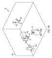
図6Aに示されるように、いくつかの実施形態では、仮想オブジェクト604aおよび/または604bは、中心602の周囲に離間され、および/またはそこに結び付けられてもよい。仮想オブジェクト604aおよび/または604bは、可視(例えば、ユーザに表示される)または不可視(例えば、ユーザに表示されない)であってもよい。いくつかの実施形態では、仮想オブジェクト604aおよび/または604bは、他の仮想オブジェクトと相互作用しなくてもよい。例えば、仮想オブジェクト604aおよび/または604bは、他の仮想オブジェクトと衝突しなくてもよい。仮想オブジェクト604aおよび/または604bは、他の仮想オブジェクトからの光を反射/吸収/透過しなくてもよく、および/または仮想オブジェクト604aおよび/または604bは、他の仮想オブジェクトからの音を反射/吸収/伝送しなくてもよい。いくつかの実施形態では、仮想オブジェクト604aおよび/または604bは、他の仮想オブジェクトと相互作用してもよい。
As shown in FIG. 6A, in some embodiments,
いくつかの実施形態では、仮想オブジェクト604aおよび/または604bは、1つまたはそれを上回る音源と関連付けられてもよい。ある場合には、各仮想オブジェクトは、1つの音源に対応してもよい。例えば、仮想オブジェクト604aおよび/または604bは、仮想的に、音をMRE内のその場所から放出するように構成されてもよい。ある場所から放出されるように知覚され得るように、音源を構成することは、任意の好適な方法を使用して行われることができる。例えば、頭部関連伝達関数(「HRTF」)が、特定の場所から生じる音をシミュレートするために使用されることができる。いくつかの実施形態では、汎用HRTFが、使用されることができる。いくつかの実施形態では、例えば、ユーザの耳の周囲の1つまたはそれを上回るマイクロホン(例えば、MRシステムの1つまたはそれを上回るマイクロホン)が、1人またはそれを上回るユーザ特有のHRTFを決定するために使用されることができる。いくつかの実施形態では、ユーザと仮想音源との間の距離が、好適な方法(例えば、音圧減衰、高周波数減衰、直接および残響音の混合、運動視差等)を使用して、シミュレートされてもよい。いくつかの実施形態では、仮想オブジェクト604aおよび/または604bは、音を点源として放出するように構成されてもよい。いくつかの実施形態では、仮想オブジェクト604aおよび/または604bは、音源の物理的3次元モデルを含んでもよく、音は、音源との相互作用をモデル化することによって生成されてもよい。例えば、仮想オブジェクト604aは、木材本体、弦、調整ペグ等を含む、仮想ギターを含んでもよい。音が、1つまたはそれを上回る弦を弾くことと、アクションが仮想ギターの他のコンポーネントと相互作用する方法とをモデル化することによって、生成されてもよい。
In some embodiments,
いくつかの実施形態では、仮想オブジェクト604aおよび/または604bは、音を全方向性に放出してもよい。いくつかの実施形態では、仮想オブジェクト604aおよび/または604bは、音を指向性に放出してもよい。いくつかの実施形態では、仮想オブジェクト604aおよび/または604bは、音源を含むように構成されてもよく、各音源は、音楽ステムを含んでもよい。いくつかの実施形態では、音楽ステムは、音楽の音全体の恣意的サブセットであってもよい。例えば、またはオーケストラサウンドトラックは、バイオリンステム、チェロステム、バスステム、トランペットステム、ティンパニステム等を含んでもよい。いくつかの実施形態では、マルチチャネルサウンドトラックのチャネルは、ステムとして表されることができる。例えば、2チャネルサウンドトラックは、左ステムおよび右ステムを含んでもよい。いくつかの実施形態では、ミックスの単一トラックが、ステムとして表されてもよい。いくつかの実施形態では、音楽サウンドトラックは、周波数帯域に従って、ステムに分裂されてもよい。ステムは、音全体の任意の恣意的サブセットを表すことができる。
In some embodiments, the
いくつかの実施形態では、仮想オブジェクト604aおよび/または604bは、1つまたはそれを上回るオブジェクト(例えば、中心602および/またはベクトル606)に結び付けられてもよい。例えば、仮想オブジェクト604aは、指定される位置608aに割り当てられてもよい。いくつかの実施形態では、指定される位置608aは、ベクトル606および/または中心602に対する固定点であることができる。いくつかの実施形態では、仮想オブジェクト604bは、指定される位置608bに割り当てられてもよい。いくつかの実施形態では、指定される位置608bは、ベクトル606および/または中心602に対する固定点であることができる。中心602は、点および/または3次元オブジェクトであることができる。いくつかの実施形態では、仮想オブジェクト604aおよび/または604bは、3次元オブジェクトの点(例えば、3次元オブジェクトの中心点またはその表面上の点)に結び付けられてもよい。いくつかの実施形態では、中心602は、任意の好適な点(例えば、ユーザの頭部の中心)に対応してもよい。ユーザの頭部の中心は、頭部装着型MRシステム(既知の寸法を有し得る)の中心および平均頭部寸法を使用して、または他の好適な方法を使用して、推定されてもよい。いくつかの実施形態では、仮想オブジェクト604aおよび/または604bは、指向性インジケータ(例えば、ベクトル606)に結び付けられてもよい。いくつかの実施形態では、仮想オブジェクト604aおよび/または604bは、指定される位置に設置されることができ、これは、中心602および/またはベクトル606に対するその位置を含み、および/またはそれによって定義されてもよい(例えば、球面座標系を使用して)。いくつかの実施形態では、仮想オブジェクト604aおよび/または604bは、中心602および/またはベクトル606が位置(例えば、場所および/または配向)を変化させる場合、その指定される位置から逸脱してもよい。いくつかの実施形態では、仮想オブジェクト604aおよび/または604bは、中心602および/またはベクトル606が位置の変化を停止させた後、例えば、中心602および/またはベクトル606が、所定の時間周期(例えば、5秒)にわたって、固定位置/値を有した後、その指定される位置に戻ってもよい。
In some embodiments,
図6Bに示されるように、ベクトル606は、方向を変化させてもよい。いくつかの実施形態では、指定される位置608aおよび/または608bは、対応して、移動してもよい。例えば、指定される位置608aおよび/または608bは、図6Aにおけるものと同一の図6Bにおける中心602および/またはベクトル606に対する位置であってもよい。いくつかの実施形態では、仮想オブジェクト604aおよび/または604bは、指定される位置608aおよび/または608bの移動を辿ってもよい。例えば、ベクトル606が、図6Aにおける第1の位置から図6Bにおける第2の位置に移動する(例えば、ユーザの頭部の回転を反映させるため)につれて、仮想オブジェクト604aおよび/または604bは、図6Aおよび図6Bの両方において、同一位置に留まってもよい(指定される位置608aおよび/または608bが移動する際でも)。いくつかの実施形態では、仮想オブジェクト604aおよび/または604bは、ベクトル606および/または中心602が移動および/または移動を開始した後、移動を開始してもよい。いくつかの実施形態では、仮想オブジェクト604aおよび/または604bは、ベクトル606および/または中心602が、例えば、所定の時間周期にわたって、移動を停止した後、移動を開始してもよい。図6Cでは、仮想オブジェクト604aおよび/または604bは、ベクトル606および/または中心602に対するその指定される位置に戻ってもよい。例えば、仮想オブジェクト604aおよび/または604bは、図6Aにおけるものと同一の図6Cにおけるベクトル606および/または中心602に対する位置を占有してもよい。
As shown in FIG. 6B,
仮想オブジェクト604aおよび/または604bは、ある時間周期にわたって、その指定される位置608aおよび/または608bから逸脱してもよい。いくつかの実施形態では、ベクトル606および/または中心602が、方向を変化させるにつれて、仮想オブジェクト604aおよび/または604bは、それぞれ、指定される位置608aおよび/または608bの移動経路を「トレース」してもよい。いくつかの実施形態では、仮想オブジェクト604aおよび/または604bは、その現在の位置から、それぞれ、指定される位置608aおよび/または608bまで補間された経路まで追従してもよい。いくつかの実施形態では、仮想オブジェクト604aおよび/または604bは、いったん中心602および/またはベクトル606が、加速および/または移動(例えば、線形および/または角加速)を完全に停止すると、その指定される位置に戻ってもよい。例えば、中心602は、定常点のままであってもよく、ベクトル606は、一定速度において、中心602を中心として回転してもよい(例えば、ユーザが、その頭部を回転させるため)。ある時間周期後、仮想オブジェクト604aおよび/または604bは、ベクトル606が一定速度で移動したままであるという事実にもかかわらず、その指定される位置に戻ってもよい。同様に、いくつかの実施形態では、中心602は、一定速度で移動してもよく(およびベクトル606は、定常のままであってもよい、またはまた、一定速度で移動してもよい)、仮想オブジェクト604aおよび/または604bは、初期加速が中止後、その指定される位置に戻ってもよい。いくつかの実施形態では、仮想オブジェクト604aおよび/または604bは、いったん中心602および/またはベクトル606が移動を停止すると、その指定される位置に戻ってもよい。例えば、ユーザの頭部が、一定速度で回転している場合、仮想オブジェクト604aおよび/または604bは、ユーザがその頭部のスピンを停止するまで、その指定される位置から「遅れ」続けてもよい。いくつかの実施形態では、仮想オブジェクト604aおよび/または604bは、いったん中心602および/またはベクトル606が加速を停止すると、その指定される位置に戻ってもよい。例えば、ユーザの頭部が、回転を開始する、次いで、一定速度で回転し続ける場合、仮想オブジェクト604aおよび/または604bは、最初に、その指定される位置から遅れ、次いで、ユーザの頭部が(例えば、閾値時間周期にわたって)一定速度に到達した後、その指定される位置に到達してもよい。
The
いくつかの実施形態では、1つまたはそれを上回る音源は、それらがユーザの頭部に「弾性的に」結び付けられるかのように、移動してもよい。例えば、ユーザが、その頭部を第1の位置から第2の位置に回転させるにつれて、1つまたはそれを上回る音源は、ユーザの頭部と同一角速度で回転しなくてもよい。いくつかの実施形態では、1つまたはそれを上回る音源は、ユーザの頭部より低速の角速度で回転を開始し、角速度を加速させ、それらがユーザの頭部に対するその初期位置に接近するにつれて、角速度を減速させてもよい。角速度の変化率は、例えば、音設計者によって事前に設定されたレベルにおいて、上限が定められてもよい。これは、音源が非常に迅速に移動することを可能にすること(上記に説明されるような望ましくないオーディオ効果をもたらし得る)と、音源が全く移動しないように防止すること(空間化オーディオの利益を搬送し得ない)との間の平衡を保つことができる。 In some embodiments, the one or more sound sources may move as if they were "elastically" tied to the user's head. For example, as the user rotates his/her head from a first position to a second position, the one or more sound sources may not rotate at the same angular velocity as the user's head. In some embodiments, the one or more sound sources may start rotating at a slower angular velocity than the user's head, accelerate, and decelerate as they approach their initial position relative to the user's head. The rate of change of angular velocity may be capped, for example, at a level preset by the sound designer. This can strike a balance between allowing the sound sources to move very quickly (which may result in undesirable audio effects as described above) and preventing the sound sources from moving at all (which may not convey the benefits of spatialized audio).
いくつかの実施形態では、1つまたはそれを上回る空間化音源に遅延追従を実施させることは、いくつかの利点を有することができる。例えば、ユーザが、空間化音源から相対的位置において逸脱することを可能にすることは、ユーザが、音における差異を知覚することを可能にすることができる。ユーザは、空間化音が、ユーザが空間化音から離れるように方向転換するにつれて、若干より静かになることに気づき、MRE内におけるユーザの没入感を向上され得る。いくつかの実施形態では、遅延追従はまた、所望のオーディオ体験を維持することができる。例えば、ユーザは、音源に接近し、音源の非常に近くに留まることによって、オーディオ体験を非意図的に歪曲させないように防止され得る。音源が、環境に対して静的に設置される場合、ユーザは、音源に接近し得、および空間化装置は、望ましくないことに、ユーザの近接度の結果として、他の音源を過度に抑圧するような音源を提示し得る(特に、ユーザと音源との間の距離がゼロに近づくにつれて)。いくつかの実施形態では、遅延追従は、ユーザが、全体的オーディオ効果を損なわせずに、向上された空間化を体験し得るように、ある遅延後、音源をユーザに対する設定位置に移動させてもよい(例えば、各音源が、概して、相互および/またはユーザから所望の距離に維持され得るため)。 In some embodiments, having one or more spatialized sound sources implement delayed following can have several advantages. For example, allowing the user to deviate in relative position from the spatialized sound source can allow the user to perceive a difference in sound. The user may notice that the spatialized sound becomes slightly quieter as the user turns away from the spatialized sound, enhancing the user's sense of immersion within the MRE. In some embodiments, delayed following can also maintain a desired audio experience. For example, the user may be prevented from unintentionally distorting the audio experience by approaching and remaining very close to the sound source. If the sound source is statically placed relative to the environment, the user may approach the sound source and the spatializer may undesirably present the sound source in a way that overly suppresses other sound sources as a result of the user's proximity (especially as the distance between the user and the sound source approaches zero). In some embodiments, delay tracking may move sound sources to a set position relative to the user after a delay so that the user may experience enhanced spatialization without compromising the overall audio effect (e.g., so that sound sources may generally be maintained at a desired distance from each other and/or the user).
いくつかの実施形態では、仮想オブジェクト604aおよび/または604bは、動的指定される位置を有することができる。例えば、指定される位置608aは、中心602およびベクトル606が定常のままである場合でも、移動する(例えば、ユーザの頭部の軌道を辿る、またはユーザの頭部のより近くおよび/またはそこからさらに遠く離れるように移動する)ように構成されてもよい。いくつかの実施形態では、動的指定される位置は、中心および/またはベクトル(例えば、移動する中心および/またはベクトル)に関連して決定されることができ、仮想オブジェクトは、その指定される位置に向かって、遅延追従様式において移動することができる(例えば、指定される位置の移動をトレースする、および/または経路を補間することによって)。
In some embodiments, the
いくつかの実施形態では、仮想オブジェクト604aおよび/または604bは、ゲームエンジンのためのアセット設計ツール(例えば、Unity)を使用して、その指定される位置に設置されることができる。いくつかの実施形態では、仮想オブジェクト604aおよび/または604bは、ゲームエンジンオブジェクトを含んでもよく、これは、3次元環境(例えば、ゲームエンジンによってサポートされる、MRE)内に設置されてもよい。いくつかの実施形態では、仮想オブジェクト604aおよび/または604bは、親オブジェクトのコンポーネントであってもよい。いくつかの実施形態では、親オブジェクトは、仮想オブジェクトを指定される位置に設置するための対応する中心および/またはベクトル等のパラメータを含んでもよい。いくつかの実施形態では、親オブジェクトは、仮想オブジェクトがその指定される位置に戻るべき速度および/または仮想オブジェクトその指定される位置に戻るべき状況(例えば、一定速度または無運動)に関するパラメータ等の遅延追従パラメータを含んでもよい。いくつかの実施形態では、親オブジェクトは、仮想オブジェクトがその指定される位置を追跡する速度(例えば、仮想オブジェクトが、一定速度で移動、加速、および/または減速すべきかどうか)に関すパラメータを含んでもよい。いくつかの実施形態では、親オブジェクトは、仮想オブジェクトがその現在の位置からその指定される位置まで辿り得る経路を決定するためのパラメータを含んでもよい(例えば、線形および/または指数関数的補間を使用して)。いくつかの実施形態では、仮想オブジェクト(例えば、仮想オブジェクト604aおよび604b)は、その独自のそのようなパラメータを含んでもよい。
In some embodiments, the
いくつかの実施形態では、ゲームエンジンは、仮想オブジェクト604aおよび604bのいくつかまたは全ての性質(例えば、仮想オブジェクト604aおよび604bの現在および/または指定される場所)を維持してもよい。いくつかの実施形態では、仮想オブジェクト604aおよび604bの現在の場所(例えば、親オブジェクトの場所および/または性質を通して、または、直接、仮想オブジェクト604および604bの場所および/または性質)が、空間化および/またはレンダリングエンジンに通過されてもよい。例えば、空間化および/またはレンダリングエンジンは、仮想オブジェクト604aから発出される音および仮想オブジェクト604aの現在の位置を受信してもよい。空間化および/またはレンダリングエンジンは、入力を処理し、音を仮想オブジェクト604aの場所から生じるように知覚するように構成され得る、空間化音を含み得る、出力を生産してもよい。空間化および/またはレンダリングエンジンは、限定ではないが、頭部関連伝達関数および/または距離減衰技法を含む、任意の好適な技法を使用して、空間化音をレンダリングしてもよい。
In some embodiments, the game engine may maintain some or all properties of the
いくつかの実施形態では、空間化および/またはレンダリングエンジンは、データ構造を受信し、遅延追従空間化音をレンダリングしてもよい。例えば、遅延追従データ構造は、頭部姿勢に対する位置に関するパラメータおよび/またはメタデータおよび/または遅延追従パラメータとともに、データフォーマットを含んでもよい。いくつかの実施形態では、MRシステム上で起動するアプリケーションは、1つまたはそれを上回る遅延追従データ構造を空間化および/またはレンダリングエンジンに送信し、遅延追従空間化音をレンダリングしてもよい。 In some embodiments, a spatialization and/or rendering engine may receive the data structure and render the delayed-following spatialized sound. For example, the delayed-following data structure may include a data format along with parameters and/or metadata and/or delayed-following parameters related to position relative to head pose. In some embodiments, an application running on the MR system may send one or more delayed-following data structures to a spatialization and/or rendering engine to render the delayed-following spatialized sound.
いくつかの実施形態では、サウンドトラックが、遅延追従データ構造の中に処理されてもよい。例えば、5.1チャネルサウンドトラックが、6つのステムに分裂されてもよく、各ステムは、1つまたはそれを上回る仮想オブジェクト(例えば、仮想オブジェクト604aおよび604b)に割り当てられてもよい。各ステム/仮想オブジェクトは、5.1チャネルサラウンド音のための事前に構成された配向に設置されてもよい(例えば、中心スピーカステムは、ユーザの正面の約20フィートにおいて、ユーザの顔の真正面に設置されてもよい)。いくつかの実施形態では、遅延追従データ構造は、次いで、空間化および/またはレンダリングエンジンによって使用され、遅延追従空間化音をレンダリングしてもよい。
In some embodiments, the soundtrack may be processed into a delay-following data structure. For example, a 5.1 channel soundtrack may be split into six stems, and each stem may be assigned to one or more virtual objects (e.g.,
いくつかの実施形態では、遅延追従空間化音は、1人を上回るユーザのためにレンダリングされてもよい。例えば、第1のユーザを囲繞するように構成される、仮想オブジェクトのセットは、第2のユーザに知覚可能であってもよい。第2のユーザは、遅延様式において、第1のユーザに続いて、仮想オブジェクト/音源を観察してもよい。いくつかの実施形態では、仮想オブジェクト/音源のセットは、1人を上回るユーザを囲繞するように構成されてもよい。例えば、中心点は、第1のユーザの頭部と第2のユーザの頭部との間の中心点として計算されてもよい。ベクトルは、各ユーザに面した方向を表すベクトル間の平均ベクトルとして計算されてもよい。1つまたはそれを上回る仮想オブジェクト/音源が、動的に計算される中心点および/またはベクトルに対して設置されてもよい。 In some embodiments, delayed-following spatialized sound may be rendered for more than one user. For example, a set of virtual objects configured to surround a first user may be perceptible to a second user. The second user may observe the virtual objects/sound sources following the first user in a delayed manner. In some embodiments, a set of virtual objects/sound sources may be configured to surround more than one user. For example, a center point may be calculated as a center point between the head of the first user and the head of the second user. A vector may be calculated as an average vector between vectors representing the facing direction of each user. One or more virtual objects/sound sources may be placed relative to the dynamically calculated center point and/or vector.
2つの仮想オブジェクトが、図6A-6Cに示されるが、任意の数の仮想オブジェクトおよび/または音源が、使用されてもよいことが検討される。いくつかの実施形態では、各仮想オブジェクトおよび/または音源は、その独自の別個のパラメータを有してもよい。中心点/オブジェクトおよびベクトルは、位置仮想オブジェクトを位置付けるために使用されるが、任意の適切な座標系(例えば、デカルト、球状等)も、使用されてもよい。 Although two virtual objects are shown in Figures 6A-6C, it is contemplated that any number of virtual objects and/or sound sources may be used. In some embodiments, each virtual object and/or sound source may have its own separate parameters. A center point/object and vector are used to position the position virtual object, although any suitable coordinate system (e.g., Cartesian, spherical, etc.) may also be used.
システム、方法、およびコンピュータ可読媒体が、開示される。いくつかの実施例によると、システムは、スピーカおよび1つまたはそれを上回るセンサを有する、ウェアラブル頭部デバイスと、1つまたはそれを上回るセンサに基づいて、第1の時間におけるユーザの頭部の第1の位置を決定することと、1つまたはそれを上回るセンサに基づいて、第1の時間より後の第2の時間におけるユーザの頭部の第2の位置を決定することと、第1の位置と第2の位置との間の差異に基づいて、オーディオ信号を決定することと、スピーカを介して、オーディオ信号をユーザに提示することとを含む、方法を実施するように構成される、1つまたはそれを上回るプロセッサとを備え、オーディオ信号を決定することは、仮想環境内のオーディオ信号の起点を決定することを含み、オーディオ信号をユーザに提示することは、決定された起点から生じるかのように、オーディオ信号を提示することを含み、オーディオ信号の起点を決定することは、オフセットをユーザの頭部の位置に適用することを含む。いくつかの実施例では、オーディオ信号の起点を決定することはさらに、ユーザの頭部の位置の変化率に基づいて、オーディオ信号の起点を決定することを含む。いくつかの実施例では、オーディオ信号の起点を決定することはさらに、変化率が閾値を超えることの決定に従って、起点が第1の起点を備えることを決定することと、変化率が閾値を超えないことの決定に従って、起点が第1の起点と異なる第2の起点を備えることを決定することとを含む。いくつかの実施例では、オーディオ信号の起点を決定することはさらに、オフセットの大きさが閾値を下回ることの決定に従って、起点が第1の起点を備えることを決定することと、オフセットの大きさが閾値を下回らないことの決定に従って、起点が第1の起点と異なる第2の起点を備えることを決定することとを含む。いくつかの実施例では、オーディオ信号を決定することはさらに、仮想環境内の速度を決定することを含み、オーディオ信号をユーザに提示することはさらに、起点が決定された速度で運動するかのように、オーディオ信号を提示することを含む。いくつかの実施例では、速度を決定することは、ユーザの頭部の第1の位置とユーザの頭部の第2の位置との間の差異に基づいて、速度を決定することを含む。いくつかの実施例では、オフセットは、ユーザの頭部の第1の位置に基づいて決定される。 A system, method, and computer-readable medium are disclosed. According to some embodiments, the system includes a wearable head device having a speaker and one or more sensors, and one or more processors configured to implement a method including determining a first position of a user's head at a first time based on the one or more sensors, determining a second position of the user's head at a second time after the first time based on the one or more sensors, determining an audio signal based on a difference between the first position and the second position, and presenting the audio signal to the user via the speaker, where determining the audio signal includes determining an origin of the audio signal within the virtual environment, and presenting the audio signal to the user includes presenting the audio signal as if originating from the determined origin, and determining the origin of the audio signal includes applying an offset to the position of the user's head. In some embodiments, determining the origin of the audio signal further includes determining the origin of the audio signal based on a rate of change of the position of the user's head. In some examples, determining an origin of the audio signal further includes determining that the origin comprises a first origin in accordance with a determination that the rate of change exceeds a threshold, and determining that the origin comprises a second origin different from the first origin in accordance with a determination that the rate of change does not exceed a threshold. In some examples, determining an origin of the audio signal further includes determining that the origin comprises a first origin in accordance with a determination that the magnitude of the offset is below a threshold, and determining that the origin comprises a second origin different from the first origin in accordance with a determination that the magnitude of the offset is not below a threshold. In some examples, determining the audio signal further includes determining a velocity within the virtual environment, and presenting the audio signal to the user further includes presenting the audio signal as if the origin were moving at the determined velocity. In some examples, determining the velocity includes determining the velocity based on a difference between a first position of the user's head and a second position of the user's head. In some examples, the offset is determined based on the first position of the user's head.
いくつかの実施例によると、オーディオをウェアラブル頭部デバイスのユーザに提示する方法は、ウェアラブル頭部デバイスの1つまたはそれを上回るセンサに基づいて、第1の時間におけるユーザの頭部の第1の位置を決定することと、1つまたはそれを上回るセンサに基づいて、第1の時間より後の第2の時間におけるユーザの頭部の第2の位置を決定することと、第1の位置と第2の位置との間の差異に基づいて、オーディオ信号を決定することと、ウェアラブル頭部デバイスのスピーカを介して、オーディオ信号をユーザに提示することとを含み、オーディオ信号を決定することは、仮想環境内のオーディオ信号の起点を決定することを含み、オーディオ信号をユーザに提示することは、決定された起点から生じるかのように、オーディオ信号を提示することを含み、オーディオ信号の起点を決定することは、オフセットをユーザの頭部の位置に適用することを含む。いくつかの実施例では、オーディオ信号の起点を決定することはさらに、ユーザの頭部の位置の変化率に基づいて、オーディオ信号の起点を決定することを含む。いくつかの実施例では、オーディオ信号の起点を決定することはさらに、変化率が閾値を超えることの決定に従って、起点が第1の起点を備えることを決定することと、変化率が閾値を超えないことの決定に従って、起点が第1の起点と異なる第2の起点を備えることを決定することとを含む。いくつかの実施例では、オーディオ信号の起点を決定することはさらに、オフセットの大きさが閾値を下回ることの決定に従って、起点が第1の起点を備えることを決定することと、オフセットの大きさが閾値を下回らないことの決定に従って、起点が第1の起点と異なる第2の起点を備えることを決定することとを含む。いくつかの実施例では、オーディオ信号を決定することはさらに、仮想環境内の速度を決定することを含み、オーディオ信号をユーザに提示することはさらに、起点が決定された速度で運動するかのように、オーディオ信号を提示することを含む。いくつかの実施例では、速度を決定することは、ユーザの頭部の第1の位置とユーザの頭部の第2の位置との間の差異に基づいて、速度を決定することを含む。いくつかの実施例では、オフセットは、ユーザの頭部の第1の位置に基づいて決定される。 According to some embodiments, a method of presenting audio to a user of a wearable head device includes determining a first position of the user's head at a first time based on one or more sensors of the wearable head device, determining a second position of the user's head at a second time, later than the first time, based on the one or more sensors, determining an audio signal based on a difference between the first position and the second position, and presenting the audio signal to the user via a speaker of the wearable head device, where determining the audio signal includes determining an origin of the audio signal within the virtual environment, and presenting the audio signal to the user includes presenting the audio signal as if originating from the determined origin, and determining the origin of the audio signal includes applying an offset to the position of the user's head. In some embodiments, determining the origin of the audio signal further includes determining the origin of the audio signal based on a rate of change of the position of the user's head. In some examples, determining an origin of the audio signal further includes determining that the origin comprises a first origin in accordance with a determination that the rate of change exceeds a threshold, and determining that the origin comprises a second origin different from the first origin in accordance with a determination that the rate of change does not exceed a threshold. In some examples, determining an origin of the audio signal further includes determining that the origin comprises a first origin in accordance with a determination that the magnitude of the offset is below a threshold, and determining that the origin comprises a second origin different from the first origin in accordance with a determination that the magnitude of the offset is not below a threshold. In some examples, determining the audio signal further includes determining a velocity within the virtual environment, and presenting the audio signal to the user further includes presenting the audio signal as if the origin were moving at the determined velocity. In some examples, determining the velocity includes determining the velocity based on a difference between a first position of the user's head and a second position of the user's head. In some examples, the offset is determined based on the first position of the user's head.
いくつかの実施例によると、非一過性コンピュータ可読媒体は、1つまたはそれを上回るプロセッサによって実行されると、1つまたはそれを上回るプロセッサに、オーディオをウェアラブル頭部デバイスのユーザに提示する方法を実施させる、命令を記憶し、本方法は、ウェアラブル頭部デバイスの1つまたはそれを上回るセンサに基づいて、第1の時間におけるユーザの頭部の第1の位置を決定することと、1つまたはそれを上回るセンサに基づいて、第1の時間より後の第2の時間におけるユーザの頭部の第2の位置を決定することと、第1の位置と第2の位置との間の差異に基づいて、オーディオ信号を決定することと、ウェアラブル頭部デバイスのスピーカを介して、オーディオ信号をユーザに提示することとを含み、オーディオ信号を決定することは、仮想環境内のオーディオ信号の起点を決定することを含み、オーディオ信号をユーザに提示することは、決定された起点から生じるかのように、オーディオ信号を提示することを含み、オーディオ信号の起点を決定することは、オフセットをユーザの頭部の位置に適用することを含む。いくつかの実施例では、オーディオ信号の起点を決定することはさらに、ユーザの頭部の位置の変化率に基づいて、オーディオ信号の起点を決定することを含む。いくつかの実施例では、オーディオ信号の起点を決定することはさらに、変化率が閾値を超えることの決定に従って、起点が第1の起点を備えることを決定することと、変化率が閾値を超えないことの決定に従って、起点が第1の起点と異なる第2の起点を備えることを決定することとを含む。いくつかの実施例では、オーディオ信号の起点を決定することはさらに、オフセットの大きさが閾値を下回ることの決定に従って、起点が第1の起点を備えることを決定することと、オフセットの大きさが閾値を下回らないことの決定に従って、起点が第1の起点と異なる第2の起点を備えることを決定することとを含む。いくつかの実施例では、オーディオ信号を決定することはさらに、仮想環境内の速度を決定することを含み、オーディオ信号をユーザに提示することはさらに、起点が決定された速度で運動するかのように、オーディオ信号を提示することを含む。いくつかの実施例では、速度を決定することは、ユーザの頭部の第1の位置とユーザの頭部の第2の位置との間の差異に基づいて、速度を決定することを含む。いくつかの実施例では、オフセットは、ユーザの頭部の第1の位置に基づいて決定される。 According to some embodiments, a non-transitory computer-readable medium stores instructions that, when executed by one or more processors, cause the one or more processors to perform a method of presenting audio to a user of a wearable head device, the method including: determining a first position of the user's head at a first time based on one or more sensors of the wearable head device; determining a second position of the user's head at a second time, later than the first time, based on the one or more sensors; determining an audio signal based on a difference between the first position and the second position; and presenting the audio signal to the user via a speaker of the wearable head device, wherein determining the audio signal includes determining an origin of the audio signal within the virtual environment; presenting the audio signal to the user includes presenting the audio signal as if originating from the determined origin; and determining the origin of the audio signal includes applying an offset to the position of the user's head. In some embodiments, determining the origin of the audio signal further includes determining the origin of the audio signal based on a rate of change of the position of the user's head. In some examples, determining an origin of the audio signal further includes determining that the origin comprises a first origin in accordance with a determination that the rate of change exceeds a threshold, and determining that the origin comprises a second origin different from the first origin in accordance with a determination that the rate of change does not exceed a threshold. In some examples, determining an origin of the audio signal further includes determining that the origin comprises a first origin in accordance with a determination that the magnitude of the offset is below a threshold, and determining that the origin comprises a second origin different from the first origin in accordance with a determination that the magnitude of the offset is not below a threshold. In some examples, determining the audio signal further includes determining a velocity within the virtual environment, and presenting the audio signal to the user further includes presenting the audio signal as if the origin were moving at the determined velocity. In some examples, determining the velocity includes determining the velocity based on a difference between a first position of the user's head and a second position of the user's head. In some examples, the offset is determined based on the first position of the user's head.
開示される実施例は、付随の図面を参照して完全に説明されたが、種々の変更および修正が、当業者に明白となるであろうことに留意されたい。例えば、1つまたはそれを上回る実装の要素は、組み合わせられ、削除され、修正され、または補完され、さらなる実装を形成してもよい。そのような変更および修正は、添付の請求項によって定義されるような開示される実施例の範囲内に含まれるものとして理解されるべきである。 Although the disclosed embodiments have been fully described with reference to the accompanying drawings, it should be noted that various changes and modifications will be apparent to those skilled in the art. For example, elements of one or more implementations may be combined, deleted, modified, or supplemented to form further implementations. Such changes and modifications should be understood as being included within the scope of the disclosed embodiments as defined by the appended claims.
Claims (17)
スピーカおよび1つまたはそれを上回るセンサを有するウェアラブル頭部デバイスと、
1つまたはそれを上回るプロセッサであって、
前記1つまたはそれを上回るセンサに基づいて、第1の時間におけるユーザの頭部の第1の位置を決定することと、
前記1つまたはそれを上回るセンサに基づいて、前記第1の時間より後の第2の時間における前記ユーザの頭部の第2の位置を決定することと、
前記第1の位置と前記第2の位置との間の差異に基づいて、オーディオ信号を決定することと、
前記スピーカを介して、前記オーディオ信号を前記ユーザに提示することと
を含む方法を実施するように構成される、1つまたはそれを上回るプロセッサと
を備え、
前記オーディオ信号を決定することは、仮想環境内の前記オーディオ信号の起点を決定することを含み、
前記オーディオ信号を前記ユーザに提示することは、前記決定された起点から生じるかのように、前記オーディオ信号を提示することを含み、
前記オーディオ信号の前記起点を決定することは、オフセットを前記ユーザの頭部の位置に適用することを含み、
前記オーディオ信号を決定することは、前記仮想環境内の速度を決定することをさらに含み、
前記オーディオ信号を前記ユーザに提示することは、前記起点が遅延して前記決定された速度で運動するかのように、前記オーディオ信号を提示することをさらに含み、
前記速度を決定することは、前記ユーザの頭部の前記第1の位置と前記ユーザの頭部の前記第2の位置との間の差異に基づいて、前記速度を決定することを含み、
前記オーディオ信号の前記起点は、前記遅延の後に前記決定された速度に基づいて移動し、前記起点が移動する間において、前記仮想環境内の前記起点の移動の場所は、前記仮想環境内の前記オーディオ信号と関連付けられるオブジェクトの1つまたはそれを上回る場所と異なる、システム。 1. A system comprising:
a wearable head device having a speaker and one or more sensors;
One or more processors,
determining a first position of a user's head at a first time based on the one or more sensors;
determining a second position of the user's head at a second time, after the first time, based on the one or more sensors; and
determining an audio signal based on a difference between the first position and the second position;
presenting the audio signal to the user via the speaker; and
determining the audio signal includes determining an origin of the audio signal within a virtual environment;
presenting the audio signal to the user includes presenting the audio signal as if originating from the determined origin;
Determining the origin of the audio signal includes applying an offset to a position of the user's head;
determining the audio signal further comprises determining a velocity within the virtual environment;
presenting the audio signal to the user further includes presenting the audio signal as if the origin were moving at the determined velocity with a delay;
determining the velocity includes determining the velocity based on a difference between the first position of the user's head and the second position of the user's head;
The system, wherein the origin of the audio signal moves based on the determined velocity after the delay, and while the origin is moving, a location of the movement of the origin within the virtual environment differs from a location of one or more objects associated with the audio signal in the virtual environment .
前記変化率が閾値を超えることの決定に従って、前記起点が第1の起点を備えることを決定することと、
前記変化率が前記閾値を超えないことの決定に従って、前記起点が前記第1の起点と異なる第2の起点を備えることを決定することと
をさらに含む、請求項2に記載のシステム。 Determining the origin of the audio signal comprises:
determining that the origin comprises a first origin in accordance with determining that the rate of change exceeds a threshold;
and determining, in accordance with a determination that the rate of change does not exceed the threshold, that the origin comprises a second origin different from the first origin.
前記オフセットの大きさが閾値を下回ることの決定に従って、前記起点が第1の起点を備えることを決定することと、
前記オフセットの大きさが前記閾値を下回らないことの決定に従って、前記起点が前記第1の起点と異なる第2の起点を備えることを決定することと
をさらに含む、請求項1に記載のシステム。 Determining the origin of the audio signal comprises:
determining that the origin comprises a first origin in accordance with determining that the magnitude of the offset is below a threshold; and
and determining, in accordance with determining that the magnitude of the offset is not below the threshold, that the origin comprises a second origin different from the first origin.
前記ウェアラブル頭部デバイスの1つまたはそれを上回るセンサに基づいて、第1の時間における前記ユーザの頭部の第1の位置を決定することと、
前記1つまたはそれを上回るセンサに基づいて、前記第1の時間より後の第2の時間における前記ユーザの頭部の第2の位置を決定することと、
前記第1の位置と前記第2の位置との間の差異に基づいて、オーディオ信号を決定することと、
前記ウェアラブル頭部デバイスのスピーカを介して、前記オーディオ信号を前記ユーザに提示することと
を含み、
前記オーディオ信号を決定することは、仮想環境内の前記オーディオ信号の起点を決定することを含み、
前記オーディオ信号を前記ユーザに提示することは、前記決定された起点から生じるかのように、前記オーディオ信号を提示することを含み、
前記オーディオ信号の前記起点を決定することは、オフセットを前記ユーザの頭部の位置に適用することを含み、
前記オーディオ信号を決定することは、前記仮想環境内の速度を決定することをさらに含み、
前記オーディオ信号を前記ユーザに提示することは、前記起点が遅延して前記決定された速度で運動するかのように、前記オーディオ信号を提示することをさらに含み、
前記速度を決定することは、前記ユーザの頭部の前記第1の位置と前記ユーザの頭部の前記第2の位置との間の差異に基づいて、前記速度を決定することを含み、
前記オーディオ信号の前記起点は、前記遅延の後に前記決定された速度に基づいて移動し、前記起点が移動する間において、前記仮想環境内の前記起点の移動の場所は、前記仮想環境内の前記オーディオ信号と関連付けられるオブジェクトの1つまたはそれを上回る場所と異なる、方法。 1. A method for presenting audio to a user of a wearable head device, the method comprising:
determining a first position of the user's head at a first time based on one or more sensors of the wearable head device;
determining a second position of the user's head at a second time, after the first time, based on the one or more sensors; and
determining an audio signal based on a difference between the first position and the second position;
presenting the audio signal to the user via a speaker of the wearable head device;
determining the audio signal includes determining an origin of the audio signal within a virtual environment;
presenting the audio signal to the user includes presenting the audio signal as if originating from the determined origin;
Determining the origin of the audio signal includes applying an offset to a position of the user's head;
determining the audio signal further comprises determining a velocity within the virtual environment;
presenting the audio signal to the user further includes presenting the audio signal as if the origin were moving at the determined velocity with a delay;
determining the velocity includes determining the velocity based on a difference between the first position of the user's head and the second position of the user's head;
The method of claim 1, wherein the origin of the audio signal moves based on the determined speed after the delay, and while the origin is moving, a location of the movement of the origin within the virtual environment differs from a location of one or more objects associated with the audio signal in the virtual environment .
前記変化率が閾値を超えることの決定に従って、前記起点が第1の起点を備えることを決定することと、
前記変化率が前記閾値を超えないことの決定に従って、前記起点が前記第1の起点と異なる第2の起点を備えることを決定することと
をさらに含む、請求項8に記載の方法。 Determining the origin of the audio signal comprises:
determining that the origin comprises a first origin in accordance with determining that the rate of change exceeds a threshold;
and determining, in accordance with a determination that the rate of change does not exceed the threshold, that the origin comprises a second origin that is different from the first origin.
前記オフセットの大きさが閾値を下回ることの決定に従って、前記起点が第1の起点を備えることを決定することと、
前記オフセットの大きさが前記閾値を下回らないことの決定に従って、前記起点が前記第1の起点と異なる第2の起点を備えることを決定することと
をさらに含む、請求項7に記載の方法。 Determining the origin of the audio signal comprises:
determining that the origin comprises a first origin in accordance with determining that the magnitude of the offset is below a threshold; and
and determining, in accordance with determining that the magnitude of the offset is not below the threshold, that the origin comprises a second origin different from the first origin.
前記ウェアラブル頭部デバイスの1つまたはそれを上回るセンサに基づいて、第1の時間における前記ユーザの頭部の第1の位置を決定することと、
前記1つまたはそれを上回るセンサに基づいて、前記第1の時間より後の第2の時間における前記ユーザの頭部の第2の位置を決定することと、
前記第1の位置と前記第2の位置との間の差異に基づいて、オーディオ信号を決定することと、
前記ウェアラブル頭部デバイスのスピーカを介して、前記オーディオ信号を前記ユーザに提示することと
を含み、
前記オーディオ信号を決定することは、仮想環境内の前記オーディオ信号の起点を決定することを含み、
前記オーディオ信号を前記ユーザに提示することは、前記決定された起点から生じるかのように、前記オーディオ信号を提示することを含み、
前記オーディオ信号の前記起点を決定することは、オフセットを前記ユーザの頭部の位置に適用することを含み、
前記オーディオ信号を決定することは、前記仮想環境内の速度を決定することをさらに含み、
前記オーディオ信号を前記ユーザに提示することは、前記起点が遅延して前記決定された速度で運動するかのように、前記オーディオ信号を提示することをさらに含み、
前記速度を決定することは、前記ユーザの頭部の前記第1の位置と前記ユーザの頭部の前記第2の位置との間の差異に基づいて、前記速度を決定することを含み、
前記オーディオ信号の前記起点は、前記遅延の後に前記決定された速度に基づいて移動し、前記起点が移動する間において、前記仮想環境内の前記起点の移動の場所は、前記仮想環境内の前記オーディオ信号と関連付けられるオブジェクトの1つまたはそれを上回る場所と異なる、非一過性コンピュータ可読媒体。 1. A non-transitory computer readable medium having instructions stored thereon that, when executed by one or more processors, cause the one or more processors to perform a method of presenting audio to a user of a wearable head device, the method comprising:
determining a first position of the user's head at a first time based on one or more sensors of the wearable head device;
determining a second position of the user's head at a second time, after the first time, based on the one or more sensors; and
determining an audio signal based on a difference between the first position and the second position;
presenting the audio signal to the user via a speaker of the wearable head device;
determining the audio signal includes determining an origin of the audio signal within a virtual environment;
presenting the audio signal to the user includes presenting the audio signal as if originating from the determined origin;
Determining the origin of the audio signal includes applying an offset to a position of the user's head;
determining the audio signal further comprises determining a velocity within the virtual environment;
presenting the audio signal to the user further includes presenting the audio signal as if the origin were moving at the determined velocity with a delay;
determining the velocity includes determining the velocity based on a difference between the first position of the user's head and the second position of the user's head;
A non-transitory computer-readable medium, wherein the origin of the audio signal moves based on the determined speed after the delay, and while the origin is moving, a location of the movement of the origin within the virtual environment differs from a location of one or more objects associated with the audio signal in the virtual environment .
前記変化率が閾値を超えることの決定に従って、前記起点が第1の起点を備えることを決定することと、
前記変化率が前記閾値を超えないことの決定に従って、前記起点が前記第1の起点と異なる第2の起点を備えることを決定することと
をさらに含む、請求項14に記載の非一過性コンピュータ可読媒体。 Determining the origin of the audio signal comprises:
determining that the origin comprises a first origin in accordance with determining that the rate of change exceeds a threshold;
and determining, in accordance with a determination that the rate of change does not exceed the threshold, that the origin comprises a second origin that is different from the first origin.
前記オフセットの大きさが閾値を下回ることの決定に従って、前記起点が第1の起点を備えることを決定することと、
前記オフセットの大きさが前記閾値を下回らないことの決定に従って、前記起点が前記第1の起点と異なる第2の起点を備えることを決定することと
をさらに含む、請求項13に記載の非一過性コンピュータ可読媒体。 Determining the origin of the audio signal comprises:
determining that the origin comprises a first origin in accordance with determining that the magnitude of the offset is below a threshold; and
and determining, in accordance with determining that the magnitude of the offset is not below the threshold, that the origin comprises a second origin that is different from the first origin.
Applications Claiming Priority (3)
| Application Number | Priority Date | Filing Date | Title |
|---|---|---|---|
| US202062976986P | 2020-02-14 | 2020-02-14 | |
| US62/976,986 | 2020-02-14 | ||
| PCT/US2021/017971 WO2021163573A1 (en) | 2020-02-14 | 2021-02-12 | Delayed audio following |
Publications (3)
| Publication Number | Publication Date |
|---|---|
| JP2023514571A JP2023514571A (en) | 2023-04-06 |
| JP2023514571A5 JP2023514571A5 (en) | 2024-02-19 |
| JP7635249B2 true JP7635249B2 (en) | 2025-02-25 |
Family
ID=77273537
Family Applications (1)
| Application Number | Title | Priority Date | Filing Date |
|---|---|---|---|
| JP2022548902A Active JP7635249B2 (en) | 2020-02-14 | 2021-02-12 | Latent Audio Tracking |
Country Status (4)
| Country | Link |
|---|---|
| EP (1) | EP4104457A4 (en) |
| JP (1) | JP7635249B2 (en) |
| CN (1) | CN115398935A (en) |
| WO (1) | WO2021163573A1 (en) |
Families Citing this family (1)
| Publication number | Priority date | Publication date | Assignee | Title |
|---|---|---|---|---|
| CN117956373A (en) * | 2022-10-27 | 2024-04-30 | 安克创新科技股份有限公司 | Audio processing method, audio playback device, and computer-readable storage medium |
Citations (6)
| Publication number | Priority date | Publication date | Assignee | Title |
|---|---|---|---|---|
| JP2012518313A (en) | 2009-02-13 | 2012-08-09 | コーニンクレッカ フィリップス エレクトロニクス エヌ ヴィ | Head tracking for mobile applications |
| JP2013005021A (en) | 2011-06-13 | 2013-01-07 | Sony Corp | Information processor, information processing method, and program |
| JP2014127936A (en) | 2012-12-27 | 2014-07-07 | Denso Corp | Sound image localization device and program |
| JP2016021169A (en) | 2014-07-15 | 2016-02-04 | Kddi株式会社 | Portable terminal for arranging virtual sound source at provision information position, voice presentation program, and voice presentation method |
| US20190268711A1 (en) | 2018-02-28 | 2019-08-29 | Google Llc | Spatial audio to enable safe headphone use during exercise and commuting |
| US20190335290A1 (en) | 2016-06-30 | 2019-10-31 | Nokia Technologies Oy | Providing audio signals in a virtual environment |
Family Cites Families (6)
| Publication number | Priority date | Publication date | Assignee | Title |
|---|---|---|---|---|
| US10595147B2 (en) * | 2014-12-23 | 2020-03-17 | Ray Latypov | Method of providing to user 3D sound in virtual environment |
| US10123147B2 (en) * | 2016-01-27 | 2018-11-06 | Mediatek Inc. | Enhanced audio effect realization for virtual reality |
| US10028071B2 (en) * | 2016-09-23 | 2018-07-17 | Apple Inc. | Binaural sound reproduction system having dynamically adjusted audio output |
| JP2018082308A (en) * | 2016-11-16 | 2018-05-24 | ソニー株式会社 | Information processing apparatus, method and program |
| CN117041607A (en) * | 2018-07-13 | 2023-11-10 | 诺基亚技术有限公司 | Method and apparatus for audio rendering |
| US10638251B2 (en) * | 2018-08-06 | 2020-04-28 | Facebook Technologies, Llc | Customizing head-related transfer functions based on monitored responses to audio content |
-
2021
- 2021-02-12 WO PCT/US2021/017971 patent/WO2021163573A1/en not_active Ceased
- 2021-02-12 CN CN202180027858.5A patent/CN115398935A/en active Pending
- 2021-02-12 JP JP2022548902A patent/JP7635249B2/en active Active
- 2021-02-12 EP EP21754163.0A patent/EP4104457A4/en active Pending
Patent Citations (6)
| Publication number | Priority date | Publication date | Assignee | Title |
|---|---|---|---|---|
| JP2012518313A (en) | 2009-02-13 | 2012-08-09 | コーニンクレッカ フィリップス エレクトロニクス エヌ ヴィ | Head tracking for mobile applications |
| JP2013005021A (en) | 2011-06-13 | 2013-01-07 | Sony Corp | Information processor, information processing method, and program |
| JP2014127936A (en) | 2012-12-27 | 2014-07-07 | Denso Corp | Sound image localization device and program |
| JP2016021169A (en) | 2014-07-15 | 2016-02-04 | Kddi株式会社 | Portable terminal for arranging virtual sound source at provision information position, voice presentation program, and voice presentation method |
| US20190335290A1 (en) | 2016-06-30 | 2019-10-31 | Nokia Technologies Oy | Providing audio signals in a virtual environment |
| US20190268711A1 (en) | 2018-02-28 | 2019-08-29 | Google Llc | Spatial audio to enable safe headphone use during exercise and commuting |
Also Published As
| Publication number | Publication date |
|---|---|
| WO2021163573A1 (en) | 2021-08-19 |
| CN115398935A (en) | 2022-11-25 |
| EP4104457A1 (en) | 2022-12-21 |
| EP4104457A4 (en) | 2023-07-19 |
| JP2023514571A (en) | 2023-04-06 |
Similar Documents
| Publication | Publication Date | Title |
|---|---|---|
| JP7673309B2 (en) | Dual listener positioning for mixed reality | |
| JP7629975B2 (en) | Echo fingerprint estimation | |
| JP7642701B2 (en) | Mixed Reality Virtual Reverberation | |
| JP7778260B2 (en) | Dynamic collocation of virtual content | |
| US11477599B2 (en) | Delayed audio following | |
| JP7656754B2 (en) | Environmental Sound Persistence | |
| US20240414494A1 (en) | Delayed audio following | |
| EP3719613A1 (en) | Rendering captions for media content | |
| JP2023514571A (en) | delayed audio tracking |
Legal Events
| Date | Code | Title | Description |
|---|---|---|---|
| A521 | Request for written amendment filed |
Free format text: JAPANESE INTERMEDIATE CODE: A523 Effective date: 20240208 |
|
| A621 | Written request for application examination |
Free format text: JAPANESE INTERMEDIATE CODE: A621 Effective date: 20240208 |
|
| A871 | Explanation of circumstances concerning accelerated examination |
Free format text: JAPANESE INTERMEDIATE CODE: A871 Effective date: 20240208 |
|
| A131 | Notification of reasons for refusal |
Free format text: JAPANESE INTERMEDIATE CODE: A131 Effective date: 20240426 |
|
| A521 | Request for written amendment filed |
Free format text: JAPANESE INTERMEDIATE CODE: A523 Effective date: 20240725 |
|
| A02 | Decision of refusal |
Free format text: JAPANESE INTERMEDIATE CODE: A02 Effective date: 20240919 |
|
| A521 | Request for written amendment filed |
Free format text: JAPANESE INTERMEDIATE CODE: A523 Effective date: 20250115 |
|
| TRDD | Decision of grant or rejection written | ||
| A01 | Written decision to grant a patent or to grant a registration (utility model) |
Free format text: JAPANESE INTERMEDIATE CODE: A01 Effective date: 20250204 |
|
| A61 | First payment of annual fees (during grant procedure) |
Free format text: JAPANESE INTERMEDIATE CODE: A61 Effective date: 20250212 |
|
| R150 | Certificate of patent or registration of utility model |
Ref document number: 7635249 Country of ref document: JP Free format text: JAPANESE INTERMEDIATE CODE: R150 |