JP7635258B2 - Refining Equipment - Google Patents
Refining Equipment Download PDFInfo
- Publication number
- JP7635258B2 JP7635258B2 JP2022563802A JP2022563802A JP7635258B2 JP 7635258 B2 JP7635258 B2 JP 7635258B2 JP 2022563802 A JP2022563802 A JP 2022563802A JP 2022563802 A JP2022563802 A JP 2022563802A JP 7635258 B2 JP7635258 B2 JP 7635258B2
- Authority
- JP
- Japan
- Prior art keywords
- tank
- line
- mother liquor
- crystallization
- slurry
- Prior art date
- Legal status (The legal status is an assumption and is not a legal conclusion. Google has not performed a legal analysis and makes no representation as to the accuracy of the status listed.)
- Active
Links
Images


Classifications
-
- C—CHEMISTRY; METALLURGY
- C07—ORGANIC CHEMISTRY
- C07C—ACYCLIC OR CARBOCYCLIC COMPOUNDS
- C07C51/00—Preparation of carboxylic acids or their salts, halides or anhydrides
- C07C51/42—Separation; Purification; Stabilisation; Use of additives
- C07C51/43—Separation; Purification; Stabilisation; Use of additives by change of the physical state, e.g. crystallisation
-
- B—PERFORMING OPERATIONS; TRANSPORTING
- B01—PHYSICAL OR CHEMICAL PROCESSES OR APPARATUS IN GENERAL
- B01D—SEPARATION
- B01D21/00—Separation of suspended solid particles from liquids by sedimentation
- B01D21/26—Separation of sediment aided by centrifugal force or centripetal force
- B01D21/262—Separation of sediment aided by centrifugal force or centripetal force by using a centrifuge
-
- B—PERFORMING OPERATIONS; TRANSPORTING
- B01—PHYSICAL OR CHEMICAL PROCESSES OR APPARATUS IN GENERAL
- B01D—SEPARATION
- B01D9/00—Crystallisation
- B01D9/0004—Crystallisation cooling by heat exchange
-
- B—PERFORMING OPERATIONS; TRANSPORTING
- B01—PHYSICAL OR CHEMICAL PROCESSES OR APPARATUS IN GENERAL
- B01D—SEPARATION
- B01D9/00—Crystallisation
- B01D9/0004—Crystallisation cooling by heat exchange
- B01D9/0013—Crystallisation cooling by heat exchange by indirect heat exchange
-
- B—PERFORMING OPERATIONS; TRANSPORTING
- B01—PHYSICAL OR CHEMICAL PROCESSES OR APPARATUS IN GENERAL
- B01D—SEPARATION
- B01D9/00—Crystallisation
- B01D9/004—Fractional crystallisation; Fractionating or rectifying columns
- B01D9/0045—Washing of crystals, e.g. in wash columns
-
- B—PERFORMING OPERATIONS; TRANSPORTING
- B01—PHYSICAL OR CHEMICAL PROCESSES OR APPARATUS IN GENERAL
- B01D—SEPARATION
- B01D9/00—Crystallisation
- B01D9/0059—General arrangements of crystallisation plant, e.g. flow sheets
-
- B—PERFORMING OPERATIONS; TRANSPORTING
- B01—PHYSICAL OR CHEMICAL PROCESSES OR APPARATUS IN GENERAL
- B01D—SEPARATION
- B01D9/00—Crystallisation
- B01D9/02—Crystallisation from solutions
-
- C—CHEMISTRY; METALLURGY
- C07—ORGANIC CHEMISTRY
- C07B—GENERAL METHODS OF ORGANIC CHEMISTRY; APPARATUS THEREFOR
- C07B63/00—Purification; Separation; Stabilisation; Use of additives
-
- C—CHEMISTRY; METALLURGY
- C07—ORGANIC CHEMISTRY
- C07C—ACYCLIC OR CARBOCYCLIC COMPOUNDS
- C07C57/00—Unsaturated compounds having carboxyl groups bound to acyclic carbon atoms
- C07C57/02—Unsaturated compounds having carboxyl groups bound to acyclic carbon atoms with only carbon-to-carbon double bonds as unsaturation
- C07C57/03—Monocarboxylic acids
- C07C57/04—Acrylic acid; Methacrylic acid
Landscapes
- Chemical & Material Sciences (AREA)
- Organic Chemistry (AREA)
- Crystallography & Structural Chemistry (AREA)
- Chemical Kinetics & Catalysis (AREA)
- Engineering & Computer Science (AREA)
- Oil, Petroleum & Natural Gas (AREA)
- Physics & Mathematics (AREA)
- Thermal Sciences (AREA)
- Organic Low-Molecular-Weight Compounds And Preparation Thereof (AREA)
Description
本発明は、工業的に生産される化合物の精製に好適に用いることができる精製装置に関する。The present invention relates to a purification apparatus that can be suitably used for purifying industrially produced compounds.
現在、様々な種類の化合物が工業的に広く製造され、利用されている。工業的に製造される化合物は、その用途に応じて不純物が低減された高品質の製品が求められており、そのためのより優れた精製技術が種々検討されている。Currently, various kinds of chemical compounds are widely produced and used industrially. For industrially produced chemical compounds, high quality products with reduced impurities are required depending on the application, and various improved purification technologies for that purpose are being investigated.
化合物の精製技術として、複数の上部に清澄部を有する冷却式結晶槽と上部に清澄部を下部に加熱器を有する堅型精製塔とを直列に接続して結晶槽で生成した結晶を精製塔に接続した結晶槽の側に順に送り、結晶槽から送られた結晶を精製塔内で重力沈降させると共に、精製塔下部の加熱器で加熱溶融させた結晶の一部を還流液として上昇させて重力沈降する結晶と接触させ、結晶を洗浄する精製方法が開示されている(特許文献1、2参照)。また、晶析槽で生成したアクリル酸の結晶と粗製アクリル酸溶融物を含む懸濁液を洗浄カラムに送液し、洗浄カラム内で結晶を強制的に搬送するとともに、カラム下部で結晶を溶融して得られた溶融物を洗浄液として用いて洗浄カラム内の結晶を洗浄するアクリル酸の精製方法が開示されている(特許文献3参照)。更に、アクリル酸を含有する水溶液から、複数回の懸濁晶析または層状晶析を繰り返すことでアクリル酸の純度を高める精製方法が開示されている(特許文献4参照)。As a purification technique for a compound, a purification method has been disclosed in which a cooling type crystallization tank having a clarification section at the top and a vertical purification tower having a clarification section at the top and a heater at the bottom are connected in series, and the crystals generated in the crystallization tank are sent to the crystallization tank connected to the purification tower in sequence, and the crystals sent from the crystallization tank are allowed to settle by gravity in the purification tower, and a part of the crystals heated and melted by the heater at the bottom of the purification tower is raised as a reflux liquid and contacted with the crystals settling by gravity, thereby washing the crystals (see Patent Documents 1 and 2). In addition, a purification method for acrylic acid has been disclosed in which a suspension containing crystals of acrylic acid generated in a crystallization tank and a crude acrylic acid melt is sent to a washing column, and the crystals are forcibly transported in the washing column, and the melt obtained by melting the crystals at the bottom of the column is used as a washing liquid to wash the crystals in the washing column (see Patent Document 3). Furthermore, a purification method has been disclosed in which the purity of acrylic acid is increased by repeating suspension crystallization or layer crystallization multiple times from an aqueous solution containing acrylic acid (see Patent Document 4).
上記のように様々な精製技術が開示されているが、工業的製造においては、高純度の化合物を高収率かつ低コストで製造することが求められる。発明者らの検討の結果、特許文献1、2に記載の重力沈降式洗浄カラムを用いた精製装置では、比較的粒径の細かい結晶を生成する有機化合物を精製する場合や、純度の低い粗化合物溶液を精製する場合において工業的に十分な精製効果、生産量が得られないことが明らかとなった。また特許文献3に記載の精製装置では、晶析工程にて高い収率が得られず、晶析残渣を処理する工程の運転費用が増大する。晶析工程にて高い収率を得ようとすると晶析工程に供する粗化合物溶液の純度を高める必要があり、そのために晶析前工程の精製コストが増大し、不利である。また特許文献4に記載の晶析を複数回繰り返す方法では、晶析工程に供する粗化合物溶液の純度は低くて済むものの、晶析工程の途中で一旦結晶を溶融する工程や母液を排出する工程が含まれ、設備が複雑化することから、設備投資、消費エネルギー量が増大し、不利である。本発明は、上記現状に鑑みてなされたものであり、高純度の化合物を高収率かつ低コストで得ることができる化合物の精製装置を提供することを目的とする。As described above, various purification techniques have been disclosed, but in industrial production, it is required to produce high-purity compounds at high yield and low cost. As a result of the inventors' studies, it has become clear that the purification apparatus using the gravity settling type washing column described in
本発明者は、高純度の化合物を高収率かつ低コストで得ることができる精製装置について検討し、少なくとも1つの晶析槽を含むN個の晶析槽又は熟成槽が直列に接続され、最上流の晶析槽又は熟成槽が洗浄カラムに接続された構成の精製装置において、晶析槽又は熟成槽から1つ上流の槽へスラリーを送液するラインの少なくとも1つを固液分離装置を介してスラリーを送液するラインとし、該固液分離装置にて結晶が除去された母液を元の槽へと返送するライン、洗浄カラムから晶析装置の少なくともN番目の槽に母液を返送するラインを設け、更に、晶析装置の1~N-1番目の各槽に1つ上の槽から母液を直接送液するラインと1つ上流の槽から固液分離装置を介して母液を送液するラインのいずれか少なくとも1つと、精製装置外へ母液を送液するラインを設けると、高純度の化合物を高収率かつ低コストで得ることができる精製装置となることを見出し、本発明に到達したものである。The present inventors have studied purification apparatuses capable of obtaining high-purity compounds at high yields and low cost, and have found that in a purification apparatus having N crystallization tanks or aging tanks including at least one crystallization tank connected in series, with the most upstream crystallization tank or aging tank connected to a washing column, at least one of the lines for sending a slurry from the crystallization tank or aging tank to the tank one upstream is a line for sending the slurry via a solid-liquid separation device, and a line for returning the mother liquor from which crystals have been removed in the solid-liquid separation device to the original tank, and a line for returning the mother liquor from the washing column to at least the Nth tank of the crystallization apparatus, and further, at least one of a line for directly sending the mother liquor from the tank one tank above to each of the 1st to N-1th tanks of the crystallization apparatus and a line for sending the mother liquor from the tank one upstream via a solid-liquid separation device, and a line for sending the mother liquor to the outside of the purification apparatus are provided, thereby resulting in the present invention.
すなわち本発明は、結晶生成部を有する晶析装置と、結晶を強制的に搬送する洗浄カラムとを有する化合物の精製装置であって、該晶析装置はN個(N≧2)の槽を有し、1番目の槽を下流、N番目の槽を上流として直列に接続されており、少なくとも1番目の槽は冷却機構を備えた晶析槽であり、2番目以降の槽は晶析槽または熟成槽であり、少なくとも1つの槽に化合物を含む被精製液を供給するラインを有し、該洗浄カラムは、製品を搬出するライン、母液を該晶析装置に返送するラインを有し、該晶析装置に返送するラインは少なくともN番目の槽に接続されており、該晶析装置は、N番目の槽から該洗浄カラムへスラリーを供給するライン、下流の槽から1つ上流の槽へスラリーを送液するライン、及び、1~N-1番目の各槽に上流の槽から母液を送液するラインを有し、N-1個の該下流の槽から1つ上流の槽へスラリーを送液するラインのうち少なくとも1つは固液分離装置を介して1つ上流の槽へスラリーを送液するラインであり、該固液分離装置にて結晶が除去された母液を元の槽へと返送するラインを有し、該1~N-1番目の各槽に上流の槽から母液を送液するラインは、1つ上流の槽から母液を直接送液するライン及び1つ上流の槽から固液分離装置を介して母液を送液するラインのいずれか少なくとも1つを含み、更に精製装置外へ母液を送液するラインを有することを特徴とする精製装置である。That is, the present invention relates to a compound purification apparatus having a crystallizer having a crystallization section and a washing column for forcibly transporting crystals, the crystallizer having N (N≧2) tanks, connected in series with a first tank downstream and an Nth tank upstream, at least the first tank being a crystallization tank equipped with a cooling mechanism, the second and subsequent tanks being crystallization tanks or maturation tanks, at least one tank having a line for supplying a compound-containing purified liquid, the washing column having a line for carrying out a product and a line for returning mother liquor to the crystallizer, the line for returning mother liquor to the crystallizer being connected to at least the Nth tank, the crystallizer having a line for supplying a slurry from the Nth tank to the washing column, The purification apparatus has a line for sending slurry to the tank one tank upstream, and a line for sending mother liquor from the upstream tank to each of the 1st to N-1th tanks, and at least one of the lines for sending slurry from the N-1 downstream tanks to the tank one tank upstream is a line for sending slurry to the tank one tank upstream via a solid-liquid separation device, and has a line for returning the mother liquor from which crystals have been removed in the solid-liquid separation device to the original tank, and the lines for sending mother liquor from the upstream tank to each of the 1st to N-1th tanks include at least one of a line for directly sending mother liquor from the tank one tank upstream and a line for sending mother liquor from the tank one tank upstream via a solid-liquid separation device, and further has a line for sending mother liquor to the outside of the purification apparatus.
上記晶析装置に含まれる1~N-1番目の槽の全てが、固液分離装置を介して1つ上流の槽へスラリーを送液するラインと、該固液分離装置から排出された母液の少なくとも一部を元の槽へと返送するラインとを有することが好ましい。It is preferable that all of the 1st to N-1th tanks included in the crystallization apparatus have a line for sending the slurry to the tank immediately upstream via a solid-liquid separation device, and a line for returning at least a part of the mother liquor discharged from the solid-liquid separation device to the original tank.
上記1~N-1番目の各槽に上流の槽から母液を送液するラインのうち、少なくとも1つは1つ上流の槽から固液分離装置を介して母液を送液するラインであることが好ましい。Of the lines for sending the mother liquor from the upstream tanks to each of the 1st to (N-1th) tanks, at least one is preferably a line for sending the mother liquor from the tank one upstream via a solid-liquid separation device.
下流の槽から上流の槽へスラリーを送液するライン中に設けられている固液分離装置のうち少なくとも1つは、母液を元の槽へ返送するラインに加えて母液を送液する1本以上の追加ラインを有し、該追加ラインは元の槽に対して下流の槽及び/又は精製装置外へ接続されていることが好ましい。At least one of the solid-liquid separation devices provided in the line for transporting the slurry from the downstream tank to the upstream tank has one or more additional lines for transporting the mother liquor in addition to a line for returning the mother liquor to the original tank, and it is preferable that the additional lines are connected to a downstream tank and/or to the outside of the purification device relative to the original tank.
上記晶析装置に含まれる1~N-1番目の槽の少なくとも1つは、1つ上流の槽から母液を直接送液するラインを有することが好ましい。At least one of the 1st to (N-1th) tanks included in the crystallizer preferably has a line for directly transferring the mother liquor from the tank immediately upstream.
上記晶析装置に含まれる1番目の槽から母液を精製装置外へ固液分離装置を介して送液するラインを有することが好ましい。It is preferable that the crystallizer has a line for sending the mother liquor from the first tank to the outside of the purification apparatus via a solid-liquid separator.
上記冷却機構は、上記槽の内容物を槽外で冷却する形式であることが好ましい。The cooling mechanism is preferably of a type that cools the contents of the vessel outside the vessel.
上記洗浄カラムは、結晶ベッドを削りとるための機械的機構を有してもよく、有さなくてもよい。The wash column may or may not have a mechanical mechanism for scraping off the crystal bed.
上記化合物は、(メタ)アクリル酸であることが好ましい。The compound is preferably (meth)acrylic acid.
上記晶析装置の、下流の槽から1つ上流の槽へスラリーを送液するラインのうち、少なくともN-1番目の槽からN番目の槽へスラリーを送液するラインは固液分離装置を介して1つ上流の槽へスラリーを送液するラインであり、該N-1番目の槽からN番目の槽にスラリーを送液するラインに設けられている固液分離装置がバスケット型遠心分離機、またはデカンタ型遠心分離機であることが好ましい。Of the lines for transferring the slurry from the downstream tank to the tank one tank upstream of the crystallization apparatus, at least the line for transferring the slurry from the (N-1)th tank to the (N)th tank is a line for transferring the slurry to the tank one tank upstream via a solid-liquid separation device, and it is preferable that the solid-liquid separation device provided on the line for transferring the slurry from the (N-1)th tank to the (N)th tank is a basket type centrifuge or a decanter type centrifuge.
本発明の化合物の精製装置は、比較的粒径の小さい結晶を生成する有機化合物を精製する場合や、純度の低い粗化合物溶液を精製する場合であっても、高純度の化合物を高い収率で、排出する晶析残渣の量を削減して得ることができる。また洗浄カラムでの洗浄液量を削減できるため、装置の運転費用を削減できる。The compound purification apparatus of the present invention can obtain a high purity compound with a high yield and reduce the amount of crystallization residue discharged, even when purifying an organic compound that produces crystals with a relatively small particle size or when purifying a crude compound solution with a low purity. In addition, the amount of washing liquid in the washing column can be reduced, thereby reducing the operating cost of the apparatus.
以下に本発明を詳述する。
なお、以下において記載する本発明の個々の好ましい形態を2つ以上組み合わせたものもまた、本発明の好ましい形態である。The present invention will be described in detail below.
In addition, a combination of two or more of the individual preferred embodiments of the present invention described below is also a preferred embodiment of the present invention.
本発明の精製装置は、N個(N≧2)の槽が直列に接続された晶析装置と結晶を強制搬送する洗浄カラムとを有し、晶析装置に含まれる少なくとも1番目の槽は冷却機構を備えた晶析槽であり、2番目以降の槽は晶析槽または熟成槽であり、N番目の槽が洗浄カラムに接続され、下流の槽から順に1つ上流の槽へスラリーが送液され、N番目の槽から洗浄カラムにスラリーが送液される。更に下流の槽から順に1つ上流の槽へスラリーを送液するラインの少なくとも1つは固液分離装置を介して上流の槽へスラリーを送液するラインであり、固液分離装置から排出された母液の少なくとも一部を元の槽へと返送するラインを有する。更に本発明の精製装置は、晶析装置に含まれる1~N-1番目の槽の全てが1つ上流の槽から母液を直接送液するライン、及び、1つ上流の槽から固液分離装置を介して母液を送液するラインのいずれか少なくとも1つを有し、更に精製装置外へ母液を送液するラインを有する。The purification apparatus of the present invention has a crystallization apparatus in which N (N≧2) tanks are connected in series and a washing column for forcibly transporting crystals, and at least the first tank included in the crystallization apparatus is a crystallization tank equipped with a cooling mechanism, and the second and subsequent tanks are crystallization tanks or maturation tanks, and the Nth tank is connected to a washing column, and the slurry is sent from the downstream tank to the tank one upstream in sequence, and the slurry is sent from the Nth tank to the washing column. Furthermore, at least one of the lines for sending the slurry from the downstream tank to the tank one upstream in sequence is a line for sending the slurry to the upstream tank via a solid-liquid separation device, and has a line for returning at least a part of the mother liquor discharged from the solid-liquid separation device to the original tank. Furthermore, the purification apparatus of the present invention has at least one of a line for directly sending the mother liquor from the tank one upstream and a line for sending the mother liquor from the tank one upstream via a solid-liquid separation device, and further has a line for sending the mother liquor outside the purification apparatus.
複数の晶析槽または熟成槽を直列に接続して、化合物の結晶と母液との懸濁液であるスラリーを順に1つ上流の槽に送液し、かつ母液は上流の槽から下流の槽へと結晶と向流接触させながら送液することで、上流に行くほど結晶および母液の純度を向上させることができる。ここでなるべく多くの固液分離装置を用い、固液分離装置を介してスラリーを濃縮して1つ上流の槽に送液することで、結晶および母液の純度をより効果的に向上させることができる。By connecting multiple crystallization tanks or maturation tanks in series, and sending the slurry, which is a suspension of compound crystals and mother liquor, to the tanks one step upstream, and sending the mother liquor from the upstream tank to the downstream tank while being in countercurrent contact with the crystals, the purity of the crystals and mother liquor can be improved the further upstream. Here, by using as many solid-liquid separators as possible and concentrating the slurry through the solid-liquid separators and sending it to the tank one step upstream, the purity of the crystals and mother liquor can be improved more effectively.
そのため、本発明の精製装置では、精製装置外へ母液を送液するラインは、一番下流の槽から精製装置外へ母液を送液するラインであることが好ましく、これにより一番下流の槽から不純物が濃縮した純度の低い母液(晶析残渣)をより少なくして排出し、高純度の化合物を高い収率で得ることができる。For this reason, in the purification apparatus of the present invention, the line for sending the mother liquor outside the purification apparatus is preferably a line for sending the mother liquor from the most downstream tank to the outside of the purification apparatus, whereby a smaller amount of low-purity mother liquor (crystallization residue) in which impurities are concentrated can be discharged from the most downstream tank, and a high-purity compound can be obtained in a high yield.
また洗浄カラムでは精製後の結晶を加熱融解させた液のうち、一部を洗浄液として結晶ベッドと向流接触させることで結晶の純度を高めるが、N番目の槽から純度の高い結晶、母液を洗浄カラムに供給することでこの洗浄液量を減らすことができる。これにより晶析槽にて生成する結晶量を削減でき、冷凍機の運転費用を削減できる。In the washing column, the purity of the crystals is increased by countercurrently contacting the crystal bed with a part of the liquid obtained by heating and melting the purified crystals, but the amount of this washing liquid can be reduced by supplying high-purity crystals and mother liquor from the Nth tank to the washing column, which reduces the amount of crystals produced in the crystallization tank and the operating costs of the refrigerator.
このように複数の槽を用い、スラリー中の結晶を濃縮しながら上流側へ送液して結晶、母液の純度を高める場合、母液を結晶と向流接触させ、かつ各槽の液面調整を行うために、上流側から下流側へ、また精製装置内の槽から精製装置外へ(好ましくは一番下流の槽から精製装置外へ)結晶を含まない母液を送液するラインが必要である。When using multiple tanks in this manner and sending the crystals upstream while concentrating the crystals in the slurry to increase the purity of the crystals and mother liquor, lines are required to send the crystal-free mother liquor from the upstream side to the downstream side and from a tank within the purification apparatus to the outside of the purification apparatus (preferably from the most downstream tank to the outside of the purification apparatus) in order to bring the mother liquor into countercurrent contact with the crystals and to adjust the liquid level in each tank.
この点に関し、従来技術として槽上部に結晶の沈降領域を設け、そこから結晶を含まない母液(以下、清澄な母液と称する場合がある)をオーバーフローにより上流から下流側の槽に、そして一番下流の槽から精製装置外に直接排出する方法が知られている。この方式では送液ポンプが不要であり、各槽の液面調整が容易という利点があるが、各槽上部に結晶の沈降領域が必要なため槽構造が複雑になる。Regarding this point, a method is known as a conventional technique in which a crystal settling region is provided at the top of the tank, and the mother liquor not containing crystals (hereinafter sometimes referred to as clear mother liquor) is discharged from there by overflow from the upstream to the downstream tanks, and then directly from the most downstream tank to the outside of the purification apparatus. This method has the advantage that no liquid delivery pump is required and the liquid level of each tank can be easily adjusted, but the tank structure becomes complicated because a crystal settling region is required at the top of each tank.
特に細かい結晶を生成する化合物を精製する場合や、純度の低い化合物溶液を精製する場合においては、結晶の沈降速度が遅いため、沈降領域の設計のために槽自体を過剰に大きくする必要がある。もし結晶が細かすぎて沈降領域が上手く形成されなかった場合は、結晶が下流側に送液されてしまい、装置としての精製効果が低下するなどの問題がある。In particular, when refining a compound that produces fine crystals or a low-purity compound solution, the settling speed of the crystals is slow, so the tank itself needs to be overly large in order to design the settling region. If the crystals are too fine and the settling region is not formed properly, the crystals will be sent downstream, resulting in problems such as a decrease in the purification effect of the device.
また、本発明の精製装置は、下流の槽から順に1つ上流の槽へスラリーを送液するラインの少なくとも1つが、固液分離装置を介して1つ上流の槽へスラリーを送液するラインを有している。こうすることで下流の槽に結晶が送られるのを防止し、効率的に上流の槽の槽内純度を高めることができ、次工程(洗浄カラム)での精製が容易になる。In addition, in the purification apparatus of the present invention, at least one of the lines for sending the slurry from the downstream tank to the tank one step upstream has a line for sending the slurry to the tank one step upstream via a solid-liquid separator, which prevents crystals from being sent to the downstream tank, efficiently increases the purity of the upstream tank, and facilitates purification in the next step (washing column).
下流の槽から1つ上流の槽へスラリーを送液するN-1個のラインのうち、固液分離装置を介して1つ上流の槽へスラリーを送液するラインの割合は60%以上であることが好ましい。最も好ましくは、100%、すなわち、下流の槽から1つ上流の槽へスラリーを送液するN-1個のラインの全てが固液分離装置を介して1つ上流の槽へスラリーを送液するラインであることである。
また、下流の槽から1つ上流の槽へスラリーを送液するラインのうち、少なくともN-1番目の槽からN番目の槽へスラリーを送液するラインは固液分離装置を介して1つ上流の槽へスラリーを送液するラインであることが好ましい。Of the N-1 lines that send the slurry from the downstream tank to the tank one upstream, the proportion of lines that send the slurry to the tank one upstream via a solid-liquid separator is preferably 60% or more. Most preferably, it is 100%, that is, all of the N-1 lines that send the slurry from the downstream tank to the tank one upstream are lines that send the slurry to the tank one upstream via a solid-liquid separator.
In addition, among the lines for transferring the slurry from the downstream tank to the tank one tank upstream, it is preferable that at least the line for transferring the slurry from the (N-1)th tank to the Nth tank is a line for transferring the slurry to the tank one tank upstream via a solid-liquid separation device.
上記晶析装置に含まれる槽のうち、固液分離装置を介して1つ上流の槽へスラリーを送液するラインを有するものは固液分離装置から排出された母液の少なくとも一部を元の槽へと返送するラインを有し、固液分離装置で分離された、濃縮された結晶を含むスラリーが1つ上流の槽へ送液され、残りの母液の少なくとも一部が元の槽に返送される。Among the tanks included in the above crystallization apparatus, the one having a line for sending the slurry to the tank one tank upstream via a solid-liquid separation device has a line for returning at least a part of the mother liquor discharged from the solid-liquid separation device to the original tank, and the slurry containing concentrated crystals separated in the solid-liquid separation device is sent to the tank one tank upstream, and at least a part of the remaining mother liquor is returned to the original tank.
更に上記晶析装置では、1~N-1番目の槽の全てが該槽に上流の槽から母液を送液するラインとして、1つ上流の槽から母液を直接送液するライン及び1つ上流の槽から固液分離装置を介して母液を送液するラインのいずれか少なくとも1つを有する。これらのラインを有することで槽の液面を一定に保つことができるようになる。Furthermore, in the crystallization apparatus, each of the 1st to (N-1th) tanks has at least one of a line for directly sending the mother liquor from the tank one tank upstream and a line for sending the mother liquor from the tank one tank upstream via a solid-liquid separator. By having these lines, the liquid level in the tank can be kept constant.
本発明の精製装置では、晶析装置に含まれる1~N-1番目の槽の少なくとも1つは、1つ上流の槽から母液を直接送液するラインを有することが好ましい。より好ましくは、N-1番目の槽が1つ上流の槽(N番目の槽)から母液を直接送液するラインを有することである。N番目の槽からN-1番目の槽へ母液を直接送液するラインを有することが好ましい理由は後述する。In the purification apparatus of the present invention, it is preferable that at least one of the 1st to N-1th tanks included in the crystallization apparatus has a line for directly sending the mother liquor from the tank immediately upstream. More preferably, the N-1th tank has a line for directly sending the mother liquor from the tank immediately upstream (the Nth tank). The reason why it is preferable to have a line for directly sending the mother liquor from the Nth tank to the N-1th tank will be described later.
上記晶析装置に含まれる槽が、1つ上流の槽から固液分離装置を介して母液を送液するラインを有すると、1つ上流の槽から結晶が下流側に送液されることを固液分離によって効果的に抑制できるため、精製装置を結晶の沈降速度が遅い化合物の精製に使用した場合でも、精製装置の精製効率を高く維持することができる。したがって、1~N-1番目の各槽に上流の槽から母液を送液するラインのうち、少なくとも1つは1つ上流の槽から固液分離装置を介して母液を送液するラインであることが好ましい。If the tank included in the crystallization apparatus has a line for sending the mother liquor from the tank one upstream via a solid-liquid separation device, the sending of crystals from the tank one upstream to the downstream side can be effectively suppressed by solid-liquid separation, so that even when the purification apparatus is used for purifying a compound whose crystals have a slow settling rate, the purification efficiency of the purification apparatus can be maintained high. Therefore, it is preferable that at least one of the lines for sending the mother liquor from the upstream tank to each of the 1st to N-1th tanks is a line for sending the mother liquor from the tank one upstream via a solid-liquid separation device.
晶析装置に含まれる槽から1つ下流の槽に固液分離装置を介して母液を送液するラインを設ける場合、精製装置自体のコスト、及び、装置の運転コストの点から、1つ上流の槽へスラリーを送液するラインに設けられている固液分離装置を共用することが好ましい。このようにすることで固液分離装置、送液ポンプの機器点数を減らすことができる。When a line for sending the mother liquor from a tank included in a crystallizer to a tank one tank downstream via a solid-liquid separator is provided, it is preferable to share the solid-liquid separator provided on the line for sending the slurry to the tank one tank upstream from the crystallizer in view of the cost of the purification apparatus itself and the operating cost of the apparatus, which makes it possible to reduce the number of pieces of equipment such as the solid-liquid separator and the liquid sending pump.
この場合、1つ上流の槽へスラリーを送液するラインに設けられている固液分離装置から母液を元の槽へ返送するラインに、更に母液を送液する1本以上の追加ラインを設け、該追加ラインが元の槽に対して1つ下流の槽に接続するような装置の構成にすればよい。また該追加ラインを更に分岐させ、元の槽に対して1つ下流の槽に加えて更に2つ以上下流の槽にも接続するような装置の構成にしてもよい。また追加ラインは精製装置外へ接続されたものであってもよい。In this case, the apparatus may be configured such that one or more additional lines for sending the mother liquor are provided on a line for sending the slurry to the tank one step upstream from a solid-liquid separator, and the additional lines are connected to a tank one step downstream from the original tank. The additional lines may be further branched to be connected to two or more tanks downstream from the original tank in addition to the tank one step downstream. The additional lines may also be connected to the outside of the purification apparatus.
晶析装置がこのような構成であること、すなわち、下流の槽から上流の槽へスラリーを送液するライン中に設けられている固液分離装置のうち少なくとも1つが、母液を元の槽へ返送するラインに加えて母液を送液する1本以上の追加ラインを有し、該追加ラインは元の槽に対して下流の槽及び/又は精製装置外へ接続されていることは、本発明の精製装置の好適な実施形態の1つである。A crystallization apparatus having such a configuration, i.e., at least one of the solid-liquid separation devices provided in the line for transferring the slurry from the downstream tank to the upstream tank, has one or more additional lines for transferring the mother liquor in addition to the line for returning the mother liquor to the original tank, and the additional lines are connected to the downstream tank and/or to the outside of the purification apparatus with respect to the original tank, is one of the preferred embodiments of the purification apparatus of the present invention.
下流の槽から上流の槽へスラリーを送液するライン中に設けられている固液分離装置のうち、このような追加ラインを有するものの割合は30%以上であることが好ましく、より好ましくは60%以上、更に好ましくは、100%である。Of the solid-liquid separation devices provided in the line for transporting the slurry from the downstream tank to the upstream tank, the proportion of those having such an additional line is preferably 30% or more, more preferably 60% or more, and even more preferably 100%.
上記固液分離装置としてはバスケット型遠心分離機、デカンタ型遠心分離機、液体サイクロン、ろ過器など一般に使用される装置を利用することができる。バスケット型遠心分離機の例としては月島機械株式会社のエッシャ・ウィス押出型遠心分離機、デカンタ型遠心分離機の例としては月島機械株式会社のバード・デカンタ型遠心分離機、株式会社IHIのスクリューデカンタ式遠心分離機等が挙げられる。The solid-liquid separation device may be a commonly used device such as a basket centrifuge, a decanter centrifuge, a liquid cyclone, a filter, etc. An example of a basket centrifuge is the Escher-Wyss pusher centrifuge manufactured by Tsukishima Kikai Co., Ltd., and an example of a decanter centrifuge is the Bird decanter centrifuge manufactured by Tsukishima Kikai Co., Ltd., and a screw decanter centrifuge manufactured by IHI Corporation.
バスケット型遠心分離機を用いる場合、固液分離後のケーキ中の結晶濃度は好ましくは80%以上であり、より好ましくは85%以上であり、更に好ましくは90%以上である。デカンタ型遠心分離機を用いる場合、濃縮後の結晶濃度は好ましくは40%以上であり、より好ましくは50%以上であり、更に好ましくは60%以上である。When a basket centrifuge is used, the crystal concentration in the cake after solid-liquid separation is preferably 80% or more, more preferably 85% or more, and even more preferably 90% or more. When a decanter centrifuge is used, the crystal concentration after concentration is preferably 40% or more, more preferably 50% or more, and even more preferably 60% or more.
液体サイクロンを用いる場合、濃縮後のスラリー中の結晶濃度は好ましくは25%以上、より好ましくは30%以上、より好ましくは35%以上である。スラリー濃度を高めすぎると流動性が低下し、配管閉塞のリスクが高まるため、濃縮後スラリー濃度は好ましくは55%以下、より好ましくは50%以下、更に好ましくは45%以下である。When using a liquid cyclone, the crystal concentration in the concentrated slurry is preferably 25% or more, more preferably 30% or more, and even more preferably 35% or more. If the slurry concentration is too high, the fluidity decreases and the risk of pipe clogging increases, so the concentrated slurry concentration is preferably 55% or less, more preferably 50% or less, and even more preferably 45% or less.
固液分離装置としてバスケット型遠心分離機、デカンタ型遠心分離機を用いる場合は、初期投資、運転費用が高価になるものの、スラリー(結晶)の濃縮効率が高いため、化合物の精製効率が向上するというメリットがある。一方、液体サイクロンを用いる場合は、スラリー(結晶)の濃縮効率が低く、十分な精製効果を得るには晶析装置内に多数の槽を設ける必要があるが、初期投資、運転費用が抑えられること、回転機に由来するトラブルが起こらないこと等のメリットがある。When a basket centrifuge or a decanter centrifuge is used as a solid-liquid separation device, the initial investment and operating costs are high, but the efficiency of concentrating the slurry (crystals) is high, which is advantageous in that the purification efficiency of the compound is improved. On the other hand, when a liquid cyclone is used, the efficiency of concentrating the slurry (crystals) is low, and many tanks must be provided in the crystallization device to obtain a sufficient purification effect, but the initial investment and operating costs are reduced, and there are no problems caused by the rotating machine.
上述したとおり、上記晶析装置は、下流の槽から1つ上流の槽へスラリーを送液するラインのうち、少なくともN-1番目の槽からN番目の槽へスラリーを送液するラインが固液分離装置を介して1つ上流の槽へスラリーを送液するラインであることが好ましく、その場合、該N-1番目の槽からN番目の槽にスラリーを送液するラインに設けられている固液分離装置はバスケット型遠心分離機、またはデカンタ型遠心分離機であることが好ましい。As described above, in the crystallization apparatus, among the lines for transferring the slurry from the downstream tank to the tank one tank upstream, at least the line for transferring the slurry from the N-1th tank to the Nth tank is preferably a line for transferring the slurry to the tank one tank upstream via a solid-liquid separation device, and in this case, the solid-liquid separation device provided on the line for transferring the slurry from the N-1th tank to the Nth tank is preferably a basket type centrifuge or a decanter type centrifuge.
上記晶析装置には、少なくとも1つの晶析槽を含む複数の晶析槽又は熟成槽が含まれる。晶析槽と熟成槽の合計数は特に限定されるものではないが、結晶や母液の純度を十分向上させるという点から、固液分離装置としてバスケット型遠心分離機、デカンタ型遠心分離機を用いる場合は2以上、それ以外の場合は、3以上であることが好ましい。また、槽の数が多いほど結晶や母液の純度を向上させる効果は増加するが、多すぎると設備投資が増大し、また槽に付随するポンプ、撹拌機等の消費電力も増大して不利となる。そのため晶析槽と熟成槽の合計数は固液分離装置の種類によらず、6以下であることが好ましい。より好ましくは、5以下である。The crystallization apparatus includes a plurality of crystallization tanks or maturation tanks including at least one crystallization tank. The total number of crystallization tanks and maturation tanks is not particularly limited, but from the viewpoint of sufficiently improving the purity of the crystals and mother liquor, it is preferable that the total number of crystallization tanks and maturation tanks is 2 or more when a basket type centrifuge or a decanter type centrifuge is used as a solid-liquid separation apparatus, and 3 or more in other cases. In addition, the effect of improving the purity of the crystals and mother liquor increases as the number of tanks increases, but if there are too many tanks, the equipment investment increases and the power consumption of pumps, agitators, etc. associated with the tanks also increases, which is disadvantageous. Therefore, the total number of crystallization tanks and maturation tanks is preferably 6 or less regardless of the type of solid-liquid separation apparatus. More preferably, it is 5 or less.
上記晶析装置は、少なくとも1つの晶析槽を含む限り、それ以外の槽は晶析槽であっても熟成槽であってもよいが、晶析装置に含まれる熟成槽の数は、0~2個であることが好ましい。より好ましくは、0~1個である。As long as the crystallizer includes at least one crystallization tank, the other tanks may be either crystallization tanks or aging tanks, but the number of aging tanks included in the crystallizer is preferably 0 to 2. More preferably, it is 0 to 1.
上記晶析装置に含まれる槽は、上部に清澄な母液の層を形成することができる構造であることが好ましく、晶析装置に含まれる1~N-1番目の槽のいずれかが1つ上流の槽から母液を直接送液するラインを有する場合、該ラインが、1つ上流の槽の上部の清澄な母液の層をオーバーフローにより直接送液するラインであることが好ましい。また、精製装置外へ母液を送液するラインが精製装置外へオーバーフローにより送液するラインであることは、本発明の精製装置の好適な実施形態の1つである。The tanks included in the crystallization apparatus preferably have a structure capable of forming a clear mother liquor layer at the top, and when any of the 1st to N-1th tanks included in the crystallization apparatus has a line for directly transferring the mother liquor from the tank one upstream, the line is preferably a line for directly transferring the clear mother liquor layer at the top of the tank one upstream by overflow. In addition, in one preferred embodiment of the purification apparatus of the present invention, the line for transferring the mother liquor outside the purification apparatus is a line for transferring the mother liquor outside the purification apparatus by overflow.
上述したとおり、本発明の精製装置は、晶析装置に含まれる最下流の1番目の槽から母液を精製装置外へ送液するラインを有することが好ましいが、該ラインが晶析装置に含まれる1番目の槽の上部の清澄な母液の層を精製装置外へオーバーフローにより送液するラインであることは、本発明の精製装置の好適な実施形態の1つである。As described above, the purification apparatus of the present invention preferably has a line for sending the mother liquor from the most downstream first tank included in the crystallization apparatus to the outside of the purification apparatus. In one preferred embodiment of the purification apparatus of the present invention, the line is a line for sending the clear mother liquor layer at the top of the first tank included in the crystallization apparatus to the outside of the purification apparatus by overflow.
上記晶析装置に含まれる槽が上部に清澄な母液の層を形成しない場合には、固液分離装置を設置し、当該固液分離装置で槽から取り出したスラリーから母液と結晶を分離して母液を1つ以上下流の槽へ送液することができる。また固液分離装置で分離した母液を精製装置外へ排出するようにしてもよく、晶析装置に含まれる1番目の槽から母液を精製装置外へ固液分離装置を介して送液するラインを有することは、本発明の精製装置の好適な実施形態の1つである。In the case where the tank included in the crystallization apparatus does not form a clear layer of mother liquor at the top, a solid-liquid separation device can be installed, and the mother liquor and crystals can be separated from the slurry taken out of the tank by the solid-liquid separation device, and the mother liquor can be sent to one or more downstream tanks. The mother liquor separated by the solid-liquid separation device can be discharged outside the purification apparatus, and a preferred embodiment of the purification apparatus of the present invention is to have a line that sends the mother liquor from the first tank included in the crystallization apparatus to the outside of the purification apparatus via the solid-liquid separation device.
上記晶析装置に含まれる1からN-1番目の槽のうち、好ましくは30%以上、より好ましくは60%以上、最も好ましくはN-1番目までの全ての槽が、母液を固液分離装置を介して1つ下流の槽(又はそれに加えて更に2つ以上下流の槽)に送液、及び/又は、晶析装置外に排出する構造であることが好ましい。このようにすることで槽のサイズを小さくでき、投資額、建設面積の削減が可能である。また上述したとおり、この場合の固液分離装置は、コスト面から1つ上流の槽へスラリーを送液するラインに設けられている固液分離装置と共用することが好ましい。Of the 1st to N-1th tanks included in the crystallizer, preferably 30% or more, more preferably 60% or more, and most preferably all tanks up to the N-1th tank are preferably structured to send the mother liquor to the tank one downstream (or two or more downstream tanks in addition) via a solid-liquid separation device and/or discharge it to the outside of the crystallizer. By doing so, the size of the tank can be reduced, and the investment amount and construction area can be reduced. As described above, in this case, it is preferable to share the solid-liquid separation device with the solid-liquid separation device provided in the line that sends the slurry to the tank one upstream from the cost perspective.
但し、N番目の槽においては、洗浄カラムに送液するスラリーを保持/熟成させるために容量が下流の槽よりも大きいことが好ましいこと、スラリーの純度が向上しており下流の槽よりも結晶径が大きく成長しやすいことから、槽上部の結晶沈降領域、つまり清澄な母液の層の設計が比較的容易である。そのため、N番目の槽はオーバーフローにより直接下流の槽に母液を送液する構造であることが好ましい。However, since the Nth tank preferably has a larger capacity than the downstream tanks in order to hold/age the slurry to be sent to the washing column, and the purity of the slurry is improved and the crystals tend to grow larger than those in the downstream tanks, it is relatively easy to design the crystal settling region in the upper part of the tank, i.e., the clear mother liquor layer. Therefore, it is preferable that the Nth tank has a structure in which the mother liquor is sent directly to the downstream tank by overflow.
本発明の晶析装置が含む晶析槽は、冷却機構を備えたものであり、化合物の溶液を冷却して結晶を析出させ、結晶と母液とを含むスラリーを生成させることができるものである限り特に制限されない。大きくは槽自体に冷却ジャケットが付属しており槽内を直接冷却して結晶を生成する方式、冷却機構が槽と分離されており、配管により接続して循環しながら冷却/結晶を生成する方式に大別される。The crystallization tank included in the crystallization apparatus of the present invention is not particularly limited as long as it is equipped with a cooling mechanism and can cool a solution of a compound to precipitate crystals and generate a slurry containing the crystals and the mother liquor. It can be broadly classified into a type in which a cooling jacket is attached to the tank itself and the inside of the tank is directly cooled to generate crystals, and a type in which the cooling mechanism is separate from the tank and connected by piping to circulate the cooling/crystallization.
槽自体に冷却ジャケットが付属している方式では、機器点数が少ないというメリットがあるものの、伝熱面積を増やすためには、槽自体を大きくする必要がある。高い生産能力が求められる場合は槽のサイズが過剰に大きくなり、初期投資、敷地面積の点でデメリットとなる。Although the method in which the tank itself is equipped with a cooling jacket has the advantage of requiring fewer pieces of equipment, the tank itself needs to be made larger in order to increase the heat transfer area.When high production capacity is required, the tank size becomes excessively large, which is a disadvantage in terms of initial investment and site area.
そのため、槽自体のサイズに制限がある場合や高い生産能力が求められる化合物の精製には槽の内容物を槽外で冷却する形式のものが好ましい。このように、槽と冷却機構とが配管で接続され、槽内の化合物の溶液(又は結晶を含むスラリー)の一部を冷却機構に送液して冷却機構内で結晶を生成させ、生成した結晶を含むスラリーを槽に戻すものであると、冷却機構を増やすことで伝熱面積を増やすことが容易にでき、晶析槽のスケールアップを容易に行うことができる。Therefore, when the size of the tank itself is limited or when purifying a compound that requires high production capacity, a system in which the contents of the tank are cooled outside the tank is preferable. In this way, if the tank and the cooling mechanism are connected by piping, a part of the solution of the compound in the tank (or a slurry containing crystals) is sent to the cooling mechanism to generate crystals in the cooling mechanism, and the slurry containing the generated crystals is returned to the tank, the heat transfer area can be easily increased by increasing the number of cooling mechanisms, and the scale-up of the crystallization tank can be easily achieved.
この場合の冷却機構は、化合物の溶液を冷却して結晶を析出させることができるものである限り特に制限されるものではないが、伝熱面積を大きく確保できるシェル&チューブ式熱交換器、スパイラル式熱交換器等や、冷却面を掻取りながら結晶化を行う冷却円板型晶析器、掻取式冷却晶析器等を用いることが好ましい。In this case, the cooling mechanism is not particularly limited as long as it can cool the compound solution to precipitate crystals, but it is preferable to use a shell-and-tube type heat exchanger, a spiral type heat exchanger, or the like that can ensure a large heat transfer area, a cooling disk type crystallizer that performs crystallization while scraping the cooling surface, or a scraping type cooling crystallizer.
冷却円板型晶析器は、化合物の溶液を冷却して結晶を析出させ、析出した結晶を掻取るものであればよいが、管とその中を区切る複数の冷却板で構成されており、冷却板の壁面に結晶を生成させ、ワイパーを有する撹拌翼を管の内部で回転させて結晶を掻取る構造のもの等を用いることができる。The cooling disk type crystallizer may be any device that cools a solution of a compound to precipitate crystals and scrapes off the precipitated crystals, but it may be a device that is composed of a tube and multiple cooling plates that divide the tube, in which crystals are formed on the wall surfaces of the cooling plates and in which agitating blades with wipers are rotated inside the tube to scrape off the crystals.
掻取式冷却晶析器は、化合物の溶液を冷却して結晶を析出させ、析出した結晶を掻取るものであればよいが、二重構造の管で構成され、外側の管に冷媒を、内側の管に槽内の化合物の溶液(又は結晶を含むスラリー)を流して内側の管の壁面に結晶を生成させ、掻取用のブレードを有するシャフトを内側の管の内部で回転させて結晶を掻取る構造のもの等を用いることができる。The scraping-type cooling crystallizer may be any device that cools a solution of a compound to precipitate crystals and scrapes off the precipitated crystals, but it may be a device that is composed of a double-walled tube in which a refrigerant is passed through the outer tube and a solution of the compound in a tank (or a slurry containing the crystals) is passed through the inner tube to form crystals on the wall surface of the inner tube, and a shaft having a scraping blade is rotated inside the inner tube to scrape off the crystals.
本発明の晶析装置は、熟成槽を有していてもよく、有していなくてもよいが、熟成槽を有することが好ましい。本発明において熟成槽は、結晶を析出させる冷却機構を持たず、化合物の結晶を一定時間保持することで化合物の結晶を成長させる槽である。結晶を成長させてなるべく均一な結晶としたうえで洗浄カラムに送液することで、洗浄カラムで効率的に不純物を除くことができ、より高純度の化合物を高い収率で得ることが可能となる。したがって、洗浄カラムに送液する槽、すなわち、N番目の槽が熟成槽であることが好ましい。The crystallization apparatus of the present invention may or may not have an aging tank, but preferably has an aging tank. In the present invention, the aging tank is a tank that does not have a cooling mechanism for precipitating crystals, and grows crystals of a compound by holding the crystals of the compound for a certain period of time. By growing the crystals to be as uniform as possible and then sending the crystals to the washing column, impurities can be efficiently removed in the washing column, making it possible to obtain a compound of higher purity in a high yield. Therefore, it is preferable that the tank that sends the liquid to the washing column, i.e., the Nth tank, is the aging tank.
上記熟成槽は、槽内で化合物の結晶を懸濁状態で保持できるものであれば特に制限されない。一定時間結晶を保持することで、オストワルド熟成により細かな結晶が融解し、大きな結晶が更に成長し、結晶径分布が狭くなって洗浄カラムでの精製効率をより向上させることができる。また、晶析槽であっても、一定時間結晶を保持することで熟成槽と同等の効果が期待できる。The aging tank is not particularly limited as long as it can hold the crystals of the compound in a suspended state in the tank. By holding the crystals for a certain period of time, fine crystals melt due to Ostwald ripening, and larger crystals grow further, narrowing the crystal size distribution and further improving the purification efficiency in the washing column. In addition, even if the crystals are held in a crystallization tank for a certain period of time, the same effect as that of the aging tank can be expected.
本発明の精製装置が含む洗浄カラムには、晶析装置のN番目の槽から化合物の結晶を含むスラリーが送液され、結晶の洗浄が行われ、高純度の化合物の結晶が製品として得られる。本発明における好ましい形態の洗浄カラムでは、結晶の比重が母液よりも大きい場合は、カラム内で結晶が下方に移動して結晶ベッドが形成される。そしてカラムの下部で結晶ベッドから一部の結晶を循環液(洗浄カラム内を循環する洗浄液)に懸濁しながら抜き出して加熱融解し、得られた融解液を含む循環液の一部を製品として抜き出す。残りの循環液の一部(洗浄液)は結晶ベッドと向流接触させて結晶を洗浄する。また、母液を晶析装置に返送するラインを通して洗浄カラム内の母液は晶析装置に返送される。
母液を晶析装置に返送するラインは、少なくともN番目の槽に接続されているが、更に下流の槽に接続されていてもよい。また、母液の一部を再度洗浄カラムに戻すラインを有していてもよい。A slurry containing crystals of a compound is sent from the Nth tank of the crystallizer to the washing column included in the purification apparatus of the present invention, and the crystals are washed, and high-purity crystals of the compound are obtained as a product. In a preferred embodiment of the washing column of the present invention, when the specific gravity of the crystals is greater than that of the mother liquor, the crystals move downward in the column to form a crystal bed. Then, at the bottom of the column, a portion of the crystals is withdrawn from the crystal bed while being suspended in a circulating liquid (a washing liquid circulating in the washing column) and melted by heating, and a portion of the circulating liquid containing the resulting melt is withdrawn as a product. A portion of the remaining circulating liquid (a washing liquid) is brought into countercurrent contact with the crystal bed to wash the crystals. The mother liquor in the washing column is returned to the crystallizer through a line that returns the mother liquor to the crystallizer.
The line for returning the mother liquor to the crystallizer is connected to at least the Nth tank, but may be connected to a further downstream tank. Also, a line for returning a part of the mother liquor to the washing column may be provided.
結晶の比重が母液よりも小さい場合は、上記とは逆にカラム内で結晶が上方に移動し、カラム上部で結晶ベッドの懸濁、融解、製品抜き出しが行われる。When the specific gravity of the crystals is less than that of the mother liquor, the crystals move upward in the column in the opposite manner to the above, and the crystal bed is suspended and melted at the top of the column, and the product is withdrawn.
本発明の精製装置が含む洗浄カラムは、結晶ベッドを強制的に搬送するものである。具体的にはピストンにて結晶を押し固めて結晶ベッドの形成/搬送を行う機械式洗浄カラム、ポンプにてカラムにスラリーを送液し、カラム内に配置されたフィルターから母液を抜き出すことでベッドの形成/搬送を行う液圧式洗浄カラム(水圧式洗浄カラム)などが挙げられる。これら洗浄カラムの動作原理は書籍Melt Crystallization(Edited by Joachim Ulrich, Heike Glade, Shaker Verlag, Aachen 2003)に記載がある。The washing column included in the purification apparatus of the present invention is a column that forcibly transports the crystal bed. Specifically, there are mechanical washing columns that compress the crystals with a piston to form/transport the crystal bed, and hydraulic washing columns that pump the slurry into the column and extract the mother liquor from a filter placed in the column to form/transport the bed. The operating principle of these washing columns is described in the book Melt Crystallization (Edited by Joachim Ulrich, Heike Glade, Shaker Verlag, Aachen 2003).
洗浄カラムは、結晶を洗浄することができるものである限り特に制限されず、機械式洗浄カラム、液圧式洗浄カラムのいずれでもよい。機械式洗浄カラムは運転時の安定性が高い、化合物の精製効率が高いという特徴がある。一方、液圧式洗浄カラムはカラム断面積当たりの生産能力が高い、洗浄カラム内の駆動部が少なく装置に起因するトラブルが少ないという特徴がある。易重合性物質の精製にあたっては、駆動部の少ない液圧式洗浄カラムを用いた方が洗浄カラム内での重合物の発生が抑制される場合がある。The washing column is not particularly limited as long as it can wash the crystals, and may be either a mechanical washing column or a hydraulic washing column. Mechanical washing columns are characterized by high stability during operation and high purification efficiency of compounds. On the other hand, hydraulic washing columns are characterized by high production capacity per column cross-sectional area and few moving parts in the washing column, which means that there are few troubles caused by the equipment. In purifying an easily polymerizable substance, the generation of polymers in the washing column may be suppressed by using a hydraulic washing column with few moving parts.
洗浄カラムの好ましい形態としては、結晶ベッドを削り取るための機械的機構を有するものが挙げられる(米国特許第3872009A参照)。結晶ベッドの強制搬送機構を有する洗浄カラムでは、精製後の結晶ベッドをスクレーパーなどにより削り取り、再懸濁させた後に融解を行う方式が用いられている。A preferred embodiment of the washing column is one having a mechanical mechanism for scraping off the crystal bed (see U.S. Pat. No. 3,872,009A). In a washing column having a forced conveying mechanism for the crystal bed, the crystal bed after purification is scraped off with a scraper or the like, resuspended, and then melted.
また洗浄カラムの別の好ましい形態としては、結晶ベッドを削り取るための機械的機構を有さないものが挙げられる(米国特許第7425273B2参照)。この方式では循環液の動圧により結晶ベッドの削り取りを行う。軸シール部などの摺動面がなく、易重合性物質の精製にあたっては、液滞留、摺動熱などによる重合物の発生が抑えられる場合がある。Another preferred embodiment of the washing column is one that does not have a mechanical mechanism for scraping off the crystal bed (see U.S. Pat. No. 7,425,273 B2). In this system, the crystal bed is scraped off by the dynamic pressure of the circulating liquid. There are no sliding surfaces such as shaft seals, and when purifying an easily polymerizable substance, the generation of polymers due to liquid retention and sliding heat can be suppressed.
本発明の精製装置への被精製液である化合物の溶液の供給は、晶析装置に含まれるいずれの槽に対して行ってもよいが、精製の効率の点から2番目以降の槽に対して行うことが好ましい。最適な箇所は供給液組成、晶析収率、固液分離装置での結晶の濃縮効率によって変化するので、適宜選択することが出来る。The solution of the compound to be purified may be supplied to any tank in the crystallizer, but from the viewpoint of purification efficiency, it is preferable to supply the solution to the second or subsequent tank. The optimal location varies depending on the composition of the supply liquid, the crystallization yield, and the concentration efficiency of the crystals in the solid-liquid separator, and can be appropriately selected.
本発明の精製装置における晶析槽での晶析温度は、精製される化合物の種類に合わせて適宜調整すればよいが、概ね純物質の融点に対して-1~-15℃、好ましくは-1.5~-13.5℃、より好ましくは-3.5℃~-12.5℃、更に好ましくは-5~-11.5℃の範囲である。また、精製される化合物が(メタ)アクリル酸の場合、0~12℃であることが好ましい。より好ましくは、1~10℃、更に好ましくは2~8.5℃である。The crystallization temperature in the crystallization tank in the purification apparatus of the present invention may be appropriately adjusted depending on the type of compound to be purified, but is generally in the range of −1 to −15° C., preferably −1.5 to −13.5° C., more preferably −3.5° C. to −12.5° C., and even more preferably −5 to −11.5° C. relative to the melting point of the pure substance. When the compound to be purified is (meth)acrylic acid, the temperature is preferably 0 to 12° C., more preferably 1 to 10° C., and even more preferably 2 to 8.5° C.
晶析槽の温度が高いと純度の高い結晶が生成するが、例えば晶析槽が後述する掻取式冷却晶析器を用いたものである場合には、晶析槽での結晶掻取りに多くの動力が必要となる等の不具合が生じるおそれがある。また冷媒と晶析槽内の温度差を上げすぎると、例えば晶析槽が掻取式冷却晶析器を用いた場合に掻取り用スクレーパーのブロッキングが起こる等の不具合が生じるおそれがあり、運転継続が困難となる可能性がある。If the temperature of the crystallization tank is high, crystals with high purity are produced, but for example, when the crystallization tank is a scraping-type cooling crystallizer described later, problems such as the need for a lot of power to scrape the crystals in the crystallization tank may occur. In addition, if the temperature difference between the refrigerant and the inside of the crystallization tank is too high, problems such as blocking of the scraper for scraping may occur when the crystallization tank is a scraping-type cooling crystallizer, and it may be difficult to continue operation.
そのため晶析槽の温度が高い条件では、冷媒と晶析槽内の温度差を下げ、伝熱面積当たりの結晶生成量を低下させる必要がある。晶析槽の温度が低いと生成する結晶の純度は低下するが、晶析槽が掻取式冷却晶析器を用いた場合に晶析槽での結晶掻取りに要する動力が小さくて済み、冷媒と晶析槽内の温度差を上げてもスクレーパーのブロッキングが起こりにくい。結果的に冷媒と晶析槽内の温度差を上げ、伝熱面積当たりの結晶生成量を増加させることができる。しかし、晶析温度が低すぎると、生成する結晶粒径が細かくなり、結晶が沈降しにくくなる傾向がある。Therefore, under conditions where the temperature of the crystallization tank is high, it is necessary to reduce the temperature difference between the refrigerant and the inside of the crystallization tank and to reduce the amount of crystals produced per heat transfer area. If the temperature of the crystallization tank is low, the purity of the crystals produced will decrease, but if the crystallization tank uses a scraping-type cooling crystallizer, the power required to scrape the crystals in the crystallization tank is small, and even if the temperature difference between the refrigerant and the inside of the crystallization tank is increased, the scraper is less likely to block. As a result, the temperature difference between the refrigerant and the inside of the crystallization tank can be increased, and the amount of crystals produced per heat transfer area can be increased. However, if the crystallization temperature is too low, the grain size of the produced crystals will be small, and the crystals will tend to be less likely to settle.
晶析槽、熟成槽での化合物の滞留時間も精製される化合物の種類に合わせて適宜調整すればよいが、精製後に得られる化合物の収率と精製の効率、設備投資費用を考えると、概ね0.02~6時間である。The residence time of the compound in the crystallization tank and aging tank may be appropriately adjusted depending on the type of compound to be purified. Taking into consideration the yield of the compound obtained after purification, the purification efficiency, and the capital investment cost, the residence time is generally 0.02 to 6 hours.
N番目の槽については、洗浄カラムに送液するスラリーの粒度分布を整え、洗浄カラムでの還流比(洗浄液流量/精製アクリル酸流量)を低減するために滞留時間は一定以上長いことが好ましい。好ましくは0.5~6時間、より好ましくは1~5時間、更に好ましくは1.2~4.5時間である。As for the Nth tank, in order to adjust the particle size distribution of the slurry sent to the washing column and to reduce the reflux ratio (flow rate of washing liquid/flow rate of purified acrylic acid) in the washing column, it is preferable that the residence time is longer than a certain time, preferably 0.5 to 6 hours, more preferably 1 to 5 hours, and further preferably 1.2 to 4.5 hours.
また1~N-1番目の槽については、洗浄カラムに接続されていないことから必ずしも長い滞留時間を取る必要はない。滞留時間を短くした方が槽自体のサイズを小さくでき、設備投資費用の点で有利である。よって1~N-1番目の槽については、滞留時間は0.03~4時間であることが好ましく、より好ましくは0.04~3時間、更に好ましくは0.05~2時間、最も好ましくは0.1~1.5時間である。In addition, since the 1st to N-1th tanks are not connected to a washing column, it is not necessary to provide a long residence time. A shorter residence time allows the size of the tank itself to be smaller, which is advantageous in terms of capital investment costs. Therefore, the residence time of the 1st to N-1th tanks is preferably 0.03 to 4 hours, more preferably 0.04 to 3 hours, even more preferably 0.05 to 2 hours, and most preferably 0.1 to 1.5 hours.
なお、ここでいう晶析槽での化合物の滞留時間とは、晶析槽が後述する槽の内容物を槽外で冷却する形式のものである場合、槽内および槽外の冷却機構に滞留する時間を意味する。なお各槽の滞留時間は、槽および槽外冷却機構を合わせた容量を、当該槽から上流の槽または洗浄カラムにスラリーを供給する流量と、各槽から下段の槽または精製装置外に液を送液/排出する流量を足し合わせた量で除した値として計算される。The residence time of the compound in the crystallization tank means the residence time in the tank and in the cooling mechanism outside the tank when the crystallization tank is of the type in which the contents of the tank are cooled outside the tank, which will be described later. The residence time of each tank is calculated as the total capacity of the tank and the cooling mechanism outside the tank divided by the sum of the flow rate of the slurry supplied from the tank to the upstream tank or washing column and the flow rate of the liquid sent/discharged from each tank to the lower tank or outside the purification device.
本発明の精製装置は、いずれの化合物の精製に用いられてもよいが、上述したとおり、沈降性の悪い結晶の精製にも好適に用いることができることから、(メタ)アクリル酸の精製に好適に用いることができる。したがって、本発明の精製装置で精製される化合物が(メタ)アクリル酸であることは、本発明の好適な実施形態の1つである。The purification apparatus of the present invention may be used for purifying any compound, but as described above, it can also be used for purifying crystals that have poor sedimentation properties, and therefore it is suitable for purifying (meth)acrylic acid. Therefore, one of the preferred embodiments of the present invention is that the compound purified by the purification apparatus of the present invention is (meth)acrylic acid.
この場合、本発明の精製装置に供される化合物の溶液は、(メタ)アクリル酸水溶液又は粗(メタ)アクリル酸溶液である。(メタ)アクリル酸水溶液は、(メタ)アクリル酸が水に溶解した溶液をいう。粗(メタ)アクリル酸溶液は、(メタ)アクリル酸からなる溶液であって、(メタ)アクリル酸製造時の副生成物等の不純物を含むものをいう。これらは例えば、プロピレン、イソブチレンの気相酸化反応により得られた反応生成物である化合物のガスを、吸収塔で捕集および必要に応じて蒸留して得ることができるが、自ら合成して得たものに限定されず、他所から調達されたものであってもよい。(メタ)アクリル酸水溶液又は粗(メタ)アクリル酸溶液に対して、例えば冷却を行い、(メタ)アクリル酸の結晶を含むスラリーを得ることができる。In this case, the solution of the compound fed to the purification apparatus of the present invention is an aqueous (meth)acrylic acid solution or a crude (meth)acrylic acid solution. The aqueous (meth)acrylic acid solution refers to a solution in which (meth)acrylic acid is dissolved in water. The crude (meth)acrylic acid solution refers to a solution made of (meth)acrylic acid and containing impurities such as by-products during the production of (meth)acrylic acid. These can be obtained, for example, by collecting the gas of a compound that is a reaction product obtained by the gas phase oxidation reaction of propylene and isobutylene in an absorption tower and distilling it as necessary, but are not limited to those obtained by self-synthesis and may be those procured from elsewhere. The aqueous (meth)acrylic acid solution or the crude (meth)acrylic acid solution can be cooled, for example, to obtain a slurry containing crystals of (meth)acrylic acid.
なお、上記副生成物としては、例えば、プロピオン酸、酢酸、マレイン酸、安息香酸、アクリル酸ダイマー等の酸類、アクロレイン、フルフラール、ホルムアルデヒド、グリオキサール等のアルデヒド類、アセトン、プロトアネモニン等が挙げられる。その他、トルエン、メチルブチルケトン等の溶媒が含まれていることがある。
本明細書中、(メタ)アクリル酸は、アクリル酸及び/又はメタクリル酸である。Examples of the by-products include acids such as propionic acid, acetic acid, maleic acid, benzoic acid, and acrylic acid dimer, aldehydes such as acrolein, furfural, formaldehyde, and glyoxal, acetone, protoanemonin, etc. In addition, solvents such as toluene and methyl butyl ketone may be contained.
In this specification, (meth)acrylic acid means acrylic acid and/or methacrylic acid.
本発明の精製装置の例を図1~8に示す。
図1は、晶析装置として1つの晶析槽と1つの熟成槽とを有する装置であり、晶析槽に1つ上流の槽である熟成槽から直接母液を送液するラインが設置され、最下流の槽である晶析槽から残渣(母液)を直接排出するラインが設置されている。
精製装置に供される化合物の溶液1は熟成槽21に導入される。冷却機構が設置された晶析槽11で冷却され、析出した結晶を含むスラリーはライン51で固液分離装置31に送られる。固液分離装置31ではスラリーが母液と濃縮された結晶スラリーとに分離され、濃縮された結晶スラリーはライン52で隣の熟成槽21に送られ、母液はライン61で晶析槽11に戻される。また晶析槽11からライン71で精製装置外へ残渣2が排出され、晶析槽11の液面が調整される。熟成槽21で結晶を成長させた後、結晶スラリーはライン53で機械式洗浄カラム41に送液される。また熟成槽21の液面調整のため、熟成槽21から晶析槽11へライン72を通して母液が直接送られる。
機械式洗浄カラム41内では、ピストンにより結晶が押し固められて結晶ベッドが形成される。そしてカラムの下部で結晶ベッドの削り取り、循環液への懸濁、加熱融解が行われる。得られた融解液を含む循環液の一部は高純度の化合物3として搬出される。残りの循環液の一部(洗浄液)は機械式洗浄カラム41に戻され、結晶ベッドと向流接触させて結晶が洗浄される。また、母液を晶析装置に返送するライン75を通して洗浄カラム内の母液は熟成槽21に返送される。このようにして化合物の精製が行われ、高純度の化合物が得られる。Examples of the purification apparatus of the present invention are shown in Figures 1-8.
FIG. 1 shows a crystallization apparatus having one crystallization tank and one aging tank. A line is provided to directly send mother liquor from the aging tank, which is one tank upstream of the crystallization tank, to the crystallization tank, and a line is provided to directly discharge residue (mother liquor) from the crystallization tank, which is the most downstream tank.
A solution 1 of a compound to be fed to the purification apparatus is introduced into an aging
In the
図2は、晶析装置として1つの晶析槽と1つの熟成槽とを有する装置であり、晶析槽に1つ上流の槽である熟成槽から直接母液を送液するラインが設置され、最下流の槽である晶析槽から残渣(母液)を直接排出するラインが設置されている。また、晶析槽として、槽の内容物を槽外で冷却する形式のものを使用している。以下に、図1の精製装置と異なる部分のみ説明する。
晶析槽11は、槽11Aと槽外の冷却機構11Bとで構成され、ライン111、121で繋がっている。槽11Aからライン111で冷却機構11Bに送られた化合物の溶液(又は化合物の結晶を含むスラリー)は、冷却機構11Bで冷却され、析出した結晶を含むスラリーはライン121で槽11Aに送られる。槽11Aから化合物の結晶を含むスラリーの一部はライン111で冷却機構11Bに送られ、残りはライン51で固液分離装置31に送液される。The crystallization apparatus shown in Fig. 2 has one crystallization tank and one maturation tank, and a line is installed to directly send the mother liquor from the maturation tank, which is the tank one tank upstream, to the crystallization tank, and a line is installed to directly discharge the residue (mother liquor) from the crystallization tank, which is the most downstream tank. In addition, the crystallization tank is of a type in which the contents of the tank are cooled outside the tank. Only the parts that are different from the purification apparatus in Fig. 1 will be described below.
The
図3は、晶析装置として2つの晶析槽を有する装置であり、晶析槽11に1つ上流の槽である晶析槽12から直接母液を送液するラインが設置され、最下流の槽である晶析槽11から残渣(母液)を直接排出するラインが設置されている。また、洗浄カラムが液圧式であり、結晶ベッドを削り取るための機械的機構を有する。以下に、図1の精製装置と異なる部分のみ説明する。
精製装置に供される化合物の溶液1は晶析槽12に導入される。
晶析槽11は、槽11Aと槽外の冷却機構11Bとで構成され、ライン111、121で繋がっている。槽11Aからライン111で冷却機構11Bに送られた化合物の溶液(又は化合物の結晶を含むスラリー)は、冷却機構11Bで冷却され、析出した結晶を含むスラリーはライン121で槽11Aに送られる。槽11Aから化合物の結晶を含むスラリーの一部はライン111で冷却機構11Bに送られ、残りはライン51で固液分離装置31に送液される。
晶析槽12も同様に槽12Aと槽外の冷却機構12Bとで構成され、ライン112、122で繋がっている。槽12Aから化合物の結晶を含むスラリーの一部はライン112で冷却機構12Bに送られ、ライン122で槽12Aに返送される。
結晶スラリーは晶析槽12からライン53で液圧式洗浄カラム42に送液される。液圧式洗浄カラム42下部では機械的機構(スクレーパー)により結晶ベッドが削り取られ、循環液に懸濁させながら抜き出されて加熱融解され、得られた融解液を含む循環液の一部は高純度の化合物3として搬出される。残りの循環液の一部(洗浄液)は液圧式洗浄カラム42に戻され、結晶ベッドと向流接触させて結晶が洗浄される。3 shows a crystallization apparatus having two crystallization tanks, in which a line is installed to send mother liquor directly from
A solution 1 of a compound to be fed to a purification apparatus is introduced into a
The
Similarly, the
The crystal slurry is sent from the
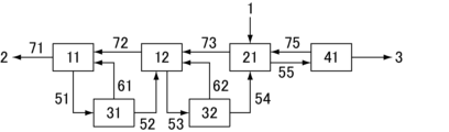
図4は、晶析装置として2つの晶析槽と1つの熟成槽とを有する装置であり、3つの槽の間に1つ上流の槽から直接母液を送液するラインが設置され、最下流の槽から残渣(母液)を直接排出するラインが設置されている。以下に、図1の精製装置と異なる部分のみ説明する。
冷却機構が設置された晶析槽11で冷却され、析出した結晶を含むスラリーはライン51で固液分離装置31に送られる。固液分離装置31ではスラリーが母液と濃縮された結晶スラリーとに分離され、濃縮された結晶スラリーはライン52で隣の晶析槽12に送られ、母液はライン61で晶析槽11に戻される。また、晶析槽11からライン71で精製装置外へ残渣2が排出され、晶析槽11の液面が調整される。晶析槽12においても晶析槽11と同様の操作が行われ、晶析槽12からライン53で結晶を含むスラリーが固液分離装置32に送液される。固液分離装置32ではスラリーが母液と濃縮された結晶スラリーとに分離され、濃縮された結晶スラリーはライン54で隣の熟成槽21に送られ、母液はライン62で晶析槽12に戻される。また晶析槽12の液面調整のため、晶析槽12から晶析槽11へライン72を通して母液が直接送られる。熟成槽21で結晶を成長させた後、結晶スラリーはライン55で機械式洗浄カラム41に送液される。また熟成槽21の液面調整のため、熟成槽21と晶析槽12とをつなぐライン73を通して母液が直接熟成槽21から晶析槽12に送液される。The crystallization apparatus shown in Fig. 4 has two crystallization tanks and one maturation tank, and a line is installed between the three tanks to directly send the mother liquor from the upstream tank, and a line is installed from the most downstream tank to directly discharge the residue (mother liquor). Only the parts that are different from the purification apparatus shown in Fig. 1 will be described below.
The
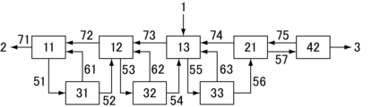
図5は、晶析装置として3つの晶析槽と1つの熟成槽とを有する装置であり、4つの槽の間に1つ上流の槽から直接母液を送液するラインが設置され、最下流の槽から残渣(母液)を直接排出するラインが設置されている。また、洗浄カラムが液圧式であり、結晶ベッドを削り取るための機械的機構を有する。以下に、図4の精製装置と異なる部分のみ説明する。
精製装置に供される化合物の溶液1は晶析槽13に導入される。最下流から2番目の槽である晶析槽12からライン53で結晶を含むスラリーが固液分離装置32に送液される。固液分離装置32ではスラリーが母液と濃縮された結晶スラリーとに分離され、濃縮された結晶スラリーはライン54で隣の晶析槽13に送られ、母液はライン62で晶析槽12に戻される。また晶析槽12の液面調整のため、晶析槽12から晶析槽11へライン72を通して母液が直接送られる。晶析槽13においても晶析槽12と同様の操作が行われ、晶析槽13からライン55で結晶を含むスラリーが固液分離装置33に送液される。固液分離装置33ではスラリーが母液と濃縮された結晶スラリーとに分離され、濃縮された結晶スラリーはライン56で隣の熟成槽21に送られ、母液はライン63で晶析槽13に戻される。また晶析槽13の液面調整のため、晶析槽13から晶析槽12へライン73を通して母液が直接送られる。熟成槽21で結晶を成長させた後、結晶スラリーはライン57で液圧式洗浄カラム42に送液される。また熟成槽21の液面調整のため、熟成槽21と晶析槽13とをつなぐライン74を通して母液が直接熟成槽21から晶析槽13に送液される。
液圧式洗浄カラム42下部では機械的機構(スクレーパー)により結晶ベッドが削り取られ、循環液に懸濁させながら抜き出されて加熱融解され、得られた融解液を含む循環液の一部は高純度の化合物3として搬出される。残りの循環液の一部(洗浄液)は液圧式洗浄カラム42に戻され、結晶ベッドと向流接触させて結晶が洗浄される。Figure 5 shows a crystallization apparatus having three crystallization tanks and one aging tank, with a line between the four tanks that sends the mother liquor directly from the upstream tank, and a line that directly discharges the residue (mother liquor) from the most downstream tank. In addition, the washing column is hydraulic and has a mechanical mechanism for scraping off the crystal bed. Below, only the parts that are different from the purification apparatus in Figure 4 will be explained.
The solution 1 of the compound to be fed to the purification device is introduced into the
At the bottom of the
図6は、晶析装置として2つの晶析槽と1つの熟成槽とを有する装置であり、3つの槽の間に1つ上流の槽から固液分離装置を介して母液を送液するラインが設置され、最下流の槽から固液分離装置を介して残渣を排出するラインが設置されている。以下に、図4の精製装置と異なる部分のみ説明する。
図6の晶析槽11には、直接残渣を排出するラインに代えて、晶析槽内のスラリーから残渣を分離するための固液分離装置33が設置され、晶析槽11から取り出したスラリーがライン81で固液分離装置33に送られ、固液分離装置33で分離された残渣2が精製装置外へ排出され、残りの結晶は晶析槽11に戻され、晶析槽11の液面が調整される。
晶析槽12には、晶析槽11に直接母液を送液するラインに代えて、固液分離装置34が設置され、晶析槽12から取り出したスラリーがライン83で固液分離装置34に送られ、固液分離装置34で分離された母液が液面調整のために晶析槽11へ送られ、残りの結晶は晶析槽12に戻される。
熟成槽21には、晶析槽12に直接母液を送液するラインに代えて、固液分離装置35が設置され、熟成槽21から取り出したスラリーがライン85で固液分離装置35に送られ、固液分離装置35で分離された母液が液面調整のために晶析槽12へ送られ、残りの結晶は熟成槽21に戻される。
洗浄カラム43は液圧式であり、結晶ベッドを削り取るための機械的機構を有さないものである。The crystallization apparatus shown in Fig. 6 has two crystallization tanks and one maturation tank, and a line is provided between the three tanks to send the mother liquor from the upstream tank via a solid-liquid separator, and a line is provided from the most downstream tank to discharge the residue via a solid-liquid separator. Only the parts that are different from the purification apparatus shown in Fig. 4 will be described below.
In the
In place of a line for directly sending mother liquor to the
In place of a line for directly sending the mother liquor to the
The
図7は、晶析装置として2つの晶析槽と1つの熟成槽とを有する装置であり、3つの槽の間に1つ上流の槽から固液分離装置を介して母液を送液するラインが設置され、最下流の槽から固液分離装置を介して残渣を排出するラインが設置されている装置であって、2番目の晶析槽から取り出したスラリーから母液を分離して最下流(1番目)の晶析槽へ送るための固液分離装置、及び、最下流(1番目)の晶析槽から精製装置外に排出する残渣を分離するための固液分離装置を、1つ上流の槽へスラリーを送液するラインに設けられている固液分離装置と共用したものである。以下に、図6の精製装置と異なる部分のみ説明する。
図7の装置では、晶析槽11で冷却され、析出した結晶を含むスラリーはライン51で固液分離装置31に送られる。固液分離装置31ではスラリーが母液と濃縮された結晶スラリーとに分離され、濃縮された結晶スラリーはライン52で隣の晶析槽12に送られる。固液分離装置31で分離された母液のうち一部はライン61で晶析槽11に戻され、残部はライン61に接続された追加ライン101で精製装置外へ排出される。
また晶析槽12で冷却され、析出した結晶を含むスラリーはライン53で固液分離装置32に送られる。固液分離装置32ではスラリーが母液と濃縮された結晶スラリーとに分離され、濃縮された結晶スラリーはライン54で隣の熟成槽21に送られる。固液分離装置32で分離された母液のうち一部はライン62で晶析槽12に戻され、残部はライン62に接続された追加ライン102で晶析槽11に送られる。
図7の精製装置では、ライン51→固液分離装置31→ライン61、101が図6の装置におけるライン81→固液分離装置33→ライン82、91に対応し、固液分離装置33を設置する代わりに、上流の槽へスラリーを送液するラインに設けられている固液分離装置31を共用することで機器点数を減らしている。同様に、ライン53→固液分離装置32→ライン62、102が図6の装置におけるライン83→固液分離装置34→ライン84、92に対応し、固液分離装置34を設置する代わりに、上流の槽へスラリーを送液するラインに設けられている固液分離装置32を共用することで機器点数を減らしている。7 shows a crystallization apparatus having two crystallization tanks and one maturation tank, in which a line is provided between the three tanks for sending the mother liquor from the tank one upstream via a solid-liquid separator, and a line is provided from the most downstream tank for discharging the residue via a solid-liquid separator, in which the solid-liquid separator for separating the mother liquor from the slurry taken out of the second crystallization tank and sending it to the most downstream (first) crystallization tank, and the solid-liquid separator for separating the residue discharged from the most downstream (first) crystallization tank to the outside of the purification apparatus are shared with the solid-liquid separator provided on the line for sending the slurry to the tank one upstream. Only the parts different from the purification apparatus in FIG. 6 will be described below.
In the apparatus of Figure 7, the slurry containing crystals that have been cooled in the
The slurry containing crystals cooled and precipitated in the
In the refining apparatus of Fig. 7,
図8は、晶析装置として2つの晶析槽と1つの熟成槽とを有する装置であり、2番目の晶析槽から最下流(1番目)の晶析槽に固液分離装置を介して母液を送液するラインと、最下流の槽から固液分離装置を介して残渣を排出するラインが設置され、熟成槽から2番目の晶析槽へ直接母液を送液するラインが設置されている装置であって、2番目の晶析槽から取り出したスラリーから母液を分離して最下流の晶析槽へ送るための固液分離装置、及び、最下流の晶析槽から精製装置外に排出する残渣を分離するための固液分離装置を1つ上流の槽へスラリーを送液するラインに設けられている固液分離装置と共用したものである。また、晶析槽として、槽の内容物を槽外で冷却する形式のものを使用している。以下に、図7の精製装置と異なる部分のみ説明する。
図8の装置では、晶析槽11は、槽11Aと槽外の冷却機構11Bとで構成され、ライン111、121で繋がっている。槽11Aからライン111で冷却機構11Bに送られた化合物の溶液(又は化合物の結晶を含むスラリー)は、冷却機構11Bで冷却され、析出した結晶を含むスラリーはライン121で槽11Aに送られる。槽11Aから化合物の結晶を含むスラリーの一部はライン111で冷却機構11Bに送られ、残りはライン51で固液分離装置31に送液される。
晶析槽12も同様に槽12Aと槽外の冷却機構12Bとで構成され、ライン112、122で繋がっている。槽12Aから化合物の結晶を含むスラリーの一部はライン112で冷却機構12Bに送られ、残りはライン53で固液分離装置32に送液される。
図8の装置では、図7の装置の、熟成槽21から固液分離装置35を介して母液を晶析槽12へ送るラインに代えて、熟成槽21から母液を直接槽12Aに送るライン73を有する。Figure 8 shows a crystallization apparatus having two crystallization tanks and one aging tank, in which a line is installed to send the mother liquor from the second crystallization tank to the most downstream (first) crystallization tank via a solid-liquid separator, and a line is installed to discharge the residue from the most downstream tank via a solid-liquid separator, and a line is installed to send the mother liquor directly from the aging tank to the second crystallization tank, and the solid-liquid separator for separating the mother liquor from the slurry taken out of the second crystallization tank and sending it to the most downstream crystallization tank, and the solid-liquid separator for separating the residue discharged from the most downstream crystallization tank to the outside of the purification apparatus are shared with the solid-liquid separator installed on the line sending the slurry to the tank one upstream. In addition, as the crystallization tank, a type in which the contents of the tank are cooled outside the tank is used. Below, only the parts different from the purification apparatus in Figure 7 will be described.
8, the
Similarly, the
The apparatus of FIG. 8 has a
1:化合物の溶液
2:残渣
3:高純度の化合物
11~13:冷却機構を有する晶析槽
11A、12A:槽
11B、12B:冷却機構
21:熟成槽
31~35:固液分離装置
41:機械式洗浄カラム
42:液圧式洗浄カラム(結晶ベッドを削り取るための機械的機構を有するもの)
43:液圧式洗浄カラム(結晶ベッドを削り取るための機械的機構を有さないもの)
51~57:下流の槽から上流の槽又は洗浄カラムへスラリー(又は結晶)を送液するライン
61~63: スラリーから固液分離装置で分離した母液を元の槽へ戻すライン
71:最下流の槽から残渣(母液)を直接精製装置外へ排出するライン
72~74:上流の槽から1つ下流の槽へ母液を直接送液するライン
75:洗浄カラムから母液を晶析装置に返送するライン
81~86:槽から取り出したスラリーから固液分離装置で結晶を分離し、元の槽に戻すライン
91:槽から取り出したスラリーから固液分離装置で分離した残渣(母液)を精製装置外へ排出するライン
92、93:槽から取り出したスラリーから固液分離装置で分離した母液を1つ下流の槽へ送液するライン
101:最下流の槽から取り出したスラリーから固液分離装置で分離した母液の一部を精製装置外へ排出するための追加ライン
102:2番目の槽から取り出したスラリーから固液分離装置で分離した母液の一部を最下流の槽へ送液するための追加ライン
111、121、112、122:槽の内容物を槽外で冷却する形式の晶析槽の槽と冷却機構とをつなぐライン1: Compound solution 2: Residue 3: High-purity compound 11-13: Crystallization tanks with
43: Hydraulic washing column (without mechanical mechanism for scraping off the crystal bed)
51-57: Lines 61-63 for sending slurry (or crystals) from a downstream tank to an upstream tank or washing column;
Claims (9)
該洗浄カラムは、ピストンにて結晶を押し固めて結晶ベッドの形成/搬送を行う機械式洗浄カラム、又は、ポンプにてカラムにスラリーを送液し、カラム内に配置されたフィルターから母液を抜き出すことでベッドの形成/搬送を行う液圧式洗浄カラムのいずれかであり、
該晶析装置はN個(N≧2)の槽を有し、スラリーの流れが向かう方向を上流側として1番目の槽を下流、N番目の槽を上流として直列に接続されており、少なくとも1番目の槽は冷却機構を備えた晶析槽であり、2番目以降の槽は晶析槽または熟成槽であり、
少なくとも1つの槽に化合物を含む被精製液を精製装置外から供給するラインを有し、
該洗浄カラムは、製品を搬出するライン、母液を該晶析装置に返送するラインを有し、該晶析装置に返送するラインは少なくともN番目の槽に接続されており、
該晶析装置は、N番目の槽から該洗浄カラムへスラリーを供給するライン、下流の槽から1つ上流の槽へスラリーを送液するライン、及び、1~N-1番目の各槽に上流の槽から母液を送液するラインを有し、
晶析装置に含まれる1~N-1番目の槽の全てが、固液分離装置を介して1つ上流の槽へスラリーを送液するラインと、該固液分離装置から排出された母液の少なくとも一部を元の槽へと返送するラインとを有し、
下流の槽から上流の槽へスラリーを送液するライン中に設けられている固液分離装置のうち少なくとも1つは、母液を元の槽へ返送するラインに加えて母液を送液する1本以上の追加ラインを有し、該追加ラインは元の槽に対して下流の槽及び/又は精製装置外へ接続されており、
該1~N-1番目の各槽に上流の槽から母液を送液するラインは、1つ上流の槽から母液を直接送液するライン及び1つ上流の槽から固液分離装置を介して母液を送液するラインのいずれか少なくとも1つを含み、
更に精製装置外へ母液を送液するラインを有することを特徴とする精製装置。 A compound purification apparatus comprising a crystallizer having a crystallization section for cooling a compound solution to precipitate crystals , and a washing column for forcibly transporting the compound crystals,
The washing column is either a mechanical washing column in which the crystals are compressed with a piston to form/transport a crystal bed, or a hydraulic washing column in which a slurry is pumped into the column and mother liquor is extracted through a filter disposed in the column to form/transport a bed,
The crystallization apparatus has N tanks (N≧2), which are connected in series with a first tank on the downstream side and an Nth tank on the upstream side in a direction of a slurry flow , at least the first tank being a crystallization tank equipped with a cooling mechanism, and the second and subsequent tanks being crystallization tanks or maturation tanks,
A line is provided for supplying a compound-containing liquid to be purified from outside the purification apparatus to at least one tank,
The wash column has a line for discharging the product and a line for returning the mother liquor to the crystallizer, the line for returning the mother liquor to the crystallizer being connected to at least the Nth tank;
The crystallizer includes a line for supplying a slurry from the Nth tank to the washing column, a line for delivering the slurry from the downstream tank to the tank one upstream, and a line for delivering mother liquor from the upstream tank to each of the 1st to N-1th tanks;
All of the 1st to (N-1th) tanks included in the crystallization apparatus have a line for sending a slurry to the tank one upstream via a solid-liquid separation device, and a line for returning at least a part of the mother liquor discharged from the solid-liquid separation device to the original tank ;
At least one of the solid-liquid separation devices provided in the line for sending the slurry from the downstream tank to the upstream tank has one or more additional lines for sending the mother liquor in addition to a line for returning the mother liquor to the original tank, and the additional lines are connected to the downstream tank and/or the outside of the purification device with respect to the original tank;
the line for sending the mother liquor from an upstream tank to each of the 1st to N-1th tanks includes at least one of a line for directly sending the mother liquor from the tank one upstream and a line for sending the mother liquor from the tank one upstream via a solid-liquid separation device;
The purification apparatus further comprises a line for sending the mother liquor to the outside of the purification apparatus.
該N-1番目の槽からN番目の槽にスラリーを送液するラインに設けられている固液分離装置がバスケット型遠心分離機、またはデカンタ型遠心分離機であることを特徴とする請求項1~8のいずれかに記載の精製装置。 Among the lines for transferring the slurry from the downstream tank to the tank one upstream of the crystallization apparatus, at least the line for transferring the slurry from the (N-1)th tank to the (N)th tank is a line for transferring the slurry to the tank one upstream via a solid-liquid separation apparatus,
The purification apparatus according to any one of claims 1 to 8 , characterized in that a solid-liquid separation device provided in a line for sending the slurry from the (N-1)th tank to the Nth tank is a basket type centrifuge or a decanter type centrifuge.
Applications Claiming Priority (3)
| Application Number | Priority Date | Filing Date | Title |
|---|---|---|---|
| JP2020193566 | 2020-11-20 | ||
| JP2020193566 | 2020-11-20 | ||
| PCT/JP2021/042245 WO2022107812A1 (en) | 2020-11-20 | 2021-11-17 | Purification device |
Publications (2)
| Publication Number | Publication Date |
|---|---|
| JPWO2022107812A1 JPWO2022107812A1 (en) | 2022-05-27 |
| JP7635258B2 true JP7635258B2 (en) | 2025-02-25 |
Family
ID=81708956
Family Applications (1)
| Application Number | Title | Priority Date | Filing Date |
|---|---|---|---|
| JP2022563802A Active JP7635258B2 (en) | 2020-11-20 | 2021-11-17 | Refining Equipment |
Country Status (8)
| Country | Link |
|---|---|
| US (1) | US20240010600A1 (en) |
| EP (1) | EP4249095B1 (en) |
| JP (1) | JP7635258B2 (en) |
| KR (1) | KR102928219B1 (en) |
| CN (1) | CN116457331A (en) |
| TW (1) | TWI891943B (en) |
| WO (1) | WO2022107812A1 (en) |
| ZA (1) | ZA202305911B (en) |
Families Citing this family (2)
| Publication number | Priority date | Publication date | Assignee | Title |
|---|---|---|---|---|
| KR20250028694A (en) | 2023-08-22 | 2025-03-04 | 주식회사 엘지에너지솔루션 | Battery module and battery pack including the same |
| CN117229245B (en) * | 2023-09-18 | 2025-07-04 | 西安国康瑞金制药有限公司 | Purification method of Keli lactone diol |
Citations (5)
| Publication number | Priority date | Publication date | Assignee | Title |
|---|---|---|---|---|
| JP2002114718A (en) | 2000-10-02 | 2002-04-16 | Kobe Steel Ltd | Method for producing 2,6-dimethylnaphthalene |
| JP2002370002A (en) | 2001-04-27 | 2002-12-24 | Korporam Bv | Multistage countercurrent crystallizer |
| JP2004203713A (en) | 2002-12-26 | 2004-07-22 | Mitani Sangyo Co Ltd | Method for producing high-purity aluminum chloride and apparatus for producing high-purity aluminum |
| JP2005232134A (en) | 2004-02-23 | 2005-09-02 | Mitsubishi Chemicals Corp | Method for producing bisphenol A |
| JP2013184948A (en) | 2012-03-09 | 2013-09-19 | Hitachi Ltd | Method of purifying crude aromatic dicarboxylic acid |
Family Cites Families (18)
| Publication number | Priority date | Publication date | Assignee | Title |
|---|---|---|---|---|
| US3872009A (en) | 1971-06-25 | 1975-03-18 | Henricus Alexis Corne Thijssen | Apparatus for the separation and treatment of solid particles from a liquid suspension |
| ZA792809B (en) * | 1978-06-23 | 1980-06-25 | Douwe Egberts Tabaksfab | Continuous packed bed wash column |
| GB2082081B (en) * | 1980-07-24 | 1984-04-26 | Douwe Egberts Tabaksfab | Process for countercurrent crystallization with recirculation |
| NL8200075A (en) * | 1982-01-11 | 1983-08-01 | Tno | METHOD FOR CONTINUALLY PARTIAL CRYSTALIZATION AND SEPARATION OF A LIQUID MIXTURE AND AN APPARATUS FOR CARRYING OUT THIS PROCESS. |
| JPS5966305A (en) | 1982-10-05 | 1984-04-14 | Tsukishima Kikai Co Ltd | Countercurrent melt cooling purification method |
| US4557741A (en) * | 1984-02-13 | 1985-12-10 | Grasso's Koniklyke Machine Fabriekon N.V. | Gradient column freeze concentration system |
| US4787985A (en) * | 1987-08-25 | 1988-11-29 | Grenco Process Technology B.V. | Multi-stage purification unit process |
| GB2262052B (en) * | 1991-12-03 | 1995-07-12 | Shell Int Research | Process for the treatment of a waste water stream |
| JPH0691103A (en) | 1992-09-14 | 1994-04-05 | Tsukishima Kikai Co Ltd | Countercurrent cooling and purifying device for melt and method therefor |
| JP4960562B2 (en) | 2000-04-11 | 2012-06-27 | ビーエーエスエフ ソシエタス・ヨーロピア | Purification of crude acrylic acid melt |
| NL1019862C2 (en) * | 2002-01-30 | 2003-07-31 | Tno | Method and device for processing a suspension. |
| DE102006039203B4 (en) | 2006-08-22 | 2014-06-18 | Evonik Degussa Gmbh | Process for the preparation of crystallization-purified acrylic acid from hydroxypropionic acid and apparatus therefor |
| WO2011001887A1 (en) * | 2009-06-30 | 2011-01-06 | 株式会社日本触媒 | Device for crystallizing acrylic acid and method for crystallizing acrylic acid using same |
| CN201625434U (en) * | 2009-12-30 | 2010-11-10 | 上海奎林化工有限公司 | Purification device |
| EP2471585A1 (en) * | 2011-01-04 | 2012-07-04 | Nederlandse Organisatie voor toegepast- natuurwetenschappelijk onderzoek TNO | Apparatus and method for separating solid particles from a slurry |
| JP2013136523A (en) * | 2011-12-28 | 2013-07-11 | Sumitomo Chemical Co Ltd | METHOD FOR PRODUCING ε-CAPROLACTAM |
| KR102228425B1 (en) * | 2013-01-14 | 2021-03-16 | 술저 매니지멘트 에이지 | Multi-stage crystallisation process and apparatus to purify a compound |
| CN207085389U (en) * | 2017-06-19 | 2018-03-13 | 日益和化工(苏州)有限公司 | A kind of solution crystallization and purification device |
-
2021
- 2021-11-17 CN CN202180077924.XA patent/CN116457331A/en active Pending
- 2021-11-17 JP JP2022563802A patent/JP7635258B2/en active Active
- 2021-11-17 US US18/253,684 patent/US20240010600A1/en active Pending
- 2021-11-17 WO PCT/JP2021/042245 patent/WO2022107812A1/en not_active Ceased
- 2021-11-17 KR KR1020237020173A patent/KR102928219B1/en active Active
- 2021-11-17 EP EP21894686.1A patent/EP4249095B1/en active Active
- 2021-11-19 TW TW110143169A patent/TWI891943B/en active
-
2023
- 2023-06-02 ZA ZA2023/05911A patent/ZA202305911B/en unknown
Patent Citations (5)
| Publication number | Priority date | Publication date | Assignee | Title |
|---|---|---|---|---|
| JP2002114718A (en) | 2000-10-02 | 2002-04-16 | Kobe Steel Ltd | Method for producing 2,6-dimethylnaphthalene |
| JP2002370002A (en) | 2001-04-27 | 2002-12-24 | Korporam Bv | Multistage countercurrent crystallizer |
| JP2004203713A (en) | 2002-12-26 | 2004-07-22 | Mitani Sangyo Co Ltd | Method for producing high-purity aluminum chloride and apparatus for producing high-purity aluminum |
| JP2005232134A (en) | 2004-02-23 | 2005-09-02 | Mitsubishi Chemicals Corp | Method for producing bisphenol A |
| JP2013184948A (en) | 2012-03-09 | 2013-09-19 | Hitachi Ltd | Method of purifying crude aromatic dicarboxylic acid |
Also Published As
| Publication number | Publication date |
|---|---|
| ZA202305911B (en) | 2024-10-30 |
| KR102928219B1 (en) | 2026-02-20 |
| TWI891943B (en) | 2025-08-01 |
| EP4249095A1 (en) | 2023-09-27 |
| WO2022107812A1 (en) | 2022-05-27 |
| EP4249095A4 (en) | 2024-11-20 |
| CN116457331A (en) | 2023-07-18 |
| US20240010600A1 (en) | 2024-01-11 |
| EP4249095B1 (en) | 2026-01-21 |
| KR20230109681A (en) | 2023-07-20 |
| TW202227177A (en) | 2022-07-16 |
| JPWO2022107812A1 (en) | 2022-05-27 |
Similar Documents
| Publication | Publication Date | Title |
|---|---|---|
| KR100382122B1 (en) | Method for producing high purity terephthalic acid | |
| JP7635258B2 (en) | Refining Equipment | |
| CN101385907B (en) | Process for operating a continuous removal of a target product X in the form of fine crystals of the target product X | |
| CN107750181B (en) | Semi-continuous crystallization method and apparatus | |
| JP3731681B2 (en) | Method for producing high purity terephthalic acid | |
| JP7735309B2 (en) | Compound purification method | |
| CN103442777B (en) | For isolating equipment and the method for solid particle from slurry | |
| JP2014503460A (en) | Method for purifying phosphoric acid | |
| JP4188085B2 (en) | Continuous process for producing highly concentrated hydrogen peroxide, highly concentrated hydrogen peroxide and uses thereof | |
| TWI899475B (en) | Tank for purification device, purification device, manufacturing method of compound, and purification method | |
| JP5857730B2 (en) | Centrifuge, method for producing bisphenol A | |
| JP7717803B2 (en) | Method for producing easily polymerizable compound | |
| JP7768984B2 (en) | Method for producing easily polymerizable compound | |
| JP7730364B2 (en) | Purification equipment | |
| JP7804668B2 (en) | Tanks used in refining equipment | |
| JPH0691103A (en) | Countercurrent cooling and purifying device for melt and method therefor | |
| JP2022520198A (en) | Purification method of 4,4'-dichlorodiphenyl sulfoxide | |
| JPH01168648A (en) | Purification of hexamethylenediamine | |
| JPH0794001B2 (en) | Countercurrent melt cooling refining method |
Legal Events
| Date | Code | Title | Description |
|---|---|---|---|
| A621 | Written request for application examination |
Free format text: JAPANESE INTERMEDIATE CODE: A621 Effective date: 20230501 |
|
| A131 | Notification of reasons for refusal |
Free format text: JAPANESE INTERMEDIATE CODE: A131 Effective date: 20240806 |
|
| A521 | Request for written amendment filed |
Free format text: JAPANESE INTERMEDIATE CODE: A523 Effective date: 20241002 |
|
| TRDD | Decision of grant or rejection written | ||
| A01 | Written decision to grant a patent or to grant a registration (utility model) |
Free format text: JAPANESE INTERMEDIATE CODE: A01 Effective date: 20250204 |
|
| A61 | First payment of annual fees (during grant procedure) |
Free format text: JAPANESE INTERMEDIATE CODE: A61 Effective date: 20250212 |
|
| R150 | Certificate of patent or registration of utility model |
Ref document number: 7635258 Country of ref document: JP Free format text: JAPANESE INTERMEDIATE CODE: R150 |