JP7635330B2 - Cleaning Assembly - Google Patents
Cleaning Assembly Download PDFInfo
- Publication number
- JP7635330B2 JP7635330B2 JP2023167874A JP2023167874A JP7635330B2 JP 7635330 B2 JP7635330 B2 JP 7635330B2 JP 2023167874 A JP2023167874 A JP 2023167874A JP 2023167874 A JP2023167874 A JP 2023167874A JP 7635330 B2 JP7635330 B2 JP 7635330B2
- Authority
- JP
- Japan
- Prior art keywords
- cleaning
- cleaning assembly
- cleaning element
- proximal portion
- distal portion
- Prior art date
- Legal status (The legal status is an assumption and is not a legal conclusion. Google has not performed a legal analysis and makes no representation as to the accuracy of the status listed.)
- Active
Links
Images

Classifications
-
- A—HUMAN NECESSITIES
- A24—TOBACCO; CIGARS; CIGARETTES; SIMULATED SMOKING DEVICES; SMOKERS' REQUISITES
- A24F—SMOKERS' REQUISITES; MATCH BOXES; SIMULATED SMOKING DEVICES
- A24F40/00—Electrically operated smoking devices; Component parts thereof; Manufacture thereof; Maintenance or testing thereof; Charging means specially adapted therefor
- A24F40/85—Maintenance, e.g. cleaning
-
- A—HUMAN NECESSITIES
- A24—TOBACCO; CIGARS; CIGARETTES; SIMULATED SMOKING DEVICES; SMOKERS' REQUISITES
- A24F—SMOKERS' REQUISITES; MATCH BOXES; SIMULATED SMOKING DEVICES
- A24F9/00—Accessories for smokers' pipes
- A24F9/04—Cleaning devices for pipes
- A24F9/06—Cleaning devices for pipes for stems, e.g. brushes, needles, strings
-
- A—HUMAN NECESSITIES
- A24—TOBACCO; CIGARS; CIGARETTES; SIMULATED SMOKING DEVICES; SMOKERS' REQUISITES
- A24F—SMOKERS' REQUISITES; MATCH BOXES; SIMULATED SMOKING DEVICES
- A24F9/00—Accessories for smokers' pipes
- A24F9/04—Cleaning devices for pipes
- A24F9/10—Cleaning devices for pipes for bowls, e.g. scrapers, bowl-cleaners with cutting-teeth
Description
本発明は清掃アセンブリ(cleaning assembly)に関し、特に、エアロゾル供給デバイスを清掃するための清掃アセンブリに関する。 The present invention relates to a cleaning assembly, and more particularly to a cleaning assembly for cleaning an aerosol delivery device.
紙巻タバコ、葉巻タバコなどの喫煙品は、使用中にタバコを燃焼させてタバコ煙を発生させる。燃焼させずに化合物を放出する製品を創出することによって、タバコを燃焼させるこれらの喫煙品に代わるものを提供する試みがなされている。そのような製品の例としては、材料を燃焼するのではなく加熱することで化合物を放出する加熱デバイスがある。その材料は、例えば、タバコでもよいし、他の非タバコ製品でもよい。非タバコ製品は、ニコチンを含んでいてもよいし、含んでいなくてもよい。 Smoking articles, such as cigarettes and cigars, burn tobacco to produce tobacco smoke during use. Attempts have been made to provide alternatives to these tobacco-burning smoking articles by creating products that release compounds without combustion. Examples of such products include heating devices that release compounds by heating a material rather than burning it. The material may be, for example, tobacco or other non-tobacco products. The non-tobacco products may or may not contain nicotine.
本発明の第1の態様によれば、エアロゾル供給デバイス用の清掃アセンブリが提供される。本清掃アセンブリは、長手方向軸線を定める軸と、軸の端部に配置された清掃要素とを備える。清掃要素は、近位部、及び近位部と隣り合う遠位部を備える。近位部は、遠位部よりも、軸の長手方向軸線に垂直な方向の断面が大きい。 According to a first aspect of the present invention, there is provided a cleaning assembly for an aerosol delivery device. The cleaning assembly comprises a shaft defining a longitudinal axis and a cleaning element disposed at an end of the shaft. The cleaning element comprises a proximal portion and a distal portion adjacent the proximal portion. The proximal portion has a larger cross-section perpendicular to the longitudinal axis of the shaft than the distal portion.
本発明の第2の態様によれば、エアロゾル供給デバイス用の清掃アセンブリが提供される。本清掃アセンブリは、第1の端部及び第2の端部を有する軸と、軸の第1の端部に配置された第1の清掃要素と、軸の第2の端部に配置された第2の清掃要素とを備える。第1の清掃要素は第2の清掃要素よりも大きい。 According to a second aspect of the present invention, there is provided a cleaning assembly for an aerosol delivery device. The cleaning assembly comprises a shaft having a first end and a second end, a first cleaning element disposed at the first end of the shaft, and a second cleaning element disposed at the second end of the shaft. The first cleaning element is larger than the second cleaning element.
本発明の第3の態様によれば、本発明の第1又は第2の態様による清掃アセンブリと、清掃アセンブリを取り囲む剛性の高い外側ケーシングとを備えるシステムが提供される。 According to a third aspect of the present invention, there is provided a system comprising a cleaning assembly according to the first or second aspect of the present invention and a rigid outer casing surrounding the cleaning assembly.
本発明のさらなる特徴及び利点は、添付の図面を参照して単なる例として挙げる本発明の好ましい実施形態の以下の説明から明らかとなろう。 Further features and advantages of the present invention will become apparent from the following description of preferred embodiments of the invention, given by way of example only with reference to the accompanying drawings.
本開示の例は、エアロゾル供給デバイス用の清掃アセンブリを規定する。使用時に、エアロゾルを供給すると、残留物がエアロゾル供給デバイスの内面に残る結果となることがある。前記残留物の少なくともいくらかを定期的に取り除くことが望ましいことがある。エアロゾル供給デバイスを清掃することが、デバイスの性能を維持する助けになることがある。 An example of the present disclosure provides a cleaning assembly for an aerosol delivery device. During use, dispensing of aerosol may result in residue remaining on the interior surfaces of the aerosol delivery device. It may be desirable to periodically remove at least some of the residue. Cleaning the aerosol delivery device may help maintain the performance of the device.
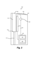
図1は、例示的なエアロゾル供給デバイス100の斜視図である。概略的に述べると、デバイス100は、エアロゾル化可能材料(消耗可能物、又は物品、又は消耗品、又は喫煙材とも呼ばれる)を加熱して、デバイス100の使用者によって吸引されるエアロゾル又は他の吸引可能な媒体を生成するために使用することができる。図1は、エアロゾル化可能材料が中に挿入されていないデバイス100を示す。
Figure 1 is a perspective view of an exemplary
この例のデバイス100は、一端に開口104を有するハウジング102を備える。開口104によって、エアロゾルがデバイス100から出ることができる。いくつかの例では、エアロゾル化可能材料が加熱チャンバに挿入されるとき、開口104はエアロゾル化可能材料を受け入れることができる。しかしながら、他の例では、エアロゾル化可能材料は、別の入口によって加熱チャンバに挿入することができる。例えば、デバイス100の後側のパネル/ドアを開けて、エアロゾル化可能材料を加熱チャンバ内に配置することができる。エアロゾル化可能材料は、タバコでもよいし、他の非タバコ製品でもよく、非タバコ製品は、ニコチン及び/又は香味料を含んでいてもよいし、含んでいなくてもよい。
The
本明細書で使用するとき、用語「香料」及び「香味料」は、成人消費者用の製品において所望の味又は香りを生成するために、現地の規制によって許可される場合に使用することができる材料を指す。いくつかの実施形態では、エアロゾル形成材料は、蒸気又はエアロゾル生成剤又は保湿剤、例えば、グリセロール、プロピレングリコール、トリアセチン、又はジエチレングリコールなどを含んでもよい。 As used herein, the terms "flavor" and "flavoring" refer to materials that may be used, where permitted by local regulations, to produce a desired taste or scent in products for adult consumers. In some embodiments, the aerosol-forming material may include a vapor or aerosol generating agent or humectant, such as glycerol, propylene glycol, triacetin, or diethylene glycol.
この例のデバイス100は、エアロゾル化可能材料が定位置にないときに、開口104を選択的に覆うためにキャップ106を備える。図1では、キャップ106は開いた形態で示されているが、デバイス100が使用されていないときには、キャップ106は閉じた形態にスライドさせることができる。
The
デバイス100は制御要素108をさらに備えてもよい。この例の制御要素108はボタン又はスイッチであり、使用者が制御要素108を作動させると、デバイス100のスイッチが入る。
The
図2は、図1の例示的なデバイス100の断面図である。デバイス100は、エアロゾル化可能材料を受け入れるための加熱チャンバ110を備える。デバイス100は、加熱チャンバ110内に受け入れられたエアロゾル化可能材料を加熱するように配置された1つ又は複数のヒータ120を備える。したがって、エアロゾル化可能材料は、加熱時にヒータ120と相互作用してエアロゾルを生成する。エアロゾル化可能材料は、例えば、エアロゾル化可能材料を受け入れる大きさの加熱チャンバ110内に配置されるように構成された所定又は特定の大きさのものであってもよい。一例では、エアロゾル化可能材料は本質的に管状であり、「タバコスティック(tobacco stick)」として知られていることがある。エアロゾル化可能材料は喫煙材として知られていることもある。
2 is a cross-sectional view of the
デバイス100は、この例では、電子機器132及び電源134を含む電子装置/電力チャンバ130をさらに有する。電子機器132は、エアロゾル化可能材料の加熱を制御するように構成及び配置されたマイクロプロセッサ構成体などのコントローラであってもよい。電子機器132は、制御要素108から信号を受け取り、それに応答してヒータ120を作動させることができる。デバイス100内の電子要素は、破線として示された1つ又は複数のワイヤ136によって電気的に接続されている。
The
デバイス100は、デバイス100の内面にアクセスするための管112を備える。管112は、キャップ(図示せず)によって少なくとも部分的に閉鎖可能であってもよい。管112によって、使用時に、空気は、開口104とは反対側の加熱チャンバ110の端部から加熱チャンバ110に入ることができる。管112は、加熱チャンバ110よりも小さな直径を有し、その結果、加熱チャンバ110と管112との間の境界114は、開口104を通って加熱チャンバ110に挿入されるエアロゾル化可能材料のストッパとして機能する。境界114は、加熱チャンバ110の長手方向軸線に垂直であってもよい。
The
言及したように、使用時に、加熱チャンバ110内のエアロゾル化可能材料は加熱されてエアロゾルを供給する。エアロゾルの生成によって、加熱チャンバ110、管112、及び境界114の内面に残留物が残ることがある。残留物の蓄積の結果、例えば、ヒータ120からエアロゾル化可能材料への熱伝達の低下、使用者にとって不快な味、加熱チャンバ110内でのエアロゾル化可能材料の不正確な配置、及び管112を通って加熱チャンバ110へ供給される空気が不十分であることがもたらされることがある。
As mentioned, during use, the aerosolizable material in the
本開示の態様は、図1及び図2のエアロゾル供給デバイス100などのエアロゾル供給デバイス用の清掃アセンブリを規定する。いくつかの例では、清掃アセンブリは清掃スワブを備えてもよい。
Aspects of the present disclosure provide for a cleaning assembly for an aerosol delivery device, such as the
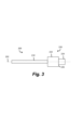
図3は、本開示の第1の例による清掃アセンブリ200の側面図である。清掃アセンブリ200は、長手方向軸線202を定める軸210、及び軸210の端部に配置された清掃要素220を備える。清掃要素220は、近位部222、及び近位部222と隣り合う遠位部224を備える。近位部222は、遠位部224よりも、軸210に垂直な方向の断面が大きい。
3 is a side view of a
この例では、近位部222及び遠位部224は実質的に円柱形で、近位部222は遠位部224よりも大きな直径を有する。他の実施形態では、近位部222及び遠位部224は、円柱形以外、例えば、楕円形及び/又は隆線形であってもよい。清掃要素220は、管の内面、例えば、図2に示した装置100の加熱チャンバ110及び/又は管112の内面を清掃するために管に挿入するためのものである。いくつかの例では、近位部222及び/又は遠位部224は、清掃要素220によって清掃される管の断面形状に対応する断面形状を有してもよい。
In this example, the
図3に示した例では、近位部222と遠位部224は境界面226で接合されている。境界面226は、長手方向軸線202に垂直な平面上にあってもよい。他の例では、境界面226は、清掃アセンブリ200で清掃される異なる直径の2つの管の間の境界に対応する形状を有してもよい。境界面226が2つの管の間の境界と接触するように清掃アセンブリ200が管の1つに挿入されると、清掃要素220は、境界面226によって2つの管の間の境界を清掃することができる。いくつかの例では、境界面226は、遠位部の長手方向軸線に垂直な平面上にあってもよい。
In the example shown in FIG. 3, the
近位部222と遠位部は、長手方向軸線202に沿って互いに隣り合って配置されてもよい。近位部222と遠位部224は隣接していてもよい。近位部222と遠位部224は単一の材料から形成されてもよい。いくつかの例では、近位部22と遠位部224は異なる材料から形成されてもよい。例えば、近位部222と遠位部224は、異なる吸収パラメータ及び/又は異なる硬度を示してもよく、その結果、各部222、224は異なる清掃性能を提供することができる。例えば、近位部222は遠位部224よりも硬く、清掃アセンブリ200で清掃される2つの管の間の境界に対して清掃アセンブリ200の長手方向に加えられた力に抗することができる。
The
いくつかの例では、近位部222の長手方向軸線と遠位部224の長手方向軸線は互いに平行である。例えば、近位部222と遠位部224が平行であるとき、境界面226の平面はまた、近位部222の長手方向軸線に垂直であり得る。いくつかの例では、近位部222及び/又は遠位部224の長手軸方向軸線は長手方向軸線202に平行である。
In some examples, the longitudinal axis of the
近位部222と遠位部224は同軸に配置されてもよく、例えば、図3に示すように、近位部222と遠位部224はそれぞれ、同じ長手方向軸線を有する。このような構成によって、軸210の周りに清掃アセンブリ200を回転させることによって管をより効果的に清掃することができることがある。この構成によってまた、近位部222と遠位部224が同軸でない清掃アセンブリ200に比べて清掃アセンブリ200をより簡単に製造することができる。
The proximal and
近位部222と遠位部224と軸210は同軸に配置されてもよく、例えば、近位部222と遠位部224と軸210はそれぞれ図3に示した長手方向軸線202を有する。このような構成によって、使用時に清掃アセンブリ200をより容易に回転することができる。
The
この例では、清掃要素220は15mmの全長を有する。他の例では、清掃要素220は5mm~30mmの全長を有してもよい。より詳細には、清掃要素は15mm~20mmの全長を有してもよい。清掃要素220の長さは、清掃要素220の材料特性、例えば、吸収力によることがある。
In this example, the
この例では、近位部222は10mmの長さを有する。他の例では、近位部222は4mm~20mmの長さを有してもよい。より詳細には、近位部222は12mm~18mmの長さを有してもよい。近位部222のこの長さは、清掃される管の内面から残留物を取り除くのに十分な表面積を提供することができる。この例では、近位部222は8mmの直径を有する。他の例では、近位部222は2mm~15mmの直径を有してもよい。より詳細には、近位部222は3mm~6mmの直径を有してもよい。近位部222は、清掃アセンブリ200によって清掃されるエアロゾル供給デバイスの大きい方の管の直径、例えば、図2に示した加熱チャンバ110の直径に実質的に等しい直径を有してもよい。
In this example, the
この例では、遠位部224は5mmの長さを有する。他の実施形態では、遠位部224は1mm~10mmの長さを有してもよい。より詳細には、遠位部224は3mm~5mmの長さを有してもよい。遠位部224のこの長さは、清掃される管の内面から残留物を取り除くのに十分な表面積を提供することができる。この例では、遠位部224は4mmの直径を有する。他の実施形態では、遠位部224は1mm~10mmの直径を有してもよい。より詳細には、遠位部224は2mm~5mmの直径を有してもよい。遠位部224は、清掃アセンブリ200によって清掃されるエアロゾル供給デバイスの小さい方の管の直径に実質的に等しい直径を有してもよく、その結果、使用時に近位部222が大きい方の管に十分挿入されたときに、遠位部224は小さい方の管に入ることができる。例えば、遠位部224は、図2に示した管112の直径に実質的に等しい直径を有してもよい。
In this example, the
この例では、近位部222の長さは遠位部224の長さの2倍である。他の例では、近位部222の長さは、遠位部224の長さより2~10倍長くてもよい。より詳細には、近位部222の長さは、遠位部224の長さより3~6倍長くてもよい。
In this example, the length of the
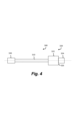
図4は、本開示の第2の例による清掃アセンブリ300の側面図である。清掃アセンブリ300は、図3に示した清掃アセンブリ200と実質的に同じであり、清掃アセンブリ200の開示した特徴のいずれをも有してもよい。対応する特徴は、図4では、対応する参照符号を有するが、それらの参照符号は100を加えられたものである。清掃アセンブリ300は、軸310の清掃要素320とは反対側の端部に配置された第2の清掃要素330をさらに備える。第2の清掃要素330は、清掃要素320によってアクセスできない管を清掃することができることによって、清掃アセンブリ300の機能性を高めることができる。
4 is a side view of a
第2の清掃要素330は実質的に円柱形であってもよい。他の例では、第2の清掃要素330は、円柱形以外の形状、例えば、楕円形又は隆線形であってもよい。第2の清掃要素330の最大直径は、遠位部324の直径に実質的に等しくてもよい。このような構成によって、近位部322の直径よりも小さな直径と、遠位部324が届くことができるところよりも長い長さとを有する管の清掃を可能にすることができる。第2の清掃要素330は、遠位部324と同じ材料から形成されてもよい。
The
この例では、第2の清掃要素は7mmの長さを有する。他の例では、第2の清掃要素330は5mm~25mmの長さを有してもよい。より詳細には、第2の清掃要素330は15mm~20mmの長さを有してもよい。第2の清掃要素330のこの長さは、清掃される管の内面から残留物を取り除くのに十分な表面積を提供することができる。この例では、第2の清掃要素330は4mmの直径を有する。他の例では、第2の清掃要素330は1mm~10mmの直径を有してもよい。より詳細には、第2の清掃要素330は2mm~5mmの直径を有してもよい。第2の清掃要素330は、清掃アセンブリ300によって清掃されるエアロゾル供給デバイスの小さい方の管の直径、例えば、図2に示した管112の直径に実質的に等しい直径を有してもよい。
In this example, the
軸310の直径は第2の清掃要素330の直径よりも小さく、第2の清掃要素330を第2の清掃要素330と実質的に同様の直径の管に挿入することができる。
The diameter of the
清掃要素220、320、330の少なくとも一部に洗浄流体をしみ込ませることができる。例えば、清掃要素220、320、330の少なくとも一部は吸収性があってもよい。洗浄流体は、清掃アセンブリ200、300を使用して清掃される管の内面から残留物を取り除くのに適した任意の流体であってもよい。一例では、清掃要素220、320、330にエタノールをしみ込ませてもよい。洗浄流体をしみ込ませた清掃要素220、320、330で清掃される管に洗浄流体残留物が残されると、清掃後にエアロゾルの香味又は他の特性に影響を及ぼすことがあるが、エタノールは、そのようなことなく、効果的な清掃に有益になることがある。
At least a portion of the
清掃アセンブリ200、300の近位部222、322及び遠位部224、324によって、異なる直径の管を備えるエアロゾル供給デバイスのより効果的及び/又は完全な清掃が可能になる。例えば、近位部222、322及び遠位部224、324の両方によって異なる直径の管を同時に清掃することができる。
The
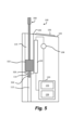
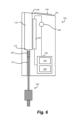
図5は、清掃アセンブリ300が加熱チャンバ110に挿入されている状態の、図1及び図2に示したデバイス100の断面図である。これに代えて、清掃アセンブリ200を加熱チャンバ110に挿入することができることは理解されよう。使用時に、近位部322は加熱チャンバ110の内面に接触し、遠位部324は管112の内面に接触し、したがって、加熱チャンバ110と管112を同時に清掃する。清掃アセンブリ200を、図5に示した清掃アセンブリ200の位置に比べてさらに加熱チャンバ110に挿入すると、境界面326は、加熱チャンバ110と管112との間の境界114に接触することは明らかであろう。これによって、例えば、境界面326と境界114とが接触しているときに清掃アセンブリ200を回転させることによって境界114を清掃することができる。
5 is a cross-sectional view of the
図6は、清掃アセンブリ300が管112に挿入された状態の、図1及び図2に示したデバイス100の断面図である。使用時に、第2の清掃要素320は管112の内面に接触する。遠位部324が管112の長さ全部に届かない場合、使用者は、第2の清掃要素320によって管112の全長に沿って清掃することができることがある。その代わりに、清掃アセンブリ200の遠位部224を遠位部224の長さだけ管112に挿入することができることは理解されよう。いくつかの例では、遠位部224、324は、管112の全長を清掃するのに十分な長さを有してもよい。
6 is a cross-sectional view of the
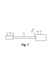
図7は、別の例による清掃アセンブリ400の側面図である。清掃アセンブリ400は、第1の端部412及び第2の端部414を有する軸410を備える。軸410は実質的に円柱形であってもよい。第1の清掃要素420は、軸410の第1の端部412に配置され、第1の実質的な円柱部422を備えてもよい。第2の清掃要素430は、軸410の第2の端部414に配置され、第2の実質的な円柱部432を備えてもよい。この例では、第1の円柱部422は、第2の円柱部432よりも大きな直径を有する。
7 is a side view of a
清掃アセンブリ400は、2つの異なる大きさの空洞を清掃するための単一のアセンブリを提供する。例えば、図1及び図2に示したエアロゾル供給デバイス100を参照すると、第1の円柱部422は、加熱チャンバ110の直径に実質的に等しい直径を有してもよく、第2の円柱部432は、管112の直径に実質的に等しい直径を有してもよい。
The cleaning
この例では、第1の円柱部422は15mmの長さを有する。他の例では、第1の円柱部422は5mm~30mmの長さを有してもよい。より詳細には、第1の円柱部422は15mm~20mmの長さを有してもよい。第1の円柱部422のこの長さは、清掃される管の内面から残留物を取り除くのに十分な表面積を提供することができる。この例では、第1の円柱部は8mmの直径を有する。他の例では、第1の円柱部422は2mm~15mmの直径を有してもよい。より詳細には、第1の円柱部422は3mm~6mmの直径を有してもよい。第1の円柱部422は、清掃アセンブリ400によって清掃されるエアロゾル供給デバイスの大きい方の管の直径、例えば、図2に示した加熱チャンバ110の直径に実質的に等しい直径を有してもよい。
In this example, the first
この例では、第2の円柱部432は10mmの長さを有する。他の例では、第2の円柱部432は5mm~30mmの長さを有してもよい。より詳細には、第2の円柱部432は15mm~20mmの長さを有してもよい。第2の円柱部432のこの長さは、清掃される管の内面から残留物を取り除くのに十分な表面積を提供することができる。この例では、第2の円柱部432は4mmの直径を有する。他の例では、第2の円柱部432は1mm~10mmの直径を有してもよい。より詳細には、第2の円柱部432は2mm~5mmの直径を有してもよい。第2の円柱部432は、清掃アセンブリ400によって清掃されるエアロゾル供給デバイスの小さい方の管の直径、例えば、図2に示した管112の直径に実質的に等しい直径を有してもよい。
In this example, the second
軸410の直径は第2の円柱部432の直径より小さく、第2の円柱部432を第2の円柱部432と実質的に同様の直径の管に挿入することができる。
The diameter of the
第1及び/又は第2の清掃要素420、430に洗浄流体をしみ込ませることができる。例えば、第1及び/又は第2の清掃要素420、430は吸収性があってもよい。洗浄流体は、清掃アセンブリ400を使用して清掃される管の内面から残留物を取り除くのに適した任意の流体であってもよい。一例では、清掃要素420、430にエタノールをしみ込ませてもよい。洗浄流体をしみ込ませた清掃要素420、430で清掃される管に洗浄流体残留物が残されると、清掃後にエアロゾルの香味又は他の特性に影響を及ぼすことがあるが、エタノールは、そのようなことなく、効果的な清掃に有益になることがある。
The first and/or
図7に示した例では、第1及び第2の清掃要素420、430は円柱形である。他の例では、第1及び第2の清掃要素420、430は、例えば、楕円形及び/又は隆線形であってもよい。いくつかの例では、第1及び第2の清掃要素420、430は、それぞれ、第1及び第2の円柱部422、432に加えて他の部分を備えてもよい。これらの他の例では、第1の清掃要素は第2の清掃要素よりも大きい。
In the example shown in FIG. 7, the first and
図3、図4、及び図7に示した例では、清掃アセンブリ200、300、400は90mmの全長を有する。他の例では、清掃アセンブリ200、300、400は50mm~150mmの全長を有してもよい。より詳細には、清掃アセンブリ200、300、400は80mm~110mmの全長を有してもよい。清掃アセンブリ200、300、400の長さは、使用者が、清掃する動きを行うために清掃アセンブリ200、300、400の挿入されていない部分を掴んだまま、清掃される1つ又は複数の管の全長の清掃を可能にするのに十分であることができる。
3, 4, and 7, the cleaning
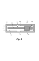
本開示の一例は、図8に示すようなシステム500を提供する。システム500は、本開示の例による清掃アセンブリ、及び清掃アセンブリを取り囲む剛性の高い外側ケーシング510を備える。図8に示した例では、剛性の高い外側ケーシング510は、図3を参照して説明したような清掃アセンブリ200を取り囲む。他の実施形態では、剛性の高い外側ケーシングは、本開示によるいずれかの清掃アセンブリ200、300、400を取り囲んでもよい。
An example of the present disclosure provides a
外側ケーシング510は、使用前の清掃アセンブリ200を保護する。外側ケーシング510は、清掃要素220が使用前に押しつぶされることを防ぐ助けになることができ、その結果、清掃要素220の形状は、管の内面を清掃するように保たれる。外側ケーシング510は、清掃要素220が使用前に異物によって汚されることを防ぐことができ、したがって、清掃アセンブリ200の使用時に望ましくない物質が管の内面に移ることを防ぐことができる。外側ケーシング510は、清掃要素220にしみ込ませた任意の揮発性洗浄流体を保つ助けになることがある。
The
いくつかの例では、剛性の高い外側ケーシング510は、清掃アセンブリ200を部分的に取り囲んでいるだけでもよい。例えば、外側ケーシング510は清掃要素220を取り囲んでもよいが、軸210全部を取り囲まなくてもよく、清掃要素220を取り囲むように軸210の周りにシールを形成してもよい。
In some examples, the rigid
剛性の高い外側ケーシング510は実質的に管状であってもよい。これは、断面が実質的に円形の清掃アセンブリ200を取り囲むために必要な材料の量を減らす助けになることがある。管状ケーシング510は、比較的製造しやすいコンパクトな設計を可能にする。
The rigid
いくつかの例では、剛性の高い外側ケーシング510は一体的に形成され、清掃アセンブリ200にアクセスするためにケーシング510を破断することを容易にするように脆弱部512を備える。図8に示した例では、脆弱部512は、ケーシング510の厚さが薄い部分である。例えば、脆弱部512は、裂け目、溝、ミシン目、又は使用者が、外側ケーシング510に取り囲まれた清掃アセンブリ200にアクセスするのを助ける他の特徴を備えてもよい。
In some examples, the rigid
いくつかの例では、脆弱部512は、清掃アセンブリ200の清掃要素220から離して配置される。このような構成は、ケーシング510を開けたときに清掃要素220に損傷を与えることを避ける助けになり得る。清掃アセンブリが2つ以上の清掃要素を有する場合、脆弱部512は、清掃要素のすべて、又は清掃要素のうちの少なくとも1つから離して配置されてもよい。例えば、図8の例では、脆弱部512は、軸210に沿ってほぼ中間に配置されている。
In some examples, the weakened
いくつかの例では、剛性の高い外側ケーシング510は、清掃アセンブリ200の清掃要素220の半径方向の最大寸法と係合するような大きさの内径Dを有する。図7の例では、ケーシング510の内径Dは、清掃要素220の近位部222と係合するような大きさにされる。このような構成は、ケーシング510全体の大きさを小さくし、清掃アセンブリ200を確実に保持する助けになることがあり、外側ケーシングの内部空洞514内での、清掃要素200にしみ込ませた任意の揮発性洗浄流体の蒸発を減らす助けになることがある。
In some examples, the rigid
この例では、剛性の高い外側ケーシング510は110mmの全長を有する。他の例では、剛性の高い外側ケーシング510は55mm~155mmの全長を有してもよい。より詳細には、剛性の高い外側ケーシング510は85mm~115mmの全長を有してもよい。剛性の高い外側ケーシング510の長さは、取り囲む清掃アセンブリ200、300、400の長さ、及び/又は、ケーシング510の厚さによることがある。
In this example, the rigid
上の実施形態は、本発明の説明のための例として理解されたい。本発明のさらなる実施形態が考えられる。任意の1つの実施形態に関して説明された任意の特徴は、単独で使用されてもよく、又は、説明された他の特徴と組み合わせて使用されてもよく、また、実施形態のうちの任意の他の実施形態の1つ又は複数の特徴と組み合わせて使用されてもよく、又は実施形態のうちの任意の他の実施形態の任意の組合せにおいて使用されてもよいことを理解されたい。さらに、上で説明していない等価物及び修正物もまた、添付の特許請求の範囲に規定される本発明の範囲から逸脱することなく使用することができる。 The above embodiments should be understood as illustrative examples of the present invention. Further embodiments of the present invention are contemplated. It should be understood that any feature described with respect to any one embodiment may be used alone or in combination with other features described, and may also be used in combination with one or more features of any other of the embodiments, or in any combination of any other of the embodiments. Moreover, equivalents and modifications not described above may also be used without departing from the scope of the present invention as defined in the appended claims.
本明細書には以下の条項が記載されている。
[条項1]
長手方向軸線を定める軸と、
前記軸の端部に配置された清掃要素と
を備える、エアロゾル供給デバイス用の清掃アセンブリであって、
前記清掃要素が、近位部、及び前記近位部と隣り合う遠位部を備え、
前記近位部が、前記遠位部よりも、前記軸の前記長手方向軸線に垂直な方向の断面が大きい、清掃アセンブリ。
[条項2]
前記近位部と前記遠位部が同軸に配置されている、条項1に記載の清掃アセンブリ。
[条項3]
前記近位部と前記遠位部と前記軸が同軸に配置されている、条項2に記載の清掃アセンブリ。
[条項4]
前記近位部と前記遠位部が境界面で接合されており、前記境界面が前記長手方向軸線に垂直な平面上にある、条項1~3のいずれか一項に記載の清掃アセンブリ。
[条項5]
前記清掃要素の長さが5mm~30mmである、条項1~4のいずれか一項に記載の清掃アセンブリ。
[条項6]
前記軸の前記清掃要素とは反対側の端部に配置された第2の清掃要素を備える、条項1~5のいずれか一項に記載の清掃アセンブリ。
[条項7]
前記近位部、前記遠位部、及び第2の清掃要素のうちの少なくとも1つが実質的に円柱形である、条項1~6のいずれか一項に記載の清掃アセンブリ。
[条項8]
前記遠位部と前記第2の清掃要素が両方とも実質的に円柱形で、実質的に等しい直径を有する、条項7に記載の清掃アセンブリ。
[条項9]
前記第2の清掃要素の長さが5mm~25mmである、条項6~8のいずれか一項に記載の清掃アセンブリ。
[条項10]
前記近位部の長さが前記遠位部の長さより2~10倍長い、条項1~9のいずれか一項に記載の清掃アセンブリ。
[条項11]
前記近位部の前記長さが4mm~20mmである、条項10に記載の清掃アセンブリ。
[条項12]
前記遠位部の前記長さが1mm~10mmである、条項10に記載の清掃アセンブリ。
[条項13]
第1の端部及び第2の端部を有する軸と、
前記軸の前記第1の端部に配置された第1の清掃要素と、
前記軸の前記第2の端部に配置された第2の清掃要素と
を備え、エアロゾル供給デバイスの清掃アセンブリであって、
前記第1の清掃要素が前記第2の清掃要素よりも大きい、清掃アセンブリ。
[条項14]
前記第1の部分及び前記第2の部分のうちの少なくとも1つの長さが5mm~30mmである、条項13に記載の清掃アセンブリ。
[条項15]
50mm~150mmの全長を有する、条項1~14のいずれか一項に記載の清掃アセンブリ。
The following provisions are included in this specification:
[Clause 1]
a shaft defining a longitudinal axis;
a cleaning element disposed at an end of the shaft,
the cleaning element comprises a proximal portion and a distal portion adjacent the proximal portion;
A cleaning assembly wherein the proximal portion has a larger cross-section perpendicular to the longitudinal axis of the shaft than the distal portion.
[Clause 2]
2. The cleaning assembly of claim 1, wherein the proximal portion and the distal portion are coaxially disposed.
[Clause 3]
3. The cleaning assembly of claim 2, wherein the proximal portion, the distal portion and the shaft are coaxially disposed.
[Clause 4]
4. The cleaning assembly of any one of clauses 1-3, wherein the proximal and distal portions are joined at an interface, the interface lying in a plane perpendicular to the longitudinal axis.
[Clause 5]
5. The cleaning assembly of any one of clauses 1-4, wherein the cleaning element has a length of 5mm to 30mm.
[Clause 6]
6. The cleaning assembly of any one of clauses 1-5, comprising a second cleaning element disposed on an opposite end of the shaft to the cleaning element.
[Clause 7]
7. The cleaning assembly of any one of clauses 1-6, wherein at least one of the proximal portion, the distal portion, and the second cleaning element is substantially cylindrical.
[Clause 8]
8. The cleaning assembly of clause 7, wherein the distal portion and the second cleaning element are both substantially cylindrical and have substantially equal diameters.
[Clause 9]
The cleaning assembly of any one of clauses 6 to 8, wherein the second cleaning element has a length of between 5mm and 25mm.
[Clause 10]
10. The cleaning assembly of any one of clauses 1-9, wherein the length of the proximal portion is 2 to 10 times longer than the length of the distal portion.
[Clause 11]
11. The cleaning assembly of claim 10, wherein the length of the proximal portion is between 4 mm and 20 mm.
[Clause 12]
11. The cleaning assembly of claim 10, wherein the length of the distal portion is between 1 mm and 10 mm.
[Clause 13]
a shaft having a first end and a second end;
a first cleaning element disposed at the first end of the shaft;
a second cleaning element disposed at the second end of the shaft,
A cleaning assembly, wherein the first cleaning element is larger than the second cleaning element.
[Clause 14]
Clause 14. The cleaning assembly of clause 13, wherein at least one of the first portion and the second portion has a length of between 5 mm and 30 mm.
[Clause 15]
15. The cleaning assembly of any one of clauses 1-14, having an overall length of 50mm to 150mm.
Claims (19)
前記軸の端部に配置された清掃要素と
を備える、エアロゾル供給デバイス用の清掃アセンブリであって、
前記清掃要素が、近位部、及び前記近位部と隣り合う遠位部を備え、
前記近位部が、前記遠位部よりも、前記軸の前記長手方向軸線に垂直な方向の断面が大きく、
前記清掃要素の前記近位部及び前記遠位部は、洗浄流体を吸収するための吸収性を有し、前記近位部は、前記遠位部とは異なる程度の吸収性を有する、清掃アセンブリ。 a shaft defining a longitudinal axis;
a cleaning element disposed at an end of the shaft,
the cleaning element comprises a proximal portion and a distal portion adjacent the proximal portion;
the proximal portion has a larger cross-section perpendicular to the longitudinal axis of the shaft than the distal portion;
A cleaning assembly, wherein the proximal and distal portions of the cleaning element have absorbency for absorbing cleaning fluid, the proximal portion having a different degree of absorbency than the distal portion .
エアロゾル供給デバイスと、を備え、
前記近位部及び前記遠位部は、前記エアロゾル供給デバイスの異なる直径の管の内面を清掃するように構成されている、システム。 A cleaning assembly according to any one of claims 1 to 10 ;
an aerosol delivery device,
The system, wherein the proximal portion and the distal portion are configured to clean inner surfaces of tubes of different diameters of the aerosol delivery device.
外側ケーシングと、を備え、
前記外側ケーシングは、前記清掃要素にしみ込んだ揮発性洗浄流体を保つ、システム。 A cleaning assembly according to any one of claims 1 to 10 ;
an outer casing;
The outer casing retains a volatile cleaning fluid impregnated in the cleaning element.
Applications Claiming Priority (4)
| Application Number | Priority Date | Filing Date | Title |
|---|---|---|---|
| GB1906996.2 | 2019-05-17 | ||
| GBGB1906996.2A GB201906996D0 (en) | 2019-05-17 | 2019-05-17 | Cleaning assembly |
| PCT/EP2020/063435 WO2020234101A1 (en) | 2019-05-17 | 2020-05-14 | Cleaning assembly |
| JP2021559843A JP7359862B2 (en) | 2019-05-17 | 2020-05-14 | Cleaning assemblies and systems |
Related Parent Applications (1)
| Application Number | Title | Priority Date | Filing Date |
|---|---|---|---|
| JP2021559843A Division JP7359862B2 (en) | 2019-05-17 | 2020-05-14 | Cleaning assemblies and systems |
Publications (2)
| Publication Number | Publication Date |
|---|---|
| JP2023169407A JP2023169407A (en) | 2023-11-29 |
| JP7635330B2 true JP7635330B2 (en) | 2025-02-25 |
Family
ID=67385086
Family Applications (2)
| Application Number | Title | Priority Date | Filing Date |
|---|---|---|---|
| JP2021559843A Active JP7359862B2 (en) | 2019-05-17 | 2020-05-14 | Cleaning assemblies and systems |
| JP2023167874A Active JP7635330B2 (en) | 2019-05-17 | 2023-09-28 | Cleaning Assembly |
Family Applications Before (1)
| Application Number | Title | Priority Date | Filing Date |
|---|---|---|---|
| JP2021559843A Active JP7359862B2 (en) | 2019-05-17 | 2020-05-14 | Cleaning assemblies and systems |
Country Status (7)
| Country | Link |
|---|---|
| US (1) | US20220202103A1 (en) |
| EP (1) | EP3968792B1 (en) |
| JP (2) | JP7359862B2 (en) |
| KR (1) | KR102806931B1 (en) |
| GB (1) | GB201906996D0 (en) |
| PL (1) | PL3968792T3 (en) |
| WO (1) | WO2020234101A1 (en) |
Families Citing this family (3)
| Publication number | Priority date | Publication date | Assignee | Title |
|---|---|---|---|---|
| KR102676496B1 (en) * | 2022-02-11 | 2024-06-20 | 주식회사 이노아이티 | Aerosol generator with ultrasonic washer |
| KR102973605B1 (en) * | 2022-09-05 | 2026-06-05 | 주식회사 케이티앤지 | Aerosol generating device |
| CN116784534A (en) * | 2023-04-25 | 2023-09-22 | 深圳市赛尔美电子科技有限公司 | Aerosol generating device and cleaning method |
Citations (8)
| Publication number | Priority date | Publication date | Assignee | Title |
|---|---|---|---|---|
| JP3059317U (en) | 1998-11-24 | 1999-07-09 | 憲司 中村 | Injection impregnated packaging containers and their products |
| JP2002529678A (en) | 1998-11-10 | 2002-09-10 | フィリップ・モーリス・プロダクツ・インコーポレイテッド | Brush cleaning unit for heater equipment of smoking equipment |
| JP2011525846A (en) | 2008-06-26 | 2011-09-29 | イーエルシー マネージメント エルエルシー | Single use cosmetic package |
| JP2015033687A (en) | 2013-08-08 | 2015-02-19 | 東都化学工業株式会社 | Cleaning brush for test tube on shaft top of which nonwoven cloth is attached |
| JP2017520236A (en) | 2014-04-30 | 2017-07-27 | フィリップ・モーリス・プロダクツ・ソシエテ・アノニム | Consumables for aerosol generators |
| JP3215374U (en) | 2017-12-27 | 2018-03-15 | 有限会社サプライズ | Cleaning tool for smoking equipment |
| JP3215368U (en) | 2017-12-25 | 2018-03-15 | 有限会社サプライズ | Cleaning tool |
| JP2018082920A (en) | 2016-11-24 | 2018-05-31 | 株式会社カナエ | Package |
Family Cites Families (17)
| Publication number | Priority date | Publication date | Assignee | Title |
|---|---|---|---|---|
| GB179784A (en) * | 1921-04-09 | 1922-05-18 | Fred Jackson | Tobacco pipe cleaner |
| US3856024A (en) * | 1971-06-11 | 1974-12-24 | J Lamberti | Rigid reamer type smoking pipe cleaner |
| JPS55106113A (en) * | 1979-02-09 | 1980-08-14 | Hitachi Ltd | Washing brush |
| DE2933975A1 (en) * | 1979-08-22 | 1981-03-12 | Hans Elstner, Festartikel- Und Chenille-Fabrik, 8867 Oettingen | Pipe smoke passage cleaner - has stem at forward end and larger plunger portion with rear handle |
| DE4304225A1 (en) * | 1992-02-15 | 1993-08-19 | Ulmen Hans Georg | Pipe cleaner with rod with cotton wool ball at each end - has balls of different dia. to suit pipes with different dia. |
| US5632756A (en) * | 1994-12-20 | 1997-05-27 | Kruglick; Kenneth | Ear cleaning device utilizing bulbous banded cage |
| US5970559A (en) * | 1996-03-01 | 1999-10-26 | Christy; Michael | Cleaning tool for cleaning a computer mouse |
| US6045623A (en) * | 1997-04-24 | 2000-04-04 | Cannon; Bradley Jay | Method and apparatus for cleaning catheter lumens |
| JPH114798A (en) * | 1997-06-13 | 1999-01-12 | Shigeru Morishita | Multifunctional cleaning brush |
| JP2000279911A (en) * | 1999-03-30 | 2000-10-10 | Sanritsu Kk | Cotton swab |
| JP4270715B2 (en) * | 2000-05-23 | 2009-06-03 | ピジョン株式会社 | Artificial nipple cleaning tool |
| US20040136770A1 (en) * | 2003-01-09 | 2004-07-15 | Audrey Muhr-Sweeney | Dual cleaning apparatus |
| US8185997B2 (en) * | 2007-11-05 | 2012-05-29 | New Wave Surgical Corporation | Method and apparatus for cleaning the interior cannula of laparoscopic and endoscopic access devices |
| US8551031B2 (en) * | 2011-05-03 | 2013-10-08 | Colson Edme | Swab applicator and methods of use |
| JP6227554B2 (en) * | 2011-12-30 | 2017-11-08 | フィリップ・モーリス・プロダクツ・ソシエテ・アノニム | Smoking article with front plug and aerosol-forming substrate and method thereof |
| US10716327B2 (en) | 2017-05-03 | 2020-07-21 | Robert Thomas Tiefenbacher, Jr. | Portable cleaner with integrated fluid storage compartment and method of using the same |
| CN111818813B (en) * | 2018-03-13 | 2023-07-28 | 菲利普莫里斯生产公司 | Cleaning tools for heating elements |
-
2019
- 2019-05-17 GB GBGB1906996.2A patent/GB201906996D0/en not_active Ceased
-
2020
- 2020-05-14 PL PL20730391.8T patent/PL3968792T3/en unknown
- 2020-05-14 EP EP20730391.8A patent/EP3968792B1/en active Active
- 2020-05-14 US US17/611,065 patent/US20220202103A1/en active Pending
- 2020-05-14 JP JP2021559843A patent/JP7359862B2/en active Active
- 2020-05-14 KR KR1020217037298A patent/KR102806931B1/en active Active
- 2020-05-14 WO PCT/EP2020/063435 patent/WO2020234101A1/en not_active Ceased
-
2023
- 2023-09-28 JP JP2023167874A patent/JP7635330B2/en active Active
Patent Citations (8)
| Publication number | Priority date | Publication date | Assignee | Title |
|---|---|---|---|---|
| JP2002529678A (en) | 1998-11-10 | 2002-09-10 | フィリップ・モーリス・プロダクツ・インコーポレイテッド | Brush cleaning unit for heater equipment of smoking equipment |
| JP3059317U (en) | 1998-11-24 | 1999-07-09 | 憲司 中村 | Injection impregnated packaging containers and their products |
| JP2011525846A (en) | 2008-06-26 | 2011-09-29 | イーエルシー マネージメント エルエルシー | Single use cosmetic package |
| JP2015033687A (en) | 2013-08-08 | 2015-02-19 | 東都化学工業株式会社 | Cleaning brush for test tube on shaft top of which nonwoven cloth is attached |
| JP2017520236A (en) | 2014-04-30 | 2017-07-27 | フィリップ・モーリス・プロダクツ・ソシエテ・アノニム | Consumables for aerosol generators |
| JP2018082920A (en) | 2016-11-24 | 2018-05-31 | 株式会社カナエ | Package |
| JP3215368U (en) | 2017-12-25 | 2018-03-15 | 有限会社サプライズ | Cleaning tool |
| JP3215374U (en) | 2017-12-27 | 2018-03-15 | 有限会社サプライズ | Cleaning tool for smoking equipment |
Also Published As
| Publication number | Publication date |
|---|---|
| GB201906996D0 (en) | 2019-07-03 |
| WO2020234101A1 (en) | 2020-11-26 |
| JP2022532477A (en) | 2022-07-15 |
| EP3968792A1 (en) | 2022-03-23 |
| PL3968792T3 (en) | 2025-12-08 |
| JP2023169407A (en) | 2023-11-29 |
| KR20210151959A (en) | 2021-12-14 |
| KR102806931B1 (en) | 2025-05-12 |
| US20220202103A1 (en) | 2022-06-30 |
| EP3968792B1 (en) | 2025-10-01 |
| JP7359862B2 (en) | 2023-10-11 |
Similar Documents
| Publication | Publication Date | Title |
|---|---|---|
| JP2023169407A (en) | cleaning assembly | |
| AU2017263072B2 (en) | Apparatus for heating smokable material | |
| EP3454681B1 (en) | Apparatus for heating smokable material | |
| KR102592418B1 (en) | Refillable aerosol-generating articles and aerosol-generating kits and systems | |
| ES2744854T3 (en) | Smoking Item with Front Cap and Aerosol Forming Substrate and Method | |
| JP6581597B2 (en) | Consumables for aerosol generators | |
| CN106470563B (en) | Method of preparing an aerosol delivery device | |
| JP6227555B2 (en) | Smoking article with front plug and method thereof | |
| JP7509864B2 (en) | Aerosol Generator | |
| JP7833047B2 (en) | Cleaning tools for cleaning aerosol supply devices | |
| JP2023535875A (en) | Cleaning tool for cleaning the aerosol generator | |
| JP7648777B2 (en) | Non-flammable aerosol delivery device | |
| RU2824931C2 (en) | Cleaning unit | |
| JP7477239B2 (en) | Aerosol-generated products | |
| ES2744707T3 (en) | Circuit for far-field radiation supply of an implantable medical device | |
| KR102533743B1 (en) | Aerosol generating apparatus | |
| KR20210099743A (en) | Tabacco capsule and aerosol generating system using the same | |
| KR20230077746A (en) | Aerosol-generating device with a flexible membrane comprising an opening |
Legal Events
| Date | Code | Title | Description |
|---|---|---|---|
| A621 | Written request for application examination |
Free format text: JAPANESE INTERMEDIATE CODE: A621 Effective date: 20230928 |
|
| A131 | Notification of reasons for refusal |
Free format text: JAPANESE INTERMEDIATE CODE: A131 Effective date: 20241008 |
|
| A521 | Request for written amendment filed |
Free format text: JAPANESE INTERMEDIATE CODE: A523 Effective date: 20250106 |
|
| TRDD | Decision of grant or rejection written | ||
| A01 | Written decision to grant a patent or to grant a registration (utility model) |
Free format text: JAPANESE INTERMEDIATE CODE: A01 Effective date: 20250204 |
|
| A61 | First payment of annual fees (during grant procedure) |
Free format text: JAPANESE INTERMEDIATE CODE: A61 Effective date: 20250212 |
|
| R150 | Certificate of patent or registration of utility model |
Ref document number: 7635330 Country of ref document: JP Free format text: JAPANESE INTERMEDIATE CODE: R150 |