JP7635335B2 - Multi-Component Putters - Google Patents
Multi-Component Putters Download PDFInfo
- Publication number
- JP7635335B2 JP7635335B2 JP2023182319A JP2023182319A JP7635335B2 JP 7635335 B2 JP7635335 B2 JP 7635335B2 JP 2023182319 A JP2023182319 A JP 2023182319A JP 2023182319 A JP2023182319 A JP 2023182319A JP 7635335 B2 JP7635335 B2 JP 7635335B2
- Authority
- JP
- Japan
- Prior art keywords
- putter
- mass
- toe
- heel
- perimeter
- Prior art date
- Legal status (The legal status is an assumption and is not a legal conclusion. Google has not performed a legal analysis and makes no representation as to the accuracy of the status listed.)
- Active
Links
Images


Classifications
-
- A—HUMAN NECESSITIES
- A63—SPORTS; GAMES; AMUSEMENTS
- A63B—APPARATUS FOR PHYSICAL TRAINING, GYMNASTICS, SWIMMING, CLIMBING, OR FENCING; BALL GAMES; TRAINING EQUIPMENT
- A63B53/00—Golf clubs
- A63B53/04—Heads
- A63B53/0416—Heads having an impact surface provided by a face insert
- A63B53/042—Heads having an impact surface provided by a face insert the face insert consisting of a material different from that of the head
- A63B53/0425—Heads having an impact surface provided by a face insert the face insert consisting of a material different from that of the head the face insert comprising two or more different materials
-
- A—HUMAN NECESSITIES
- A63—SPORTS; GAMES; AMUSEMENTS
- A63B—APPARATUS FOR PHYSICAL TRAINING, GYMNASTICS, SWIMMING, CLIMBING, OR FENCING; BALL GAMES; TRAINING EQUIPMENT
- A63B53/00—Golf clubs
- A63B53/04—Heads
- A63B53/0487—Heads for putters
-
- A—HUMAN NECESSITIES
- A63—SPORTS; GAMES; AMUSEMENTS
- A63B—APPARATUS FOR PHYSICAL TRAINING, GYMNASTICS, SWIMMING, CLIMBING, OR FENCING; BALL GAMES; TRAINING EQUIPMENT
- A63B53/00—Golf clubs
- A63B53/04—Heads
- A63B53/06—Heads adjustable
- A63B53/065—Heads adjustable for putters
-
- A—HUMAN NECESSITIES
- A63—SPORTS; GAMES; AMUSEMENTS
- A63B—APPARATUS FOR PHYSICAL TRAINING, GYMNASTICS, SWIMMING, CLIMBING, OR FENCING; BALL GAMES; TRAINING EQUIPMENT
- A63B53/00—Golf clubs
- A63B53/04—Heads
- A63B2053/0491—Heads with added weights, e.g. changeable, replaceable
-
- A—HUMAN NECESSITIES
- A63—SPORTS; GAMES; AMUSEMENTS
- A63B—APPARATUS FOR PHYSICAL TRAINING, GYMNASTICS, SWIMMING, CLIMBING, OR FENCING; BALL GAMES; TRAINING EQUIPMENT
- A63B2209/00—Characteristics of used materials
-
- A—HUMAN NECESSITIES
- A63—SPORTS; GAMES; AMUSEMENTS
- A63B—APPARATUS FOR PHYSICAL TRAINING, GYMNASTICS, SWIMMING, CLIMBING, OR FENCING; BALL GAMES; TRAINING EQUIPMENT
- A63B53/00—Golf clubs
- A63B53/04—Heads
- A63B53/0408—Heads characterised by specific dimensions, e.g. thickness
- A63B53/0412—Volume
-
- A—HUMAN NECESSITIES
- A63—SPORTS; GAMES; AMUSEMENTS
- A63B—APPARATUS FOR PHYSICAL TRAINING, GYMNASTICS, SWIMMING, CLIMBING, OR FENCING; BALL GAMES; TRAINING EQUIPMENT
- A63B53/00—Golf clubs
- A63B53/04—Heads
- A63B53/0416—Heads having an impact surface provided by a face insert
-
- A—HUMAN NECESSITIES
- A63—SPORTS; GAMES; AMUSEMENTS
- A63B—APPARATUS FOR PHYSICAL TRAINING, GYMNASTICS, SWIMMING, CLIMBING, OR FENCING; BALL GAMES; TRAINING EQUIPMENT
- A63B53/00—Golf clubs
- A63B53/04—Heads
- A63B53/0441—Heads with visual indicators for aligning the golf club
Landscapes
- Health & Medical Sciences (AREA)
- General Health & Medical Sciences (AREA)
- Physical Education & Sports Medicine (AREA)
- Golf Clubs (AREA)
Description
本願は、2018年10月1日に出願された米国仮特許No.62/739,747による優先権の利益を主張するものである。その内容はすべて参照により本明細書に完全に組み込まれる。 This application claims the benefit of priority from U.S. Provisional Patent No. 62/739,747, filed October 1, 2018, the entire contents of which are hereby incorporated by reference in their entirety.
本開示は、一般にゴルフクラブに関し、より詳細には、マルチコンポーネントパター型ゴルフクラブヘッドに関する。 This disclosure relates generally to golf clubs, and more particularly to multi-component putter-type golf club heads.
多くのパター型ゴルフクラブヘッドでは、ゴルフクラブヘッドの重心を変化させ、または慣性モーメント(MOI(moment of inertia))を増大させるために、重量分配装置が使用されている。一般的な重量分配装置は、ソールのヒールおよびトウ領域に取り外し可能なウェイトポート、ウェイト付きフェースプレートインサート、フェースの一部の背部のためのインサート、およびトウおよびヒール領域の外周のためのアタッチメントを含む。特に、パター型ゴルフクラブヘッドは、しばしば、ヒールおよびトウ領域におけるウェイトポートを使用する。ウェイトポートは、締結具によって取り外し可能に取り付けられるか、または種々のエポキシ、接着剤、もしくは機械加工方法によって恒久的に取り付けられることができる。ヒールおよびトウ領域にウェイトポートを使用することにより、パターヘッドのMOIが増大し、それにより、インパクト後のボール経路がより真っ直ぐになる。 Many putter-type golf club heads use weight distribution devices to change the center of gravity or increase the moment of inertia (MOI) of the golf club head. Common weight distribution devices include removable weight ports in the heel and toe regions of the sole, weighted face plate inserts, inserts for the back of a portion of the face, and attachments for the perimeter of the toe and heel regions. In particular, putter-type golf club heads often use weight ports in the heel and toe regions. The weight ports can be removably attached by fasteners or permanently attached by various epoxies, adhesives, or machining methods. The use of weight ports in the heel and toe regions increases the MOI of the putter head, which results in a straighter ball path after impact.
ヒールおよびトウ領域におけるこれらのウェイトポートはMOIを増加させるが、それらはゴルフクラブヘッドの重量を増加させ、ゴルフクラブヘッドをパターの理想的な重量よりも重くする。さらに、ウェイトポートをゴルフクラブパターヘッドに取り付けるには、製造中にこれらのウェイトポートをパターヘッドに配置するためのキャビティまたは凹部が必要であり、それによって、そのパターヘッドのコストが増大する。加えて、ウェイトポートは、ゴルフクラブヘッドがゴルフボールに接触したとき、衝撃中にキャビティ内又は凹部内に振動を生じさせることがある。これらのキャビティおよび凹部は、クラブヘッドの音も変化させ、クラブヘッド内に中空の音を作り出す。当技術分野では、ウェイトポートなどの複雑な構造を追加することなく、周囲の重み付けを有し、バランスのとれたパッティングのための理想的なウェイトを有するパターを開発する必要がある。 Although these weight ports in the heel and toe regions increase the MOI, they also increase the weight of the golf club head, making the golf club head heavier than the ideal weight for a putter. Furthermore, attaching weight ports to a golf club putter head requires cavities or recesses in which to place these weight ports in the putter head during manufacturing, thereby increasing the cost of the putter head. In addition, the weight ports can create vibrations within the cavity or recesses during impact when the golf club head contacts the golf ball. These cavities and recesses also change the sound of the club head, creating a hollow sound within the club head. There is a need in the art to develop a putter with perimeter weighting and ideal weight for balanced putting without adding complex structures such as weight ports.
本開示の他の態様は、詳細な説明および添付の図面を考慮することによって明らかになるであろう。 Other aspects of the present disclosure will become apparent by consideration of the detailed description and accompanying drawings.
(I.パターゴルフクラブヘッド) 本明細書では、低密度金属(すなわち、アルミニウムであるが、これに限定されない)などの第1の材料で作られた上部と、高密度金属(すなわち、鋼であるが、これに限定されない)などの第2の材料で作られた下部とを有する2部分パターについて説明する。上部は、打撃フェースからバックエッジまで広がるクラウンを有する。この上部は、下部に固着され、下部よりもグラウンドプレーンから遠い。下部は、ほとんどの実施形態では、パターヘッドのトータル実体積の35%未満であるが、質量の45%を超える。下部は、周辺構造及びソールを提供する。周辺構造と高密度低部とのこの組み合わせは、同じ体積、質量、および単一材料構造(すなわち、鋼パターまたは単一材料のパターインベストメント鋳造などの単一材料のパターミル加工)を有するパターよりも、少なくとも30%のMOIの増加をもたらす。 I. Putter Golf Club Head Described herein is a two-part putter having an upper portion made of a first material, such as a low density metal (i.e., but not limited to, aluminum), and a lower portion made of a second material, such as a high density metal (i.e., but not limited to, steel). The upper portion has a crown that extends from the striking face to the back edge. The upper portion is attached to the lower portion and is further from the ground plane than the lower portion. The lower portion, in most embodiments, is less than 35% of the total actual volume of the putter head, but greater than 45% of the mass. The lower portion provides a perimeter structure and a sole. This combination of perimeter structure and high density lower portion provides an increase in MOI of at least 30% over a putter having the same volume, mass, and single material construction (i.e., a single material putter milled such as a steel putter or a single material putter investment casting).
詳細な説明及び特許請求の範囲の中の「第1の」、「第2の」、「第3の」、及び「第4の」などの用語は、それがある場合には、同様のエレメント同士の間を区別するために使用されており、必ずしも、特定のシーケンシャルな又は時系列の順序を説明するために使用されているわけではない。そのように使用されている用語は、適当な状況下で入れ替え可能であり、本明細書で説明されている実施形態が、例えば、本明細書で図示されているか又はそうでなければ説明されているもの以外のシーケンスの動作が可能であるようになっているということが理解されるべきである。そのうえ、「備える」及び「有する」という用語、ならびに、任意のそれらの変形は、非排他的な包含をカバーすることが意図されており、エレメントのリストを含むプロセス、方法、システム、物品、デバイス、又は、装置が、必ずしもそれらのエレメントに限定されないが、明示的に列挙されていないか、又は、そのようなプロセス、方法、システム、物品、デバイス、もしくは装置に本来備わっている他のエレメントを含むことが可能であるようになっている。 Terms such as "first," "second," "third," and "fourth" in the detailed description and claims, when present, are used to distinguish between similar elements and are not necessarily used to describe a particular sequential or chronological order. It should be understood that such terms are interchangeable under appropriate circumstances, and that the embodiments described herein are capable of, for example, sequences of operation other than those illustrated or otherwise described herein. Moreover, the terms "comprise" and "have," as well as any variations thereof, are intended to cover a non-exclusive inclusion, such that a process, method, system, article, device, or apparatus that includes a list of elements is not necessarily limited to those elements, but may include other elements not expressly listed or inherent in such process, method, system, article, device, or apparatus.
説明および特許請求の範囲における用語「左」、「右」、「前方」、「後方」、「上方」、「下方」、「上方」、「下方」、「上方」、「下方」、「上方」、「下方」などは、説明のために使用され、必ずしも恒久的な相対位置を記述するようには意図されていない。そのように使用される用語は、適切な状況下では相互に交換可能である。従って、本明細書で述べられる装置、方法、及び/又は、製品の実施形態は、例えば、本明細書で示された、または、その他の形で述べられたものとは異なる配向で動作できることを理解されたい。 The terms "left," "right," "front," "rear," "up," "down," "up," "down," "up," "down," "up," "down," and the like in the description and claims are used for explanatory purposes and are not necessarily intended to describe permanent relative positions. Terms so used are interchangeable under appropriate circumstances. Thus, it is to be understood that embodiments of the apparatus, methods, and/or articles of manufacture described herein can operate in orientations other than those shown or otherwise described herein, for example.
本開示の任意の実施形態が詳細に説明される前に、本開示は、その適用において、以下の説明に述べられているような、又は、図面に図示されているような、コンポーネントの詳細又は構築及び配置に限定されないということが理解されるべきである。本開示は、他の実施形態をサポートすることが可能であり、さまざまな方式で実践又は実施され得る。 Before any embodiment of the present disclosure is described in detail, it should be understood that the disclosure is not limited in its application to the details or construction and arrangement of components as set forth in the following description or illustrated in the drawings. The present disclosure is capable of supporting other embodiments and may be practiced or carried out in various ways.
多くの実施形態では、ゴルフクラブヘッドは、パター型ゴルフクラブヘッド(パター型ゴルフクラブヘッド100、200、300、400など)を含むことができる。図1~12Bは、別々に異なる材料で作られ、一緒に結合された上部および下部を有するパター型ゴルフクラブヘッドの複数の実施形態を示す。パター型ゴルフクラブヘッドは、マレット型パターヘッド、ミッドマレット型パターヘッド、ブレード型パターヘッド、高MOIパターヘッド、又は任意の他のタイプのパター型ゴルフクラブヘッドとすることができる。
In many embodiments, the golf club head can include a putter-type golf club head (e.g., putter-type
多くの実施形態では、パター型ゴルフクラブヘッドは、10度未満のロフト角を有することができる。多くの実施形態では、クラブヘッドのロフト角は、0~5度、0~6度、0~7度、または0~8度であり得る。例えば、クラブヘッドのロフト角度は、10°未満、9°未満、8°未満、7°未満、6°未満、または5°未満とすることができる。さらなる例として、クラブヘッドのロフト角は、0度、1度、2度、3度、4度、5度、6度、7度、8度、9度、または10度であり得る。 In many embodiments, the putter-type golf club head can have a loft angle of less than 10 degrees. In many embodiments, the loft angle of the club head can be 0-5 degrees, 0-6 degrees, 0-7 degrees, or 0-8 degrees. For example, the loft angle of the club head can be less than 10°, less than 9°, less than 8°, less than 7°, less than 6°, or less than 5°. As a further example, the loft angle of the club head can be 0 degrees, 1 degree, 2 degrees, 3 degrees, 4 degrees, 5 degrees, 6 degrees, 7 degrees, 8 degrees, 9 degrees, or 10 degrees.
パター型ゴルフクラブヘッドは、上部および下部を含む。ゴルフクラブヘッドは、トウ端部と、トウ端部の反対側のヒール端部とを含むことができる。パター型ゴルフクラブヘッドは、打撃フェースを含むことができる。パター型ゴルフクラブヘッドは、打撃フェースの反対側にリアウォールを備えることができる。さらに、パター型ゴルフクラブヘッドは、アライメント機構を備えることができる。さらに、パター型ゴルフクラブヘッドは、ゴルフクラブヘッドのヒール端に取り付けられたホーゼルを含むことができる。ホーゼルは、パター型ゴルフクラブヘッドの中心に取り付けられてもよい。ホーゼルは、パター型ゴルフクラブヘッドのヒール端部に取り付けることができる。ホーゼルは、パター型ゴルフクラブヘッドの上部と一体的に形成されてもよい。ホーゼルは、パター式ゴルフクラブヘッドの下部と一体に形成することができる。 The putter-type golf club head includes an upper portion and a lower portion. The golf club head may include a toe end and a heel end opposite the toe end. The putter-type golf club head may include a striking face. The putter-type golf club head may include a rear wall opposite the striking face. Additionally, the putter-type golf club head may include an alignment mechanism. Additionally, the putter-type golf club head may include a hosel attached to the heel end of the golf club head. The hosel may be attached to the center of the putter-type golf club head. The hosel may be attached to the heel end of the putter-type golf club head. The hosel may be integrally formed with the upper portion of the putter-type golf club head. The hosel may be integrally formed with the lower portion of the putter-type golf club head.
上部は、第1の材料で作られる。下部は、第2の材料で作られる。第1の材料は、第2の材料とは異なる。第1の材料は、第1の密度を有する。第2の材料は、第2の密度を有する。第1の濃度は、第2の濃度と同じではない。 The top portion is made of a first material. The bottom portion is made of a second material. The first material is different from the second material. The first material has a first density. The second material has a second density. The first density is not the same as the second density.
多くの実施形態では、パター型ゴルフクラブヘッドは、340~385グラムの範囲の質量を有することができる。他の実施形態では、パター型ゴルフクラブヘッドの質量は、340グラム~345グラム、345グラム~350グラム、350グラム~355グラム、355グラム~360グラム、360グラム~365グラム、365グラム~370グラム、370グラム~375グラム、375グラム~380グラム、または380グラム~385グラムの範囲とすることができる。いくつかの実施形態では、パター型ゴルフクラブヘッドの質量は、340グラム、341グラム、342グラム、343グラム、344グラム、345グラム、346グラム、347グラム、348グラム、349グラム、350グラム、351グラム、352グラム、353グラム、354グラム、355グラム、356グラム、357グラム、358グラム、359グラム、360グラム、361グラム、362グラム、363グラム、364グラム、365グラム、366グラム、367グラム、368グラム、369グラム、370グラム、371グラム、372グラム、373グラム、374グラム、375グラム、376グラム、377グラム、378グラム、379グラム、381グラム、382グラム、383グラム、384グラム、とすることができる。 In many embodiments, the putter-type golf club head can have a mass in the range of 340 to 385 grams. In other embodiments, the putter-type golf club head can have a mass in the range of 340 to 345 grams, 345 to 350 grams, 350 to 355 grams, 355 to 360 grams, 360 to 365 grams, 365 to 370 grams, 370 to 375 grams, 375 to 380 grams, or 380 to 385 grams. In some embodiments, the mass of the putter-type golf club head can be 340 grams, 341 grams, 342 grams, 343 grams, 344 grams, 345 grams, 346 grams, 347 grams, 348 grams, 349 grams, 350 grams, 351 grams, 352 grams, 353 grams, 354 grams, 355 grams, 356 grams, 357 grams, 358 grams, 359 grams, 360 grams, 361 grams, 362 grams, 363 grams, 364 grams, 365 grams, 366 grams, 367 grams, 368 grams, 369 grams, 370 grams, 371 grams, 372 grams, 373 grams, 374 grams, 375 grams, 376 grams, 377 grams, 378 grams, 379 grams, 381 grams, 382 grams, 383 grams, and 384 grams.
多くの実施形態では、パター型ゴルフクラブヘッドは、25cc~125ccの範囲のクラブヘッド体積で構成することができる。いくつかの実施形態では、クラブヘッド体積は、25cc~30cc、30cc~35cc、35cc~40cc、40cc~45cc、45cc~50cc、50cc~55cc、55cc~60cc、60cc~65cc、65cc~70cc、70cc~75cc、75cc~80cc、80cc~85cc、85cc~90cc、90cc~95cc、95cc~100cc、100cc~105cc、105cc~110cc、110cc~115cc、115cc~120cc、または120cc~125ccの範囲であり得る。一実施形態では、クラブヘッド体積は、40cc~110ccの範囲とすることができる。いくつかの実施形態では、クラブヘッド体積は、25ccより大きく、50ccより大きく、75ccより大きく、または100ccより大きくてもよい。 In many embodiments, putter-type golf club heads can be configured with club head volumes ranging from 25cc to 125cc. In some embodiments, the club head volume may be in the range of 25cc to 30cc, 30cc to 35cc, 35cc to 40cc, 40cc to 45cc, 45cc to 50cc, 50cc to 55cc, 55cc to 60cc, 60cc to 65cc, 65cc to 70cc, 70cc to 75cc, 75cc to 80cc, 80cc to 85cc, 85cc to 90cc, 90cc to 95cc, 95cc to 100cc, 100cc to 105cc, 105cc to 110cc, 110cc to 115cc, 115cc to 120cc, or 120cc to 125cc. In one embodiment, the club head volume may be in the range of 40cc to 110cc. In some embodiments, the club head volume may be greater than 25 cc, greater than 50 cc, greater than 75 cc, or greater than 100 cc.
いくつかの実施形態では、パター型ゴルフクラブヘッドは、第1の材料で作られた打撃フェースを含むことができる。他の実施形態では、打撃フェースは、第2の材料で作ることができる。これらの実施形態では、打撃フェースの材料は、以下の材料の何れか、またはその組み合わせとすることができる:8620合金鋼(7.83g/cc)、S25C鋼(7.85g/cc)、炭素鋼(7.85g/cc)、マルエージング鋼(8.00g/cc)、17~4ステンレス鋼(7.81g/cc)、303ステンレス鋼(8.03g/cc)、304ステンレス鋼(8.00g/cc)、ステンレス鋼合金(7.75g/cc~8.05g/cc)、タングステン(19.25g/cc)、アルミニウム(2.70g/cc)、アルミニウム合金(2.64g/cc~2.81g/cc)、ADC-12(2.75g/cc)。いくつかの実施形態では、打撃フェースは、上部に一体的に形成することができる。他の実施形態では、打撃フェースは、下部に一体的に形成することができる。打撃フェースは、共成形、射出成形、鋳造、3D造形(additive manufacturing)、または他の成形プロセスによってクラブヘッドに一体的に形成することができる。 In some embodiments, the putter-type golf club head can include a striking face made of a first material. In other embodiments, the striking face can be made of a second material. In these embodiments, the striking face material can be any of the following materials or combinations thereof: 8620 alloy steel (7.83 g/cc), S25C steel (7.85 g/cc), carbon steel (7.85 g/cc), maraging steel (8.00 g/cc), 17-4 stainless steel (7.81 g/cc), 303 stainless steel (8.03 g/cc), 304 stainless steel (8.00 g/cc), stainless steel alloy (7.75 g/cc to 8.05 g/cc), tungsten (19.25 g/cc), aluminum (2.70 g/cc), aluminum alloy (2.64 g/cc to 2.81 g/cc), ADC-12 (2.75 g/cc). In some embodiments, the striking face can be integrally formed on the upper portion. In other embodiments, the striking face can be integrally formed on the lower portion. The striking face can be integrally formed on the club head by co-molding, injection molding, casting, additive manufacturing, or other molding processes.
図11Aおよび11Bを参照すると、いくつかの実施形態では、パター型ゴルフクラブヘッドは、打撃フェースインサートを含むことができる。これらの実施形態では、打撃フェースは、クラブヘッドに結合される前に独立して形成される。クラブヘッドに接触する打撃フェースインサートの側面は、打撃フェースに接触するクラブヘッドの対応する部分のジオメトリに対して、ジオメトリ補完(geometry complementary)を構成することができる。いくつかの実施形態では、打撃フェースインサートは、第1の材料または第2の材料で作ることができる。他の実施形態では、打撃フェースインサートは、第3の材料で作ることができる。いくつかの実施態様において、打撃フェースインサートは、上部又は下部と一体的に形成することができる。他の実施形態では、打撃フェースインサートは、上部および下部の両方から別個に形成することができる。 11A and 11B, in some embodiments, the putter-type golf club head can include a striking face insert. In these embodiments, the striking face is formed separately before being bonded to the club head. The side of the striking face insert that contacts the club head can be geometry complementary to the geometry of the corresponding portion of the club head that contacts the striking face. In some embodiments, the striking face insert can be made of a first material or a second material. In other embodiments, the striking face insert can be made of a third material. In some implementations, the striking face insert can be integrally formed with the upper or lower portion. In other embodiments, the striking face insert can be formed separately from both the upper and lower portions.
打撃フェースは、クラブヘッドの一部に一体的に形成されることによって、または締結手段によってクラブヘッドに固定することができる。いくつかの実施形態では、打撃フェースは上部に固定される。これらの実施形態では、上部は、インサートキャビティを含むことができる。上部インサートキャビティは、打撃フェースインサートを受け入れるように機能する。さらに、これらの実施形態では、インサートが上部に固定されると、上部はインサートキャビティを取り囲み、インサートキャビティと嵌合する。他の実施形態では、打撃フェースは下部に固定される。これらの実施形態では、下部は、インサートキャビティを含むことができる。下部インサートキャビティは、打撃フェースインサートを受け入れるように機能する。さらに、これらの実施形態では、インサートが下部に固定されると、下部はインサートキャビティを包囲し、インサートキャビティと嵌合する。打撃フェースは、接着剤、超高結合(VHB(登録商標))テープ、エポキシ、または別の接着剤などの接着剤によって固定することができる。代替的または追加的に、打撃フェースは、溶接、はんだ付け、ねじ、リベット、ピン、機械的インターロック構造、または別の締結方法によって固定することができる。 The striking face can be secured to the club head by being integrally formed with a portion of the club head or by a fastening means. In some embodiments, the striking face is secured to the upper portion. In these embodiments, the upper portion can include an insert cavity. The upper insert cavity functions to receive the striking face insert. Further, in these embodiments, when the insert is secured to the upper portion, the upper portion surrounds and mates with the insert cavity. In other embodiments, the striking face is secured to the lower portion. In these embodiments, the lower portion can include an insert cavity. The lower insert cavity functions to receive the striking face insert. Further, in these embodiments, when the insert is secured to the lower portion, the lower portion surrounds and mates with the insert cavity. The striking face can be secured by an adhesive, such as a glue, a very high bond (VHB®) tape, an epoxy, or another adhesive. Alternatively or additionally, the striking face can be secured by welding, soldering, screws, rivets, pins, a mechanical interlocking structure, or another fastening method.
これらの実施形態の打撃フェースインサートは、以下の材料の何れか1つ、または、積層組み合わせによって構成することができる:アルミニウム、ステンレス鋼、銅、熱可塑性コポリエステルエラストマー(TPC)、熱可塑性エラストマー(TPE)、熱可塑性ウレタン(TPU)、鋼、ニッケル、TPU/アルミニウム、TPE/アルミニウム、プラスチック/金属スクリーンインサート、ポリエチレン、ポリテトラフルオロエチレン、ポリイソブチレン、ポリ塩化ビニル、PEBAX(登録商標)、またはその他の好ましい材料。PEBAX(登録商標)は、軟質ポリエーテルおよび硬質ポリアミドから作られた熱可塑性エラストマーである、ポリエーテルブロックアミドである。硬質ポリアミドは、ナイロンを含むことができる。PEBAX(登録商標)は、異なるショアD硬度値、ポリエーテルパーセンテージ、および/またはポリアミドパーセンテージに対応する異なる化合物を含むことができる。多くの実施形態では、PEBAX(登録商標)は、PEBAX(登録商標)4033(Arkema, Paris France)またはPEBAX(登録商標)6333(Arkema, Paris France)を含むことができる。PEBAX(登録商標)4033(Arkema, Paris France)は、テトラメチレンオキシド(53重量%)およびナイロン12を含む。PEBAX(登録商標)6333(Arkema, Paris France)は、ナイロン11を含む。いくつかの実施態様において、フェースインサートは、鋼、鋼合金、タングステン、タングステン合金、アルミニウム、アルミニウム合金、チタン、チタン合金、バナジウム、バナジウム合金、クロム、クロム合金、コバルト、コバルト合金、ニッケル、ニッケル合金、他の金属、他の金属合金、複合ポリマー材料又はこれらの任意の組合せなどの材料を含むことができる。 The striking face insert of these embodiments may be constructed of any one or laminate combination of the following materials: aluminum, stainless steel, copper, thermoplastic copolyester elastomer (TPC), thermoplastic elastomer (TPE), thermoplastic urethane (TPU), steel, nickel, TPU/aluminum, TPE/aluminum, plastic/metal screen insert, polyethylene, polytetrafluoroethylene, polyisobutylene, polyvinyl chloride, PEBAX®, or other preferred materials. PEBAX® is a polyether block amide, which is a thermoplastic elastomer made from soft polyethers and hard polyamides. The hard polyamides may include nylon. PEBAX® may include different compounds corresponding to different Shore D hardness values, polyether percentages, and/or polyamide percentages. In many embodiments, PEBAX® may include PEBAX® 4033 (Arkema, Paris France) or PEBAX® 6333 (Arkema, Paris France). PEBAX® 4033 (Arkema, Paris France) contains tetramethylene oxide (53% by weight) and nylon 12. PEBAX® 6333 (Arkema, Paris France) contains nylon 11. In some embodiments, the face insert can include a material such as steel, steel alloy, tungsten, tungsten alloy, aluminum, aluminum alloy, titanium, titanium alloy, vanadium, vanadium alloy, chromium, chromium alloy, cobalt, cobalt alloy, nickel, nickel alloy, other metal, other metal alloy, composite polymer material, or any combination thereof.
PEBAX(登録商標)は、体積パーセンテージのポリエーテルを含むことができる。いくつかの実施形態では、PEBAX(登録商標)は、体積で0%~10%、10%~20%、15%~30%、20%~30%、30%~40%、30%~50%、30%~60%、40%~50%、40%~60%、50%~60%、または60%~70%のポリエーテルを含むことができる。例えば、PEBAX(登録商標)は、0%、5%、10%、15%、20%、25%、30%、35%、40%、45%、50%、55%、60%、65%、または70体積%のポリエーテルを含むことができる。いくつかの実施形態では、PEBAX(登録商標)は、体積で0%~10%、10%~20%、15%~30%、20%~30%、30%~40%、40%~50%、40%~60%、50%~60%、または60%~70%のポリアミドを含むことができる。例えば、PEBAX(登録商標)は、0%、5%、10%、15%、20%、25%、30%、35%、40%、45%、50%、55%、60%、65%、または70体積%のポリアミドを含むことができる。ポリエーテルのパーセンテージが増加するにつれて、PEBAX(登録商標)の硬度は減少する。ポリアミドパーセンテージが増加するにつれて、PEBAX(登録商標)の硬度が増加する。例えば、PEBAX(登録商標)4033(Arkema, Paris France)は、40体積%~60体積%のポリエーテルおよび15体積%~30体積%のポリアミドを含み得る。例えば、PEBAX(登録商標)6333(Arkema, Paris France)は、15容量%~30容量%のポリエーテルおよび40容量%~60容量%のポリアミドを含み得る。 PEBAX® can include a volume percentage of polyether. In some embodiments, PEBAX® can include 0%-10%, 10%-20%, 15%-30%, 20%-30%, 30%-40%, 30%-50%, 30%-60%, 40%-50%, 40%-60%, 50%-60%, or 60%-70% polyether by volume. For example, PEBAX® can include 0%, 5%, 10%, 15%, 20%, 25%, 30%, 35%, 40%, 45%, 50%, 55%, 60%, 65%, or 70% polyether by volume. In some embodiments, PEBAX® can comprise 0%-10%, 10%-20%, 15%-30%, 20%-30%, 30%-40%, 40%-50%, 40%-60%, 50%-60%, or 60%-70% polyamide by volume. For example, PEBAX® can comprise 0%, 5%, 10%, 15%, 20%, 25%, 30%, 35%, 40%, 45%, 50%, 55%, 60%, 65%, or 70% polyamide by volume. As the percentage of polyether increases, the hardness of PEBAX® decreases. As the percentage of polyamide increases, the hardness of PEBAX® increases. For example, PEBAX® 4033 (Arkema, Paris France) may contain 40% to 60% by volume of polyether and 15% to 30% by volume of polyamide. For example, PEBAX® 6333 (Arkema, Paris France) may contain 15% to 30% by volume of polyether and 40% to 60% by volume of polyamide.
多くの実施形態では、PEBAX(登録商標)は、ショア25D~ショア75Dの範囲の硬度を含むことができる。いくつかの実施形態では、PEBAXの硬度は、ショア25D~ショア35D、ショア35D~ショア45D、ショア36D~ショア44D、ショア38D~ショア42D、ショア45D~ショア55D、ショア55D~ショア65D、ショア56D~ショア64D、ショア60D~ショア65D、またはショア65D~ショア75Dの範囲であり得る。例えば、PEBAXの硬度は、ショアD 25、30、35、40、45、50、55、60、65、または70であり得る。 In many embodiments, PEBAX® can include a hardness ranging from Shore 25D to Shore 75D. In some embodiments, the hardness of PEBAX can range from Shore 25D to Shore 35D, Shore 35D to Shore 45D, Shore 36D to Shore 44D, Shore 38D to Shore 42D, Shore 45D to Shore 55D, Shore 55D to Shore 65D, Shore 56D to Shore 64D, Shore 60D to Shore 65D, or Shore 65D to Shore 75D. For example, the hardness of PEBAX can be Shore D 25, 30, 35, 40, 45, 50, 55, 60, 65, or 70.
多くの実施形態では、PEBAX(登録商標)4033(Arkema, Paris France)は、PEBAX(登録商標)6333(Arkema, Paris France)よりも低い硬度を含むことができる。多くの実施形態では、PEBAX(登録商標)4033(Arkema, Paris France)は、ショア35D~ショア55Dの硬度範囲を含むことができる。いくつかの実施形態では、PEBAX(登録商標)4033(Arkema、パリフランス)は、ショア38D~ショア42D、またはショア39D~ショア41Dの硬度範囲を含むことができる。例えば、PEBAX(登録商標)4033(Arkema, Paris France)は、40のショアD硬度を含むことができる。多くの実施形態では、PEBAX(登録商標)6333(Arkema, Paris France)は、ショア50D~ショア75Dの硬度範囲を含むことができる。いくつかの実施形態では、PEBAX(登録商標)6333(Arkema, Paris France)は、ショア55D~ショア70D、またはショア60D~ショア65Dの硬度範囲を含むことができる。例えば、PEBAX(登録商標)6333(Arkema, Paris France)は、63のショアD硬度を含むことができる。 In many embodiments, PEBAX® 4033 (Arkema, Paris France) can include a lower hardness than PEBAX® 6333 (Arkema, Paris France). In many embodiments, PEBAX® 4033 (Arkema, Paris France) can include a hardness range of Shore 35D to Shore 55D. In some embodiments, PEBAX® 4033 (Arkema, Paris France) can include a hardness range of Shore 38D to Shore 42D, or Shore 39D to Shore 41D. For example, PEBAX® 4033 (Arkema, Paris France) can include a Shore D hardness of 40. In many embodiments, PEBAX® 6333 (Arkema, Paris France) can include a hardness range of Shore 50D to Shore 75D. In some embodiments, PEBAX® 6333 (Arkema, Paris France) can include a hardness range of Shore 55D to Shore 70D, or Shore 60D to Shore 65D. For example, PEBAX® 6333 (Arkema, Paris France) can include a Shore D hardness of 63.
いくつかの実施形態では、フェースインサートは、2コンポーネントシステムを含むことができる。2コンポーネントシステムは、ボール打撃フェースプレートとフェースインサートベースとを備えることができる。フェースインサートのボール打撃フェースプレートは、第1のインサート材料を含むことができる。フェースインサートのフェースインサートベースは、第2のインサート材料を含むことができる。多くの実施形態では、ボール打撃フェースプレートの第1のインサート材料とフェースインサートベースの第2の材料とは異なっていてもよい。いくつかの実施形態では、ボール打撃フェースプレートの第1のインサート材料およびフェースインサートベースの第2のインサート材料は、同様であってもよい。多くの実施形態では、ボール打撃フェースプレートの第1のインサート材料は、ポリマータイプの材料を含むことができる。いくつかの実施形態では、ボール打撃フェースプレートの第1のインサート材料は、金属材料を含むことができる。多くの実施形態では、フェースインサートベースの第2のインサート材料は、ポリマータイプの材料を含むことができる。 In some embodiments, the face insert can include a two-component system. The two-component system can include a ball striking face plate and a face insert base. The ball striking face plate of the face insert can include a first insert material. The face insert base of the face insert can include a second insert material. In many embodiments, the first insert material of the ball striking face plate and the second material of the face insert base can be different. In some embodiments, the first insert material of the ball striking face plate and the second insert material of the face insert base can be similar. In many embodiments, the first insert material of the ball striking face plate can include a polymer type material. In some embodiments, the first insert material of the ball striking face plate can include a metallic material. In many embodiments, the second insert material of the face insert base can include a polymer type material.
第1のインサート材料は、鋼、鋼合金、タングステン、タングステン合金、アルミニウム、アルミニウム合金、チタン、チタン合金、バナジウム、バナジウム合金、クロム、クロム合金、コバルト、コバルト合金、ニッケル、ニッケル合金、他の金属、他の金属合金、複合ポリマー材料、またはそれらの任意の組合せなどの金属を含むことができる。 The first insert material can include a metal such as steel, a steel alloy, tungsten, a tungsten alloy, aluminum, an aluminum alloy, titanium, a titanium alloy, vanadium, a vanadium alloy, chromium, a chromium alloy, cobalt, a cobalt alloy, nickel, a nickel alloy, other metals, other metal alloys, composite polymeric materials, or any combination thereof.
第1のインサート材料または第2のインサート材料は、ポリマータイプの材料を含むことができる。ポリマータイプの材料は、ポリエチレン、ポリプロピレン、ポリテトラフルオロエチレン、ポリイソブチレン、ポリ塩化ビニル、または任意の他のポリマータイプの材料を含むことができる。多くの実施形態では、フェースインサートはPEBAX(登録商標)を含むことができる。より具体的には、PEBAX(登録商標)は、可撓性ポリエーテルおよび硬質ポリアミドから作製される熱可塑性エラストマーである、ポリエーテルブロックアミドである。硬質ポリアミドは、ナイロンを含むことができる。PEBAX(登録商標)は、異なるショアD硬度値、ポリエーテルパーセンテージ、および/またはポリアミドパーセンテージに対応する異なる化合物を含むことができる。多くの実施形態では、PEBAX(登録商標)は、PEBAX(登録商標)4033(Arkema, Paris France)またはPEBAX(登録商標)6333(Arkema, Paris France)を含むことができる。PEBAX(登録商標)4033(Arkema, Paris France)は、テトラメチレンオキシド(53重量%)およびナイロン12を含む。PEBAX(登録商標)6333(Arkema, Paris France)は、ナイロン11を含む。第1のインサート材料および第2のインサート材料は、上述したのと同様のポリエーテルパーセンテージ、ポリアミドパーセンテージ、またはショアD硬度値を含むことができる。 The first insert material or the second insert material may include a polymer type material. The polymer type material may include polyethylene, polypropylene, polytetrafluoroethylene, polyisobutylene, polyvinyl chloride, or any other polymer type material. In many embodiments, the face insert may include PEBAX®. More specifically, PEBAX® is a polyether block amide, which is a thermoplastic elastomer made from flexible polyether and hard polyamide. The hard polyamide may include nylon. PEBAX® may include different compounds corresponding to different Shore D hardness values, polyether percentages, and/or polyamide percentages. In many embodiments, PEBAX® may include PEBAX® 4033 (Arkema, Paris France) or PEBAX® 6333 (Arkema, Paris France). PEBAX® 4033 (Arkema, Paris France) contains tetramethylene oxide (53% by weight) and nylon 12. PEBAX® 6333 (Arkema, Paris France) contains nylon 11. The first and second insert materials can contain the same polyether percentages, polyamide percentages, or Shore D hardness values as described above.
前記フェースインサートのボール打撃フェースプレートは、厚さを備えることができる。多くの実施形態では、ボール打撃フェースプレートの厚さは、0.015~0.115インチの範囲とすることができる。いくつかの実施形態では、ボール打撃フェースプレートの厚さは、0.015~0.045インチ、0.020~0.050インチ、0.025~0.055インチ、0.050~0.100インチ、0.055~0.105インチ、0.060~0.110インチ、または0.065~0.115インチの範囲とすることができる。いくつかの実施形態では、ボール打撃フェースプレートの厚さは、少なくとも0.015、0.020、0.025、0.030、0.035、0.040、0.045、0.050、0.055、0.060、0.065、0.070、0.075、0.080、0.085、0.090、0.095、0.10、0.105、0.110、または0.115インチとすることができる。いくつかの実施形態では、ボール打撃フェースプレートの厚さは、0.015、0.020、0.025、0.030、0.035、0.040、0.045、0.050、0.055、0.060、0.065、0.070、0.075、0.080、0.085、0.090、0.095、0.10、0.105、0.110、または0.115インチ以上であり得る。いくつかの実施形態では、ボール打撃フェースプレートの厚さは、0.015、0.020、0.025、0.030、0.035、0.040、0.045、0.050、0.055、0.060、0.065、0.070、0.075、0.080、0.085、0.090、0.095、0.10、0.105、0.110、または0.115インチ以下であり得る。例えば、ボール打撃フェースプレートの厚さは、0.015、0.020、0.025、0.030、0.035、0.040、0.045、0.050、0.055、0.060、0.065、0.070、0.075、0.080、0.085、0.090、0.095、0.10、0.105、0.110、または0.115インチとすることができる。 The ball striking face plate of the face insert may have a thickness. In many embodiments, the thickness of the ball striking face plate may range from 0.015 to 0.115 inches. In some embodiments, the thickness of the ball striking face plate may range from 0.015 to 0.045 inches, 0.020 to 0.050 inches, 0.025 to 0.055 inches, 0.050 to 0.100 inches, 0.055 to 0.105 inches, 0.060 to 0.110 inches, or 0.065 to 0.115 inches. In some embodiments, the ball striking face plate thickness can be at least 0.015, 0.020, 0.025, 0.030, 0.035, 0.040, 0.045, 0.050, 0.055, 0.060, 0.065, 0.070, 0.075, 0.080, 0.085, 0.090, 0.095, 0.10, 0.105, 0.110, or 0.115 inches. In some embodiments, the thickness of the ball striking face plate can be 0.015, 0.020, 0.025, 0.030, 0.035, 0.040, 0.045, 0.050, 0.055, 0.060, 0.065, 0.070, 0.075, 0.080, 0.085, 0.090, 0.095, 0.10, 0.105, 0.110, or 0.115 inches or more. In some embodiments, the thickness of the ball striking face plate can be 0.015, 0.020, 0.025, 0.030, 0.035, 0.040, 0.045, 0.050, 0.055, 0.060, 0.065, 0.070, 0.075, 0.080, 0.085, 0.090, 0.095, 0.10, 0.105, 0.110, or 0.115 inches or less. For example, the thickness of the ball striking face plate can be 0.015, 0.020, 0.025, 0.030, 0.035, 0.040, 0.045, 0.050, 0.055, 0.060, 0.065, 0.070, 0.075, 0.080, 0.085, 0.090, 0.095, 0.10, 0.105, 0.110, or 0.115 inches.
他の実施形態では、ボール打撃フェースプレートの厚さは、0.115~0.40インチの範囲とすることができる。いくつかの実施形態では、ボール打撃フェースプレートの厚さは、0.115~0.20インチ、0.15~0.30インチ、0.20~0.30インチ、0.25~0.35インチ、または0.30~0.40インチの範囲であり得る。いくつかの実施形態では、ボール打撃フェースプレートの厚さは、少なくとも0.15、0.20、0.25、0.30、0.35、または0.40インチとすることができる。いくつかの実施形態では、ボール打撃フェースプレートの厚さは、0.15、0.20、0.25、0.30、0.35、または0.40以上であり得る。いくつかの実施形態では、ボール打撃フェースプレートの厚さは、0.15インチ、0.20インチ、0.25インチ、0.30インチ、0.35インチ、または0.40インチ以下とすることができる。例えば、ボール打撃フェースプレートの厚さは、0.15インチ、0.20インチ、0.25インチ、0.30インチ、0.35インチ、または0.40インチとすることができる。 In other embodiments, the thickness of the ball striking face plate may range from 0.115 to 0.40 inches. In some embodiments, the thickness of the ball striking face plate may range from 0.115 to 0.20 inches, 0.15 to 0.30 inches, 0.20 to 0.30 inches, 0.25 to 0.35 inches, or 0.30 to 0.40 inches. In some embodiments, the thickness of the ball striking face plate may be at least 0.15, 0.20, 0.25, 0.30, 0.35, or 0.40 inches. In some embodiments, the thickness of the ball striking face plate may be 0.15, 0.20, 0.25, 0.30, 0.35, or 0.40 or more. In some embodiments, the thickness of the ball striking face plate may be 0.15 inches, 0.20 inches, 0.25 inches, 0.30 inches, 0.35 inches, or 0.40 inches or less. For example, the thickness of the ball striking face plate can be 0.15 inches, 0.20 inches, 0.25 inches, 0.30 inches, 0.35 inches, or 0.40 inches.
フェースインサートのフェースインサートベースは、厚さを有することができる。多くの実施形態では、フェースインサートベースの厚さは、0.05~0.20インチの範囲とすることができる。いくつかの実施形態では、フェースインサートベースの厚さは、0.05~0.10インチ、または0.10~0.20インチの範囲とすることができる。いくつかの実施形態では、フェースインサートベースの厚さは、少なくとも0.05インチ、0.10インチ、0.15インチ、または0.20インチとすることができる。いくつかの実施形態では、フェースインサートベースの厚さは、0.05インチ、0.10インチ、0.15インチ、または0.20インチ以上とすることができる。いくつかの実施形態では、フェースインサートベースの厚さは、0.05インチ、0.10インチ、0.15インチ、または0.20インチ以下とすることができる。例えば、フェースインサートベースの厚さは、0.05インチ、0.10インチ、0.15インチ、または0.20インチとすることができる。 The face insert base of the face insert can have a thickness. In many embodiments, the thickness of the face insert base can range from 0.05 to 0.20 inches. In some embodiments, the thickness of the face insert base can range from 0.05 to 0.10 inches, or from 0.10 to 0.20 inches. In some embodiments, the thickness of the face insert base can be at least 0.05 inches, 0.10 inches, 0.15 inches, or 0.20 inches. In some embodiments, the thickness of the face insert base can be 0.05 inches, 0.10 inches, 0.15 inches, or 0.20 inches or more. In some embodiments, the thickness of the face insert base can be 0.05 inches, 0.10 inches, 0.15 inches, or 0.20 inches or less. For example, the thickness of the face insert base can be 0.05 inches, 0.10 inches, 0.15 inches, or 0.20 inches.
他の実施形態では、フェースインサートベースの厚さは、0.20~0.80インチの範囲とすることができる。いくつかの実施形態では、フェースインサートベースの厚さは、0.20~0.50インチ、0.30~0.60インチ、0.40~0.70インチ、または0.50~0.80インチの範囲とすることができる。いくつかの実施形態では、フェースインサートベースの厚さは、0.20~0.40インチ、0.30~0.50インチ、0.40~0.60インチ、0.50~0.70インチ、又は0.60~0.80インチの範囲とすることができる。いくつかの実施形態では、フェースインサートのフェースインサートベースは、少なくとも0.20、0.25、0.30、0.35、0.40、0.45、0.50、0.55、0.60、0.65、0.70、0.75、または0.80インチとすることができる。いくつかの実施形態では、フェースインサートのフェースインサートベースは、0.20、0.25、0.30、0.35、0.40、0.45、0.50、0.55、0.60、0.65、0.70、0.75、または0.80インチ以上であり得る。いくつかの実施形態では、フェースインサートのフェースインサートベースは、0.20、0.25、0.30、0.35、0.40、0.45、0.50、0.55、0.60、0.65、0.70、0.75、または0.80インチ以下であり得る。例えば、フェースインサートベースの厚さは、0.20、0.25、0.30、0.35、0.40、0.45、0.50、0.55、0.60、0.65、0.70、0.75、または0.80インチとすることができる。 In other embodiments, the thickness of the face insert base can range from 0.20 to 0.80 inches. In some embodiments, the thickness of the face insert base can range from 0.20 to 0.50 inches, 0.30 to 0.60 inches, 0.40 to 0.70 inches, or 0.50 to 0.80 inches. In some embodiments, the thickness of the face insert base can range from 0.20 to 0.40 inches, 0.30 to 0.50 inches, 0.40 to 0.60 inches, 0.50 to 0.70 inches, or 0.60 to 0.80 inches. In some embodiments, the face insert base of the face insert can be at least 0.20, 0.25, 0.30, 0.35, 0.40, 0.45, 0.50, 0.55, 0.60, 0.65, 0.70, 0.75, or 0.80 inches. In some embodiments, the face insert base of the face insert can be 0.20, 0.25, 0.30, 0.35, 0.40, 0.45, 0.50, 0.55, 0.60, 0.65, 0.70, 0.75, or 0.80 inches or more. In some embodiments, the face insert base of the face insert can be 0.20, 0.25, 0.30, 0.35, 0.40, 0.45, 0.50, 0.55, 0.60, 0.65, 0.70, 0.75, or 0.80 inches or less. For example, the thickness of the face insert base can be 0.20, 0.25, 0.30, 0.35, 0.40, 0.45, 0.50, 0.55, 0.60, 0.65, 0.70, 0.75, or 0.80 inches.
フェースインサートは、多くの異なるプロセスによって形成することができる。異なる成形プロセスは、射出成形、鋳造、ブロー成形、圧縮成形、共成形、レーザー成形、フィルムインサート成形、ガスアシスト成形、回転成形、熱成形、レーザー切断、3-D印刷、鍛造、スタンピング、電鋳、機械加工、成形、またはそれらの任意の組み合わせを含む。さらに、フェースインサートは、上述の硬度、体積、厚さ、および成形プロセスの任意の組み合わせを有することができる。 The face insert can be formed by many different processes. The different molding processes include injection molding, casting, blow molding, compression molding, co-molding, laser molding, film insert molding, gas-assisted molding, rotational molding, thermoforming, laser cutting, 3-D printing, forging, stamping, electroforming, machining, molding, or any combination thereof. Additionally, the face insert can have any combination of the hardness, volume, thickness, and molding process described above.
多くの実施形態では、第1の材料を有するパター型ゴルフクラブヘッドの上部は、1.0g/cc~6.0g/ccの範囲の第1の密度を含む。第1の密度は、2.0g/cc~5.0g/ccの範囲であり得る。いくつかの実施形態では、第1の密度は、1.0~1.25g/cc、1.25~1.5g/cc、1.5~1.75g/cc、1.75~2.75g/cc、2.0~2.25g/cc、2.25~2.5g/cc、2.5~2.75g/cc、2.75~3.75g/cc、3.25~3.5g/cc、3.5~3.75g/cc、3.75~4.0g/cc、4.0~4.25g/cc、4.5~4.75g/cc、4.75~5.0g/cc、5.0~5.25g/cc -5.5g/cc、5.5~5.75g/cc、または5.75~6.0g/ccの範囲であり得る。一実施形態では、下部の第1の密度は、2.0~3.0g/ccの範囲とすることができる。いくつかの実施形態では、第1の密度は、6.0g/cc未満、5.0g/cc未満、4.0g/cc未満、3.0g/cc未満、または2.0g/cc未満であり得る。いくつかの実施形態では、第1の密度は、1.25g/cc、1.50g/cc、1.75g/cc、2.0g/cc、2.25g/cc、2.50g/cc、2.75g/cc、3.0g/cc、3.25g/cc、3.50g/cc、3.75g/cc、4.0g/cc、4.25g/cc、4.50g/cc、4.75g/cc、5.0g/cc、5.25g/cc、5.50g/cc、5.75g/cc、6.0g/cc、であり得る。 In many embodiments, the upper portion of the putter-type golf club head having the first material includes a first density in the range of 1.0 g/cc to 6.0 g/cc. The first density can be in the range of 2.0 g/cc to 5.0 g/cc. In some embodiments, the first density can be in the range of 1.0 to 1.25 g/cc, 1.25 to 1.5 g/cc, 1.5 to 1.75 g/cc, 1.75 to 2.75 g/cc, 2.0 to 2.25 g/cc, 2.25 to 2.5 g/cc, 2.5 to 2.75 g/cc, 2.75 to 3.75 g/cc, 3.25 to 3.5 g/cc, 3.5 to 3.75 g/cc, 3.75 to 4.0 g/cc, 4.0 to 4.25 g/cc, 4.5 to 4.75 g/cc, 4.75 to 5.0 g/cc, 5.0 to 5.25 g/cc -5.5 g/cc, 5.5 to 5.75 g/cc, or 5.75 to 6.0 g/cc. In one embodiment, the first density of the lower portion can be in the range of 2.0 to 3.0 g/cc, hi some embodiments, the first density can be less than 6.0 g/cc, less than 5.0 g/cc, less than 4.0 g/cc, less than 3.0 g/cc, or less than 2.0 g/cc. In some embodiments, the first density can be 1.25 g/cc, 1.50 g/cc, 1.75 g/cc, 2.0 g/cc, 2.25 g/cc, 2.50 g/cc, 2.75 g/cc, 3.0 g/cc, 3.25 g/cc, 3.50 g/cc, 3.75 g/cc, 4.0 g/cc, 4.25 g/cc, 4.50 g/cc, 4.75 g/cc, 5.0 g/cc, 5.25 g/cc, 5.50 g/cc, 5.75 g/cc, 6.0 g/cc.
多くの実施形態では、パター型ゴルフクラブヘッドの下部は、第2の材料を有する。第2の材料は、密度を含むことができる。密度は、上部における第1の材料の第1の密度に対する第2の密度である。下部の第2の材料の第2の密度は、7.0g/cc~20.0g/ccの範囲とすることができる。いくつかの実施形態では、第2の密度は、7.0~7.5g/cc、7.5~8.0g/cc、8.0~8.5g/cc、8.5~9.0g/cc、9.0~9.5g/cc、9.5~10.0g/cc、10.0~10.5g/cc、10.5~11.0g/cc、11.0~11.5g/cc、11.512.0g/cc、12.0~12.5g/cc、12.5~13.0g/cc、13.0~13.5g/cc、13.5~14.0g/cc、14.0~14.5g/cc、14.5~15.0 0g/cc、16.0~16.5g/cc、16.5~17.0g/cc、17.0~17.5g/cc、17.5~18.0g/cc、18.0~18.5g/cc、18.5~19.0g/cc、または19.0~19.5g/cc、または19.5~20.0g/ccの範囲とすることができる。一実施形態では、下部における第2の材料の第2の密度は、8.0~9.0g/ccの範囲とすることができる。いくつかの実施形態では、第2の密度は、7.0g/cc、7.5g/cc、8.0g/cc、8.5g/cc、9.0g/cc、9.5g/cc、10.0g/cc、10.5g/cc、11.0g/cc、11.5g/cc、12.0g/cc、12.5g/cc、13.0g/cc、13.5g/cc、14.0g/cc、14.5g/cc、15.0g/cc、15.5g/cc、16.0g/cc、16.5g/cc、17.0g/cc、17.5g/cc、18.0g/cc、18.5g/cc、19.0g/cc、19.5g/cc、20.0g/cc、とすることができる。いくつかの実施形態では、下部の第2の密度は、第1の密度の少なくとも2倍、第1の密度の少なくとも3倍、第1の密度の少なくとも4倍、または第1の密度の少なくとも5倍であり得る。いくつかの実施形態では、第2の密度は、7.0g/ccを超え、9.0g/ccを超え、10.0g/ccを超え、11.0g/ccを超え、または12.0g/ccを超えることができる。 In many embodiments, the lower portion of the putter-type golf club head has a second material. The second material can include a density. The density is a second density relative to the first density of the first material in the upper portion. The second density of the second material in the lower portion can range from 7.0 g/cc to 20.0 g/cc. In some embodiments, the second density is 7.0 to 7.5 g/cc, 7.5 to 8.0 g/cc, 8.0 to 8.5 g/cc, 8.5 to 9.0 g/cc, 9.0 to 9.5 g/cc, 9.5 to 10.0 g/cc, 10.0 to 10.5 g/cc, 10.5 to 11.0 g/cc, 11.0 to 11.5 g/cc, 11.5 to 12.0 g/cc, 12.0 to 12.5 g/cc, 12.5 to 13.0 g/cc, 13.0 to 13.5 g/cc, 13.5 to 14.0 g/cc, 14.0 to 14.5 g/cc, 14.5 to 15.0 g/cc, 15.0 to 16.0 g/cc, 16.0 to 17.0 g/cc, 17.0 to 18.0 g/cc, 18.0 to 19.0 g/cc, 19.0 to 20.0 g/cc, 20.0 to 21.0 g/cc, 20.0 to 22.0 g/cc, 20.0 to 23.0 g/cc, 20.0 to 24.0 g/cc, 20.0 to 25.0 g/cc, 20.0 to 26.0 g/cc, 20.0 to 27.0 g/cc, 20.0 to 28.0 g/cc, 20.0 to 29.0 g/cc, 20.0 to 30.0 g/cc, 20.0 to 31.0 g/cc, 20.0 to 32.0 g/cc, 20.0 to 33.0 g/cc, 20. 0 g/cc, 16.0-16.5 g/cc, 16.5-17.0 g/cc, 17.0-17.5 g/cc, 17.5-18.0 g/cc, 18.0-18.5 g/cc, 18.5-19.0 g/cc, or 19.0-19.5 g/cc, or 19.5-20.0 g/cc. In one embodiment, the second density of the second material in the lower portion can be in the range of 8.0-9.0 g/cc. In some embodiments, the second density is 7.0 g/cc, 7.5 g/cc, 8.0 g/cc, 8.5 g/cc, 9.0 g/cc, 9.5 g/cc, 10.0 g/cc, 10.5 g/cc, 11.0 g/cc, 11.5 g/cc, 12.0 g/cc, 12.5 g/cc, 13.0 g/cc, 13. 5 g/cc, 14.0 g/cc, 14.5 g/cc, 15.0 g/cc, 15.5 g/cc, 16.0 g/cc, 16.5 g/cc, 17.0 g/cc, 17.5 g/cc, 18.0 g/cc, 18.5 g/cc, 19.0 g/cc, 19.5 g/cc, 20.0 g/cc. In some embodiments, the second density of the lower portion can be at least twice the first density, at least three times the first density, at least four times the first density, or at least five times the first density. In some embodiments, the second density can be greater than 7.0 g/cc, greater than 9.0 g/cc, greater than 10.0 g/cc, greater than 11.0 g/cc, or greater than 12.0 g/cc.
第1の材料を有するパター型ゴルフクラブの上部は、以下のいずれかまたは組み合わせから作製され得る:8620合金鋼(7.83g/cc)、S25C鋼(7.85g/cc)、炭素鋼(7.85g/cc)、マルエージング鋼(8.00g/cc)、17-4ステンレス鋼(7.81g/cc)、303ステンレス鋼(8.03g/cc)、304ステンレス鋼(8.00g/cc)、ステンレス鋼合金(7.75g/cc-8.05g/cc)、タングステン(19.25g/cc)、アルミニウム(2.70g/cc)、アルミニウム合金(2.64g/cc-2.81g/cc)、ADC-12(2.75g/cc)、またはゴルフクラブヘッドを作製するために適した他の金属。多くの実施形態において、上部は、アルミニウム合金又はADC-12からなる。 The upper portion of the putter-type golf club having the first material may be made from any of the following or a combination: 8620 alloy steel (7.83 g/cc), S25C steel (7.85 g/cc), carbon steel (7.85 g/cc), maraging steel (8.00 g/cc), 17-4 stainless steel (7.81 g/cc), 303 stainless steel (8.03 g/cc), 304 stainless steel (8.00 g/cc), stainless steel alloy (7.75 g/cc-8.05 g/cc), tungsten (19.25 g/cc), aluminum (2.70 g/cc), aluminum alloy (2.64 g/cc-2.81 g/cc), ADC-12 (2.75 g/cc), or other metals suitable for making golf club heads. In many embodiments, the upper portion is made of aluminum alloy or ADC-12.
第2の材料を有するパター型ゴルフクラブの下部は、以下のいずれかまたは組み合わせから作製され得る:8620合金鋼(7.83g/cc)、S25C鋼(7.85g/cc)、炭素鋼(7.85g/cc)、マルエージング鋼(8.00g/cc)、17~4ステンレス鋼(7.81g/cc)、303ステンレス鋼(8.03g/cc)、304ステンレス鋼(8.00g/cc)、ステンレス鋼合金(7.75g/cc~8.05g/cc)、タングステン(19.25g/cc)、アルミニウム(2.70g/cc)、アルミニウム合金(2.64g/cc~2.81g/cc)、ADC-12(2.75g/cc)、またはゴルフクラブヘッドを作製するために適した他の金属。多くの実施形態において、下部は、304ステンレス鋼、8620合金鋼、17-4ステンレス鋼、または1380ステンレス鋼で作られる。しかしながら、下部および上部は、同じ1つの材料または同じ材料の組み合わせから作られていない。 The lower portion of the putter-type golf club having the second material may be made from any or combination of the following: 8620 alloy steel (7.83 g/cc), S25C steel (7.85 g/cc), carbon steel (7.85 g/cc), maraging steel (8.00 g/cc), 17-4 stainless steel (7.81 g/cc), 303 stainless steel (8.03 g/cc), 304 stainless steel (8.00 g/cc), stainless steel alloy (7.75 g/cc to 8.05 g/cc), tungsten (19.25 g/cc), aluminum (2.70 g/cc), aluminum alloy (2.64 g/cc to 2.81 g/cc), ADC-12 (2.75 g/cc), or other metals suitable for making golf club heads. In many embodiments, the lower portion is made of 304 stainless steel, 8620 alloy steel, 17-4 stainless steel, or 1380 stainless steel. However, the lower portion and upper portion are not made of the same material or combination of materials.
さらに、パター型ゴルフクラブヘッドの上部および下部は、溶接、はんだ付け、ろう付け、かしめ(swedging)、接着、エポキシ、または機械的締結のいずれかの方法または組み合わせで接合することができる。いくつかの実施形態では、上部および下部は、エポキシ、ポリウレタン、樹脂、ホットメルト、または任意の他の接着剤との接着によって接合することができる。 In addition, the upper and lower portions of the putter-type golf club head may be joined by any method or combination of welding, soldering, brazing, swedging, adhesives, epoxies, or mechanical fastening. In some embodiments, the upper and lower portions may be joined by adhesion with epoxy, polyurethane, resin, hot melt, or any other adhesive.
(A.利点) パター型ゴルフクラブヘッドは、異なる密度を有する上部および下部、および/または、機械的に固定されたウェイトまたはウェイトポートを使用しない上部および下部を有するパター型ゴルフクラブヘッドにおいて、MOI、CG、フィーリング、およびウェイティングの利点を提供する。2つの異なる材料からパター型ゴルフクラブヘッドの上部および下部を作り出すことによって、パター型ゴルフクラブヘッドのヒール端部およびトウ端部へのウェイトポートまたはアタッチメントなしに、クラブヘッドの重量は、パター型ゴルフクラブヘッドの周辺に向かってシフトする。この重量のパター型ゴルフクラブヘッドの周辺部に向かうシフトは、クラブヘッドのMOIをy軸(Iyy)について上昇させる。したがって、y軸の周りの回転を防止し、打撃フェースがインパクト中にゴルフボールに対してスクエアであることを保証する。y軸周りのMOIの増加は、より真っ直ぐなボール経路を達成し、中心から外れた打撃(ヒール端部またはトウ端部での衝撃)の結果を改善するのに役立つ。 (A. Advantages) The putter-type golf club head provides MOI, CG, feel, and weighting advantages in a putter-type golf club head with upper and lower parts having different densities and/or upper and lower parts without the use of mechanically fixed weights or weight ports. By creating the upper and lower parts of the putter-type golf club head from two different materials, the weight of the club head is shifted toward the periphery of the putter-type golf club head without weight ports or attachments to the heel and toe ends of the putter-type golf club head. This shift of weight toward the periphery of the putter-type golf club head raises the MOI of the club head about the y-axis (Iyy), thus preventing rotation about the y-axis and ensuring that the striking face is square to the golf ball during impact. The increase in MOI about the y-axis helps achieve a straighter ball path and improves the outcome of off-center hits (impacts at the heel or toe ends).
2つの異なる材料の2つの部分からパター型ゴルフクラブヘッドを作り出すことによって、パター型ゴルフクラブヘッドは、ゴルフクラブヘッドを所望の総重量に保ちながら、MOIを改善するように最適化することができる。いくつかの実施態様において、y軸重心を中心とするゴルフクラブヘッドの慣性モーメントは、3500g・cm2-6500g・in2の間である。他の実施形態では、y軸重心の周りのゴルフクラブヘッドの慣性モーメントは、3500g・cm2-4000g・cm2、4000g・cm2-4500g・cm2、4500g・cm2-5000g・cm2、5000g・cm2-5500g・cm2、5500g・cm2-6000g・cm2、または6000g・cm2-6500g・cm2の間であり得る。 By creating a putter-type golf club head from two portions of two different materials, the putter-type golf club head can be optimized to improve the MOI while keeping the golf club head at a desired total weight. In some implementations, the moment of inertia of the golf club head about the y-axis center of gravity is between 3500g·cm2-6500g·in2. In other embodiments, the moment of inertia of the golf club head about the y-axis center of gravity can be between 3500g·cm2-4000g·cm2, 4000g·cm2-4500g·cm2, 4500g·cm2-5000g·cm2, 5000g·cm2-5500g·cm2, 5500g·cm2-6000g·cm2, or 6000g·cm2-6500g·cm2.
2つの異なる材料の上部および下部を有するパター型ゴルフクラブヘッドは、同じ体積、質量、および単一材料構造(すなわち、鋼パターのような単一材料の削り出しパター、または、単一材料のパターインベストメント鋳造)を有するパターに対して、y軸重心の周りのMOIを少なくとも30%増加させる。いくつかの実施形態では、2つの異なる材料の上部および下部を有するパター型ゴルフクラブヘッドは、同じ体積、質量、および単一材料構造を有するパターに対して、y軸重心の周りのMOIを、少なくとも35%、少なくとも40%、少なくとも45%、少なくとも50%、少なくとも55%、少なくとも60%、少なくとも65%、少なくとも70%、少なくとも75%、少なくとも80%、少なくとも85%、少なくとも90%、少なくとも95%、少なくとも95%、少なくとも100%、または少なくとも105%増加させる。 A putter-type golf club head having upper and lower portions of two different materials increases the MOI about the y-axis center of gravity by at least 30% relative to a putter having the same volume, mass, and single-material construction (i.e., a single-material milled putter such as a steel putter, or a single-material investment cast putter). In some embodiments, a putter-type golf club head having upper and lower portions of two different materials increases the MOI about the y-axis center of gravity by at least 35%, at least 40%, at least 45%, at least 50%, at least 55%, at least 60%, at least 65%, at least 70%, at least 75%, at least 80%, at least 85%, at least 90%, at least 95%, at least 95%, at least 100%, or at least 105% relative to a putter having the same volume, mass, and single-material construction.
(II.実施形態)(a.ブレードの実施形態) 一実施形態では、パター型ゴルフクラブヘッドは、ブレード型パターヘッド100とすることができる。図1Aおよび図1Bを参照すると、ブレード型パターヘッド100は、上部104および下部108を有する。上部104は、第1の密度を有する第1の材料から作られ、下部108は、第2の密度を有する第2の材料から作られる。第1の密度は、第2の密度よりも小さい。上部104と下部108とが結合して、望ましい体積と質量を維持しながら、バランスのとれたパターヘッド100を作り出す。
II. EMBODIMENTS a. Blade Embodiment In one embodiment, the putter-type golf club head can be a blade-
下部108は、トウ端部124と、トウ端部124と反対側のヒール端部128と、前面112と反対側のリアウォール132と、後部156と、下面(図示せず)とを含む。下面および上部104はソール168を形成する。リアウォール132は、前面112と反対であり、ほぼ平行である。トウ端部124はヒール端部128の反対側にあり、打撃フェース112及び後部156に隣接している。後部156は、ヒール端部128からトウ端部124にまたがり、一方、リアウォール132および前面フェース112から離れて延在する。後部156はソールに隣接している。下面は、ヒール端部128からトウ端部124まで広がり、後部156および前面112に隣接している。
The
また、トウ端部124、ヒール端部128、及び下部108の前面112は、凹部140を形成し、凹部は前面112からリアウォール132に向かって内側に延びている。凹部は、上部104を受け入れるように機能する。ほとんどの実施形態では、凹部140は、上部104の幾何学的形状と類似または同一の、対応する幾何学的形状を備える。上部104が下部108に固着されると、上部104は、凹部140内に収まるように下部108を包囲し、これと嵌合する。
Additionally, the
ブレード型パターヘッド100の下部108は、アライメント機構136をさらに備えることができる。アライメント機構136は、以下の何れか1つまたは組み合わせとすることができる:線、円、破線、三角形、溝(channel)、または任意の他の好適なアライメント機構136。図2A~図2Cを参照すると、いくつかの実施形態において、ブレード型パターヘッド200は、下部208ではなく、上部204上にアライメント機構236を備えることができる。
The
ブレード型パター100ヘッドの上部104は、打撃フェース113と接着面115とを有する。打撃フェース113は、アッパーエッジ116とロワエッジ121とを含み、アッパーエッジ116は、ロワエッジ121よりもグラウンドプレーン172から遠く離れている。グラウンドプレーン172は、パターヘッドがゴルフボールに当たるアドレス位置にあるとき、下部108に接している。アッパーエッジ116は、打撃フェース113及び接着面115に隣接し、ロワエッジ121とは反対側にある。ほとんどの実施形態では、打撃フェース113および接着面115は平行であるが、他の実施形態では、打撃フェース113および接着面115は平行ではない。
The
上部104と下部108とが接合されると、接着面115は下部108の凹部140に固定される。上部104の打撃フェース113と、下面の前面フェース112とが揃えられて打撃フェース120を形成し、これがゴルフボールに当たるように機能する。
When the
上部104のロワエッジ121と下部108の下面とが組み合わさって、ソール168を形成する。ソール168は、グラウンドプレーン172に対して垂直である。グラウンドプレーン172は、パター100がゴルフボールに当たるアドレス位置にあるとき、ソール168に対して接線である。パター100のソール168は、パターヘッド100のトウ端部124からパターヘッド100のヒール端部128まで延びている。
The
図1Cを参照すると、ほとんどの実施形態において、パターヘッド100のソール168は、完全に平坦であり得る。いくつかの実施形態では、パターヘッド100のソール168は、ヒール128からトウ124の方向にわずかなアーチを有することができる。わずかなアーチは、線形、または多項式の関数とすることができる。いくつかの実施形態では、パターヘッド100のソール168は、ヒール128からトウ124の方向に強いアーチを有することができ、強いアーチは、線形、または多項式の関数とすることができる。ソール168は、グラウンドプレーン172上にパターヘッド100を静止させるための表面を提供するように機能する。
1C, in most embodiments, the sole 168 of the
ブレード型パターヘッド100の打撃フェース120は、打撃フェース中心点176とロフト面180とを備える。打撃フェース中心点176は、打撃フェース120のロワエッジ12112およびアッパーエッジ116から等距離であり、同様に、ブレード型パターヘッド100のヒール端部128およびトウ端部124から等距離である。ロフト面180は、ブレード型パターヘッド100の打撃フェース112に接している。さらに、中央平面184は、打撃フェース中心点176と交差し、ロフト面180に対して垂直である。さらに、y軸188は、打撃フェース中心点176と交差し、グラウンドプレーン172に垂直である。
The
いくつかの実施態様において、下部108と上部104とが接合されると、上部104のアッパーエッジ116は、下部108のリアウォール132の少なくとも一部を重ねて、打撃フェース120から離れる方向に突出することができる。さらに、上部104のロワエッジ121は、打撃フェース120から離れる方向に、下部108の下面の少なくとも一部に向かって突出することができ、それによってソール168の一部を構成する。これらの実施形態では、下部108のリアウォール132は、ソール168の一部を構成しない。
In some embodiments, when the
低密度の第1の材料の上部104と高密度の第2の材料の下部108との組み合わせは、単一の中実ブロック構造のパターよりもパター100のMOIを増大させる。パター100の2つの部分構成(上部104及び下部108)は、ヒール128及びトウ124に向かってより密な材料を移動させ、中心付近により軽い材料(上部104)を配置しつつ、それによってパター100のMOIを増加させ、より多くの質量が重心からさらに離れるからである。下部のより高密度の材料は、パター型ゴルフクラブヘッドの外側部分に向かってパターヘッド100の重量をシフトさせることによって、パター型ゴルフクラブヘッドのMOIを増大させるのに役立つ。単一の材料パターでは、高密度材料を周辺に割り当てることができない。いくつかの実施形態では、2つの異なる材料の上部104および下部108を有するパター型ゴルフクラブヘッド100は、同じ体積、質量、および単一材料構造を有するパターよりも、y軸重心の周りのMOIを少なくとも15%増加させる。
The combination of a lower density first material
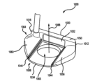
(b.三日月形の実施形態) 一実施形態では、パター型ゴルフクラブヘッドは、三日月形パターヘッド300とすることができる。図3A~3Cを参照すると、三日月形パターヘッド300は、上部304および下部308を有する。上部304は、第1の密度を有する第1の材料から作られ、下部308は、第2の密度を有する第2の材料から作られる。第1の密度は、第2の密度よりも小さい。上部304と下部308とが組み合わさって、バランスのとれたパターヘッド300を作り出す一方で、所望の体積および質量を維持する。高密度下部308および低密度上部304は、パターヘッド300の周辺近くにより多くの質量を配置する。したがって、同じ体積、質量、および単一材料構造を有するパターに対して、MOIおよび安定性が増大する。
b. Crescent-Shaped Embodiment In one embodiment, the putter-type golf club head can be a crescent-shaped
上述のように、下部308は、高密度材料(すなわち、第2の材料)から構成される。下部308は、リア周辺部352と、トウ端部312と、ヒール端部316と、打撃フェース320と、リアウォール332と、バックエッジ334と、クラウン342と、下面(図示せず)とを含む。下面および上部304は、ソール368を形成する。トウ端部312は、ヒール端部316の反対側にある。下部308のトウ端部312およびヒール端部316は、それぞれトウ側周辺部356およびヒール側周辺部360を含む。打撃フェース320は、トウ端部312からヒール端部316にかけて、リアウォール332に対向している。リアウォール332は、打撃フェース320と反対であり、ほぼ平行である。下部は、ヒール側周辺部360、トウ側周辺部356、フロントエッジ348、およびアッパーエッジ312をさらに備える。
As described above, the
フロントエッジ348は、トウ側周辺部356及びヒール側周辺部360に隣接し、リア周辺部352と反対側にある。トウ側周辺部356は、フロントエッジ348およびリア周辺部352に隣接し、ヒール側周辺部360とは反対側である。ヒール側周辺部360はまた、フロントエッジ348及びリア周辺部352に隣接しているが、トウ側周辺部356とは反対側にある。
The
ほとんどの実施形態では、トウ側周辺部356は、直角(90°角)がトウ側周辺部356とフロントエッジ348との接合部に形成されるように、フロントエッジ348からバックエッジ352に向かって垂直に延びる。しかしながら、他の実施形態では、トウ側周辺部356は、任意の角度(0°~180°)がトウ側周辺部356とフロントエッジ348との接合部に形成され得るように、フロントエッジ348から任意の方向に延在することができる。さらに、ほとんどの実施形態では、ヒール側周辺部360は、直角(90°角)がヒール側周辺部360とフロントエッジ348との接合部に形成されるように、フロントエッジ348から垂直に延びる。しかしながら、他の実施形態では、ヒール側周辺部360は、任意の角度(0°~180°)がヒール側周辺部360とフロントエッジ348との接合部に形成され得るように、フロントエッジ348から任意の方向に延在することができる。
In most embodiments, the
フロントエッジ348、トウ側周辺部356、およびヒール側周辺部360は、開口364を形成する。開口364は、フロントエッジ348、トウ側周辺部356、およびヒール側周辺部360によって境界付けされる。開口364は、パターの体積及び質量の大部分を下部308の端部に移動させる。開口364は、任意の形状を含むことができるが、一実施形態では、開口364は、ほぼ長方形である。他の実施形態では、開口364は、円形、曲線形、三角形、台形、放物線形、ゴルフボール形、正方形、または任意の他の所望の幾何学的形状であり得る。
The
パターヘッド300の上部304は、クラウン342と、フロントエッジ370と、バックエッジ334とを備えている。クラウン342は、フロントエッジ370から離れて上部304のバックエッジ334まで延在する。フロントエッジ348からバックエッジ334にまたがるクラウン342に対して、下面は反対である。
The top 304 of the
いくつかの実施形態では、ヒール側周辺部360およびトウ側周辺部356は平行であり得るが、いくつかの実施形態では、ヒール側周辺部360およびトウ側周辺部356は平行ではない。いくつかの実施態様において、リア周辺部352及びフロントエッジ348は、平行であり得るが、いくつかの実施態様において、リア周辺部352及びフロントエッジ348は、平行でない。三日月形パターヘッド300のリア周辺部352は、ほぼ三日月形であり、したがって、リア周辺部352とフロントエッジ348とは平行ではない。リア周辺部352は、ヒール側周辺部360からトウ側周辺部356にわたる曲線であってもよい。リア周辺部352は、ヒール側周辺部360とリア周辺部352との間の接合部から、トウ側周辺部356とリア周辺部352との間の接合部まで、リア周辺部352に沿って測定された曲線長を含む。いくつかの実施形態では、リア周辺部352の曲線長は、4.5インチから6.5インチの間であり得る。いくつかの実施形態では、リア周辺部曲線長は、4.5インチ~4.75インチ、4.75インチ~5.0インチ、5.0インチ~5.25インチ、5.25インチ~5.5インチ、5.5インチ~5.75インチ、5.75インチ~6.0インチ、6.0インチ~6.25インチ、又は6.25インチ~6.5インチとすることができる。
In some embodiments, the
上部304と下部308とが接合されると、クラウン342は、打撃フェース320の間をリア周辺部352まで延びる。クラウン342は、ほとんどの実施形態では、トウ側周辺部356からの全クラブヘッド300幅のほぼ内側25%に及んでおり、ヒール側周辺部360からの全クラブヘッド300幅のほぼ内側25%に及んでいる。他の実施形態では、クラウン342は、全クラブヘッド300の全幅にわたって、ヒール316からトウ312方向に、連続的または不連続的に及ぶことができる。いくつかの実施形態では、クラウン342は、クラブヘッド300の全幅の90%未満、クラブヘッド300の全幅の80%未満、クラブヘッド300の全幅の70%未満、クラブヘッド300の全幅の60%未満、クラブヘッド300の全幅の50%未満、クラブヘッド300の全幅の40%未満、またはクラブヘッド300の全幅の30%未満に及ぶことができる。さらに、いくつかの実施形態では、クラウン342は、打撃フェース320からバックエッジ334まで実質的に平坦であるか、または打撃フェース320からバックエッジ334まで上昇することができる。ほとんどの実施形態において、クラウン342の上昇または下降は、直線、曲線、放物線、正弦波、または多項式の関数であり得る。
When the upper and
クラウン342は、アライメントトラフ355をさらに含む。アライメントトラフ355は、ヒール端部316およびトウ端部312から等距離にある。アライメントトラフ355は、リアウォール328に隣接し、打撃フェースに対してほぼ垂直である。アライメントトラフ355は、バックエッジ334、リアウォール332、およびヒール端部316上およびトウ端部312上のクラウン342、によって境界付けされる。ほとんどの実施形態では、アライメントトラフは、ゴルフボールの幅(約4.27cm)にほぼ等しく、ゴルフボールの幅を広げる視覚的アライメントフィールド(visual alignment field)を見る者に提供する。
The
さらに、パターヘッド300の上部304は、クラウン342上に1つまたは複数のアライメント機構344を備えることができる。アライメント機構344は、線、一連の線、フライス加工トラフ、円、破線、三角形、チャネル、または任意の他の所望のアライメント機構344のうちの任意の1つまたは組合せとすることができる。アライメント機構344は、クラウン342全体、クラウン342の一部、またはアライメントトラフ355上に等間隔で配置され得る。アライメントトラフ355に沿って延びるアライメント機構344は、パター300のリアウォール332からバックエッジ334までゴルフボールの幅を延びる視覚的アライメントフィールドを見る者に提供するように機能する。目的は、クラウン342および/またはアライメントトラフ355に沿ったこれらのアライメント機構344を用いて、パター300全体をゴルフボールと位置合わせすることである。
Additionally, the top 304 of the
図3Cを参照すると、上部304は、上部304が下部308よりもグラウンドプレーンから離れているように、下部308に固着することができる。ここで、グラウンドプレーン372は、パターヘッド300がゴルフボールに当たるアドレス位置にあるとき、下部308に接している。
Referring to FIG. 3C, the
図3Cを参照すると、パターヘッド300の打撃フェース320は、打撃フェース中心点376及びロフト面380を含む。打撃フェース中心点376は、クラウン342および上部304の下面から等距離であり、同様に、パターヘッド300のヒール端部316およびトウ端部312から等距離である。ロフト面380は、パターヘッド300の打撃フェース320に接している。さらに、ミッドプレーン316は、打撃フェース中心点376と交差し、ロフト面380に対して垂直である。さらに、図3Bを参照すると、y軸388は、ミッドプレーン384と交差し、グラウンドプレーン372に垂直である。
Referring to FIG. 3C, the striking face 320 of the
上部304と下部308とが接合されると、ヒール端部316は、トウ側周辺部356の少なくとも一部に重なるようになる。さらに、上部304と下部308とが接合されると、トウ端部312は、ヒール側周辺部360の少なくとも一部に重なるようになる。さらに、上部304と下部308とが接合されると、打撃フェース320は、フロントエッジ316の少なくとも一部に重なるようになる。最後に、上部304及び下部308は、バックエッジ364がリア周辺部332の少なくとも一部と重なるように接合される。
When the
フロントエッジ316、リア周辺部332、トウ側周辺部356、及び下部308のヒール側周辺部360は、上部304と組み合わされて、ソール368を形成する。ソール368は、グラウンドプレーン372に対して垂直である。ここで、グラウンドプレーン372は、パターヘッド300がゴルフボールに当たるアドレス位置にあるとき、ソール368に対して接している。パターヘッド300のソール368は、パターヘッド300のトウ端部312からパターヘッド300のヒール端部316まで延びている。
The
ほとんどの実施形態では、パターヘッド300のソール368は、完全に平坦であってもよい。いくつかの実施形態では、パターヘッド300のソール368は、ヒール324からトウ320の方向にわずかなアーチを有することができ、わずかなアーチは、線形または多項式の関数とすることができる。いくつかの実施形態では、パターヘッド300のソール368は、ヒール324からトウ320の方向に強いアーチを有することができ、強いアーチは、線形、または多項式の関数とすることができる。ソール368は、グラウンドプレーン372上にパターヘッド300を静止させるための表面を提供するように機能する。
In most embodiments, the sole 368 of the
図3Aを参照すると、一実施形態では、下部308は、トウ質量341およびヒール質量343をさらに備えることができる。トウ質量341およびヒール質量343は、下部308と一体であり、それぞれトウ側周辺部356およびヒール側周辺部360と接触している。トウ質量341およびヒール質量343は、下部308から、グラウンドプレーン372から離れる方向に、かつ上部304に向かって延在する。トウ質量341およびヒール質量343は、上部304をパターヘッド300の下部308に位置決めして整列させる手段を提供する。
3A, in one embodiment, the
さらに、トウ質量341およびヒール質量343は、これらの質量機能を有さないパターと比較した場合に、三日月形パターヘッド300のMOIを増大させるために、周辺部に重量を追加する追加の手段を提供する。これらの質量機能は、2~5グラム、3~7グラム、または1~6グラムの範囲の重量を有することができる。質量機能は、全て同じ重量を有することができ、または上記の範囲内で異なる重量であることができる。質量機能の重量は、1グラム、2グラム、3グラム、4グラム、5グラム、6グラム、または7グラムであり得る。トウ質量341およびヒール質量343は、それぞれ、以下の形状のうちの任意の1つまたは組合せとすることができる:長方形、三角形、角錐形、球形、三日月形、正方形、円筒形、卵形、楕円形、台形、五角形、六角形、八角形、または任意の他の所望の幾何学的または非幾何学的形状。
Additionally, the
図3Aを参照すると、トウ質量341およびヒール質量343は、リア周辺部352から離れて配置することができる。ここで、トウ質量341およびヒール質量343は、リア周辺部352に接触または交差しない。しかしながら、他の実施形態では、トウ質量341およびヒール質量343は、リア周辺部352上に配置することができる。このとき、トウ質量341およびヒール質量343は、リア周辺部352と一体であり、交差する。
Referring to FIG. 3A, the
一実施形態では、トウ質量341は、トウ側周辺部356とフロントエッジ348との接合部でフロントエッジ348上に配置されるが、他の実施形態では、トウ質量341は、トウ側周辺部356に沿った任意の場所に配置することができる。一実施形態では、ヒール質量343は、ヒール側周辺部360とフロントエッジ348との接合部でフロントエッジ348に配置されるが、他の実施形態では、ヒール質量343は、ヒール側周辺部360に沿った任意の場所に配置することができる。
In one embodiment, the
トウ質量341およびヒール質量343は、トウ質量341およびヒール質量343がパターヘッド300の慣性モーメントを増加させるように機能するように、集中質量のエリアを提供する。トウ質量341およびヒール質量343はパター300の重心から遠いので、トウ質量341をフロントエッジ348上またはその近くであってトウ側周辺部356上またはその近くに配置し、ヒール質量343をフロントエッジ348上またはその近くであってヒール側周辺部360上またはその近くにそれぞれ配置すると、MOIが増大する。トウ質量341およびヒール質量343は、第2の材料から一体的に形成することができ、第2の材料は、第1の材料よりも高密度である。
The
トウ質量341およびヒール質量343は、トウ質量341およびヒール質量343がパター300のMOIを増加させるだけでなく、上部304が下部308に接合するための追加の表面を提供するように、2つの機能を提供する。したがって、トウ質量341は、フロントトウ接着部分341と呼ぶこともでき、ヒール質量343は、フロントヒール接着部分343と呼ぶこともできる。
The
いくつかの実施形態では、上部304の下面、クラウン342、フロントエッジ370、およびバックエッジ334は、第1のキャビティ(図示せず)を形成することができる。第1のキャビティは、トウ端部312の下面からクラウン342に向かって内側に延在するが、クラウン342には到達しない。第1のキャビティは、バックエッジ334、クラウン342、およびフロントエッジ370によって境界付けされる。第1のキャビティは、下部308のトウ質量341を受け入れるように機能する。
In some embodiments, the underside of the
いくつかの実施態様において、上部304の下面、クラウン342、フロントエッジ370、及びバックエッジ334は、第2のキャビティ(図示せず)を形成することができる。第2のキャビティは、ヒール端部316の下面からクラウン342に向かって内側に延在するが、クラウン342には到達しない。第2のキャビティは、バックエッジ334、クラウン342、およびフロントエッジ370によって境界付けされる。第2のキャビティは、下部308のヒール質量343を受け入れるように機能する。
In some embodiments, the underside of the
第1および第2のキャビティは、任意の所望の幾何学的形状を含むことができる。しかしながら、ほとんどの実施形態では、第1および第2のキャビティは、対応するトウ質量341またはヒール質量343の幾何学的形状と類似または同一の幾何学的形状を備える。さらに、上部304が下部308に固定されると、第1のキャビティは、第1のキャビティがトウ質量341を取り囲むように配置され、第2のキャビティは、第2のキャビティがヒール質量343を取り囲むように配置される。
The first and second cavities can include any desired geometric shape. However, in most embodiments, the first and second cavities comprise a geometric shape similar or identical to that of the
低密度の第1の材料の上部304と高密度の第2の材料の下部308との組み合わせは、極端に重いパターを生成することなく、高MOIパター300を生成する。リアウォール332、リア周辺部352、トウ側周辺部356、および下部308のヒール側周辺部360によって形成される大きな開口364は、(単一の材料からミリングされたパターと比較して、)パターのMOIを増加させることができる、高密度であるが低体積の部分を形成する。単一材料パターは、所望の体積(50cc~75cc)および質量(340グラム~385グラム)を維持しながら、高密度材料を周辺に割り当てることができない。
The combination of a lower density first material
下部308は、ほとんどの実施形態では、パター300の体積の38%未満を構成する。いくつかの実施形態では、下部308は、パター300の総体積の37%未満、パター300の総体積の36%未満、パター300の総体積の35%未満、パター300の総体積の34%未満、パター300の総体積の33%未満、パター300の総体積の32%未満、パター300の総体積の31%未満、パター300の総体積の30%未満、パター300の総体積の29%未満、パター300の総体積の28%未満、またはパター300の総体積の27%未満を含む。
The
下部308はパター300の体積の半分未満を構成するが、下部308はパター300の全質量の少なくとも45%を構成する。いくつかの実施形態では、下部308は、パター300の質量の少なくとも46%、パター300の質量の少なくとも46%、パター300の質量の少なくとも47%、パター300の質量の少なくとも48%、パター300の質量の少なくとも49%、パター300の質量の少なくとも50%、パター300の質量の少なくとも51%、パター300の質量の少なくとも52%、パター300の質量の少なくとも53%、パター300の質量の少なくとも54%、またはパター300の全質量の少なくとも55%を構成する。
Although the
パターヘッド300の周囲への質量の有益なシフトは、同じ体積、質量、および単一材料構造(すなわち、単一ステンレス鋼ブロックのパターミル加工、または単一材料のパターインベストメント鋳造)を有するパターよりも、パター300のMOIを増加させる。
The beneficial shift of mass to the perimeter of the
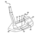
(c.半円形の実施形態) 一実施形態では、パター型ゴルフクラブヘッドは、半円形のパターヘッド400とすることができる。図4A~4Cを参照すると、半円形パターヘッド400は、上部404および下部408を有する。上部404は、第1の密度を有する第1の材料から作られ、下部408は、第2の密度を有する第2の材料から作られる。第1の密度は、第2の密度よりも小さい。上部404および下部408は、組み合わさって、所望の体積および質量を維持しながら、高MOIパターヘッド400(5000g・cm2-6500g・cm2)を生成する。
c. Semicircular embodiment In one embodiment, the putter-type golf club head can be a
上述のように、下部408は、高密度材料(すなわち、第2の材料)から構成される。下部408は、フロントエッジ448、リア周辺部452、トウ側スパン456、およびヒール側スパン460を備える。下部408と上部404の下面とが組み合わさってソール468を形成する。フロントエッジ448は、トウ側スパン456およびヒール側スパン460に隣接し、リア周辺部452とは反対である。トウ側スパン456は、フロントエッジ448およびリア周辺部452に隣接し、ヒール側スパン460とは反対側である。また、ヒール側スパン460は、フロントエッジ448およびリア周辺部452に隣接するが、トウ側スパン456とは反対である。トウ側スパン456およびヒール側スパン460は、上部404のリア周辺部448を越えて延在する。いくつかの実施形態では、ヒール側スパン460およびトウ側スパン456は、平行であり得るが、いくつかの実施形態では、ヒール側スパン460およびトウ側スパン456は、平行ではない。いくつかの実施態様では、リア周辺部452及びフロントエッジ448は平行であり得るが、いくつかの実施態様では、リア周辺部452及びフロントエッジ448は平行ではない。この実施態様において、リア周辺部452は、ほぼ半円形であり、したがって、リア周辺部452及びフロントエッジ448は、平行ではない。 As described above, the lower portion 408 is constructed from a high density material (i.e., the second material). The lower portion 408 includes a front edge 448, a rear perimeter 452, a toe span 456, and a heel span 460. The lower portion 408 and the underside of the upper portion 404 combine to form a sole 468. The front edge 448 is adjacent to the toe span 456 and the heel span 460, and is opposite the rear perimeter 452. The toe span 456 is adjacent to the front edge 448 and the rear perimeter 452, and is opposite the heel span 460. The heel span 460 is also adjacent to the front edge 448 and the rear perimeter 452, but is opposite the toe span 456. The toe span 456 and the heel span 460 extend beyond the rear perimeter 448 of the upper portion 404. In some embodiments, the heel span 460 and the toe span 456 can be parallel, but in some embodiments, the heel span 460 and the toe span 456 are not parallel. In some implementations, the rear perimeter 452 and the front edge 448 can be parallel, but in some implementations, the rear perimeter 452 and the front edge 448 are not parallel. In this implementation, the rear perimeter 452 is approximately semicircular, and therefore the rear perimeter 452 and the front edge 448 are not parallel.
ほとんどの実施形態では、トウ側スパン456は、直角(90°角)がトウ側スパン456とフロントエッジ448との接合部に形成されるように、フロントエッジ448から垂直に延びる。しかしながら、他の実施形態では、トウ側スパン456は、任意の角度(0°~180)がトウ側スパン456とフロントエッジ448との接合部に形成され得るように、フロントエッジ448から任意の方向に延在することができる。さらに、ほとんどの実施形態では、ヒール側スパン460は、直角(90°角)がヒール側スパン460とフロントエッジ448との接合部に形成されるように、フロントエッジ448から垂直に延びる。しかしながら、他の実施形態では、ヒール側スパン460は、任意の角度(0°~180)がヒール側スパン460とフロントエッジ448との接合部に形成され得るように、フロントエッジ448から任意の方向に延在することができる。 In most embodiments, the toe span 456 extends perpendicularly from the front edge 448 such that a right angle (90° angle) is formed at the junction of the toe span 456 and the front edge 448. However, in other embodiments, the toe span 456 can extend in any direction from the front edge 448 such that any angle (0° to 180°) can be formed at the junction of the toe span 456 and the front edge 448. Furthermore, in most embodiments, the heel span 460 extends perpendicularly from the front edge 448 such that a right angle (90° angle) is formed at the junction of the heel span 460 and the front edge 448. However, in other embodiments, the heel span 460 can extend in any direction from the front edge 448 such that any angle (0° to 180°) can be formed at the junction of the heel span 460 and the front edge 448.
フロントエッジ448、トウ側スパン456、およびヒール側スパン460は、ギャップ464を形成する。ギャップ464は、フロントエッジ448、トウ側スパン456、およびヒール側スパン460によって境界される。フロントエッジ448、トウ側スパン456、およびヒール側スパン460によって形成されるギャップ464は、パターの体積および質量の大部分を下部408の端部に移動させる。ギャップ464は、任意の形状を含むことができるが、一実施形態では、ギャップはほぼ矩形である。他の実施形態では、ギャップ464は、円形、曲線、三角形、台形、放物線、ゴルフボール形状、正方形、または任意の他の所望の幾何学的形状であり得る。 The front edge 448, the toe span 456, and the heel span 460 form a gap 464. The gap 464 is bounded by the front edge 448, the toe span 456, and the heel span 460. The gap 464 formed by the front edge 448, the toe span 456, and the heel span 460 moves most of the putter's volume and mass to the end of the lower portion 408. The gap 464 can include any shape, but in one embodiment, the gap is approximately rectangular. In other embodiments, the gap 464 can be circular, curvilinear, triangular, trapezoidal, parabolic, golf ball shaped, square, or any other desired geometric shape.
パターヘッド400の上部404は、トウ端部412、ヒール端部416、打撃フェース420、リアウォール432、バックエッジ434、クラウン442、および下面(図示せず)を備える。トウ端部412は、ヒール端部416の反対側にある。打撃フェース420は、トウ端部412からヒール端部416まで広がり、リアウォール432の反対側にある。リアウォール432は、反対であり、打撃フェース420とほぼ平行である。クラウン442は、打撃フェース420から離れて、上部404のバックエッジ434まで延びる。さらに、下面は、打撃フェース420からバックエッジ434にまたがる、クラウン442と反対である。
The top 404 of the
クラウン442は、打撃フェース420からバックエッジ434まで更に下降する。加えて、クラウン442は、打撃フェース420から離れて、下部408のフロントエッジ448を超えて、上部404のバックエッジ434まで延びる。クラウン442は、ほとんどの実施形態において、トウ側スパン456から全クラブヘッド400幅のほぼ内側25%に及んでおり、ヒール側スパン460から全クラブヘッド400幅のほぼ内側25%に及んでいる。他の実施形態では、クラウン442は、全クラブヘッド400の全幅を、ヒールからトウ方向に、連続的または不連続的に及ぶことができる。いくつかの実施形態では、クラウン442は、クラブヘッド400の全幅の90%未満、クラブヘッド400の全幅の90%未満、クラブヘッド400の全幅の80%未満、クラブヘッド400の全幅の70%未満、クラブヘッド400の全幅の60%未満、クラブヘッド400の全幅の50%未満、クラブヘッド400の全幅の40%未満、またはクラブヘッド400の全幅の30%未満に及ぶことができる。さらに、いくつかの実施形態では、クラウン442は、打撃フェース420からバックエッジ434まで実質的に平坦であるか、または打撃フェース420からバックエッジ434まで上昇することができる。ほとんどの実施形態では、クラウン442の上昇または下降は、直線、曲線、放物線、正弦波、または多項式の関数であり得る。
The
クラウン442は、アライメントトラフ455をさらに含む。アライメントトラフ455は、ヒール端部416およびトウ端部412から等距離にある。アライメントトラフ455は、リアウォール432に隣接し、打撃フェース420に対してほぼ垂直である。アライメントトラフ455は、バックエッジ434、リアウォール432、およびヒール端部416上のクラウン442、およびトウ端部412によって境界される。ほとんどの実施形態では、アライメントトラフ455は、ゴルフボールの幅(約4.27cm)にほぼ等しく、ゴルフボールの幅を広げる視覚的アライメントフィールド(visual alignment field)を見る者に提供する。
The
さらに、パターヘッド400の上部404は、クラウン442上に1つまたは複数のアライメント機構444を備えることができる。アライメント機構444は、線、一連の線、フライス加工トラフ、円、破線、三角形、チャネル、または任意の他の所望のアライメント機構444のうちの任意の1つまたは組合せとすることができる。アライメント機構444は、クラウン442全体、クラウン442の一部、またはアライメントトラフ455上に等間隔で配置され得る。アライメントトラフ455に沿って延びるアライメント機構444は、パター400のリアウォール432からバックエッジ434までゴルフボールの幅を延びる視覚的アライメントフィールドを見る者に提供するように機能する。目的は、クラウン442および/またはアライメントトラフ455に沿ったこれらのアライメント機構444を用いて、パター400全体をゴルフボールに位置合わせすることである。
Additionally, the top 404 of the
図4Cを参照すると、上部404は、上部404が下部408よりもグラウンドプレーン472からさらに離れるように下部408に固着される。ここでグラウンドプレーン472は、パターヘッド400がゴルフボールに当たるアドレス位置にあるときに、下部408に接する。
Referring to FIG. 4C, the upper portion 404 is affixed to the lower portion 408 such that the upper portion 404 is further away from the
さらに、パターヘッド400の打撃フェース420は、打撃フェース中心点476およびロフト面480を備える。打撃フェース中心点476は、クラウン442および上部404の下面から等距離であり、同様に、パターヘッド400のヒール端部416およびトウ端部412から等距離である。ロフト面480は、パターヘッド400の打撃フェース420に接している。さらに、ミッドプレーン484は、打撃フェース中心点476と交差し、ロフト面480に垂直である。さらに、y軸488は、ミッドプレーン484と交差し、グラウンドプレーン472に垂直である。
Further, the striking face 420 of the
上部404と下部408とが接合されると、ヒール端部416は、トウ側スパン456の少なくとも一部に重なるようになる。さらに、上部404と下部408とが接合されると、トウ端部412は、ヒール側スパン460の少なくとも一部に重なるようになる。さらに、上部404と下部408とが接合されると、打撃フェース420は、フロントエッジ448の少なくとも一部に重なるようになる。最後に、上部404と下部408は、バックエッジ434がリア周辺部452の少なくとも一部に重なるように接合される。 When the upper portion 404 and the lower portion 408 are joined, the heel end 416 overlaps at least a portion of the toe span 456. Furthermore, when the upper portion 404 and the lower portion 408 are joined, the toe end 412 overlaps at least a portion of the heel span 460. Furthermore, when the upper portion 404 and the lower portion 408 are joined, the striking face 420 overlaps at least a portion of the front edge 448. Finally, the upper portion 404 and the lower portion 408 are joined such that the back edge 434 overlaps at least a portion of the rear perimeter 452.
リア周辺部452は、ヒール側416からトウ側416にわたる曲線であってもよい。リア周辺部452は、ヒール側416とリア周辺部452との間の接合部からトウ側416とリア周辺部452との間の接合部まで、リア周辺部452に沿って測定された曲線長を含む。いくつかの実施態様において、リア周辺部452の曲線長は、4.5インチから8.0インチであり得る。いくつかの実施態様において、リア周辺部452の曲線長は、4.5インチ~4.75インチ、4.75インチ~5.0インチ、5.25インチ~5.5インチ、5.75インチ~6.0インチ、6.25インチ~6.5インチ、6.5インチ~6.75インチ、6.75インチ~7.0インチ、7.25インチ~7.50インチ、または、7.75インチ~8.0インチであり得る。 The rear perimeter 452 may be curvilinear from the heel side 416 to the toe side 416. The rear perimeter 452 includes a curvilinear length measured along the rear perimeter 452 from the junction between the heel side 416 and the rear perimeter 452 to the junction between the toe side 416 and the rear perimeter 452. In some embodiments, the curvilinear length of the rear perimeter 452 may be 4.5 inches to 8.0 inches. In some embodiments, the curvilinear length of the rear perimeter 452 may be 4.5 inches to 4.75 inches, 4.75 inches to 5.0 inches, 5.25 inches to 5.5 inches, 5.75 inches to 6.0 inches, 6.25 inches to 6.5 inches, 6.5 inches to 6.75 inches, 6.75 inches to 7.0 inches, 7.25 inches to 7.50 inches, or 7.75 inches to 8.0 inches.
下部408のフロントエッジ448、リア周辺部452、トウ側スパン456、およびヒール側スパン460は、上部404と組み合わされて、ソール468を形成する。ソール468はグラウンドプレーン472に垂直であり、パターヘッド400がゴルフボールを打つためのアドレス位置にあるとき、グラウンドプレーン472はソール468に接する。パターヘッド400のソール468は、パターヘッド400のトウ端部412からパターヘッド400のヒール端部416まで延びている。
The front edge 448, rear perimeter 452, toe span 456, and heel span 460 of the lower portion 408 combine with the upper portion 404 to form a sole 468. The sole 468 is perpendicular to a
ほとんどの実施形態において、パターヘッド400のソール468は、完全に平坦であり得る。いくつかの実施形態では、パターヘッド400のソール468は、ヒール416からトウ412の方向にわずかなアーチを有することができ、わずかなアーチは、線形、または多項式の関数とすることができる。いくつかの実施形態では、パターヘッド400のソール468は、ヒール416からトウ412の方向に強いアーチを有することができ、強いアーチは、線形、または多項式の関数とすることができる。ソール468は、グラウンドプレーン472上にパターヘッド400を静止させるための表面を提供するように機能する。
In most embodiments, the sole 468 of the
図4Aを参照すると、一実施形態では、下部408は、フロントトウ質量441およびフロントヒール質量443をさらに備えることができる。フロントトウ質量441、フロントヒール質量443は、下部408に一体化されている。フロントトウ質量441およびフロントヒール質量443は、下部408から、グラウンドプレーン472から離れる方向に、かつ上部404に向かって延在する。これらの質量部分は、上部404をパターヘッド400の下部408に位置決めして整列させる手段を提供する。さらに、これらの質量部分(すなわち、フロントトウ質量441およびフロントヒール質量443)は、これらの質量機能を有さないパターよりもパター400のMOIを増大させるために、周辺部に重量を追加する追加の手段を提供する。これらの質量機能は、2~5グラム、3~7グラム、または1~6グラムの範囲の重量を有することができる。質量機能は、全て同じ重量を有することができ、または上記の範囲内で異なる重量であることができる。質量機能は、1グラム、2グラム、3グラム、4グラム、5グラム、6グラム、または7グラムであり得る。フロントトウ質量441およびフロントヒール質量443は、それぞれ、以下の形状のうちの任意の1つまたは組み合わせであり得る:長方形、三角形、角錐形、球形、半円形、正方形、円筒形、卵形、楕円形、台形、五角形、六角形、八角形、または任意の他の所望の幾何学的または非幾何学的形状。
4A, in one embodiment, the lower portion 408 can further comprise a front toe mass 441 and a front heel mass 443. The front toe mass 441, the front heel mass 443 are integral to the lower portion 408. The front toe mass 441 and the front heel mass 443 extend from the lower portion 408 in a direction away from the
図4Aでは、フロントトウ質量441およびフロントヒール質量443は、リア周辺部452から離れて配置されている。ここで、フロントトウ質量441およびフロントヒール質量443は、リア周辺部452に接触または交差しない。しかし、図5A~5Cを参照すると、変形例の半円形状のパター500が示されている。パター500は、パター400と同じ特徴を有するが、パター500のフロントトウ質量541及びフロントヒール質量543は、リア周辺部552上に配置されている。フロントトウ質量541及びフロントヒール質量543は、リア周辺部452と一体であり、交差する。
In FIG. 4A, the front toe mass 441 and the front heel mass 443 are positioned away from the rear perimeter 452. Here, the front toe mass 441 and the front heel mass 443 do not contact or intersect the rear perimeter 452. However, with reference to FIGS. 5A-5C, an alternative semicircular
一実施形態では、フロントトウ質量441は、トウ側スパン456とフロントエッジ448との接合部であるフロントエッジ448上に配置される。しかしながら他の実施形態では、フロントトウ質量441は、トウ側スパン456に沿った任意の場所に配置することができる。一実施形態では、フロントヒール質量443は、ヒール側スパン460とフロントエッジ448の接合部であるフロントエッジ448上に配置される。しかし、他の実施形態では、フロントヒール質量443は、ヒール側スパン460に沿った任意の場所に配置することができる。 In one embodiment, the front toe mass 441 is located on the front edge 448 at the junction of the toe side span 456 and the front edge 448. However, in other embodiments, the front toe mass 441 can be located anywhere along the toe side span 456. In one embodiment, the front heel mass 443 is located on the front edge 448 at the junction of the heel side span 460 and the front edge 448. However, in other embodiments, the front heel mass 443 can be located anywhere along the heel side span 460.
フロントトウ質量441およびフロントヒール質量443は、各質量441、443がパターヘッド400の慣性モーメントを増加させるように機能するように、集中質量のエリアを提供する。各質量441、443はパター400の重心から離れているので、各質量441、443をフロントエッジ448およびスパン456、460に配置すると、MOIが増大する。周辺部448およびスパン456、460上の各質量441、443は、第2の材料から一体的に形成され、第2の材料は、第1の材料よりも高密度である。
The front toe mass 441 and the front heel mass 443 provide an area of concentrated mass such that each mass 441, 443 functions to increase the moment of inertia of the
フロントトウ質量441およびフロントヒール質量443は、フロントトウ質量441およびフロントヒール質量443がパター400のMOIを増大させるだけでなく、上部404が下部408に接合するための追加の表面を提供するように、2つの機能を提供する。したがって、フロントトウ質量441は、フロントトウ接着部分441と呼ぶこともでき、フロントヒール質量443は、フロントヒール接着部分443と呼ぶこともできる。
The front toe mass 441 and the front heel mass 443 serve two functions, as the front toe mass 441 and the front heel mass 443 not only increase the MOI of the
いくつかの実施形態では、上部404の下面、打撃フェース420、およびリアウォール432は、第1のキャビティ(図示せず)を形成することができる。第1のキャビティは、トウ端部412の下面からクラウン442に向かって内側に延在するが、クラウン442には到達しない。第1のキャビティは、リアウォール432、打撃フェース420、およびトウ412によって境界付けされる。第1のキャビティは、下部408のフロントトウ質量441を受け入れるように機能する。
In some embodiments, the underside of the upper portion 404, the striking face 420, and the rear wall 432 can form a first cavity (not shown). The first cavity extends inwardly from the underside of the toe end 412 toward, but not to, the
いくつかの実施形態では、上部404の下面、打撃フェース420、およびリアウォール432は、第2のキャビティ(図示せず)を形成することができる。第2のキャビティは、ヒール端部416の下面からクラウン442に向かって内側に延びるが、クラウン442には到達しない。第2のキャビティは、リアウォール432、打撃フェース420、およびヒール416によって境界付けされる。第2のキャビティは、下部408のフロントヒール質量443を受け入れるように機能する。
In some embodiments, the underside of the upper portion 404, the striking face 420, and the rear wall 432 can form a second cavity (not shown). The second cavity extends inwardly from the underside of the heel end 416 toward but not reaching the
第1および第2のキャビティは、任意の所望の幾何学的形状を含むことができるが、ほとんどの実施形態では、第1および第2のキャビティは、フロントトウ質量441およびフロントヒール質量443の幾何学的形状と類似または同一の幾何学的形状を含む。さらに、上部704が下部408に固定されるとき、第1のキャビティは、第1のキャビティがフロントトウ質量441を取り囲むように配置され、第2のキャビティは、第2のキャビティがフロントヒール質量443を取り囲むように配置される。
The first and second cavities can include any desired geometric shape, but in most embodiments, the first and second cavities include geometric shapes similar or identical to the geometric shapes of the front toe mass 441 and the front heel mass 443. Furthermore, when the
低密度の第1の材料の上部404と高密度の第2の材料の下部408との組み合わせは、極端に重いパターを生成することなく、高MOIパター400を生成する。リア周辺部452および下部408のスパン456、460によって形成される大きなギャップ464は、(単一の材料からミリングされたパターと比較して、)パターのMOIを増加させる、高密度であるが低体積の部分を形成する。単一材料パターは、所望の体積(75cc~100cc)および質量(340グラム~385グラム)を維持しながら、高密度材料を周辺に割り当てることができない。
The combination of a lower density first material upper portion 404 and a higher density second material lower portion 408 creates a
下部408は、ほとんどの実施形態では、パター400の体積の38%未満を構成する。いくつかの実施形態では、下部408は、パター400の総体積の37%未満、パター400の総体積の36%未満、パター400の総体積の35%未満、パター400の総体積の34%未満、パター400の総体積の33%未満、パター400の総体積の32%未満、パター400の総体積の31%未満、パター400の総体積の30%未満、パター400の総体積の29%未満、パター400の総体積の28%未満、またはパター400の総体積の27%未満を構成する。
The lower portion 408, in most embodiments, comprises less than 38% of the volume of the
下部408はパター400の体積の半分未満を構成するが、下部408はパター400の全質量の少なくとも45%を構成する。いくつかの実施形態では、下部408は、パター400の質量の少なくとも46%、パター400の質量の少なくとも46%、パター400の質量の少なくとも47%、パター400の質量の少なくとも48%、パター400の質量の少なくとも49%、パター400の質量の少なくとも50%、パター400の質量の少なくとも51%、パター400の質量の少なくとも52%、パター400の質量の少なくとも53%、パター400の質量の少なくとも54%、またはパター400の質量の少なくとも55%を構成する。
Although the lower portion 408 comprises less than half the volume of the
パターヘッド400の周囲への質量の有益なシフトは、高密度、低容積の下部408の使用を通して、同じ容積、質量、および単一材料構造(すなわち、単一ステンレス鋼ブロックでミリングされたパター、または単一材料のパターインベストメント鋳造物)を有するパターよりも、パター400のMOIを増加させる。
The beneficial shift of mass to the periphery of the
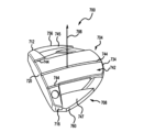
(d.ウィング型の実施形態) 一実施形態では、パター型ゴルフクラブヘッドは、周辺スパン600を有するウィング形パターヘッドとすることができる。図6Aおよび6Bを参照すると、ウィング形のパターヘッド600は、上部604および下部608を有する。上部604は、第1の密度を有する第1の材料から作製され、下部608は、第2の密度を有する第2の材料から作製される。第1の密度は、第2の密度よりも小さい。上部604および下部608は、組み合わさって、所望の体積および質量を維持しながら、高MOIパターヘッド600(5000g・cm2-6500g・cm2)を生成する。 d. Wing-Shaped Embodiments In one embodiment, the putter-type golf club head can be a wing-shaped putter head having a perimeter span 600. With reference to FIGS. 6A and 6B, the wing-shaped putter head 600 has an upper portion 604 and a lower portion 608. The upper portion 604 is made from a first material having a first density and the lower portion 608 is made from a second material having a second density. The first density is less than the second density. The upper portion 604 and the lower portion 608 combine to create a high MOI putter head 600 (5000 g cm2-6500 g cm2) while maintaining a desired volume and mass.
上述のように、下部608は、高密度材料(すなわち、第2の材料)から構成される。下部608は、フロント周辺部648と、ソール668と、リア周辺部652と、トウ側ウイング656と、ヒール側ウイング660とを含む。後述するように、図6Cは、下部608のフロント周辺部648、リア周辺部652、トウ側ウイング656、およびヒール側ウイング660が、上部604と組み合わさって、ソール668を生成する。フロント周辺部648は、トウ側周辺部656及びヒール側周辺部660に隣接し、リア周辺部652と反対側にある。トウ側ウイング656は、フロント周辺部648およびリア周辺部652に隣接し、ヒール側ウイング660とは反対である。また、ヒール側ウイング660は、フロント周辺部648およびリア周辺部652に隣接するが、トウ側ウイング656とは反対である。トウ側ウイング656およびヒール側ウイング660は、上部604のリア周辺部648を越えて延在する。いくつかの実施形態では、ヒール側ウイング660およびトウ側ウイング656は平行であってもよく、一方、いくつかの実施形態では、ヒール側ウイング660およびトウ側ウイング656は平行ではない。いくつかの実施態様では、リア周辺部652およびフロント周辺部648は、平行であり得るが、いくつかの実施態様では、リア周辺部652およびフロント周辺部648は、平行ではない。 As described above, the lower portion 608 is constructed from a high density material (i.e., the second material). The lower portion 608 includes a front perimeter 648, a sole 668, a rear perimeter 652, a toe wing 656, and a heel wing 660. As described below, FIG. 6C shows the front perimeter 648, rear perimeter 652, toe wing 656, and heel wing 660 of the lower portion 608 combined with the upper portion 604 to create the sole 668. The front perimeter 648 is adjacent to the toe perimeter 656 and the heel perimeter 660 and opposite the rear perimeter 652. The toe wing 656 is adjacent to the front perimeter 648 and the rear perimeter 652 and opposite the heel wing 660. Additionally, the heel wing 660 is adjacent to the front perimeter 648 and the rear perimeter 652, but opposite the toe wing 656. The toe wing 656 and the heel wing 660 extend beyond the rear perimeter 648 of the upper 604. In some embodiments, the heel wing 660 and the toe wing 656 may be parallel, while in some embodiments, the heel wing 660 and the toe wing 656 are not parallel. In some implementations, the rear perimeter 652 and the front perimeter 648 may be parallel, while in some implementations, the rear perimeter 652 and the front perimeter 648 are not parallel.
ほとんどの実施形態では、トウ側ウイング656は、直角(90°角)がトウ側ウイング656とリア周辺部652との接合部に形成されるように、リア周辺部652から垂直に延びる。しかしながら、他の実施形態では、トウ側ウイング656は、任意の角度(0°~180)がトウ側ウイング656とリア周辺部652との接合部に形成され得るように、リア周辺部652から任意の方向に延在することができる。さらに、ほとんどの実施形態では、ヒール側ウイング660は、直角(90°角)がヒール側ウイング660とリア周辺部652との接合部に形成されるように、リア周辺部652から垂直に延びる。しかしながら、他の実施形態では、ヒール側ウイング660は、任意の角度(0°~180)がヒール側ウイング660とリア周辺部652との接合部に形成され得るように、リア周辺部652から任意の方向に延在することができる。 In most embodiments, the toe side wing 656 extends perpendicularly from the rear perimeter 652 such that a right angle (90° angle) is formed at the junction of the toe side wing 656 and the rear perimeter 652. However, in other embodiments, the toe side wing 656 can extend in any direction from the rear perimeter 652 such that any angle (0° to 180°) can be formed at the junction of the toe side wing 656 and the rear perimeter 652. Furthermore, in most embodiments, the heel side wing 660 extends perpendicularly from the rear perimeter 652 such that a right angle (90° angle) is formed at the junction of the heel side wing 660 and the rear perimeter 652. However, in other embodiments, the heel side wing 660 can extend in any direction from the rear perimeter 652 such that any angle (0° to 180°) can be formed at the junction of the heel side wing 660 and the rear perimeter 652.
下部608のフロント周辺部648は、フロント幅を備える。フロント幅は、トウ側ウイング656とフロント周辺部648との接合部から、ヒール側ウイング660とフロント周辺部648との接合部まで測定される。さらに、下部608は、リア幅を有する。リア幅は、トウ側ウイング656の先端657およびヒール側ウイング660の先端661から測定される。ここで、先端657は、フロント周辺部648から最も遠いトウ側ウイング656の点であり、先端661は、フロント周辺部648から最も遠いヒール側ウイング660の点である。ほとんどの実施形態では、フロント幅はリア幅よりも大きいが、いくつかの実施形態では、フロント幅はリア幅以下とすることができる。 The front perimeter 648 of the lower portion 608 comprises a front width. The front width is measured from the junction of the toe wing 656 and the front perimeter 648 to the junction of the heel wing 660 and the front perimeter 648. Additionally, the lower portion 608 has a rear width. The rear width is measured from the tip 657 of the toe wing 656 and the tip 661 of the heel wing 660, where the tip 657 is the point of the toe wing 656 that is furthest from the front perimeter 648 and the tip 661 is the point of the heel wing 660 that is furthest from the front perimeter 648. In most embodiments, the front width is greater than the rear width, but in some embodiments, the front width can be less than or equal to the rear width.
リア周辺部652、トウ側ウイング656、およびヒール側ウイング660は、ギャップ664を形成する。ギャップ664は、リア周辺部652、トウ側ウイング656、およびヒール側ウイング660によって境界される。リア周辺部652、トウ側ウイング656、およびヒール側ウイング660によって形成されるギャップ664は、パターの体積および質量の大部分を下部608の端部に移動させる。ギャップ664は、任意の形状を含むことができるが、一実施形態では、ギャップは、ほぼ矩形である。他の実施形態では、ギャップ664は、円形、曲線、三角形、台形、放物線、ゴルフボール形状、正方形、または任意の他の所望の幾何学的形状であってもよい。 The rear perimeter 652, the toe wing 656, and the heel wing 660 form a gap 664. The gap 664 is bounded by the rear perimeter 652, the toe wing 656, and the heel wing 660. The gap 664 formed by the rear perimeter 652, the toe wing 656, and the heel wing 660 moves most of the putter's volume and mass to the end of the lower portion 608. While the gap 664 can include any shape, in one embodiment, the gap is approximately rectangular. In other embodiments, the gap 664 may be circular, curvilinear, triangular, trapezoidal, parabolic, golf ball shaped, square, or any other desired geometric shape.
パターヘッド600の上部604は、トウ端部612、ヒール端部616、打撃フェース620、リアウォール632、バックエッジ634、クラウン642、および下面(図示せず)を備える。トウ端部612は、ヒール端部616の反対側にある。打撃フェース620は、トウ端部612からヒール端部616まで広がり、リアウォール632の反対側にある。リアウォール632は、反対であり、打撃フェース620とほぼ平行である。クラウン642は、打撃フェース620から離れて、上部604のバックエッジ634まで延在する。さらに、下面は、打撃フェース620からバックエッジ634にまたがる、クラウン642と反対である。 The top 604 of the putter head 600 includes a toe end 612, a heel end 616, a striking face 620, a rear wall 632, a back edge 634, a crown 642, and an underside (not shown). The toe end 612 is opposite the heel end 616. The striking face 620 extends from the toe end 612 to the heel end 616 and is opposite the rear wall 632. The rear wall 632 is opposite and generally parallel to the striking face 620. The crown 642 extends away from the striking face 620 to the back edge 634 of the top 604. Additionally, the underside is opposite the crown 642, which spans from the striking face 620 to the back edge 634.
クラウン642は、打撃フェース620からバックエッジ634まで更に下降する。加えて、クラウン642は、打撃フェース620から離れて、下部608のフロント周辺部648を超えて、上部604のバックエッジ634まで延在する。クラウン642は、ほとんどの実施形態では、トウ側ウイング656からの全クラブヘッド600幅のほぼ内側25%に及んでおり、ヒール側ウイング660からの全クラブヘッド600幅のほぼ内側25%に及んでいる。他の実施形態では、クラウン642は、全クラブヘッド600の全幅を、ヒールからトウ方向に、連続的または不連続的に及ぶことができる。いくつかの実施形態では、クラウン642は、クラブヘッド600の全幅の90%未満、クラブヘッド600の全幅の90%未満、クラブヘッド600の全幅の80%未満、クラブヘッド600の全幅の70%未満、クラブヘッド600の全幅の60%未満、クラブヘッド600の全幅の50%未満、クラブヘッド600の全幅の40%未満、またはクラブヘッド600の全幅の30%未満に及ぶことができる。さらに、いくつかの実施形態では、クラウン642は、打撃フェース620からバックエッジ634まで実質的に平坦であるか、または打撃フェース620からバックエッジ634まで上昇することができる。ほとんどの実施形態において、クラウン642の上昇または下降は、直線、曲線、放物線、正弦波、または多項式の関数であり得る。 The crown 642 further descends from the striking face 620 to the back edge 634. Additionally, the crown 642 extends away from the striking face 620, past the front perimeter 648 of the lower portion 608, to the back edge 634 of the upper portion 604. In most embodiments, the crown 642 spans approximately the inner 25% of the total club head 600 width from the toe wing 656 and approximately the inner 25% of the total club head 600 width from the heel wing 660. In other embodiments, the crown 642 can span the entire width of the entire club head 600 in a heel-to-toe direction, either continuously or discontinuously. In some embodiments, the crown 642 can span less than 90% of the overall width of the club head 600, less than 90% of the overall width of the club head 600, less than 80% of the overall width of the club head 600, less than 70% of the overall width of the club head 600, less than 60% of the overall width of the club head 600, less than 50% of the overall width of the club head 600, less than 40% of the overall width of the club head 600, or less than 30% of the overall width of the club head 600. Additionally, in some embodiments, the crown 642 can be substantially flat from the striking face 620 to the back edge 634 or can rise from the striking face 620 to the back edge 634. In most embodiments, the rise or fall of the crown 642 can be a linear, curvilinear, parabolic, sinusoidal, or polynomial function.
クラウン642は、アライメントトラフ655をさらに含む。アライメントトラフ655は、ヒール端部616およびトウ端部612から等距離にある。アライメントトラフ655は、リアウォール632に隣接し、打撃フェース620に対してほぼ垂直である。アライメントトラフ655は、バックエッジ634、リアウォール632、およびヒール端部616上のクラウン642、およびトウ端部612によって境界される。ほとんどの実施形態では、アライメントトラフは、ゴルフボールの幅(約4.27cm)にほぼ等しく、ゴルフボールの幅を広げる視覚的アライメントフィールドを見る者に提供する。 The crown 642 further includes an alignment trough 655. The alignment trough 655 is equidistant from the heel end 616 and the toe end 612. The alignment trough 655 is adjacent to the rear wall 632 and is approximately perpendicular to the striking face 620. The alignment trough 655 is bounded by the back edge 634, the rear wall 632, and the crown 642 on the heel end 616 and toe end 612. In most embodiments, the alignment trough provides the viewer with a visual alignment field approximately equal to the width of a golf ball (approximately 4.27 cm) and extending the width of the golf ball.
さらに、パターヘッド600の上部604は、クラウン642上に1つまたは複数のアライメント機構644を備えることができる。アライメント機構644は、線、一連の線、フライス加工トラフ、円、破線、三角形、チャネル、または任意の他の所望のアライメント機構644のうちの任意の1つまたは組合せとすることができる。アライメント機構644は、クラウン642全体、クラウン642の一部、またはアライメントトラフ655上に等間隔で配置され得る。アライメントトラフ655に沿って延在するアライメント機構644は、パター600のリアウォール632からバックエッジ634までゴルフボールの幅を伸びる視覚的アライメントフィールドを見る者に提供するように機能する。目的は、クラウン642および/またはアライメントトラフ655に沿ったこれらのアライメント機構644を用いて、パター600全体をゴルフボールにアライメントすることである。 Additionally, the top 604 of the putter head 600 may include one or more alignment features 644 on the crown 642. The alignment features 644 may be any one or combination of lines, a series of lines, milled troughs, circles, dashed lines, triangles, channels, or any other desired alignment features 644. The alignment features 644 may be evenly spaced across the entire crown 642, a portion of the crown 642, or on the alignment troughs 655. The alignment features 644 extending along the alignment troughs 655 function to provide the viewer with a visual alignment field that extends the width of a golf ball from the rear wall 632 to the back edge 634 of the putter 600. The objective is to align the entire putter 600 to a golf ball using these alignment features 644 along the crown 642 and/or alignment troughs 655.
上部604は、下部608よりも上部604がグラウンドプレーン672から遠く離れるように、下部608に固着される。グラウンドプレーン672は、パターヘッド600がゴルフボールに当たるアドレス位置にあるとき、下部608に接する。 The upper portion 604 is affixed to the lower portion 608 such that the upper portion 604 is farther away from the ground plane 672 than the lower portion 608. The ground plane 672 contacts the lower portion 608 when the putter head 600 is in an address position to strike a golf ball.
さらに、パターヘッド600の打撃フェース620は、打撃フェース中心点676およびロフト面680を備える。打撃フェース中心点676は、クラウン642および上部604の下面から等距離であり、同様に、パターヘッド600のヒール端部616およびトウ端部612から等距離である。ロフト面680は、パターヘッド600の打撃フェース620に接している。さらに、ミッドプレーン684は、打撃フェース中心点676と交差し、ロフト面680に垂直である。さらに、y軸688は、ミッドプレーン684と交差し、グラウンドプレーン672に垂直である。 Further, the striking face 620 of the putter head 600 comprises a striking face center point 676 and a loft plane 680. The striking face center point 676 is equidistant from the crown 642 and the underside of the top portion 604, as well as equidistant from the heel end 616 and the toe end 612 of the putter head 600. The loft plane 680 is tangent to the striking face 620 of the putter head 600. Furthermore, a midplane 684 intersects the striking face center point 676 and is perpendicular to the loft plane 680. Furthermore, a y-axis 688 intersects the midplane 684 and is perpendicular to the ground plane 672.
上部604と下部608とが接合されると、ヒール端部616は、トウ側ウイング656の少なくとも一部に重なるようになる。さらに、上部604および下部608とが接合されると、トウ端部612は、ヒール側ウイング660の少なくとも一部に重なるようになる。さらに、上部604および下部608が接合されると、打撃フェース620は、フロント周辺部648の少なくとも一部に重なるようになる。最後に、上部604および下部608は、バックエッジ634がリア周辺部652の少なくとも一部に重なるように接合される。 When the upper portion 604 and the lower portion 608 are joined, the heel end 616 overlaps at least a portion of the toe wing 656. Furthermore, when the upper portion 604 and the lower portion 608 are joined, the toe end 612 overlaps at least a portion of the heel wing 660. Furthermore, when the upper portion 604 and the lower portion 608 are joined, the striking face 620 overlaps at least a portion of the front perimeter 648. Finally, the upper portion 604 and the lower portion 608 are joined such that the back edge 634 overlaps at least a portion of the rear perimeter 652.
図6Cを参照すると、下部608のフロント周辺部648、リア周辺部652、トウ側ウイング656、およびヒール側ウイング660は、上部604と組み合わされて、ソール668を生成する。ソール668は、グラウンドプレーン672に垂直である。グラウンドプレーン672は、パターヘッド600がゴルフボールに当たるアドレス位置にあるとき、ソール668に接している。パターヘッド600のソール668は、パターヘッド600のトウ端部612からパターヘッド600のヒール端部616まで延びている。 Referring to FIG. 6C, the front perimeter 648, rear perimeter 652, toe wing 656, and heel wing 660 of the lower portion 608 combine with the upper portion 604 to create a sole 668. The sole 668 is perpendicular to a ground plane 672. The ground plane 672 is tangent to the sole 668 when the putter head 600 is in an address position to strike a golf ball. The sole 668 of the putter head 600 extends from the toe end 612 of the putter head 600 to the heel end 616 of the putter head 600.
ほとんどの実施形態では、パターヘッド600のソール668は、完全に平坦であってもよい。いくつかの実施形態では、パターヘッド600のソール668は、ヒール616からトウ612の方向にわずかなアーチを有することができ、わずかなアーチは、線形、または多項式の関数とすることができる。いくつかの実施形態では、パターヘッド600のソール668は、ヒール616からトウ612の方向に強いアーチを有することができ、強いアーチは、線形、または多項式の関数とすることができる。ソール668は、グラウンドプレーン672上にパターヘッド600を静止させるための表面を提供するように機能する。 In most embodiments, the sole 668 of the putter head 600 may be completely flat. In some embodiments, the sole 668 of the putter head 600 may have a slight arch from the heel 616 to the toe 612, where the slight arch may be a linear or polynomial function. In some embodiments, the sole 668 of the putter head 600 may have a strong arch from the heel 616 to the toe 612, where the strong arch may be a linear or polynomial function. The sole 668 functions to provide a surface for resting the putter head 600 on the ground plane 672.
図6Aを参照すると、一実施形態では、下部608は、フロントトウ質量641、フロントヒール質量643、トウウィング質量645、およびヒールウィング質量647をさらに備えることができる。フロントトウ質量641、フロントヒール質量643、トウウィング質量645、およびヒールウィング質量647は、下部608に一体である。フロントトウ質量641、フロントヒール質量643、トウウィング質量645、およびヒールウィング質量647は、下部608から、グラウンドプレーン672から離れる方向に、かつ上部604に向かって延在する。これらの質量部分は、上部604をパターヘッド600の下部608に位置決めし整列させる手段を提供する。さらに、これらの質量部分(すなわち、フロントトウ質量641、フロントヒール質量643、トウウィング質量645、およびヒールウィング質量647)は、これらの質量機能を有さないパターよりもパター600のMOIを増大させるために、周辺部に重量を追加する追加の手段を提供する。これらの質量機能は、2~5グラム、3~7グラム、または1~6グラムの範囲の重量を有することができる。質量機能は、全て同じ重量を有することができ、または上記の範囲内で異なる重量であることができる。質量機能は、1グラム、2グラム、3グラム、4グラム、5グラム、6グラム、または7グラムであり得る。フロントトウ質量641、フロントヒール質量643、トウウィング質量645、およびヒールウィング質量647は、それぞれ、長方形、三角形、ピラミッド形、球形、半円形、正方形、円筒形、卵形、楕円形、台形、五角形、六角形、八角形、または任意の他の所望の幾何学的または非幾何学的形状のうちの任意の1つまたは組合せとすることができる。 6A, in one embodiment, the lower portion 608 can further comprise a front toe mass 641, a front heel mass 643, a toe wing mass 645, and a heel wing mass 647. The front toe mass 641, the front heel mass 643, the toe wing mass 645, and the heel wing mass 647 are integral to the lower portion 608. The front toe mass 641, the front heel mass 643, the toe wing mass 645, and the heel wing mass 647 extend from the lower portion 608 in a direction away from the ground plane 672 and toward the upper portion 604. These masses provide a means for positioning and aligning the upper portion 604 with the lower portion 608 of the putter head 600. Additionally, these mass features (i.e., front toe mass 641, front heel mass 643, toe wing mass 645, and heel wing mass 647) provide additional means of adding weight to the perimeter to increase the MOI of the putter 600 over a putter without these mass features. These mass features can have weights ranging from 2-5 grams, 3-7 grams, or 1-6 grams. The mass features can all have the same weight or can be of different weights within the above ranges. The mass features can be 1 gram, 2 grams, 3 grams, 4 grams, 5 grams, 6 grams, or 7 grams. The front toe mass 641, front heel mass 643, toe wing mass 645, and heel wing mass 647 can each be any one or combination of rectangular, triangular, pyramidal, spherical, semicircular, square, cylindrical, oval, elliptical, trapezoidal, pentagonal, hexagonal, octagonal, or any other desired geometric or non-geometric shape.
一実施形態では、フロントトウ質量641は、トウ側ウィング656とフロント周辺部648との接合部においてフロント周辺部648上に配置される。しかしながら他の実施形態では、フロントトウ質量641は、フロント周辺部648に沿った任意の場所に配置することができる。一実施形態では、フロントヒール質量643は、ヒールウィング660とフロント周辺部648との接合部において、フロント周辺部648上に配置される。しかしながら他の実施形態では、フロントヒール質量643は、フロント周辺部648に沿った任意の場所に配置することができる。一実施形態では、トウウィング質量645は、トウ側ウィング656の一部の上に配置することができるが、他の実施形態では、トウウィング質量645は、トウ側ウィング656の一部または全体に沿った任意の場所に配置することができる。一実施形態では、ヒールウィング質量647は、ヒール側ウィング660の一部の上に配置することができるが、他の実施形態では、ヒールウィング質量647は、ヒール側ウィング660の一部または全体に沿って配置することができる。 In one embodiment, the front toe mass 641 is located on the front perimeter 648 at the junction of the toe wing 656 and the front perimeter 648. However, in other embodiments, the front toe mass 641 can be located anywhere along the front perimeter 648. In one embodiment, the front heel mass 643 is located on the front perimeter 648 at the junction of the heel wing 660 and the front perimeter 648. However, in other embodiments, the front heel mass 643 can be located anywhere along the front perimeter 648. In one embodiment, the toe wing mass 645 can be located on a portion of the toe wing 656, while in other embodiments, the toe wing mass 645 can be located anywhere along a portion or the entirety of the toe wing 656. In one embodiment, the heel wing mass 647 can be located on a portion of the heel wing 660, while in other embodiments, the heel wing mass 647 can be located along a portion or the entirety of the heel wing 660.
フロントトウ質量641、フロントヒールウィング質量643、トウウィング質量645、およびヒールウィング質量647は、各質量641、643、645、および647が、パターヘッド600の慣性モーメントを増加させるように機能するように、集中質量のエリアを提供する。各質量641、643、645、および647を周辺部648およびウィング656、660上に配置すると、各質量641、643、645、および647がパター600の重心から遠くなるので、MOIが増大する。周辺部648およびウィング656、660上の各質量641、643、645、647は、第2の材料から一体的に形成され、第2の材料は、第1の材料よりも高密度である。 The front toe mass 641, the front heel wing mass 643, the toe wing mass 645, and the heel wing mass 647 provide an area of concentrated mass such that each mass 641, 643, 645, and 647 functions to increase the moment of inertia of the putter head 600. Locating each mass 641, 643, 645, and 647 on the perimeter 648 and the wings 656, 660 increases the MOI by moving each mass 641, 643, 645, and 647 away from the center of gravity of the putter 600. Each mass 641, 643, 645, and 647 on the perimeter 648 and the wings 656, 660 is integrally formed from a second material, the second material being denser than the first material.
フロントトウ質量641およびフロントヒール質量643は、フロントトウ質量641およびフロントヒール質量643がパター600のMOIを増大させるだけでなく、上部604が下部608に接合するための追加の表面を提供するように、2つの機能を提供する。したがって、フロントトウ質量641は、フロントトウ接着部分641と呼ぶこともでき、フロントヒール質量643は、フロントヒール接着部分643と呼ぶこともできる。 The front toe mass 641 and the front heel mass 643 serve two functions, as the front toe mass 641 and the front heel mass 643 not only increase the MOI of the putter 600, but also provide an additional surface for the upper portion 604 to bond to the lower portion 608. Thus, the front toe mass 641 can also be referred to as the front toe attachment portion 641, and the front heel mass 643 can also be referred to as the front heel attachment portion 643.
いくつかの実施形態では、上部604の下面、打撃フェース620、およびリアウォール632は、第1のキャビティ(図示せず)を形成することができる。第1のキャビティは、トウ端部612上の下面からクラウン642に向かって内側に延在するが、クラウン642には到達しない。第1のキャビティは、リアウォール632、打撃フェース620、およびトウ612によって境界付けされる。第1のキャビティは、下部608のフロントトウ質量641を受け入れるように機能する。 In some embodiments, the underside of the upper portion 604, the striking face 620, and the rear wall 632 can form a first cavity (not shown). The first cavity extends inwardly from the underside above the toe end 612 toward, but not to, the crown 642. The first cavity is bounded by the rear wall 632, the striking face 620, and the toe 612. The first cavity functions to receive the front toe mass 641 of the lower portion 608.
いくつかの実施形態では、上部604の下面、打撃フェース620、およびリアウォール632は、第2のキャビティ(図示せず)を形成することができる。第2のキャビティは、ヒール端部616上の下面からクラウン642に向かって内側に延びるが、クラウン642には到達しない。第2のキャビティは、リアウォール632、打撃フェース620、およびヒール616によって境界付けされる。第2のキャビティは、下部608のフロントヒール質量643を受け入れるように機能する。 In some embodiments, the underside of the upper portion 604, the striking face 620, and the rear wall 632 can form a second cavity (not shown). The second cavity extends inwardly from the underside above the heel end 616 toward, but not to, the crown 642. The second cavity is bounded by the rear wall 632, the striking face 620, and the heel 616. The second cavity functions to receive the front heel mass 643 of the lower portion 608.
第1および第2のキャビティは、任意の所望の幾何学的形状を含むことができるが、ほとんどの実施形態では、第1および第2のキャビティは、フロントトウ質量641およびフロントヒール質量643の幾何学的形状と類似または同一の幾何学的形状を含む。さらに、上部604が下部608に固定されると、第1のキャビティは、第1のキャビティがフロントトウ質量641を取り囲むように配置され、第2のキャビティは、第2のキャビティがフロントヒール質量643を取り囲むように配置される。 The first and second cavities can include any desired geometric shape, but in most embodiments, the first and second cavities include geometric shapes similar or identical to the geometric shapes of the front toe mass 641 and the front heel mass 643. Furthermore, when the upper portion 604 is secured to the lower portion 608, the first cavity is positioned such that the first cavity surrounds the front toe mass 641 and the second cavity is positioned such that the second cavity surrounds the front heel mass 643.
低密度の第1の材料の上部604と高密度の第2の材料の下部608との組み合わせは、極端に重いパターを生成することなく、高MOIパター600を生成する。リア周辺部652と下部608のウイング656、660とによって形成される大きなギャップ664は、(単一の材料からミリングされたパターと比較して、)パターのMOIを増加させる、高密度であるが低体積の部分を形成する。単一材料パターは、所望の体積(75cc~100cc)および質量(340グラム~385グラム)を維持しながら、高密度材料を周辺に割り当てることができない。 The combination of a lower density first material upper portion 604 and a higher density second material lower portion 608 creates a high MOI putter 600 without creating an excessively heavy putter. The large gap 664 formed by the rear perimeter 652 and wings 656, 660 of the lower portion 608 creates a high density, but low volume portion that increases the MOI of the putter (compared to a putter milled from a single material). A single material putter cannot allocate high density material to the perimeter while maintaining the desired volume (75cc-100cc) and mass (340g-385g).
下部608は、ほとんどの実施形態では、パター600の全容積の38%未満を構成する。いくつかの実施形態では、下部608は、パター600の総体積の37%未満、パター600の総体積の36%未満、パター600の総体積の35%未満、パター600の総体積の34%未満、パター600の総体積の33%未満、パター600の総体積の32%未満、パター600の総体積の31%未満、パター600の総体積の30%未満、パター600の総体積の29%未満、パター600の総体積の28%未満、またはパター600の総体積の27%未満を含む。 The lower portion 608 comprises less than 38% of the total volume of the putter 600 in most embodiments. In some embodiments, the lower portion 608 comprises less than 37% of the total volume of the putter 600, less than 36% of the total volume of the putter 600, less than 35% of the total volume of the putter 600, less than 34% of the total volume of the putter 600, less than 33% of the total volume of the putter 600, less than 32% of the total volume of the putter 600, less than 31% of the total volume of the putter 600, less than 30% of the total volume of the putter 600, less than 29% of the total volume of the putter 600, less than 28% of the total volume of the putter 600, or less than 27% of the total volume of the putter 600.
下部608は、パター600の体積の半分未満を構成するが、下部608は、パター600の全体質量の少なくとも45%を構成する。いくつかの実施形態では、下部608は、パター600の全体質量の少なくとも46%、パター600の全体質量の少なくとも46%、パター600の全体質量の少なくとも47%、パター600の全体質量の少なくとも48%、パター600の全体質量の少なくとも49%、パター600の全体質量の少なくとも50%、パター600の全体質量の少なくとも51%、パター600の全体質量の少なくとも52%、パター600の全体質量の少なくとも53%、パター600の全体質量の少なくとも54%、またはパター600の全体質量の少なくとも55%を構成する。 Although the lower portion 608 comprises less than half the volume of the putter 600, the lower portion 608 comprises at least 45% of the overall mass of the putter 600. In some embodiments, the lower portion 608 comprises at least 46% of the overall mass of the putter 600, at least 46% of the overall mass of the putter 600, at least 47% of the overall mass of the putter 600, at least 48% of the overall mass of the putter 600, at least 49% of the overall mass of the putter 600, at least 50% of the overall mass of the putter 600, at least 51% of the overall mass of the putter 600, at least 52% of the overall mass of the putter 600, at least 53% of the overall mass of the putter 600, at least 54% of the overall mass of the putter 600, or at least 55% of the overall mass of the putter 600.
高密度、低容積の下部608を使用することによる、パターヘッド600の周囲への質量の有益なシフトは、同じ容積、質量、および単一材料構造(すなわち、単一ステンレス鋼ブロックのパターミル加工、または単一材料のパターインベストメント鋳造)を有するパターよりも、パター600のMOIを増加させる。 The beneficial shift of mass to the periphery of the putter head 600 by using a high density, low volume lower portion 608 increases the MOI of the putter 600 over a putter having the same volume, mass, and single material construction (i.e., a putter milled from a single stainless steel block, or a single material putter investment cast).
(e.スペードの実施形態) 一実施形態では、パター型ゴルフクラブヘッドは、周辺スパン700を有するスペード形状のパターヘッドとすることができる。図7Aおよび7Bを参照すると、スペード形パターヘッド700は、上部704および下部708を有する。上部704は、第1の密度を有する第1の材料から作られ、下部708は、第2の密度を有する第2の材料から作られる。第1の密度は、第2の密度よりも小さい。上部704および下部708は、組み合わさって、所望の体積および質量を維持しながら、高MOIパターヘッド700(5000g・cm2-6500g・cm2)を生成する。
e. Spade embodiment In one embodiment, the putter-type golf club head can be a spade-shaped putter head having a
上述のように、下部708は、高密度材料(すなわち、第1の材料)から構成され、それによって、質量をミッドライン784より下に低下させる。下部708は、フロント周辺部748と、リア周辺部752と、トウ側周辺部756と、ヒール側周辺部760とを含む。フロント周辺部748は、トウ側周辺部756及びヒール側周辺部760に隣接し、リア周辺部752と反対側にある。トウ側周辺部756は、フロント周辺部748及びリア周辺部752に隣接し、ヒール側周辺部760とは反対側及び反対側にある。ヒール側周辺部760はまた、フロント周辺部748およびリア周辺部752に隣接するが、トウ側周辺部756とは反対側にある。いくつかの実施形態では、ヒール側周辺部760およびトウ側周辺部756は平行であり得るが、いくつかの実施形態では、ヒール側周辺部760およびトウ側周辺部756は平行ではない。いくつかの実施態様において、リア周辺部752及びフロント周辺部748は平行であり得るが、いくつかの実施態様において、リア周辺部752及びフロント周辺部748は平行でない。
As described above, the
下部708のフロント周辺部748は、フロント幅を備える。フロント幅は、トウ側周辺部756とフロント周辺部748との接合部から、ヒール側周辺部760とフロント周辺部748との接合部まで測定される。また、下部708のリア周辺部752は、リア幅を備える。リア幅は、トウ側周辺部756とリア周辺部752との接合部から、ヒール側周辺部760とリア周辺部752との接合部まで測定される。ほとんどの実施形態では、フロント幅はリア幅よりも大きいが、いくつかの実施形態では、フロント幅はリア幅以下とすることができる。
The
フロント周辺部748、リア周辺部752、トウ側周辺部756、およびヒール側周辺部760は、接合して開口764を形成している。ここで、開口764は、4つの周辺部(フロント748、リア752、トウ側756、およびヒール側760)によって境界される。4つの周辺部756、752、756、760は、開口764の周りに周辺部を形成する。下部708の周辺部756、752、756、760によって形成された中央開口764は、パターの体積及び質量の大部分を下部708の端部に移動させる。
The
パターヘッド700の上部704は、トウ端部712、ヒール端部716、打撃フェース720、リアウォール732、バックエッジ734、クラウン742、および下面(図示せず)を備える。トウ端部712は、ヒール端部716の反対側にある。打撃フェース720は、トウ端部712からヒール端部716まで広がり、リアウォール732の反対側にある。リアウォール732は、反対であり、打撃フェース720とほぼ平行である。クラウン742は、打撃フェース720から離れて、リアウォール732の少なくとも一部を覆って、上部704のバックエッジ734まで延びる。さらに、下面は、クラウン742の反対側にあり、打撃フェース720からバックエッジ734まで及ぶ。
The
クラウン742は、打撃フェース720からバックエッジ734まで更に下降する。加えて、クラウン742は、打撃フェース720から離れて、リアウォール732の少なくとも一部および下部708の開口764を超えて、上部704のバックエッジ734まで延びる。クラウン742は、ほとんどの実施形態において、トウ側周辺部756およびヒール側周辺部760からの全クラブヘッド700幅の内側25%に及んでいる。この実施形態では、クラウン742は、クラブヘッド700の幅の約50%に及んでいる。他の実施形態では、クラウン742は、全クラブヘッド700の全幅にわたって、ヒールからトウ方向へ及ぶことができる。いくつかの実施形態では、クラウン742は、クラブヘッド700の全幅の90%未満、クラブヘッド700の全幅の90%未満、クラブヘッド700の全幅の80%未満、クラブヘッド700の全幅の70%未満、クラブヘッド700の全幅の60%未満、クラブヘッド700の全幅の50%未満、クラブヘッド700の全幅の40%未満、またはクラブヘッド700の全幅の30%未満に及ぶことができる。さらに、いくつかの実施形態では、クラウン742は、打撃フェース720からバックエッジ734まで実質的に平坦であるか、または打撃フェース720からバックエッジ734まで上昇することができる。ほとんどの実施形態では、クラウン742の上昇または下降は、直線、曲線、放物線、正弦波、または多項式の関数であり得る。
The
さらに、パターヘッド700の上部704は、クラウン742上に1つまたは複数のアライメント機構744を備えることができる。アライメント機構744は、線、一連の線、フライス加工トラフ、円、破線、三角形、チャネル、または任意の他の所望のアライメント機構744のうちの任意の1つまたは組合せとすることができる。アライメント機構744は、クラウン742全体に等間隔で配置され、クラウンは、ゴルフボールの幅(約4.27cm)であるように構成される。クラウン742に沿って延びるアライメント機構744は、打撃フェース720からパター700のバックエッジ734までゴルフボールの幅を延びる視覚的アライメントフィールドを見る者に提供するように機能する。目的は、クラウン742に沿ったこれらのアライメント機構744を用いて、パター700全体をゴルフボールに位置合わせすることである。
Additionally, the top 704 of the
図7Cを参照すると、上部704は、上部704が下部708よりもグラウンドプレーン772からさらに離れているように下部708に固着される。ここでグラウンドプレーン772は、パターヘッド700がゴルフボールに当たるアドレス位置にあるとき、下部708に接している。
Referring to FIG. 7C, the
さらに、パターヘッド700の打撃フェース720は、打撃フェース中心点776およびロフト面780を備える。打撃フェース中心点776は、パターヘッド700のヒール端部716およびトウ端部712から等距離だけでなく、クラウン742および上部704の下面から等距離である。ロフト面780は、パターヘッド700の打撃フェース720に接している。さらに、ミッドプレーン784は、打撃フェース中心点776と交差し、ロフト面780に対して垂直である。さらに、y軸788は、ミッドプレーン784と交差し、グラウンドプレーン772に垂直である。
Further, the
上部704と下部708とが接合されると、ヒール端部716は、トウ側周辺部756の少なくとも一部に重なるようになる。さらに、上部704および下部708が接合されると、トウ端部712は、ヒール側周辺部760の少なくとも一部に重なるようになる。さらに、上部704と下部708とが接合されると、打撃フェース720は、フロント周辺部748の少なくとも一部に重なるようになる。最後に、上部704と下部708は、バックエッジ734がリア周辺部752の少なくとも一部に重なるように接合される。
When the
下部708の4つの周辺部(フロント748、リア752、トウ側756、およびヒール側760)は、上部704と組み合わされて、ソール768を生成する。ソール768は、グラウンドプレーン772に対して垂直である。グラウンドプレーン772は、パターヘッド700がゴルフボールに当たるアドレス位置にあるとき、ソール768に接する。パターヘッド700のソール768は、パターヘッド700のトウ端部712からパターヘッド700のヒール端部716まで延びている。
The four perimeters of the lower portion 708 (
ほとんどの実施形態では、パターヘッド700のソール768は、完全に平坦であってもよい。いくつかの実施形態では、パターヘッド700のソール768は、ヒール716からトウ712の方向にわずかなアーチを有することができ、わずかなアーチは、線形、または多項式の関数とすることができる。いくつかの実施形態では、パターヘッド700のソール768は、ヒール716からトウ712の方向に強いアーチを有することができ、強いアーチは、線形、または多項式の関数とすることができる。ソール768は、グラウンドプレーン772上にパターヘッド700を静止させるための表面を提供するように機能する。
In most embodiments, the sole 768 of the
図7Aを参照すると、一実施形態では、下部708は、フロント質量741、リア質量743、トウ質量745、およびヒール質量747をさらに備えることができる。フロント質量741、リア質量743、トウ質量745、およびヒール質量747は、下部708に一体である。フロント質量741、リア質量743、トウ質量745、およびヒール質量747は、下部708から、グラウンドプレーン772から離れる方向に、かつ上部704に向かって延在する。これらの質量部分は、上部704をパターヘッド700の下部708に位置決めして整列させるための手段を提供する。さらに、これらの質量部分(すなわち、フロント質量741、リア質量743、トウ質量745、およびヒール質量747)は、これらの質量機能を有さないパターよりもパター700のMOIを増大させるために、周辺部に重量を追加する追加の手段を提供する。これらの質量機能は、2~5グラム、3~7グラム、または1~6グラムの範囲の重量を有することができる。質量機能は、全て同じ重量を有することができ、または上記の範囲内で異なる重量であることができる。質量機能は、1グラム、2グラム、3グラム、4グラム、5グラム、6グラム、または7グラムであり得る。フロント質量741、リア質量743、トウ質量745、およびヒール質量747は、それぞれ、以下の形状のうちの任意の1つまたは組み合わせであり得る:長方形、三角形、角錐形、球形、半円形、正方形、円筒形、卵形、楕円形、台形、五角形、六角形、八角形、または任意の他の所望の幾何学的または非幾何学的形状。
7A, in one embodiment, the
一実施形態では、フロント質量741は、フロント周辺部748上に配置され、トウ側周辺部756およびヒール側周辺部760から等距離である。しかしながら他の実施形態では、フロント質量741は、フロント周辺部748に沿った任意の場所に配置され得る。一実施形態では、リア質量743は、リア周辺部752上に、トウ側周辺部756およびヒール側周辺部760から等距離で配置される。しかしながら他の実施形態では、リア質量743は、リア周辺部752に沿った任意の場所に配置することができる。一実施形態では、トウ質量745は、トウ側周辺部756とリア周辺部752との接合部に配置することができる。しかしながら他の実施形態では、トウ質量745は、トウ側周辺部756に沿った任意の場所に配置することができる。一実施形態では、ヒール質量747は、ヒール側周辺部760とリア周辺部752との接合部に配置することができる。しかしながら他の実施形態では、ヒール質量747は、ヒール側周辺部760に沿った任意の場所に配置することができる。
In one embodiment, the
フロント質量741、リア質量743、トウ質量745、およびヒール質量747は、各質量741、743、745、および747がパターヘッド700の慣性モーメントを増加させるように機能するように、集中質量のエリアを提供する。各質量748、752、756、760上に各質量741、743、745、および747を配置することにより、各質量741、743、745、および747がパター700の重心から離れているので、MOIが増大する。周辺部748、752、756、760上の各質量741、743、745、747は、第2の材料から一体的に形成され、第2の材料は、第1の材料よりも高密度である。
The
フロント質量741およびリア質量743は、フロント質量741およびリア質量743がパター700のMOIを増加させるだけでなく、上部704が下部708に接合するための付加的な表面を提供するように機能するように、2つの機能性を提供する。したがって、フロント質量741は、フロント接着部741およびリア質量743とも呼ぶことができる。
The
いくつかの実施形態では、上部704の下面、打撃フェース720、およびリアウォール732は、第1のキャビティ(図示せず)を形成することができる。第1のキャビティは、下面からクラウン742に向かって内側に延びるが、クラウン742には到達しない。第1のキャビティは、リアウォール732および打撃フェース720によって境界付けされる。第1のキャビティは、下部708のフロント質量741を受け入れるように機能する。
In some embodiments, the underside of the
いくつかの実施形態では、下面、バックエッジ734、およびクラウン742は、第2のキャビティ(図示せず)を形成する。第2のキャビティは、下面からクラウン742に向かって内側に延びるが、クラウン742には到達しない。第2のキャビティは、バックエッジ734、およびクラウン742によって境界付けされる。ほとんどの実施形態では、第2のキャビティは、下部708が上部704に接合されるとき、トウ側周辺部756とヒール側周辺部760との間に等距離に位置決めされる。第2のキャビティは、下部708のリア質量743を受け入れるように機能する。
In some embodiments, the lower surface, the
第1および第2のキャビティは、任意の所望の幾何学的形状を含むことができるが、ほとんどの実施形態では、第1および第2のキャビティは、フロント質量741およびリア質量743の幾何学的形状と類似または同一の幾何学的形状を含む。さらに、上部704が下部708に固定されると、第1のキャビティは、第1のキャビティがフロント質量741を取り囲むように配置され、第2のキャビティは、第2のキャビティがリア質量743を取り囲むように配置される。
The first and second cavities can include any desired geometric shape, but in most embodiments, the first and second cavities include geometric shapes similar or identical to the geometric shapes of the
低密度の第1の材料上部704と高密度の第2の材料下部708との組み合わせは、極端に重いパターを生成することなく、高MOIパター700を生成する。下部708の周辺部748、752、756、760によって形成された大きな開口764は、(単一材料からミリングされたパターと比較して、)パターのMOIを増大させる、高密度であるが低体積の部分を形成する。単一材料パターは、所望の体積(75cc~100cc)および質量(340グラム~385グラム)を維持しながら、高密度材料を周辺に割り当てることができない。
The combination of a low density first material
下部708は、ほとんどの実施形態では、パター700の全容積の35%未満を構成する。いくつかの実施形態では、下部708は、パター700の総体積の34%未満、パター700の総体積の33%未満、パター700の総体積の32%未満、パター700の総体積の31%未満、パター700の総体積の30%未満、パター700の総体積の29%未満、パター700の総体積の28%未満、またはパター700の総体積の27%未満を構成する。
The
下部708はパター700の体積の半分未満を構成するが、下部708はパター700の全質量の少なくとも45%を構成する。いくつかの実施形態では、下部708は、パター700の質量の少なくとも46%、パター700の質量の少なくとも47%、パター700の質量の少なくとも48%、パター700の質量の少なくとも49%、パター700の質量の少なくとも50%、パター700の質量の少なくとも51%、パター700の質量の少なくとも52%、パター700の質量の少なくとも53%、パター700の質量の少なくとも54%、またはパター700の質量の少なくとも55%を構成する。
Although the
パターヘッド700の周囲への質量の有益なシフトは、高密度、低容積の下部708の使用を通して、同じ容積、質量、および単一材料構造(すなわち、単一ステンレス鋼ブロックでミリングされたパター、または単一材料のパターインベストメント鋳造物)を有するパターに対して、パター700のMOIを増加させる。
The beneficial shift of mass to the periphery of the
(f.周辺スパンを有するT字形の実施形態) 一実施形態では、パター型ゴルフクラブヘッドは、周辺スパン800を有するT字型パターヘッドとすることができる。図8Aおよび図8Bを参照すると、周辺スパン800を有するT字型パターヘッドは、上部804および下部808を有する。上部804は、第1の密度を有する第1の材料から作製され、下部808は、第2の密度を有する第2の材料から作製される。第1の密度は、第2の密度よりも小さい。上部804および下部808は、組み合わさって、所望の体積および質量を維持しながら、高MOIパターヘッド800(5000g・cm2-6500g・cm2)を生成する。
f. T-Shaped Embodiment with Perimeter Span In one embodiment, the putter-type golf club head can be a T-shaped putter head with a
上述のように、下部808は、高密度材料(すなわち、第2の材料)から構成され、それによって、質量をミッドライン884より下に低下させる。下部808は、フロント周辺部848と、リア周辺部852と、トウ側周辺部856と、ヒール側周辺部860とを含む。フロント周辺部848は、トウ側周辺部856及びヒール側周辺部860に隣接し、リア周辺部852と反対側にある。トウ側周辺部856は、フロント周辺部848及びリア周辺部852に隣接し、ヒール側周辺部860とは反対側にある。ヒール側周辺部860はまた、フロント周辺部848およびリア周辺部852に隣接しているが、トウ側周辺部856とは反対側にある。いくつかの実施形態では、ヒール側周辺部860およびトウ側周辺部856は平行であり得るが、いくつかの実施形態では、ヒール側周辺部860およびトウ側周辺部856は平行ではない。いくつかの実施態様において、リア周辺部852及びフロント周辺部848は平行であり得るが、いくつかの実施態様において、リア周辺部852及びフロント周辺部848は平行でない。
As described above, the lower portion 808 is constructed from a high density material (i.e., the second material), thereby lowering the mass below the
下部808のフロント周辺部848は、フロント幅を備える。フロント幅は、トウ側周辺部856とフロント周辺部848との接合部から、ヒール側周辺部860とフロント周辺部848との接合部まで測定される。また、下部808のリア周辺部852は、リア幅を備える。リア幅は、トウ側周辺部856とリア周辺部852との接合部から、ヒール側周辺部860とリア周辺部852との接合部まで測定される。ほとんどの実施形態では、フロント幅はリア幅よりも大きいが、いくつかの実施形態では、フロント幅はリア幅以下とすることができる。 The front perimeter 848 of the lower portion 808 comprises a front width. The front width is measured from the junction of the toe side perimeter 856 and the front perimeter 848 to the junction of the heel side perimeter 860 and the front perimeter 848. And, the rear perimeter 852 of the lower portion 808 comprises a rear width. The rear width is measured from the junction of the toe side perimeter 856 and the rear perimeter 852 to the junction of the heel side perimeter 860 and the rear perimeter 852. In most embodiments, the front width is greater than the rear width, but in some embodiments, the front width can be less than or equal to the rear width.
フロント周辺部848、リア周辺部852、トウ側周辺部856、およびヒール側周辺部860は、接合して開口864を形成している。ここで、開口864は、4つの周辺部(フロント856、リア852、トウ側856、およびヒール側860)によって境界される。4つの周辺部856、852、856、860は、開口864の周りに周辺部を形成する。下部808の周辺部856、852、856、860によって形成される中央開口864は、パターの容積および質量の大部分を下部808の端部に移動させる。 The front perimeter 848, rear perimeter 852, toe perimeter 856, and heel perimeter 860 join to form an opening 864, where the opening 864 is bounded by four perimeters (front 856, rear 852, toe 856, and heel 860). The four perimeters 856, 852, 856, and 860 form a perimeter around the opening 864. The central opening 864 formed by the perimeters 856, 852, 856, and 860 of the lower portion 808 moves most of the putter's volume and mass to the end of the lower portion 808.
いくつかの実施形態では、フロント周辺部848、リア周辺部852、トウ側周辺部856、およびヒール側周辺部860によって形成される開口864は、以下の形状のうちの任意の1つであり得る:長方形、三角形、半円形、円形(ゴルフボールサイズ)、円形(ゴルフボールよりも大きい)、円形(ゴルフボールよりも小さい)、正方形、卵形、楕円形、台形、五角形、六角形、八角形、または任意の他の所望の幾何学的または非幾何学的形状。 In some embodiments, the opening 864 formed by the front perimeter 848, the rear perimeter 852, the toe perimeter 856, and the heel perimeter 860 can be any one of the following shapes: rectangular, triangular, semicircular, circular (golf ball size), circular (larger than a golf ball), circular (smaller than a golf ball), square, oval, elliptical, trapezoidal, pentagonal, hexagonal, octagonal, or any other desired geometric or non-geometric shape.
パターヘッド800の上部804は、トウ端部812、ヒール端部816、打撃フェース820、リアウォール832、バックエッジ834、クラウン842、および下面(図示せず)を備える。トウ端部812は、ヒール端部816の反対側にある。打撃フェース820は、トウ端部812からヒール端部816まで広がり、リアウォール832と反対側にある。リアウォール832は、反対であり、打撃フェース820とほぼ平行である。クラウン842は、打撃フェース820から離れて、リアウォール832の少なくとも一部を覆って、上部804のバックエッジ834まで延在する。さらに、下面は、クラウン842の反対側にあり、打撃フェース820からバックエッジ834まで及ぶ。
The top 804 of the
クラウン842は、打撃フェース820からバックエッジ834まで更に下降する。加えて、クラウン842は、打撃フェース820から離れて、リアウォール832の少なくとも一部および下部808の開口864を超えて、上部804のバックエッジ834まで延びる。クラウン842は、ほとんどの実施形態において、トウ側周辺部856およびヒール側周辺部860からの全クラブヘッド800幅の内側25%に及んでいる。この実施形態では、クラウン842は、クラブヘッド800の幅の約50%に及んでおり、したがって、打撃フェースと共に「T形状」を形成する。他の実施形態では、クラウン842は、全クラブヘッド800の全幅にわたって、ヒールからトウ方向へ及ぶことができる。いくつかの実施形態では、クラウン842は、クラブヘッド800の全幅の90%未満、クラブヘッド800の全幅の90%未満、クラブヘッド800の全幅の80%未満、クラブヘッド800の全幅の70%未満、クラブヘッド800の全幅の60%未満、クラブヘッド800の全幅の50%未満、クラブヘッド800の全幅の40%未満、またはクラブヘッド800の全幅の30%未満に及ぶことができる。さらに、いくつかの実施形態では、クラウン842は、打撃フェース820からバックエッジ834まで実質的に平坦であるか、または打撃フェース820からバックエッジ834まで上昇することができる。ほとんどの実施形態では、クラウン842の上昇または下降は、直線、曲線、放物線、正弦波、または多項式の関数であり得る。
The
さらに、パターヘッド800の上部804は、クラウン842上に1つまたは複数のアライメント機構844を備えることができる。アライメント機構844は、線、一連の線、フライス加工トラフ、円、破線、三角形、チャネル、または任意の他の所望のアライメント機構844のうちの任意の1つまたは組合せとすることができる。アライメント機構844は、クラウン842全体に等間隔で配置され、クラウンは、ゴルフボールの幅(約4.27cm)であるように構成される。クラウン842に沿って延びるアライメント機構844は、打撃フェース820からパター800のバックエッジ834までゴルフボールの幅を延びる視覚的アライメントフィールドを見る者に提供するように機能する。目的は、クラウン842に沿ったこれらのアライメント機構844を使用して、パター800全体をゴルフボールと位置合わせすることである。
Additionally, the top 804 of the
図8Cを参照すると、上部804は、上部804が下部808よりもグラウンドプレーン872から遠くになるように下部808に固着される。ここでグラウンドプレーン872は、パターヘッド800がゴルフボールに当たるアドレス位置にあるときに、下部808に接する。
Referring to FIG. 8C, the upper portion 804 is affixed to the lower portion 808 such that the upper portion 804 is farther from the
さらに、パターヘッド800の打撃フェース820は、打撃フェース中心点876およびロフト面880を備える。打撃フェース中心点876は、クラウン842および上部804の下面から等距離であり、同様に、パターヘッド800のヒール端部816およびトウ端部812から等距離である。ロフト面880は、パターヘッド800の打撃フェース820に接している。さらに、ミッドプレーン884は、打撃フェース中心点876と交差し、ロフト面880に垂直である。さらに、y軸888は、ミッドプレーン884と交差し、グラウンドプレーン872に垂直である。
Further, the striking face 820 of the
上部804と下部808とが接合されると、ヒール端部816は、トウ側周辺部856の少なくとも一部に重なるようになる。さらに、上部804および下部808とが接合されると、トウ端部812は、ヒール側周辺部860の少なくとも一部に重なるようになる。さらに、上部804と下部808とが接合されると、打撃フェース820は、フロント周辺部848の少なくとも一部に重なるようになる。最後に、上部804と下部808は、バックエッジ834がリア周辺部852の少なくとも一部に重なるように接合される。 When the upper portion 804 and the lower portion 808 are joined, the heel end 816 overlaps at least a portion of the toe perimeter 856. Furthermore, when the upper portion 804 and the lower portion 808 are joined, the toe end 812 overlaps at least a portion of the heel perimeter 860. Furthermore, when the upper portion 804 and the lower portion 808 are joined, the striking face 820 overlaps at least a portion of the front perimeter 848. Finally, the upper portion 804 and the lower portion 808 are joined such that the back edge 834 overlaps at least a portion of the rear perimeter 852.
下部808の4つの周辺部(フロント848、リア852、トウ側856、およびヒール側860)は、上部804と組み合わされて、ソール868を形成する。ソール868は、グラウンドプレーン872に対して垂直である。グラウンドプレーン872は、パターヘッド800がゴルフボールに当たるアドレス位置にあるとき、ソール868に接する。パターヘッド800のソール868は、パターヘッド800のトウ端部812からパターヘッド800のヒール端部816まで延びている。
The four perimeters of the lower portion 808 (front 848, rear 852, toe side 856, and heel side 860) combine with the upper portion 804 to form a sole 868. The sole 868 is perpendicular to a
ほとんどの実施形態では、パターヘッド800のソール868は、完全に平坦であり得る。いくつかの実施形態では、パターヘッド800のソール868は、ヒール816からトウ812の方向にわずかなアーチを有することができ、わずかなアーチは、線形、または多項式の関数とすることができる。いくつかの実施形態では、パターヘッド800のソール868は、ヒール816からトウ812の方向に強いアーチを有することができ、強いアーチは、線形、または多項式の関数とすることができる。ソール868は、グラウンドプレーン872上にパターヘッド800を静止させるための表面を提供するように機能する。
In most embodiments, the sole 868 of the
図8Aを参照すると、一実施形態では、下部808は、フロント質量841、リア質量843、トウ質量845、およびヒール質量847をさらに備えることができる。フロント質量841、リア質量843、トウ質量845、およびヒール質量847は、下部808と一体である。フロント質量841、リア質量843、トウ質量845、およびヒール質量847は、下部808から、グラウンドプレーン872から離れる方向に、かつ上部804に向かって延在する。これらの質量部分は、上部804をパターヘッド800の下部808に位置決めして整列させるための手段を提供する。さらに、これらの質量部分(すなわち、フロント質量841、リア質量843、トウ質量845、およびヒール質量847)は、これらの質量機能を有さないパターよりもパター800のMOIを増大させるために、周辺部に重量を追加する追加の手段を提供する。これらの質量機能は、2~5グラム、3~7グラム、または1~6グラムの範囲の重量を有することができる。質量機能は、全て同じ重量を有することができ、または上記の範囲内で異なる重量であることができる。質量機能は、1グラム、2グラム、3グラム、4グラム、5グラム、6グラム、または7グラムであり得る。フロント質量841、リア質量843、トウ質量845、およびヒール質量847は、それぞれ、以下の形状:長方形、三角形、角錐形、球形、半円形、正方形、円筒形、卵形、楕円形、台形、五角形、六角形、八角形、または任意の他の所望の幾何学的または非幾何学的形状のうちの任意の1つまたは組み合わせであり得る。
8A, in one embodiment, the lower portion 808 can further include a front mass 841, a rear mass 843, a toe mass 845, and a heel mass 847. The front mass 841, the rear mass 843, the toe mass 845, and the heel mass 847 are integral with the lower portion 808. The front mass 841, the rear mass 843, the toe mass 845, and the heel mass 847 extend from the lower portion 808 in a direction away from the
一実施形態では、フロント質量841は、フロント周辺部848上に配置され、トウ側周辺部856およびヒール側周辺部860から等距離である。しかしながら他の実施形態では、フロント質量841は、フロント周辺部848に沿った任意の場所に配置することができる。一実施形態では、リア質量843は、リア周辺部852上に、トウ側周辺部856およびヒール側周辺部860から等距離で配置される。しかしながら他の実施形態では、リア質量843は、リア周辺部852に沿った任意の場所に配置され得る。一実施形態では、トウ質量845は、トウ側周辺部856とリア周辺部852との接合部に配置することができる。しかしながら他の実施形態では、トウ質量845は、トウ側周辺部856に沿った任意の場所に配置することができる。一実施形態では、ヒール質量847は、ヒール側周辺部860とリア周辺部852との接合部に配置することができる。しかしながら他の実施形態では、ヒール質量847は、ヒール側周辺部860に沿った任意の場所に配置することができる。 In one embodiment, the front mass 841 is located on the front perimeter 848 and is equidistant from the toe side perimeter 856 and the heel side perimeter 860. However, in other embodiments, the front mass 841 can be located anywhere along the front perimeter 848. In one embodiment, the rear mass 843 is located on the rear perimeter 852 and is equidistant from the toe side perimeter 856 and the heel side perimeter 860. However, in other embodiments, the rear mass 843 can be located anywhere along the rear perimeter 852. In one embodiment, the toe mass 845 can be located at the junction of the toe side perimeter 856 and the rear perimeter 852. However, in other embodiments, the toe mass 845 can be located anywhere along the toe side perimeter 856. In one embodiment, the heel mass 847 can be located at the junction of the heel side perimeter 860 and the rear perimeter 852. However, in other embodiments, the heel mass 847 can be located anywhere along the heel side perimeter 860.
フロント質量841、リア質量843、トウ質量845、およびヒール質量847は、各質量841、843、845、および847がパターヘッド800の慣性モーメントを増加させるように機能するように、集中質量のエリアを提供する。周辺部848、852、856、860上の各質量841、843、845、および847の配置は、各質量841、843、845、および847がパター800の重心から遠いので、MOIを増加させる。周辺部848、852、856、860上の各質量841、843、845、847は、第2の材料から一体的に形成され、第2の材料は、第1の材料よりも高密度である。
The front mass 841, rear mass 843, toe mass 845, and heel mass 847 provide areas of concentrated mass such that each mass 841, 843, 845, and 847 functions to increase the moment of inertia of the
フロント質量841およびリア質量843は、フロント質量841およびリア質量843がパター800のMOIを増加させるだけでなく、上部804が下部808に接合するための付加的な表面を提供するように機能するように、2つの機能性を提供する。したがって、フロント質量841は、フロント接着部841およびリア質量843ともいうことができる。
The front mass 841 and rear mass 843 provide dual functionality as the front mass 841 and rear mass 843 not only increase the MOI of the
いくつかの実施形態では、上部804の下面、打撃フェース820、およびリアウォール832は、第1のキャビティ(図示せず)を形成することができる。第1のキャビティは、下面からクラウン842に向かって内側に延びるが、クラウン842には到達しない。第1のキャビティは、リアウォール832および打撃フェース820によって境界付けされる。第1のキャビティは、下部808のフロント質量841を受け入れるように機能する。
In some embodiments, the underside of the upper portion 804, the striking face 820, and the rear wall 832 can form a first cavity (not shown). The first cavity extends inwardly from the underside toward, but does not reach, the
いくつかの実施形態では、下面、バックエッジ834、およびクラウン842は、第2のキャビティ(図示せず)を形成する。第2のキャビティは、下面からクラウン842に向かって内側に延びるが、クラウン842には到達しない。第2のキャビティは、バックエッジ834、およびクラウン832によって境界される。ほとんどの実施形態では、第2のキャビティは、下部808が上部804に接合されるとき、トウ側周辺部856とヒール側周辺部860との間に等距離に位置決めされる。第2のキャビティは、下部808のリア質量843を受け入れるように機能する。
In some embodiments, the lower surface, the back edge 834, and the
第1および第2のキャビティは、任意の所望の幾何学的形状を含むことができるが、ほとんどの実施形態では、第1および第2のキャビティは、フロント質量841およびリア質量843の幾何学的形状と類似または同一の幾何学的形状を含む。さらに、上部804が下部808に固定されるとき、第1のキャビティは、第1のキャビティがフロント質量841を取り囲むように配置され、第2のキャビティは、第2のキャビティがリア質量843を取り囲むように配置される。 The first and second cavities can include any desired geometric shape, but in most embodiments, the first and second cavities include geometric shapes similar or identical to the geometric shapes of the front mass 841 and the rear mass 843. Furthermore, when the upper portion 804 is secured to the lower portion 808, the first cavity is positioned such that the first cavity surrounds the front mass 841 and the second cavity is positioned such that the second cavity surrounds the rear mass 843.
低密度の第1の材料の上部804と高密度の第2の材料の下部808との組み合わせは、極端に重いパターを生成することなく、高MOIパター800を生成する。下部808の周辺部848、852、856、860によって形成される大きな開口864は、(単一の材料からミリングされたパターと比較して、)パターのMOIを増大させる、高密度であるが低容積の部分を形成する。単一材料パターは、所望の体積(75cc~100cc)および質量(340グラム~385グラム)を維持しながら、高密度材料を周辺に割り当てることができない。
The combination of a lower density first material upper portion 804 and a higher density second material lower portion 808 creates a
下部808は、ほとんどの実施形態では、パター800の全容積の35%未満を構成する。いくつかの実施形態では、下部908は、パター800の総体積の34%未満、パター800の総体積の33%未満、パター800の総体積の32%未満、パター800の総体積の31%未満、パター800の総体積の30%未満、パター800の総体積の29%未満、パター800の総体積の28%未満、またはパター800の総体積の27%未満を構成する。
The lower portion 808, in most embodiments, comprises less than 35% of the total volume of the
下部808は、パター800の体積の半分未満を構成するが、下部808は、パター800の全体質量の少なくとも45%を構成する。いくつかの実施形態では、下部808は、パター800の質量の少なくとも46%、パター800の質量の少なくとも46%、パター800の質量の少なくとも46%、パター800の質量の少なくとも47%、パター800の質量の少なくとも48%、パター800の質量の少なくとも49%、パター800の質量の少なくとも50%、パター800の質量の少なくとも51%、パター800の質量の少なくとも52%、パター800の質量の少なくとも53%、パター800の質量の少なくとも54%、またはパター800の質量の少なくとも55%を構成する。
Although the lower portion 808 comprises less than half the volume of the
パターヘッド800の周辺部への質量の有益なシフトは、高密度、低容積下部808の使用を通して、同じ容積、質量、および単一材料構造(すなわち、単一ステンレス鋼ブロックでミリングされたパター、または単一材料のパターインベストメント鋳造物)を有するパターに対して、パター800のMOIを増加させる。
The beneficial shift of mass to the periphery of the
(g.デュアルレールの実施形態) 別の実施形態では、パター型ゴルフクラブヘッドは、デュアルレールパターヘッド900とすることができる。図9Aおよび図9Bを参照すると、デュアルレールパターヘッド900は、上部904および下部908を有する。上部904は、第1の密度を有する第1の材料から作られ、下部908は、第2の密度を有する第2の材料から作られる。第1の密度は、第2の密度よりも小さい。上部904および下部908は、組み合わさって、所望の体積および質量を維持しながら、高MOIパターヘッド900(5000g・cm2-6500g・cm2)を生成する。
g. Dual Rail Embodiment In another embodiment, the putter-type golf club head can be a dual
上述のように、下部908は、高密度材料(すなわち、第2の材料)から構成され、それによって、質量をミッドライン984より下に低下させる。下部908は、フロント周辺部948、リア周辺部952、トウ側周辺部956、およびヒール側周辺部960を備える。フロント周辺部948は、トウ側周辺部956及びヒール側周辺部960に隣接し、リア周辺部952と反対側にある。トウ側周辺部956は、フロント周辺部948及びリア周辺部952に隣接し、ヒール側周辺部960の反対側にある。ヒール側周辺部956はまた、フロント周辺部948およびリア周辺部952に隣接するが、トウ側周辺部956とは反対側にある。いくつかの実施形態では、ヒール側周辺部960およびトウ側周辺部956は平行であってもよく、一方、いくつかの実施形態では、ヒール側周辺部960およびトウ側周辺部956は平行ではない。いくつかの実施態様において、リア周辺部952及びフロント周辺部948は、平行であり得るが、いくつかの実施態様において、リア周辺部952及びフロント周辺部948は、平行ではない。
As described above, the lower portion 908 is constructed from a high density material (i.e., the second material), thereby lowering the mass below the
下部908のフロント周辺部948は、フロント幅を有する。フロント幅は、トウ側周辺部956とフロント周辺部948との接合部から、ヒール側周辺部960とフロント周辺部948との接合部まで測定される。さらに、下部908のリア周辺部952は、リア幅を有する。リア幅は、トウ側周辺部956とリア周辺部952との接合部から、ヒール側周辺部960とリア周辺部952との接合部まで測定される。ほとんどの実施形態では、フロント幅はリア幅よりも大きいが、いくつかの実施形態では、フロント幅はリア幅以下とすることができる。 The front perimeter 948 of the lower portion 908 has a front width. The front width is measured from the junction of the toe side perimeter 956 and the front perimeter 948 to the junction of the heel side perimeter 960 and the front perimeter 948. Additionally, the rear perimeter 952 of the lower portion 908 has a rear width. The rear width is measured from the junction of the toe side perimeter 956 and the rear perimeter 952 to the junction of the heel side perimeter 960 and the rear perimeter 952. In most embodiments, the front width is greater than the rear width, but in some embodiments, the front width can be less than or equal to the rear width.
フロント周辺部948、リア周辺部952、トウ側周辺部956、およびヒール側周辺部960は、接合して開口964を形成している。ここで、開口964は、4つの周辺部(フロント948、リア952、トウ側956、およびヒール側960)によって境界される。4つの周辺部948、952、956、960は、開口964の周りに周辺部を形成する。下部908の周辺部948、952、956、960によって形成された中央開口964は、パターの体積及び質量の大部分を下部908の端部に移動させる。 The front perimeter 948, rear perimeter 952, toe perimeter 956, and heel perimeter 960 join to form an opening 964, where the opening 964 is bounded by four perimeters (front 948, rear 952, toe 956, and heel 960). The four perimeters 948, 952, 956, and 960 form a perimeter around the opening 964. The central opening 964 formed by the perimeters 948, 952, 956, and 960 of the lower portion 908 moves most of the putter's volume and mass to the end of the lower portion 908.
いくつかの実施形態では、フロント周辺部948、リア周辺部952、トウ側周辺部956、およびヒール側周辺部960によって形成される開口964は、以下の形状のうちの任意の1つであり得る:長方形、三角形、半円形、円形(ゴルフボールサイズ)、円形(ゴルフボールよりも大きい)、円形(ゴルフボールよりも小さい)、正方形、卵形、楕円形、台形、五角形、六角形、八角形、または任意の他の所望の幾何学的または非幾何学的形状。 In some embodiments, the opening 964 formed by the front perimeter 948, the rear perimeter 952, the toe side perimeter 956, and the heel side perimeter 960 can be any one of the following shapes: rectangular, triangular, semicircular, circular (golf ball size), circular (larger than a golf ball), circular (smaller than a golf ball), square, oval, elliptical, trapezoidal, pentagonal, hexagonal, octagonal, or any other desired geometric or non-geometric shape.
デュアルレールパターヘッド900の上部904は、トウ端部912、ヒール端部916、打撃フェース920、リアウォール932、バックエッジ934、クラウン942、および下面(図示せず)を備える。トウ端部912は、ヒール端部916の反対側にある。打撃フェース920は、トウ端部912からヒール端部916まで広がり、リアウォール932の反対側にある。リアウォール932は、反対であり、打撃フェース920とほぼ平行である。クラウン942は、打撃フェース920から離れて、リアウォール932の少なくとも一部を覆って、上部904のバックエッジ934まで延びる。さらに、下面は、クラウン942の反対側にあり、打撃フェース920からバックエッジ934にまで及ぶ。
The top 904 of the dual
上部904のクラウン942は、トウエンドミッドレール936およびヒールエンドミッドレール940をさらに備える。ほとんどの実施形態では、トウエンドミッドレール936およびヒールエンドミッドレール940は、ほぼ平行であり、一方、打撃フェース920に垂直である。さらに、トウエンドミッドレール936およびヒールエンドミッドレール940は、トウ側周辺部956またはヒール側周辺部960と接触しない。トウエンドミッドレール936およびヒールエンドミッドレール940は、それぞれトウ側周辺部956およびヒール側周辺部960の外周から、全クラブヘッド幅の約1/3内側にある。しかしながら、他の実施形態では、トウエンドミッドレール936およびヒールエンドミッドレール940は、それぞれトウ側周辺部およびヒール側周辺部の外周から、全クラブヘッド幅の1/3よりも内側にあることができる。トウエンドミッドレール936およびヒールエンドミッドレール940は、打撃フェース920からバックエッジ934に下降する。いくつかの実施形態では、トウエンドミッドレール936およびヒールエンドミッドレール940は、平行ではなく、打撃フェース920に対して垂直ではない。いくつかの実施形態では、トウエンドミッドレール936およびヒールエンドミッドレール940は、打撃フェース920からバックエッジ934まで実質的に平坦であってもよく、または打撃フェース920からバックエッジ934まで上昇してもよい。ほとんどの実施形態では、ミッドレール936、940の上昇または下降は、直線状、曲線状、放物線状、正弦波状、または多項式の関数であり得る。
The
さらに、デュアルレールパターヘッド900の上部904は、トウエンドミッドレール936およびヒールエンドミッドレール940上に、1つまたは複数のアライメント機構944を備えることができる。アライメント機構944は、線、円、破線、三角形、チャネル、または任意の他の所望のアライメント機構944のうちの任意の1つまたは組合せとすることができる。アライメント機構944は、ゴルフボールの幅(約4.27cm)となるようにレール936、940上に間隔を置いて配置される。アライメント機構944は、レールに沿って延在し、ゴルフボール打撃フェース920からパター900全体に延在する視覚的アライメントフィールドを見る者に提供する。目的は、トウエンドミッドレール936およびヒールエンドミッドレール940に沿ったこれらのアライメント機構944を用いて、パター900全体をゴルフボールに位置合わせさせることである。
Additionally, the top 904 of the dual
上部904は、下部908よりも上部904がグラウンドプレーン972から遠く離れるように下部908に固着される。グラウンドプレーン972は、デュアルレールパターヘッド900がゴルフボールに当たるアドレス位置にあるとき、下部908に接する。
The upper portion 904 is affixed to the lower portion 908 such that the upper portion 904 is farther away from the
さらに、デュアルレールパターヘッド900の打撃フェース920は、打撃フェース中心点976とロフト面980とを備える。打撃フェース中心点976は、クラウン942および上部904の下面から等距離であり、同様に、デュアルレールパターヘッド900のヒール端部916およびトウ端部912から等距離である。ロフト面980は、デュアルレールパターヘッド900の打撃フェース920に接している。さらに、ミッドプレーン984は、打撃フェース中心点976と交差し、ロフト面980に対して垂直である。さらに、y軸988は、ミッドプレーン984と交差し、グラウンドプレーン972に垂直である。
Further, the striking face 920 of the dual
上部904と下部908とが接合されると、ヒール端部916は、トウ側周辺部956の少なくとも一部に重なるようになる。さらに、上部904および下部908が接合されると、トウ端部912は、ヒール側周辺部960の少なくとも一部に重なるようになる。さらに、上部904と下部908とが接合されると、打撃フェース920は、フロント周辺部948の少なくとも一部に重なるようになる。最後に、上部904と下部908は、バックエッジ934がリア周辺部952の少なくとも一部に重なるように接合される。 When the upper portion 904 and the lower portion 908 are joined, the heel end 916 overlaps at least a portion of the toe side perimeter 956. Furthermore, when the upper portion 904 and the lower portion 908 are joined, the toe end 912 overlaps at least a portion of the heel side perimeter 960. Furthermore, when the upper portion 904 and the lower portion 908 are joined, the striking face 920 overlaps at least a portion of the front perimeter 948. Finally, the upper portion 904 and the lower portion 908 are joined such that the back edge 934 overlaps at least a portion of the rear perimeter 952.
図9Cを参照すると、下部908の4つの周辺部(フロント948、リア952、トウ側956、およびヒール側960)は、上部904と組み合わされて、ソール968を形成する。ソール968は、グラウンドプレーン972に対して垂直である。グラウンドプレーン972は、デュアルレールパターヘッド900が、ゴルフボールに当たるアドレス位置にあるとき、ソール968に接する。デュアルレールパターヘッド900のソール968は、デュアルレールパターヘッド900のトウ端部912からデュアルレールパターヘッド900のヒール端部916まで延びている。
Referring to FIG. 9C, the four perimeters of the lower portion 908 (front 948, rear 952, toe side 956, and heel side 960) combine with the upper portion 904 to form a sole 968. The sole 968 is perpendicular to a
ほとんどの実施形態では、デュアルレールパターヘッド900のソール968は、完全に平坦であり得る。いくつかの実施形態では、パターヘッド900のソール968は、ヒールからトウへの方向にわずかなアーチを有することができ、わずかなアーチは、線形、または多項式の関数とすることができる。いくつかの実施形態では、パターヘッド900のソール968は、ヒールからトウ方向に強いアーチを有することができ、強いアーチは、線形、または多項式の関数とすることができる。ソール968は、グラウンドプレーン972上にデュアルレールパターヘッド900を載置するための表面を提供するように機能する。
In most embodiments, the sole 968 of the dual
図9Aを参照すると、一実施形態では、下部908は、フロント質量941、リア質量943、トウ質量945、およびヒール質量947をさらに備えることができる。フロント質量941、リア質量943、トウ質量945、およびヒール質量947は、下部908に一体である。フロント質量941、リア質量943、トウ質量945、およびヒール質量947は、下部908から、グラウンドプレーン972から離れる方向に、かつ上部904に向かって延在する。これらの質量部分は、上部をデュアルレールパターヘッド900の下部に位置決めして整列させるための手段を提供する。さらに、これらの質量部分(すなわち、フロント質量941、リア質量943、トウ質量945、およびヒール質量947)は、これらの質量機能を有さないパターよりもパターのMOIを増加させるために、周辺部に重量を追加する追加の手段を提供する。これらの質量機能は、2~5グラム、3~7グラム、または1~6グラムの範囲の重量を有することができる。質量機能は、全て同じ重量を有することができ、または上記の範囲内で異なる重量であることができる。質量機能は、1グラム、2グラム、3グラム、4グラム、5グラム、6グラム、または7グラムであり得る。フロント質量941、リア質量943、トウ質量945、およびヒール質量947は、それぞれ、以下の形状のうちの任意の1つまたは組み合わせであり得る:長方形、三角形、角錐形、球形、半円形、正方形、円筒形、卵形、楕円形、台形、五角形、六角形、八角形、または任意の他の所望の幾何学的または非幾何学的形状。
9A, in one embodiment, the lower portion 908 can further comprise a front mass 941, a rear mass 943, a toe mass 945, and a heel mass 947. The front mass 941, the rear mass 943, the toe mass 945, and the heel mass 947 are integral to the lower portion 908. The front mass 941, the rear mass 943, the toe mass 945, and the heel mass 947 extend from the lower portion 908 in a direction away from the
一実施形態では、フロント質量941は、フロント周辺部948上に配置され、トウ側周辺部956およびヒール側周辺部960から等距離である。しかしながら他の実施形態では、フロント質量941は、フロント周辺部948に沿った任意の場所に配置することができる。一実施形態では、リア質量943は、トウ側周辺部956およびヒール側周辺部960から等距離であるリア周辺部952上に配置される。しかしながら他の実施形態では、リア質量943は、リア周辺部952に沿った任意の場所に配置することができる。一実施形態では、トウ質量945は、トウ側周辺部956とリア周辺部952との接合部に配置することができる。しかしながら他の実施形態では、トウ質量945は、トウ側周辺部956に沿った任意の場所に配置することができる。一実施形態では、ヒール質量947は、ヒール側周辺部960とリア周辺部952との接合部に配置することができる。しかしながら他の実施形態では、ヒール質量947は、ヒール側周辺部960に沿った任意の場所に配置することができる。 In one embodiment, the front mass 941 is located on the front perimeter 948 and is equidistant from the toe side perimeter 956 and the heel side perimeter 960. However, in other embodiments, the front mass 941 can be located anywhere along the front perimeter 948. In one embodiment, the rear mass 943 is located on the rear perimeter 952 that is equidistant from the toe side perimeter 956 and the heel side perimeter 960. However, in other embodiments, the rear mass 943 can be located anywhere along the rear perimeter 952. In one embodiment, the toe mass 945 can be located at the junction of the toe side perimeter 956 and the rear perimeter 952. However, in other embodiments, the toe mass 945 can be located anywhere along the toe side perimeter 956. In one embodiment, the heel mass 947 can be located at the junction of the heel side perimeter 960 and the rear perimeter 952. However, in other embodiments, the heel mass 947 can be located anywhere along the heel side perimeter 960.
フロント質量941、リア質量943、トウ質量945、およびヒール質量947は、各質量941、943、945、および947がパターヘッド900の慣性モーメントを増加させるように機能するように、集中質量のエリアを提供する。各質量がパター900の重心から遠いので、各質量941、943、945、および947を周辺部948、952、956、960上に配置することにより、各質量941、943、945、および947がMOIを増加させる。周辺部948、952、956、960上の各質量941、943、945、947は、第2の材料から一体的に形成され、第2の材料は、第1の材料よりも高密度である。
The front mass 941, rear mass 943, toe mass 945, and heel mass 947 provide an area of concentrated mass such that each mass 941, 943, 945, and 947 functions to increase the moment of inertia of the
フロント質量941、リア質量943、トウ質量945、およびヒール質量947は、各質量941、943、945、および947がパター900のMOIを増加させるだけでなく、上部904が下部908に接合するための付加的な表面を提供するように、2つの機能性を提供する。したがって、フロント質量941はフロント接着部分941と呼ぶこともでき、リア質量943はリア接着部分943と呼ぶこともでき、トウ質量945はトウ接着部分945と呼ぶこともでき、ヒール質量947はヒール接着部分947と呼ぶこともできる。
The front mass 941, rear mass 943, toe mass 945, and heel mass 947 provide dual functionality such that each mass 941, 943, 945, and 947 not only increases the MOI of the
さらに、上部904のクラウン942は、トウエンドキャップ949およびヒールエンドキャップ951を備える。トウエンドキャップ949およびヒールエンドキャップ951は、それぞれトウ質量945およびヒール質量947に嵌合するように機能する。トウエンドキャップ949は、トウエンドミッドレール936及びバックエッジ934に隣接している。ヒールエンドキャップ951は、ヒールエンドミッドレール940及びバックエッジ934に隣接している。ほとんどの実施形態では、トウエンドキャップ949およびヒールエンドキャップ951は同一の幾何学的形状を備えるが、いくつかの実施形態では、トウエンドキャップ949およびヒールエンドキャップ951は異なる幾何学的形状を備えることができる。
Additionally, the
ほとんどの実施形態では、クラウン942のトウエンドキャップ949およびヒールエンドキャップ951は、それぞれトウ質量945およびヒール質量947よりも大きい。その結果、トウエンドキャップ949およびヒールエンドキャップ951は、上部904が下部908に固定されたときにトウ質量945およびヒール質量947を覆う。さらに、上部904が下部908に固定されると、トウエンドキャップ949は、トウエンドキャップ949がトウ側周辺部956およびトウ質量945の少なくとも一部に重なるように配置される。さらに、上部904が下部908に固定されると、ヒールエンドキャップ951は、ヒールエンドキャップ951がヒール側周辺部960およびヒール質量960の少なくとも一部分を覆うように配置される。
In most embodiments, the toe end cap 949 and heel end cap 951 of the
いくつかの実施形態では、上部904の下面、打撃フェース920、およびリアウォール932は、第1のキャビティ(図示せず)を形成することができる。第1のキャビティは、下面からクラウン942に向かって内側に延びるが、クラウン942には到達しない。第1のキャビティは、リアウォール932および打撃フェース920によって境界付けされる。第1のキャビティは、下部908のフロント質量941を受け入れるように機能する。
In some embodiments, the underside of the upper portion 904, the striking face 920, and the rear wall 932 can form a first cavity (not shown). The first cavity extends inwardly from the underside toward, but does not reach, the
いくつかの実施形態では、下面、バックエッジ934、およびクラウン942は、第2のキャビティ(図示せず)を形成する。第2のキャビティは、下面からクラウン942に向かって内側に延びるが、クラウン942には到達しない。第2のキャビティは、バックエッジ934、トウキャップ949、およびヒールエンドキャップ951によって境界付けされる。ほとんどの実施形態では、第2のキャビティは、トウエンドキャップ949とヒールエンドキャップ951との間に等距離に配置される。第2のキャビティは、下部908のリア質量943を受け入れるように機能する。
In some embodiments, the lower surface, the back edge 934, and the
第1および第2のキャビティは、任意の所望の幾何学的形状を含むことができるが、ほとんどの実施形態では、第1および第2のキャビティは、フロント質量941およびリア質量943の幾何学的形状と類似または同一の幾何学的形状を含む。さらに、上部904が下部908に固定されると、第1のキャビティは、第1のキャビティがフロント質量941を取り囲むように配置され、第2のキャビティは、第2のキャビティがリア質量943を取り囲むように配置される。 The first and second cavities can include any desired geometric shape, but in most embodiments, the first and second cavities include geometric shapes similar or identical to the geometric shapes of the front mass 941 and the rear mass 943. Furthermore, when the upper portion 904 is secured to the lower portion 908, the first cavity is positioned such that the first cavity surrounds the front mass 941 and the second cavity is positioned such that the second cavity surrounds the rear mass 943.
低密度の第1の材料の上部904と高密度の第2の材料の下部908との組み合わせは、極端に重いパターを生成することなく、高MOIパター900を生成する。下部908の周辺部948、952、956、960によって形成された大きな開口964は、(単一の材料からミリングされたパターと比較して、)パターのMOIを増大させる、高密度であるが低体積の部分を形成する。単一材料パターは、所望の体積(75cc~100cc)および質量(340グラム~385グラム)を維持しながら、高密度材料を周辺に割り当てることができない。
The combination of a lower density first material upper portion 904 and a higher density second material lower portion 908 creates a
下部908は、ほとんどの実施形態では、パター900の全容積の35%未満を構成する。いくつかの実施形態では、下部908は、パター900の総体積の34%未満、パター900の総体積の33%未満、パター900の総体積の32%未満、パター900の総体積の31%未満、パター900の総体積の30%未満、パター900の総体積の29%未満、パター900の総体積の28%未満、またはパター900の総体積の27%未満を構成する。
The lower portion 908, in most embodiments, comprises less than 35% of the total volume of the
下部908は、パター900の体積の半分未満を構成するが、下部908は、パター900の全質量の少なくとも45%を構成する。いくつかの実施形態において、下部908は、パター900の質量の少なくとも46%、パター900の質量の少なくとも46%、パター900の少なくとも46%、パター900の質量の少なくとも47%、パター900の少なくとも48%、パター900の質量の少なくとも49%、パター900の少なくとも50%、パター900の質量の少なくとも51%、パター900の少なくとも52%、パター900の質量の少なくとも53%、パター900の質量の少なくとも54%、またはパター900の質量の少なくとも55%を構成する。
Although the lower portion 908 comprises less than half the volume of the
パターヘッド900の周辺部への質量の有益なシフトは、高密度、低容積の下部908の使用を通して、同じ容積、質量、および単一材料構造(すなわち、単一ステンレス鋼ブロックでミリングされたパター、または単一材料のパターインベストメント鋳造物)を有するパターに対して、パター900のMOIを増加させる。
The beneficial shift of mass to the periphery of the
(h.円形の実施形態) 別の実施形態では、パター型ゴルフクラブヘッド1000は、円形のパターヘッド1000とすることができる。図10A~10Cを参照すると、円形パターヘッド1000は、上部1004および下部1008を有する。下部1008は、第1の密度を有する第1の材料から作られ、上部1004は、第2の密度を有する第2の材料から作られる。第1の密度は、第2の密度よりも小さい。上部1004および下部1008は、組み合わさって、所望の体積および質量を維持しながら、高MOIパターヘッド1000(5000g・cm2-6500g・cm2)を生成する。
(h. Circular Embodiment) In another embodiment, the putter-type
上述のように、上部1004は、高密度材料(すなわち、第2の材料)から構成される。上部1004は、トウ端部1012と、ヒール端部1016と、打撃フェース1020と、リアウォール1032と、下面(図示せず)とを含む。トウ端部1012は、ヒール端部1016の反対側にある。打撃フェース1020は、トウ端部1012からヒール端部1016まで広がり、リアウォール1032の反対側にある。リアウォール1032は、反対であり、打撃フェース1020とほぼ平行である。
As described above, the
上部1004は、トウ側スパン1056およびヒール側スパン1060をさらに備える。トウ側スパン1056は、トウ端部1012に隣接し、ヒール側スパン1060の反対側にある。ヒール側スパン1060はまた、ヒール端部1016に隣接し、トウ側スパン1056の反対側にある。いくつかの実施形態では、ヒール側スパン1060およびトウ側スパン1056は平行であり得るが、いくつかの実施形態では、ヒール側スパン1060およびトウ側スパン1056は平行ではない。トウ側スパン1056およびヒール側スパン1060は、リアウォール1032および打撃フェース1020から離れる方向に延びている。
The
ほとんどの実施形態では、トウ側スパン1056は、トウ側スパン1056とリアウォール1032との接合部に直角(90°角)が形成されるようにリアウォール1032から垂直に延びる。しかしながら、他の実施形態では、トウ側スパン1056は、任意の角度(0°-180°)がトウ側スパン1056とリアウォール1032との接合部に形成され得るように、リアウォール1032から任意の方向に延在することができる。さらに、ほとんどの実施形態では、ヒール側スパン1060は、直角(90°角)がヒール側スパン1060とリアウォール1032との接合部に形成されるように、リアウォール1032から垂直に延びる。しかしながら、他の実施形態では、ヒール側スパン1060は、ヒール側スパン1060とリアウォール1032との接合部に任意の角度(0°-180°)を形成できるように、リアウォール1032から任意の方向に延在することができる。
In most embodiments, the
リアウォール1032、トウ側スパン1056、およびヒール側スパン1060は、ギャップ1064を形成する。ギャップ1064は、リアウォール1032、トウ側スパン1056、およびヒール側スパン1060によって境界される。リアウォール1032、トウ側スパン1056、およびヒール側スパン1060によって形成されるギャップ1064は、パターの体積および質量の大部分を上部1008の端部に移動させる。ギャップ1064は、任意の形状を含むことができるが、一実施形態では、ギャップはほぼ矩形である。他の実施形態では、ギャップ1064は、円形、曲線、三角形、台形、放物線、ゴルフボール形状、正方形、または任意の他の所望の幾何学的形状であってもよい。
The
パターヘッド1000の下部1008は、フロントエッジ1041、リアエッジ1034、トウエッジ1043、およびヒールエッジ1045を備える。フロントエッジ1041は、トウエッジ1043およびヒールエッジ1045に隣接し、リアエッジ1034とは反対である。トウエッジ1034は、フロントエッジ1041およびリアエッジ1034に隣接し、ヒールエッジ1045に反対である。また、ヒールエッジ1045は、フロントエッジ1041およびリアエッジ1034に隣接し、トウエッジ1043とは反対である。いくつかの実施形態では、トウエッジ1043およびヒールエッジ1045は平行であり得るが、いくつかの実施形態では、トウエッジ1043およびヒールエッジ1045は平行ではない。一部の実施形態では、フロントエッジ1041およびリアエッジ1034は平行であり得るが、一部の実施形態では、フロントエッジ1041およびリアエッジ1034は平行ではない。
The
前エッジ1041、リアエッジ1034、トウエッジ1043、およびヒールエッジ1045は、接合して開口1065を形成する。開口1065は、4つのエッジ(フロント1041、リア1034、トウ1043、ヒール1045)によって境界付けされる。4つのエッジ1041、1034、1043、1045は、開口1065の周りに周辺部を形成する。
The front edge 1041,
いくつかの実施形態では、フロントエッジ1041、リアエッジ1034、トウエッジ1043、およびヒールエッジ1045によって形成される開口1065は、以下の形状のうちの任意の1つであり得る:長方形、三角形、半円形、円形(ゴルフボールサイズ)、円形(ゴルフボールよりも大きい)、円形(ゴルフボールよりも小さい)、正方形、卵形、楕円形、台形、五角形、六角形、八角形、または任意の他の所望の幾何学的または非幾何学的形状。
In some embodiments, the
図10Cを参照すると、下部1008は、上部1004および下部1008の一部がグラウンドプレーン1072と交差するように、上部1004に固着される。グラウンドプレーン1072は、パターヘッド1000がゴルフボールに当たるアドレス位置にあるとき、下部1008に接している。
Referring to FIG. 10C, the
さらに、パターヘッド1000の打撃フェース1020は、打撃フェース中心点1076およびロフト面1080を備える。打撃フェース中心点1076は、上部1004の上側レール1050およびグラウンドプレーン1072から等距離にある。上側レール1050は、打撃フェース1020およびリアウォール1032に隣接し、一方、グラウンドプレーン1072に対向する。打撃フェース中心点1076はまた、パターヘッド1000のヒール端部1016及びトウ端部1012から等距離にある。ロフト面1080は、パターヘッド1000の打撃フェース1020に接している。さらに、ミッドプレーン1084は、打撃フェース中心点1076と交差し、ロフト面1080に垂直である。さらに、y軸1088は、ミッドプレーン1084と交差し、グラウンドプレーン1072に垂直である。
Further, the
上部1004と下部1008とが接合されると、トウ側スパン1056は、トウエッジ1043の少なくとも一部に重なるようになる。さらに、上部1004と下部1008とが接合されると、ヒール側スパン1060は、ヒールエッジ1045の少なくとも一部に重なるようになる。さらに、上部1004と下部1008とが接合されると、打撃フェース1020は、フロントエッジ1048の少なくとも一部に重なるようになる。最後に、下部1008が、打撃フェース1020、トウ側スパン1056、およびヒール側スパン1060の一部に固着されるように、上部1004および下部1008が接合されると、それによって、リアウォール1032、トウ側スパン1056、およびヒール側スパン1060によって形成されるギャップ1064の少なくとも一部が充填される。
When the
下部1008と、上部1004のトウ側スパン1056およびヒール側スパン1060とが組み合わされると、ソール1068が形成される。ソール1068は、グラウンドプレーン1072に対して垂直である。ここで、グラウンドプレーン1072は、パターヘッド1000がゴルフボールに当たるアドレス位置にあるとき、ソール1068に対して接する。パターヘッド1000のソール1068は、パターヘッド1000のトウ端部1012からパターヘッド1000のヒール端部1016まで延びている。
When the
ほとんどの実施形態では、パターヘッド1000のソール1068は、完全に平坦であり得る。いくつかの実施形態では、パターヘッド1000のソール1068は、ヒール1016からトウ1012の方向にわずかなアーチを有することができ、わずかなアーチは、線形、または多項式の関数とすることができる。いくつかの実施形態では、パターヘッド1000のソール1068は、ヒール1016からトウ1012の方向に強いアーチを有することができ、強いアーチは、線形、または多項式の関数とすることができる。ソール1068は、グラウンドプレーン1072上にパターヘッド1000を静止させるための表面を提供するように機能する。
In most embodiments, the sole 1068 of the
いくつかの実施形態では、上部1004は、クラウン(図示せず)をさらに備えることができる。クラウンは、打撃フェース1020から下部1008のバックエッジ1034まで延在する。さらにクラウンは、少なくとも下部の開口1065の一部を覆うとともに少なくともリアウォール1032の一部を覆って、打撃フェース1020からバックエッジ1034まで及んでいる。
In some embodiments, the
クラウンは、打撃フェース1020からバックエッジ1034までさらに下降することができる。クラウンは、ほとんどの実施形態において、トウ側スパン1056から全クラブヘッド1000幅のほぼ内側25%に及んでおり、ヒール側スパン1060から全クラブヘッド1000幅のほぼ内側25%に及んでいる。他の実施形態では、クラウンは、全クラブヘッド1000の全幅を、ヒールからトウ方向に、連続的または不連続的に及ぶことができる。いくつかの実施形態では、クラウンは、クラブヘッド1000の全幅の90%未満、クラブヘッド1000の全幅の90%未満、クラブヘッド1000の全幅の80%未満、クラブヘッド1000の全幅の70%未満、クラブヘッド1000の全幅の60%未満、クラブヘッド1000の全幅の50%未満、クラブヘッド1000の全幅の40%未満、またはクラブヘッド1000の全幅の30%未満に及ぶことができる。さらに、いくつかの実施形態では、クラウンは、打撃フェース1020からバックエッジ1034まで実質的に平坦であるか、または打撃フェース1020からバックエッジ1034まで上昇することができる。ほとんどの実施形態において、クラウンの上昇または下降は、線形、曲線、放物線、正弦波、または多項式の関数であり得る。
The crown may extend further down from the
さらに、パターヘッド1000の上部1004は、トウ側スパン1065およびヒール側スパン1060上に1つまたは複数のアライメント機構1044を備えることができる。アライメント機構1044は、線、一連の線、フライス加工トラフ、円、破線、三角形、チャネル、または任意の他の所望のアライメント機構1044のうちの任意の1つまたは組合せとすることができる。アライメント機構1044は、トウ側スパン1065およびヒール側スパン1060全体、クラウンの一部、またはクラウン全体に等間隔で配置され得る。トウ側スパン1056およびヒール側スパン1060に沿って延在するアライメント機構1044は、リアウォール1032からパター1000のバックエッジ1034まで、ゴルフボールの幅を延びる視覚的アライメントフィールドを見る者に提供するように機能する。目的は、トウ側スパン1056およびヒール側スパン1060および/またはクラウンに沿ったこれらのアライメント機構1044を用いて、パター1000全体をゴルフボールに位置合わせさせることである。
Additionally, the top 1004 of the
高密度の第1の材料上部1004と低密度の第2の材料下部1008との組み合わせは、極端に重いパターを生成することなく、高MOIパター1000を生成する。リアウォール1032および上部1004のスパン1056、1060によって形成される大きなギャップ1064は、(単一の材料からミリングされたパターと比較して、)パターのMOIを増加させる、高密度であるが低幅の周辺部を形成する。単一材料パターは、所望の体積(75cc~100cc)および質量(340グラム~385グラム)を維持しながら、高密度材料を周辺に割り当てることができない。
The combination of a high density first material
高密度の上部1004、および低容積低質量の下部1008の使用による、パターヘッド1000の周囲への質量の有益なシフトは、同じ容積、質量、および単一材料構造(すなわち、単一ステンレス鋼ブロックでミリングされたパター、または単一材料のパターインベストメント鋳造物)を有するパターに対して、パター1000のMOIを増加させる。
The beneficial shift of mass to the periphery of the
1つ又は複数の請求要素の置換は、再構成を構成し、補綴ではない。更に、問題に対する利点、他の有利な点及び解決を、特別な実施形態に関連して説明してきた。しかしながら、問題に対する利点、他の有利な点及び解決、並びに、任意の利点、有利な点又は解決を発生させ又は明らかとさせる任意の1つ又は複数の要素は、このような利点、有利な点、解決又は要素がこのような請求の範囲に明示的に述べられていない限り、請求の範囲の任意又はすべての要素の重大な、必須の、又は、本質的な特徴若しくは要素を構成するものではない。 Substitution of one or more claim elements constitutes a rearrangement, not a prosthesis. Moreover, advantages, other advantages, and solutions to a problem have been described in connection with particular embodiments. However, the advantages, other advantages, and solutions to a problem, and any one or more elements that give rise to or make apparent any advantage, advantage, or solution, do not constitute a critical, essential, or essential feature or element of any or all elements of a claim, unless such advantage, advantage, solution, or element is expressly recited in such claim.
ゴルフに対する規則は、時々変更される(例えば、全米ゴルフ協会(USGA)、英国ゴルフ協会(R&A)等のゴルフ標準組織及び/又は管理機関によって、新しい規則が適用されることがあり、又は、古いルールが撤廃若しくは変更されることがある)ため、本明細書に記載の装置、方法及び製品に関するゴルフ用品は、任意の特定時におけるゴルフのルールに適合し又は適合しないことがある。従って、本明細書に記載の装置、方法及び製品に関するゴルフ用品は、適合又は非適合ゴルフ用品として、公表され、売り出され、及び/又は、売却されることがある。本明細書に記載の装置、方法及び製品は、この点について制限されない。 Because the rules of golf change from time to time (e.g., new rules may be adopted, or old rules may be repealed or modified, by golf standards organizations and/or governing bodies such as the United States Golf Association (USGA), the Royal and American Golf Association (R&A), etc.), golf equipment related to the devices, methods, and products described herein may or may not conform to the rules of golf at any particular time. Accordingly, golf equipment related to the devices, methods, and products described herein may be advertised, offered for sale, and/or sold as conforming or non-conforming golf equipment. The devices, methods, and products described herein are not limited in this respect.
上記の例は、本明細書に記載されるパター型ゴルフクラブ、装置、方法、および製造物品に関連して記載されてもよい。一方、本明細書に記載の装置、方法及び製品は、ホッケー用スティック、テニスラケット、釣り竿、スキーのストック等の他のタイプのスポーツ用品に適用可能としてもよい。 The above examples may be described in relation to the putter-type golf clubs, devices, methods, and articles of manufacture described herein. However, the devices, methods, and articles of manufacture described herein may also be applicable to other types of sporting goods, such as hockey sticks, tennis racquets, fishing rods, ski poles, etc.
更に、本明細書に記載の実施形態及び制限は、実施形態及び/又は制限が、(1)請求の範囲に明示的に主張されていない、及び、(2)均等論の下で、請求の範囲における表現要素及び/又は制限と等価又は潜在的に等価である場合、公開主義の下で公衆に提供するものではない。 Furthermore, the embodiments and limitations described herein are not offered to the public under the doctrine of disclosure if the embodiments and/or limitations (1) are not expressly claimed in the claims and (2) are equivalent or potentially equivalent to the expressive elements and/or limitations in the claims under the doctrine of equivalents.
条項1:パター型ゴルフクラブヘッドであって、上部と下部とを備え、前記上部は第1の密度を有する第1の材料から作られ、前記下部は第2の密度を有する第2の材料から作られており、前記第1の密度は、前記第2の密度よりも小さく、前記下部は、フロント周辺部、トウ側周辺部、ヒール側周辺部、およびリア周辺部を備えており、前記下部は、前記フロント周辺部、前記トウ側周辺部、前記ヒール側周辺部、および前記リア周辺部によって境界付けされる開口をさらに備えており、前記上部は、ヒール端部と、トウ端部と、打撃フェースと、リアウォールと、バックエッジと、クラウンと、下面と、を備え、前記トウ端部は前記ヒール端部の反対側にあり、前記バックエッジは前記打撃フェースの反対側にあり、前記クラウンは、前記打撃フェースから前記リアウォールの少なくとも一部を越えて前記バックエッジまで延びており、前記下面は、前記打撃フェースから前記バックエッジまで広がるクラウンの反対側にあり、前記上部は前記下部に固着されており、前記上部は前記下部よりもグラウンドプレーンから離れており、前記ヒール端部は、前記ヒール側周辺部の少なくとも一部に重なっており、前記トウ端部は、前記トウ側周辺部の少なくとも一部に重なっており、前記打撃フェースは、前記フロント周辺部の少なくとも一部に重なっており、前記クラウンは、前記打撃フェースから前記リア周辺部にかけて広がっており、前記下部と前記上部とが結合してソールが形成されており、前記ゴルフクラブヘッドがアドレス位置にあるとき、前記ソールは前記グラウンドプレーンに接しており、前記打撃フェースはロフト面に接しており、前記ロフト面と前記グラウンドプレーンとの間にロフト角が形成されており、前記下部は、前記ゴルフクラブヘッドの体積の30%未満を構成しており、前記下部は、前記ゴルフクラブヘッドの質量の50%超を構成している、パター型ゴルフクラブヘッド。 Clause 1: A putter-type golf club head, comprising an upper portion and a lower portion, the upper portion being made of a first material having a first density and the lower portion being made of a second material having a second density, the first density being less than the second density, the lower portion having a front perimeter, a toe side perimeter, a heel side perimeter, and a rear perimeter, the lower portion further comprising an opening bounded by the front perimeter, the toe side perimeter, the heel side perimeter, and the rear perimeter, the upper portion having a heel end, a toe end, a striking face, a rear wall, a back edge, a crown, and a lower surface, the toe end being opposite the heel end, the back edge being opposite the striking face, the crown extending from the striking face to the back edge over at least a portion of the rear wall, and the lower surface extending from the striking face to the back edge. A putter-type golf club head, the putter-type golf club head being opposite the crown, the upper part being fixed to the lower part, the upper part being further from the ground plane than the lower part, the heel end overlapping at least a portion of the heel side periphery, the toe end overlapping at least a portion of the toe side periphery, the striking face overlapping at least a portion of the front periphery, the crown extending from the striking face to the rear periphery, the lower part and the upper part joining to form a sole, the sole contacting the ground plane when the golf club head is in an address position, the striking face contacting a loft plane, a loft angle being formed between the loft plane and the ground plane, the lower part making up less than 30% of the volume of the golf club head, and the lower part making up more than 50% of the mass of the golf club head.
条項2:前記下部は、前記トウ側周辺部と前記リア周辺部との接合部におけるトウ質量と、前記ヒール側周辺部と前記リア周辺部の接合部におけるヒール質量と、前記リア周辺部上に位置するとともに前記トウ側周辺部および前記ヒール側周辺部から等距離に位置しているリア質量と、前記フロント周辺部上に位置するとともに前記トウ側周辺部および前記ヒール側周辺部から等距離に位置しているフロント質量と、をさらに備える、条項1に記載のパター型ゴルフクラブヘッド。 Clause 2: The putter-type golf club head according to clause 1, wherein the lower portion further comprises a toe mass at the junction of the toe side peripheral portion and the rear peripheral portion, a heel mass at the junction of the heel side peripheral portion and the rear peripheral portion, a rear mass located on the rear peripheral portion and equidistant from the toe side peripheral portion and the heel side peripheral portion, and a front mass located on the front peripheral portion and equidistant from the toe side peripheral portion and the heel side peripheral portion.
条項3:前記トウ質量、前記ヒール質量、前記リア質量、および前記フロント質量は、前記下部と一体であるとともに、前記グラウンドプレーンから離れて前記上部に向かう方向へ前記下部から延びている、条項2に記載のパター型ゴルフクラブヘッド。 Clause 3: A putter-type golf club head as described in clause 2, wherein the toe mass, the heel mass, the rear mass, and the front mass are integral with the lower portion and extend from the lower portion in a direction away from the ground plane toward the upper portion.
条項4:前記上部の前記クラウンは、トウエンドミッドレールと、ヒールエンドミッドレールと、トウエンドキャップと、ヒールエンドキャップと、をさらに備える、条項1に記載のパター型ゴルフクラブヘッド。 Clause 4: The putter-type golf club head described in clause 1, wherein the upper crown further comprises a toe end mid-rail, a heel end mid-rail, a toe end cap, and a heel end cap.
条項5:前記トウエンドキャップは、前記トウ質量と嵌合するように構成されており、前記ヒールエンドキャップは、前記ヒール質量と嵌合するように構成されている、条項4に記載のパター型ゴルフクラブヘッド。 Clause 5: A putter-type golf club head as described in clause 4, wherein the toe end cap is configured to mate with the toe mass and the heel end cap is configured to mate with the heel mass.
条項6:前記上部は、第1のキャビティおよび第2のキャビティをさらに備えており、前記第1のキャビティは、前記打撃フェースと前記リアウォールとの間の前記下面に形成されているとともに前記クラウンに向かう方向に延びており、前記リア開口は、前記バックエッジに隣接して前記下面に形成されているとともに、前記トウエンドキャップおよび前記ヒールエンドキャップと等距離である、条項5に記載のパター型ゴルフクラブヘッド。 Clause 6: The putter-type golf club head of clause 5, wherein the upper portion further comprises a first cavity and a second cavity, the first cavity being formed in the underside between the striking face and the rear wall and extending in a direction toward the crown, and the rear opening being formed in the underside adjacent the back edge and equidistant to the toe end cap and the heel end cap.
条項7:前記第1のキャビティは、前記フロント質量と嵌合するように構成されており、前記第2のキャビティは、前記リア質量と嵌合するように構成されている、条項6に記載のパター型ゴルフクラブヘッド。 Clause 7: The putter-type golf club head described in clause 6, wherein the first cavity is configured to mate with the front mass and the second cavity is configured to mate with the rear mass.
条項8:前記トウエンドミッドレールおよび前記ヒールエンドミッドレールは、前記打撃フェースから前記リア周辺部へ下降している、条項4に記載のパター型ゴルフクラブヘッド。 Clause 8: A putter-type golf club head as described in clause 4, wherein the toe-end mid-rail and the heel-end mid-rail descend from the striking face to the rear periphery.
条項9:前記ヒールエンドミッドレールおよび前記トウエンドミッドレールは、前記ヒールエンドミッドレールおよび前記トウエンドミッドレール上に1つ以上のアライメント機構を備える、条項4に記載のパター型ゴルフクラブヘッド。 Clause 9: The putter-type golf club head described in clause 4, wherein the heel end mid-rail and the toe end mid-rail are provided with one or more alignment features on the heel end mid-rail and the toe end mid-rail.
条項10:前記1つ以上のアライメント機構は、前記打撃フェースから前記リア周辺部まで均等または不均等な間隔とすることが可能である、条項9に記載のパター型ゴルフクラブヘッド。 Clause 10: A putter-type golf club head as described in clause 9, wherein the one or more alignment features can be evenly or unevenly spaced from the striking face to the rear periphery.
条項11:前記下部の前記フロント周辺部は、前記トウ側周辺部と前記フロント周辺部の接合部から前記ヒール側周辺部と前記フロント周辺部の接合部まで測定されるフロント幅を備える、条項1に記載のパター型ゴルフクラブヘッド。 Clause 11: The putter-type golf club head described in clause 1, wherein the front periphery of the lower portion has a front width measured from the junction of the toe side periphery and the front periphery to the junction of the heel side periphery and the front periphery.
条項12:前記下部の前記リア周辺部が、前記トウ側周辺部および前記リア周辺部の接合部から前記ヒール側周辺部および前記リア周辺部の接合部まで測定されるリア幅を備える、条項11に記載のパター型ゴルフクラブヘッド。 Clause 12: A putter-type golf club head as described in clause 11, wherein the rear perimeter of the lower portion has a rear width measured from the junction of the toe side perimeter and the rear perimeter to the junction of the heel side perimeter and the rear perimeter.
条項13:前記フロント幅は、前記リア幅よりも大きい、条項12に記載のパター型ゴルフクラブヘッド。 Clause 13: A putter-type golf club head as described in clause 12, wherein the front width is greater than the rear width.
条項14:1つ以上のアライメント機構がクラウン上に配置されている、条項1に記載のパター型ゴルフクラブヘッド。 Clause 14: A putter-type golf club head as described in clause 1, wherein one or more alignment features are disposed on the crown.
条項15:前記第1の材料の前記第1の密度が6.0g/cc未満である、条項1に記載のパター型ゴルフクラブヘッド。 Clause 15: A putter-type golf club head as described in clause 1, wherein the first density of the first material is less than 6.0 g/cc.
条項16:前記第2の材料の前記第2の密度が7.0g/ccより大きい、条項1に記載のパター型ゴルフクラブヘッド。 Clause 16: A putter-type golf club head as described in clause 1, wherein the second density of the second material is greater than 7.0 g/cc.
条項17:前記第2の材料の前記第2の密度は、前記第1の材料の前記第1の密度よりも少なくとも2倍大きい、条項1に記載のパター型ゴルフクラブヘッド。 Clause 17: A putter-type golf club head as described in clause 1, wherein the second density of the second material is at least two times greater than the first density of the first material.
条項18:前記第1の材料は、8620合金鋼、S25C鋼、炭素鋼、マルエージング鋼、17-4ステンレス鋼、303ステンレス鋼、304ステンレス鋼、ステンレス鋼合金、タングステン、アルミニウム、アルミニウム合金、ADC-12、またはゴルフクラブヘッドを作製するのに適した任意の金属のうちの任意の1つまたは組合せを備えることができる、条項1に記載のパター型ゴルフクラブヘッド。 Clause 18: The putter-type golf club head of clause 1, wherein the first material may comprise any one or combination of 8620 alloy steel, S25C steel, carbon steel, maraging steel, 17-4 stainless steel, 303 stainless steel, 304 stainless steel, stainless steel alloy, tungsten, aluminum, aluminum alloy, ADC-12, or any metal suitable for making a golf club head.
条項19:前記第2の材料は、8620合金鋼、S25C鋼、炭素鋼、マルエージング鋼、17-4ステンレス鋼、303ステンレス鋼、304ステンレス鋼、ステンレス鋼合金、タングステン、アルミニウム、アルミニウム合金、ADC-12、またはゴルフクラブヘッドを作製するのに適した任意の金属のうちの任意の1つまたは組合せを備えることができる、条項1に記載のパター型ゴルフクラブヘッド。 Clause 19: The putter-type golf club head of clause 1, wherein the second material may comprise any one or combination of 8620 alloy steel, S25C steel, carbon steel, maraging steel, 17-4 stainless steel, 303 stainless steel, 304 stainless steel, stainless steel alloy, tungsten, aluminum, aluminum alloy, ADC-12, or any metal suitable for making a golf club head.
条項20:前記第1の材料はADC-12であり、前記第2の材料は304ステンレス鋼である、条項1に記載のパター型ゴルフクラブヘッド。 Clause 20: A putter-type golf club head as described in clause 1, wherein the first material is ADC-12 and the second material is 304 stainless steel.
Claims (15)
上部と下部とを備えており、
前記上部は第1の密度を有する第1の材料から作られ、前記下部は第2の密度を有する第2の材料から作られており、
前記第1の密度は、前記第2の密度よりも小さく、
前記上部は、トウ端部と、ヒール端部と、打撃フェースと、リアウォールと、バックエッジと、クラウンと、下面と、を備えており、
前記下部は、フロント周辺部と、リア周辺部と、ソールと、トウ側ウイングと、ヒール側ウイングと、を備え、前記トウ側ウイングおよび前記ヒール側ウイングは、前記上部の前記リアウォールを越えて延在しており、
前記リア周辺部、前記トウ側ウイング、および前記ヒール側ウイングは、ギャップを形成し、前記ギャップは、前記リア周辺部、前記トウ側ウイング、および前記ヒール側ウイングによって境界されており、
前記下部は、フロントトウ質量と、フロントヒール質量と、をさらに備え、前記フロントトウ質量および前記フロントヒール質量は、前記下部から前記上部に向かって延在しており、
前記上部の、前記下面、前記打撃フェース、および前記リアウォールは、前記トウ端部に近い第1のキャビティと、前記ヒール端部に近い第2のキャビティと、を形成し、前記第1のキャビティおよび前記第2のキャビティは、前記下面から前記クラウンに向かって内側に延びるが、前記クラウンには到達せず、
前記フロントトウ質量および前記フロントヒール質量はそれぞれ、前記第1のキャビティおよび前記第2のキャビティと嵌合するように構成されている、
パター型ゴルフクラブヘッド。 A putter-type golf club head,
It has an upper portion and a lower portion,
the upper portion is made from a first material having a first density and the lower portion is made from a second material having a second density;
the first density is less than the second density;
the upper portion includes a toe end, a heel end, a striking face, a rear wall, a back edge, a crown, and a lower surface;
the lower portion includes a front perimeter, a rear perimeter, a sole, a toe side wing, and a heel side wing, the toe side wing and the heel side wing extending beyond the rear wall of the upper portion;
the rear perimeter, the toe side wing, and the heel side wing form a gap, the gap being bounded by the rear perimeter, the toe side wing, and the heel side wing;
the lower portion further comprises a front toe mass and a front heel mass, the front toe mass and the front heel mass extending from the lower portion toward the upper portion;
the lower surface, the striking face, and the rear wall of the upper portion define a first cavity proximate the toe end and a second cavity proximate the heel end , the first cavity and the second cavity extending inwardly from the lower surface toward but not reaching the crown;
the front toe mass and the front heel mass are configured to mate with the first cavity and the second cavity, respectively;
Putter type golf club head.
前記アライメントトラフは、
前記リアウォールに隣接し、前記打撃フェースに対してほぼ垂直であり、
前記バックエッジ、前記リアウォール、および前記クラウンによって境界される、請求項1に記載のパター型ゴルフクラブヘッド。 the crown further comprises an alignment trough;
The alignment trough comprises:
adjacent the rear wall and generally perpendicular to the striking face;
The putter-type golf club head of claim 1 bounded by said back edge, said rear wall, and said crown.
前記下部は、前記パター型ゴルフクラブヘッドの前記体積の40%未満を、および前記パター型ゴルフクラブヘッドの前記質量の少なくとも45%を構成する、請求項1に記載のパター型ゴルフクラブヘッド。 Further having a volume and a mass,
The putter-type golf club head of claim 1 , wherein the lower portion comprises less than 40% of the volume of the putter-type golf club head and at least 45% of the mass of the putter-type golf club head.
前記第1のキャビティおよび前記第2のキャビティはそれぞれ、前記フロントトウ質量および前記フロントヒール質量に対し、ジオメトリ補完を構成する、請求項1に記載のパター型ゴルフクラブヘッド。 the first cavity is positioned such that the first cavity surrounds the front toe mass, and the second cavity is positioned such that the second cavity surrounds the front heel mass;
The putter-type golf club head of claim 1 , wherein the first cavity and the second cavity are geometrically complementary to the front toe mass and the front heel mass, respectively.
前記トウウィング質量は、前記下部から前記上部に向かって延在し、前記トウ側ウイングの少なくとも一部に沿って配置されており、
前記ヒールウィング質量は、前記下部から前記上部に向かって延在し、前記ヒール側ウイングの少なくとも一部に沿って配置されている、請求項1に記載のパター型ゴルフクラブヘッド。 It also has a toe wing mass and a heel wing mass.
the toe wing mass extends from the lower portion toward the upper portion and is disposed along at least a portion of the toe wing;
The putter-type golf club head of claim 1 , wherein the heel wing mass extends from the lower portion toward the upper portion and is disposed along at least a portion of the heel wing.
Priority Applications (1)
| Application Number | Priority Date | Filing Date | Title |
|---|---|---|---|
| JP2025021109A JP2025090591A (en) | 2018-10-01 | 2025-02-12 | Multi-Component Putters |
Applications Claiming Priority (4)
| Application Number | Priority Date | Filing Date | Title |
|---|---|---|---|
| US201862739747P | 2018-10-01 | 2018-10-01 | |
| US62/739,747 | 2018-10-01 | ||
| JP2021517967A JP7390371B2 (en) | 2018-10-01 | 2019-10-01 | multi-component putter |
| PCT/US2019/054139 WO2020072542A1 (en) | 2018-10-01 | 2019-10-01 | Multi-component putter |
Related Parent Applications (1)
| Application Number | Title | Priority Date | Filing Date |
|---|---|---|---|
| JP2021517967A Division JP7390371B2 (en) | 2018-10-01 | 2019-10-01 | multi-component putter |
Related Child Applications (1)
| Application Number | Title | Priority Date | Filing Date |
|---|---|---|---|
| JP2025021109A Division JP2025090591A (en) | 2018-10-01 | 2025-02-12 | Multi-Component Putters |
Publications (2)
| Publication Number | Publication Date |
|---|---|
| JP2024016076A JP2024016076A (en) | 2024-02-06 |
| JP7635335B2 true JP7635335B2 (en) | 2025-02-25 |
Family
ID=69944956
Family Applications (3)
| Application Number | Title | Priority Date | Filing Date |
|---|---|---|---|
| JP2021517967A Active JP7390371B2 (en) | 2018-10-01 | 2019-10-01 | multi-component putter |
| JP2023182319A Active JP7635335B2 (en) | 2018-10-01 | 2023-10-24 | Multi-Component Putters |
| JP2025021109A Pending JP2025090591A (en) | 2018-10-01 | 2025-02-12 | Multi-Component Putters |
Family Applications Before (1)
| Application Number | Title | Priority Date | Filing Date |
|---|---|---|---|
| JP2021517967A Active JP7390371B2 (en) | 2018-10-01 | 2019-10-01 | multi-component putter |
Family Applications After (1)
| Application Number | Title | Priority Date | Filing Date |
|---|---|---|---|
| JP2025021109A Pending JP2025090591A (en) | 2018-10-01 | 2025-02-12 | Multi-Component Putters |
Country Status (5)
| Country | Link |
|---|---|
| US (1) | US11020640B2 (en) |
| EP (2) | EP3860729B1 (en) |
| JP (3) | JP7390371B2 (en) |
| KR (2) | KR20250029268A (en) |
| WO (1) | WO2020072542A1 (en) |
Families Citing this family (34)
| Publication number | Priority date | Publication date | Assignee | Title |
|---|---|---|---|---|
| US10092801B2 (en) | 2014-12-31 | 2018-10-09 | Dunlop Sports Co. Ltd. | Putter-type golf club head with alignment feature |
| US10220273B2 (en) * | 2014-12-31 | 2019-03-05 | Sumitomo Rubber Industries, Ltd. | Putter-type golf club head with alignment feature |
| US11813508B2 (en) | 2018-10-01 | 2023-11-14 | Karsten Manufacturing Corporation | Multi-component putter |
| US12285662B2 (en) * | 2018-10-01 | 2025-04-29 | Karsten Manufacturing Corporation | Multi-component putter |
| WO2020181198A1 (en) * | 2019-03-06 | 2020-09-10 | Karsten Manufacturing Corporation | Co-molded golf putter with integral interlocking features |
| USD912746S1 (en) * | 2019-08-21 | 2021-03-09 | Callaway Golf Company | Putter head |
| USD930096S1 (en) * | 2020-02-05 | 2021-09-07 | Karsten Manufacturing Corporation | Golf club head |
| USD967914S1 (en) * | 2020-02-05 | 2022-10-25 | Karsten Manufacturing Corporation | Golf club head |
| USD979680S1 (en) * | 2020-02-12 | 2023-02-28 | Karsten Manufacturing Association | Golf club head |
| US11857848B1 (en) | 2020-04-17 | 2024-01-02 | Cobra Golf Incorporated | Systems and methods for additive manufacturing of a golf club |
| US11618213B1 (en) | 2020-04-17 | 2023-04-04 | Cobra Golf Incorporated | Systems and methods for additive manufacturing of a golf club |
| US11618079B1 (en) | 2020-04-17 | 2023-04-04 | Cobra Golf Incorporated | Systems and methods for additive manufacturing of a golf club |
| USD965714S1 (en) * | 2020-08-26 | 2022-10-04 | Karsten Manufacturing Corporation | Golf club head |
| KR102830778B1 (en) * | 2020-11-13 | 2025-07-04 | 액시스1, 엘엘씨 | Golf Club |
| EP4344755A3 (en) * | 2020-12-23 | 2024-08-28 | Karsten Manufacturing Corporation | Multi-component putter |
| USD978996S1 (en) * | 2021-05-14 | 2023-02-21 | Sumitomo Rubber Industries, Ltd. | Head for a golf club |
| USD999311S1 (en) * | 2021-07-01 | 2023-09-19 | Topgolf Callaway Brands Corp. | Putter head |
| USD1008390S1 (en) | 2021-09-02 | 2023-12-19 | Karsten Manufacturing Corporation | Golf club head |
| USD1012213S1 (en) | 2021-09-02 | 2024-01-23 | Karsten Manufacturing Corporation | Golf club head |
| GB2631854A (en) * | 2022-02-10 | 2025-01-15 | Karsten Mfg Corp | Large scale blade putters |
| USD1006930S1 (en) | 2022-03-08 | 2023-12-05 | Karsten Manufacturing Corporation | Golf club head |
| USD1028138S1 (en) * | 2022-06-22 | 2024-05-21 | Karsten Manufacturing Corporation | Golf club head |
| USD1036592S1 (en) * | 2022-09-21 | 2024-07-23 | Karsten Manufacturing Corporation | Golf club head |
| USD1071053S1 (en) * | 2022-09-21 | 2025-04-15 | Karsten Manufacturing Corporation | Golf club head |
| USD1055187S1 (en) * | 2022-09-21 | 2024-12-24 | Karsten Manufacturing Corporation | Golf club head |
| WO2024123428A1 (en) * | 2022-12-08 | 2024-06-13 | Ryynstal, Llc | Twist putter face |
| USD1061766S1 (en) | 2023-04-03 | 2025-02-11 | Dick's Sporting Goods, Inc. | Golf club head |
| US12434109B2 (en) * | 2023-04-03 | 2025-10-07 | Dick's Sporting Goods, Inc. | Golf club head with alignment structure, and golf club including same |
| USD1074887S1 (en) | 2023-04-14 | 2025-05-13 | Karsten Manufacturing Corporation | Golf club head |
| USD1077954S1 (en) * | 2023-04-20 | 2025-06-03 | Karsten Manufacturing Corporation | Golf club head |
| USD1123075S1 (en) * | 2023-07-10 | 2026-04-21 | Karsten Manufacturing Corporation | Golf club head |
| US12434116B2 (en) * | 2023-08-08 | 2025-10-07 | Acushnet Company | Putter with improved construction and alignment |
| USD1087261S1 (en) * | 2024-01-08 | 2025-08-05 | Topgolf Callaway Brands Corp. | Putter head |
| US20250352871A1 (en) * | 2024-05-17 | 2025-11-20 | Karsten Manufacturing Corporation | Forged multi-component putter |
Citations (7)
| Publication number | Priority date | Publication date | Assignee | Title |
|---|---|---|---|---|
| JP2001178857A (en) | 1999-12-24 | 2001-07-03 | Sumitomo Rubber Ind Ltd | Putter type golf club |
| JP2005040383A (en) | 2003-07-23 | 2005-02-17 | Sumitomo Rubber Ind Ltd | Golf putter head |
| US20050233828A1 (en) | 2004-04-15 | 2005-10-20 | Bonneau Michael D | Rear, perimeter, and face weighted putter support |
| US20070135232A1 (en) | 2005-10-11 | 2007-06-14 | Billings David P | Traditional putter with elevated mass |
| JP2007260399A (en) | 2006-03-29 | 2007-10-11 | Karsten Manufacturing Corp | Golf putter head |
| JP2010284434A (en) | 2009-06-15 | 2010-12-24 | Royal Collection:Kk | Putter head and putter club equipped with the putter head |
| JP2011524200A (en) | 2008-06-13 | 2011-09-01 | リチャード, エー. ブラント, | Putter head with maximum moment of inertia |
Family Cites Families (64)
| Publication number | Priority date | Publication date | Assignee | Title |
|---|---|---|---|---|
| JPS6452489A (en) * | 1987-08-24 | 1989-02-28 | Mizuno Kk | Golf club head |
| US5078398A (en) | 1990-01-24 | 1992-01-07 | Tommy Armour Golf Company | Infinitely balanced, high moment of inertia golf putter |
| JPH0787603A (en) * | 1993-09-17 | 1995-03-31 | Matsushita Electric Ind Co Ltd | Electric vehicle protection device |
| US5482281A (en) * | 1995-02-17 | 1996-01-09 | Karsten Mfg. Corp. | Golf putter head |
| US5676606A (en) | 1995-09-08 | 1997-10-14 | The Founders Club Golf Company | Golf putter |
| US5655976A (en) | 1995-12-18 | 1997-08-12 | Rife; Guerin | Golf club head with improved weight configuration |
| US5797176A (en) | 1996-01-25 | 1998-08-25 | Taylor Made Golf Company, Inc. | Golf club head manufacturing method |
| US5842935A (en) * | 1997-07-17 | 1998-12-01 | Karsten Manufacturing Corporation | Golf putter head with low density insert |
| US6083118A (en) | 1997-07-30 | 2000-07-04 | Joseph Sery | Golf club head and method of manufacture |
| US6244976B1 (en) * | 1997-10-23 | 2001-06-12 | Callaway Golf Company | Integral sole plate and hosel for a golf club head |
| US6485375B1 (en) * | 1999-05-26 | 2002-11-26 | Robert C. McKinley | High CG, modular putter |
| US6270422B1 (en) | 1999-06-25 | 2001-08-07 | Dale P. Fisher | Golf putter with trailing weighting/aiming members |
| JP2001062013A (en) | 1999-08-30 | 2001-03-13 | Aisin Takaoka Ltd | Golf club |
| US6471600B2 (en) * | 1999-09-03 | 2002-10-29 | Callaway Golf Company | Putter head |
| US6416421B1 (en) | 2000-02-25 | 2002-07-09 | Carbite, Inc. | Cap hosel for polar balanced putter |
| US6409612B1 (en) * | 2000-05-23 | 2002-06-25 | Callaway Golf Company | Weighting member for a golf club head |
| US6379259B1 (en) * | 2000-09-20 | 2002-04-30 | Edward C. Opie | Golf putter |
| US6692378B2 (en) | 2001-01-26 | 2004-02-17 | Roger Cleveland Golf Company, Inc. | Golf club head with alignment channel |
| US7083525B2 (en) | 2001-10-30 | 2006-08-01 | Roger Cleveland Golf Company, Inc. | Golf club head with insert |
| US6958019B2 (en) | 2002-06-07 | 2005-10-25 | Rohrer Technologies, Inc. | Golf putter with improved miss-hit performance, aim and feel |
| US7077758B2 (en) | 2002-06-07 | 2006-07-18 | Rohrer Technologies, Inc. | Golf putter with improved moment of inertia, aim and feel |
| GB2391484A (en) | 2002-08-02 | 2004-02-11 | Anthony Edmund Meeks | High inertia golf club head |
| US6984181B2 (en) | 2002-09-25 | 2006-01-10 | Callaway Golf Company | Multiple material golf putter head |
| JP2006513805A (en) | 2003-04-11 | 2006-04-27 | デューハースト ソルーション, エルエルシー | Golf club head having a force transmission system |
| US6716110B1 (en) | 2003-05-27 | 2004-04-06 | Paul Ballow | Golf putter |
| US7918745B2 (en) | 2003-08-11 | 2011-04-05 | Cobra Golf, Inc. | Golf club head with alignment system |
| US7022030B2 (en) | 2003-08-11 | 2006-04-04 | Acushnet Company | Golf club head |
| US20080176672A1 (en) | 2003-08-11 | 2008-07-24 | Acushnet Company | Golf club head with alignment system |
| US7351162B2 (en) | 2003-08-11 | 2008-04-01 | Acushnet Company | Golf club head with alignment system |
| US6988955B2 (en) | 2003-10-31 | 2006-01-24 | Stoakes Norman L | Golf putter |
| US7163469B2 (en) | 2004-04-15 | 2007-01-16 | Bonneau Michael D | Rear, perimeter, and face weighted putter support |
| JP4522775B2 (en) | 2004-07-21 | 2010-08-11 | ブリヂストンスポーツ株式会社 | Putter head |
| US7491135B1 (en) | 2004-12-30 | 2009-02-17 | Callaway Golf Company | Dual face putter head |
| US7491131B2 (en) | 2005-01-04 | 2009-02-17 | Vinton Philip G | Golf putter heads |
| US20060234810A1 (en) | 2005-04-18 | 2006-10-19 | Chiodo Chris D | Stabilized putter head |
| US20070142122A1 (en) | 2005-12-15 | 2007-06-21 | Bonneau Michael D | Top weighted putter head |
| JP4840910B2 (en) | 2005-12-27 | 2011-12-21 | ブリヂストンスポーツ株式会社 | Putter head |
| US20070167253A1 (en) | 2006-01-17 | 2007-07-19 | Sizemore Bruce E Jr | Putter head |
| US7993215B1 (en) | 2006-03-23 | 2011-08-09 | Gregory E. Summers | Producing golf clubs |
| US7566276B2 (en) * | 2006-04-14 | 2009-07-28 | Dogleg Right Corporation | Multi-piece putter head having an insert |
| US7396295B1 (en) * | 2006-08-24 | 2008-07-08 | Taylor Made Golf Company, Inc. | Golf club head |
| US7485051B2 (en) | 2006-10-30 | 2009-02-03 | Richard Jr Joseph K | Golf putter |
| US7594865B2 (en) | 2006-12-21 | 2009-09-29 | Taylor Made Golf Company, Inc. | Golf club head |
| US7666108B2 (en) | 2007-11-05 | 2010-02-23 | Karsten Manufacturing Corporation | Golf club head and method of manufacturing |
| US7794334B2 (en) * | 2007-12-27 | 2010-09-14 | Callaway Golf Company | Putter head |
| US7803066B2 (en) | 2008-04-29 | 2010-09-28 | Karsten Manufacturing Corporation | Golf club head with three-dimensional alignment aid and method of manufacture |
| US8109838B2 (en) | 2008-04-29 | 2012-02-07 | Karsten Manufacturing Corporation | Golf club head with a three-dimensional alignment member and methods to manufacture golf club heads |
| WO2010070610A2 (en) | 2008-12-19 | 2010-06-24 | Prince Sports, Inc. | An improved golf club head |
| US8328654B2 (en) | 2009-01-21 | 2012-12-11 | Taylor Made Golf Company, Inc. | Golf club head |
| US20100227704A1 (en) | 2009-03-06 | 2010-09-09 | Karsten Manufacturing Corporation | Golf club head and method of providing same |
| JP2011250887A (en) * | 2010-05-31 | 2011-12-15 | Aneeging Sports:Kk | Golf club head |
| US8961334B2 (en) | 2010-12-07 | 2015-02-24 | Nike, Inc. | Putter heads and putters including a ball striking face body member and a rear body member |
| US9022876B2 (en) | 2010-12-07 | 2015-05-05 | Nike, Inc. | Putter heads and putters |
| US9956463B2 (en) * | 2011-11-30 | 2018-05-01 | Nike, Inc. | Golf clubs and golf club heads |
| US9901792B2 (en) | 2011-11-30 | 2018-02-27 | Nike, Inc. | Golf clubs and golf club heads |
| US9072948B2 (en) | 2011-11-30 | 2015-07-07 | Nike, Inc. | Golf club head or other ball striking device utilizing energy transfer |
| US8771098B2 (en) * | 2012-08-08 | 2014-07-08 | Callaway Golf Company | Multiple material putter |
| US9044062B2 (en) | 2012-08-23 | 2015-06-02 | Sean E. F. Delaney | Convertible shoe |
| US9132325B2 (en) | 2012-10-11 | 2015-09-15 | David Whitlam | Putter head |
| US9220960B2 (en) | 2012-12-20 | 2015-12-29 | Taylor Made Golf Company, Inc. | Putter head, adjustable shaft and putter |
| US10046211B2 (en) | 2014-05-29 | 2018-08-14 | Nike, Inc. | Golf clubs and golf club heads |
| US10614299B2 (en) * | 2015-02-09 | 2020-04-07 | Carnegie Mellon University | Indoor identification of individuals through footstep induced structural vibration |
| US10300348B2 (en) | 2016-05-27 | 2019-05-28 | Karsten Manufacturing Corporation | Ball pickup aid putter |
| US9808680B1 (en) * | 2016-12-29 | 2017-11-07 | Callaway Golf Company | Putter with replaceable hosel |
-
2019
- 2019-10-01 WO PCT/US2019/054139 patent/WO2020072542A1/en not_active Ceased
- 2019-10-01 KR KR1020257005048A patent/KR20250029268A/en active Pending
- 2019-10-01 US US16/590,270 patent/US11020640B2/en active Active
- 2019-10-01 EP EP19869734.4A patent/EP3860729B1/en active Active
- 2019-10-01 EP EP24203031.0A patent/EP4461387B1/en active Active
- 2019-10-01 KR KR1020217013273A patent/KR102771270B1/en active Active
- 2019-10-01 JP JP2021517967A patent/JP7390371B2/en active Active
-
2023
- 2023-10-24 JP JP2023182319A patent/JP7635335B2/en active Active
-
2025
- 2025-02-12 JP JP2025021109A patent/JP2025090591A/en active Pending
Patent Citations (7)
| Publication number | Priority date | Publication date | Assignee | Title |
|---|---|---|---|---|
| JP2001178857A (en) | 1999-12-24 | 2001-07-03 | Sumitomo Rubber Ind Ltd | Putter type golf club |
| JP2005040383A (en) | 2003-07-23 | 2005-02-17 | Sumitomo Rubber Ind Ltd | Golf putter head |
| US20050233828A1 (en) | 2004-04-15 | 2005-10-20 | Bonneau Michael D | Rear, perimeter, and face weighted putter support |
| US20070135232A1 (en) | 2005-10-11 | 2007-06-14 | Billings David P | Traditional putter with elevated mass |
| JP2007260399A (en) | 2006-03-29 | 2007-10-11 | Karsten Manufacturing Corp | Golf putter head |
| JP2011524200A (en) | 2008-06-13 | 2011-09-01 | リチャード, エー. ブラント, | Putter head with maximum moment of inertia |
| JP2010284434A (en) | 2009-06-15 | 2010-12-24 | Royal Collection:Kk | Putter head and putter club equipped with the putter head |
Also Published As
| Publication number | Publication date |
|---|---|
| EP3860729B1 (en) | 2024-12-04 |
| EP4461387B1 (en) | 2025-12-03 |
| JP7390371B2 (en) | 2023-12-01 |
| JP2022504044A (en) | 2022-01-13 |
| WO2020072542A1 (en) | 2020-04-09 |
| JP2024016076A (en) | 2024-02-06 |
| EP4461387A2 (en) | 2024-11-13 |
| KR102771270B1 (en) | 2025-02-20 |
| EP3860729A4 (en) | 2022-06-15 |
| US20200101357A1 (en) | 2020-04-02 |
| EP4461387A3 (en) | 2025-01-15 |
| JP2025090591A (en) | 2025-06-17 |
| US11020640B2 (en) | 2021-06-01 |
| KR20250029268A (en) | 2025-03-04 |
| KR20210068117A (en) | 2021-06-08 |
| EP3860729A1 (en) | 2021-08-11 |
Similar Documents
| Publication | Publication Date | Title |
|---|---|---|
| JP7635335B2 (en) | Multi-Component Putters | |
| US11458375B2 (en) | Multi-component putter | |
| US12285662B2 (en) | Multi-component putter | |
| US12485325B2 (en) | Multi-component putter | |
| US11040256B2 (en) | Multicomponent weight system for a golf club head | |
| US10245480B2 (en) | Golf club head or other ball striking device having impact-influencing body features | |
| US9956463B2 (en) | Golf clubs and golf club heads | |
| US9901792B2 (en) | Golf clubs and golf club heads | |
| CN102596337B (en) | Golf clubs and golf club heads with adjustable center of gravity and moment of inertia characteristics | |
| US6422950B1 (en) | Putter sole plate insert system | |
| US9943733B2 (en) | Golf clubs and golf club heads | |
| JP2017505689A (en) | Golf club head with arcuate port structure and tuning element and associated method | |
| JP2025060762A (en) | Multi-Component Putters | |
| KR20250129806A (en) | Method and device for fine-tuning a wedge golf club head and method for manufacturing the same | |
| JP2004008682A (en) | Golf putter head | |
| WO2015184060A2 (en) | Golf clubs and golf club heads |
Legal Events
| Date | Code | Title | Description |
|---|---|---|---|
| A521 | Request for written amendment filed |
Free format text: JAPANESE INTERMEDIATE CODE: A523 Effective date: 20231122 |
|
| A621 | Written request for application examination |
Free format text: JAPANESE INTERMEDIATE CODE: A621 Effective date: 20231122 |
|
| A977 | Report on retrieval |
Free format text: JAPANESE INTERMEDIATE CODE: A971007 Effective date: 20240911 |
|
| A131 | Notification of reasons for refusal |
Free format text: JAPANESE INTERMEDIATE CODE: A131 Effective date: 20240924 |
|
| A521 | Request for written amendment filed |
Free format text: JAPANESE INTERMEDIATE CODE: A523 Effective date: 20241219 |
|
| TRDD | Decision of grant or rejection written | ||
| A01 | Written decision to grant a patent or to grant a registration (utility model) |
Free format text: JAPANESE INTERMEDIATE CODE: A01 Effective date: 20250114 |
|
| A61 | First payment of annual fees (during grant procedure) |
Free format text: JAPANESE INTERMEDIATE CODE: A61 Effective date: 20250212 |
|
| R150 | Certificate of patent or registration of utility model |
Ref document number: 7635335 Country of ref document: JP Free format text: JAPANESE INTERMEDIATE CODE: R150 |