JP7635521B2 - Air conditioner outdoor unit - Google Patents
Air conditioner outdoor unit Download PDFInfo
- Publication number
- JP7635521B2 JP7635521B2 JP2020146847A JP2020146847A JP7635521B2 JP 7635521 B2 JP7635521 B2 JP 7635521B2 JP 2020146847 A JP2020146847 A JP 2020146847A JP 2020146847 A JP2020146847 A JP 2020146847A JP 7635521 B2 JP7635521 B2 JP 7635521B2
- Authority
- JP
- Japan
- Prior art keywords
- electrical equipment
- equipment box
- blower fan
- blower
- fan
- Prior art date
- Legal status (The legal status is an assumption and is not a legal conclusion. Google has not performed a legal analysis and makes no representation as to the accuracy of the status listed.)
- Active
Links
Images


Landscapes
- Other Air-Conditioning Systems (AREA)
Description
本発明は、空気調和機の室外機に関し、さらに詳しく言えば、2台の送風ファンを有する空気調和機の室外機に関するものである。 The present invention relates to an outdoor unit of an air conditioner, and more specifically, to an outdoor unit of an air conditioner having two blower fans.
空気調和機の室外機は、多くの場合、筐体の内部が送風ファンが収納される送風機室と、熱交換器や圧縮機が収納される機械室とに区画されている。上吹出型の室外機では、筐体の天面(上面)に空気吹出口が設けられ、送風機室が筐体の上部に配置され、機械室は筐体の下部に配置される。機械室内には制御系の電気部品が収納されている電装品箱も設けられる。 In many cases, the interior of the housing of an outdoor unit of an air conditioner is divided into a blower chamber in which the blower fan is housed, and a machine chamber in which the heat exchanger and compressor are housed. In an up-blowing type outdoor unit, an air outlet is provided on the top surface (upper face) of the housing, the blower chamber is located at the top of the housing, and the machine chamber is located at the bottom of the housing. An electrical equipment box that houses the electrical components of the control system is also provided in the machine chamber.
大きな空調能力が要求される大型の機種には、送風ファンが複数台(例えば第1送風ファン、第2送風ファンの2台)、圧縮機も複数台(例えば第1圧縮機、第2圧縮機の2台)が搭載されるものもある。この場合、例えば筐体の内部がさらに左右に区画される。筐体を正面から見て、機械室は左側の左機械室と右側の右機械室に区画され、送風機室も左側の左送風機室と右側の右送風機室に区画される。 Large models that require high air conditioning capacity may be equipped with multiple blower fans (for example, two, a first blower fan and a second blower fan) and multiple compressors (for example, two, a first compressor and a second compressor). In this case, for example, the inside of the housing is further divided into left and right. Looking at the housing from the front, the machine room is divided into a left machine room on the left side and a right machine room on the right side, and the blower room is also divided into a left blower room on the left side and a right blower room on the right side.
そして、左機械室に第1圧縮機、右機械室に第2圧縮機が配置されるとともに、左送風機室に第1送風ファン、右送風機室に第2送風ファンが配置される。なお、熱交換器については、一体型として左機械室と右機械室かけて配置される場合もあるし、2つに分割されて左機械室と右機械室とに個別に配置される場合もある。 The first compressor is placed in the left machine room and the second compressor in the right machine room, while the first blower fan is placed in the left blower room and the second blower fan is placed in the right blower room. The heat exchanger may be placed as an integrated unit across the left and right machine rooms, or it may be divided into two and placed separately in the left and right machine rooms.
また、左機械室には、電装品箱(第1電装品箱と言う)が配置され、右機械室には、電装品箱(第2電装品箱と言う)が配置される。 In addition, an electrical equipment box (referred to as the first electrical equipment box) is placed in the left machine room, and an electrical equipment box (referred to as the second electrical equipment box) is placed in the right machine room.
各電装品箱内には、各種の制御回路基板が搭載されるが、その中には、圧縮機用のインバータ基板とファンモータ用のインバータ基板とが含まれている。通常、これらのインバータ基板には、電力用半導体素子であるIPM(Intelligent Power Module)が搭載されている。 Each electrical equipment box is equipped with various control circuit boards, including an inverter board for the compressor and an inverter board for the fan motor. Typically, these inverter boards are equipped with an IPM (Intelligent Power Module), which is a power semiconductor element.
例えばIPMや電解コンデンサはそれらが搭載されるインバータ基板が操作する際に自己発熱するため冷却する必要がある。通常、IPM等の発熱部品にはヒートシンクが取り付けれるが、さらに空気流に晒して冷却するため、第1電装品箱は左機械室内において左送風機室内の第1送風ファンの回転により空気流が通過する位置に配置される。同様に、第2電装品箱は右機械室内において右送風機室内の第2送風ファンの回転により空気流が通過する位置に配置される。各電装品箱は下方に空気流入部、上方に空気流出部を有している。 For example, IPMs and electrolytic capacitors generate heat when the inverter board on which they are mounted is in operation, and therefore need to be cooled. Normally, heat sinks are attached to heat-generating components such as IPMs, but in order to cool them further by exposing them to airflow, the first electrical equipment box is placed in a position in the left machine room where airflow passes as the first blower fan in the left blower room rotates. Similarly, the second electrical equipment box is placed in a position in the right machine room where airflow passes as the second blower fan in the right blower room rotates. Each electrical equipment box has an air inlet at the bottom and an air outlet at the top.
上記課題を解決するため、上部に第1送風ファンと第2送風ファンの少なくとも2台の送風ファンが横並びに配置された送風機室と、下部に圧縮機と熱交換器を含む冷媒回路と、少なくとも上記圧縮機および上記送風ファンの運転を制御する制御部を収納した電装品箱が配置された機械室に区画されている筐体を備え、
上記電装品箱は、上記第1送風ファンの風上側および上記第2送風ファンの風上側に配置され、
上記電装品箱の上記第2送風ファンの風上側に上記制御部の中で冷却が必要なIPMを含む発熱部品が集約して配置され、上記電装品箱の上記第1送風ファンの風上側には上記IPMを含む発熱部品は配置されず、かつ、前記IPMを含まない発熱部品が配置され、
上記2台の送風ファンのうちのいずれか一方のみを運転する1ファン運転時に上記第2送風ファンが運転されたことを特徴としている。
In order to solve the above problems, a housing is provided which is partitioned into a blower chamber in an upper part in which at least two blower fans, a first blower fan and a second blower fan, are arranged side by side, and a machine chamber in a lower part in which a refrigerant circuit including a compressor and a heat exchanger and an electrical equipment box accommodating a control unit for controlling the operation of at least the compressor and the blower fans are arranged,
the electrical equipment box is disposed on the windward side of the first blower fan and on the windward side of the second blower fan,
heat generating components including an IPM that needs to be cooled in the control unit are collectively arranged on the upwind side of the second blower fan of the electrical equipment box , and heat generating components including the IPM are not arranged on the upwind side of the first blower fan of the electrical equipment box, and heat generating components not including the IPM are arranged,
The second blower fan is operated during single fan operation in which only one of the two blower fans is operated.
ところで、第1送風ファンと第2送風ファンは、常時ともに運転(2ファン運転モード)されるわけではなく、例えば室内機側が設定温度付近に達した場合や、室内機の稼働台数が少なくなった等の室内機からの能力要求が小さくなった場合には、第1送風ファン、第2送風ファンのうちのいずれか一方を運転する1ファン運転モードに入る場合がある。 However, the first and second blower fans are not always in operation (two-fan operation mode). For example, when the indoor unit temperature reaches near the set temperature or when the capacity requirements from the indoor units decrease due to a decrease in the number of indoor units in operation, the system may enter a one-fan operation mode in which either the first or second blower fan is in operation.
従来において、1ファン運転モードに入る際、どちらの送風ファンを運転させるかは特に決められておらず、運転する送風ファンを制御部がランダムに選択する。また、圧縮機についても、冷凍機油の偏り防止などを考慮して、1ファン運転モード時、第1圧縮機、第2圧縮機の両方が継続的に運転される場合もあるし、片方の圧縮機を交互に運転する場合もある。 Conventionally, when entering single fan operation mode, there is no particular decision as to which blower fan to operate, and the control unit randomly selects which blower fan to operate. Also, with regard to the compressors, in single fan operation mode, taking into consideration the prevention of uneven distribution of refrigeration oil, there are cases where both the first compressor and the second compressor are operated continuously, and cases where one of the compressors is operated alternately.
例えば、左側の第1送風ファンが運転側として選択された場合、右側の第2送風ファンの風下側の第2電装品箱には空気が流れにくくなる。したがって、第2圧縮機の運転により第2電装品箱内の圧縮機用のインバータ基板のIPMが発熱していても冷却不足となる、という問題が生じる。 For example, if the first blower fan on the left side is selected as the operating side, air will not flow easily to the second electrical equipment box, which is located downwind of the second blower fan on the right side. This causes a problem of insufficient cooling even if the IPM on the inverter board for the compressor in the second electrical equipment box is heating up due to the operation of the second compressor.
そこで、本発明の課題は、少なくとも2台の送風ファンを有する空気調和機の室外機において、一方の送風ファンのみが運転状態となる1ファン運転モード時に、その一方の送風ファンによる空気流によって、他方の送風ファンによって空冷されるべき発熱部品をも含めて空冷し得るようにした空気調和機の室外機を提供することにある。 The object of the present invention is to provide an outdoor unit for an air conditioner having at least two blower fans, which, in a one-fan operation mode in which only one of the blower fans is in operation, can cool the heat-generating components that should be cooled by the other blower fan using the airflow from that one blower fan.
上記課題を解決するため、本発明の第1の態様は、上部に第1送風ファンと第2送風ファンの少なくとも2台の送風ファンが横並びに配置された送風機室と、下部に圧縮機と熱交換器を含む冷媒回路と、少なくとも上記圧縮機および上記送風ファンの運転を制御する制御部を収納した電装品箱が配置された機械室に区画されている筐体を備え、
上記2台の送風ファンのうちのいずれか一方のみを運転する1ファン運転時に運転される送風ファンの風上側に、上記制御部の中で冷却がIPMを含む必要な発熱部品が集約して配置され、前記1ファン運転時に運転されない他方の送風ファンの風上側に、前記IPMを含まない発熱部品が配置されたことを特徴としている。
In order to solve the above problems, a first aspect of the present invention provides a housing partitioned into a blower chamber in an upper portion in which at least two blower fans, a first blower fan and a second blower fan, are arranged side by side, and a machine chamber in a lower portion in which a refrigerant circuit including a compressor and a heat exchanger and an electrical equipment box accommodating a control unit that controls operation of at least the compressor and the blower fans are arranged;
Heat generating components that require cooling, including the IPM, are concentrated and arranged in the control unit on the upwind side of the blower fan that is operated during single fan operation, when only one of the two blower fans is operated, and heat generating components not including the IPM are arranged on the upwind side of the other blower fan that is not operated during single fan operation .
本発明の第2の態様は、上記電装品箱は、上記第1送風ファンの風上側の第1電装品箱と上記第2送風ファンの風上側の第2電装品箱で構成され、1ファン運転時に運転される上記第2送風ファンの風上側に上記発熱部品を収納した上記第2電装品箱を配置することを特徴としている。 The second aspect of the present invention is characterized in that the electrical equipment box is composed of a first electrical equipment box on the windward side of the first blower fan and a second electrical equipment box on the windward side of the second blower fan, and the second electrical equipment box containing the heat-generating components is disposed on the windward side of the second blower fan that is operated during single fan operation.
また、本発明の第3の態様は、上記機械室には上記送風機室を支持する支柱が立設され、上記支柱は、上記第1電装品箱と上記第2電装品箱との間に配置されていることを特徴としている。 The third aspect of the present invention is characterized in that a support pillar for supporting the blower chamber is erected in the machine chamber, and the support pillar is disposed between the first electrical equipment box and the second electrical equipment box.
さらに、上記第2電装品箱は上記機械室内の空気が下方から上方に向けて流れる空気流路が形成され、上記第2送風ファンの運転に伴って上記第2電装品箱内の基板面に沿って空気が下方から上方に向けて流れることを特徴としている。 Furthermore, the second electrical equipment box is characterized in that an air flow path is formed through which air in the machine room flows from the bottom to the top, and air flows from the bottom to the top along the circuit board surface in the second electrical equipment box as the second blower fan operates.
本発明によれば、少なくとも2台の送風ファンを有する空気調和機の室外機において、一方の送風ファンのみが運転状態となる1ファン運転モード時でも、確実に発熱部品を冷却(空冷)することができる。 According to the present invention, in an outdoor unit of an air conditioner having at least two blower fans, even in a one-fan operation mode in which only one of the blower fans is in operation, it is possible to reliably cool (air-cool) heat-generating components.
次に、図1ないし図17により、本発明のいくつかの実施形態について説明するが、本発明はこれらの実施形態に限定されるものではない。 Next, several embodiments of the present invention will be described with reference to Figures 1 to 17, but the present invention is not limited to these embodiments.
《全体構成(基本的な構成の実施形態)》
まず、図1ないし図4を参照して、本実施形態に係る空気調和機の室外機(以下、単に室外機ということがある)1は、直方体形状の筐体10を備えている。室外機1は上吹出型であることから、筐体10の上部に送風機室20が配置され、その下部に機械室30が配置されている。
Overall Configuration (Basic Configuration)
1 to 4, an
送風機室20は、正面パネル231、左側面パネル232、右側面パネル233、背面パネル234および天面パネル235によって囲まれており、その内部には、2台のプロペラファン型の送風ファン210a,210bが左右方向に横並びに配置されている。また、送風機室20の天面パネル235には、送風ファン210a,210bのためのファンガード220a,220bが設けられている。図4において、筐体10を正面から見て、送風機室20のうち、左側の送風ファン210a(第1送風ファン)が配置されている空間を左送風機室20L,右側の送風ファン210b(第2送風ファン)が配置されている空間を右送風機室20Rとする。
The
機械室30は、正面、左側面、右側面および背面(後面)で囲まれた空間で、図1および図2にはこの内の正面30a,右側面30bおよび左側面30cが示されている。なお、機械室30の底面にはベースとなる底板301が配置されており、機械室30の上面は送風機室20に連通している。
The
機械室30の正面30aには、メンテナンス時に取り外される4枚のサービスパネル311,312,313,314が設けられている。これらサービスパネル311~314を区別する必要がない場合には、総称としてサービスパネル310という。
Four
機械室30内には圧縮機や熱交換器36等が収納されている。詳しくは図示しないが、本実施形態において、熱交換器36は、第1送風ファン210a,第2送風ファン210bの配置に合わせて機械室30の左側面30cから背面と筐体10の中央にかけて、平面視でほぼU字状(コ字状)に配置されている。この熱交換器36は2台に分割された左右対称の形状である。
The
機械室30の正面30a側の上部には電装品箱320が配置されるが、図3に電装品箱320を取り外して機械室30の正面30a全体を露出させた状態を示す。
An
この室外機1は、ビル用マルチエアコン(業務用マルチエアコン)等に用いられる大型の室外機で、冷凍サイクルの熱源側の熱源部350として、第1圧縮機351と第2圧縮機352の2台の圧縮機を備えている。本実施形態において、圧縮機は圧縮機収納箱(コンプレッサーボックス)353内に収納されているため図示されない。
This
また、電装品箱320も大型で、機械室30の正面30aの左端部30Lから右端部30Rにかけての全幅にわたる大きさを有している。本実施形態において、図4および図5に示すように、電装品箱320は、左側の第1電装品箱321と右側の第2電装品箱322の2台からなる。
The
機械室30の正面30aの中央には、筐体10の剛性を高めるために所定の幅を有するのセンターピラー(中央に配置される支柱)40が立設されている。センターピラー40によって機械室30の正面30aは左側と右側に分けられ、第1電装品箱321は機械室30の正面30aの左側(左端部30Lとセンターピラー40との間)に配置され、第2電装品箱322は機械室30の正面30aの右側(右端部30Rとセンターピラー40との間)に配置されている。所定の幅を有するセンターピラー40を挟んで、第1電装品箱321と第2電装品箱322は離れて配置されており、互いに及ぼす熱の影響が少なくなる。
A center pillar (a support pillar arranged in the center) 40 having a predetermined width is erected in the center of the
第1電装品箱321および第2電装品箱322はともに、四角形状の側枠と底板を含む前面が開放された箱本体を有し、第1電装品箱321の正面には電装品箱カバー321a、第2電装品箱322の正面には電装品箱カバー322aがそれぞれ取り付けられている。
The first
電装品箱カバー321a、電装品箱カバー322aは着脱可能で、これら電装品箱カバー321a,322aを外すと、図5に示すように、第1電装品箱321と第2電装品箱322の内部が露出する。なお、第1電装品箱321の電装品箱カバー321aには、内部の制御部50を点検するための小窓321bが設けられている。
The electrical
本実施形態において、図1と図2に示すように、機械室30の正面30aは仮想的に2行×2列の4面に分割されており、その各々にサービスパネル310が取り付けられている。サービスパネル310は、第1サービスパネル311、第2サービスパネル312、第3サービスパネル313および第4サービスパネル314の4枚で、このうち、第1サービスパネル311と第2サービスパネル312の2枚が電装品箱の正面30a側を覆うサービスパネルである。
In this embodiment, as shown in Figures 1 and 2, the front 30a of the
第1サービスパネル311と第2サービスパネル312は、外形、大きさがともに同じであり、第1電装品箱321と第2電装品箱322を機械室30の正面30a側から覆うように左右に並べて配置される。
The
第3サービスパネル313と第4サービスパネル314は、圧縮機350(第1圧縮機351,第2圧縮機352)等の正面30a側を覆うサービスパネルである。第3サービスパネル313と第4サービスパネル314も、外形、大きさがともに同じであり、第1圧縮機351と第2圧縮機352を機械室30の正面30a側から覆うように左右に並べて配置される。第3サービスパネル313と第4サービスパネル314を取り外すことにより、圧縮機350(第1圧縮機351、第1圧縮機352)等に触れることができる。
The
すなわち、機械室30の正面30aは、電装品箱用の第1サービスパネル311,第2サービスパネル312および機械室用の第3サービスパネル313,第4サービスパネル314の4枚のサービスパネルで覆われている。各サービスパネル310は、それぞれ、左辺の2箇所、右辺の2箇所の計4箇所で機械室30の正面30a側にネジ止めされる。
That is, the
図3には第1ないし第4の4枚のサービスパネル310と、電装品箱320(第1電装品箱321、第2電装品箱322)を取り外して、機械室30の内部を露出させた状態が示されている。機械室30のうち、左送風機室20Lの風上側を左機械室300L,右送風機室20Rの風上側を右機械室300Rという。なお、風上側とは送風機室(送風ファン)から見て空気が流れてくる上流側で、風下側とは送風機室(送風ファン)から空気が送り出される下流側である。
Figure 3 shows the state in which the first through
《発熱部品の冷却(第1実施形態)》
図4,図5を参照して、電装品箱320の構成について説明する。上記したように、本実施形態に係る室外機1は、2台の圧縮機(第1圧縮機351,第2圧縮機352)と、2台の送風ファン(第1送風ファン210a,第2送風ファン210b)とを備えている。第1圧縮機351,第2圧縮機352は、ともにインバータ制御による可変速圧縮機である。
Cooling of Heat-Generating Components (First Embodiment)
The configuration of the
そのため、電装品として、2枚の圧縮機駆動用のインバータ基板(第1インバータ基板511,第2インバータ基板512)と、2枚の送風ファン駆動用のファンドライバ基板(第1ファンドライブ基板521,第2ファンドライブ基板522)とを備えている。なお、これらファンドライブ基板は、ファンモータ用のインバータ基板である。
Therefore, the electrical equipment includes two inverter boards for driving the compressor (
第1インバータ基板511が第1圧縮機351用、第2インバータ基板512が第2圧縮機352用で、第1ファンドライバ基板521が第1送風ファン210a用、第2ファンドライバ基板522が第2送風ファン210b用である。
The
これらの各基板511,512,521,522には、一例として電力用半導体素子であるIPM(Intelligent Power Module)が搭載されている。IPMは動作することにより発熱する。また、電解コンデンサを含む2枚の平滑回路基板(第1平滑回路基板531、第2平滑回路基板532)を備えている。第1平滑回路基板531が第1インバータ基板511用、第2平滑回路基板532が第2インバータ基板512用である。これら平滑回路基板531,532に含まれている電解コンデンサもIPMの動作により発熱する。
Each of these
そのため、図7に示すように、各基板511,512,521,522の裏面には発熱部品の放熱のためにヒートシンク54が取り付けられている。
For this reason, as shown in FIG. 7, a
本実施形態によると、発熱部品を有するインバータ基板(第1インバータ基板511,第2インバータ基板512)、ファンドライバ基板(第1ファンドライバ基板521,第2ファンドライバ基板522)および平滑回路基板(第1平滑回路基板531,第2平滑回路基板532)は、第2送風ファン210bの風上側の第2電装品箱322(請求項1における第2電装品箱に相当)に集約して配置されている。
In this embodiment, the inverter boards (
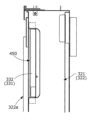
図6に示すように、少なくとも第2電装品箱322は、下部に空気流入部320a、上部に空気流出部320bを備えており、第2送風ファン210bの運転により、空気流入部320aから空気流出部320bに向けて第2電装品箱322内に空気が流れる(図6の矢印参照)。なお、第1電装品箱321側にも下方に空気流入部320a、上方に空気流出部320bが設けられてよい。
As shown in FIG. 6, at least the second
本実施形態において、第1電装品箱321側には、第1送風ファン210a,第2送風ファン210bおよび第1圧縮機351,第2圧縮機352等の運転を制御するための制御部50が設けられている。制御部50には、マイロコンピュータやCPU(中央演算処理ユニット)等が用いられてよい。制御部50は第2電装品箱322側に設けられてもよい。
In this embodiment, a
制御部50は、例えば室内機が設置された空間の温度が設定温度付近に達した場合や、室内機の稼働台数が少なくなった場合には、第1送風ファン210a,第2送風ファン210bのうちのいずれか一方のみを運転する1ファン運転モードに入るが、この1ファン運転モード時、制御部50は常に第2電装品箱322の風上側に当たる送風ファン210bを選択する。
For example, when the temperature of the space in which the indoor unit is installed reaches near the set temperature or when the number of indoor units in operation decreases, the
これにより、第2電装品箱322に集約して配置されたインバータ基板(第1インバータ基板511,第2インバータ基板512)、ファンドライバ基板(第1ファンドライバ基板521,第2ファンドライバ基板522)の裏面にあるヒートシンク54に確実に空気が流れ、それぞれが効果的に冷却される。この場合において、1ファン運転モード時に運転休止側となる第1送風ファン210aのファンドライバ基板521は発熱しないため、第2電装品箱322側ではなく、第1電装品箱321側に設けられてもよい。
This ensures that air flows to the
なお、各発熱部品を有するインバータ基板(第1インバータ基板511,第2インバータ基板512)やファンドライバ基板(第1ファンドライバ基板521,第2ファンドライバ基板522)が第1電装品箱321側に集約して配置される場合には、1ファン運転モード時、第1電装品箱321の風上側の送風ファン210aが選択されることになる。
When the inverter boards (
また、圧縮機は、冷凍機油の偏り防止のため交互に運転する必要がある。そのため、圧縮機を駆動するためのインバータ基板が搭載される基板は、1ファン運転時に運転する送風ファンの直下に配置される必要がある。 In addition, the compressors must be operated alternately to prevent uneven distribution of refrigeration oil. Therefore, the board that mounts the inverter board for driving the compressor must be placed directly below the blower fan that is operating during single fan operation.
電装品箱320内における各基板の配置について、平滑回路基板(第1平滑回路基板531,第2平滑回路基板532)は電装品箱内の上部、インバータ基板(第1インバータ基板511,第2インバータ基板512)およびファンドライバ基板(第1ファンドライバ基板521,第2ファンドライバ基板522)は、それよりも下方に配置されることが好ましい。
Regarding the arrangement of each board within the
このような配置にすることで、インバータ基板(第1インバータ基板511,第2インバータ基板512)と圧縮機(第1圧縮機351,第2圧縮機352)との間の距離がより短くなるため、配線作業が容易になる。また、インバータ基板(第1インバータ基板511,第2インバータ基板512)やファンドライバ基板(第1ファンドライバ基板521,第2ファンドライバ基板522)のヒートシンク54が平滑回路基板(第1平滑回路基板531,第2平滑回路基板532)を冷却して暖められた空気に晒されることもない。従って、、平滑回路基板より発熱量の大きいインバータ基板やファンドライバ基板の冷却を効果的に行うことができる。
By arranging in this way, the distance between the inverter boards (
また、発熱部品による高温領域と、これ以外の低温領域との間に仕切り板を設ける態様も熱の伝搬を防止するうえで有効である。先に説明したように、第1電装品箱321と第2電装品箱322は、センターピラー40により離されており、互いに熱の影響が少なくなる。また、第1電装品箱321の右側面版321Rと第2電装品箱322の左側面版322Lにより距離が離される。これにより、第1電装品箱321と第2電装品箱322の中を流れる風も上下に流れやすくなる。
Providing a partition between the high-temperature area caused by the heat-generating components and the other low-temperature areas is also effective in preventing the propagation of heat. As explained above, the first
《電装品箱の開閉機構(第2実施形態)》
次に、図7ないし図10を参照して、電装品箱320(第1電装品箱321,第2電装品箱322)の開閉機構について説明する。
Opening and closing mechanism for electrical component box (second embodiment)
Next, an opening/closing mechanism for the electrical component box 320 (the first
本実施形態に係る室外機1では、電装品箱320の大型化に伴って、電装品箱320を第1電装品箱321と第2電装品箱322とに分割しているが、筐体10に対する組み立て性(付け外し性)とメンテナンス性を改善するため次の構成を採用している。
In the
先にも説明したように、センターピラー40によって機械室30の正面30aは左側と右側に分けられ、左側の第1電装品箱321は、機械室30の正面30aの左側に配置され、右側の第2電装品箱322は、機械室30の正面30aの右側に配置されるが、第1電装品箱321の右側枠(右辺)321Rおよび第2電装品箱322の左側枠(左辺)322L側がそれぞれヒンジを介してセンターピラー40に開閉可能かつ付け外し可能に連結されている。
As explained above, the front 30a of the
図8および図9に示すように、センターピラー40は、正面部(前面部)40F、左側面部40Lおよび右側面部40Rを含むコ字状の柱でなる。図3を参照して、正面部40Fは機械室30の正面30aに対して所定間隔をもって筐体10の内側に配置されている。すなわち、センターピラー40は、機械室30の正面30aよりも一段奥まった位置に配置されている。
8 and 9, the
これは後述するように、第1電装品箱321と第2電装品箱322とを電気的につなぐ接続配線329(図12参照)を機械室30の正面30aから出っ張らせることなく、センターピラー40の正面部40F側を通すためである。
As described below, this is to allow the connection wiring 329 (see FIG. 12) that electrically connects the first
図10に示すヒンジのうち、第1電装品箱321の右側枠321R側の第1ヒンジ6は、その回転軸(ボス612,632)がセンターピラー40の左側面部40Lの側方(図8において左側)で、かつ、センターピラー40の正面部40Fよりも機械室30の正面30a側寄りの特定された左側の支点位置60aに配置される。
Of the hinges shown in FIG. 10, the
また、第2電装品箱322の左側枠322側に配置される他方の第2ヒンジ7は、その回転軸(ボス712,732)がセンターピラー40の右側面部40Rの側方(図8において右側)で、かつ、センターピラー40の正面部40Fよりも機械室30の正面30a側寄りの特定された右側の支点位置70aに配置される。
The other
第1ヒンジ6の左側の支点位置60aと第2ヒンジ7の右側の支点位置70aは、機械室30の正面30aよりも内側でセンターピラー40を挟んで左右対称である。
The
このように、第1ヒンジ6の左側の支点位置60aと第2ヒンジ7の右側の支点位置70aを特定された位置にすることにより、第1電装品箱321と第2電装品箱322をセンターピラー40により近接させた位置で支障なく開閉することができる。
In this way, by setting the
次に、第1電装品箱321の右側枠321R側の第1ヒンジ6の具体的な構成について説明する。第1ヒンジ6には、第1電装品箱321の右側枠321Rとセンターピラー40の左側面部40Lとの間で、かつその間の上部に配置される第1上ヒンジ6Uと、第1電装品箱321の右側枠321Rとセンターピラー40の左側面部40Lとの間で、かつその間の下部に配置される第1下ヒンジ6Lとが含まれている。
Next, the specific configuration of the
第1上ヒンジ6Uは、雄ヒンジ部61と雌ヒンジ部62の組み合わせからなる。雄ヒンジ部61は、センターピラー40の左側面部40Lから横方向(図8,9において左方向)に向けて水平(筐体10の底板301と平行)に張り出す舌片部611と、舌片部611の上面に垂直に立設された円筒もしくは円柱状のボス612とを備えている。
The first
雌ヒンジ部62は、第1電装品箱321の右側枠321Rから上記舌片部611と重なり合うように水平に張り出すヒンジ片621を有し、ヒンジ片621には上記ボス612に嵌合する軸受孔622が穿設されている。
The
第1下ヒンジ6Lは、雄ヒンジ部63と雌ヒンジ部64の組み合わせからなる。雄ヒンジ部63は、センターピラー40の左側面部40Lから横方向(図8,9において左方向)に向けて水平に張り出す舌片部631と、舌片部631の上面に垂直に立設された円筒もしくは円柱状のボス632とを備えている。
The first
第1上ヒンジ6Uのボス612と第1下ヒンジ6Lのボス632は、ともに同軸として上記左側の支点位置60aに配置されている。
The
雌ヒンジ部64は、第1電装品箱321の右側枠321Rから上記舌片部631と重なり合うように水平に張り出すヒンジ片641を有し、ヒンジ片641には上記ボス632に嵌合する軸受孔642が穿設されている。
The female hinge portion 64 has a
次に、第2電装品箱322の左側枠322L側の第2ヒンジ7について説明する。第2ヒンジ7には、第2電装品箱322の左側枠322Lとセンターピラー40の右側面部40Rとの間で送風機室20側寄りの上部に配置される第2上ヒンジ7Uと、第2電装品箱322の左側枠322Lとセンターピラー40の右側面部40Rとの間で底板301側寄りの下部に配置される第2下ヒンジ7Lとが含まれている。
Next, the
第2上ヒンジ7Uは、雄ヒンジ部71と雌ヒンジ部72の組み合わせからなる。雄ヒンジ部71は、センターピラー40の右側面部40Rから横方向(図8,9において右方向)に向けて水平に張り出す舌片部711と、舌片部711の上面に垂直に立設された円筒もしくは円柱状のボス712とを備えている。
The second
雌ヒンジ部72は、第2電装品箱322の左側枠322Lから上記舌片部711と重なり合うように水平に張り出すヒンジ片721を有し、ヒンジ片721には上記ボス712に嵌合する軸受孔722が穿設されている。
The
第2下ヒンジ7Lは、雄ヒンジ部73と雌ヒンジ部74の組み合わせからなる。雄ヒンジ部73は、センターピラー40の右側面部40Rから横方向(図8,9において右方向)に向けて水平に張り出す舌片部731と、舌片部731の上面に垂直に立設された円筒もしくは円柱状のボス732とを備えている。
The second
第2上ヒンジ7Uのボス712と第2下ヒンジ7Lのボス732、ともに同軸として上記右側の支点位置70aに配置されている。
The
雌ヒンジ部74は、第2電装品箱322の左側枠322Lから上記舌片部731と重なり合うように水平に張り出すヒンジ片741を有し、ヒンジ片741には上記ボス732に嵌合する軸受孔742が穿設されている。
The
本実施形態において、第1上ヒンジ6Uの雄ヒンジ部61と第2上ヒンジ7Uの雄ヒンジ部71は、アタッチメント金具410に一体として形成され、ブラケット411を介してセンターピラー40の正面部40Fに固定される。
In this embodiment, the
また、第1下ヒンジ6Lの雄ヒンジ部63と第2下ヒンジ7Lの雄ヒンジ部73は、アタッチメント金具420に一体として形成され、同アタッチメント金具420を介してセンターピラー40の正面部40Fに固定される。図10において、参照符号421は、電装品箱用のサービスパネル311,312の一部分を係止するための受け金具である。
The
このようなヒンジ(第1ヒンジ6,第2ヒンジ7)を採用することにより、図7に示すように、メンテナンス時に、第1電装品箱321および第2電装品箱322をセンターピラー40側を支点として適宜開くことができる。
By using such hinges (
また、第1電装品箱321を持ち上げて、軸受孔622,642をボス612,632から外すことにより、第1電装品箱321を取り外すことかできる。同様に、第2電装品箱321を取り外すには、第2電装品箱322を持ち上げて、軸受孔722,742をボス712,732から外せばよい。
The first
第1電装品箱321を例にして取付方について説明すると、軸受孔622,642をボス612,632に嵌合させることにより、第1電装品箱321をセンターピラー40に回動可能(開閉可能)に取り付けることができるが、下方のボス632の軸長を上方のボス612の軸長よりも長くすることが好ましい。
To explain the installation method using the first
これによれば、まず、下方の軸受孔642をその相手方のボス632に嵌合させ、その後に上方の軸受孔622をその相手方のボス612に嵌合させる手順となり、上下2つの軸受孔622,642を同時にボス612,632に嵌合させる場合に比べて、嵌合作業が容易となる。
This allows the
《各電装品箱の間に掛け渡される接続配線の引き回し(第3実施形態)》
先に説明したように、電装品箱320が第1電装品箱321と第2第1電装品箱322とに分割されるに伴って、それら第1電装品箱321と第2電装品箱322との間に接続配線が掛け渡されることになるが、その配線作業やメンテナンスの都合上、センターピラー40の正面部40Fに配線経路を確保することが好ましい。そこで、図11ないし図17を参照して、その構成について説明する。
<<Routing of connection wiring between electrical component boxes (third embodiment)>>
As described above, as the
まず、図11に示すように、好ましい態様として、センターピラー40の正面部40Fに幕板430が取り付けられる。幕板430は化粧板を兼ねるが、機械室30の正面30aから見て、左側の第1電装品箱321の右側枠321Rとセンターピラー40の左側面部40Lとの間の隙間G(図8参照)および右側の第2電装品箱322の左側枠322Lとセンターピラー40の右側面部40Rとの間の隙間G(図8参照)を覆い隠す幅を有している。
First, as shown in FIG. 11, in a preferred embodiment, a
次に、電装品箱から接続配線を引き出すにあたって、電装品箱の電装品箱カバーに開口部を設けることは雨水の浸入を許すおそれがあるので、サービスパネル311,312(310)に対向する電装品箱カバーに開口部を設けることは好ましくない。
Next, when pulling out the connection wiring from the electrical equipment box, providing an opening in the electrical equipment box cover of the electrical equipment box may allow rainwater to enter, so it is not preferable to provide an opening in the electrical equipment box cover facing the
そこで、図11および図12に示すように、第1電装品箱321側にはその右側枠321Rに接続配線329の引出部330を形成する。また、第2電装品箱322側にはその左側枠322Lに接続配線329の引出部330を形成する。
As shown in Figures 11 and 12, a pull-out
本実施形態によれば、第1電装品箱321の引出部330をその右側枠321Rの前端側の一部分に形成された切り欠き溝331とし、同様に、第2電装品箱322の引出部330をその左側枠322Lの前端側の一部分に形成された切り欠き溝332としている。
In this embodiment, the pull-out
なお、本実施形態では、切り欠き溝331,332をそれぞれ一つの大きな切り欠きとしているが、図7に示すように、切り欠き溝331,332をそれぞれ2つ形成してもよい。切り欠き溝331,332をいくつ設けるかは任意である。
In this embodiment, each of the
幕板430の正面で、切り欠き溝331,332との間が接続配線329の引き回し部440として用いられる。先に説明したように、センターピラー40はその正面部40Fが機械室30の正面30aよりも筐体10の内側に引っ込められているため、幕板430を設けたとしても、接続配線329を機械室30の正面30aより出っ張らせることなくセンターピラー40の正面部40Fの前方を通すことができる。
The area between the
図13および図14を併せて参照して、配線引き回し部440に配線カバー450が被せられる。配線カバー450は、第1電装品箱321側の切り欠き溝331および第2電装品箱322側の切り欠き溝332を覆う大きさ(切り欠き溝331,332間を跨ぐ大きさ)を有している。
Referring to both Figures 13 and 14, the
本実施形態において、配線カバー450は板金製であるため、その切り口部分によって接続配線329に傷が付かないように、配線カバー450の両端451,451を正面側に折り返して切り口が当たらないようにしている。
In this embodiment, since the
本実施形態によると、図12に示すように、配線引き回し部440に接続配線329の配線押さえ部材411が設けられている。また、図15に示すように、配線カバー450の裏面542側にも接続配線329の配線押さえ部材453が設けられている。配線押さえ部材411,453はスポンジ等の弾性材であることが好ましく、配線カバー450を配線引き回し部440に取り付けるに伴って、配線押さえ部材411,453により接続配線329が挟まれる。なお、配線押さえ部材411,453の一方は省略されてもよい。さらに好ましい態様として、配線カバー450の裏面452側には、結露対策としての断熱材454が設けられている。
According to this embodiment, as shown in FIG. 12, a
図16を併せて参照して、配線引き回し部440において、配線カバー450はその両端451が第1電装品箱321の電装品箱カバー321aと第2電装品箱322の電装品箱カバー322aとによって押さえられ。より密閉性が高められる。
Referring also to FIG. 16, in the
以上説明したように、本第3実施形態によれば、電装品箱がセンターピラーを挟んで第1電装品箱と第2電装品箱の2つに分割される空気調和機の室外機において、各電装品箱間に掛け渡される接続配線をセンターピラーの前側を通すことができるとともに、各電装品箱のセンターピラーと対向する側の側枠に接続配線の引出部を形成したことにより、雨水等の浸入や機外延焼を防止し得る密閉性の高い電装品箱が得られる。 As described above, according to the third embodiment, in an outdoor unit for an air conditioner in which the electrical equipment box is divided into two, a first electrical equipment box and a second electrical equipment box, by a center pillar, the connection wiring that spans between each electrical equipment box can be passed through the front side of the center pillar, and by forming an outlet for the connection wiring on the side frame of each electrical equipment box that faces the center pillar, a highly sealed electrical equipment box that can prevent the intrusion of rainwater, etc. and the spread of fire to the outside of the unit can be obtained.
1 室外機
10 筐体
20 送風機室
210 送風機
220 ファンガード
30 機械室
30a 機械室の正面
310(311~314) サービスパネル
320 電装品箱
321 第1電装品箱
321a 第1電装品箱カバー
322 第2電装品箱
322a 第2電装品箱カバー
329 接続配線
330 引出部
331,332 切り欠き溝
350 熱源部(圧縮機)
351 第1熱源部(第1圧縮機)
352 第2熱源部(第2圧縮機)
40 センターピラー
40F 正面部
40L 左側面部
40R 右側面部
411,453 配線押さえ部材
440 配線引き回し部
450 配線カバー
50 制御部
511,512 インバータ基板
521,522 ファンドライバ基板
531,532 平滑回路基板
54 ヒートシンク
6,7 ヒンジ
6U,7U 上ヒンジ
6L,7L 下ヒンジ
60a,70a 支点位置
61,63,71,73 雄ヒンジ部
62,64,72,74 雌ヒンジ部
612,632,712,732 ボス(回転軸)
622,642,722,742 軸受孔
REFERENCE SIGNS
351 First heat source unit (first compressor)
352 Second heat source unit (second compressor)
Description of the Reference Signs 40:
622, 642, 722, 742 Bearing hole
Claims (3)
上記電装品箱は、上記第1送風ファンの風上側および上記第2送風ファンの風上側に配置され、
上記電装品箱の上記第2送風ファンの風上側に上記制御部の中で冷却が必要なIPMを含む発熱部品が集約して配置され、上記電装品箱の上記第1送風ファンの風上側には上記IPMを含む発熱部品は配置されず、かつ、前記IPMを含まない発熱部品が配置され、
上記2台の送風ファンのうちのいずれか一方のみを運転する1ファン運転時に上記第2送風ファンが運転されることを特徴とする空気調和機の室外機。 The air conditioner includes a housing partitioned into a blower chamber in an upper portion in which at least two blower fans, a first blower fan and a second blower fan, are arranged side by side, and a machine chamber in a lower portion in which a refrigerant circuit including a compressor and a heat exchanger and an electrical equipment box accommodating a control unit that controls operation of at least the compressor and the blower fans are arranged,
the electrical equipment box is disposed on the windward side of the first blower fan and on the windward side of the second blower fan,
heat generating components including an IPM that needs to be cooled in the control unit are collectively arranged on the upwind side of the second blower fan of the electrical equipment box, and heat generating components including the IPM are not arranged on the upwind side of the first blower fan of the electrical equipment box, and heat generating components not including the IPM are arranged,
The outdoor unit of an air conditioner, wherein the second blower fan is operated during single fan operation in which only one of the two blower fans is operated.
3. The outdoor unit of an air conditioner as described in claim 2, characterized in that an air flow path is formed in the second electrical equipment box through which air in the machine room flows from below to above, and air flows from below to above along the substrate surface in the second electrical equipment box as the second blower fan operates.
Priority Applications (1)
| Application Number | Priority Date | Filing Date | Title |
|---|---|---|---|
| JP2020146847A JP7635521B2 (en) | 2020-09-01 | 2020-09-01 | Air conditioner outdoor unit |
Applications Claiming Priority (1)
| Application Number | Priority Date | Filing Date | Title |
|---|---|---|---|
| JP2020146847A JP7635521B2 (en) | 2020-09-01 | 2020-09-01 | Air conditioner outdoor unit |
Publications (2)
| Publication Number | Publication Date |
|---|---|
| JP2022041570A JP2022041570A (en) | 2022-03-11 |
| JP7635521B2 true JP7635521B2 (en) | 2025-02-26 |
Family
ID=80499360
Family Applications (1)
| Application Number | Title | Priority Date | Filing Date |
|---|---|---|---|
| JP2020146847A Active JP7635521B2 (en) | 2020-09-01 | 2020-09-01 | Air conditioner outdoor unit |
Country Status (1)
| Country | Link |
|---|---|
| JP (1) | JP7635521B2 (en) |
Families Citing this family (1)
| Publication number | Priority date | Publication date | Assignee | Title |
|---|---|---|---|---|
| JP2023141084A (en) * | 2022-03-23 | 2023-10-05 | 株式会社富士通ゼネラル | Air conditioner outdoor unit and air conditioner |
Citations (6)
| Publication number | Priority date | Publication date | Assignee | Title |
|---|---|---|---|---|
| JP2009068743A (en) | 2007-09-12 | 2009-04-02 | Sanyo Electric Co Ltd | Air conditioner |
| JP2011127807A (en) | 2009-12-16 | 2011-06-30 | Mitsubishi Electric Corp | Outdoor unit, air conditioner and method of operating the air conditioner |
| JP2018017409A (en) | 2016-07-25 | 2018-02-01 | 株式会社富士通ゼネラル | Air conditioner outdoor unit |
| JP2019158254A (en) | 2018-03-14 | 2019-09-19 | 株式会社富士通ゼネラル | Air conditioner |
| JP2022041569A (en) | 2020-09-01 | 2022-03-11 | 株式会社富士通ゼネラル | Outdoor unit for air conditioner |
| JP2022041571A (en) | 2020-09-01 | 2022-03-11 | 株式会社富士通ゼネラル | Outdoor unit for air conditioner |
Family Cites Families (3)
| Publication number | Priority date | Publication date | Assignee | Title |
|---|---|---|---|---|
| JP2001324174A (en) * | 2000-05-16 | 2001-11-22 | Sanyo Electric Co Ltd | Freezer unit |
| JP2014044007A (en) * | 2012-08-27 | 2014-03-13 | Toshiba Corp | Outdoor unit of air conditioner |
| JP2016161206A (en) * | 2015-02-27 | 2016-09-05 | ダイキン工業株式会社 | Heat source unit of refrigerating device |
-
2020
- 2020-09-01 JP JP2020146847A patent/JP7635521B2/en active Active
Patent Citations (6)
| Publication number | Priority date | Publication date | Assignee | Title |
|---|---|---|---|---|
| JP2009068743A (en) | 2007-09-12 | 2009-04-02 | Sanyo Electric Co Ltd | Air conditioner |
| JP2011127807A (en) | 2009-12-16 | 2011-06-30 | Mitsubishi Electric Corp | Outdoor unit, air conditioner and method of operating the air conditioner |
| JP2018017409A (en) | 2016-07-25 | 2018-02-01 | 株式会社富士通ゼネラル | Air conditioner outdoor unit |
| JP2019158254A (en) | 2018-03-14 | 2019-09-19 | 株式会社富士通ゼネラル | Air conditioner |
| JP2022041569A (en) | 2020-09-01 | 2022-03-11 | 株式会社富士通ゼネラル | Outdoor unit for air conditioner |
| JP2022041571A (en) | 2020-09-01 | 2022-03-11 | 株式会社富士通ゼネラル | Outdoor unit for air conditioner |
Also Published As
| Publication number | Publication date |
|---|---|
| JP2022041570A (en) | 2022-03-11 |
Similar Documents
| Publication | Publication Date | Title |
|---|---|---|
| KR101589027B1 (en) | Outdoor unit of air conditioner | |
| EP3240973B1 (en) | Outdoor unit of air conditioner | |
| US6701738B2 (en) | Wire fixing structure, electrical equipment mount device and air conditioner using the same | |
| JP7615456B2 (en) | Air conditioner outdoor unit | |
| KR20000017506A (en) | Control box for a room air conditioner | |
| EP3126750B1 (en) | Outdoor unit of an air conditioner and method of manufacturing the same | |
| AU733859B2 (en) | Air conditioning unit | |
| EP3882529A1 (en) | Outdoor unit for air conditioner | |
| JP7635521B2 (en) | Air conditioner outdoor unit | |
| JP7683181B2 (en) | Air conditioner outdoor unit | |
| JP6537700B2 (en) | Electrical component module and outdoor unit of air conditioner | |
| JP2003106569A (en) | Outdoor unit of air conditioner | |
| JP5921924B2 (en) | Ice machine | |
| JP7125638B1 (en) | outdoor unit of refrigeration equipment | |
| WO2022202590A1 (en) | Electrical component unit and outdoor unit of refrigerating apparatus | |
| JP6452829B2 (en) | Outdoor unit | |
| JPH11225498A (en) | Pump control panel | |
| JP2004271168A (en) | Outdoor machine of air conditioner | |
| JP2001324174A (en) | Freezer unit | |
| JP4349896B2 (en) | Air conditioner outdoor unit | |
| KR100784767B1 (en) | Air conditioner | |
| JP3139365B2 (en) | Outdoor unit for air conditioner | |
| JPH09292142A (en) | Outdoor unit of air conditioner | |
| CN218627099U (en) | Automatically controlled structure and air condensing units | |
| CN222799247U (en) | Combined air conditioning unit |
Legal Events
| Date | Code | Title | Description |
|---|---|---|---|
| A621 | Written request for application examination |
Free format text: JAPANESE INTERMEDIATE CODE: A621 Effective date: 20230630 |
|
| A977 | Report on retrieval |
Free format text: JAPANESE INTERMEDIATE CODE: A971007 Effective date: 20240215 |
|
| A131 | Notification of reasons for refusal |
Free format text: JAPANESE INTERMEDIATE CODE: A131 Effective date: 20240220 |
|
| A521 | Request for written amendment filed |
Free format text: JAPANESE INTERMEDIATE CODE: A523 Effective date: 20240422 |
|
| A02 | Decision of refusal |
Free format text: JAPANESE INTERMEDIATE CODE: A02 Effective date: 20240730 |
|
| A521 | Request for written amendment filed |
Free format text: JAPANESE INTERMEDIATE CODE: A523 Effective date: 20241022 |
|
| A911 | Transfer to examiner for re-examination before appeal (zenchi) |
Free format text: JAPANESE INTERMEDIATE CODE: A911 Effective date: 20241030 |
|
| A131 | Notification of reasons for refusal |
Free format text: JAPANESE INTERMEDIATE CODE: A131 Effective date: 20241128 |
|
| A521 | Request for written amendment filed |
Free format text: JAPANESE INTERMEDIATE CODE: A523 Effective date: 20241225 |
|
| TRDD | Decision of grant or rejection written | ||
| A01 | Written decision to grant a patent or to grant a registration (utility model) |
Free format text: JAPANESE INTERMEDIATE CODE: A01 Effective date: 20250114 |
|
| A61 | First payment of annual fees (during grant procedure) |
Free format text: JAPANESE INTERMEDIATE CODE: A61 Effective date: 20250127 |
|
| R150 | Certificate of patent or registration of utility model |
Ref document number: 7635521 Country of ref document: JP Free format text: JAPANESE INTERMEDIATE CODE: R150 |
|
| S533 | Written request for registration of change of name |
Free format text: JAPANESE INTERMEDIATE CODE: R313533 |