JP7638246B2 - Battery manufacturing method - Google Patents

Battery manufacturing method Download PDF

Info

Publication number
JP7638246B2
JP7638246B2 JP2022143307A JP2022143307A JP7638246B2 JP 7638246 B2 JP7638246 B2 JP 7638246B2 JP 2022143307 A JP2022143307 A JP 2022143307A JP 2022143307 A JP2022143307 A JP 2022143307A JP 7638246 B2 JP7638246 B2 JP 7638246B2
Authority
JP
Japan
Prior art keywords
separator
adhesive layer
positive electrode
electrode sheet
region
Prior art date
Legal status (The legal status is an assumption and is not a legal conclusion. Google has not performed a legal analysis and makes no representation as to the accuracy of the status listed.)
Active
Application number
JP2022143307A
Other languages
Japanese (ja)
Other versions
JP2024038932A (en
Inventor
泰助 伊勢田
晶 西田
弘二 二本松
Current Assignee (The listed assignees may be inaccurate. Google has not performed a legal analysis and makes no representation or warranty as to the accuracy of the list.)
Prime Planet Energy and Solutions Inc
Original Assignee
Prime Planet Energy and Solutions Inc
Priority date (The priority date is an assumption and is not a legal conclusion. Google has not performed a legal analysis and makes no representation as to the accuracy of the date listed.)
Filing date
Publication date
Application filed by Prime Planet Energy and Solutions Inc filed Critical Prime Planet Energy and Solutions Inc
Priority to JP2022143307A priority Critical patent/JP7638246B2/en
Priority to EP23193202.1A priority patent/EP4336614A3/en
Priority to KR1020230117494A priority patent/KR102888089B1/en
Priority to US18/462,367 priority patent/US20240088448A1/en
Priority to CN202311157338.3A priority patent/CN117673431A/en
Publication of JP2024038932A publication Critical patent/JP2024038932A/en
Application granted granted Critical
Publication of JP7638246B2 publication Critical patent/JP7638246B2/en
Active legal-status Critical Current
Anticipated expiration legal-status Critical

Links

Images

Classifications

    • HELECTRICITY
    • H01ELECTRIC ELEMENTS
    • H01MPROCESSES OR MEANS, e.g. BATTERIES, FOR THE DIRECT CONVERSION OF CHEMICAL ENERGY INTO ELECTRICAL ENERGY
    • H01M10/00Secondary cells; Manufacture thereof
    • H01M10/04Construction or manufacture in general
    • H01M10/0404Machines for assembling batteries
    • HELECTRICITY
    • H01ELECTRIC ELEMENTS
    • H01MPROCESSES OR MEANS, e.g. BATTERIES, FOR THE DIRECT CONVERSION OF CHEMICAL ENERGY INTO ELECTRICAL ENERGY
    • H01M10/00Secondary cells; Manufacture thereof
    • H01M10/04Construction or manufacture in general
    • H01M10/0431Cells with wound or folded electrodes
    • HELECTRICITY
    • H01ELECTRIC ELEMENTS
    • H01MPROCESSES OR MEANS, e.g. BATTERIES, FOR THE DIRECT CONVERSION OF CHEMICAL ENERGY INTO ELECTRICAL ENERGY
    • H01M10/00Secondary cells; Manufacture thereof
    • H01M10/05Accumulators with non-aqueous electrolyte
    • H01M10/058Construction or manufacture
    • H01M10/0587Construction or manufacture of accumulators having only wound construction elements, i.e. wound positive electrodes, wound negative electrodes and wound separators
    • HELECTRICITY
    • H01ELECTRIC ELEMENTS
    • H01MPROCESSES OR MEANS, e.g. BATTERIES, FOR THE DIRECT CONVERSION OF CHEMICAL ENERGY INTO ELECTRICAL ENERGY
    • H01M4/00Electrodes
    • H01M4/02Electrodes composed of, or comprising, active material
    • H01M4/04Processes of manufacture in general
    • H01M4/043Processes of manufacture in general involving compressing or compaction
    • H01M4/0435Rolling or calendering
    • HELECTRICITY
    • H01ELECTRIC ELEMENTS
    • H01MPROCESSES OR MEANS, e.g. BATTERIES, FOR THE DIRECT CONVERSION OF CHEMICAL ENERGY INTO ELECTRICAL ENERGY
    • H01M4/00Electrodes
    • H01M4/02Electrodes composed of, or comprising, active material
    • H01M4/13Electrodes for accumulators with non-aqueous electrolyte, e.g. for lithium-accumulators; Processes of manufacture thereof
    • H01M4/139Processes of manufacture
    • HELECTRICITY
    • H01ELECTRIC ELEMENTS
    • H01MPROCESSES OR MEANS, e.g. BATTERIES, FOR THE DIRECT CONVERSION OF CHEMICAL ENERGY INTO ELECTRICAL ENERGY
    • H01M50/00Constructional details or processes of manufacture of the non-active parts of electrochemical cells other than fuel cells, e.g. hybrid cells
    • H01M50/40Separators; Membranes; Diaphragms; Spacing elements inside cells
    • H01M50/46Separators, membranes or diaphragms characterised by their combination with electrodes
    • H01M50/461Separators, membranes or diaphragms characterised by their combination with electrodes with adhesive layers between electrodes and separators
    • HELECTRICITY
    • H01ELECTRIC ELEMENTS
    • H01MPROCESSES OR MEANS, e.g. BATTERIES, FOR THE DIRECT CONVERSION OF CHEMICAL ENERGY INTO ELECTRICAL ENERGY
    • H01M10/00Secondary cells; Manufacture thereof
    • H01M10/04Construction or manufacture in general
    • H01M10/0404Machines for assembling batteries
    • H01M10/0409Machines for assembling batteries for cells with wound electrodes
    • HELECTRICITY
    • H01ELECTRIC ELEMENTS
    • H01MPROCESSES OR MEANS, e.g. BATTERIES, FOR THE DIRECT CONVERSION OF CHEMICAL ENERGY INTO ELECTRICAL ENERGY
    • H01M10/00Secondary cells; Manufacture thereof
    • H01M10/05Accumulators with non-aqueous electrolyte
    • H01M10/052Li-accumulators
    • H01M10/0525Rocking-chair batteries, i.e. batteries with lithium insertion or intercalation in both electrodes; Lithium-ion batteries
    • YGENERAL TAGGING OF NEW TECHNOLOGICAL DEVELOPMENTS; GENERAL TAGGING OF CROSS-SECTIONAL TECHNOLOGIES SPANNING OVER SEVERAL SECTIONS OF THE IPC; TECHNICAL SUBJECTS COVERED BY FORMER USPC CROSS-REFERENCE ART COLLECTIONS [XRACs] AND DIGESTS
    • Y02TECHNOLOGIES OR APPLICATIONS FOR MITIGATION OR ADAPTATION AGAINST CLIMATE CHANGE
    • Y02EREDUCTION OF GREENHOUSE GAS [GHG] EMISSIONS, RELATED TO ENERGY GENERATION, TRANSMISSION OR DISTRIBUTION
    • Y02E60/00Enabling technologies; Technologies with a potential or indirect contribution to GHG emissions mitigation
    • Y02E60/10Energy storage using batteries
    • YGENERAL TAGGING OF NEW TECHNOLOGICAL DEVELOPMENTS; GENERAL TAGGING OF CROSS-SECTIONAL TECHNOLOGIES SPANNING OVER SEVERAL SECTIONS OF THE IPC; TECHNICAL SUBJECTS COVERED BY FORMER USPC CROSS-REFERENCE ART COLLECTIONS [XRACs] AND DIGESTS
    • Y02TECHNOLOGIES OR APPLICATIONS FOR MITIGATION OR ADAPTATION AGAINST CLIMATE CHANGE
    • Y02PCLIMATE CHANGE MITIGATION TECHNOLOGIES IN THE PRODUCTION OR PROCESSING OF GOODS
    • Y02P70/00Climate change mitigation technologies in the production process for final industrial or consumer products
    • Y02P70/50Manufacturing or production processes characterised by the final manufactured product

Landscapes

  • Chemical & Material Sciences (AREA)
  • Chemical Kinetics & Catalysis (AREA)
  • Electrochemistry (AREA)
  • General Chemical & Material Sciences (AREA)
  • Engineering & Computer Science (AREA)
  • Manufacturing & Machinery (AREA)
  • Materials Engineering (AREA)
  • Secondary Cells (AREA)
  • Electric Double-Layer Capacitors Or The Like (AREA)
  • Cell Separators (AREA)

Description

本開示は、電池の製造方法に関する。 This disclosure relates to a method for manufacturing a battery.

特許第5328034号公報には、セパレータが、当該セパレータが具備する接着性樹脂によって正極シートおよび負極シートのうちの少なくとも一方に接着されて一体化された巻回電極体群が開示されている。かかる巻回電極体群は、予め接着性樹脂が具備されたセパレータを用いて巻回電極体群を形成する工程と、巻回電極体群に加熱プレスを施して、正極シートおよび負極シートのうちの少なくとも一方とセパレータとを一体化する工程とを有する製造方法によって製造することができる旨、記載されている。 Japanese Patent No. 5328034 discloses a wound electrode group in which a separator is bonded and integrated with at least one of a positive electrode sheet and a negative electrode sheet by an adhesive resin contained in the separator. It is described that such a wound electrode group can be manufactured by a manufacturing method including a step of forming a wound electrode group using a separator that is already provided with an adhesive resin, and a step of subjecting the wound electrode group to a hot press to integrate at least one of the positive electrode sheet and the negative electrode sheet with the separator.

特許第5328034号公報Patent No. 5328034

ところで、接着層が具備された巻回電極体を備えた電池を生産性高く得ることができる技術のさらなる開発が求められている。 However, there is a demand for further development of technology that can produce batteries with wound electrodes provided with an adhesive layer with high productivity.

ここで開示される電池の製造方法は、帯状の第1セパレータ、帯状の正極シート、帯状の第2セパレータ、および帯状の負極シートが、巻回軸を中心に所定の巻回方向に巻回された巻回電極体であって、上記正極シートと上記第1セパレータとが第1接着層によって接着され、上記正極シートと上記第2セパレータとが第2接着層によって接着された巻回電極体を備えた電池の製造方法であって、以下の工程:上記第1セパレータの表面に上記第1接着層を形成する、第1形成工程;上記正極シートの表面に上記第2接着層を形成する、第2形成工程;および、上記第1セパレータ、上記正極シート、上記第2セパレータ、および上記負極シートを積層する、積層工程;を包含する電池の製造方法である。かかる電池の製造方法によると、第1形成工程および第2形成工程において、第1接着層および第2接着層を巻回電極体に応じた所望の位置に形成することができる。これによって、接着層が具備された巻回電極体を備えた電池を生産性高く得ることができる。 The method for manufacturing a battery disclosed herein is a method for manufacturing a battery having a wound electrode body in which a strip-shaped first separator, a strip-shaped positive electrode sheet, a strip-shaped second separator, and a strip-shaped negative electrode sheet are wound in a predetermined winding direction around a winding axis, the positive electrode sheet and the first separator are bonded by a first adhesive layer, and the positive electrode sheet and the second separator are bonded by a second adhesive layer, and includes the following steps: a first forming step of forming the first adhesive layer on the surface of the first separator; a second forming step of forming the second adhesive layer on the surface of the positive electrode sheet; and a stacking step of stacking the first separator, the positive electrode sheet, the second separator, and the negative electrode sheet. According to this method for manufacturing a battery, in the first forming step and the second forming step, the first adhesive layer and the second adhesive layer can be formed at desired positions according to the wound electrode body. This makes it possible to obtain a battery having a wound electrode body provided with an adhesive layer with high productivity.

一実施形態に係る電池の製造方法を示すフロー図である。FIG. 2 is a flow diagram showing a method for manufacturing a battery according to an embodiment. 一実施形態に係る電極体製造装置の構成を示す模式図である。FIG. 2 is a schematic diagram showing a configuration of an electrode body manufacturing apparatus according to one embodiment. 一実施形態に係る巻芯による部材の巻き取り方法について説明するための説明図である。1 is an explanatory diagram for explaining a method for winding a member around a winding core according to one embodiment. FIG. 一実施形態に係る巻芯による部材の巻き取り方法について説明するための説明図である。1 is an explanatory diagram for explaining a method for winding a member around a winding core according to one embodiment. FIG. 一実施形態に係る巻芯による部材巻き取り方法について説明するための説明図である。1 is an explanatory diagram for explaining a method for winding a member around a winding core according to one embodiment. FIG. 一実施形態に係る巻芯による部材巻き取り方法について説明するための説明図である。1 is an explanatory diagram for explaining a method for winding a member around a winding core according to one embodiment. FIG. 押圧工程について説明するための説明図である。FIG. 11 is an explanatory diagram for explaining a pressing step. 押圧工程について説明するための説明図である。FIG. 11 is an explanatory diagram for explaining a pressing step. 一実施形態に係る電池を模式的に示す斜視図である。FIG. 1 is a perspective view showing a battery according to an embodiment of the present invention. 図5中のVI-VI線に沿う模式的な縦断面図である。FIG. 6 is a schematic vertical cross-sectional view taken along line VI-VI in FIG. 5 . 図5中のVII-VII線に沿う模式的な縦断面図である。FIG. 7 is a schematic vertical cross-sectional view taken along line VII-VII in FIG. 5 . 図5中のVIII-VIII線に沿う模式的な横断面図である。FIG. 8 is a schematic cross-sectional view taken along line VIII-VIII in FIG. 5 . 封口板に取り付けられた電極体を模式的に示す斜視図である。FIG. 2 is a perspective view showing a schematic view of an electrode body attached to a sealing plate. 正極第2集電体と負極第2集電体が取り付けられた電極体を模式的に示す斜視図である。FIG. 2 is a perspective view showing a schematic diagram of an electrode assembly to which a positive electrode second current collector and a negative electrode second current collector are attached. 一実施形態に係る巻回電極体の構成を示す模式図である。FIG. 2 is a schematic diagram showing the configuration of a wound electrode body according to one embodiment. 一実施形態に係る巻回電極体を展開した状態を示す模式図である。FIG. 2 is a schematic diagram showing a state in which a wound electrode body according to one embodiment is unfolded. 図12の分解図である。FIG. 13 is an exploded view of FIG. 図10のXIV-XIV線に沿う模式的な縦断面図である。FIG. 14 is a schematic vertical cross-sectional view taken along line XIV-XIV in FIG. 10 .

以下、ここで開示される技術のいくつかの実施形態について図面を参照しながら説明する。なお、本明細書において特に言及している事項以外の事柄であって、ここで開示される技術の実施に必要な事柄(例えば、本発明を特徴付けない電池の一般的な構成および製造プロセス)は、当該分野における従来技術に基づく当業者の設計事項として把握され得る。ここで開示される技術は、本明細書に開示されている内容と当該分野における技術常識とに基づいて実施することができる。また、以下の説明は、ここで開示される技術をかかる説明に限定することを意図したものではない。なお、本明細書において範囲を示す「A~B」の表記は、「A以上B以下」の意と共に、「Aを超える」および「B未満」の意を包含するものとする。 Below, some embodiments of the technology disclosed herein are described with reference to the drawings. Note that matters other than those specifically mentioned in this specification and necessary for implementing the technology disclosed herein (for example, the general configuration and manufacturing process of a battery that does not characterize the present invention) can be understood as design matters for a person skilled in the art based on the conventional technology in the field. The technology disclosed here can be implemented based on the contents disclosed in this specification and the technical common sense in the field. Furthermore, the following explanation is not intended to limit the technology disclosed here to such explanation. Note that the notation "A to B" indicating a range in this specification includes the meaning of "A or more and B or less", as well as "greater than A" and "less than B".

なお、本明細書において「電池」とは、電気エネルギーを取り出し可能な蓄電デバイス全般を指す用語であって、一次電池と二次電池とを包含する概念である。また、本明細書において「二次電池」とは、電解質を介して正極シートと負極シートの間で電荷担体が移動することによって繰り返し充放電が可能な蓄電デバイス全般をいう。電解質は、液状電解質(電解液)、ゲル状電解質、固体電解質のいずれであってもよい。かかる二次電池は、リチウムイオン二次電池やニッケル水素電池等のいわゆる蓄電池(化学電池)の他に、電気二重層キャパシタ等のキャパシタ(物理電池)等も包含する。以下では、リチウムイオン二次電池を対象とした場合の実施形態について説明する。また、以下の説明では、第1セパレータ71に形成された接着層を第1接着層81、正極シート22に形成された接着層を第2接着層82と呼称するものとする。 In this specification, the term "battery" refers to any storage device capable of extracting electrical energy, and is a concept that includes primary and secondary batteries. In addition, in this specification, the term "secondary battery" refers to any storage device capable of repeated charging and discharging by the movement of charge carriers between a positive electrode sheet and a negative electrode sheet via an electrolyte. The electrolyte may be any of a liquid electrolyte (electrolytic solution), a gel electrolyte, and a solid electrolyte. Such secondary batteries include so-called storage batteries (chemical batteries) such as lithium ion secondary batteries and nickel hydrogen batteries, as well as capacitors (physical batteries) such as electric double layer capacitors. In the following, an embodiment for a lithium ion secondary battery will be described. In the following description, the adhesive layer formed on the first separator 71 will be referred to as the first adhesive layer 81, and the adhesive layer formed on the positive electrode sheet 22 will be referred to as the second adhesive layer 82.

<電池の製造方法>
先ず、本実施形態に係る電池の製造方法について説明する。図1は、本実施形態に係る電池の製造方法を示すフロー図である。図1に示すように、本実施形態に係る電池の製造方法は、第1セパレータ71の表面に第1接着層81を形成する、第1形成工程(ステップS1);正極シート22の表面に第2接着層82を形成する、第2形成工程(ステップS2);および、第1セパレータ71、正極シート22、第2セパレータ72,および負極シート24を積層する、積層工程(ステップS3);を包含する。ここで、「正極シートの表面」とは、正極活物質層22aの表面であってもよいし、正極集電体22cの表面であってもよい。正極シート22の表面に第1接着層81および/または第2接着層82を備える場合、好ましくは、正極シート22は正極集電体22cの両方の面に正極活物質層22aを備えており、当該正極活物質層22aの表面に第1接着層81および/または第2接着層82が備えられているとよい。なお、ここで開示される電池の製造方法は、任意の段階でさらに他の工程を含んでもよいし、その工程が必須なものとして説明されていなければ適宜削除することも可能である。また、ここで開示される技術の効果が発揮される限りにおいて、工程の順序を入れ替えることもできる。以下、本実施形態に係る電池の製造方法について、電池の製造方法を具現化する電極体製造装置200を交えて説明する。
<Battery manufacturing method>
First, a method for manufacturing a battery according to the present embodiment will be described. FIG. 1 is a flow diagram showing a method for manufacturing a battery according to the present embodiment. As shown in FIG. 1, the method for manufacturing a battery according to the present embodiment includes a first forming step (step S1) of forming a first adhesive layer 81 on the surface of a first separator 71; a second forming step (step S2) of forming a second adhesive layer 82 on the surface of a positive electrode sheet 22; and a lamination step (step S3) of laminating the first separator 71, the positive electrode sheet 22, the second separator 72, and the negative electrode sheet 24. Here, the "surface of the positive electrode sheet" may be the surface of the positive electrode active material layer 22a or the surface of the positive electrode current collector 22c. When the first adhesive layer 81 and/or the second adhesive layer 82 are provided on the surface of the positive electrode sheet 22, preferably, the positive electrode sheet 22 is provided with a positive electrode active material layer 22a on both surfaces of the positive electrode current collector 22c, and the first adhesive layer 81 and/or the second adhesive layer 82 are provided on the surface of the positive electrode active material layer 22a. The manufacturing method of the battery disclosed herein may further include other steps at any stage, and if the step is not described as essential, it can be deleted as appropriate. In addition, the order of the steps can be changed as long as the effect of the technology disclosed herein is exerted. Hereinafter, the manufacturing method of the battery according to this embodiment will be described with reference to an electrode body manufacturing apparatus 200 that embodies the manufacturing method of the battery.

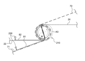
図2は、本実施形態に係る電極体製造装置200の構成を示す模式図である。電極体製造装置200は、帯状の第1セパレータ71と、帯状の正極シート22と、帯状の第2セパレータ72と、帯状の負極シート24とが巻回された巻回電極体であって、正極シート22と第1セパレータ71とが第1接着層81によって接着され、正極シート22と第2セパレータ72とが第2接着層82によって接着された巻回電極体20を製造する装置である。図2に示すように、電極体製造装置200は、巻芯210と、複数のローラ220と、塗布装置230とを備えている。また、電極体製造装置200は、図示されないカッターと、押え治具と、制御装置とを備えている。ここで、カッターは、第1セパレータ71および第2セパレータ72を切断するカッターである。また、押え治具は、第1セパレータ71および第2セパレータ72を巻芯210に押し付ける治具である。電極体製造装置200の各構成要素は、それぞれ所要のアクチュエータを適宜に有している。制御装置は、予め設定されたプログラムに沿って所定のタイミングで所要の動作が実行されるように、電極体製造装置200の各構成要素を制御するように構成されている。制御装置は、例えば、マイクロコントローラのようなコンピュータによって具現化され得る。 2 is a schematic diagram showing the configuration of the electrode body manufacturing apparatus 200 according to this embodiment. The electrode body manufacturing apparatus 200 is an apparatus for manufacturing a wound electrode body 20 in which a strip-shaped first separator 71, a strip-shaped positive electrode sheet 22, a strip-shaped second separator 72, and a strip-shaped negative electrode sheet 24 are wound together, in which the positive electrode sheet 22 and the first separator 71 are bonded by a first adhesive layer 81, and the positive electrode sheet 22 and the second separator 72 are bonded by a second adhesive layer 82. As shown in FIG. 2, the electrode body manufacturing apparatus 200 includes a winding core 210, a plurality of rollers 220, and a coating device 230. The electrode body manufacturing apparatus 200 also includes a cutter (not shown), a pressing tool, and a control device. Here, the cutter is a cutter that cuts the first separator 71 and the second separator 72. The pressing jig is a jig that presses the first separator 71 and the second separator 72 against the winding core 210. Each component of the electrode body manufacturing device 200 has a required actuator as appropriate. The control device is configured to control each component of the electrode body manufacturing device 200 so that a required operation is performed at a specified timing according to a preset program. The control device can be embodied, for example, by a computer such as a microcontroller.

正極シート22と負極シート24と第1セパレータ71と第2セパレータ72とは、それぞれリール(図示省略)などに巻かれた状態で用意されている。正極シート22と負極シート24と第1セパレータ71と第2セパレータ72とは、それぞれ、予め定められた搬送経路k1~k4に沿って搬送される。搬送経路k1は、図示されないリールから巻芯210に向けて正極シート22が送り出される経路である。搬送経路k2は、図示されないリールから巻芯210に向けて負極シート24が送り出される経路である。搬送経路k3は、図示されないリールから巻芯210に向けて第1セパレータ71が送り出される経路である。搬送経路k4は、図示されないリールから巻芯210に向けて第2セパレータ72が送り出される経路である。搬送経路k1~k4には、送り出される正極シート22、負極シート24、第1セパレータ71および第2セパレータ72の緩みを取り除くためのダンサロール機構や、テンションを調整するためのテンションナーなどがそれぞれ適宜に配置されるとよい。 The positive electrode sheet 22, the negative electrode sheet 24, the first separator 71, and the second separator 72 are prepared in a state of being wound on a reel (not shown) or the like. The positive electrode sheet 22, the negative electrode sheet 24, the first separator 71, and the second separator 72 are transported along predetermined transport paths k1 to k4. The transport path k1 is a path along which the positive electrode sheet 22 is sent out from a reel (not shown) toward the winding core 210. The transport path k2 is a path along which the negative electrode sheet 24 is sent out from a reel (not shown) toward the winding core 210. The transport path k3 is a path along which the first separator 71 is sent out from a reel (not shown) toward the winding core 210. The transport path k4 is a path along which the second separator 72 is sent out from a reel (not shown) toward the winding core 210. It is preferable that a dancer roll mechanism for removing slack in the positive electrode sheet 22, negative electrode sheet 24, first separator 71, and second separator 72 being fed, and a tensioner for adjusting the tension are appropriately arranged on each of the conveying paths k1 to k4.

複数のローラ220は、正極シート22、負極シート24、第1セパレータ71および第2セパレータ72の搬送経路k1~k4にそれぞれ配置されている。複数のローラ220は、搬送装置の一例である。複数のローラ220は、各搬送経路k1~k4を定めるために所定位置に配置されている。正極シート22、負極シート24、第1セパレータ71および第2セパレータ72は、それぞれ、複数のローラ220によって搬送される。 The multiple rollers 220 are arranged on the transport paths k1 to k4 of the positive electrode sheet 22, the negative electrode sheet 24, the first separator 71, and the second separator 72, respectively. The multiple rollers 220 are an example of a transport device. The multiple rollers 220 are arranged at predetermined positions to define each of the transport paths k1 to k4. The positive electrode sheet 22, the negative electrode sheet 24, the first separator 71, and the second separator 72 are each transported by the multiple rollers 220.

巻芯210は、側周面に巻き付けられる第1セパレータ71および第2セパレータ72を保持する機能を有する。巻芯210はここでは略円筒状の部材であるが、扁平な形状に巻回する場合には、扁平な巻芯が用いられてもよい。巻芯210としては、ここでは径方向に沿って分割された巻芯を用いているが、分割されていない巻芯を用いてもよいし、径が可変である巻芯を用いてもよい。巻芯210は、第1スリットSaおよび第2スリットSbを有している。第1スリットSaおよび第2スリットSbは、ここでは巻芯210の回転方向に沿って180°離れた位置に配置されている。第1スリットSaに第1セパレータ71の先端を挟み込み、第2スリットSbに第2セパレータ72の先端を挟み込むことによって、各セパレータを巻芯210に固定することができる。 The winding core 210 has a function of holding the first separator 71 and the second separator 72 wound around the side peripheral surface. The winding core 210 is an approximately cylindrical member here, but a flat winding core may be used when winding into a flat shape. A winding core divided along the radial direction is used as the winding core 210 here, but an undivided winding core or a winding core with a variable diameter may be used. The winding core 210 has a first slit Sa and a second slit Sb. The first slit Sa and the second slit Sb are arranged at positions 180° apart along the rotation direction of the winding core 210 here. Each separator can be fixed to the winding core 210 by sandwiching the tip of the first separator 71 in the first slit Sa and the tip of the second separator 72 in the second slit Sb.

また、巻芯210は、さらに吸引孔や溝等を有していてもよい。吸引孔は、側周面に巻き付けられる第1セパレータ71や第2セパレータ72を吸着させるための孔である。吸引孔の平面視における形状は、円形状であってもよいし、方形状であってもよい。あるいは、吸引孔は、スリット状であってもよい。吸引孔は、典型的には、巻芯210の内部に形成され吸引孔に通じた流路である吸引流路を備えている。吸引経路は、吸引孔に負圧を形成するための流路である。吸引経路は、例えば、外部に設置される真空ラインに適宜に接続されて負圧が形成されるように構成されているとよい。そして、溝は、第1セパレータ71および第2セパレータ72が切断される際に、カッターの刃が降ろされる受け部として機能し得る。これにより、巻芯210とカッターの刃が接触することにより、巻芯またはカッターが損傷することを抑制する。 The winding core 210 may further have a suction hole, a groove, or the like. The suction hole is a hole for adsorbing the first separator 71 and the second separator 72 wound around the side peripheral surface. The shape of the suction hole in a plan view may be circular or rectangular. Alternatively, the suction hole may be slit-shaped. The suction hole typically has a suction flow path that is a flow path formed inside the winding core 210 and connected to the suction hole. The suction path is a flow path for forming negative pressure in the suction hole. The suction path may be configured to be appropriately connected to a vacuum line installed outside, for example, so that negative pressure is formed. The groove can function as a receiving portion for lowering the blade of the cutter when the first separator 71 and the second separator 72 are cut. This prevents the winding core or the cutter from being damaged by contact between the winding core 210 and the blade of the cutter.

塗布装置230は、第1セパレータ71および正極シート22の表面に、搬送方向に沿ってバインダー液(接着剤)を付与する装置である。塗布装置230は、バインダー液を第1セパレータ71および正極シート22の所望の領域に所望の量だけ塗布することができるように構成されている。バインダー液は、例えば後述するような接着層バインダーと、溶媒とを含む。バインダー液の溶媒としては、環境負荷を軽減するとの観点において、いわゆる水系の溶媒が好適に用いられる。この場合、水または水を主体とする混合溶媒を用いることができる。かかる混合溶媒を構成する水以外の溶媒成分としては、水と均一に混合し得る有機溶媒(低級アルコール、低級ケトン等)の一種または二種以上を適宜選択して用いることができる。例えば、水系溶媒の80質量%以上(より好ましくは90質量%以上、さらに好ましくは95質量%以上)が水である水系溶媒の使用が好ましい。特に好ましい例として、実質的に水からなる水系溶媒が挙げられる。また、バインダー液の溶媒は、いわゆる水系の溶媒に限定されず、いわゆる有機溶剤系であってもよい。有機溶剤系溶媒としては、例えばN-メチルピロリドンなどが挙げられる。例えばバインダー液の好適例としては、水を溶媒とし、バインダーとしてのアクリル樹脂(例えば、ポリメタクリル酸エステル樹脂)を混ぜるとよい。なお、バインダー液は、ここに開示される技術の効果を妨げない限り、正極シート22やセパレータに対する濡れ性を改善する目的などで、公知の増粘剤や界面活性剤などの添加剤を1種または2種以上含むことができる。 The coating device 230 is a device that applies a binder liquid (adhesive) to the surfaces of the first separator 71 and the positive electrode sheet 22 along the conveying direction. The coating device 230 is configured to be able to apply the binder liquid in a desired amount to a desired area of the first separator 71 and the positive electrode sheet 22. The binder liquid includes, for example, an adhesive layer binder as described later and a solvent. As the solvent for the binder liquid, a so-called aqueous solvent is preferably used from the viewpoint of reducing the environmental load. In this case, water or a mixed solvent mainly composed of water can be used. As the solvent component other than water that constitutes such a mixed solvent, one or more organic solvents (lower alcohols, lower ketones, etc.) that can be mixed uniformly with water can be appropriately selected and used. For example, it is preferable to use an aqueous solvent in which 80 mass% or more (more preferably 90 mass% or more, even more preferably 95 mass% or more) of the aqueous solvent is water. A particularly preferable example is an aqueous solvent that is essentially composed of water. In addition, the solvent of the binder liquid is not limited to so-called aqueous solvents, and may be so-called organic solvents. Examples of organic solvents include N-methylpyrrolidone. For example, a suitable example of the binder liquid is one in which water is used as the solvent and an acrylic resin (e.g., polymethacrylic acid ester resin) is mixed as the binder. In addition, the binder liquid may contain one or more additives such as known thickeners and surfactants for the purpose of improving the wettability of the positive electrode sheet 22 and the separator, as long as the effect of the technology disclosed herein is not hindered.

塗布装置230としては、例えばインクジェット印刷、グラビアロールコーター、スプレーコーター等の各種の凹版印刷機、スリットコーター、コンマコーター、キャップコーター(Capillary Coater:CAPコーター)等のダイコーター、リップコーター、カレンダー機等の各種の塗布装置を使用することができる。 As the coating device 230, various coating devices can be used, such as inkjet printing, various intaglio printing machines such as gravure roll coaters and spray coaters, die coaters such as slit coaters, comma coaters and cap coaters (Capillary Coaters), lip coaters, calendar machines, etc.

図2に示すように、本実施形態では、巻芯210の巻回中心Oを通過し鉛直方向に延びる鉛直直線lに対する一方側に、第1セパレータ71における正極シート22の対向面上に第1接着層81を形成する形成エリアと、正極シート22の表面上に第2接着層82を形成する形成エリアと、が設けられている(図2のArea1を参照)。このように、接着層形成領域を別々に設けることによって、塗布装置のスペースを小さくすることができるため好ましい。また、Area1において正極シート22は第1セパレータ71の上方に配置されており、Area2において負極シート24は第2セパレータ72の下方に配置されている。 As shown in Fig. 2, in this embodiment, a formation area for forming a first adhesive layer 81 on the surface of the first separator 71 facing the positive electrode sheet 22 and a formation area for forming a second adhesive layer 82 on the surface of the positive electrode sheet 22 are provided on one side of a vertical line l1 that passes through the winding center O of the winding core 210 and extends in the vertical direction (see Area 1 in Fig. 2). By providing the adhesive layer formation areas separately in this manner, the space required for the coating device can be reduced, which is preferable. In Area 1, the positive electrode sheet 22 is disposed above the first separator 71, and in Area 2, the negative electrode sheet 24 is disposed below the second separator 72.

特に限定されるものではないが、巻芯210の巻回中心Oを通過し水平方向に延びる直線lに対する第1セパレータ71における接着層形成領域(換言すると、搬送経路k3)のなす角度θk3は、第1セパレータ71の幅方向における塗りムラ等を改善し、より均一に接着層を形成するこという観点から、好ましくは-30°~+30°であり、より好ましくは-15°~+15°である。また、同様の観点から、直線lと平行な位置に存在する直線lに対する正極シート22における接着層形成領域(換言すると、搬送経路k1)のなす角度θk1は、好ましくは-30°~+30°であり、より好ましくは-15°~+15°である。なお、例えば本実施形態では、θk1およびθk3を-30°程度としている。 Although not particularly limited, the angle θ k3 of the adhesive layer formation region of the first separator 71 (in other words, the conveying path k3) with respect to the straight line l 2 that passes through the winding center O of the winding core 210 and extends in the horizontal direction is preferably −30° to +30°, more preferably −15° to +15°, from the viewpoint of improving coating unevenness in the width direction of the first separator 71 and forming an adhesive layer more uniformly. Also, from the same viewpoint, the angle θ k1 of the adhesive layer formation region of the positive electrode sheet 22 (in other words, the conveying path k1) with respect to the straight line l 3 that exists in a position parallel to the straight line l 2 is preferably −30° to +30°, more preferably −15° to +15°. For example, in this embodiment, θ k1 and θ k3 are set to about −30°.

図3A~図3Dは、本実施形態に係る巻芯210による部材の巻き取り方法について説明するための説明図である。ここで、図3A~図3D中の矢印は巻芯210の回転方向を示しているが、巻芯210の回転方向をかかる方向に限定することを意図したものではない。また、図中の星印は、巻芯210の回転態様を分かり易くするために付与している。そして、図中では、見易くするために正極タブ22tおよび負極タブ24tの記載を省略している。 Figures 3A to 3D are explanatory diagrams for explaining the method of winding a member using the winding core 210 according to this embodiment. Here, the arrows in Figures 3A to 3D indicate the rotation direction of the winding core 210, but are not intended to limit the rotation direction of the winding core 210 to this direction. Also, the star marks in the figures are added to make the rotation mode of the winding core 210 easier to understand. Also, in the figures, the positive electrode tab 22t and the negative electrode tab 24t have been omitted for ease of viewing.

先ず、図3Aに示すように、第1セパレータ71の先端(換言すると、第1セパレータの巻き始め端部71a)を第1スリットSaに挟み込み、第2セパレータ72の先端(換言すると、第2セパレータの巻き始め端部72a)を第2スリットSbに挟み込む。なお、本実施形態では、第1スリットSaおよび第2スリットSbは静電チャックとしての機能を有しており、これによって第1セパレータ71の先端および第2セパレータ72の先端を巻芯210に固定している。かかる構成によると、第1セパレータ71の先端および第2セパレータ72の先端に挟持痕等が生じることを防止することができるため、好ましい。 First, as shown in FIG. 3A, the tip of the first separator 71 (in other words, the winding start end 71a of the first separator) is sandwiched in the first slit Sa, and the tip of the second separator 72 (in other words, the winding start end 72a of the second separator) is sandwiched in the second slit Sb. In this embodiment, the first slit Sa and the second slit Sb function as electrostatic chucks, thereby fixing the tip of the first separator 71 and the tip of the second separator 72 to the winding core 210. This configuration is preferable because it can prevent the tip of the first separator 71 and the tip of the second separator 72 from being pinched.

続いて、図3Bに示すように、巻芯210を矢印方向に略半周回転させることによって、巻芯210に第1セパレータ71と第2セパレータ72とを当接させ、巻芯210に第1セパレータ71と第2セパレータ72とを巻き付ける。図3Bに示すように、本実施形態では、第1セパレータ71を、第1スリットSaの側壁および巻芯210の略半周分の側面において巻芯210に当接させている(図3Bの第1当接領域A1を参照)。また、第2セパレータ72を、第2スリットSbの側壁および巻芯210の略半周分の側面において巻芯210に当接させている(図3Bの第2当接領域A2を参照)。 Next, as shown in FIG. 3B, the winding core 210 is rotated approximately half a circumference in the direction of the arrow to bring the first separator 71 and the second separator 72 into contact with the winding core 210, and the first separator 71 and the second separator 72 are wound around the winding core 210. As shown in FIG. 3B, in this embodiment, the first separator 71 is in contact with the winding core 210 at the side wall of the first slit Sa and approximately half the circumference of the side surface of the winding core 210 (see the first contact area A1 in FIG. 3B). Also, the second separator 72 is in contact with the winding core 210 at the side wall of the second slit Sb and approximately half the circumference of the side surface of the winding core 210 (see the second contact area A2 in FIG. 3B).

次に、図3Cに示すように、巻芯210に巻き取られた第1セパレータ71と供給される第2セパレータ72との間に負極シート24を挟み込む。続いて、図3Dに示すように、巻芯210を略半周回転させた後、巻芯210に巻き取られた第2セパレータ72と供給される第1セパレータ71との間に正極シート22を挟み込む。そして、塗布装置230による第1セパレータ71の表面への第1接着層81の形成と、塗布装置230による正極シート22の表面への第2接着層82の形成とを開始する(第1形成工程,第2形成工程)そして、巻芯210を矢印方向に回転させることによって、第1セパレータ71、正極シート22、第2セパレータ72、および負極シート24を積層する(積層工程)。かかる積層工程は、巻回工程であることが好ましい。そして、各部材を、予め定められた巻き取り数に至るまで巻芯210に巻き取る。以上のようにして、正極シート22と第1セパレータ71とが第1接着層81によって接着され、正極シート22と第2セパレータ72とが第2接着層82によって接着された巻回体20aを得ることができる。 Next, as shown in FIG. 3C, the negative electrode sheet 24 is sandwiched between the first separator 71 wound around the winding core 210 and the second separator 72 to be supplied. Then, as shown in FIG. 3D, after rotating the winding core 210 by approximately half a turn, the positive electrode sheet 22 is sandwiched between the second separator 72 wound around the winding core 210 and the first separator 71 to be supplied. Then, the application device 230 starts forming the first adhesive layer 81 on the surface of the first separator 71 and the application device 230 starts forming the second adhesive layer 82 on the surface of the positive electrode sheet 22 (first formation process, second formation process). Then, the winding core 210 is rotated in the direction of the arrow to stack the first separator 71, the positive electrode sheet 22, the second separator 72, and the negative electrode sheet 24 (stacking process). This stacking process is preferably a winding process. Then, each member is wound around the winding core 210 until a predetermined number of windings is reached. In this manner, a wound body 20a can be obtained in which the positive electrode sheet 22 and the first separator 71 are bonded together by the first adhesive layer 81, and the positive electrode sheet 22 and the second separator 72 are bonded together by the second adhesive layer 82.

図3Cに示すように、本実施形態では、第1セパレータ71を巻芯210に略半周分だけ巻き付けたタイミングで負極シート24を挟み込んでいるが、これに限定されない。例えば、他の実施形態では、巻回体20aを巻芯210から抜き取り易くする等の観点から、第1セパレータ71を第1スリットSaの側壁および巻芯210の略1周部分に巻き付けたタイミングで負極シート24を挟み込んでもよい。ただし、これらはあくまでも一例であって、負極シート24を挟み込むタイミングは、製造する巻回電極体の種類等に応じて適宜調整することができる。 As shown in FIG. 3C, in this embodiment, the negative electrode sheet 24 is sandwiched when the first separator 71 is wound around the winding core 210 by approximately half a circumference, but this is not limited to this. For example, in other embodiments, from the viewpoint of making it easier to remove the wound body 20a from the winding core 210, the negative electrode sheet 24 may be sandwiched when the first separator 71 is wrapped around the side wall of the first slit Sa and approximately one circumference of the winding core 210. However, these are merely examples, and the timing of sandwiching the negative electrode sheet 24 can be adjusted as appropriate depending on the type of wound electrode body to be manufactured, etc.

特に限定されるものではないが、第1形成工程において、第1セパレータ71における第1接着層81の形成開始位置は、正極シート22を挟みこむ位置と同じ位置であってもよいし、正極シート22を挟みこむ位置よりも第1セパレータの巻き始め端部71a側に近い位置(例えば、第1セパレータの巻き始め端部71a側に10mmの位置や20mmの位置)であってもよい。かかる構成によると、第1セパレータ71における正極シート22と対向する領域により確実に第1接着層81を形成することができるため、好ましい。なお、本実施形態では、第1形成工程において、第1セパレータ71における第1接着層81の形成開始位置を、正極シート22を挟みこむ位置よりも第1セパレータの巻き始め端部71a側に近い位置としている(図13および図14を参照)。 Although not particularly limited, in the first forming step, the formation start position of the first adhesive layer 81 on the first separator 71 may be the same position as the position where the positive electrode sheet 22 is sandwiched, or may be a position closer to the winding start end 71a of the first separator than the position where the positive electrode sheet 22 is sandwiched (for example, a position 10 mm or 20 mm toward the winding start end 71a of the first separator). With this configuration, the first adhesive layer 81 can be formed more reliably in the area of the first separator 71 facing the positive electrode sheet 22, which is preferable. In this embodiment, in the first forming step, the formation start position of the first adhesive layer 81 on the first separator 71 is a position closer to the winding start end 71a of the first separator than the position where the positive electrode sheet 22 is sandwiched (see Figures 13 and 14).

特に限定されるものではないが、第1セパレータ71における第1接着層81の形成終了位置は、第1セパレータ71における正極シートの巻き終わり端部22Tと対向する位置であってもよいし、第1セパレータ71における正極シートの巻き終わり端部22Tと対向する位置よりも第1セパレータの巻き終わり端部71b側に近い位置(例えば、第1セパレータの巻き終わり端部71b側に10mmの位置や20mmの位置)であってもよい。かかる構成によると、第1セパレータ71における正極シート22と対向する領域により確実に第1接着層81を形成することができるため、好ましい。なお、本実施形態では、第1セパレータ71における第1接着層81(ここでは、第1接着層81a)の形成終了位置を、第1セパレータ71における正極シートの巻き終わり端部22Tと対向する位置よりも第1セパレータの巻き終わり端部71b側に近い位置としている(図13および図14を参照)。また、本実施形態では、さらに第1セパレータにおける巻き終わり端部71b近傍に第1接着層81bを形成している(図13および図14を参照)。 Although not particularly limited, the end position of the formation of the first adhesive layer 81 in the first separator 71 may be a position facing the end end 22T of the positive electrode sheet in the first separator 71, or may be a position closer to the end end 71b of the first separator than the position facing the end end 22T of the positive electrode sheet in the first separator 71 (for example, a position 10 mm or 20 mm toward the end end 71b of the first separator). According to such a configuration, the first adhesive layer 81 can be formed more reliably in the region facing the positive electrode sheet 22 in the first separator 71, which is preferable. In this embodiment, the end position of the formation of the first adhesive layer 81 (here, the first adhesive layer 81a) in the first separator 71 is closer to the end end 71b of the first separator than the position facing the end end 22T of the positive electrode sheet in the first separator 71 (see Figures 13 and 14). In this embodiment, a first adhesive layer 81b is also formed near the end 71b of the first separator (see Figures 13 and 14).

ここで開示される電池の製造方法によると、第1形成工程および第2形成工程において、それぞれ第1セパレータ71の片面に第1接着層81を形成し、正極シート22の片面に第2接着層82を形成している。かかる構成の電池の製造方法によると、例えばローラ220に接着層が付着することを好適に抑制することができる。これによって、ローラ220に付着した接着層に起因して、第1セパレータ71や正極シート22の搬送が阻害されない。このため、巻回電極体20の連続した生産が阻害されず、巻回電極体20の歩留まりが低下するのを好適に抑制することができる。これによって、接着層が具備されたセパレータを含む巻回電極体20を備えた電池100を生産性高く得ることができる。また、ローラ220によって形成された接着層が損傷しにくくなるため、好ましい。なお、本実施形態では、第1形成工程および第2形成工程を同時に実施しているが、これに限定されず、いずれか一方の工程を先に実施し、他方の工程を後に実施してもよい。 According to the battery manufacturing method disclosed herein, in the first forming step and the second forming step, the first adhesive layer 81 is formed on one side of the first separator 71, and the second adhesive layer 82 is formed on one side of the positive electrode sheet 22. According to the battery manufacturing method having such a configuration, for example, the adhesion of the adhesive layer to the roller 220 can be preferably suppressed. As a result, the conveyance of the first separator 71 and the positive electrode sheet 22 is not hindered due to the adhesive layer attached to the roller 220. Therefore, the continuous production of the wound electrode body 20 is not hindered, and the yield of the wound electrode body 20 can be preferably suppressed from decreasing. As a result, the battery 100 including the wound electrode body 20 including the separator provided with the adhesive layer can be obtained with high productivity. In addition, the adhesive layer formed by the roller 220 is less likely to be damaged, which is preferable. In this embodiment, the first forming step and the second forming step are performed simultaneously, but this is not limited to this, and one of the steps may be performed first and the other step may be performed later.

ここで開示される電池の製造方法では、積層工程において、第1セパレータ71、正極シート22、第2セパレータ72、および負極シート24を搬送し、所定の順番で重ねつつ巻回してもよい。また、第1形成工程において、積層工程で搬送されている第1セパレータ71の正極シート22に重ねられる側の表面に第1接着層81を形成してもよい。そして、第2形成工程において、積層工程で搬送されている正極シート22の第2セパレータ72に重ねられる側の表面に第2接着層82を形成してもよい。かかる構成の電池の製造方法によると、接着層の形成後に、第1セパレータ71および正極シート22をリールに巻き取らなくても良いため、形成した接着層の意図しない接着等を好適に抑制することができるため、好ましい。 In the battery manufacturing method disclosed herein, in the lamination process, the first separator 71, the positive electrode sheet 22, the second separator 72, and the negative electrode sheet 24 may be transported and wound while being stacked in a predetermined order. In addition, in the first formation process, a first adhesive layer 81 may be formed on the surface of the first separator 71 being transported in the lamination process that is to be stacked on the positive electrode sheet 22. Then, in the second formation process, a second adhesive layer 82 may be formed on the surface of the positive electrode sheet 22 being transported in the lamination process that is to be stacked on the second separator 72. According to the battery manufacturing method having such a configuration, since it is not necessary to wind the first separator 71 and the positive electrode sheet 22 on a reel after the adhesive layer is formed, unintended adhesion of the formed adhesive layer can be suitably suppressed, which is preferable.

好適な一態様では、積層工程の直前に接着層形成工程(ここでは、第1形成工程および第2形成工程)を実施する。換言すると、セパレータが展開された状態で、接着層形成工程と積層工程とを連続して実施することが好ましい。かかる構成の電池の製造方法によると、接着層の形成位置をより好適にコントロールすることができるため、巻回電極体20においてより適切な位置に接着層を配置することができる。ここで、接着層を形成する位置(ここでは、塗布装置230が存在する位置)と巻芯210の位置との距離は、例えば50m未満であり、10m未満であってもよいし、3m未満であってもよい。また、接着層形成工程が終了してから積層工程が開始されるまでの時間は、例えば60分未満であり、20分未満であってもよく、5分未満であってもよい。なお、上述した距離や時間は、実際の実施態様に合わせて適宜変更され得る。 In a preferred embodiment, the adhesive layer forming process (here, the first forming process and the second forming process) is performed immediately before the lamination process. In other words, it is preferable to perform the adhesive layer forming process and the lamination process consecutively with the separator unfolded. According to the manufacturing method of the battery having such a configuration, the position where the adhesive layer is formed can be more suitably controlled, so that the adhesive layer can be arranged at a more appropriate position in the wound electrode body 20. Here, the distance between the position where the adhesive layer is formed (here, the position where the coating device 230 is present) and the position of the winding core 210 is, for example, less than 50 m, may be less than 10 m, or may be less than 3 m. In addition, the time from the end of the adhesive layer forming process to the start of the lamination process is, for example, less than 60 minutes, may be less than 20 minutes, or may be less than 5 minutes. The above-mentioned distance and time can be appropriately changed according to the actual embodiment.

ここで開示される電池の製造方法では、第1形成工程において、第1セパレータの巻き始め端部71a近傍の予め定められた第1領域において、第1接着層81が形成されていない領域、および/または、第1セパレータ71において正極シート22と対向する領域に形成された第1接着層81の目付よりも目付の小さい第1接着層81が形成された領域を形成してもよい。つまり、ここで開示される電池の製造方法では、第1領域全体に第1接着層81を形成してもよいし、第1領域全体に第1接着層81を形成してもよい。あるいは、第1領域において第1接着層81が形成されていない領域と第1接着層81を形成してもよい。なお、「第1セパレータの巻き始め端部近傍の第1領域」とは、巻芯210の最内周の長さを100%としたとき、第1セパレータの巻き始め端部71aから例えば50%までの領域であり、100%までの領域、120%までの領域、150%までの領域、200%までの領域であってもよい。あるいは、巻回電極体20の最内周の長さを100%としたとき、第1セパレータの巻き始め端部71aから例えば50%までの領域であり、100%までの領域、120%までの領域、150%までの領域、200%までの領域であってもよい。例えば、本実施形態では、第1セパレータの巻き始め端部71a近傍は、第1セパレータの巻き始め端部71aから2cm以内の領域としている。ただし、これらに限られるものではない。また、「目付」(目付量)とは、接着層の質量を形成領域の面積で割った値(接着層の質量/形成領域の面積)をいう。 In the battery manufacturing method disclosed here, in the first formation step, a region where the first adhesive layer 81 is not formed and/or a region where the first adhesive layer 81 is formed with a smaller basis weight than the basis weight of the first adhesive layer 81 formed in the region of the first separator 71 facing the positive electrode sheet 22 may be formed in a predetermined first region near the winding start end 71a of the first separator. That is, in the battery manufacturing method disclosed here, the first adhesive layer 81 may be formed in the entire first region, or the first adhesive layer 81 may be formed in the entire first region. Alternatively, the first adhesive layer 81 may be formed in the region where the first adhesive layer 81 is not formed in the first region and in the first region. Note that the "first region near the winding start end of the first separator" refers to a region from the winding start end 71a of the first separator to, for example, 50% when the length of the innermost circumference of the winding core 210 is 100%, and may also be a region up to 100%, a region up to 120%, a region up to 150%, or a region up to 200%. Alternatively, when the length of the innermost circumference of the wound electrode body 20 is taken as 100%, it may be, for example, a region from the winding start end 71a of the first separator to 50%, or may be a region from 100%, 120%, 150%, or 200%. For example, in this embodiment, the vicinity of the winding start end 71a of the first separator is a region within 2 cm from the winding start end 71a of the first separator. However, this is not limited to these. In addition, "basis weight" (basis weight amount) refers to the value obtained by dividing the mass of the adhesive layer by the area of the formation area (mass of the adhesive layer / area of the formation area).

かかる構成の電池の製造方法によると、第1セパレータの巻き始め端部71a近傍において、第1接着層81が形成されていないか、形成される第1接着層81の目付が小さい。このため、巻芯210に付着する第1接着層81の量が好適に抑制される。これにより、巻芯210に第1接着層81が付着してもその量が少ない。そして、巻芯210に付着した第1接着層81に起因して、巻回電極体20の連続した生産が阻害されず、巻回電極体20の歩留まりが低下するのを好適に抑制することができる。これによって、接着層が具備されたセパレータを含む巻回電極体20を備えた電池100をより生産性高く得ることができる。 According to the manufacturing method of the battery having such a configuration, the first adhesive layer 81 is not formed near the winding start end 71a of the first separator, or the basis weight of the first adhesive layer 81 formed is small. Therefore, the amount of the first adhesive layer 81 attached to the winding core 210 is suitably suppressed. As a result, even if the first adhesive layer 81 is attached to the winding core 210, the amount is small. And, the continuous production of the wound electrode body 20 is not hindered due to the first adhesive layer 81 attached to the winding core 210, and a decrease in the yield of the wound electrode body 20 can be suitably suppressed. As a result, the battery 100 including the wound electrode body 20 including the separator provided with the adhesive layer can be obtained with higher productivity.

特に限定されるものではないが、第1形成工程において第1領域に第1接着層81を形成する場合、正極シート22と対向する領域における第1接着層81の目付Aに対する、第1領域における第1接着層81の目付Bの比(B/A)は、例えば0.9以下であり、巻芯に付着し得る第1接着層81の量を好適に制御するという観点から、好ましくは0.8以下であり、より好ましくは0.5以下であり、特に好ましくは0.3以下であり、例えば0.1以下であってもよい。 Although not particularly limited, when the first adhesive layer 81 is formed in the first region in the first formation step, the ratio (B/A) of the basis weight B of the first adhesive layer 81 in the first region to the basis weight A of the first adhesive layer 81 in the region facing the positive electrode sheet 22 is, for example, 0.9 or less, and from the viewpoint of appropriately controlling the amount of the first adhesive layer 81 that can adhere to the winding core, is preferably 0.8 or less, more preferably 0.5 or less, and particularly preferably 0.3 or less, and may be, for example, 0.1 or less.

なお、本実施形態では、第1形成工程において、第1セパレータの巻き始め端部71a近傍の予め定められた第1領域(ここでは、第1当接領域A1および後述する領域A3)において、第1接着層81が形成されていない領域を形成している。 In this embodiment, in the first formation process, a region where the first adhesive layer 81 is not formed is formed in a predetermined first region (here, the first contact region A1 and the region A3 described below) near the winding start end 71a of the first separator.

また、図3Dに示すように、本実施形態では、第1セパレータ71と巻芯210との間に第2セパレータ72が配置された領域が形成されている。換言すると、本実施形態では、第1セパレータ71において、第1当接領域A1以外の領域まで延びて、第1接着層81が形成されていない領域(図3Dの領域A3を参照)を形成している。 As shown in FIG. 3D, in this embodiment, a region in which the second separator 72 is disposed is formed between the first separator 71 and the winding core 210. In other words, in this embodiment, the first separator 71 extends to a region other than the first contact region A1 to form a region in which the first adhesive layer 81 is not formed (see region A3 in FIG. 3D).

即ち、ここで開示される電池の製造方法では、第1セパレータ71において、第1当接領域(ここでは、第1当接領域A1)以外の領域まで延びて第1領域を形成してもよい。かかる構成の電池の製造方法によると、接着層が具備された巻回電極体20を備えた電池100の生産性の向上に加えて、第1セパレータ71への第1接着層81の過度な形成を抑制することができ、これによって、電池100の抵抗増大の抑制や巻回電極体20の含浸性の低下抑制を実現することができるため好ましい。 That is, in the battery manufacturing method disclosed herein, the first separator 71 may extend to an area other than the first contact area (here, the first contact area A1) to form the first area. According to the battery manufacturing method of such a configuration, in addition to improving the productivity of the battery 100 including the wound electrode body 20 provided with an adhesive layer, excessive formation of the first adhesive layer 81 on the first separator 71 can be suppressed, which is preferable because it can suppress an increase in the resistance of the battery 100 and a decrease in the impregnation of the wound electrode body 20.

ここで開示される電池の製造方法では、第1セパレータ71および第2セパレータ72における、巻回電極体20の最外面となる領域には、対応する接着層(即ち、第1接着層81および/または第2接着層82)が形成されていない領域、および/または、対応するセパレータにおいて正極シート22と対向する領域に形成された対応する接着層の目付よりも目付の小さい対応する接着層が形成された領域を形成してもよい。つまり、ここで開示される巻回電極体20では、巻回電極体20の最外面となる領域全体に対応する接着層を形成しなくてもよいし、巻回電極体20の最外面となる領域全体に対応する接着層を形成してもよい。あるいは、対応する接着層が形成された領域と、対応する接着層が形成されてない領域を形成してもよい。かかる構成の電池の製造方法によると、電極体製造装置200への接着層の付着を好適に防止することができるため、接着層が具備された巻回電極体20を備えた電池100の生産性をより好適に向上させることができる。 In the battery manufacturing method disclosed herein, the first separator 71 and the second separator 72 may have a region in which the corresponding adhesive layer (i.e., the first adhesive layer 81 and/or the second adhesive layer 82) is not formed in the region that is the outermost surface of the wound electrode body 20, and/or a region in which a corresponding adhesive layer having a smaller basis weight than the corresponding adhesive layer formed in the region facing the positive electrode sheet 22 in the corresponding separator is formed. In other words, in the wound electrode body 20 disclosed herein, an adhesive layer corresponding to the entire region that is the outermost surface of the wound electrode body 20 may not be formed, or an adhesive layer corresponding to the entire region that is the outermost surface of the wound electrode body 20 may be formed. Alternatively, a region in which a corresponding adhesive layer is formed and a region in which a corresponding adhesive layer is not formed may be formed. According to the battery manufacturing method having such a configuration, adhesion of the adhesive layer to the electrode body manufacturing apparatus 200 can be suitably prevented, so that the productivity of the battery 100 including the wound electrode body 20 provided with the adhesive layer can be more suitably improved.

特に限定されるものではないが、巻回電極体20の最外面となる領域に対応する接着層を形成する場合、正極シート22と対向する領域における対応する接着層の目付Cに対する、巻回電極体20の最外面となる領域における対応する接着層の目付Dの比(D/C)は、例えば0.9以下であり、0.8以下、0.5以下、0.3以下、0.1以下であってもよい。 Although not particularly limited, when forming an adhesive layer corresponding to the region that will become the outermost surface of the wound electrode body 20, the ratio (D/C) of the basis weight D of the corresponding adhesive layer in the region that will become the outermost surface of the wound electrode body 20 to the basis weight C of the corresponding adhesive layer in the region facing the positive electrode sheet 22 is, for example, 0.9 or less, and may be 0.8 or less, 0.5 or less, 0.3 or less, or 0.1 or less.

なお、本実施形態では、第1セパレータ71における巻回電極体20の最外面となる領域に、第1接着層81が形成されていない領域を形成している(図14のPを参照)。 In this embodiment, an area where the first adhesive layer 81 is not formed is formed in the area of the first separator 71 that is the outermost surface of the wound electrode body 20 (see P in Figure 14).

また、ここで開示される電池の製造方法では、第1セパレータ71において、第1接着層81が形成された側の面における第1セパレータの巻き終わり端部71b近傍に、第1接着層81が形成されていない領域、および/または、第1セパレータ71において正極シート22と対向する領域に形成された第1接着層81の目付よりも目付の小さい第1接着層81が形成された領域を形成してもよい。つまり、ここで開示される巻回電極体20では、第1セパレータ71において、第1接着層81が形成された側の面における第1セパレータの巻き終わり端部71b近傍全体に、第1接着層81が形成されていない領域を形成してもよいし、第1セパレータ71において、第1接着層81が形成された側の面における第1セパレータの巻き終わり端部71b近傍全体に、第1接着層81が形成されていない領域を形成してもよい。あるいは、第1接着層81が形成された領域と、第1接着層81が形成されてない領域を形成してもよい。かかる構成の電池の製造方法によると、セパレータを切断するカッターへの第1接着層の付着を好適に抑制することができるため、接着層が具備された巻回電極体20を備えた電池100の生産性を好適に向上させることができる。 In addition, in the manufacturing method of the battery disclosed herein, in the first separator 71, a region where the first adhesive layer 81 is not formed and/or a region where the first adhesive layer 81 is formed with a smaller basis weight than the basis weight of the first adhesive layer 81 formed in the region of the first separator 71 facing the positive electrode sheet 22 may be formed near the end of the first separator on the surface on which the first adhesive layer 81 is formed. In other words, in the wound electrode body 20 disclosed herein, in the first separator 71, a region where the first adhesive layer 81 is not formed may be formed in the entire vicinity of the end of the first separator on the surface on which the first adhesive layer 81 is formed, or in the first separator 71, a region where the first adhesive layer 81 is not formed may be formed in the entire vicinity of the end of the first separator on the surface on which the first adhesive layer 81 is formed. Alternatively, a region where the first adhesive layer 81 is formed and a region where the first adhesive layer 81 is not formed may be formed. According to the manufacturing method of the battery having such a configuration, the adhesion of the first adhesive layer to the cutter that cuts the separator can be effectively suppressed, and therefore the productivity of the battery 100 having the wound electrode body 20 provided with the adhesive layer can be effectively improved.

なお、「第1セパレータの巻き終わり端部近傍」とは、巻回体20aの最外周の長さを100%としたとき、第1セパレータの巻き終わり端部71bから例えば5%までの領域であり、10%以内の領域、20%以内の領域であってもよい。あるいは、巻回電極体20の最外周の長さを100%としたとき、第1セパレータの巻き終わり端部71bから例えば5%までの領域であり、10%以内の領域、20%以内の領域であってもよい。例えば、本実施形態では、第1セパレータの巻き終わり端部71b近傍は、第1セパレータの巻き終わり端部71bから2cm以内の領域としている。ただし、これらに限られるものではない。 Note that "the vicinity of the end of the first separator" refers to, when the outermost periphery of the wound body 20a is taken as 100%, a region of, for example, 5% from the end of the first separator's winding 71b, and may be within 10% or 20%. Alternatively, when the outermost periphery of the wound electrode body 20 is taken as 100%, a region of, for example, 5% from the end of the first separator's winding 71b, and may be within 10% or 20%. For example, in this embodiment, the vicinity of the end of the first separator's winding 71b is a region within 2 cm from the end of the first separator's winding 71b. However, this is not limited to these.

特に限定されるものではないが、第1セパレータ71において、第1接着層81が形成された側の面における第1セパレータの巻き終わり端部71b近傍に、第1接着層81を形成する場合、正極シート22と対向する領域における対応する接着層の目付Eに対する、第1セパレータの巻き終わり端部71b近傍における第1接着層81の目付Fの比(F/E)は、例えば0.9以下であり、0.8以下、0.5以下、0.3以下、0.1以下であってもよい。 Although not particularly limited, when the first adhesive layer 81 is formed on the first separator 71 near the end 71b of the first separator on the side on which the first adhesive layer 81 is formed, the ratio (F/E) of the basis weight F of the first adhesive layer 81 near the end 71b of the first separator to the basis weight E of the corresponding adhesive layer in the area facing the positive electrode sheet 22 is, for example, 0.9 or less, and may be 0.8 or less, 0.5 or less, 0.3 or less, or 0.1 or less.

なお、本実施形態では、第1セパレータ71において、第1接着層81が形成された側の面における第1セパレータの巻き終わり端部71b近傍に、正極シート22と対向する領域における第1接着層81aの目付よりも目付の小さい第1接着層81bを形成している(図14を参照)。かかる構成の電池の製造方法によると、セパレータを切断するカッターへの第1接着層81の付着を好適に抑制するとともに、第1セパレータの巻き終わり端部71bの周囲に巻き止めテープを付与しなくてよいため、電池の製造の簡便化という観点から好ましい。 In this embodiment, the first separator 71 has a first adhesive layer 81b formed near the end 71b of the first separator on the side where the first adhesive layer 81 is formed, the first adhesive layer 81b having a smaller basis weight than the first adhesive layer 81a in the area facing the positive electrode sheet 22 (see FIG. 14). This battery manufacturing method is preferable from the viewpoint of simplifying battery manufacturing because it effectively prevents the first adhesive layer 81 from adhering to the cutter that cuts the separator and does not require the application of a stop tape around the end 71b of the first separator.

また、図13に示すように、本実施形態では、第1セパレータ71に形成された第1接着層(ここでは、第1接着層81aおよび81b)の形成面積は、正極シート22に形成された第2接着層82の形成面積よりも大きい。つまり、ここで開示される電池の製造方法では、巻回電極体20を展開した状態で、第1セパレータ71に形成された第1接着層81の形成面積は、正極シート22に形成された上記第2接着層82の形成面積よりも大きくなるように、第1接着層81および第2接着層82を形成してもよい。かかる構成の電池の製造方法によると、第1セパレータ71や正極シート22への接着層の過度な形成を抑制することができ、これによって、電池100の抵抗増大の抑制や巻回電極体20の含浸性の低下抑制を実現することができるため好ましい。 Also, as shown in FIG. 13, in this embodiment, the formation area of the first adhesive layer (here, the first adhesive layers 81a and 81b) formed on the first separator 71 is larger than the formation area of the second adhesive layer 82 formed on the positive electrode sheet 22. In other words, in the battery manufacturing method disclosed here, the first adhesive layer 81 and the second adhesive layer 82 may be formed so that the formation area of the first adhesive layer 81 formed on the first separator 71 is larger than the formation area of the second adhesive layer 82 formed on the positive electrode sheet 22 when the wound electrode body 20 is unfolded. According to the battery manufacturing method of such a configuration, excessive formation of adhesive layers on the first separator 71 and the positive electrode sheet 22 can be suppressed, which is preferable because it can suppress the increase in resistance of the battery 100 and the decrease in impregnation of the wound electrode body 20.

特に限定されるものではないが、正極シート22に形成された第2接着層82の形成面積Gに対する、第1セパレータ71に形成された第1接着層81の形成面積Hの比(H/G)は、例えば1.1以上であり、1.2以上、1.5以上であってもよい。また、上記比(H/G)の上限は、例えば、3以下であり、2.5以下、2以下であってもよい。 Although not particularly limited, the ratio (H/G) of the formation area H of the first adhesive layer 81 formed on the first separator 71 to the formation area G of the second adhesive layer 82 formed on the positive electrode sheet 22 is, for example, 1.1 or more, and may be 1.2 or more, or 1.5 or more. The upper limit of the ratio (H/G) may be, for example, 3 or less, 2.5 or less, or 2 or less.

図2に示すように、本実施形態では、第1セパレータ71および正極シート22を、鉛直直線lに対して一方側から巻芯210に供給している。本実施形態のように、第1セパレータ71の上面および正極シート22の上面に、それぞれ第1接着層81、第2接着層82を形成することが好ましい。また、第1セパレータ71を鉛直直線lに対して一方側から巻芯210に供給し、第2セパレータ72を他方側から巻芯210に供給している。かかる構成によると、第1セパレータの巻き終わり端部71aの位置や第2セパレータの巻き終わり端部72aの位置、各セパレータの長さ、切断位置等をより自由度高く設定することができ、かつ、当該セパレータに形成された接着層によって巻き止めテープを無くし易くなるため好ましい。そして、正極シート22を、鉛直直線lに対して第1セパレータ71と同じ側から巻芯210に供給し、負極シート24を、鉛直直線lに対して第2セパレータと他方側から巻芯210に供給している。そして、第1セパレータ71を正極シート22の上方から供給し、第2セパレータ72を負極シート24の下方から供給している。 As shown in FIG. 2, in this embodiment, the first separator 71 and the positive electrode sheet 22 are supplied to the winding core 210 from one side with respect to the vertical line l 1. As in this embodiment, it is preferable to form a first adhesive layer 81 and a second adhesive layer 82 on the upper surface of the first separator 71 and the upper surface of the positive electrode sheet 22, respectively. In addition, the first separator 71 is supplied to the winding core 210 from one side with respect to the vertical line l 1 , and the second separator 72 is supplied to the winding core 210 from the other side. With this configuration, the position of the winding end end 71a of the first separator, the position of the winding end end 72a of the second separator, the length of each separator, the cutting position, etc. can be set with a higher degree of freedom, and the adhesive layer formed on the separator makes it easier to eliminate the winding stop tape, which is preferable. The positive electrode sheet 22 is supplied to the winding core 210 from the same side as the first separator 71 with respect to the vertical line l1 , and the negative electrode sheet 24 is supplied to the winding core 210 from the other side of the vertical line l1 with respect to the second separator. The first separator 71 is supplied from above the positive electrode sheet 22, and the second separator 72 is supplied from below the negative electrode sheet 24.

ここで開示される電池の製造方法では、巻芯210の巻回中心Oを通過し水平方向に延びる直線lに対する搬送経路k3のなす角度θk3が、例えば-30°~+30°(好ましくは、-15°~+15°)となる領域を通過する際に、第1セパレータ71に第1接着層81を形成することが好ましい。また、直線lと平行な位置に存在する直線lに対する搬送経路k1のなす角度θk4が、例えば-30°~+30°(好ましくは、-15°~+15°)となる領域を通過する際に、正極シート22に第2接着層82を形成することが好ましい。これによって、セパレータの幅方向における塗りムラ等を改善し、より均一に接着層を形成することができる。 In the battery manufacturing method disclosed herein, it is preferable to form the first adhesive layer 81 on the first separator 71 when passing through a region where the angle θ k3 of the transport path k3 with respect to the straight line l 2 that passes through the winding center O of the winding core 210 and extends in the horizontal direction is, for example, −30° to +30° (preferably, −15° to +15°). It is also preferable to form the second adhesive layer 82 on the positive electrode sheet 22 when passing through a region where the angle θ k4 of the transport path k1 with respect to the straight line l 3 that is parallel to the straight line l 2 is, for example, −30° to +30° (preferably, −15° to +15°). This improves coating unevenness in the width direction of the separator, and allows the adhesive layer to be formed more uniformly.

また、本実施形態では、さらに積層工程の後に、積層された(巻回された)第1セパレータ71、正極シート22、第2セパレータ72、および負極シート24を押圧する(押圧工程)。ここで、図4Aおよび図4Bは、押圧工程について説明するための説明図である。押圧工程では、上記のとおり製造した巻回体20aを巻芯210から抜き取り、プレス機300によってプレスする。これによって、扁平形状の巻回電極体20を得ることができる。また、押圧工程後における正極シート22および第1セパレータ71の接着強度が、押圧工程前における正極シート22および第1セパレータ71の接着強度よりも大きくなるように押圧することが好ましい。なお、押圧工程後における正極シート22および第2セパレータ72の接着強度も、押圧工程前における正極シート22および第2セパレータ72の接着強度よりも大きくなるように押圧することが好ましい。かかる構成の電池の製造方法によると、座屈抑制のため、巻き取り後に巻回体20aの緩ましを行う機会を設けることができるため、好ましい。 In this embodiment, after the lamination process, the laminated (wound) first separator 71, positive electrode sheet 22, second separator 72, and negative electrode sheet 24 are pressed (pressing process). Here, FIG. 4A and FIG. 4B are explanatory diagrams for explaining the pressing process. In the pressing process, the wound body 20a manufactured as described above is removed from the winding core 210 and pressed by a press machine 300. This allows a flat-shaped wound electrode body 20 to be obtained. In addition, it is preferable to press the positive electrode sheet 22 and the first separator 71 so that the adhesive strength of the positive electrode sheet 22 and the first separator 71 after the pressing process is greater than the adhesive strength of the positive electrode sheet 22 and the first separator 71 before the pressing process. It is preferable to press the positive electrode sheet 22 and the second separator 72 so that the adhesive strength of the positive electrode sheet 22 and the second separator 72 after the pressing process is greater than the adhesive strength of the positive electrode sheet 22 and the second separator 72 before the pressing process. This method of manufacturing a battery with this configuration is preferable because it provides an opportunity to loosen the wound body 20a after winding in order to prevent buckling.

特に限定されるものではないが、押圧工程後における正極シート22および第1セパレータ71の接着強度Nに対する、押圧工程前における正極シート22および第1セパレータ71の接着強度Mの比(N/M)は、例えば1.2以上であり、1.5以上、2以上であってもよい。なお、かかる接着強度は、例えば所定の面積(例:5cm×5cmのサンプル)の正極シート-セパレータの積層体を用いて、従来公知の測定方法によって測定される接着強度を意味し得る。なお、押圧工程後における正極シート22および第2セパレータ72の接着強度に対する、押圧工程前における正極シート22および第2セパレータ72の接着強度の比についても、上記記載を参照することができる。 Although not particularly limited, the ratio (N/M) of the adhesive strength M of the positive electrode sheet 22 and the first separator 71 before the pressing process to the adhesive strength N of the positive electrode sheet 22 and the first separator 71 after the pressing process is, for example, 1.2 or more, and may be 1.5 or more, or 2 or more. Note that this adhesive strength may mean, for example, an adhesive strength measured by a conventionally known measuring method using a positive electrode sheet-separator laminate of a predetermined area (e.g., a sample of 5 cm x 5 cm). Note that the above description can also be referred to for the ratio of the adhesive strength of the positive electrode sheet 22 and the second separator 72 before the pressing process to the adhesive strength of the positive electrode sheet 22 and the second separator 72 after the pressing process.

上記巻回電極体20を3つ用意し、電池ケース10に挿入し、封口することにより、電池100を作製することができる。具体的には、図6に示すように、巻回電極体20の正極タブ群25に正極第2集電部材52を接合し、負極タブ群27に負極第2集電部材62を接合する。そして、図9に示すように、複数個(ここでは、3個)の巻回電極体20を、平坦部同士が対向するように配列する。複数個の巻回電極体20の上方に封口板14を配置し、正極第2集電部材52と巻回電極体20の一方の側面20eとが対向するように、各々の巻回電極体20の正極タブ群25を折り曲げる。これによって、正極第1集電部材51と正極第2集電部材52とが接続される。同様に、負極第2集電部材62と巻回電極体20の他方の側面20hとが対向するように、各々の巻回電極体20の負極タブ群27を折り曲げる。これによって、負極第1集電部材61と負極第2集電部材62とが接続される。この結果、正極集電部50と負極集電部60を介して封口板14に巻回電極体20が取り付けられる。次いで、封口板14に取り付けられた巻回電極体20を、電極体ホルダ29(図7参照)で覆った後に外装体12の内部に収容する。この結果、巻回電極体20の平坦部が外装体12の長側壁12b(すなわち、電池ケース10の扁平面)と対向する。また、上側の湾曲部20rが封口板14と対向し、下側の湾曲部20rが外装体12の底壁12aと対向する。そして、外装体12の上面の開口12hを封口板14で塞いだ後に、外装体12と封口板14とを接合(溶接)することによって電池ケース10を構築する。その後、封口板14の注入孔15から電池ケース10の内部に電解質を注入し、注入孔15を封止部材16で塞ぐ。以上によって、電池100を製造することができる。 Three of the above-mentioned wound electrode bodies 20 are prepared, inserted into the battery case 10, and sealed to produce the battery 100. Specifically, as shown in FIG. 6, the positive electrode second current collecting member 52 is joined to the positive electrode tab group 25 of the wound electrode body 20, and the negative electrode second current collecting member 62 is joined to the negative electrode tab group 27. Then, as shown in FIG. 9, a plurality of (three in this case) wound electrode bodies 20 are arranged so that the flat portions face each other. A sealing plate 14 is placed above the plurality of wound electrode bodies 20, and the positive electrode tab group 25 of each wound electrode body 20 is folded so that the positive electrode second current collecting member 52 faces one side surface 20e of the wound electrode body 20. This connects the positive electrode first current collecting member 51 and the positive electrode second current collecting member 52. Similarly, the negative electrode tab group 27 of each wound electrode body 20 is bent so that the negative electrode second current collecting member 62 and the other side surface 20h of the wound electrode body 20 face each other. This connects the negative electrode first current collecting member 61 and the negative electrode second current collecting member 62. As a result, the wound electrode body 20 is attached to the sealing plate 14 via the positive electrode current collecting portion 50 and the negative electrode current collecting portion 60. Next, the wound electrode body 20 attached to the sealing plate 14 is covered with an electrode body holder 29 (see FIG. 7) and then housed inside the exterior body 12. As a result, the flat portion of the wound electrode body 20 faces the long side wall 12b of the exterior body 12 (i.e., the flat surface of the battery case 10). In addition, the upper curved portion 20r faces the sealing plate 14, and the lower curved portion 20r faces the bottom wall 12a of the exterior body 12. Then, the opening 12h on the top surface of the exterior body 12 is closed with a sealing plate 14, and the exterior body 12 and the sealing plate 14 are joined (welded) to construct the battery case 10. After that, an electrolyte is injected into the battery case 10 through the injection hole 15 of the sealing plate 14, and the injection hole 15 is closed with a sealing member 16. In this manner, the battery 100 can be manufactured.

<電池の構成>
続いて、ここで開示される電池の製造方法によって製造される電池100について、図5~図11を参照しながら説明する。図5は、電池100の斜視図である。図6は、図5のVI-VI線に沿う模式的な縦断面図である。図7は、図5のVII-VII線に沿う模式的な縦断面図である。図8は、図5のVIII-VIII線に沿う模式的な横断面図である。図9は、封口板に取り付けられた電極体を模式的に示す斜視図である。図10は、正極第2集電部と負極第2集電部とが取り付けられた電極体を示す斜視図である。図11は、巻回電極体の構成を示す図である。なお、図11では、見易くするために、第1接着層81および第2接着層82の記載を省略している。
<Battery configuration>
Next, a battery 100 manufactured by the battery manufacturing method disclosed herein will be described with reference to FIGS. 5 to 11. FIG. 5 is a perspective view of the battery 100. FIG. 6 is a schematic longitudinal sectional view taken along line VI-VI in FIG. 5. FIG. 7 is a schematic longitudinal sectional view taken along line VII-VII in FIG. 5. FIG. 8 is a schematic transverse sectional view taken along line VIII-VIII in FIG. 5. FIG. 9 is a perspective view showing an electrode body attached to a sealing plate. FIG. 10 is a perspective view showing an electrode body to which a positive electrode second current collector and a negative electrode second current collector are attached. FIG. 11 is a view showing the configuration of a wound electrode body. In FIG. 11, the first adhesive layer 81 and the second adhesive layer 82 are omitted for ease of viewing.

図5および図6に示すように、電池100は、巻回電極体20と、当該巻回電極体20を収容する電池ケースと、を備えている。図示は省略するが、電池100は、ここではさらに電解質を備えている。電池100は、例えばリチウムイオン二次電池等の非水電解質二次電池であることが好ましい。 As shown in Figs. 5 and 6, the battery 100 includes a wound electrode body 20 and a battery case that houses the wound electrode body 20. Although not shown, the battery 100 further includes an electrolyte. The battery 100 is preferably a non-aqueous electrolyte secondary battery, such as a lithium ion secondary battery.

電池ケース10は、巻回電極体20を収容する筐体である。電池ケース10は、ここでは、図5に示すように、有底の直方体形状(角形)の外形を有する。電池ケース10の材質は、従来から使用されているものと同じでよく、特に制限はない。電池ケース10は、金属製であることが好ましい。電池ケース10の材質の一例として、アルミニウム、アルミニウム合金、鉄、鉄合金等が挙げられる。 The battery case 10 is a housing that houses the wound electrode body 20. Here, as shown in FIG. 5, the battery case 10 has a rectangular parallelepiped (square) outer shape with a bottom. The material of the battery case 10 may be the same as that conventionally used, and there are no particular restrictions. The battery case 10 is preferably made of metal. Examples of materials for the battery case 10 include aluminum, aluminum alloys, iron, iron alloys, etc.

図5および図6に示すように、電池ケース10は、外装体12と、封口板14と、を備えている。外装体12は、上面に開口12hを有する扁平な有底角型の容器である。外装体12は、平面視において略矩形状の底壁12aと、底壁12aから延び相互に対向する一対の長側壁12bと、底壁12aから延び相互に対向する一対の短側壁12cと、を備えている。短側壁12cの面積は、長側壁12bの面積よりも小さい。また、封口板14は、外装体12の開口12hを塞ぐ部材であり、平面視において略矩形状の板状部材である。電池ケース10は、外装体12の開口12hの周縁に封口板14が接合(例えば溶接接合)されることによって、一体化されている。電池ケース10は、気密に封止(密閉)されている。 5 and 6, the battery case 10 includes an exterior body 12 and a sealing plate 14. The exterior body 12 is a flat, bottomed, rectangular container having an opening 12h on the top surface. The exterior body 12 includes a bottom wall 12a that is substantially rectangular in plan view, a pair of long side walls 12b that extend from the bottom wall 12a and face each other, and a pair of short side walls 12c that extend from the bottom wall 12a and face each other. The area of the short side walls 12c is smaller than the area of the long side walls 12b. The sealing plate 14 is a member that closes the opening 12h of the exterior body 12, and is a plate-like member that is substantially rectangular in plan view. The battery case 10 is integrated by joining (e.g., welding) the sealing plate 14 to the periphery of the opening 12h of the exterior body 12. The battery case 10 is hermetically sealed (sealed).

図6に示すように、封口板14には、注入孔15と、ガス排出弁17と、2つの端子引出孔18、19と、が設けられている。注入孔15は、外装体12に封口板14を組み付けた後、電池ケース10の内部に電解液を注液するための貫通孔である。注入孔15は、電解液の注液後に封止部材16により封止されている。ガス排出弁17は、電池ケース10内の圧力が所定値以上になったときに破断して、電池ケース10内のガスを外部に排出するように構成された薄肉部である。 As shown in FIG. 6, the sealing plate 14 is provided with an injection hole 15, a gas exhaust valve 17, and two terminal pull-out holes 18 and 19. The injection hole 15 is a through hole for injecting electrolyte into the battery case 10 after the sealing plate 14 is assembled to the exterior body 12. The injection hole 15 is sealed with a sealing member 16 after the electrolyte is injected. The gas exhaust valve 17 is a thin-walled portion configured to break when the pressure inside the battery case 10 reaches or exceeds a predetermined value, thereby discharging gas inside the battery case 10 to the outside.

電池ケース10には、上記したように巻回電極体20とともに、電解質が収容され得る。電解質としては、従来公知の電池において使用されているものを特に制限なく使用できる。一例として、非水系溶媒に支持塩を溶解させた非水電解液を使用できる。非水系溶媒の一例として、エチレンカーボネート、ジメチルカーボネート、エチルメチルカーボネート等のカーボネート系溶媒が挙げられる。支持塩の一例として、LiPF等のフッ素含有リチウム塩が挙げられる。非水電解液は、必要に応じて各種の添加剤を含有していてもよい。なお、電解質は固体状(固体電解質)で、電極体と一体化されていてもよい。 The battery case 10 may contain an electrolyte together with the wound electrode body 20 as described above. As the electrolyte, any electrolyte used in conventionally known batteries may be used without any particular limitation. As an example, a non-aqueous electrolyte solution in which a supporting salt is dissolved in a non-aqueous solvent may be used. As an example of the non-aqueous solvent, a carbonate-based solvent such as ethylene carbonate, dimethyl carbonate, ethyl methyl carbonate, etc. may be used. As an example of the supporting salt, a fluorine-containing lithium salt such as LiPF 6 may be used. The non-aqueous electrolyte solution may contain various additives as necessary. The electrolyte may be in a solid state (solid electrolyte) and may be integrated with the electrode body.

封口板14の長辺方向Yの一方(図5、図6の左側)の端部には、正極端子30が取り付けられている。封口板14の長辺方向Yの他方(図5、図6の右側)の端部には、負極端子40が取り付けられている。正極端子30および負極端子40は、端子引出孔18、19に挿通され、封口板14の外側の表面に露出している。正極端子30は、電池ケース10の外側において、板状の正極外部導電部材32と電気的に接続されている。負極端子40は、電池ケース10の外側において、板状の負極外部導電部材42と電気的に接続されている。正極外部導電部材32および負極外部導電部材42は、バスバー等の外部接続部材を介して、他の二次電池や外部機器と接続される。正極外部導電部材32および負極外部導電部材42は、導電性に優れた金属から構成されていることが好ましく、例えば、アルミニウム、アルミニウム合金、銅、銅合金等で構成されている。ただし、正極外部導電部材32および負極外部導電部材42は必須ではなく、他の実施形態において省略することもできる。 A positive terminal 30 is attached to one end of the sealing plate 14 in the long side direction Y (left side in Figs. 5 and 6). A negative terminal 40 is attached to the other end of the sealing plate 14 in the long side direction Y (right side in Figs. 5 and 6). The positive terminal 30 and the negative terminal 40 are inserted through the terminal pull-out holes 18 and 19 and exposed on the outer surface of the sealing plate 14. The positive terminal 30 is electrically connected to the plate-shaped positive external conductive member 32 on the outside of the battery case 10. The negative terminal 40 is electrically connected to the plate-shaped negative external conductive member 42 on the outside of the battery case 10. The positive external conductive member 32 and the negative external conductive member 42 are connected to other secondary batteries and external devices via external connection members such as bus bars. The positive electrode external conductive member 32 and the negative electrode external conductive member 42 are preferably made of a metal with excellent conductivity, such as aluminum, an aluminum alloy, copper, a copper alloy, etc. However, the positive electrode external conductive member 32 and the negative electrode external conductive member 42 are not essential and may be omitted in other embodiments.

図7~図9に示すように、電池100は、ここでは電池ケース10内に複数個(3個)の巻回電極体20が収容されている。巻回電極体20の詳しい構造については後述するが、それぞれの巻回電極体20には、正極タブ群25と負極タブ群27とが設けられている(図8参照)。図8に示すように、これらの電極タブ群(正極タブ群25と負極タブ群27)は、電極集電部(正極集電部50および負極集電部60)が接合された状態で折り曲げられている。 As shown in Figures 7 to 9, the battery 100 here has multiple (three) wound electrode bodies 20 housed in the battery case 10. The detailed structure of the wound electrode bodies 20 will be described later, but each wound electrode body 20 has a positive electrode tab group 25 and a negative electrode tab group 27 (see Figure 8). As shown in Figure 8, these electrode tab groups (positive electrode tab group 25 and negative electrode tab group 27) are folded with the electrode current collectors (positive electrode current collector 50 and negative electrode current collector 60) joined.

複数の巻回電極体20のそれぞれの正極タブ群25は、正極集電部50を介して正極端子30と接続されている。正極集電部50は、電池ケース10の内部に収容されている。正極集電部50は、図6および図9に示すように、正極第1集電部材51と、正極第2集電部材52と、を備えている。正極第1集電部材51は、封口板14の内側面に沿って長辺方向Yに延びる板状の導電部材である。正極第2集電部材52は、電池100の上下方向Zに沿って延びる板状の導電部材である。そして、正極端子30の下端部30cは、封口板14の端子引出孔18を通って電池ケース10の内部に挿入され、正極第1集電部材51と接続されている(図6参照)。また、図8~図10に示すように、ここでは、電池100は、複数の巻回電極体20の個数に対応した数の正極第2集電部材52を備えている。それぞれの正極第2集電部材52は、巻回電極体20の正極タブ群25に接続される。そして、図8に示すように、巻回電極体20の正極タブ群25は、正極第2集電部材52と、巻回電極体20の一方の側面20eとが対向するように折り曲げられている。これによって、正極第2集電部材52の上端部と、正極第1集電部材51とが電気的に接続される。なお、正極端子30および正極集電部50は、導電性に優れた金属から構成されていることが好ましい。正極端子30および正極集電部50は、例えばアルミニウムまたは、アルミニウム合金製であり得る。 Each positive electrode tab group 25 of the multiple wound electrode bodies 20 is connected to the positive electrode terminal 30 via the positive electrode current collector 50. The positive electrode current collector 50 is housed inside the battery case 10. As shown in Figures 6 and 9, the positive electrode current collector 50 includes a positive electrode first current collector 51 and a positive electrode second current collector 52. The positive electrode first current collector 51 is a plate-shaped conductive member extending in the long side direction Y along the inner side surface of the sealing plate 14. The positive electrode second current collector 52 is a plate-shaped conductive member extending along the up-down direction Z of the battery 100. The lower end 30c of the positive electrode terminal 30 is inserted into the battery case 10 through the terminal pull-out hole 18 of the sealing plate 14 and connected to the positive electrode first current collector 51 (see Figure 6). As shown in FIGS. 8 to 10, the battery 100 includes a number of positive electrode second current collecting members 52 corresponding to the number of the wound electrode bodies 20. Each positive electrode second current collecting member 52 is connected to a positive electrode tab group 25 of the wound electrode body 20. As shown in FIG. 8, the positive electrode tab group 25 of the wound electrode body 20 is bent so that the positive electrode second current collecting member 52 faces one side surface 20e of the wound electrode body 20. This electrically connects the upper end of the positive electrode second current collecting member 52 to the positive electrode first current collecting member 51. The positive electrode terminal 30 and the positive electrode current collecting portion 50 are preferably made of a metal having excellent electrical conductivity. The positive electrode terminal 30 and the positive electrode current collecting portion 50 may be made of, for example, aluminum or an aluminum alloy.

一方、複数の巻回電極体20のそれぞれの負極タブ群27は、負極集電部60を介して負極端子40と接続される。かかる負極側の接続構造は、上述した正極側の接続構造と略同一である。具体的には、負極集電部60は、図6および図9に示すように、負極第1集電部材61と、負極第2集電部材62と、を備えている。負極第1集電部材61は、封口板14の内側面に沿って長辺方向Yに延びる板状の導電部材である。負極第2集電部材62は、電池100の上下方向Zに沿って延びる板状の導電部材である。そして、負極端子40の下端部40cは、端子引出孔19を通って電池ケース10の内部に挿入され、負極第1集電部材61と接続される(図6参照)。また、図8~図10に示すように、ここでは、電池100は、複数の巻回電極体20の個数に対応した数の負極第2集電部材62を備えている。それぞれの負極第2集電部材62は、巻回電極体20の負極タブ群27に接続される。そして、図8および図9に示すように、巻回電極体20の負極タブ群27は、負極第2集電部材62と、巻回電極体20の他方の側面20hとが対向するように折り曲げられている。これによって、負極第2集電部材62の上端部と、負極第1集電部材61とが電気的に接続される。なお、負極端子40および負極集電部60は、導電性に優れた金属から構成されていることが好ましい。負極端子40および負極集電部60は、例えば銅または、銅合金製であり得る。 On the other hand, the negative electrode tab group 27 of each of the multiple wound electrode bodies 20 is connected to the negative electrode terminal 40 via the negative electrode current collector 60. The connection structure on the negative electrode side is substantially the same as the connection structure on the positive electrode side described above. Specifically, as shown in FIG. 6 and FIG. 9, the negative electrode current collector 60 includes a negative electrode first current collector 61 and a negative electrode second current collector 62. The negative electrode first current collector 61 is a plate-shaped conductive member extending in the long side direction Y along the inner side surface of the sealing plate 14. The negative electrode second current collector 62 is a plate-shaped conductive member extending along the up-down direction Z of the battery 100. The lower end 40c of the negative electrode terminal 40 is inserted into the inside of the battery case 10 through the terminal pull-out hole 19 and connected to the negative electrode first current collector 61 (see FIG. 6). As shown in FIGS. 8 to 10, the battery 100 includes a number of negative electrode second current collecting members 62 corresponding to the number of the wound electrode bodies 20. Each negative electrode second current collecting member 62 is connected to the negative electrode tab group 27 of the wound electrode body 20. As shown in FIGS. 8 and 9, the negative electrode tab group 27 of the wound electrode body 20 is bent so that the negative electrode second current collecting member 62 faces the other side surface 20h of the wound electrode body 20. This electrically connects the upper end of the negative electrode second current collecting member 62 to the negative electrode first current collecting member 61. The negative electrode terminal 40 and the negative electrode current collecting portion 60 are preferably made of a metal having excellent electrical conductivity. The negative electrode terminal 40 and the negative electrode current collecting portion 60 may be made of, for example, copper or a copper alloy.

電池100では、巻回電極体20と電池ケース10との導通を防止するために、種々の絶縁部材が取り付けられている。例えば、図5および図6に示すように、正極外部導電部材32および負極外部導電部材42は、外部絶縁部材92によって封口板14と絶縁されている。また、図6に示すように、封口板14の端子引出孔18、19のそれぞれにはガスケット90が装着されている。これによって、端子引出孔18、19に挿通された正極端子30(又は負極端子40)が封口板14と導通することを防止できる。また、正極集電部50および負極集電部60と、封口板14の内面側との間には、内部絶縁部材94が配置されている。これにより、正極集電部50および負極集電部60が封口板14と導通することを抑制することができる。内部絶縁部材94は、巻回電極体20に向かって突出する突出部を備えていてもよい。さらに、複数の巻回電極体20は、絶縁性の樹脂シートからなる電極体ホルダ29(図7参照)に覆われた状態で、外装体12の内部に配置されている。これによって、巻回電極体20と外装体12が直接接触することを防止できる。なお、上述した各々の絶縁部材の材質は、所定の絶縁性を有している限りにおいて特に限定されない。そのような材質の一例として、ポリプロピレン(PP)やポリエチレン(PE)等のポリオレフィン系樹脂、パーフルオロアルコキシアルカン、ポリテトラフルオロエチレン(PTFE)等のフッ素系樹脂等の合成樹脂材料が挙げられる。 In the battery 100, various insulating members are attached to prevent conduction between the wound electrode body 20 and the battery case 10. For example, as shown in FIG. 5 and FIG. 6, the positive electrode external conductive member 32 and the negative electrode external conductive member 42 are insulated from the sealing plate 14 by the external insulating member 92. Also, as shown in FIG. 6, a gasket 90 is attached to each of the terminal pull-out holes 18, 19 of the sealing plate 14. This prevents the positive electrode terminal 30 (or the negative electrode terminal 40) inserted into the terminal pull-out holes 18, 19 from conducting with the sealing plate 14. In addition, an internal insulating member 94 is disposed between the positive electrode current collector 50 and the negative electrode current collector 60 and the inner surface side of the sealing plate 14. This prevents the positive electrode current collector 50 and the negative electrode current collector 60 from conducting with the sealing plate 14. The internal insulating member 94 may have a protrusion protruding toward the wound electrode body 20. Furthermore, the multiple wound electrode bodies 20 are arranged inside the exterior body 12 while being covered with an electrode body holder 29 (see FIG. 7) made of an insulating resin sheet. This prevents direct contact between the wound electrode body 20 and the exterior body 12. The material of each of the insulating members described above is not particularly limited as long as it has a predetermined insulating property. Examples of such materials include synthetic resin materials such as polyolefin resins such as polypropylene (PP) and polyethylene (PE), and fluorine-based resins such as perfluoroalkoxyalkane and polytetrafluoroethylene (PTFE).

外装体12には、ここでは3つの巻回電極体20が収容されている。ただし、1つの外装体12の内部に配置される巻回電極体の数は特に限定されず、4つ以上であってもよいし、1つであってもよい。巻回電極体20は、扁平状であることが好ましい。図3に示すように、巻回電極体20は、例えば、扁平状であって、外装体12の底壁12aおよび封口板14と対向する一対の湾曲部20rと、一対の湾曲部20rを連結し、外装体12の長側壁12bと対向する平坦部20fと、を有する。なお、本明細書において、扁平状の巻回電極体とは、断面視において略長円形であり、いわゆるレーストラック形状である巻回電極体(図3参照)のことをいう。 Here, three wound electrode bodies 20 are housed in the exterior body 12. However, the number of wound electrode bodies arranged inside one exterior body 12 is not particularly limited, and may be four or more, or may be one. The wound electrode body 20 is preferably flat. As shown in FIG. 3, the wound electrode body 20 is, for example, flat and has a pair of curved portions 20r that face the bottom wall 12a and the sealing plate 14 of the exterior body 12, and a flat portion 20f that connects the pair of curved portions 20r and faces the long side wall 12b of the exterior body 12. In this specification, the flat wound electrode body refers to a wound electrode body (see FIG. 3) that is approximately oval in cross section and has a so-called racetrack shape.

図11に示すように、巻回電極体20は、帯状の正極シート22と帯状の負極シート24とが帯状の第1セパレータ71および第2セパレータ72を介して絶縁された状態で積層され、巻回軸WLを中心として長手方向に巻回されて構成されている。巻回電極体20は、ここでは、巻回軸WL(図11参照)が外装体12の長辺方向Yと平行になる向きで、外装体12の内部に配置されている。言い換えれば、巻回電極体20は、巻回軸WLが底壁12aと平行になり、短側壁12cと直交する向きで、外装体12の内部に配置されている。巻回電極体20の端面(言い換えれば、正極シート22と負極シート24とが積層された積層面)は、短側壁12cと対向している。 As shown in FIG. 11, the wound electrode body 20 is configured by stacking a strip-shaped positive electrode sheet 22 and a strip-shaped negative electrode sheet 24 in a state of being insulated via a strip-shaped first separator 71 and a strip-shaped second separator 72, and winding them in the longitudinal direction around the winding axis WL. Here, the wound electrode body 20 is arranged inside the outer casing 12 with the winding axis WL (see FIG. 11) oriented parallel to the long side direction Y of the outer casing 12. In other words, the wound electrode body 20 is arranged inside the outer casing 12 with the winding axis WL oriented parallel to the bottom wall 12a and perpendicular to the short side wall 12c. The end face of the wound electrode body 20 (in other words, the stacking surface where the positive electrode sheet 22 and the negative electrode sheet 24 are stacked) faces the short side wall 12c.

正極シート22は、図11に示すように、帯状の部材である。正極シート22は、帯状の正極集電体22cと、正極集電体22cの少なくとも一方の表面上に固着された正極活物質層22aおよび正極保護層22pと、を有する。ただし、正極保護層22pは必須ではなく、他の実施形態において省略することもできる。正極シート22を構成する各部材には、一般的な電池(例えば、リチウムイオン二次電池)で使用され得る従来公知の材料を特に制限なく使用できる。例えば、正極集電体22cは、例えばアルミニウム、アルミニウム合金、ニッケル、ステンレス鋼等の導電性金属からなることが好ましい。正極集電体22cは、ここでは金属箔、具体的にはアルミニウム箔である。 As shown in FIG. 11, the positive electrode sheet 22 is a strip-shaped member. The positive electrode sheet 22 has a strip-shaped positive electrode collector 22c, and a positive electrode active material layer 22a and a positive electrode protective layer 22p fixed on at least one surface of the positive electrode collector 22c. However, the positive electrode protective layer 22p is not essential and can be omitted in other embodiments. For each member constituting the positive electrode sheet 22, a conventionally known material that can be used in a general battery (e.g., a lithium ion secondary battery) can be used without any particular restrictions. For example, the positive electrode collector 22c is preferably made of a conductive metal such as aluminum, an aluminum alloy, nickel, or stainless steel. Here, the positive electrode collector 22c is a metal foil, specifically an aluminum foil.

正極シート22では、図11に示すように、巻回電極体20の長辺方向Yの一方の端部(図11の左端部)には、複数の正極タブ22tが設けられている。複数の正極タブ22tは、長手方向に沿って所定の間隔を空けて(間欠的に)設けられている。正極タブ22tは、正極シート22に接続されている。正極タブ22tは、ここでは正極集電体22cの一部であり、金属箔(具体的にはアルミ箔)から構成される。正極タブ22tは、正極活物質層22aが形成されておらず、正極集電体22cが露出した領域である。ただし、正極タブ22tは、一部に正極活物質層22aおよび/または正極保護層22pが設けられていてもよく、正極集電体22cと別の部材であってもよい。複数の正極タブ22tは、ここではそれぞれ台形状である。ただし、正極タブ22tの形状はこれに限定されない。また、複数の正極タブ22tのサイズも特に限定されない。正極タブ22tの形状やサイズは、例えば正極集電部50に接続される状態を考慮し、その形成位置等によって、適宜調整することができる。複数の正極タブ22tは、図8に示すように、正極シート22の長辺方向Yの一方の端部(図8の左端部)で積層され、正極タブ群25を構成している。 11, the positive electrode sheet 22 has a plurality of positive electrode tabs 22t at one end (the left end in FIG. 11) of the long side direction Y of the wound electrode body 20. The plurality of positive electrode tabs 22t are provided (intermittently) at a predetermined interval along the longitudinal direction. The positive electrode tabs 22t are connected to the positive electrode sheet 22. Here, the positive electrode tab 22t is a part of the positive electrode collector 22c, and is made of metal foil (specifically, aluminum foil). The positive electrode tab 22t is an area where the positive electrode active material layer 22a is not formed and the positive electrode collector 22c is exposed. However, the positive electrode tab 22t may be provided with the positive electrode active material layer 22a and/or the positive electrode protective layer 22p in a part thereof, or may be a member separate from the positive electrode collector 22c. Here, each of the plurality of positive electrode tabs 22t is trapezoidal. However, the shape of the positive electrode tab 22t is not limited to this. The size of the positive electrode tabs 22t is not particularly limited. The shape and size of the positive electrode tabs 22t can be appropriately adjusted, for example, by considering the state of connection to the positive electrode current collector 50, depending on the formation position, etc. As shown in FIG. 8, the positive electrode tabs 22t are stacked at one end of the positive electrode sheet 22 in the long side direction Y (the left end in FIG. 8) to form a positive electrode tab group 25.

正極活物質層22aは、図11に示すように、帯状の正極集電体22cの長手方向に沿って、帯状に設けられている。正極活物質層22aは、電荷担体を可逆的に吸蔵および放出可能な正極活物質(例えば、リチウムニッケルコバルトマンガン複合酸化物等のリチウム遷移金属複合酸化物)を含んでいる。正極活物質層22aは、正極活物質としてリチウム遷移金属複合酸化物を含み、当該リチウム遷移金属複合酸化物においてニッケル(Ni)の含有量が高い正極活物質を含むことが好ましい。例えば、リチウム遷移金属複合酸化物において、リチウム以外の金属元素の合計を100モル%としたとき、ニッケルの含有量は、好ましくは55モル%以上であり、より好ましくは70モル%以上であり、さらに好ましくは75モル%以上であるとよい。これにより、非水電解質二次電池をさらに高容量化させることができる。 As shown in FIG. 11, the positive electrode active material layer 22a is provided in a strip shape along the longitudinal direction of the strip-shaped positive electrode current collector 22c. The positive electrode active material layer 22a contains a positive electrode active material (for example, a lithium transition metal composite oxide such as a lithium nickel cobalt manganese composite oxide) that can reversibly store and release charge carriers. The positive electrode active material layer 22a preferably contains a lithium transition metal composite oxide as a positive electrode active material, and the lithium transition metal composite oxide preferably contains a positive electrode active material with a high nickel (Ni) content. For example, in the lithium transition metal composite oxide, when the total of metal elements other than lithium is taken as 100 mol%, the nickel content is preferably 55 mol% or more, more preferably 70 mol% or more, and even more preferably 75 mol% or more. This allows the nonaqueous electrolyte secondary battery to have a higher capacity.

正極活物質層22aの固形分全体を100質量%としたときに、正極活物質は、概ね80質量%以上、典型的には90質量%以上、例えば95質量%以上を占めていてもよい。正極活物質層22aは、正極活物質以外の任意成分、例えば、導電材、バインダー、各種添加成分等を含んでいてもよい。導電材の一例として、アセチレンブラック(AB)等の炭素材料が挙げられる。バインダーの一例として、ポリフッ化ビニリデン(PVdF)等のフッ素系樹脂が挙げられる。 When the total solid content of the positive electrode active material layer 22a is taken as 100 mass%, the positive electrode active material may account for approximately 80 mass% or more, typically 90 mass% or more, for example 95 mass% or more. The positive electrode active material layer 22a may contain optional components other than the positive electrode active material, such as a conductive material, a binder, various additive components, etc. An example of a conductive material is a carbon material such as acetylene black (AB). An example of a binder is a fluorine-based resin such as polyvinylidene fluoride (PVdF).

特に限定されないが、正極活物質層22aの単位面積当たりの重量をa(g)、正極活物質層22aを150℃から300℃まで加熱した時に発生する水分量をb(g)としたときに、重量aに対する水分量bの比(b/a)が0.2%未満であることが好ましい。 Although not particularly limited, when the weight per unit area of the positive electrode active material layer 22a is a (g) and the amount of moisture generated when the positive electrode active material layer 22a is heated from 150°C to 300°C is b (g), it is preferable that the ratio of the moisture amount b to the weight a (b/a) is less than 0.2%.

正極保護層22pは、正極活物質層22aよりも電気伝導性が低くなるように構成された層である。正極保護層22pは、図11に示すように、長辺方向Yにおいて、正極集電体22cと正極活物質層22aとの境界部分に設けられている。正極保護層22pは、ここでは、正極集電体22cの長辺方向Yの一方の端部(図11の左端部)に設けられている。ただし、正極保護層22pは長辺方向Yの両端部に設けられていてもよい。正極保護層22pを備えることで、第1セパレータ71および第2セパレータ72が破損した際に正極集電体22cと負極活物質層24aとが直接接触して電池100が内部短絡することを防止できる。 The positive electrode protective layer 22p is a layer configured to have lower electrical conductivity than the positive electrode active material layer 22a. As shown in FIG. 11, the positive electrode protective layer 22p is provided at the boundary between the positive electrode collector 22c and the positive electrode active material layer 22a in the long side direction Y. Here, the positive electrode protective layer 22p is provided at one end of the positive electrode collector 22c in the long side direction Y (the left end in FIG. 11). However, the positive electrode protective layer 22p may be provided at both ends in the long side direction Y. By providing the positive electrode protective layer 22p, when the first separator 71 and the second separator 72 are damaged, the positive electrode collector 22c and the negative electrode active material layer 24a come into direct contact with each other, and the battery 100 is prevented from being short-circuited internally.

正極保護層22pは、絶縁性の無機フィラー、例えば、アルミナ等のセラミック粒子を含んでいる。正極保護層22pの固形分全体を100質量%としたときに、無機フィラーは、概ね50質量%以上、典型的には70質量%以上、例えば80質量%以上を占めていてもよい。正極保護層22pは、無機フィラー以外の任意成分、例えば、導電材、バインダー、各種添加成分等を含んでいてもよい。導電材およびバインダーは、正極活物質層22aに含み得るとして例示したものと同じであってもよい。 The positive electrode protective layer 22p contains an insulating inorganic filler, for example, ceramic particles such as alumina. When the total solid content of the positive electrode protective layer 22p is taken as 100 mass%, the inorganic filler may occupy approximately 50 mass% or more, typically 70 mass% or more, for example 80 mass% or more. The positive electrode protective layer 22p may contain optional components other than the inorganic filler, for example, a conductive material, a binder, various additive components, etc. The conductive material and binder may be the same as those exemplified as those that may be contained in the positive electrode active material layer 22a.

負極シート24は、図11に示すように、帯状の部材である。負極シート24は、帯状の負極集電体24cと、負極集電体24cの少なくとも一方の表面上に固着された負極活物質層24aと、を有する。負極シート24を構成する各部材には、一般的な電池(例えば、リチウムイオン二次電池)で使用され得る従来公知の材料を特に制限なく使用できる。例えば、負極集電体24cは、銅、銅合金、ニッケル、ステンレス鋼等の導電性金属から構成されることが好ましい。負極集電体24cは、ここでは金属箔、具体的には銅箔である。 As shown in FIG. 11, the negative electrode sheet 24 is a strip-shaped member. The negative electrode sheet 24 has a strip-shaped negative electrode collector 24c and a negative electrode active material layer 24a fixed to at least one surface of the negative electrode collector 24c. For each member constituting the negative electrode sheet 24, any conventionally known material that can be used in a general battery (e.g., a lithium ion secondary battery) can be used without any particular restrictions. For example, the negative electrode collector 24c is preferably made of a conductive metal such as copper, a copper alloy, nickel, or stainless steel. Here, the negative electrode collector 24c is a metal foil, specifically, a copper foil.

負極シート24では、図11に示すように、巻回電極体20の長辺方向Yの一方の端部(図11の右端部)には、複数の負極タブ24tが設けられている。複数の負極タブ24tは、長手方向に沿って所定の間隔を空けて(間欠的に)設けられている。負極タブ24tは、負極シート24に接続されている。負極タブ24tは、ここでは負極集電体24cの一部であり、金属箔(具体的には銅箔)から構成される。負極タブ24tは、ここでは負極活物質層24aが形成されておらず、負極集電体24cが露出した領域である。ただし、負極タブ24tは、一部に負極活物質層24aが形成されていてもよく、負極集電体24cとは別の部材であってもよい。複数の負極タブ24tは、ここではそれぞれ台形状である。ただし、複数の負極タブ24tの形状やサイズは、正極タブ22tと同様に適宜調整することができる。複数の負極タブ24tは、図8に示すように、負極シート24の長辺方向Yの一方の端部(図8の右端部)で積層され、負極タブ群27を構成している。 As shown in FIG. 11, in the negative electrode sheet 24, a plurality of negative electrode tabs 24t are provided at one end (the right end in FIG. 11) of the long side direction Y of the wound electrode body 20. The plurality of negative electrode tabs 24t are provided (intermittently) at a predetermined interval along the longitudinal direction. The negative electrode tabs 24t are connected to the negative electrode sheet 24. Here, the negative electrode tab 24t is a part of the negative electrode collector 24c, and is made of metal foil (specifically, copper foil). Here, the negative electrode tab 24t is an area where the negative electrode active material layer 24a is not formed, and the negative electrode collector 24c is exposed. However, the negative electrode tab 24t may have the negative electrode active material layer 24a formed in a part thereof, or may be a member separate from the negative electrode collector 24c. Here, the plurality of negative electrode tabs 24t are each trapezoidal. However, the shape and size of the plurality of negative electrode tabs 24t can be appropriately adjusted in the same manner as the positive electrode tab 22t. As shown in FIG. 8, multiple negative electrode tabs 24t are stacked at one end of the negative electrode sheet 24 in the long side direction Y (the right end in FIG. 8) to form a negative electrode tab group 27.

負極活物質層24aは、図11に示すように、帯状の負極集電体24cの長手方向に沿って、帯状に設けられている。負極活物質層24aは、電荷担体を可逆的に吸蔵および放出可能な負極活物質(例えば、黒鉛等の炭素材料)を含んでいる。負極活物質層24aの幅(長辺方向Yの長さ。以下同じ)は、正極活物質層22aの幅よりも大きいことが好ましい。負極活物質層24aの固形分全体を100質量%としたときに、負極活物質は、概ね80質量%以上、典型的には90質量%以上、例えば95質量%以上を占めていてもよい。負極活物質層24aは、負極活物質以外の任意成分、例えば、導電材、バインダー、分散剤、各種添加成分等を含んでいてもよい。バインダーの一例として、スチレンブタジエンゴム(SBR)等のゴム類が挙げられる。分散剤の一例として、カルボキシメチルセルロース(CMC)等のセルロース類が挙げられる。 As shown in FIG. 11, the negative electrode active material layer 24a is provided in a strip shape along the longitudinal direction of the strip-shaped negative electrode current collector 24c. The negative electrode active material layer 24a contains a negative electrode active material (e.g., a carbon material such as graphite) that can reversibly store and release charge carriers. The width of the negative electrode active material layer 24a (the length in the long side direction Y; the same applies below) is preferably larger than the width of the positive electrode active material layer 22a. When the entire solid content of the negative electrode active material layer 24a is taken as 100 mass%, the negative electrode active material may occupy approximately 80 mass% or more, typically 90 mass% or more, for example 95 mass% or more. The negative electrode active material layer 24a may contain optional components other than the negative electrode active material, such as a conductive material, a binder, a dispersant, various additive components, etc. Examples of binders include rubbers such as styrene butadiene rubber (SBR). Examples of dispersants include celluloses such as carboxymethyl cellulose (CMC).

第1セパレータ71および第2セパレータ72は、帯状の部材である。第1セパレータ71および第2セパレータ72は、電荷担体が通過し得る微細な貫通孔が複数形成された絶縁シートである。第1セパレータ71および第2セパレータ72の幅は、負極活物質層24aの幅よりも大きい。正極シート22と負極シート24との間に第1セパレータ71および第2セパレータ72を介在させることによって、正極シート22と負極シート24との接触を防止すると共に、正極シート22と負極シート24との間に電荷担体(例えばリチウムイオン)を移動させることができる。 The first separator 71 and the second separator 72 are strip-shaped members. The first separator 71 and the second separator 72 are insulating sheets in which a plurality of fine through-holes through which charge carriers can pass are formed. The width of the first separator 71 and the second separator 72 is greater than the width of the negative electrode active material layer 24a. By interposing the first separator 71 and the second separator 72 between the positive electrode sheet 22 and the negative electrode sheet 24, contact between the positive electrode sheet 22 and the negative electrode sheet 24 is prevented, and charge carriers (e.g., lithium ions) can be moved between the positive electrode sheet 22 and the negative electrode sheet 24.

基材層85としては、従来公知の電池のセパレータに用いられる微多孔膜を特に制限なく使用できる。基材層85は、例えば、多孔質のシート状部材であることが好ましい。基材層85は、単層構造であってもよく、2層以上の構造、例えば3層構造であってもよい。基材層85は、ポリオレフィン樹脂からなることが好ましい。これによって、セパレータの柔軟性を充分に確保し、巻回電極体20の作製(巻回およびプレス成形)を容易に実施できる。ポリオレフィン樹脂としては、ポリエチレン(PE)、ポリプロピレン(PP)、またはこれらの混合物が好ましく、PEからなることがさらに好ましい。また、特に限定されるものではないが、基材層85の厚みは、3μm以上25μm以下であることが好ましく、3μm以上18μm以下であることがより好ましく、5μm以上14μm以下であることがさらに好ましい。 As the substrate layer 85, a microporous film used in a separator of a conventionally known battery can be used without any particular restriction. The substrate layer 85 is preferably, for example, a porous sheet-like member. The substrate layer 85 may have a single-layer structure or a structure of two or more layers, for example, a three-layer structure. The substrate layer 85 is preferably made of a polyolefin resin. This ensures sufficient flexibility of the separator, and makes it easy to manufacture the wound electrode body 20 (winding and press molding). As the polyolefin resin, polyethylene (PE), polypropylene (PP), or a mixture thereof is preferable, and PE is more preferable. In addition, although not particularly limited, the thickness of the substrate layer 85 is preferably 3 μm or more and 25 μm or less, more preferably 3 μm or more and 18 μm or less, and even more preferably 5 μm or more and 14 μm or less.

耐熱層87は、ここでは、基材層85の上に設けられている。耐熱層87は、基材層85の表面に直接設けられていてもよいし、他の層を介して基材層85の上に設けられていてもよい。ただし、耐熱層87は必須ではなく、他の実施形態において省略することもできる。耐熱層87の目付は、ここではセパレータの長手方向および幅方向に均質である。特に限定されるものではないが、耐熱層87の厚みは、0.3μm以上6μm以下であることが好ましく、0.5μm以上6μm以下であることがより好ましく、1μm以上4μm以下であることがさらに好ましい。 Here, the heat-resistant layer 87 is provided on the base layer 85. The heat-resistant layer 87 may be provided directly on the surface of the base layer 85, or may be provided on the base layer 85 via another layer. However, the heat-resistant layer 87 is not essential and may be omitted in other embodiments. The basis weight of the heat-resistant layer 87 is uniform in the longitudinal and width directions of the separator. Although not particularly limited, the thickness of the heat-resistant layer 87 is preferably 0.3 μm or more and 6 μm or less, more preferably 0.5 μm or more and 6 μm or less, and even more preferably 1 μm or more and 4 μm or less.

耐熱層87は、無機フィラーと耐熱層バインダーとを含むことが好ましい。無機フィラーとしては、従来公知この種の用途で使用されているものを特に制限なく使用できる。無機フィラーは、絶縁性のセラミック粒子を含むことが好ましい。なかでも、耐熱性、入手容易性等を考慮すると、アルミナ、ジルコニア、シリカ、チタニア等の無機酸化物や、水酸化アルミニウム等の金属水酸化物、ベーマイト等の粘土鉱物が好ましく、アルミナ、ベーマイトがより好ましい。また、セパレータの熱収縮を抑制する観点からは、特にアルミニウムを含む化合物が好ましい。耐熱層87の総質量に対する無機フィラーの割合は、80質量%以上が好ましく、90質量%以上、さらには95質量%以上がより好ましい。 The heat-resistant layer 87 preferably contains an inorganic filler and a heat-resistant layer binder. As the inorganic filler, any inorganic filler that has been conventionally used for this type of application can be used without any particular restrictions. The inorganic filler preferably contains insulating ceramic particles. Among them, in consideration of heat resistance, ease of availability, etc., inorganic oxides such as alumina, zirconia, silica, titania, metal hydroxides such as aluminum hydroxide, and clay minerals such as boehmite are preferred, and alumina and boehmite are more preferred. In addition, from the viewpoint of suppressing the thermal shrinkage of the separator, compounds containing aluminum are particularly preferred. The ratio of the inorganic filler to the total mass of the heat-resistant layer 87 is preferably 80 mass% or more, more preferably 90 mass% or more, and even more preferably 95 mass% or more.

耐熱層バインダーとしては、従来公知この種の用途で使用されているものを特に制限なく使用できる。具体例として、アクリル系樹脂、フッ素系樹脂、エポキシ系樹脂、ウレタン樹脂、エチレン酢酸ビニル樹脂等が挙げられる。なかでもアクリル系樹脂が好ましい。 As the heat-resistant layer binder, any binder that has been conventionally used for this type of application can be used without any particular restrictions. Specific examples include acrylic resins, fluorine-based resins, epoxy resins, urethane resins, ethylene vinyl acetate resins, etc. Among these, acrylic resins are preferred.

図14は、図10のXIV-XIV線に沿う模式的な横断面図である。なお、図14では便宜上、巻回電極体20における中間部分の部材の記載を省略している。また、図中のD1は巻回方向を示しているが、巻回方向をかかる方向に限定することを意図したものではない。図14に示すように、巻回電極体20では、正極シート22と第1セパレータ71とが接着層81によって接着されており、正極シート22と第2セパレータ72とが第2接着層82によって接着されている。また、第1セパレータ71は、第1セパレータの巻き始め端部71aの近傍に第1領域(図14のA-B間を参照)を有している。かかる第1領域には、ここでは第1接着層81が形成されていない。 Figure 14 is a schematic cross-sectional view taken along line XIV-XIV in Figure 10. For convenience, the components in the middle part of the wound electrode body 20 are omitted in Figure 14. Also, D1 in the figure indicates the winding direction, but it is not intended to limit the winding direction to this direction. As shown in Figure 14, in the wound electrode body 20, the positive electrode sheet 22 and the first separator 71 are bonded by an adhesive layer 81, and the positive electrode sheet 22 and the second separator 72 are bonded by a second adhesive layer 82. Also, the first separator 71 has a first region (see between A and B in Figure 14) near the winding start end 71a of the first separator. Here, the first adhesive layer 81 is not formed in the first region.

また、他の実施形態では、第1領域には、第1接着層81が形成されていない領域、および/または、第1セパレータ71において正極シート22と対向する領域に形成された第1接着層81の目付よりも目付の小さい第1接着層81が形成された領域が存在していてもよい。つまり、第1領域全体に第1接着層81が形成されていてもよいし、第1領域に、第1接着層81が形成された領域と、第1接着層81が形成されていない領域とが存在していてもよい。なお、正極シート22と対向する領域における第1接着層81の目付Aに対する、第1領域における第1接着層81の目付Bの比(B/A)に関しては、<電池の製造方法>における記載を参照されたい。かかる構成の巻回電極体20では、接着層の過度な形成が好適に抑制されているため、電池100の抵抗増加の抑制や巻回電極体20の含浸性の低下を好適に抑制することができる。 In another embodiment, the first region may include a region where the first adhesive layer 81 is not formed, and/or a region where the first adhesive layer 81 is formed with a smaller basis weight than the basis weight of the first adhesive layer 81 formed in the region of the first separator 71 facing the positive electrode sheet 22. That is, the first adhesive layer 81 may be formed over the entire first region, or the first region may include a region where the first adhesive layer 81 is formed and a region where the first adhesive layer 81 is not formed. For the ratio (B/A) of the basis weight B of the first adhesive layer 81 in the first region to the basis weight A of the first adhesive layer 81 in the region facing the positive electrode sheet 22, please refer to the description in <Battery manufacturing method>. In the wound electrode body 20 having such a configuration, excessive formation of the adhesive layer is suitably suppressed, so that the increase in resistance of the battery 100 and the decrease in the impregnation of the wound electrode body 20 can be suitably suppressed.

図12は、本実施形態に係る巻回電極体20を展開した状態を示す模式図であり、図13は図12の分解図である。なお、図11では、見易くするために、各部材を幅方向にずらした状態で記載している。ここで、図中のr(ra1,ra2,ran-1,ran)は、巻回電極体20の一方のR部における頂点に対応することを示している。また、図中のr(rb1,rb2,rb3,rbn)は、巻回電極体20の他方のR部における頂点に対応することを示している。 Fig. 12 is a schematic diagram showing the state in which the wound electrode body 20 according to this embodiment is developed, and Fig. 13 is an exploded view of Fig. 12. In Fig. 11, each member is shown shifted in the width direction for ease of viewing. Here, r a (r a1 , r a2 , r an-1 , r an ) in the figure indicates that it corresponds to the vertex of one R portion of the wound electrode body 20. Also, r b (r b1 , r b2 , r b3 , r bn ) in the figure indicates that it corresponds to the vertex of the other R portion of the wound electrode body 20.

本実施形態では、巻回電極体20の最外面を構成する第1セパレータ71には、第1接着層81が形成されていない(図14のPを参照)。かかる構成の巻回電極体20では、接着層の過度な形成が好適に抑制されているため、電池100の抵抗増加の抑制や巻回電極体20の含浸性の低下を好適に抑制することができる。 In this embodiment, the first separator 71 constituting the outermost surface of the wound electrode body 20 does not have a first adhesive layer 81 formed thereon (see P in FIG. 14). In a wound electrode body 20 having such a configuration, excessive formation of the adhesive layer is suitably suppressed, so that an increase in the resistance of the battery 100 and a decrease in the impregnation property of the wound electrode body 20 can be suitably suppressed.

また、他の実施形態では、第1セパレータ71における巻回電極体20の最外面となる領域には、第1接着層81が形成されていない領域、および/または、第1セパレータ71において正極シート22と対向する領域に形成された第1接着層81の目付よりも目付の小さい第1接着層81が形成された領域が存在していてもよい。つまり、第1セパレータ71における巻回電極体20の最外面となる領域全体に第1接着層81が形成されていてもよいし、第1セパレータ71における巻回電極体20の最外面となる領域に、第1接着層81が形成された領域と、第1接着層81が形成されていない領域とが存在していてもよい。なお、正極シート22と対向する領域における第1接着層81の目付Cに対する、巻回電極体20の最外面となる領域における第1接着層81の目付Dの比(D/C)に関しては、<電池の製造方法>における記載を参照されたい。また、巻回電極体の最外面を構成するセパレータが第2セパレータ、第1セパレータおよび第2セパレータである場合についても、上記比を参照することができる。 In another embodiment, the first separator 71 may have a region in which the first adhesive layer 81 is not formed, and/or a region in which the first adhesive layer 81 is formed with a smaller basis weight than the first adhesive layer 81 formed in the region of the first separator 71 facing the positive electrode sheet 22. That is, the first adhesive layer 81 may be formed in the entire region of the first separator 71 that is the outermost surface of the wound electrode body 20, or the first separator 71 may have a region in which the first adhesive layer 81 is formed and a region in which the first adhesive layer 81 is not formed. Please refer to the description in <Battery manufacturing method> for the ratio (D/C) of the basis weight D of the first adhesive layer 81 in the region that is the outermost surface of the wound electrode body 20 to the basis weight C of the first adhesive layer 81 in the region facing the positive electrode sheet 22. The above ratio can also be referenced when the separators that make up the outermost surface of the wound electrode body are the second separator, the first separator, and the second separator.

本実施形態では、第1接着層81が形成された側の面における第1セパレータ71の巻き終わり端部71b近傍に、正極シート22と対向する領域における第1接着層81aの目付よりも目付の小さい第1接着層81bが形成されている。なお、図中の72bは、第2セパレータの巻き終わり端部を示している。ここで、例えば第1接着層81が形成された側の面における第1セパレータ71の巻き終わり端部71b近傍に第1接着層81が形成されていない場合は、巻き止めテープを付与するとよい。かかる捲き止めテープとしては、この種の従来公知のものを用いることができる。ただし、本実施形態においても、さらに第1セパレータ71の巻き終わり端部71b近傍に巻き止めテープが付与されていてもよい。 In this embodiment, a first adhesive layer 81b having a smaller basis weight than the first adhesive layer 81a in the area facing the positive electrode sheet 22 is formed near the end 71b of the first separator 71 on the surface on which the first adhesive layer 81 is formed. Note that 72b in the figure indicates the end of the second separator. Here, for example, if the first adhesive layer 81 is not formed near the end 71b of the first separator 71 on the surface on which the first adhesive layer 81 is formed, a winding stop tape may be applied. As such a winding stop tape, a conventionally known type of tape may be used. However, even in this embodiment, a winding stop tape may be further applied near the end 71b of the first separator 71.

また、他の実施形態では、第1セパレータ71において、第1接着層81が形成された側の面における第1セパレータの巻き終わり端部71b近傍に、第1接着層81が形成されていない領域、および/または、第1セパレータ71において正極シート22と対向する領域に形成された第1接着層81の目付よりも目付の小さい第1接着層81が形成された領域が存在していてもよい。つまり、第1セパレータ71において、第1接着層81が形成された側の面における第1セパレータの巻き終わり端部71b近傍全体に第1接着層81が形成されていなくてもよいし、第1接着層81が形成された領域と、第1接着層81が形成されていない領域とが存在していてもよい。なお、正極シート22と対向する領域における対応する接着層の目付Eに対する、第1セパレータの巻き終わり端部71b近傍における第1接着層81の目付Fの比(F/E)に関しては、<電池の製造方法>における記載を参照されたい。 In another embodiment, the first separator 71 may have a region where the first adhesive layer 81 is not formed near the end 71b of the first separator on the side where the first adhesive layer 81 is formed, and/or a region where the first adhesive layer 81 is formed with a smaller basis weight than the basis weight of the first adhesive layer 81 formed in the region of the first separator 71 facing the positive electrode sheet 22. In other words, the first adhesive layer 81 may not be formed in the entire vicinity of the end 71b of the first separator on the side where the first adhesive layer 81 is formed, or there may be a region where the first adhesive layer 81 is formed and a region where the first adhesive layer 81 is not formed. Please refer to the description in <Method of manufacturing a battery> for the ratio (F/E) of the basis weight F of the first adhesive layer 81 near the end 71b of the first separator to the basis weight E of the corresponding adhesive layer in the region facing the positive electrode sheet 22.

また、図13に示すように、本実施形態では、第1セパレータ71に形成された第1接着層(ここでは、第1接着層81aおよび81b)の形成面積は、正極シート22に形成された第2接着層82の形成面積よりも大きい。なお、正極シート22に形成された第2接着層82の形成面積Gに対する、第1セパレータ71に形成された第1接着層81の形成面積Hの比(H/G)に関しては、<電池の製造方法>における記載を参照されたい。 As shown in FIG. 13, in this embodiment, the formation area of the first adhesive layer (here, first adhesive layers 81a and 81b) formed on the first separator 71 is larger than the formation area of the second adhesive layer 82 formed on the positive electrode sheet 22. For the ratio (H/G) of the formation area H of the first adhesive layer 81 formed on the first separator 71 to the formation area G of the second adhesive layer 82 formed on the positive electrode sheet 22, please refer to the description in <Battery manufacturing method>.

第1接着層81および第2接着層82は、例えば加熱や押圧(典型的にはプレス成形)等によって、電極(正極シート22および/または負極シート24)と接着されている。第1接着層81と第2接着層82とは同様の構成であってもよいし、異なる構成であってもよい。 The first adhesive layer 81 and the second adhesive layer 82 are bonded to the electrodes (positive electrode sheet 22 and/or negative electrode sheet 24) by, for example, heating or pressing (typically, press molding). The first adhesive layer 81 and the second adhesive layer 82 may have the same configuration or different configurations.

第1接着層81および第2接着層82は、接着層バインダーを含んでいる。接着層バインダーとしては、電極に対して一定の粘性を有する従来公知の樹脂材料を特に制限なく使用できる。具体例として、アクリル系樹脂、フッ素系樹脂、エポキシ系樹脂、ウレタン樹脂、ポリアミド系樹脂、ポリイミド系樹脂、ポリアミドイミド系樹脂、ポリエチレンオキサイド系樹脂、エチレン酢酸ビニル樹脂、ポリアミック酸樹脂等が挙げられる。なかでも、高い柔軟性を有し、電極に対する接着性をより好適に発揮できることから、フッ素系樹脂やアクリル系樹脂が好ましい。フッ素系樹脂としては、ポリフッ化ビニリデン(PVdF)、ポリテトラフルオロエチレン(PTFE)等が挙げられる。アクリル系樹脂としては、ポリアクリロニトリルやポリメチルメタクリレート等が挙げられる。接着層バインダーの種類は、耐熱層バインダーと同じであってもよく、異なっていてもよい。接着層の総質量に対する接着層バインダーの割合は、25質量%以上が好ましく、50質量%以上であってもよく、さらには80質量%以上がより好ましい。これにより、電極に対して所定の接着性が的確に発揮される。 The first adhesive layer 81 and the second adhesive layer 82 contain an adhesive layer binder. As the adhesive layer binder, a conventionally known resin material having a certain viscosity with respect to the electrode can be used without any particular restrictions. Specific examples include acrylic resins, fluorine resins, epoxy resins, urethane resins, polyamide resins, polyimide resins, polyamideimide resins, polyethylene oxide resins, ethylene vinyl acetate resins, polyamic acid resins, and the like. Among them, fluorine resins and acrylic resins are preferred because they have high flexibility and can more suitably exhibit adhesion to the electrode. Examples of fluorine resins include polyvinylidene fluoride (PVdF) and polytetrafluoroethylene (PTFE), and the like. Examples of acrylic resins include polyacrylonitrile and polymethyl methacrylate, and the like. The type of adhesive layer binder may be the same as or different from the heat-resistant layer binder. The ratio of the adhesive layer binder to the total mass of the adhesive layer is preferably 25% by mass or more, may be 50% by mass or more, and more preferably 80% by mass or more. This ensures that the desired adhesiveness is accurately achieved for the electrode.

第1接着層81および第2接着層82は、接着層バインダーに加えて、他の材料(例えば、耐熱層73の成分として挙げた無機フィラー等)を含んでいてもよい。接着層が無機フィラーを含む場合、接着層の総質量に対する無機フィラーの割合は、75質量%以下が好ましく、50質量%以下がより好ましく、20質量%以下がさらに好ましい。第1接着層81および第2接着層82の厚みは、概ね0.3μm以上6μm以下であることが好ましく、0.5μm以上6μm以下であることがより好ましく、1μm以上4μm以下であることがさらに好ましい。 The first adhesive layer 81 and the second adhesive layer 82 may contain other materials (e.g., inorganic fillers listed as components of the heat-resistant layer 73) in addition to the adhesive layer binder. When the adhesive layer contains an inorganic filler, the ratio of the inorganic filler to the total mass of the adhesive layer is preferably 75 mass% or less, more preferably 50 mass% or less, and even more preferably 20 mass% or less. The thickness of the first adhesive layer 81 and the second adhesive layer 82 is preferably approximately 0.3 μm or more and 6 μm or less, more preferably 0.5 μm or more and 6 μm or less, and even more preferably 1 μm or more and 4 μm or less.

特に限定されないが、第1接着層81および第2接着層82の目付は、0.005~1.0g/mが好ましく、0.02~0.06g/mがより好ましい。 Although not particularly limited, the basis weight of the first adhesive layer 81 and the second adhesive layer 82 is preferably 0.005 to 1.0 g/ m2 , and more preferably 0.02 to 0.06 g/ m2 .

接着層は、全面形成されていてもよく、あるいは所定のパターンを有していてもよい。例えば、接着層は、平面視で、ドット状、ストライプ状、波状、帯状(筋状)、破線状、またはこれらの組み合わせ等のパターンを有していてもよい。 The adhesive layer may be formed over the entire surface, or may have a predetermined pattern. For example, the adhesive layer may have a dotted, striped, wavy, banded (streaked), dashed line, or a combination of these patterns in plan view.

電池100は各種用途に利用可能であるが、例えば、乗用車、トラック等の車両に搭載されるモータ用の動力源(駆動用電源)として好適に用いることができる。車両の種類は特に限定されないが、例えば、プラグインハイブリッド自動車(PHEV;Plug-in Hybrid Electric Vehicle)、ハイブリッド自動車(HEV;Hybrid Electric Vehicle)、電気自動車(BEV;Battery Electric Vehicle)等が挙げられる。 The battery 100 can be used for various purposes, but can be suitably used, for example, as a power source (driving power source) for a motor mounted on a vehicle such as a passenger car or truck. The type of vehicle is not particularly limited, but examples include a plug-in hybrid electric vehicle (PHEV), a hybrid electric vehicle (HEV), and a battery electric vehicle (BEV).

以上、本開示のいくつかの実施形態について説明したが、上記実施形態は一例に過ぎない。本開示は、他にも種々の形態にて実施することができる。本開示は、本明細書に開示されている内容と当該分野における技術常識とに基づいて実施することができる。請求の範囲に記載の技術には、上記に例示した実施形態を様々に変形、変更したものが含まれる。例えば、上記した実施形態の一部を他の変形態様に置き換えることも可能であり、上記した実施形態に他の変形態様を追加することも可能である。また、その技術的特徴が必須なものとして説明されていなければ、適宜削除することも可能である。 Although several embodiments of the present disclosure have been described above, the above embodiments are merely examples. The present disclosure can be implemented in various other forms. The present disclosure can be implemented based on the contents disclosed in this specification and the technical common sense in the relevant field. The technology described in the claims includes various modifications and changes to the above-exemplified embodiments. For example, it is possible to replace part of the above-mentioned embodiments with other modified forms, and it is also possible to add other modified forms to the above-mentioned embodiments. Furthermore, if a technical feature is not described as essential, it is also possible to delete it as appropriate.

例えば、上述した電池の製造方法では第1当接領域A1に第1セパレータ71における第1スリットSaの側壁および巻芯210の側面に当接する領域が包含されているが、これに限定されない。例えばスリットを有さない巻芯を用いた場合、第1当接領域は、巻芯の側面に当接する領域とすることができる。また、例えば、上述した電池の製造方法では第2当接領域A2に第2セパレータ72における第2スリットSbの側壁および巻芯210の側面に当接する領域が包含されているが、これに限定されない。例えばスリットを有さない巻芯を用いた場合、第2当接領域は、巻芯の側面に当接する領域とすることができる。 For example, in the battery manufacturing method described above, the first contact area A1 includes the sidewall of the first slit Sa in the first separator 71 and the area that contacts the side of the winding core 210, but is not limited to this. For example, when a winding core without a slit is used, the first contact area can be the area that contacts the side of the winding core. Also, for example, in the battery manufacturing method described above, the second contact area A2 includes the sidewall of the second slit Sb in the second separator 72 and the area that contacts the side of the winding core 210, but is not limited to this. For example, when a winding core without a slit is used, the second contact area can be the area that contacts the side of the winding core.

例えば、上述した電池の製造方法は押圧工程を包含しているが、これに限定されない。ここで開示される電池の製造方法は、例えば巻回電極体を円筒状とする場合に押圧工程を包含していなくてもよい。また、ここで開示される電池の製造方法では、塗布装置によってセパレータに接着層を形成した後、乾燥工程があってもよい。そして、巻回電極体20において、接着層(第1接着層81,第2接着層82)に含有される有機溶媒および/または水の含有割合は、接着剤における有機溶媒および/または水の1%以下であることが好ましく、0.1%以下であることがより好ましく、0.01%以下であることが特に好ましい。 For example, the battery manufacturing method described above includes a pressing step, but is not limited thereto. The battery manufacturing method disclosed herein may not include a pressing step, for example, when the wound electrode body is cylindrical. In addition, the battery manufacturing method disclosed herein may include a drying step after forming an adhesive layer on the separator by a coating device. In the wound electrode body 20, the content of organic solvent and/or water in the adhesive layer (first adhesive layer 81, second adhesive layer 82) is preferably 1% or less of the organic solvent and/or water in the adhesive, more preferably 0.1% or less, and particularly preferably 0.01% or less.

例えば、上述した電池の製造方法では、第1セパレータ71の正極シート22と対向する領域に第1接着層81を形成し、正極シート22に第2接着層82を形成しているが、これに限定されない。ここで開示される電池の製造方法では、第1セパレータ71における正極シート22と対向する領域以外の領域にも第1接着層81を形成してもよいし、正極シート22以外の領域にも第2接着層82を形成してもよい。ここで開示される電池の製造方法では、例えば、第1セパレータ71の負極シート24と対向する領域に第1接着層81が形成してもよいし、第2セパレータ72の負極シート24と対向する領域に第3接着層を形成してもよい。かかる場合、第1接着層81の目付は第1セパレータ71の正極シート22と対向する領域における第1接着層81の目付よりも小さいことが好ましく、第3接着層の目付は第2セパレータ72の正極シート22と対向する領域における第2接着層82の目付よりも小さいことが好ましい。 For example, in the above-mentioned battery manufacturing method, the first adhesive layer 81 is formed in the area of the first separator 71 facing the positive electrode sheet 22, and the second adhesive layer 82 is formed on the positive electrode sheet 22, but this is not limited thereto. In the battery manufacturing method disclosed here, the first adhesive layer 81 may be formed in an area other than the area facing the positive electrode sheet 22 in the first separator 71, and the second adhesive layer 82 may be formed in an area other than the positive electrode sheet 22. In the battery manufacturing method disclosed here, for example, the first adhesive layer 81 may be formed in the area of the first separator 71 facing the negative electrode sheet 24, and the third adhesive layer may be formed in the area of the second separator 72 facing the negative electrode sheet 24. In such a case, the basis weight of the first adhesive layer 81 is preferably smaller than the basis weight of the first adhesive layer 81 in the region of the first separator 71 facing the positive electrode sheet 22, and the basis weight of the third adhesive layer is preferably smaller than the basis weight of the second adhesive layer 82 in the region of the second separator 72 facing the positive electrode sheet 22.

例えば、上述した電池では巻回電極体20の巻回軸方向における一方の端部から正極タブ22tが突出し、他方の端部から負極タブ24tが突出する構成としているが、これに限定されない。ここで開示される電池の製造方法によって製造される巻回電極体は、当該巻回電極体の巻回軸方向における一方の端部から正極タブおよび負極タブが突出する構成であってもよいし、電極タブを有さない構成としてもよい。 For example, in the above-described battery, the positive electrode tab 22t protrudes from one end of the wound electrode body 20 in the winding axis direction, and the negative electrode tab 24t protrudes from the other end, but this is not limited to the above. The wound electrode body manufactured by the battery manufacturing method disclosed herein may be configured so that the positive electrode tab and the negative electrode tab protrude from one end of the wound electrode body in the winding axis direction, or may not have electrode tabs.

例えば、上述した電池では巻回電極体20の最外面が第1セパレータ71によって構成されているが、これに限定されない。ここで開示される電池の製造方法によって製造される巻回電極体は、最外面が第2セパレータによって構成されていてもよいし、第1セパレータおよび第2セパレータによって構成されていてもよい。 For example, in the battery described above, the outermost surface of the wound electrode body 20 is formed by the first separator 71, but this is not limited to this. The outermost surface of the wound electrode body manufactured by the battery manufacturing method disclosed herein may be formed by the second separator, or may be formed by the first separator and the second separator.

以上のとおり、ここで開示される技術の具体的な態様として、以下の各項(item)に記載のものが挙げられる。
項1:帯状の第1セパレータ、帯状の正極シート、帯状の第2セパレータ、および帯状の負極シートが、巻回軸を中心に所定の巻回方向に巻回された巻回電極体であって、上記正極シートと上記第1セパレータとが第1接着層によって接着され、上記正極シートと前記第2セパレータとが第2接着層によって接着された巻回電極体を備えた電池の製造方法であって、以下の工程:上記第1セパレータの表面に上記第1接着層を形成する、第1形成工程;上記正極シートの表面に上記第2接着層を形成する、第2形成工程;および、上記第1セパレータ、上記正極シート、上記第2セパレータ、および上記負極シートを積層する、積層工程;を包含する、電池の製造方法。
項2:上記積層工程では、上記第1セパレータ、上記正極シート、上記第2セパレータ、および上記負極シートを搬送し、かつ、所定の順番で重ねつつ巻回し、上記第1形成工程では、上記積層工程で搬送されている上記第1セパレータの上記正極シートに重ねられる側の表面に上記第1接着層を形成し、上記第2形成工程では、上記積層工程で搬送されている上記正極シートの上記第2セパレータに重ねられる側の表面に上記第2接着層を形成する、項1に記載の電池の製造方法。
項3:上記第1セパレータは、上記第1セパレータの巻き始め端部近傍に第1領域を有しており、上記第1領域には、上記第1接着層が形成されていない領域、および/または、上記第1セパレータにおいて上記正極シートと対向する領域に形成された上記第1接着層の目付よりも目付の小さい上記第1接着層が形成された領域が存在している、項1または項2に記載の電池の製造方法。
項4:上記第1セパレータにおいて、巻芯に当接しない領域まで延びて上記第1領域が形成されている、項3に記載の電池の製造方法。
項5:巻芯の巻回中心を通過し鉛直方向に延びる鉛直直線に対して、上記第1セパレータおよび上記正極シートは一方側から上記巻芯に供給される、項1~項4のいずれか一つに記載の電池の製造方法。
項6:巻芯の巻回中心を通過し鉛直方向に延びる鉛直直線に対して、上記第1セパレータは一方側から上記巻芯に供給され、上記第2セパレータは他方側から上記巻芯に供給される、項1~項5のいずれか一つに記載の電池の製造方法。
項7:上記第1セパレータおよび上記第2セパレータにおける、上記巻回電極体の最外面となる領域には、対応する接着層が形成されていない領域、および/または、対応するセパレータにおいて上記正極シートと対向する領域に形成された対応する接着層の目付よりも目付の小さい上記対応する接着層が形成された領域が存在している、項1~項6のいずれか一つに記載の電池の製造方法。
項8:上記巻回電極体を展開した状態で、上記第1セパレータに形成された上記第1接着層の形成面積は、上記正極シートに形成された上記第2接着層の形成面積よりも大きい、項1~項7のいずれか一つに記載の電池の製造方法。
項9:上記第1セパレータにおいて、上記第1接着層が形成された側の面における上記第1セパレータの巻き終わり端部近傍に、上記第1接着層が形成されていない領域、および/または、上記第1セパレータにおいて上記正極シートと対向する領域に形成された上記第1接着層の目付よりも目付の小さい上記第1接着層が形成された領域が存在している、項1~項8のいずれか一つに記載の電池の製造方法。
As described above, specific aspects of the technology disclosed herein include those described in the following items.
Item 1: A method for manufacturing a battery including a wound electrode body in which a strip-shaped first separator, a strip-shaped positive electrode sheet, a strip-shaped second separator, and a strip-shaped negative electrode sheet are wound in a predetermined winding direction around a winding axis, the positive electrode sheet and the first separator being bonded by a first adhesive layer, and the positive electrode sheet and the second separator being bonded by a second adhesive layer, the method for manufacturing a battery including the following steps: a first forming step of forming the first adhesive layer on a surface of the first separator; a second forming step of forming the second adhesive layer on a surface of the positive electrode sheet; and a lamination step of laminating the first separator, the positive electrode sheet, the second separator, and the negative electrode sheet.
Item 2: The method for manufacturing a battery according to Item 1, wherein in the lamination step, the first separator, the positive electrode sheet, the second separator, and the negative electrode sheet are transported and wound while being stacked in a predetermined order, and in the first formation step, the first adhesive layer is formed on a surface of the first separator being transported in the lamination step that is to be stacked on the positive electrode sheet, and in the second formation step, the second adhesive layer is formed on a surface of the positive electrode sheet being transported in the lamination step that is to be stacked on the second separator.
Item 3: The method for manufacturing a battery according to item 1 or 2, wherein the first separator has a first region in the vicinity of a winding start end of the first separator, and the first region includes a region in which the first adhesive layer is not formed, and/or a region in which the first adhesive layer is formed and has a smaller basis weight than the first adhesive layer formed in the region of the first separator facing the positive electrode sheet.
Item 4: The method for manufacturing a battery according to Item 3, wherein the first region is formed so as to extend to a region of the first separator that does not abut against the winding core.
Item 5: The method for producing a battery according to any one of Items 1 to 4, wherein the first separator and the positive electrode sheet are supplied to the winding core from one side with respect to a vertical line that passes through a winding center of the winding core and extends in the vertical direction.
Item 6: The method for manufacturing a battery according to any one of Items 1 to 5, wherein the first separator is supplied to the winding core from one side with respect to a vertical line that passes through a winding center of the winding core and extends in the vertical direction, and the second separator is supplied to the winding core from the other side.
Item 7: The method for producing a battery according to any one of Items 1 to 6, wherein in the first separator and the second separator, in a region that is to be the outermost surface of the wound electrode body, there is a region in which a corresponding adhesive layer is not formed, and/or a region in which the corresponding adhesive layer is formed and has a smaller basis weight than the corresponding adhesive layer formed in the region of the corresponding separator that faces the positive electrode sheet.
Item 8: The method for manufacturing a battery according to any one of Items 1 to 7, wherein, in a state in which the wound electrode body is unfolded, a formation area of the first adhesive layer formed on the first separator is larger than a formation area of the second adhesive layer formed on the positive electrode sheet.
Item 9: The method for manufacturing a battery according to any one of Items 1 to 8, wherein in the first separator, in the vicinity of a winding end end of the surface on which the first adhesive layer is formed, there is a region in which the first adhesive layer is not formed, and/or a region in which the first adhesive layer is formed and has a smaller basis weight than the first adhesive layer formed in the region of the first separator facing the positive electrode sheet.

10 電池ケース
12 外装体
14 封口板
20 巻回電極体
20a 巻回体
22 正極シート
24 負極シート
30 正極端子
40 負極端子
50 正極集電部
60 負極集電部
71 第1セパレータ
72 第2セパレータ
81 第1接着層
82 第2接着層
100 電池
200 電極体製造装置
210 巻芯
220 ローラ
230 塗布装置
300 プレス機
REFERENCE SIGNS LIST 10 Battery case 12 Exterior body 14 Sealing plate 20 Wound electrode body 20a Wound body 22 Positive electrode sheet 24 Negative electrode sheet 30 Positive electrode terminal 40 Negative electrode terminal 50 Positive electrode current collector 60 Negative electrode current collector 71 First separator 72 Second separator 81 First adhesive layer 82 Second adhesive layer 100 Battery 200 Electrode body manufacturing device 210 Winding core 220 Roller 230 Coating device 300 Press machine

Claims (9)

帯状の第1セパレータ、帯状の正極シート、帯状の第2セパレータ、および帯状の負極シートが、巻回軸を中心に所定の巻回方向に巻回された巻回電極体であって、前記正極シートと前記第1セパレータとが第1接着層によって接着され、前記正極シートと前記第2セパレータとが第2接着層によって接着された巻回電極体を備えた電池の製造方法であって、以下の工程:
前記第1セパレータの表面に前記第1接着層を形成する、第1形成工程;
前記正極シートの表面に前記第2接着層を形成する、第2形成工程;および
前記第1セパレータ、前記正極シート、前記第2セパレータ、および前記負極シートを積層する、積層工程;
を包含し、
前記第1セパレータにおいて、前記第1接着層が形成された表面と反対側に位置する表面側に第1のローラが位置し、
前記第1のローラ上を前記第1セパレータが通過し、
前記正極シートにおいて、前記第2接着層が形成された表面と反対側に位置する表面側に第2のローラが位置し、
前記第2のローラ上を前記正極シートが通過する、電池の製造方法。
A method for manufacturing a battery including a wound electrode body in which a strip-shaped first separator, a strip-shaped positive electrode sheet, a strip-shaped second separator, and a strip-shaped negative electrode sheet are wound in a predetermined winding direction around a winding axis, the positive electrode sheet and the first separator being bonded together by a first adhesive layer, and the positive electrode sheet and the second separator being bonded together by a second adhesive layer, the method comprising the steps of:
a first forming step of forming the first adhesive layer on a surface of the first separator;
a second forming step of forming the second adhesive layer on a surface of the positive electrode sheet; and a laminating step of laminating the first separator, the positive electrode sheet, the second separator, and the negative electrode sheet.
Inclusive of
a first roller is positioned on a surface side of the first separator opposite to a surface on which the first adhesive layer is formed;
The first separator passes over the first roller,
a second roller is positioned on a surface side of the positive electrode sheet opposite to the surface on which the second adhesive layer is formed;
The method of manufacturing a battery, wherein the positive electrode sheet is passed over the second roller .
前記積層工程では、前記第1セパレータ、前記正極シート、前記第2セパレータ、および前記負極シートを搬送し、かつ、所定の順番で重ねつつ巻回し、
前記第1形成工程では、前記積層工程で搬送されている前記第1セパレータの前記正極シートに重ねられる側の表面に前記第1接着層を形成し、
前記第2形成工程では、前記積層工程で搬送されている前記正極シートの前記第2セパレータに重ねられる側の表面に前記第2接着層を形成する、請求項1に記載の電池の製造方法。
In the stacking step, the first separator, the positive electrode sheet, the second separator, and the negative electrode sheet are transported and wound while being stacked in a predetermined order;
In the first forming step, the first adhesive layer is formed on a surface of the first separator that is being transported in the lamination step, the surface being placed on the positive electrode sheet;
The method for manufacturing a battery according to claim 1 , wherein in the second forming step, the second adhesive layer is formed on a surface of the positive electrode sheet being transported in the laminating step, the surface being placed on the second separator.
前記第1セパレータは、前記第1セパレータの巻き始め端部近傍に第1領域を有しており、
前記第1領域には、前記第1接着層が形成されていない領域、および/または、前記第1セパレータにおいて前記正極シートと対向する領域に形成された前記第1接着層の目付よりも目付の小さい前記第1接着層が形成された領域が存在している、請求項1または2に記載の電池の製造方法。
the first separator has a first region in the vicinity of a winding start end of the first separator,
3. The method for manufacturing a battery according to claim 1, wherein the first region includes a region in which the first adhesive layer is not formed, and/or a region in which the first adhesive layer is formed, the weight of the first adhesive layer being smaller than the weight of the first adhesive layer formed in the region of the first separator facing the positive electrode sheet.
前記第1セパレータにおいて、巻芯に当接しない領域まで延びて前記第1領域が形成されている、請求項3に記載の電池の製造方法。 The method for manufacturing a battery according to claim 3, wherein the first region is formed in the first separator by extending to a region that does not contact the winding core. 巻芯の巻回中心を通過し鉛直方向に延びる鉛直直線に対して、前記第1セパレータおよび前記正極シートは一方側から前記巻芯に供給される、請求項1または2に記載の電池の製造方法。 The method for manufacturing a battery according to claim 1 or 2, wherein the first separator and the positive electrode sheet are supplied to the winding core from one side of a vertical line that passes through the winding center of the winding core and extends vertically. 巻芯の巻回中心を通過し鉛直方向に延びる鉛直直線に対して、前記第1セパレータは一方側から前記巻芯に供給され、前記第2セパレータは他方側から前記巻芯に供給される、請求項1または2に記載の電池の製造方法。 The method for manufacturing a battery according to claim 1 or 2, wherein the first separator is supplied to the winding core from one side of a vertical line that passes through the winding center of the winding core and extends vertically, and the second separator is supplied to the winding core from the other side. 前記第1セパレータおよび前記第2セパレータにおける、前記巻回電極体の最外面となる領域には、対応する接着層が形成されていない領域、および/または、対応するセパレータにおいて前記正極シートと対向する領域に形成された対応する接着層の目付よりも目付の小さい前記対応する接着層が形成された領域が存在している、請求項1または2に記載の電池の製造方法。 The method for manufacturing a battery according to claim 1 or 2, wherein the first separator and the second separator have, in the outermost region of the wound electrode body, a region where the corresponding adhesive layer is not formed, and/or a region where the corresponding adhesive layer is formed with a smaller basis weight than the corresponding adhesive layer formed in the region of the corresponding separator facing the positive electrode sheet. 前記巻回電極体を展開した状態で、前記第1セパレータに形成された前記第1接着層の形成面積は、前記正極シートに形成された前記第2接着層の形成面積よりも大きい、請求項1または2に記載の電池の製造方法。 The method for manufacturing a battery according to claim 1 or 2, wherein, when the wound electrode body is unfolded, the formation area of the first adhesive layer formed on the first separator is larger than the formation area of the second adhesive layer formed on the positive electrode sheet. 前記第1セパレータにおいて、前記第1接着層が形成された側の面における前記第1セパレータの巻き終わり端部近傍に、前記第1接着層が形成されていない領域、および/または、前記第1セパレータにおいて前記正極シートと対向する領域に形成された前記第1接着層の目付よりも目付の小さい前記第1接着層が形成された領域が存在している、請求項1または2に記載の電池の製造方法。 The method for manufacturing a battery according to claim 1 or 2, wherein the first separator has an area where the first adhesive layer is not formed near the end of the roll on the side where the first adhesive layer is formed, and/or an area where the first adhesive layer is formed and has a smaller basis weight than the first adhesive layer formed in the area of the first separator facing the positive electrode sheet.
JP2022143307A 2022-09-08 2022-09-08 Battery manufacturing method Active JP7638246B2 (en)

Priority Applications (5)

Application Number Priority Date Filing Date Title
JP2022143307A JP7638246B2 (en) 2022-09-08 2022-09-08 Battery manufacturing method
EP23193202.1A EP4336614A3 (en) 2022-09-08 2023-08-24 Method of manufacturing battery
KR1020230117494A KR102888089B1 (en) 2022-09-08 2023-09-05 Method of manufacturing battery
US18/462,367 US20240088448A1 (en) 2022-09-08 2023-09-06 Method of manufacturing battery
CN202311157338.3A CN117673431A (en) 2022-09-08 2023-09-07 Battery Manufacturing Method

Applications Claiming Priority (1)

Application Number Priority Date Filing Date Title
JP2022143307A JP7638246B2 (en) 2022-09-08 2022-09-08 Battery manufacturing method

Publications (2)

Publication Number Publication Date
JP2024038932A JP2024038932A (en) 2024-03-21
JP7638246B2 true JP7638246B2 (en) 2025-03-03

Family

ID=87800723

Family Applications (1)

Application Number Title Priority Date Filing Date
JP2022143307A Active JP7638246B2 (en) 2022-09-08 2022-09-08 Battery manufacturing method

Country Status (5)

Country Link
US (1) US20240088448A1 (en)
EP (1) EP4336614A3 (en)
JP (1) JP7638246B2 (en)
KR (1) KR102888089B1 (en)
CN (1) CN117673431A (en)

Citations (4)

* Cited by examiner, † Cited by third party
Publication number Priority date Publication date Assignee Title
JP2000077091A (en) 1998-08-27 2000-03-14 Mitsubishi Electric Corp Battery with spiral electrode body and method of manufacturing the same
JP2002063939A (en) 2000-06-09 2002-02-28 Gs-Melcotec Co Ltd Non-aqueous electrolyte battery and method of manufacturing the same
WO2013065535A1 (en) 2011-10-31 2013-05-10 三洋電機株式会社 Cell provided with spiral electrode, and method for manufacturing same
JP2018506820A (en) 2015-09-02 2018-03-08 エルジー・ケム・リミテッド Separation membrane including adhesive coating portions having different adhesive forces and electrode assembly including the same

Family Cites Families (7)

* Cited by examiner, † Cited by third party
Publication number Priority date Publication date Assignee Title
JPH10241722A (en) * 1997-02-27 1998-09-11 Toshiba Battery Co Ltd Manufacture of equipment for winding-type electrode and manufacture thereof
US6547839B2 (en) * 2001-01-23 2003-04-15 Skc Co., Ltd. Method of making an electrochemical cell by the application of polysiloxane onto at least one of the cell components
JP2003086233A (en) * 2001-09-07 2003-03-20 Mitsubishi Electric Corp Flat battery and its manufacturing method
JP5328034B2 (en) 2009-09-04 2013-10-30 日立マクセル株式会社 Electrochemical element separator, electrochemical element and method for producing the same
EP3764449B1 (en) * 2018-02-26 2025-02-19 Zeon Corporation Method of producing laminate for secondary battery
WO2020209176A1 (en) * 2019-04-09 2020-10-15 株式会社村田製作所 Battery
CN112768784B (en) * 2020-12-14 2022-12-09 东莞新能安科技有限公司 A kind of electrochemical device and electronic device

Patent Citations (4)

* Cited by examiner, † Cited by third party
Publication number Priority date Publication date Assignee Title
JP2000077091A (en) 1998-08-27 2000-03-14 Mitsubishi Electric Corp Battery with spiral electrode body and method of manufacturing the same
JP2002063939A (en) 2000-06-09 2002-02-28 Gs-Melcotec Co Ltd Non-aqueous electrolyte battery and method of manufacturing the same
WO2013065535A1 (en) 2011-10-31 2013-05-10 三洋電機株式会社 Cell provided with spiral electrode, and method for manufacturing same
JP2018506820A (en) 2015-09-02 2018-03-08 エルジー・ケム・リミテッド Separation membrane including adhesive coating portions having different adhesive forces and electrode assembly including the same

Also Published As

Publication number Publication date
EP4336614A3 (en) 2024-09-18
KR20240035349A (en) 2024-03-15
JP2024038932A (en) 2024-03-21
EP4336614A2 (en) 2024-03-13
CN117673431A (en) 2024-03-08
US20240088448A1 (en) 2024-03-14
KR102888089B1 (en) 2025-11-19

Similar Documents

Publication Publication Date Title
CN105283999B (en) Secondary battery and electrode manufacturing method
JPWO2011114473A1 (en) Method for manufacturing battery electrode
JP2026012457A (en) Method for manufacturing an electricity storage device
JP7778099B2 (en) Method for manufacturing a wound electrode body, method for manufacturing an electricity storage device including the wound electrode body, and apparatus for manufacturing the wound electrode body
JP7638246B2 (en) Battery manufacturing method
JP7638245B2 (en) Battery manufacturing method
EP4312292A2 (en) Battery comprising a wound electrode body
JP7623985B2 (en) Battery manufacturing method
JP7696382B2 (en) Method for manufacturing an electricity storage device
JP7763199B2 (en) Method for manufacturing an electricity storage device
JP7710576B2 (en) Battery manufacturing method
JP7756680B2 (en) Method for manufacturing a wound electrode body, method for manufacturing an electricity storage device including the wound electrode body, and apparatus for manufacturing the wound electrode body
US20240039051A1 (en) Battery
JP2024169879A (en) Manufacturing method of power storage device
JP2025119788A (en) Stacked electrode body, power storage device including same, and manufacturing method thereof
JP2025161906A (en) Secondary battery manufacturing method

Legal Events

Date Code Title Description
A621 Written request for application examination

Free format text: JAPANESE INTERMEDIATE CODE: A621

Effective date: 20231006

A977 Report on retrieval

Free format text: JAPANESE INTERMEDIATE CODE: A971007

Effective date: 20240828

A131 Notification of reasons for refusal

Free format text: JAPANESE INTERMEDIATE CODE: A131

Effective date: 20241003

A521 Request for written amendment filed

Free format text: JAPANESE INTERMEDIATE CODE: A523

Effective date: 20241119

TRDD Decision of grant or rejection written
A01 Written decision to grant a patent or to grant a registration (utility model)

Free format text: JAPANESE INTERMEDIATE CODE: A01

Effective date: 20250206

A61 First payment of annual fees (during grant procedure)

Free format text: JAPANESE INTERMEDIATE CODE: A61

Effective date: 20250218

R150 Certificate of patent or registration of utility model

Ref document number: 7638246

Country of ref document: JP

Free format text: JAPANESE INTERMEDIATE CODE: R150