JP7655697B2 - 電気機器用の巻線を有するロータ - Google Patents
電気機器用の巻線を有するロータ Download PDFInfo
- Publication number
- JP7655697B2 JP7655697B2 JP2019212801A JP2019212801A JP7655697B2 JP 7655697 B2 JP7655697 B2 JP 7655697B2 JP 2019212801 A JP2019212801 A JP 2019212801A JP 2019212801 A JP2019212801 A JP 2019212801A JP 7655697 B2 JP7655697 B2 JP 7655697B2
- Authority
- JP
- Japan
- Prior art keywords
- rotor
- support element
- groove
- pole teeth
- groove wedge
- Prior art date
- Legal status (The legal status is an assumption and is not a legal conclusion. Google has not performed a legal analysis and makes no representation as to the accuracy of the status listed.)
- Active
Links
Images


Classifications
-
- H—ELECTRICITY
- H02—GENERATION; CONVERSION OR DISTRIBUTION OF ELECTRIC POWER
- H02K—DYNAMO-ELECTRIC MACHINES
- H02K3/00—Details of windings
- H02K3/46—Fastening of windings on the stator or rotor structure
- H02K3/48—Fastening of windings on the stator or rotor structure in slots
- H02K3/487—Slot-closing devices
-
- H—ELECTRICITY
- H02—GENERATION; CONVERSION OR DISTRIBUTION OF ELECTRIC POWER
- H02K—DYNAMO-ELECTRIC MACHINES
- H02K3/00—Details of windings
- H02K3/46—Fastening of windings on the stator or rotor structure
- H02K3/52—Fastening salient pole windings or connections thereto
- H02K3/527—Fastening salient pole windings or connections thereto applicable to rotors only
-
- H—ELECTRICITY
- H02—GENERATION; CONVERSION OR DISTRIBUTION OF ELECTRIC POWER
- H02K—DYNAMO-ELECTRIC MACHINES
- H02K3/00—Details of windings
- H02K3/46—Fastening of windings on the stator or rotor structure
- H02K3/50—Fastening of winding heads, equalising connectors, or connections thereto
- H02K3/51—Fastening of winding heads, equalising connectors, or connections thereto applicable to rotors only
-
- B—PERFORMING OPERATIONS; TRANSPORTING
- B60—VEHICLES IN GENERAL
- B60K—ARRANGEMENT OR MOUNTING OF PROPULSION UNITS OR OF TRANSMISSIONS IN VEHICLES; ARRANGEMENT OR MOUNTING OF PLURAL DIVERSE PRIME-MOVERS IN VEHICLES; AUXILIARY DRIVES FOR VEHICLES; INSTRUMENTATION OR DASHBOARDS FOR VEHICLES; ARRANGEMENTS IN CONNECTION WITH COOLING, AIR INTAKE, GAS EXHAUST OR FUEL SUPPLY OF PROPULSION UNITS IN VEHICLES
- B60K6/00—Arrangement or mounting of plural diverse prime-movers for mutual or common propulsion, e.g. hybrid propulsion systems comprising electric motors and internal combustion engines
- B60K6/20—Arrangement or mounting of plural diverse prime-movers for mutual or common propulsion, e.g. hybrid propulsion systems comprising electric motors and internal combustion engines the prime-movers consisting of electric motors and internal combustion engines, e.g. HEVs
- B60K6/22—Arrangement or mounting of plural diverse prime-movers for mutual or common propulsion, e.g. hybrid propulsion systems comprising electric motors and internal combustion engines the prime-movers consisting of electric motors and internal combustion engines, e.g. HEVs characterised by apparatus, components or means specially adapted for HEVs
- B60K6/26—Arrangement or mounting of plural diverse prime-movers for mutual or common propulsion, e.g. hybrid propulsion systems comprising electric motors and internal combustion engines the prime-movers consisting of electric motors and internal combustion engines, e.g. HEVs characterised by apparatus, components or means specially adapted for HEVs characterised by the motors or the generators
-
- H—ELECTRICITY
- H02—GENERATION; CONVERSION OR DISTRIBUTION OF ELECTRIC POWER
- H02K—DYNAMO-ELECTRIC MACHINES
- H02K1/00—Details of the magnetic circuit
- H02K1/06—Details of the magnetic circuit characterised by the shape, form or construction
- H02K1/22—Rotating parts of the magnetic circuit
-
- H—ELECTRICITY
- H02—GENERATION; CONVERSION OR DISTRIBUTION OF ELECTRIC POWER
- H02K—DYNAMO-ELECTRIC MACHINES
- H02K1/00—Details of the magnetic circuit
- H02K1/06—Details of the magnetic circuit characterised by the shape, form or construction
- H02K1/22—Rotating parts of the magnetic circuit
- H02K1/26—Rotor cores with slots for windings
- H02K1/265—Shape, form or location of the slots
-
- H—ELECTRICITY
- H02—GENERATION; CONVERSION OR DISTRIBUTION OF ELECTRIC POWER
- H02K—DYNAMO-ELECTRIC MACHINES
- H02K3/00—Details of windings
- H02K3/04—Windings characterised by the conductor shape, form or construction, e.g. with bar conductors
- H02K3/12—Windings characterised by the conductor shape, form or construction, e.g. with bar conductors arranged in slots
-
- H—ELECTRICITY
- H02—GENERATION; CONVERSION OR DISTRIBUTION OF ELECTRIC POWER
- H02K—DYNAMO-ELECTRIC MACHINES
- H02K3/00—Details of windings
- H02K3/04—Windings characterised by the conductor shape, form or construction, e.g. with bar conductors
- H02K3/28—Layout of windings or of connections between windings
-
- H—ELECTRICITY
- H02—GENERATION; CONVERSION OR DISTRIBUTION OF ELECTRIC POWER
- H02K—DYNAMO-ELECTRIC MACHINES
- H02K3/00—Details of windings
- H02K3/46—Fastening of windings on the stator or rotor structure
- H02K3/48—Fastening of windings on the stator or rotor structure in slots
-
- H—ELECTRICITY
- H02—GENERATION; CONVERSION OR DISTRIBUTION OF ELECTRIC POWER
- H02K—DYNAMO-ELECTRIC MACHINES
- H02K7/00—Arrangements for handling mechanical energy structurally associated with dynamo-electric machines, e.g. structural association with mechanical driving motors or auxiliary dynamo-electric machines
- H02K7/04—Balancing means
Landscapes
- Engineering & Computer Science (AREA)
- Power Engineering (AREA)
- Chemical & Material Sciences (AREA)
- Combustion & Propulsion (AREA)
- Transportation (AREA)
- Mechanical Engineering (AREA)
- Insulation, Fastening Of Motor, Generator Windings (AREA)
- Iron Core Of Rotating Electric Machines (AREA)
Description
Claims (10)
- 複数の極歯(5)と前記極歯(5)のそれぞれの周りに巻線(11)を有するロータスタック(33)と、
前記極歯(5)間の溝(7)に、前記巻線(11)の上方で径方向に配置される複数の溝くさび(13)と、を備える電気機器(100)用のロータ(1)であって、
前記巻線(11)間の前記溝(7)内かつ前記溝くさび(13)と前記ロータスタック(33)との径方向の間に少なくとも一つの歯(17)を有する支持要素(15)が配置され、
前記極歯(5)の端部(31)には、隣り合う二つの前記極歯(5)間において前記溝くさび(13)を保持する保持領域(19)が設けられ、
前記支持要素(15)の前記歯(17)は、前記溝くさび(13)により圧縮され、
前記支持要素(15)は、前記ロータスタック(33)と動作可能に接続され、前記溝くさび(13)と前記ロータスタック(33)との間にクランプされる、ことを特徴とする、ロータ(1)。 - 前記支持要素(15)は、前記ロータ(1)の不均衡を補正する少なくとも1つの凹部(23)を有する、請求項1に記載のロータ(1)。
- 前記支持要素(15)は、動作可能に前記溝くさび(13)に接続されて前記溝くさび(13)の径方向に配置される少なくとも1つの歯(17)を有する、請求項1または2に記載のロータ(1)。
- 前記支持要素(15)は、前記ロータスタック(33)の径方向に配置されるクランプ点(27)にクランプされる、請求項1から3のいずれか1つに記載のロータ(1)。
- 前記支持要素(15)は、前記巻線(11)の方向に凹部(25)を有する、請求項1から4のいずれか1つに記載のロータ(1)。
- 前記支持要素(15)は、軽量化のために径方向に少なくとも1つの凹部(21)を有する、請求項1から5のいずれか1つに記載のロータ(1)。
- 前記極歯(5)は、前記巻線(11)上を越えて前記支持要素(15)の方向に突出して、前記溝くさび(13)と係合する保持領域(19)を有する端部(31)を備える、請求項1から6のいずれか1つに記載のロータ(1)。
- 前記支持要素(15)は前記溝くさび(13)を支持する、請求項1から7のいずれか1つに記載のロータ(1)。
- 前記少なくとも1つの歯(17)は前記支持要素(15)のある領域に亘って延びる、請求項1から8のいずれか1つに記載のロータ(1)。
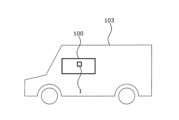
- 請求項1から9のいずれか1つに記載のロータ(1)を有する電気機器(100)、特に電動機、を備える車両(103)。
Applications Claiming Priority (2)
| Application Number | Priority Date | Filing Date | Title |
|---|---|---|---|
| DE102018130475.7 | 2018-11-30 | ||
| DE102018130475.7A DE102018130475A1 (de) | 2018-11-30 | 2018-11-30 | Rotor mit einer Wicklung für eine elektrische Maschine |
Publications (2)
| Publication Number | Publication Date |
|---|---|
| JP2020089267A JP2020089267A (ja) | 2020-06-04 |
| JP7655697B2 true JP7655697B2 (ja) | 2025-04-02 |
Family
ID=70681505
Family Applications (1)
| Application Number | Title | Priority Date | Filing Date |
|---|---|---|---|
| JP2019212801A Active JP7655697B2 (ja) | 2018-11-30 | 2019-11-26 | 電気機器用の巻線を有するロータ |
Country Status (4)
| Country | Link |
|---|---|
| US (1) | US11355986B2 (ja) |
| JP (1) | JP7655697B2 (ja) |
| CN (1) | CN111262368B (ja) |
| DE (1) | DE102018130475A1 (ja) |
Families Citing this family (9)
| Publication number | Priority date | Publication date | Assignee | Title |
|---|---|---|---|---|
| DE102020110664A1 (de) * | 2020-04-20 | 2021-10-21 | Audi Aktiengesellschaft | Elektrische Maschine und Kraftfahrzeug |
| DE102020208957A1 (de) * | 2020-07-17 | 2022-01-20 | Vitesco Technologies GmbH | Rotor für eine rotierende elektrische Maschine, elektrische Maschine |
| EP4203263B1 (en) * | 2021-12-23 | 2026-07-22 | Valeo Electrification | Wedge element for an electric excited rotor |
| EP4203267A1 (en) * | 2021-12-23 | 2023-06-28 | Valeo eAutomotive Germany GmbH | Overmolded separately excited rotor |
| DE102022102023A1 (de) | 2022-01-28 | 2023-08-03 | Bayerische Motoren Werke Aktiengesellschaft | Deckschieber und Verfahren zur Abdeckung einer Rotornut |
| WO2026012702A1 (de) * | 2024-07-11 | 2026-01-15 | Robert Bosch Gmbh | Rotor einer elektrischen maschine |
| DE102024129544A1 (de) * | 2024-10-11 | 2026-04-16 | Mahle International Gmbh | Nutverschlusskeil für einen Rotor in einem Elektromotor mit verbesserter elektrischer Isolierung und Formstabilität |
| DE102024135292A1 (de) * | 2024-11-28 | 2026-05-28 | Mahle International Gmbh | Rotor umfassend eine speichenradförmige Wuchtscheibe zur Bereistellung von Kühlkanälen |
| DE102024135372A1 (de) | 2024-11-29 | 2026-06-03 | Valeo Eautomotive Germany Gmbh | Verfahren zum Herstellen einer Rotorvorrichtung, entsprechende Rotorvorrichtung für eine elektrische Maschine und Fahrzeug |
Citations (3)
| Publication number | Priority date | Publication date | Assignee | Title |
|---|---|---|---|---|
| JP2001346350A (ja) | 2000-05-31 | 2001-12-14 | Toshiba Corp | 回転電機の固定子コイル支持装置 |
| JP2003164088A (ja) | 2001-11-28 | 2003-06-06 | Nissan Motor Co Ltd | 電動機の固定子構造 |
| US20040263019A1 (en) | 2003-06-24 | 2004-12-30 | Buchan Neil Fergus | Rotor assembly for dynamo electric machines |
Family Cites Families (16)
| Publication number | Priority date | Publication date | Assignee | Title |
|---|---|---|---|---|
| JPS476303U (ja) * | 1971-02-15 | 1972-09-21 | ||
| FR2708803B1 (fr) * | 1993-07-30 | 1995-10-20 | Jeumont Ind | Machine tournante chemisée. |
| DE4327775A1 (de) * | 1993-08-18 | 1995-02-23 | Abb Management Ag | Nutverschlußanordnung |
| US5892306A (en) * | 1997-03-24 | 1999-04-06 | Emerson Electric Co. | Method and apparatus for balancing a load with a salient pole rotor machine |
| JP3505345B2 (ja) * | 1997-04-10 | 2004-03-08 | 株式会社三協精機製作所 | モータ |
| US6891304B1 (en) * | 2000-09-06 | 2005-05-10 | Quebec Metal Powders Limited | Brush DC motors and AC commutator motor structures with concentrated windings |
| JP5302527B2 (ja) * | 2007-10-29 | 2013-10-02 | 株式会社豊田中央研究所 | 回転電機及びその駆動制御装置 |
| JP5233497B2 (ja) * | 2008-08-18 | 2013-07-10 | 株式会社デンソー | 電動機 |
| US20110025160A1 (en) * | 2009-08-03 | 2011-02-03 | Gm Global Technology Operations, Inc. | Rectangular cross-section windings for electrical machine rotors |
| WO2013110656A1 (de) * | 2012-01-26 | 2013-08-01 | Continental Automotive Gmbh | Rotor für eine rotierende elektrische maschine |
| DE202012000842U1 (de) * | 2012-01-26 | 2012-02-03 | Continental Automotive Gmbh | Rotor für eine rotierende elektrische Maschine und Elektromotor |
| JP5682600B2 (ja) * | 2012-08-07 | 2015-03-11 | トヨタ自動車株式会社 | 回転電機のロータ |
| JP5742804B2 (ja) * | 2012-09-06 | 2015-07-01 | トヨタ自動車株式会社 | 回転電機のロータ及び回転電機 |
| KR101382335B1 (ko) * | 2012-09-17 | 2014-04-09 | 현대자동차 주식회사 | 모터의 회전자와 이를 포함하는 동기 모터 및 권선형 회전자 동기 모터 |
| KR101637676B1 (ko) * | 2014-09-05 | 2016-07-07 | 현대자동차주식회사 | 개선된 웨지를 가지는 회전 전기기기의 전기자 |
| KR101855763B1 (ko) * | 2016-06-03 | 2018-05-09 | 현대자동차 주식회사 | 계자권선형 구동모터 |
-
2018
- 2018-11-30 DE DE102018130475.7A patent/DE102018130475A1/de active Pending
-
2019
- 2019-11-26 JP JP2019212801A patent/JP7655697B2/ja active Active
- 2019-11-29 CN CN201911199974.6A patent/CN111262368B/zh active Active
- 2019-11-29 US US16/699,348 patent/US11355986B2/en active Active
Patent Citations (3)
| Publication number | Priority date | Publication date | Assignee | Title |
|---|---|---|---|---|
| JP2001346350A (ja) | 2000-05-31 | 2001-12-14 | Toshiba Corp | 回転電機の固定子コイル支持装置 |
| JP2003164088A (ja) | 2001-11-28 | 2003-06-06 | Nissan Motor Co Ltd | 電動機の固定子構造 |
| US20040263019A1 (en) | 2003-06-24 | 2004-12-30 | Buchan Neil Fergus | Rotor assembly for dynamo electric machines |
Also Published As
| Publication number | Publication date |
|---|---|
| US20200177046A1 (en) | 2020-06-04 |
| CN111262368B (zh) | 2025-04-08 |
| US11355986B2 (en) | 2022-06-07 |
| DE102018130475A1 (de) | 2020-06-04 |
| CN111262368A (zh) | 2020-06-09 |
| JP2020089267A (ja) | 2020-06-04 |
Similar Documents
| Publication | Publication Date | Title |
|---|---|---|
| CN111262368B (zh) | 具有绕组的电机转子 | |
| EP2621059B1 (en) | Manufacturing method for rotary electrical machine | |
| US20080201935A1 (en) | Manufacturing Method for Rotary Electric Machine and Stator | |
| US11075551B2 (en) | Method for making stator of rotary electrical machine | |
| CN105191074B (zh) | 设置有用于机械地抵抗振动应力的衰减器的电机以及相应衰减器 | |
| JPH06205556A (ja) | 回転子巻線装置及び回転電動機械 | |
| US8604659B2 (en) | Stator with insulation for an electric motor, insulation for a stator, and electric power tool | |
| US10326327B2 (en) | Claw rotor comprising clip for securing end wire of winding, and associated electrical machine | |
| US9960651B2 (en) | Claw rotor provided with an excitation winding insulator, and rotary electrical machine equipped with the claw rotor | |
| CN102598481A (zh) | 设置有激励线圈绝缘件和磁体的爪形转子,和设置有该类型转子的旋转电机 | |
| EP1724904A2 (en) | Rotor for a rotating electric machine with a rotor pole crossover | |
| CN113708521B (zh) | 一种卷绕的电机定子及电机 | |
| JP5278003B2 (ja) | 電動機 | |
| US9438079B2 (en) | Armature end insulator for a power tool motor | |
| US7084545B2 (en) | Electric machine and method of making an electric machine | |
| CN102545442B (zh) | 用于电机的电枢,该电枢的制造方法以及电机 | |
| US10637335B2 (en) | Method for producing wound stator of rotary electrical machine | |
| JP4805509B2 (ja) | 取外し可能な自動締り界磁巻線ブロック | |
| EP4203261A1 (en) | Guided wedge element for an electric excited rotor | |
| JP3815367B2 (ja) | 回転電機の回転子再生方法 | |
| JP7834107B2 (ja) | ブラシレスdcモータのためのステータを製造するための方法及び装置 | |
| CA1055095A (en) | Rotor with form wound coils for synchronous dynamoelectric machine | |
| KR100710365B1 (ko) | 모터 | |
| JP6005554B2 (ja) | 回転電機 | |
| CN113437844A (zh) | 制造线圈的方法、相应的线圈及制造电机的方法 |
Legal Events
| Date | Code | Title | Description |
|---|---|---|---|
| A521 | Request for written amendment filed |
Free format text: JAPANESE INTERMEDIATE CODE: A523 Effective date: 20200131 |
|
| A521 | Request for written amendment filed |
Free format text: JAPANESE INTERMEDIATE CODE: A523 Effective date: 20200205 |
|
| A621 | Written request for application examination |
Free format text: JAPANESE INTERMEDIATE CODE: A621 Effective date: 20221026 |
|
| A977 | Report on retrieval |
Free format text: JAPANESE INTERMEDIATE CODE: A971007 Effective date: 20231018 |
|
| A131 | Notification of reasons for refusal |
Free format text: JAPANESE INTERMEDIATE CODE: A131 Effective date: 20231031 |
|
| RD04 | Notification of resignation of power of attorney |
Free format text: JAPANESE INTERMEDIATE CODE: A7424 Effective date: 20231124 |
|
| A521 | Request for written amendment filed |
Free format text: JAPANESE INTERMEDIATE CODE: A523 Effective date: 20240130 |
|
| A02 | Decision of refusal |
Free format text: JAPANESE INTERMEDIATE CODE: A02 Effective date: 20240308 |
|
| A521 | Request for written amendment filed |
Free format text: JAPANESE INTERMEDIATE CODE: A523 Effective date: 20240704 |
|
| A911 | Transfer to examiner for re-examination before appeal (zenchi) |
Free format text: JAPANESE INTERMEDIATE CODE: A911 Effective date: 20240712 |
|
| A912 | Re-examination (zenchi) completed and case transferred to appeal board |
Free format text: JAPANESE INTERMEDIATE CODE: A912 Effective date: 20240726 |
|
| A61 | First payment of annual fees (during grant procedure) |
Free format text: JAPANESE INTERMEDIATE CODE: A61 Effective date: 20250321 |
|
| R150 | Certificate of patent or registration of utility model |
Ref document number: 7655697 Country of ref document: JP Free format text: JAPANESE INTERMEDIATE CODE: R150 |