JP7655872B2 - ULTRASONIC IMAGING APPARATUS AND SIGNAL PROCESSING METHOD - Google Patents
ULTRASONIC IMAGING APPARATUS AND SIGNAL PROCESSING METHOD Download PDFInfo
- Publication number
- JP7655872B2 JP7655872B2 JP2022007445A JP2022007445A JP7655872B2 JP 7655872 B2 JP7655872 B2 JP 7655872B2 JP 2022007445 A JP2022007445 A JP 2022007445A JP 2022007445 A JP2022007445 A JP 2022007445A JP 7655872 B2 JP7655872 B2 JP 7655872B2
- Authority
- JP
- Japan
- Prior art keywords
- signal
- phase
- circuit
- ultrasonic
- received
- Prior art date
- Legal status (The legal status is an assumption and is not a legal conclusion. Google has not performed a legal analysis and makes no representation as to the accuracy of the status listed.)
- Active
Links
Images


Classifications
-
- G—PHYSICS
- G01—MEASURING; TESTING
- G01S—RADIO DIRECTION-FINDING; RADIO NAVIGATION; DETERMINING DISTANCE OR VELOCITY BY USE OF RADIO WAVES; LOCATING OR PRESENCE-DETECTING BY USE OF THE REFLECTION OR RERADIATION OF RADIO WAVES; ANALOGOUS ARRANGEMENTS USING OTHER WAVES
- G01S7/00—Details of systems according to groups G01S13/00, G01S15/00, G01S17/00
- G01S7/52—Details of systems according to groups G01S13/00, G01S15/00, G01S17/00 of systems according to group G01S15/00
- G01S7/52017—Details of systems according to groups G01S13/00, G01S15/00, G01S17/00 of systems according to group G01S15/00 particularly adapted to short-range imaging
- G01S7/52023—Details of receivers
- G01S7/52025—Details of receivers for pulse systems
-
- A—HUMAN NECESSITIES
- A61—MEDICAL OR VETERINARY SCIENCE; HYGIENE
- A61B—DIAGNOSIS; SURGERY; IDENTIFICATION
- A61B8/00—Diagnosis using ultrasonic, sonic or infrasonic waves
- A61B8/54—Control of the diagnostic device
-
- A—HUMAN NECESSITIES
- A61—MEDICAL OR VETERINARY SCIENCE; HYGIENE
- A61B—DIAGNOSIS; SURGERY; IDENTIFICATION
- A61B8/00—Diagnosis using ultrasonic, sonic or infrasonic waves
- A61B8/44—Constructional features of the ultrasonic, sonic or infrasonic diagnostic device
- A61B8/4483—Constructional features of the ultrasonic, sonic or infrasonic diagnostic device characterised by features of the ultrasound transducer
-
- A—HUMAN NECESSITIES
- A61—MEDICAL OR VETERINARY SCIENCE; HYGIENE
- A61B—DIAGNOSIS; SURGERY; IDENTIFICATION
- A61B8/00—Diagnosis using ultrasonic, sonic or infrasonic waves
- A61B8/44—Constructional features of the ultrasonic, sonic or infrasonic diagnostic device
- A61B8/4477—Constructional features of the ultrasonic, sonic or infrasonic diagnostic device using several separate ultrasound transducers or probes
-
- A—HUMAN NECESSITIES
- A61—MEDICAL OR VETERINARY SCIENCE; HYGIENE
- A61B—DIAGNOSIS; SURGERY; IDENTIFICATION
- A61B8/00—Diagnosis using ultrasonic, sonic or infrasonic waves
- A61B8/44—Constructional features of the ultrasonic, sonic or infrasonic diagnostic device
- A61B8/4483—Constructional features of the ultrasonic, sonic or infrasonic diagnostic device characterised by features of the ultrasound transducer
- A61B8/4494—Constructional features of the ultrasonic, sonic or infrasonic diagnostic device characterised by features of the ultrasound transducer characterised by the arrangement of the transducer elements
-
- A—HUMAN NECESSITIES
- A61—MEDICAL OR VETERINARY SCIENCE; HYGIENE
- A61B—DIAGNOSIS; SURGERY; IDENTIFICATION
- A61B8/00—Diagnosis using ultrasonic, sonic or infrasonic waves
- A61B8/52—Devices using data or image processing specially adapted for diagnosis using ultrasonic, sonic or infrasonic waves
-
- A—HUMAN NECESSITIES
- A61—MEDICAL OR VETERINARY SCIENCE; HYGIENE
- A61B—DIAGNOSIS; SURGERY; IDENTIFICATION
- A61B8/00—Diagnosis using ultrasonic, sonic or infrasonic waves
- A61B8/52—Devices using data or image processing specially adapted for diagnosis using ultrasonic, sonic or infrasonic waves
- A61B8/5207—Devices using data or image processing specially adapted for diagnosis using ultrasonic, sonic or infrasonic waves involving processing of raw data to produce diagnostic data, e.g. for generating an image
-
- A—HUMAN NECESSITIES
- A61—MEDICAL OR VETERINARY SCIENCE; HYGIENE
- A61B—DIAGNOSIS; SURGERY; IDENTIFICATION
- A61B8/00—Diagnosis using ultrasonic, sonic or infrasonic waves
- A61B8/52—Devices using data or image processing specially adapted for diagnosis using ultrasonic, sonic or infrasonic waves
- A61B8/5215—Devices using data or image processing specially adapted for diagnosis using ultrasonic, sonic or infrasonic waves involving processing of medical diagnostic data
- A61B8/5223—Devices using data or image processing specially adapted for diagnosis using ultrasonic, sonic or infrasonic waves involving processing of medical diagnostic data for extracting a diagnostic or physiological parameter from medical diagnostic data
-
- A—HUMAN NECESSITIES
- A61—MEDICAL OR VETERINARY SCIENCE; HYGIENE
- A61B—DIAGNOSIS; SURGERY; IDENTIFICATION
- A61B8/00—Diagnosis using ultrasonic, sonic or infrasonic waves
- A61B8/52—Devices using data or image processing specially adapted for diagnosis using ultrasonic, sonic or infrasonic waves
- A61B8/5269—Devices using data or image processing specially adapted for diagnosis using ultrasonic, sonic or infrasonic waves involving detection or reduction of artifacts
-
- G—PHYSICS
- G01—MEASURING; TESTING
- G01S—RADIO DIRECTION-FINDING; RADIO NAVIGATION; DETERMINING DISTANCE OR VELOCITY BY USE OF RADIO WAVES; LOCATING OR PRESENCE-DETECTING BY USE OF THE REFLECTION OR RERADIATION OF RADIO WAVES; ANALOGOUS ARRANGEMENTS USING OTHER WAVES
- G01S15/00—Systems using the reflection or reradiation of acoustic waves, e.g. sonar systems
- G01S15/88—Sonar systems specially adapted for specific applications
- G01S15/89—Sonar systems specially adapted for specific applications for mapping or imaging
- G01S15/8906—Short-range imaging systems; Acoustic microscope systems using pulse-echo techniques
- G01S15/8909—Short-range imaging systems; Acoustic microscope systems using pulse-echo techniques using a static transducer configuration
- G01S15/8915—Short-range imaging systems; Acoustic microscope systems using pulse-echo techniques using a static transducer configuration using a transducer array
-
- G—PHYSICS
- G01—MEASURING; TESTING
- G01S—RADIO DIRECTION-FINDING; RADIO NAVIGATION; DETERMINING DISTANCE OR VELOCITY BY USE OF RADIO WAVES; LOCATING OR PRESENCE-DETECTING BY USE OF THE REFLECTION OR RERADIATION OF RADIO WAVES; ANALOGOUS ARRANGEMENTS USING OTHER WAVES
- G01S7/00—Details of systems according to groups G01S13/00, G01S15/00, G01S17/00
- G01S7/52—Details of systems according to groups G01S13/00, G01S15/00, G01S17/00 of systems according to group G01S15/00
- G01S7/52017—Details of systems according to groups G01S13/00, G01S15/00, G01S17/00 of systems according to group G01S15/00 particularly adapted to short-range imaging
- G01S7/52023—Details of receivers
- G01S7/52025—Details of receivers for pulse systems
- G01S7/52026—Extracting wanted echo signals
-
- G—PHYSICS
- G01—MEASURING; TESTING
- G01S—RADIO DIRECTION-FINDING; RADIO NAVIGATION; DETERMINING DISTANCE OR VELOCITY BY USE OF RADIO WAVES; LOCATING OR PRESENCE-DETECTING BY USE OF THE REFLECTION OR RERADIATION OF RADIO WAVES; ANALOGOUS ARRANGEMENTS USING OTHER WAVES
- G01S7/00—Details of systems according to groups G01S13/00, G01S15/00, G01S17/00
- G01S7/52—Details of systems according to groups G01S13/00, G01S15/00, G01S17/00 of systems according to group G01S15/00
- G01S7/52017—Details of systems according to groups G01S13/00, G01S15/00, G01S17/00 of systems according to group G01S15/00 particularly adapted to short-range imaging
- G01S7/52046—Techniques for image enhancement involving transmitter or receiver
-
- G—PHYSICS
- G10—MUSICAL INSTRUMENTS; ACOUSTICS
- G10K—SOUND-PRODUCING DEVICES; METHODS OR DEVICES FOR PROTECTING AGAINST, OR FOR DAMPING, NOISE OR OTHER ACOUSTIC WAVES IN GENERAL; ACOUSTICS NOT OTHERWISE PROVIDED FOR
- G10K11/00—Methods or devices for transmitting, conducting or directing sound in general; Methods or devices for protecting against, or for damping, noise or other acoustic waves in general
- G10K11/18—Methods or devices for transmitting, conducting or directing sound
- G10K11/26—Sound-focusing or directing, e.g. scanning
- G10K11/34—Sound-focusing or directing, e.g. scanning using electrical steering of transducer arrays, e.g. beam steering
- G10K11/341—Circuits therefor
- G10K11/346—Circuits therefor using phase variation
-
- A—HUMAN NECESSITIES
- A61—MEDICAL OR VETERINARY SCIENCE; HYGIENE
- A61B—DIAGNOSIS; SURGERY; IDENTIFICATION
- A61B8/00—Diagnosis using ultrasonic, sonic or infrasonic waves
- A61B8/44—Constructional features of the ultrasonic, sonic or infrasonic diagnostic device
- A61B8/4483—Constructional features of the ultrasonic, sonic or infrasonic diagnostic device characterised by features of the ultrasound transducer
- A61B8/4488—Constructional features of the ultrasonic, sonic or infrasonic diagnostic device characterised by features of the ultrasound transducer the transducer being a phased array
-
- G—PHYSICS
- G01—MEASURING; TESTING
- G01S—RADIO DIRECTION-FINDING; RADIO NAVIGATION; DETERMINING DISTANCE OR VELOCITY BY USE OF RADIO WAVES; LOCATING OR PRESENCE-DETECTING BY USE OF THE REFLECTION OR RERADIATION OF RADIO WAVES; ANALOGOUS ARRANGEMENTS USING OTHER WAVES
- G01S15/00—Systems using the reflection or reradiation of acoustic waves, e.g. sonar systems
- G01S15/88—Sonar systems specially adapted for specific applications
- G01S15/89—Sonar systems specially adapted for specific applications for mapping or imaging
- G01S15/8906—Short-range imaging systems; Acoustic microscope systems using pulse-echo techniques
- G01S15/8997—Short-range imaging systems; Acoustic microscope systems using pulse-echo techniques using synthetic aperture techniques
Landscapes
- Health & Medical Sciences (AREA)
- Life Sciences & Earth Sciences (AREA)
- Engineering & Computer Science (AREA)
- Physics & Mathematics (AREA)
- General Health & Medical Sciences (AREA)
- Animal Behavior & Ethology (AREA)
- Veterinary Medicine (AREA)
- Public Health (AREA)
- Surgery (AREA)
- Molecular Biology (AREA)
- Medical Informatics (AREA)
- Biophysics (AREA)
- Nuclear Medicine, Radiotherapy & Molecular Imaging (AREA)
- Pathology (AREA)
- Radiology & Medical Imaging (AREA)
- Biomedical Technology (AREA)
- Heart & Thoracic Surgery (AREA)
- Radar, Positioning & Navigation (AREA)
- Remote Sensing (AREA)
- Computer Vision & Pattern Recognition (AREA)
- Computer Networks & Wireless Communication (AREA)
- General Physics & Mathematics (AREA)
- Gynecology & Obstetrics (AREA)
- Acoustics & Sound (AREA)
- Multimedia (AREA)
- Physiology (AREA)
- Ultra Sonic Daignosis Equipment (AREA)
- Investigating Or Analyzing Materials By The Use Of Ultrasonic Waves (AREA)
Description
本発明は、超音波を用いて被検体内の画像を撮像する超音波撮像技術に関する。 The present invention relates to ultrasound imaging technology that uses ultrasound to capture images inside a subject.
超音波撮像技術とは、超音波(聞くことを意図しない音波、一般的には20kHz以上の高周波数の音波)を用いて人体をはじめとする被検体の内部を非侵襲的に画像化する技術である。 Ultrasound imaging technology is a technique that uses ultrasound (sound waves that are not intended to be heard, generally high-frequency sound waves of 20 kHz or higher) to non-invasively image the inside of a subject, including the human body.
超音波撮像装置による超音波の送受信は、有限の開口径を持つ超音波素子アレイによって行われるため、開口部のエッジによる超音波の回折の影響を受け、方位角方向の分解能を向上させることが難しい。そのため、適応ビームフォーマや、開口合成などの新しい整相方式が提案されている。 Ultrasound imaging devices transmit and receive ultrasound using an array of ultrasound elements with a finite aperture diameter, which makes it difficult to improve the resolution in the azimuth direction due to the effect of ultrasound diffraction by the edges of the aperture. For this reason, new beamforming methods such as adaptive beamformers and aperture synthesis have been proposed.
特許文献1には、集束型送信を行う超音波撮像技術において、仮想音源法を改良した方法を用いて、開口合成を行う技術が開示されている。具体的には、超音波ビームのエネルギが焦点に収束する領域(特許文献1の図2の領域A)では、焦点を仮想音源とみなして開口合成を行い、その周辺の超音波エネルギが拡散する領域(領域B,C)では探触子の端部から球面波が放射されたとみなして開口合成を行う。 Patent Document 1 discloses a technology for performing aperture synthesis using an improved virtual sound source method in ultrasound imaging technology with focused transmission. Specifically, in the region where the energy of the ultrasound beam converges at the focus (region A in Figure 2 of Patent Document 1), aperture synthesis is performed by regarding the focus as a virtual sound source, and in the surrounding regions where the ultrasound energy is diffused (regions B and C), aperture synthesis is performed by regarding a spherical wave as being emitted from the end of the probe.
一方、特許文献2には、2種類以上の遅延時間によって受信信号をそれぞれ遅延加算する2以上の遅延加算部を備えた超音波撮像装置が開示されている。第1の遅延加算部は、超音波素子から送信された送信ビーム(干渉波)から生じた受信信号を整相する第1の遅延時間によって遅延加算する。第2の遅延加算部は、送信ビームとは位相の異なる回折波(球面波)から生じた受信信号を整相する第2の遅延時間によって受信信号を遅延加算する。第1および第2遅延加算部がそれぞれ遅延加算した後の信号は合成される。 On the other hand, Patent Document 2 discloses an ultrasound imaging device equipped with two or more delay and addition units that delay and add received signals by two or more types of delay times. The first delay and addition unit delays and adds received signals generated from a transmission beam (interference wave) transmitted from an ultrasonic element by a first delay time that phases the received signals. The second delay and addition unit delays and adds received signals by a second delay time that phases the received signals generated from a diffracted wave (spherical wave) that has a different phase from the transmitted beam. The signals after the first and second delay and addition units have performed delay and addition are combined.
特許文献1の技術は、送信間で開口合成を行う技術であり、1回の送信のみでは、高精度な画像を得ることはできない。 The technology in Patent Document 1 performs aperture synthesis between transmissions, and a high-precision image cannot be obtained with only one transmission.
特許文献2の技術は、2種類以上の遅延時間によって受信信号をそれぞれ遅延させた後加算するため、一つの超音波素子に対して、2以上の遅延回路を設置する必要があり、回路規模が増大する。 The technology in Patent Document 2 delays received signals by two or more different delay times and then adds them together, so two or more delay circuits must be installed for one ultrasonic element, which increases the circuit size.
発明の目的は、回路規模を抑制しながら、被検体の深さ方向に複雑に伝搬していく超音波によって生じた受信信号を、効率よく整相加算して、より高解像度な画像を生成することにある。 The objective of the invention is to efficiently phase and add received signals generated by ultrasonic waves that propagate in a complex manner in the depth direction of the subject while minimizing the circuit scale, thereby generating images with higher resolution.
本発明の超音波撮像装置は、接続されている超音波素子アレイの複数の超音波素子からそれぞれ、所定の送信焦点に集束するように位相を遅延させた超音波を被検体に対して送信させる送信ビームフォーマと、超音波の送信を受けた被検体から超音波素子アレイに戻った超音波を、超音波素子アレイの複数の超音波素子が受信して出力する受信信号を、被検体内に設定した受信焦点ごとに受信ビームフォーミングして整相信号を生成する受信ビームフォーマとを有する。受信ビームフォーマは、受信信号を遅延させる遅延回路と、加算回路と、位相補償回路とを含む。遅延回路は、複数の超音波素子が出力した受信信号をそれぞれ受信焦点の深度に応じた所定の遅延量で遅延させる。加算回路は、遅延回路が遅延後の受信信号を加算して整相信号を生成する。位相補償回路は、遅延回路が遅延させた受信信号、または、整相信号を分岐させ、分岐させた受信信号または整相信号の位相を所定の位相シフト量だけシフトさせた位相補償後信号を生成し、分岐前の受信信号または整相信号と加算する。 The ultrasonic imaging device of the present invention has a transmission beamformer that transmits ultrasonic waves from a plurality of ultrasonic elements of a connected ultrasonic element array to a subject, the phase of which is delayed so as to be focused on a predetermined transmission focal point, and a reception beamformer that generates a phased signal by performing reception beamforming for each reception focal point set in the subject on the reception signals that are received and output by the plurality of ultrasonic elements of the ultrasonic element array and that are received from the subject that received the transmitted ultrasonic waves and returned to the ultrasonic element array. The reception beamformer includes a delay circuit that delays the reception signal, an addition circuit, and a phase compensation circuit. The delay circuit delays the reception signals output by the plurality of ultrasonic elements by a predetermined delay amount according to the depth of the reception focal point. The addition circuit adds the reception signals delayed by the delay circuit to generate a phased signal. The phase compensation circuit branches the reception signal or the phased signal delayed by the delay circuit, shifts the phase of the branched reception signal or the phased signal by a predetermined phase shift amount to generate a phase-compensated signal, and adds it to the reception signal or the phased signal before branching.
本発明によれば、送信ビームだけでなく、複数の超音波素子からそれぞれ送信され、被検体の深さ方向に複雑に伝搬していく球面波によって生じた受信信号を、効率よく整相加算して、より高解像度な画像を生成する装置を、回路規模を抑制しながら提供することができる。 The present invention provides a device that efficiently performs phasing and summing not only the transmitted beam but also the received signals generated by spherical waves that are transmitted from multiple ultrasonic elements and propagate in a complex manner in the depth direction of the subject, thereby generating images with higher resolution while keeping the circuit size small.
本発明の一実施形態の超音波撮像装置について説明する。 This article describes an ultrasound imaging device according to one embodiment of the present invention.
<<<第1実施形態>>>
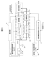
まず、第1実施形態の超音波撮像装置100について図1~図6を用いて説明する。図1は、超音波診断装置の構成を示す図であり、図2は、受信ビームフォーマの構成を示す図である。
<<<First embodiment>>>
First, an
図1に示すように、本実施形態の超音波撮像装置100は、超音波撮像装置本体102、および、超音波撮像装置本体102に接続された超音波素子アレイ101を備えた超音波探触子116を含む。超音波素子アレイ101は、複数の超音波素子をアレイ状に配列した構成である。超音波素子アレイ101において、送信に用いる複数の超音波素子(チャンネル)を送信チャンネルとも呼び、受信に用いる複数の超音波チャンネルを受信チャンネルとも呼ぶ。
As shown in FIG. 1, the
超音波撮像装置本体102の要部について、図1および図2を用いて説明する。超音波撮像装置本体102は、送信ビームフォーマ14、受信ビームフォーマ13、位相補償回路コントロールユニット17、位相シフト量格納部18、送受分離回路10、AD変換器201、画像化処理部15、制御部11、画像表示部16およびコンソール12を備えている。
The main parts of the ultrasound imaging device
受信ビームフォーマ13は、本実施形態では、遅延回路21と、位相補償回路22と、加算回路23とを含む。
In this embodiment, the
複数の超音波素子(受信チャンネル106)からそれぞれ出力された受信信号s1は、AD変換器201でデジタル信号に変換される。受信ビームフォーマ13の遅延回路21は、デジタル信号に変換後の受信信号s1を、受信焦点20の深度に応じて受信チャンネル106ごとに予め定めた遅延時間によってそれぞれ遅延させる。具体的には受信信号s1はメモリ21aからの読み出しタイミングによって制御された粗い(低い)時間分解能の遅延処理と、補間回路21bによる補間処理によって実現される高い時間分解能の遅延処理とを施すことで、遅延させた複数の受信信号s2を生成する。たとえばメモリ21aからの読み出しタイミングで音波の波長程度以上の時間分解能で遅延処理を行い、補間回路21bによる補間処理により、音波の波長の数倍未満の高い分解能での遅延処理を行う。
The received signal s1 output from each of the multiple ultrasonic elements (receiving channels 106) is converted to a digital signal by the
位相補償回路22は、遅延回路21中のメモリ21aから読みだされた直後の複数の受信信号s100のうち1以上の受信信号s100を分岐させ、分岐させた1以上の受信信号s100の位相を所定量シフトさせることにより、位相補償後の受信信号s3を生成する。位相シフト量は、位相補償回路コントロールユニット17からの読み出し指示に応じて、位相シフト量格納部18に予め格納されている受信焦点20の深度ごとの位相シフト量を読み出して、位相補償回路22に設定する。図2の例では、位相補償回路22は、遅延回路21中のメモリ21aから読みだされた粗い時間分解能で遅延が施された全ての受信信号s100を分岐させ、それぞれ位相シフトさせて位相補償後の受信信号s3を生成している。
The
加算回路23は、遅延回路21がそれぞれ遅延させた複数の受信信号s2と、位相補償回路22が生成した1以上の位相補償後の受信信号s3とを加算して、整相信号s4を生成する。
The
このように、本実施形態では、遅延回路21中のメモリ21aから読みだされた直後の受信信号s100の位相をシフトさせることにより、異なる複数種類の遅延時間で遅延させたのとほぼ同様の受信信号s2、s3を、一つの遅延回路21と、位相補償回路22で生成することができる。位相補償回路22は、メモリ21aからの読み出し処理が省けるため、その分のメモリが省けるのみならず、信号処理のための物理的な処理ラインを回路中に用意する必要がなくなるため、遅延回路21のフル構成を複数遅延処理の数の分だけ複数用意するよりも簡素な回路構成で実現できる。よって、被検体90の深さ方向に複雑に伝搬していく超音波によって生じた受信信号を、複数種類の遅延時間を用いて整相加算した場合とほぼ同様の効果を、回路規模を抑制しながら達成し、高解像度な画像を生成することができる。
In this embodiment, by shifting the phase of the received signal s100 immediately after it is read out from the
以下、本実施形態の超音波撮像装置100について詳しく説明する。
The
送信ビームフォーマ14は、接続されている超音波素子アレイ101の複数の超音波素子(送信チャンネル105)にそれぞれ送信信号を出力する。送信チャンネル105は、送信信号を超音波に変換して被検体90に送信する。
The
このとき、送信ビームフォーマ14は、各送信チャンネル105から送信される超音波(球面波)301~306等が相互に干渉して、図3のように所定の深さの送信焦点30において集束するように、送信信号の位相を所定量ずつ遅延させる。これにより、所望の深さの送信焦点30で集束する送信ビーム(干渉波)310を被検体90に照射することができる。なお、図3に示すように、各送信チャンネル105から送信された超音波(球面波)301~306等は、上述の送信ビーム(干渉波)310を形成する他に、一部は球面波301~306等のまま各方向に伝搬し、さらにそれらの一部のみが干渉しあった干渉波を形成したりしながら深さ方向に複雑に伝搬していく。
At this time, the
送信ビーム(干渉波)310や超音波(球面波)301~306や、他の干渉波が伝搬する被検体90内では、これらの波が反射や散乱等され、反射波や散乱波等の一部は、再び超音波素子アレイ101に到達する。到達した波は、超音波素子アレイ101の複数の受信チャンネル106によってそれぞれ受信され、受信信号に変換される。
In the
AD変換器201はそれぞれ、受信チャンネル106の出力する受信信号s1をデジタル信号に変換する。
Each
図2(a)に示すように、受信ビームフォーマ13の遅延回路21は、送受分離回路10およびAD変換器201を介して、複数の受信チャンネル106から受信信号s1を受け取って、被検体90内に設定した受信焦点20の深度に応じて、制御部11が指示した遅延時間によりそれぞれ遅延させる。
As shown in FIG. 2(a), the
ここでは、遅延回路21は、受信チャンネル106ごとにそれぞれ配置された、メモリ21aと、補間回路21bとを含んでいる。
Here, the
メモリ21aはそれぞれ、デジタル信号に変換された受信信号s1を一旦格納する。
Each
補間回路21bは、メモリ21aから受信信号s100を読み出し、補間処理する。このとき、受信信号s100はメモリ21aからの読み出しのタイミングをデジタル信号のクロック単位で調整され、およそ波長以上の遅延精度で受信信号s1を遅延させる。次に補間回路21bでは読み出された受信信号s100を補間処理してクロック単位以下もしくは波長の数倍以下の遅延時間の微調整を行って、制御部11から指示された遅延時間での受信信号s1の遅延を実現させ、遅延後の受信信号s2を生成する。
The
遅延時間は、受信焦点20と受信チャンネル106との距離に応じて予め定められ、遅延時間格納部19に格納されている。制御部11は、遅延時間格納部19から受信焦点20の位置に応じて遅延時間の読み出し指示を与え、遅延回路21に設定する。
The delay time is predetermined according to the distance between the receiving focus 20 and the receiving channel 106, and is stored in the delay
受信信号s2は、各受信チャンネル106の出力する受信信号s1を、受信焦点20と受信チャンネル106との距離に応じた遅延量で遅延させたものであるため、図2に示すように位相が揃っている。 The received signal s2 is the received signal s1 output from each receiving channel 106 delayed by an amount of delay corresponding to the distance between the receiving focal point 20 and the receiving channel 106, so that the phase is aligned as shown in Figure 2.
位相補償回路22は、図2のように補間回路21b毎に配置され、遅延回路21中のメモリ21aから読みだされた直後の受信信号s100を分岐して、その位相を、位相補償回路コントロールユニット17の指示する位相シフト量だけシフトさせ、位相補償後の受信信号s3を生成する。
The
位相シフト量は遅延時間格納部19に格納されている遅延時間と同様に、予め位相シフト量格納部18に格納されており、位相補償回路コントロールユニットからの指示に応じて位相補償回路22に対して与えられる。
The phase shift amount is stored in advance in the phase shift
遅延回路21の中の補間回路21bと、位相補償回路22の構成を図4を用いて具体的に説明する。まず、遅延回路21の中の補間回路21bは、シフトレジスタ41aと補間器42aで構成される。メモリからの読み出し後の受信信号s100はシフトレジスタ41aによる微細な時間シフトと補間器42aによる補間係数の乗算によって、クロック以下もしくは波長の数倍以下の高精度な遅延を実現する。制御部11はメモリ21aからの読み出しタイミングを補間回路21bに対して指示するとともに、遅延時間格納部19に格納されているLUT(ルックアップテーブル)の値を参照し、シフトレジスタ41aの時間シフトと、補間器42aの補間係数である遅延時間とを与える。これにより、遅延が付与された受信信号s2が生成される。
The configuration of the
位相補償回路22は、遅延回路21の補間回路21bと同様の構成であり、シフトレジスタ41bと補間器42bで構成される。メモリ21aからの読み出し後の受信信号s100は分岐され、位相補償回路22のシフトレジスタ41bと補間器42bによりクロック以下もしくは波長の数倍以下の高精度な位相シフトが施される。ここで、位相補償回路22が施す位相シフト量は、受信焦点の深さごとに位相シフト量格納部18(LUT)に予め格納されている。位相シフト量格納部18は、位相補償回路コントロールユニット17からの読み出し命令に従って、位相補償回路22に位相シフト量を送る。また、位相補償回路コントロールユニット17から、タイミングなどの制御信号が、位相補償回路22に送られる。これにより位相補償回路22によって位相補償後の受信信号s3が生成される。
The
加算回路23は、遅延回路21の補間回路21bが出力する、各受信チャンネル106の受信信号の遅延後の受信信号s2と、位相補償回路22が出力する受信信号s2を位相シフトさせた受信信号s3とを加算することにより、整相信号s4を生成することができる。
The
なお、加算回路23は、図4に示すように、それぞれのチャンネル毎に受信信号s2受信信号s3を加算し、その後にその加算後チャンネルごとの信号について全チャンネル間の加算を行う形であっても良いし、図2に示すように、すべてのチャンネルの受信信号s2と受信信号s3を同時に加算する形であっても良い。
The
このように、遅延後の受信信号s2と、受信信号s2を位相シフトさせた受信信号s3とを加算することにより、送信ビーム310により生じた受信信号のみならず、球面波301~306等のまま伝搬する波、または、それらの一部が干渉した干渉波等から生じた受信信号からも整相信号を生成することが可能である。これを以下説明する。 In this way, by adding the delayed received signal s2 and the received signal s3 obtained by phase-shifting the received signal s2, it is possible to generate a phased signal not only from the received signal generated by the transmission beam 310, but also from received signals generated by waves propagating as spherical waves 301-306, etc., or interference waves in which some of these waves interfere with each other. This is explained below.
遅延時間格納部19には、受信ビームフォーマ13が受信信号s1を遅延させる際に用いる遅延時間が、超音波素子(受信チャンネル106)ごとに格納されている。この遅延時間は、受信ビームフォーマ13が制御部11によって設定された受信走査線上の複数の受信焦点20に順次焦点を合わせるため、受信焦点20と受信チャンネル106との距離によって異なり、例えば図5の破線の曲線350に示すように、受信焦点20の深度によって変化する。ここでは、深度ごとの遅延時間の変化を遅延曲線とも呼ぶ。
The delay
本実施形態では、送信ビーム310により生じた受信信号のみならず、球面波301~306等のまま伝搬する波や、それらの一部が干渉した干渉波等から生じた受信信号からも整相信号を生成するために、送信ビーム310により生じた受信信号を受信焦点20に焦点を合わせるための遅延時間350とは異なる遅延時間351で受信信号s1を遅延させた受信信号と同様の信号(受信信号s2)を、受信信号s1の位相シフトにより生成する。 In this embodiment, in order to generate a phased signal not only from the received signal generated by the transmission beam 310, but also from waves propagating as spherical waves 301-306 and the like, and from received signals generated from interference waves resulting from interference between some of these waves, a signal (received signal s2) similar to the received signal obtained by delaying received signal s1 by a delay time 351 different from the delay time 350 for focusing the received signal generated by the transmission beam 310 on the receiving focal point 20 is generated by shifting the phase of received signal s1.
例えば、図5のように、送信ビーム310により生じた受信信号を受信焦点20に焦点を合わせるための遅延時間(送信ビーム用遅延時間)350に対し、球面波301により生じた反射波の受信信号の受信信号を、受信焦点20に焦点を合わせるために必要な遅延時間(球面波用遅延時間)351とすると、球面波用遅延時間351によって受信信号s1を遅延させた後加算して整相信号s7を得るためには、図2(b)のようにもう一組の遅延回路121および加算回路123を用意する必要がある。そして、受信チャンネル106からの受信信号s1を分岐させて、もう一組の遅延回路121により、球面波用遅延時間351で遅延させ、加算回路123により加算して受信信号s6を得る必要がある。 For example, as shown in FIG. 5, if the delay time (transmitting beam delay time) 350 for focusing the received signal generated by the transmitting beam 310 on the receiving focal point 20 is taken as 351, the delay time (spherical wave delay time) required for focusing the received signal of the reflected wave generated by the spherical wave 301 on the receiving focal point 20, in order to delay the received signal s1 by the spherical wave delay time 351 and then add it to obtain the phased signal s7, it is necessary to prepare another set of delay circuits 121 and adder circuits 123 as shown in FIG. 2(b). Then, it is necessary to branch the received signal s1 from the receiving channel 106, delay it by the spherical wave delay time 351 by another set of delay circuits 121, and add it by the adder circuit 123 to obtain the received signal s6.
発明者らは、球面波用遅延時間351で遅延させた受信信号s6は、送信ビーム用遅延時間350で遅延させた受信信号s2と大きな位相差を持たず、その位相差が、一波長(2πrad)以内に納まることを気づいた。特に、各チャンネルから送信される球面波自体は全体としては一波長以上の位相差を有するが、本発明における送信ビーム用遅延時間による遅延信号と、球面波用遅延時間による遅延信号を加算する場合には、一波長以上の位相差で加算を行うとお互いの位相ズレによる分解能劣化が支配的となり、かえって分解能劣化に繋がり、有効な画質向上効果が得られないことを見出した。そこで、発明者らは、遅延時間350で遅延後の受信信号s2の位相との位相差を、メモリからの読み出しによって粗い遅延時間が付与された直後の信号s100を用い、位相補償回路22で予め定めた微小な位相シフト量だけシフトさせることにより、遅延時間351異なる遅延時間351で遅延させた受信信号s6と同様の波形および位相の受信信号s3を生成する構成とした。
The inventors noticed that the received signal s6 delayed by the spherical wave delay time 351 does not have a large phase difference with the received signal s2 delayed by the transmission beam delay time 350, and that the phase difference is within one wavelength (2πrad). In particular, the spherical waves themselves transmitted from each channel have a phase difference of one wavelength or more overall, but when adding the delayed signal due to the transmission beam delay time in the present invention and the delayed signal due to the spherical wave delay time, they found that if the addition is performed with a phase difference of one wavelength or more, the degradation of resolution due to the mutual phase shift becomes dominant, which leads to a degradation of resolution and an effective improvement in image quality cannot be obtained. Therefore, the inventors have devised a configuration in which the phase difference between the phase of the received signal s2 delayed by the delay time 350 is shifted by a predetermined minute phase shift amount in the
位相補償回路22は、もう一組の遅延回路121と加算回路123を用意する場合と比較して、メモリの規模および遅延処理の回路規模を低減できるため、本実施形態の超音波撮像装置では、回路規模を低減しながらも、複数の遅延時間350,351で受信信号s1を遅延させた場合と同様の整相信号s4を生成することができる。
The
具体的には、本実施形態の図2(a)の構成では、図4のようにシフトレジスタ41a、41bおよび補間器42a、42bを2以上100以下の有限なタップ数(デジタルフィルタの段数)で構成すれば足りる。これに対し、図2(b)の比較例のようにもう一組の遅延回路121の遅延線を複数用意する場合には、一走査線の全サンプル数分の1000以上のメモリバッファ領域が必要になる。よって、本実施形態の図2(a)構成は、図2(b)の比較例と比べて、はるかに少ない実装規模でありながら、整相信号s4を生成することのできる回路を実現可能である。
Specifically, in the configuration of FIG. 2(a) of this embodiment, it is sufficient to configure the
なお、位相補償回路22の位相シフト量は、遅延時間351の深さ方向の変化に応じて変化させることにより、受信焦点20が各深さにおいて、受信信号s3を得ることができる。
The amount of phase shift in the
このように、本実施形態では、送信ビーム310により生じた受信信号のみならず、球面波301~306等のいずれか、または、それらの一部が干渉した干渉波等から生じた受信信号の位相をそろえ、受信信号s2、s3を生成することできる。これにより、受信ビームフォーマ13は、同一の受信信号から、送信ビーム310により生じた受信信号s2の情報と、球面波301等のいずれかにより生じた受信信号s3の情報が反映された整相信号s4を同一の受信走査線について得ることができる。よって、送信ビーム310のみについて得た整相信号よりも、高解像度の整相信号を得ることができる。
In this manner, in this embodiment, it is possible to align the phases of not only the received signal generated by the transmission beam 310, but also the received signal generated by any of the spherical waves 301 to 306, etc., or an interference wave in which a part of them interferes, to generate the received signals s2 and s3. This allows the receive
制御部11は、送信チャンネル105を移動させながら、画像生成に必要な数の受信走査線の整相信号が得られるまで送受信を繰り返すように各部を制御する。なお、この制御方法はリニア(線形)走査、コンベック走査などのスキャン(走査)方式の場合である。セクタ(フェーズドアレイ)型走査の場合には、送信と受信の口径は同じであるが、受信走査線36を角度方向に傾けることで2次元平面上に複数の送信および受信走査線を設定し、その方向に沿って扇形領域の撮像を行うような形態をとる。例えば中心を探触子口径の中心とした±45°や±60°の扇形形状の中に50-1300本程度の走査線が用意されるような形態がある。この場合でも制御部11は、送信チャンネル105の代わりに送信の角度方向を移動させながら、画像生成に必要な数の受信走査線36の整相信号が得られるまで送受信を繰り返すように各部を制御する。
The
画像化処理部15は、画像生成に必要な数の整相信号から画像を生成し、接続されている画像表示部16に表示させる。例えば、画像化処理部15は、遅延加算後の整相信号に対するデジタルフィルタ処理、補間処理などの信号処理および、検波処理、包絡線抽出処理といったRF(Radio Frequency)信号から輝度信号への変換処理、および、複数の整相信号から生成された輝度信号それぞれサンプリングし、走査方式に応じたスキャンコンバージョン(座標変換)処理を施して、ピクセルごとの信号強度・輝度値に変換する画像処理を行うことにより画像信号を生成し、画像信号を並べることにより画像を生成する。
The
つぎに、本実施形態の超音波撮像装置の撮像時の各部の動作について、図6を用いて説明する。 Next, the operation of each part during imaging of the ultrasound imaging device of this embodiment will be explained using FIG. 6.
(ステップ131)
まず、制御部11は、コンソール12を介して撮像条件パラメータおよび/または撮像パラメータに基づいて設定される送受信パラメータおよび/または接続されている超音波探触子116の種類を受け付ける。送受信パラメータは、例えば、送信開口径、受信開口系、周波数(中心周波数、周波数帯域)、送信フォーカス位置、送信パルス波の形状(波数・振幅)等である。
(Step 131)
First, the
(ステップ132)
制御部11は、ステップ131で受け付けた条件等に基づいて、送信ビーム310の形状を計算により求める。
(Step 132)
The
(ステップ133)
制御部11は、送信焦点30の位置、送信周波数、送信回数等の送信条件を送信ビームフォーマ14に受け渡す。送信ビームフォーマ14は、送信信号を生成し、超音波素子アレイ101の送信チャンネル105の超音波素子に出力する。送信チャンネル105の超音波素子はそれぞれ、送信信号を超音波に変換して送信する。超音波素子アレイ101の受信チャンネル106は、ステップ135の送信により生じた被検体からの音波を受信し、受信信号s1を出力する。
(Step 133)
The
(ステップ134)
遅延回路21は、受信信号s1をメモリ21aに一旦格納し、補間回路21bがメモリ21aから受信信号s100をクロック単位のタイミングで読み出して粗い時間分解能で遅延させ、補間回路21bでは読み出された受信信号s100を補間処理してクロック単位以下もしくは波長の数倍以下の高い時間分解能でさらに遅延させ、受信信号s2を出力する。これにより、制御部11の制御下で、遅延時間格納部19が補間回路21bに指示した遅延時間で、受信信号s1の遅延を実現させ、遅延後の受信信号s2を生成する。
(Step 134)
The
(ステップ135)
位相補償回路22は、遅延回路21中のメモリ21aから出力された直後の受信信号s100を分岐させ、さらに分岐後の受信信号s100の位相をシフトさせ、位相シフト後の受信信号s3を生成する。なお、位相シフト量は、位相シフト量格納部18に予め格納されている位相シフト量であり、位相補償回路コントロールユニット17からの制御下で、位相シフト量格納部18から位相補償回路22に設定された値である。
(Step 135)
The
(ステップ136)
加算回路23は、遅延回路21の遅延後の受信信号s2と、位相補償回路22の位相シフト後の受信信号s3を加算して、整相信号s4を生成する。
(Step 136)
The
(ステップ137)
画像化処理部15は、受信走査線ごとの整相信号s4を信号処理および画像処理して画像を生成する。
(Step 137)
The
このように、本実施形態では、送信ビーム310により生じた受信信号s2のみならず、球面波301~306等のいずれか、または、それらの一部が干渉した干渉波等から生じた受信信号と同等の受信信号s3を位相シフトにより生成することできる。これにより、送信ビーム310により生じた受信信号s2の情報と、球面波301等のいずれかにより生じた受信信号s3の情報が反映された高解像度の画像を、回路規模を抑制した受信ビームフォーマ13により少ない演算量で生成することができる。
In this way, in this embodiment, it is possible to generate not only the received signal s2 generated by the transmission beam 310, but also the received signal s3 equivalent to the received signal generated from any of the spherical waves 301 to 306, etc., or an interference wave in which a part of them interferes, by phase shifting. As a result, a high-resolution image that reflects the information of the received signal s2 generated by the transmission beam 310 and the information of the received signal s3 generated by any of the spherical waves 301, etc. can be generated with a small amount of calculation by the receive
<変形例1-1:複数本の受信走査線>
第1実施形態の超音波撮像装置の変形例について説明する。
<Modification 1-1: Multiple Receiving Scanning Lines>
A modification of the ultrasonic imaging apparatus of the first embodiment will be described.
本実施形態の超音波撮像装置は、1回の送信で1本の受信走査線について整相信号を得る構成に限定されるものではなく、1回の送信で複数本の受信走査線についてそれぞれ整相信号を生成することも可能である。これにより、1枚の画像を生成するのに必要な送信回数を低減して、高速撮像を行うことが可能である。 The ultrasound imaging device of this embodiment is not limited to a configuration that obtains a phased signal for one receive scan line in one transmission, but is also capable of generating phased signals for multiple receive scan lines in one transmission. This reduces the number of transmissions required to generate one image, making it possible to perform high-speed imaging.
<変形例1-2:送信開口合成>
第1実施形態の超音波撮像装置の別の変形例について説明する。
<Modification 1-2: Transmit Aperture Synthesis>
Another modified example of the ultrasonic imaging apparatus of the first embodiment will be described.
本実施形態の超音波撮像装置は、1回の送信で複数本の受信走査線についてそれぞれ整相信号を生成し、必要に応じて、送信開口合成を行う構成にすることも可能である。その場合、画像化処理部15には、図1のように送信開口合成部15aを配置する。
The ultrasound imaging device of this embodiment can be configured to generate phased signals for multiple receive scan lines in one transmission and perform transmit aperture synthesis as necessary. In that case, a transmit
受信ビームフォーマ13は、1回の送信で得られた受信信号s1について複数本の受信走査線についてそれぞれ整相信号s4を生成する。
The receive
送信開口合成部15aは、1回の送信について得られた複数本の受信走査線の整相信号s4を内蔵するメモリに格納する。送信開口合成部15aは、送信で得られた複数本の受信走査線の整相信号s4と、同一の位置の受信走査線において、前回以前の送信で得られた受信走査線の整相信号s4とを加算して合成し、開口合成後の整相信号を得る。なお、加算する際に、重み付けして加算してもよい。
The transmit
画像化処理部15は、開口合成後の整相信号を用いて画像を生成する。
The
このように、開口合成を行うことにより、生成される画像の空間分解能を向上させることができる。 In this way, aperture synthesis can be used to improve the spatial resolution of the generated image.
また本実施形態は、受信ビームフォーマ13という超音波装置の信号処理最上流での処理であるため、送信開口合成のみならず他の超音波撮像方式、例えば非線形(ハーモニック)撮像、ドプラ撮像、カラーフロー撮像、コヒーレンス撮像、適応ビームフォーミングを利用した撮像など他の超音波撮像方式と組み合わせて用いることができる。
In addition, since this embodiment is performed at the most upstream signal processing stage of the ultrasound device, the receive
<変形例1-3:深度によって重み付け加算>
第1実施形態の超音波撮像装置のさらに別の変形例について説明する。
<Modification 1-3: Depth-Based Weighting Addition>
Another modified example of the ultrasonic imaging apparatus of the first embodiment will be described.
受信ビームフォーマ13の加算回路23は、遅延後の受信信号s2と、位相シフトの受信信号s3とを加算する際に、重みづけした後加算する構成としてもよい。その場合、制御部11は、深度範囲によって、加算回路23の重み付けの重みを変化させることにより、高解像度な画像が得られる適切な重みを設定する構成とすることができる。また、制御部11は、コンソール12を介して、操作者が設定した重みを受け付けることも可能であるし、撮像条件によって重みを変化させることも可能である。
The
<<<第2実施形態>>>
第2実施形態の超音波撮像装置について図7を用いて説明する。図7は、実施形態2の超音波撮像装置の受信ビームフォーマ13の構成を示している。
<<<Second embodiment>>>
An ultrasonic imaging apparatus according to the second embodiment will be described with reference to Fig. 7. Fig. 7 shows the configuration of a receive
図7に示したように、実施形態2の受信ビームフォーマ13は、複数の球面波301~306等や、それらの一部の干渉波等から受信信号の反映された整相信号を得るために、複数の位相補償回路22-1,22-2,22-3を遅延回路21中のメモリ21aから分岐して接続している。
As shown in FIG. 7, the receive
複数の位相補償回路22-1,22-2,22-3は、メモリ21aの出力する受信信号s100を複数に分岐して、それぞれ異なる位相シフト量で位相をシフトさせ、位相シフト後の受信信号s3-1、s3-2、s3-3を生成する。加算回路23は、補間回路21bの出力する受信信号s2と、位相シフト後の受信信号s3-1、s3-2、s3-3を加算して、整相信号s4を生成する。
The multiple phase compensation circuits 22-1, 22-2, and 22-3 split the received signal s100 output from the
位相補償回路22-1,22-2,22-3の位相シフト量は、例えば、図8に示すように複数の球面波301~306等や、それらの一部の干渉波のうちの3種類の波によって、それぞれ受信チャンネル106に生じた受信信号を受信焦点20に焦点を合わせるための遅延時間351、352、353で遅延させた場合と、同等の遅延を生じさせる位相シフト量に、位相補償回路コントロールユニット17により設定されている。
The phase shift amounts of the phase compensation circuits 22-1, 22-2, and 22-3 are set by the phase compensation
これにより、送信ビーム310のみならず、複数の球面波301~306等や、それらの一部の干渉波等によって生じた受信信号の反映された整相信号s4を得ることができる。 This makes it possible to obtain a phased signal s4 that reflects not only the transmitted beam 310, but also the received signal generated by multiple spherical waves 301-306, etc., and some of their interference waves, etc.
また、本実施形態では、一つの位相補償回路22の回路規模が小さいため、複数の位相補償回路22-1,22-2,22-3を配置した場合であっても、全体の回路規模は、複数の遅延回路121を配置する場合より抑制できる。
In addition, in this embodiment, since the circuit size of one
他の構成、動作および効果は、第1実施形態と同様の構成であるので説明を省略する。 The other configurations, operations, and effects are the same as those of the first embodiment, so explanations are omitted.
<変形例2-1:重み付け加算>
第2実施形態の超音波撮像装置の変形例について説明する。
<Modification 2-1: Weighted Addition>
A modification of the ultrasonic imaging apparatus of the second embodiment will be described.
受信ビームフォーマ13の加算回路23は、遅延回路21の受信信号s2、および、複数の位相補償回路22-1,22-2,22-3の位相シフト後の受信信号s3-1、s3-2、s3-3を加算する際に、重みづけした後加算する構成とすることができる。
The
制御部11は、深度範囲によって、加算回路23の重み付けの重みを変化させることにより、高解像度な画像が得られる適切な重みを設定する構成とすることができる。
The
制御部11は、コンソール12を介して、操作者が設定した重みを受け付けることも可能であるし、撮像条件によって重みを変化させることも可能である。
The
<変形例2-2:時系列に位相シフト処理>
第2実施形態の超音波撮像装置の別の変形例について説明する。
<Modification 2-2: Phase shift processing in time series>
Another modified example of the ultrasonic imaging apparatus of the second embodiment will be described.
受信ビームフォーマ13は、位相補償回路22-1,22-2,22-3の代わりに、一つの位相補償回路22とメモリにより、位相シフト後の受信信号s3-1、s3-2、s3-3を生成することも可能である。具体的には、位相補償回路22により、遅延回路21の受信信号s100を位相シフトして位相シフト後の受信信号s3-1を生成して、メモリに格納し、再び、受信信号s2を位相シフトして位相シフト後の受信信号s3-2を生成してメモリに格納する動作を繰り返し、位相シフト後の受信信号s3-1、s3-2、s3-3を生成し、メモリに格納する。また、位相シフトを行わない受信信号s2をメモリに格納する。加算回路23は、メモリから受信信号s2と、位相シフト後の受信信号s3-1、s3-2、s3-3を読み出して、加算する。
Instead of the phase compensation circuits 22-1, 22-2, and 22-3, the receive
この構成では、位相補償回路22が最低一つでよいため、回路規模が小さくて済む。このため、超音波探触子の116の内部に受信ビームフォーマ13を搭載することも可能になる。
In this configuration, at least one
なお、第2実施形態の超音波撮像装置についても、第1実施形態の変形例1-1、1-2、1-3、超音波撮像装置と同様に、1回の送信について複数本の受信走査線を生成して高速撮像を行うことや、送信開口合成を行うことや、深度によって重み付け加算することも可能である。 As with the ultrasonic imaging device of the first embodiment, modified examples 1-1, 1-2, and 1-3, it is also possible for the ultrasonic imaging device of the second embodiment to generate multiple receive scan lines for one transmission to perform high-speed imaging, to perform transmit aperture synthesis, and to perform weighted addition according to depth.
<<<第3実施形態>>>
第3実施形態の超音波撮像装置について図9を用いて説明する。
<<<Third embodiment>>>
An ultrasonic imaging apparatus according to the third embodiment will be described with reference to FIG.
図9のように、実施形態3の超音波撮像装置は、加算回路23の後段に位相補償回路222と、加算回路223を配置した構成である。なお、加算回路23の後には一般的に整相後信号を格納するメモリを用意する。ただし、メモリを用意せず出力信号を時系列に連続して処理しても良い。
As shown in FIG. 9, the ultrasound imaging device of the third embodiment has a configuration in which a phase compensation circuit 222 and an adder circuit 223 are arranged downstream of the
位相補償回路222は、受信ビームフォーマの加算回路23が出力する整相信号s5を分岐して、位相をシフトさせ、位相シフト後の整相信号s10を生成する。また、加算回路223は、加算回路23が出力する整相信号s5と、位相補償回路222が出力する位相シフト後の整相信号s10とを加算し、整相信号s11を生成する。
The phase compensation circuit 222 branches the phased signal s5 output by the
位相補償回路コントロールユニット17は、位相シフト量を、位相補償回路222に設定する。
The phase compensation
画像化処理部15は、加算後の整相信号s11を用いて画像を生成する。
The
他の構成、動作および効果は、第1実施形態と同様の構成であるので説明を省略する。 The other configurations, operations, and effects are the same as those of the first embodiment, so explanations are omitted.
第3実施形態の様に、一度整相加算された信号に対して位相信号を付与することによって、第1実施形態と比べて実装規模を大幅に低減させることができる。第1実施形態においてはチャンネル数分の位相補償回路22を用意する必要があるが、第2実施形態たかだか1つの位相補償回路222を用意するだけでよい。例えばチャンネル数が128であった場合には、実装規模は第1実施形態と比べて約1%以下になる。また、第1実施形態では複数のチャンネルにおける補間処理による丸め誤差が発生し、最終的な画質向上効果を低下させる可能性があるが、第3実施形態ではたかだか1つの位相補償回路222による位相シフトのため、丸め誤差の影響を最小限に抑えることができる。その一方で第1実施形態と比べてチャンネルごとに位相シフトの量を変化させることができないため、設計や調整の自由度が小さくなる。
As in the third embodiment, by adding a phase signal to a signal that has been phase-aligned and added once, the implementation scale can be significantly reduced compared to the first embodiment. In the first embodiment, it is necessary to prepare a
なお、第3実施形態において、位相補償回路222を、第2の実施形態の図7のように、複数個並列に配置し、位相シフト量が異なる複数種類の整相信号を生成し、それらを加算回路223が加算する構成にすることももちろん可能である。 In the third embodiment, it is of course possible to arrange multiple phase compensation circuits 222 in parallel as in FIG. 7 of the second embodiment, generate multiple types of phasing signals with different amounts of phase shift, and add them together using the adder circuit 223.
また、第3実施形態の超音波撮像装置についても、第1実施形態の変形例1-1、1-2、1-3、超音波撮像装置と同様に、1回の送信について複数本の受信走査線を生成して高速撮像を行うことや、送信開口合成を行うことや、加算回路223が深度によって重み付け加算することも可能である。 Also, in the ultrasound imaging device of the third embodiment, like the variations 1-1, 1-2, and 1-3 of the first embodiment and the ultrasound imaging device, it is possible to generate multiple receive scan lines for one transmission to perform high-speed imaging, to perform transmit aperture synthesis, and for the adder circuit 223 to perform weighted addition according to depth.
<<<第4実施形態>>>
第4実施形態の超音波撮像装置について図10を用いて説明する。
<<<Fourth embodiment>>>
An ultrasonic imaging apparatus according to the fourth embodiment will be described with reference to FIG.
本実施形態では、図10に示すように、加算回路23の後段に配置されたデジタルフィルタ224により、加算回路23の出力する整相信号s5の波形を調整し、第3実施形態の超音波撮像装置の出力する整相信号s11と同様の波形の整相信号s12を生成する。デジタルフィルタ224は、加算器、乗算器および遅延器を少なくとも一つ含んで構成され、これらの加算器、乗算器および遅延器等で整相信号s5を処理することにより波形を調整する。
In this embodiment, as shown in FIG. 10, a digital filter 224 arranged after the
デジタルフィルタ224には、フィルタ係数変換部225が接続されている。デジタルフィルタ224としてはデジタルFIRフィルタもしくはデジタルIIRフィルタのいずれかが使用される。フィルタ係数変換部225は、位相シフト量格納部18から受信焦点の深度に対応する位相シフト量を受け取って、位相シフト量に応じて、デジタルフィルタ224の乗算係数や遅延係数等のフィルタ係数(デジタルフィルタ各タップで乗算する重みの値)を変更する。
A filter coefficient conversion unit 225 is connected to the digital filter 224. Either a digital FIR filter or a digital IIR filter is used as the digital filter 224. The filter coefficient conversion unit 225 receives a phase shift amount corresponding to the depth of the reception focus from the phase shift
具体的には、図10に示すように、フィルタ係数変換部225は、位相シフト量格納部18から出力された位相情報(位相シフト量)をデジタルフィルタ224のフィルタ係数に変換し、超音波撮像装置で予め用意されたフィルタ係数に変更を付与する。変更されたフィルタ係数はデジタルフィルタ224に送られ、設定される。デジタルフィルタ224は、整相後信号s5の波形を、変更されたフィルタ係数により処理し、整相信号s12を生成する。これにより、第1実施形態と同等の信号処理を、フィルタ処理により行うことができる。
Specifically, as shown in FIG. 10, the filter coefficient conversion unit 225 converts the phase information (phase shift amount) output from the phase shift
このとき、位相補償回路コントロールユニット17は、第1実施形態と同様に、位相シフト量格納部18に対応する位相シフト量の出力を指示するとともに、位相シフト量に対応する同等なフィルタ係数の変換処理を行うようフィルタ係数変換部への指示を行う。
At this time, the phase compensation
すなわち、第4実施形態の超音波撮像装置は、フィルタ制御により第1実施形態または第3実施形態と同様の整相信号S12を生成することができる。 In other words, the ultrasound imaging device of the fourth embodiment can generate a phased signal S12 similar to that of the first or third embodiment by filter control.
第4実施形態の超音波撮像装置の他の構成、動作および効果は、第1実施形態と同様の構成であるので説明を省略する。また、第4実施形態の超音波撮像装置は、デジタルフィルタ224を用いることで、第1実施形態の超音波撮像装置の効果のみならず、第2実施形態の複数の位相補償回路を具備する超音波撮像装置によって得られる効果も、同時に達成できる。なお、第2実施形態の超音波撮像装置であって位相補償回路22-1等の本数が大きい装置と等価的な効果を、第4実施形態のデジタルフィルタ224を用いる超音波撮像装置で達成しようとする場合、デジタルフィルタ224のフィルタ係数のタップ数(段数)の数を増やせばよい。これにより、第2実施形態における複数の位相補償回路22-1等と等価的な効果を有するフィルタ係数(フィルタ係数列)を生成することができる。 Other configurations, operations, and effects of the ultrasonic imaging device of the fourth embodiment are the same as those of the first embodiment, so description will be omitted. In addition, by using the digital filter 224, the ultrasonic imaging device of the fourth embodiment can simultaneously achieve not only the effects of the ultrasonic imaging device of the first embodiment, but also the effects obtained by the ultrasonic imaging device having multiple phase compensation circuits of the second embodiment. Note that, when trying to achieve an effect equivalent to that of the ultrasonic imaging device of the second embodiment having a large number of phase compensation circuits 22-1, etc., with an ultrasonic imaging device using the digital filter 224 of the fourth embodiment, it is sufficient to increase the number of taps (stages) of the filter coefficients of the digital filter 224. This makes it possible to generate filter coefficients (filter coefficient strings) having an effect equivalent to that of the multiple phase compensation circuits 22-1, etc. in the second embodiment.
また、第4実施形態の超音波撮像装置のデジタルフィルタ224のフィルタ処理による位相シフトの処理は、ハードウェアではなくCPUやGPU上で動作するソフトウェア上で実現される。そのためハードウェアの回路規模を最小限に抑えることができる。また、可変深度フィルタなどのように超音波撮像装置に既に具備されているフィルタブロックを、デジタルフィルタ224としても動作させて位相シフト処理を実施できるため、設計における調整自由度を大きくすることができる。 In addition, the phase shift processing by the filter processing of the digital filter 224 of the ultrasound imaging device of the fourth embodiment is realized not by hardware but by software running on a CPU or GPU. Therefore, the circuit scale of the hardware can be minimized. In addition, a filter block already provided in the ultrasound imaging device, such as a variable depth filter, can also be operated as the digital filter 224 to perform the phase shift processing, which increases the degree of freedom in adjustment in the design.
<<<第5実施形態>>>
第5実施形態の超音波撮像装置について図1,図7、図11~図13を用いて説明する。
<<<Fifth embodiment>>>
An ultrasonic imaging apparatus according to the fifth embodiment will be described with reference to FIGS. 1, 7, and 11 to 13. FIG.
第5実施形態の超音波撮像装置の構成は、第1または第2の実施形態と同様であるが、被検体90の深度範囲に応じて生成する位相シフト後の受信信号の本数を異ならせる。 The configuration of the ultrasound imaging device of the fifth embodiment is similar to that of the first or second embodiment, but the number of phase-shifted received signals generated is varied depending on the depth range of the subject 90.
例えば、図1および図7に示したように、位相補償回路22、および、位相補償回路22-1,22-2、22-3をオン/オフするスイッチ25を設け、制御部11が、被検体90の深度に応じて、位相補償回路22、および、位相補償回路22-1,22-2、22-3をオフにする。これにより、例えば、図11、図12に示すように、送信焦点30よりも浅い深度範囲371においては、図1の位相補償回路22、図7の位相補償回路22-1,22-2、22-3をスイッチ25によりオフにして動作させず、送信焦点30よりも浅い深度範囲372においては、位相補償回路22、および、位相補償回路22-1,22-2、22-3をスイッチ25によりオンにして動作させ、球面波301等による受信信号を遅延時間351または遅延時間351,352,353でそれぞれ遅延させたものと同様の受信信号を生成し、整相信号s4に反映させることができる。
For example, as shown in Figures 1 and 7, a switch 25 is provided to turn on/off the
これにより、位相補償回路22の演算量を抑制しながら、送信焦点30よりも深い範囲の画像を高解像度にすることが可能である。
This makes it possible to achieve high resolution images in the range deeper than the transmission focus 30 while suppressing the amount of calculations in the
なお、スイッチ25の切り替えにより、送信焦点30よりも浅い深度範囲371において生成する位相シフト後の受信信号の数を、送信焦点30よりも深い深度範囲372において生成する位相シフト後の受信信号の数よりも多くすることも可能である。これにより、図13のような送信焦点30より浅い部分は、遅延時間350~353により、送信焦点30より深い部分は、遅延時間351~352により遅延させた場合と同等の受信信号を生成することができる。 In addition, by switching the switch 25, it is also possible to make the number of phase-shifted reception signals generated in a depth range 371 shallower than the transmission focus 30 greater than the number of phase-shifted reception signals generated in a depth range 372 deeper than the transmission focus 30. This makes it possible to generate reception signals equivalent to those generated when the part shallower than the transmission focus 30 as shown in FIG. 13 is delayed by delay times 350-353, and the part deeper than the transmission focus 30 is delayed by delay times 351-352.
例えば、予め求めた撮像対象の部位(腹部、循環器、胸部、脚部、血管部、消化器、妊婦検診等)や臓器(肝臓、心臓、腎臓、膵臓、胆嚢、卵巣、頸動脈、甲状腺等)ごとに、位相補償回路22によって生成する位相シフト後の受信信号の数を増加させることが解像度の向上に効果的となるような深度範囲を予め求めておき、制御部11は、その深度範囲においてスイッチ25により、位相補償回路22をオンにすればよい。部位や臓器の選択は、制御部11に接続されているコンソール12を介して、操作者から受け付ける。
For example, for each predetermined imaging target part (abdomen, circulatory system, chest, legs, blood vessels, digestive system, prenatal checkup, etc.) or organ (liver, heart, kidneys, pancreas, gallbladder, ovaries, carotid artery, thyroid, etc.), a depth range in which increasing the number of phase-shifted received signals generated by the
また、制御部11は、コンソール12を介して操作者から、高解像度の撮像を望む深度範囲を受け付け、その深度範囲においての位相補償回路22のうちオンにする数を増加させてもよい。もしくは、予め所定の深度範囲において位相補償回路22をオンにしてもよい。
The
さらには、制御部11は、機械学習モデルを内蔵し、撮像条件パラメータ、送受信パラメータ、探触子の種類など超音波撮像に関係する各種パラメータや、本撮像の前に準備として撮像した超音波画像またはその受信信号を、機械学習モデルに入力して、適切な位相シフト後の受信信号の数を、および/または、深さに応じた位相シフト量を、深度ごとに算出させることも可能である。
Furthermore, the
機械学習モデルは、撮像条件や、撮像した画像または受信信号や、その画像生成に用いた位相シフト後の受信信号を入力データとし、得られた画像や、位相シフト後の受信信号の数や、位相シフト量を正解データとして、予め学習させたものを用いる。 The machine learning model uses the imaging conditions, the captured image or received signal, and the phase-shifted received signal used to generate the image as input data, and is pre-trained to use the obtained image, the number of phase-shifted received signals, and the amount of phase shift as correct answer data.
また、撮像の精度や分解能などは臓器の種類によっても異なるため、前記の機械学習モデルは、肝臓、腎臓、血管、乳腺などことなる臓器によって別々に学習されたものであってもよい。 In addition, since the imaging accuracy and resolution vary depending on the type of organ, the machine learning model may be trained separately for different organs, such as the liver, kidneys, blood vessels, and mammary glands.
なお、上述の第1~第5実施形態において、受信ビームフォーマ13は、ハードウエアにより構成することができる。例えば、ASIC(Application Specific Integrated Circuit)のようなカスタムICや、FPGA(Field-Programmable Gate Array)のようなプログラマブルICを用いて、各部の機能を実現するように回路設計を行えばよい。また、受信ビームフォーマ13の一部および全部の機能を、ソフトウエアにより実現することも可能である。その場合、CPU(Central Processing Unit)やGPU(Graphics Processing Unit)等のプロセッサーと、メモリとを備えたコンピュータ等によって受信ビームフォーマ13を構成し、CPUが、メモリに格納されたプログラムを読み込んで実行することにより、それらの機能を実現する。
In the first to fifth embodiments described above, the receive
<<<実施形態の効果の説明>>>
図14(a)~(e)を用いて、本実施形態の効果を説明する。図14(a)は、微小な球状物を含むファントムを撮像した場合の理想的な画像を表した理想的な点像である。図14(b)は、従来の遅延時間(受信走査線1本につき遅延時間の遅延曲線が1本)の超音波撮像装置を用いて図14(a)と同じファントムを撮像した超音波画像(比較例)である。
<<<<Description of Effects of the Embodiments>>>>
The effect of this embodiment will be described with reference to Figures 14(a) to (e). Figure 14(a) is an ideal point image representing an ideal image when imaging a phantom containing minute spherical objects. Figure 14(b) is an ultrasound image (comparative example) obtained by imaging the same phantom as in Figure 14(a) using an ultrasound imaging device with a conventional delay time (one delay curve for the delay time per one receiving scan line).
図14(c)は、実施形態1の超音波撮像装置を用いて、図14(a)と同じファントム撮像したものであり、図5の遅延時間350で得た受信信号s2と、位相シフトにより得た受信信号s3を加算回路23で加算し、得られた整相信号s4から生成した超音波画像である。受信信号s2に対する受信信号s3の位相シフト量は、一波長以内である。図14(c)の超音波画像は、比較例の図14(b)の超音波画像と比べて、点の周りの回折波によるサイドローブや雑音成分が抑制され、理想的な点像に近づいた画像が得られていることがわかる。
Figure 14(c) shows an ultrasound image of the same phantom as in Figure 14(a) taken using the ultrasound imaging device of embodiment 1. The received signal s2 obtained at delay time 350 in Figure 5 and the received signal s3 obtained by phase shifting are added in the
一方、図14(d)および図14(e)の超音波画像は、図14(c)と同様に、実施形態1の超音波撮像装置と同様の装置を用いているが、受信信号s2に対する受信信号s3の位相シフト量を数波長以上に設定して得た超音波画像である。位相シフト量が大きすぎ、図14(d)の超音波画像では、別の場所にアーチファクト結像してしまっており、図14(e)の超音波画像では、点像がスプリットしている。 On the other hand, the ultrasound images in Fig. 14(d) and Fig. 14(e) were obtained using the same ultrasound imaging device as in the first embodiment, but with the phase shift amount of the reception signal s3 relative to the reception signal s2 set to several wavelengths or more, just like Fig. 14(c). The phase shift amount is too large, so that in the ultrasound image in Fig. 14(d), an artifact is formed in a different location, and in the ultrasound image in Fig. 14(e), a point image is split.
これにより、本実施形態の超音波撮像装置は、比較例よりも、アーチファクトが抑制された高解像度の超音波画像を得ることができる。また、位相シフト量は、一波長(2πrad)以内が望ましいことがわかる。 As a result, the ultrasound imaging device of this embodiment can obtain a high-resolution ultrasound image with fewer artifacts than the comparative example. It is also clear that the phase shift amount is preferably within one wavelength (2πrad).
s1 受信信号
s100 受信信号
s2 受信信号
s3 受信信号
s4 整相信号
s5 整相信号
s6 受信信号
s7 整相信号
s10 整相信号
s11 整相信号
s12 整相信号
10 送受分離回路
11 制御部
12 コンソール
13 受信ビームフォーマ
14 送信ビームフォーマ
15 画像化処理部
15a 送信開口合成部
16 画像表示部
17 位相補償回路コントロールユニット
18 位相シフト量格納部
19 遅延時間格納部
20 受信焦点
21 遅延回路
21a メモリ
21b 補間回路
22 位相補償回路
23 加算回路
25 スイッチ
30 送信焦点
36 受信走査線
41a、41b シフトレジスタ
42a、42b 補間器
90 被検体
100 超音波撮像装置
101 超音波素子アレイ
102 超音波撮像装置本体
105 送信チャンネル
106 受信チャンネル
116 超音波探触子
121 遅延回路
123 加算回路
201 変換器
222 位相補償回路
223 加算回路
224 フィルタ
225 フィルタ係数変換部
301 球面波
310 送信ビーム
350 遅延時間
351 遅延時間
371 深度範囲
372 深度範囲
s1 Received signal
s100 receiving signal
s2 Received signal
s3 Received signal
s4 Phased signal
s5 Phased signal
s6 Received signal
s7 Phased signal
s10 Phased signal
s11 Phased signal
s12 Phased
Claims (13)
前記超音波の送信を受けた前記被検体から前記超音波素子アレイに戻った超音波を、前記超音波素子アレイの複数の前記超音波素子が受信して出力する受信信号を、被検体内に設定した受信焦点ごとに受信ビームフォーミングして整相信号を生成する受信ビームフォーマとを有し、
前記受信ビームフォーマは、前記受信信号を遅延させる遅延回路と、加算回路と、位相補償回路とを含み、
前記遅延回路は、複数の前記超音波素子が出力した受信信号をそれぞれ前記受信焦点の深度に応じた所定の遅延量で遅延させる回路であって、複数の前記超音波素子の前記受信信号に対してそれぞれ、低い時間分解能で遅延処理した後、前記低い時間分解能よりも高い時間分解能で遅延処理する回路構成であり、
前記位相補償回路は、前記遅延回路が複数の前記超音波素子が出力した受信信号をそれぞれ前記低い時間分解能で遅延処理した受信信号のうちの1以上を分岐させ、分岐させた1以上の前記受信信号の位相をそれぞれ所定の位相シフト量だけシフトさせた位相補償後信号を生成し、
前記加算回路は、前記遅延回路が複数の前記超音波素子が出力した前記受信信号を前記低い時間分解能の遅延処理および前記高い時間分解能の遅延処理によって遅延させた受信信号と、前記位相補償回路が位相をシフトさせた1以上の前記位相補償後信号とを加算して、前記整相信号を生成することを特徴とする超音波撮像装置。 A transmission beamformer that transmits, to a subject, ultrasonic waves whose phases are delayed so as to be focused on a predetermined transmission focal point from each of a plurality of ultrasonic elements of a connected ultrasonic element array;
a reception beamformer that performs reception beamforming for each reception focal point set in the subject on reception signals that are received by the subject and returned to the ultrasonic element array from the subject that has received the transmission of the ultrasonic waves and output by the plurality of ultrasonic elements of the ultrasonic element array to generate a phased signal;
the receive beamformer includes a delay circuit that delays the receive signal, an adder circuit, and a phase compensation circuit;
The delay circuit is a circuit that delays the reception signals output by the plurality of ultrasonic elements by a predetermined delay amount corresponding to the depth of the reception focus, and is configured to delay the reception signals of the plurality of ultrasonic elements with a low time resolution and then delay the reception signals with a time resolution higher than the low time resolution,
The phase compensation circuit branches one or more of the received signals obtained by delaying the received signals output by the plurality of ultrasonic elements at the low time resolution, and generates phase-compensated signals by shifting the phases of the one or more branched received signals by a predetermined phase shift amount,
The summing circuit adds the received signals, which are delayed by the delay circuit using the delay processing with low time resolution and the delay processing with high time resolution, output from the plurality of ultrasonic elements , to one or more of the phase-compensated signals, the phase of which is shifted by the phase compensation circuit, to generate the phased signal. An ultrasonic imaging device characterized in that
前記超音波の送信を受けた前記被検体から前記超音波素子アレイに戻った超音波を、前記超音波素子アレイの複数の前記超音波素子が受信して出力する受信信号を、被検体内に設定した受信焦点ごとに受信ビームフォーミングして整相信号を生成する受信ビームフォーマとを有し、
前記受信ビームフォーマは、前記受信信号を遅延させる遅延回路と、加算回路と、位相補償回路とを含み、
前記遅延回路は、複数の前記超音波素子が出力した受信信号をそれぞれ前記受信焦点の深度に応じた所定の遅延量で遅延させ、
前記加算回路は、前記遅延回路が遅延後の前記受信信号を加算して前記整相信号を生成し、
前記位相補償回路は、前記遅延回路が遅延させた前記受信信号を分岐させ、分岐させた前記受信信号の位相を所定の位相シフト量だけシフトさせて位相補償後信号を生成し、前記位相補償後信号を、前記遅延回路が遅延させた分岐前の前記受信信号と加算し、
前記遅延回路と前記超音波素子との間には、前記超音波素子がそれぞれ出力するアナログ信号の受信信号をデジタル信号に変換するA/D変換器が配置され、
前記遅延回路は、前記受信信号を一旦格納するメモリと、補間回路とを備え、
前記補間回路は、前記メモリから前記受信信号を読み出すタイミングを調整することにより低い時間分解能の遅延処理を実現し、前記メモリから読み出した受信信号を補間処理することにより、前記低い時間分解能よりも高い時間分解能の遅延処理を実現し、
前記位相補償回路は、前記補間回路が前記メモリから読み出した前記受信信号を分岐して、位相を所定量シフトさせた前記位相補償後信号を生成することを特徴とする超音波撮像装置。 A transmission beamformer that transmits, to a subject, ultrasonic waves whose phases are delayed so as to be focused on a predetermined transmission focal point from each of a plurality of ultrasonic elements of a connected ultrasonic element array;
a reception beamformer that performs reception beamforming for each reception focal point set in the subject on reception signals that are received by the subject and returned to the ultrasonic element array from the subject that has received the transmission of the ultrasonic waves and output by the plurality of ultrasonic elements of the ultrasonic element array to generate a phased signal;
the receive beamformer includes a delay circuit that delays the receive signal, an adder circuit, and a phase compensation circuit;
The delay circuit delays the reception signals output by the plurality of ultrasonic elements by a predetermined delay amount corresponding to the depth of the reception focus,
the adder circuit adds the received signals delayed by the delay circuit to generate the phased signal;
the phase compensation circuit branches the received signal delayed by the delay circuit, shifts the phase of the branched received signal by a predetermined phase shift amount to generate a phase-compensated signal, and adds the phase-compensated signal to the received signal before branching that is delayed by the delay circuit;
An A/D converter is disposed between the delay circuit and the ultrasonic elements to convert analog reception signals output by the ultrasonic elements into digital signals;
the delay circuit includes a memory for temporarily storing the received signal, and an interpolation circuit;
the interpolation circuit adjusts a timing for reading out the received signal from the memory to realize a delay process with a low time resolution, and performs an interpolation process on the received signal read out from the memory to realize a delay process with a time resolution higher than the low time resolution ;
The ultrasonic imaging apparatus according to claim 1, wherein the phase compensation circuit branches the reception signal read from the memory by the interpolation circuit, and generates the phase-compensated signal by shifting the phase by a predetermined amount.
前記第1加算回路は、前記遅延回路がそれぞれ遅延させた受信信号を加算して、第1整相信号を生成し、
前記位相補償回路は、前記第1加算回路の後段に配置され、前記第1整相信号を分岐させ、分岐させた前記第1整相信号の位相を所定の位相シフト量だけシフトさせた前記位相補償後信号を生成し、
前記第2加算回路は、前記第1整相信号と、前記位相補償後信号とを加算して第2整相信号を生成することを特徴とする超音波撮像装置。 2. The ultrasonic imaging apparatus according to claim 1, wherein the summing circuit comprises a first summing circuit and a second summing circuit,
the first summing circuit sums the received signals delayed by the delay circuits to generate a first phased signal;
the phase compensation circuit is disposed downstream of the first adding circuit, branches the first phased signal, and generates the phase -compensated signal by shifting the phase of the branched first phased signal by a predetermined phase shift amount;
The ultrasonic imaging apparatus according to claim 1, wherein the second adder circuit adds the first phased signal and the phase-compensated signal to generate a second phased signal.
前記超音波の送信を受けた前記被検体から前記超音波素子アレイに戻った超音波を、前記超音波素子アレイの複数の前記超音波素子が受信して出力する受信信号を、被検体内に設定した受信焦点ごとに受信ビームフォーミングして整相信号を生成する受信ビームフォーマとを有し、
前記受信ビームフォーマは、前記受信信号を遅延させる遅延回路と、加算回路と、位相補償回路とを含み、
前記遅延回路は、複数の前記超音波素子が出力した受信信号をそれぞれ前記受信焦点の深度に応じた所定の遅延量で遅延させ、
前記加算回路は、前記遅延回路が遅延後の前記受信信号を加算して前記整相信号を生成し、
前記位相補償回路は、前記遅延回路が遅延させた前記受信信号を分岐させ、分岐させた前記受信信号の位相を所定の位相シフト量だけシフトさせて位相補償後受信信号を生成し、前記遅延回路が遅延させた分岐前の前記受信信号と加算するか、または、前記位相補償回路は、前記整相信号を分岐させて、分岐させた前記整相信号の位相を所定の位相シフト量だけシフトさせた位相補償後整相信号を生成し、分岐前の前記整相信号と加算し、
前記位相補償回路は、前記遅延回路が遅延させた一つの前記受信信号、または前記加算回路が生成した前記整相信号に対して、2以上配置され、
2以上の前記位相補償回路は、前記位相シフト量がそれぞれ異なり、前記遅延回路が遅延後の前記受信信号の位相をそれぞれ異なる位相シフト量だけシフトさせ、2種以上の位相補償後受信信号を生成し、生成した2種以上の前記位相補償後受信信号と、前記遅延回路が遅延後の分岐前の前記受信信号とを加算するか、または、2以上の前記位相補償回路は、前記整相信号の位相をそれぞれ異なる位相シフト量だけシフトさせ、2種以上の位相補償後整相信号を生成し、分岐前の前記整相信号と加算することを特徴とする超音波撮像装置。 A transmission beamformer that transmits, to a subject, ultrasonic waves whose phases are delayed so as to be focused on a predetermined transmission focal point from each of a plurality of ultrasonic elements of a connected ultrasonic element array;
a reception beamformer that performs reception beamforming for each reception focal point set in the subject on reception signals that are received by the subject and returned to the ultrasonic element array from the subject that has received the transmission of the ultrasonic waves and output by the plurality of ultrasonic elements of the ultrasonic element array to generate a phased signal;
the receive beamformer includes a delay circuit that delays the receive signal, an adder circuit, and a phase compensation circuit;
The delay circuit delays the reception signals output by the plurality of ultrasonic elements by a predetermined delay amount corresponding to the depth of the reception focus,
the adder circuit adds the received signals delayed by the delay circuits to generate the phased signal;
The phase compensation circuit branches the received signal delayed by the delay circuit, shifts the phase of the branched received signal by a predetermined phase shift amount to generate a phase-compensated received signal, and adds it to the received signal before branching that has been delayed by the delay circuit, or the phase compensation circuit branches the phased signal, shifts the phase of the branched phased signal by a predetermined phase shift amount to generate a phase-compensated phased signal, and adds it to the phased signal before branching,
Two or more phase compensation circuits are provided for one of the received signals delayed by the delay circuit or the phased signal generated by the adder circuit ;
The two or more phase compensation circuits each have a different phase shift amount, and the delay circuit shifts the phase of the delayed received signal by a different phase shift amount to generate two or more phase -compensated received signals, and the generated two or more phase- compensated received signals are added to the received signal before branching and delayed by the delay circuit , or the two or more phase compensation circuits shift the phase of the phased signal by a different phase shift amount to generate two or more phase-compensated phased signals, and add them to the phased signal before branching .
前記超音波の送信を受けた前記被検体から前記超音波素子アレイに戻った超音波を、前記超音波素子アレイの複数の前記超音波素子が受信して出力する受信信号を、被検体内に設定した受信焦点ごとに受信ビームフォーミングして整相信号を生成する受信ビームフォーマとを有し、
前記受信ビームフォーマは、前記受信信号を遅延させる遅延回路と、加算回路と、位相補償回路とを含み、
前記遅延回路は、複数の前記超音波素子が出力した受信信号をそれぞれ前記受信焦点の深度に応じた所定の遅延量で遅延させ、
前記加算回路は、前記遅延回路が遅延後の前記受信信号を加算して前記整相信号を生成し、
前記位相補償回路は、前記遅延回路が遅延させた前記受信信号を分岐させ、分岐させた前記受信信号の位相を所定の位相シフト量だけシフトさせて位相補償後受信信号を生成し、前記遅延回路が遅延させた分岐前の前記受信信号と加算するか、または、前記位相補償回路は、前記整相信号を分岐させて、分岐させた前記整相信号の位相を所定の位相シフト量だけシフトさせた位相補償後整相信号を生成し、分岐前の前記整相信号と加算し、
前記位相補償回路を、前記被検体の前記受信焦点の深度に応じてオン/オフするスイッチをさらに有することを特徴とする超音波撮像装置。 A transmission beamformer that transmits, to a subject, ultrasonic waves whose phases are delayed so as to be focused on a predetermined transmission focal point from each of a plurality of ultrasonic elements of a connected ultrasonic element array;
a reception beamformer that performs reception beamforming for each reception focal point set in the subject on reception signals that are received by the subject and returned to the ultrasonic element array from the subject that has received the transmission of the ultrasonic waves and output by the plurality of ultrasonic elements of the ultrasonic element array to generate a phased signal;
the receive beamformer includes a delay circuit that delays the receive signal, an adder circuit, and a phase compensation circuit;
The delay circuit delays the reception signals output by the plurality of ultrasonic elements by a predetermined delay amount corresponding to the depth of the reception focus,
the adder circuit adds the received signals delayed by the delay circuits to generate the phased signal;
The phase compensation circuit branches the received signal delayed by the delay circuit, shifts the phase of the branched received signal by a predetermined phase shift amount to generate a phase-compensated received signal, and adds it to the received signal before branching that has been delayed by the delay circuit, or the phase compensation circuit branches the phased signal, shifts the phase of the branched phased signal by a predetermined phase shift amount to generate a phase-compensated phased signal, and adds it to the phased signal before branching,
4. An ultrasonic imaging apparatus comprising: a first receiving portion that receives a first signal from the first receiving portion of the first receiving portion;
前記超音波の送信を受けた前記被検体から前記超音波素子アレイに戻った超音波を、前記超音波素子アレイの複数の前記超音波素子が受信して出力する受信信号を、被検体内に設定した受信焦点ごとに受信ビームフォーミングして整相信号を生成する受信ビームフォーマとを有し、
前記受信ビームフォーマは、前記受信信号を遅延させる遅延回路と、加算回路と、位相補償回路とを含み、
前記遅延回路は、複数の前記超音波素子が出力した受信信号をそれぞれ前記受信焦点の深度に応じた所定の遅延量で遅延させ、
前記加算回路は、前記遅延回路が遅延後の前記受信信号を加算して前記整相信号を生成し、
前記位相補償回路は、前記遅延回路が遅延させた前記受信信号を分岐させ、分岐させた前記受信信号の位相を所定の位相シフト量だけシフトさせて位相補償後受信信号を生成し、前記遅延回路が遅延させた分岐前の前記受信信号と加算するか、または、前記位相補償回路は、前記整相信号を分岐させて、分岐させた前記整相信号の位相を所定の位相シフト量だけシフトさせた位相補償後整相信号を生成し、分岐前の前記整相信号と加算し、
前記位相補償回路は、前記受信焦点の深度が所定の範囲内に含まれる場合のみ、前記位相補償後受信信号、または、前記位相補償後整相信号を生成することを特徴とする超音波撮像装置。 A transmission beamformer that transmits, to a subject, ultrasonic waves whose phases are delayed so as to be focused on a predetermined transmission focal point from each of a plurality of ultrasonic elements of a connected ultrasonic element array;
a reception beamformer that performs reception beamforming for each reception focal point set in the subject on reception signals that are received by the subject and returned to the ultrasonic element array from the subject that has received the transmission of the ultrasonic waves and output by the plurality of ultrasonic elements of the ultrasonic element array to generate a phased signal;
the receive beamformer includes a delay circuit that delays the receive signal, an adder circuit, and a phase compensation circuit;
The delay circuit delays the reception signals output by the plurality of ultrasonic elements by a predetermined delay amount corresponding to the depth of the reception focus,
the adder circuit adds the received signals delayed by the delay circuits to generate the phased signal;
The phase compensation circuit branches the received signal delayed by the delay circuit, shifts the phase of the branched received signal by a predetermined phase shift amount to generate a phase-compensated received signal, and adds it to the received signal before branching that has been delayed by the delay circuit, or the phase compensation circuit branches the phased signal, shifts the phase of the branched phased signal by a predetermined phase shift amount to generate a phase-compensated phased signal, and adds it to the phased signal before branching,
The ultrasonic imaging device, wherein the phase compensation circuit generates the phase-compensated receive signal or the phase-compensated phased signal only when the depth of the receive focus is within a predetermined range.
前記送信ビームフォーマの1回の送信について、前記受信ビームフォーマは、複数の受信走査線上の複数の受信焦点について前記整相信号を生成してメモリに格納し、次回の送信について、複数の受信走査線上の複数の受信焦点について整相信号を生成した後、同一の位置の受信走査線について、メモリにすでに格納されている整相信号と合成することにより、送信開口合成を行うことを特徴とする超音波撮像装置。 2. The ultrasound imaging apparatus according to claim 1, wherein the receive beamformer has a memory,
The ultrasonic imaging device is characterized in that, for one transmission by the transmit beamformer, the receive beamformer generates the phased signals for multiple receive focal points on multiple receive scan lines and stores them in memory, and for the next transmission, the receive beamformer generates phased signals for multiple receive focal points on multiple receive scan lines and then combines the phased signals with the phased signals already stored in memory for the receive scan lines at the same positions, thereby performing transmit aperture synthesis.
複数の超音波素子が出力した受信信号をそれぞれ、低い時間分解能で遅延処理した後、前記低い時間分解能よりも高い時間分解能で遅延処理することにより、受信焦点の深度に応じた所定の遅延量で遅延させ、
前記低い時間分解能で遅延処理した後の受信信号のうちの1以上を分岐させ、分岐させた1以上の前記受信信号の位相を所定の位相シフト量だけシフトさせた位相補償後信号を生成し、
前記位相補償後信号と、複数の前記超音波素子が出力した前記受信信号をそれぞれ前記低い時間分解能の遅延処理および前記高い時間分解能の遅延処理によって遅延させた分岐前の受信信号とを加算することにより、整相信号を生成する
こと特徴とする信号処理方法。 A signal processing method for processing received signals that are received and output by a plurality of ultrasonic elements of an ultrasonic element array after ultrasonic waves are returned to the ultrasonic element array from a subject that has received transmitted ultrasonic waves, the method comprising:
The reception signals output from the plurality of ultrasonic elements are each subjected to delay processing at a low time resolution, and then delayed at a time resolution higher than the low time resolution, thereby delaying the reception signals by a predetermined delay amount according to the depth of the reception focus;
branching one or more of the received signals after the delay processing with the low time resolution , and generating a phase-compensated signal by shifting the phase of the branched one or more received signals by a predetermined phase shift amount;
A signal processing method characterized by generating a phased signal by adding the phase-compensated signal and a pre-branched received signal obtained by delaying the received signals output by the plurality of ultrasonic elements using the low time resolution delay processing and the high time resolution delay processing, respectively .
複数の超音波素子が出力した前記受信信号をそれぞれ受信焦点の深度に応じた所定の遅延量で遅延させ、遅延後の受信信号を加算して整相信号を生成し、
前記整相信号を分岐させ、分岐させた前記整相信号の位相をそれぞれ異なる位相シフト量だけシフトさせ、2種以上の位相補償後信号を生成し、分岐前の前記整相信号と加算する
こと特徴とする信号処理方法。 A signal processing method for processing received signals that are received and output by a plurality of ultrasonic elements of an ultrasonic element array after ultrasonic waves are returned to the ultrasonic element array from a subject that has received transmitted ultrasonic waves, the method comprising:
The reception signals output from the plurality of ultrasonic elements are delayed by a predetermined delay amount corresponding to the depth of the reception focus, and the delayed reception signals are added to generate a phased signal;
The phased signal is branched, and the phases of the branched phased signals are shifted by different phase shift amounts to generate two or more types of phase-compensated signals, which are then added to the phased signal before branching.
The signal processing method is characterized by:
Priority Applications (4)
| Application Number | Priority Date | Filing Date | Title |
|---|---|---|---|
| JP2022007445A JP7655872B2 (en) | 2022-01-20 | 2022-01-20 | ULTRASONIC IMAGING APPARATUS AND SIGNAL PROCESSING METHOD |
| CN202211146973.7A CN116509440B (en) | 2022-01-20 | 2022-09-20 | Ultrasonic imaging device and signal processing method |
| US18/097,435 US12352904B2 (en) | 2022-01-20 | 2023-01-16 | Ultrasound imaging apparatus and signal processing method, for efficient delay-and-sum processing |
| DE102023101406.4A DE102023101406A1 (en) | 2022-01-20 | 2023-01-20 | ULTRASONIC IMAGING DEVICE AND SIGNAL PROCESSING METHOD |
Applications Claiming Priority (1)
| Application Number | Priority Date | Filing Date | Title |
|---|---|---|---|
| JP2022007445A JP7655872B2 (en) | 2022-01-20 | 2022-01-20 | ULTRASONIC IMAGING APPARATUS AND SIGNAL PROCESSING METHOD |
Publications (2)
| Publication Number | Publication Date |
|---|---|
| JP2023106235A JP2023106235A (en) | 2023-08-01 |
| JP7655872B2 true JP7655872B2 (en) | 2025-04-02 |
Family
ID=86990623
Family Applications (1)
| Application Number | Title | Priority Date | Filing Date |
|---|---|---|---|
| JP2022007445A Active JP7655872B2 (en) | 2022-01-20 | 2022-01-20 | ULTRASONIC IMAGING APPARATUS AND SIGNAL PROCESSING METHOD |
Country Status (4)
| Country | Link |
|---|---|
| US (1) | US12352904B2 (en) |
| JP (1) | JP7655872B2 (en) |
| CN (1) | CN116509440B (en) |
| DE (1) | DE102023101406A1 (en) |
Citations (7)
| Publication number | Priority date | Publication date | Assignee | Title |
|---|---|---|---|---|
| JP2001198129A (en) | 2000-01-19 | 2001-07-24 | Matsushita Electric Ind Co Ltd | Ultrasound diagnostic equipment |
| JP2004194981A (en) | 2002-12-19 | 2004-07-15 | Hitachi Medical Corp | Ultrasonic diagnostic apparatus |
| JP2008183306A (en) | 2007-01-31 | 2008-08-14 | Toshiba Corp | Ultrasonic diagnostic equipment |
| JP2011024927A (en) | 2009-07-29 | 2011-02-10 | Aloka Co Ltd | Ultrasonic diagnostic apparatus |
| JP2011250946A (en) | 2010-06-01 | 2011-12-15 | Toshiba Corp | Ultrasonic diagnostic apparatus |
| WO2015025654A1 (en) | 2013-08-21 | 2015-02-26 | 日立アロカメディカル株式会社 | Ultrasound image capture device |
| US20180203103A1 (en) | 2017-01-19 | 2018-07-19 | Esaote Spa | Systems and methods for distortion free multi beam ultrasound receive beamforming |
Family Cites Families (15)
| Publication number | Priority date | Publication date | Assignee | Title |
|---|---|---|---|---|
| JPS63153054A (en) | 1986-12-16 | 1988-06-25 | 富士通株式会社 | Ultrasonic diagnostic apparatus |
| US6029116A (en) * | 1994-08-05 | 2000-02-22 | Acuson Corporation | Method and apparatus for a baseband processor of a receive beamformer system |
| JP3290092B2 (en) | 1997-04-09 | 2002-06-10 | 松下電器産業株式会社 | Ultrasound diagnostic equipment |
| US5997479A (en) * | 1998-05-28 | 1999-12-07 | Hewlett-Packard Company | Phased array acoustic systems with intra-group processors |
| JP3482361B2 (en) * | 1999-10-04 | 2003-12-22 | アロカ株式会社 | Ultrasound diagnostic equipment |
| JP5355924B2 (en) * | 2008-03-31 | 2013-11-27 | 株式会社東芝 | Ultrasonic diagnostic equipment |
| WO2013038847A1 (en) * | 2011-09-15 | 2013-03-21 | 株式会社日立メディコ | Ultrasound imaging apparatus |
| JP5913557B2 (en) * | 2012-02-15 | 2016-04-27 | 株式会社日立製作所 | Ultrasonic imaging device |
| CN104902825B (en) * | 2013-01-11 | 2016-11-09 | 株式会社日立制作所 | Ultrasonic camera |
| WO2015166869A1 (en) * | 2014-04-28 | 2015-11-05 | 日立アロカメディカル株式会社 | Ultrasonic imaging device |
| WO2016125509A1 (en) | 2015-02-04 | 2016-08-11 | 日立アロカメディカル株式会社 | Ultrasound imaging device and ultrasound signal processing method |
| JP6863817B2 (en) * | 2017-05-01 | 2021-04-21 | 株式会社日立製作所 | Ultrasound imaging device |
| JP7008591B2 (en) * | 2018-07-19 | 2022-01-25 | 富士フイルムヘルスケア株式会社 | Ultrasonic diagnostic equipment and electronic circuits |
| KR20200020183A (en) * | 2018-08-16 | 2020-02-26 | 삼성메디슨 주식회사 | Beamforming device, controlling method of beamforming device and ultrasonic diagnostic apparatus |
| US11650300B2 (en) * | 2018-11-19 | 2023-05-16 | Koninklijke Philips N.V. | Ultrasound system and method for suppressing noise using per-channel weighting |
-
2022
- 2022-01-20 JP JP2022007445A patent/JP7655872B2/en active Active
- 2022-09-20 CN CN202211146973.7A patent/CN116509440B/en active Active
-
2023
- 2023-01-16 US US18/097,435 patent/US12352904B2/en active Active
- 2023-01-20 DE DE102023101406.4A patent/DE102023101406A1/en active Pending
Patent Citations (7)
| Publication number | Priority date | Publication date | Assignee | Title |
|---|---|---|---|---|
| JP2001198129A (en) | 2000-01-19 | 2001-07-24 | Matsushita Electric Ind Co Ltd | Ultrasound diagnostic equipment |
| JP2004194981A (en) | 2002-12-19 | 2004-07-15 | Hitachi Medical Corp | Ultrasonic diagnostic apparatus |
| JP2008183306A (en) | 2007-01-31 | 2008-08-14 | Toshiba Corp | Ultrasonic diagnostic equipment |
| JP2011024927A (en) | 2009-07-29 | 2011-02-10 | Aloka Co Ltd | Ultrasonic diagnostic apparatus |
| JP2011250946A (en) | 2010-06-01 | 2011-12-15 | Toshiba Corp | Ultrasonic diagnostic apparatus |
| WO2015025654A1 (en) | 2013-08-21 | 2015-02-26 | 日立アロカメディカル株式会社 | Ultrasound image capture device |
| US20180203103A1 (en) | 2017-01-19 | 2018-07-19 | Esaote Spa | Systems and methods for distortion free multi beam ultrasound receive beamforming |
Also Published As
| Publication number | Publication date |
|---|---|
| CN116509440B (en) | 2026-04-28 |
| CN116509440A (en) | 2023-08-01 |
| US20230228858A1 (en) | 2023-07-20 |
| DE102023101406A1 (en) | 2023-07-20 |
| JP2023106235A (en) | 2023-08-01 |
| US12352904B2 (en) | 2025-07-08 |
Similar Documents
| Publication | Publication Date | Title |
|---|---|---|
| US5844139A (en) | Method and apparatus for providing dynamically variable time delays for ultrasound beamformer | |
| JP6035424B2 (en) | Ultrasonic imaging device | |
| CN104114099B (en) | Ultrasonic imaging apparatus | |
| US8241216B2 (en) | Coherent image formation for dynamic transmit beamformation | |
| US8545406B2 (en) | Dynamic aperture control and normalization for apodization in beamforming | |
| JP6189867B2 (en) | Ultrasonic imaging device | |
| CN108209971B (en) | Ultrasonic signal processing device and method and ultrasonic diagnostic device | |
| CN108120988B (en) | Adaptive post-beamforming synthesizer for ultrasonic imaging | |
| US11484292B2 (en) | Ultrasound signal processing device that uses synthetic aperture method and delay and sum method | |
| Kidav et al. | Architecture and FPGA prototype of cycle stealing DMA array signal processor for ultrasound sector imaging systems | |
| JP2002325768A (en) | Refraction delay error correction using agile beamformer | |
| JP2018029702A (en) | Ultrasonic signal processing apparatus, ultrasonic diagnostic apparatus, and ultrasonic signal processing method | |
| EP3220161B1 (en) | Image generation apparatus and image generation method | |
| US10743842B2 (en) | Ultrasound signal processor, ultrasound signal processing method, and ultrasound diagnostic device | |
| JP7655872B2 (en) | ULTRASONIC IMAGING APPARATUS AND SIGNAL PROCESSING METHOD | |
| JP6863817B2 (en) | Ultrasound imaging device | |
| JP7422099B2 (en) | Ultrasonic imaging device, signal processing device, and signal processing method | |
| WO2016125509A1 (en) | Ultrasound imaging device and ultrasound signal processing method | |
| WO2015025654A1 (en) | Ultrasound image capture device | |
| WO2019202593A1 (en) | Sparse convolutional beamforming for ultrasound imaging | |
| US11366223B2 (en) | Ultrasound imaging apparatus, image processing apparatus, and image processing program | |
| US11413012B2 (en) | Ultrasound signal processing device and ultrasound signal processing method | |
| US10702246B2 (en) | Ultrasound diagnostic apparatus and an ultrasound signal processing method | |
| WO2019026434A1 (en) | Ultrasonic imaging device and image processing device | |
| JP3518942B2 (en) | Ultrasonic equipment and parts for ultrasonic equipment |
Legal Events
| Date | Code | Title | Description |
|---|---|---|---|
| A621 | Written request for application examination |
Free format text: JAPANESE INTERMEDIATE CODE: A621 Effective date: 20240401 |
|
| A711 | Notification of change in applicant |
Free format text: JAPANESE INTERMEDIATE CODE: A712 Effective date: 20240821 |
|
| A131 | Notification of reasons for refusal |
Free format text: JAPANESE INTERMEDIATE CODE: A131 Effective date: 20241008 |
|
| A977 | Report on retrieval |
Free format text: JAPANESE INTERMEDIATE CODE: A971007 Effective date: 20241009 |
|
| A601 | Written request for extension of time |
Free format text: JAPANESE INTERMEDIATE CODE: A601 Effective date: 20241209 |
|
| A521 | Request for written amendment filed |
Free format text: JAPANESE INTERMEDIATE CODE: A523 Effective date: 20241213 |
|
| A131 | Notification of reasons for refusal |
Free format text: JAPANESE INTERMEDIATE CODE: A131 Effective date: 20250128 |
|
| A521 | Request for written amendment filed |
Free format text: JAPANESE INTERMEDIATE CODE: A523 Effective date: 20250218 |
|
| TRDD | Decision of grant or rejection written | ||
| A01 | Written decision to grant a patent or to grant a registration (utility model) |
Free format text: JAPANESE INTERMEDIATE CODE: A01 Effective date: 20250311 |
|
| A61 | First payment of annual fees (during grant procedure) |
Free format text: JAPANESE INTERMEDIATE CODE: A61 Effective date: 20250321 |
|
| R150 | Certificate of patent or registration of utility model |
Ref document number: 7655872 Country of ref document: JP Free format text: JAPANESE INTERMEDIATE CODE: R150 |