JP7655929B2 - Motor - Google Patents
Motor Download PDFInfo
- Publication number
- JP7655929B2 JP7655929B2 JP2022549942A JP2022549942A JP7655929B2 JP 7655929 B2 JP7655929 B2 JP 7655929B2 JP 2022549942 A JP2022549942 A JP 2022549942A JP 2022549942 A JP2022549942 A JP 2022549942A JP 7655929 B2 JP7655929 B2 JP 7655929B2
- Authority
- JP
- Japan
- Prior art keywords
- busbar
- terminal
- disposed
- protrusion
- busbar body
- Prior art date
- Legal status (The legal status is an assumption and is not a legal conclusion. Google has not performed a legal analysis and makes no representation as to the accuracy of the status listed.)
- Active
Links
Images




Classifications
-
- H—ELECTRICITY
- H02—GENERATION; CONVERSION OR DISTRIBUTION OF ELECTRIC POWER
- H02K—DYNAMO-ELECTRIC MACHINES
- H02K3/00—Details of windings
- H02K3/46—Fastening of windings on the stator or rotor structure
- H02K3/52—Fastening salient pole windings or connections thereto
- H02K3/521—Fastening salient pole windings or connections thereto applicable to stators only
- H02K3/522—Fastening salient pole windings or connections thereto applicable to stators only for generally annular cores with salient poles
-
- H—ELECTRICITY
- H02—GENERATION; CONVERSION OR DISTRIBUTION OF ELECTRIC POWER
- H02K—DYNAMO-ELECTRIC MACHINES
- H02K2203/00—Specific aspects not provided for in the other groups of this subclass relating to the windings
- H02K2203/09—Machines characterised by wiring elements other than wires, e.g. bus rings, for connecting the winding terminations
-
- H—ELECTRICITY
- H02—GENERATION; CONVERSION OR DISTRIBUTION OF ELECTRIC POWER
- H02K—DYNAMO-ELECTRIC MACHINES
- H02K2213/00—Specific aspects, not otherwise provided for and not covered by codes H02K2201/00 - H02K2211/00
- H02K2213/12—Machines characterised by the modularity of some components
-
- H—ELECTRICITY
- H02—GENERATION; CONVERSION OR DISTRIBUTION OF ELECTRIC POWER
- H02K—DYNAMO-ELECTRIC MACHINES
- H02K5/00—Casings; Enclosures; Supports
- H02K5/04—Casings or enclosures characterised by the shape, form or construction thereof
- H02K5/22—Auxiliary parts of casings not covered by groups H02K5/06-H02K5/20, e.g. shaped to form connection boxes or terminal boxes
- H02K5/225—Terminal boxes or connection arrangements
Landscapes
- Engineering & Computer Science (AREA)
- Power Engineering (AREA)
- Insulation, Fastening Of Motor, Generator Windings (AREA)
- Motor Or Generator Frames (AREA)
Description
実施例はモータに関する。 The example relates to a motor.
モータはロータとステータを含む。ステータにはコイルが巻かれる。ステータに巻かれたコイルの連結端はバスバーと連結され得る。バスバーはバスバーボディとターミナルを含む。ターミナルはコイルの連結端と電気的に連結され得る。また、ターミナルは外部電源と連結される電源ターミナルと一体に形成され得る。 The motor includes a rotor and a stator. A coil is wound around the stator. The connecting ends of the coil wound around the stator may be connected to a busbar. The busbar includes a busbar body and terminals. The terminals may be electrically connected to the connecting ends of the coil. The terminals may also be formed integrally with power terminals that are connected to an external power source.
ターミナルはターミナルボディと、ターミナルボディから延びる複数の連結端と電源ターミナルを含むことができる。ターミナルのボディは概して曲面を含み、連結端と電源ターミナルはこのようなボディから分岐されて折り曲げられた形態である。特に、電源ターミナルは外部電源と連結されるため、長さが長く形成される特徴がある。 The terminal may include a terminal body, and a plurality of connecting ends and power terminals extending from the terminal body. The terminal body generally includes a curved surface, and the connecting ends and power terminals are branched from the body and bent. In particular, the power terminals are characterized by being long in length since they are connected to an external power source.
したがって、ターミナルを製造するための板材の展開図の形状が非常に複雑な問題がある。展開図の形状が複雑であると製造工程が複雑となり、ターミナル製造過程で、スクラップが多く発生する問題点がある。 Therefore, there is a problem in that the shape of the development of the plate material used to manufacture the terminal is very complex. When the shape of the development is complex, the manufacturing process becomes complicated, and there is a problem in that a lot of scrap is generated during the terminal manufacturing process.
また、電源ターミナルの位置に対応して、それぞれのモータに適用されるターミナルの形状と大きさが異なる。したがって、多様なターミナルを製造する過程で捨てられるスクラップが大きく増加するだけでなく、ターミナルを製造する金型および工程が増加する問題点がある。 In addition, the shape and size of the terminals applied to each motor differs depending on the position of the power terminal. This causes problems not only in that a large amount of scrap is discarded during the process of manufacturing various terminals, but also in that the number of dies and processes required to manufacture the terminals increases.
また、ステータ、バスバー、バスバーターミナルおよび電源ターミナルは、それぞれ組立過程で軸方向に公差が発生し得る。この時、前記のような公差が累積されることにより電源ターミナルと電源ターミナルの軸方向位置が変更される問題がある。このため、電源ターミナルの位置が許容誤差を外れてモータの不良を発生させる問題点がある。 In addition, tolerances in the axial direction may occur during the assembly process for the stator, busbar, busbar terminal, and power terminal. At this time, there is a problem that the axial positions of the power terminal and the power terminal may change due to the accumulation of such tolerances. As a result, there is a problem that the position of the power terminal may deviate from the allowable error, causing a malfunction of the motor.
したがって、実施例は前記の問題点を解決するためのものであって、製造過程で、スクラップが少なく発生するターミナルを含むモータを提供することを解決しようとする課題とする。 Therefore, the present embodiment is intended to solve the above problems, and the objective of the present invention is to provide a motor including terminals that generate less scrap during the manufacturing process.
また、電源ターミナルの多様な位置に対応して互換が可能なモータを提供することを解決しようとする課題とする。 Another problem to be solved is to provide a motor that is compatible with various positions of the power terminal.
また、累積公差によって電源ターミナルの軸方向位置が変更されることを防止したモータを提供することを解決しようとする課題とする。 Another problem to be solved is to provide a motor that prevents the axial position of the power terminal from changing due to cumulative tolerances.
本発明が解決しようとする課題は以上で言及された課題に限定されず、ここで言及されていないさらに他の課題は下記の記載から当業者に明確に理解され得るであろう。 The problems that the present invention aims to solve are not limited to those mentioned above, and other problems not mentioned here will be clearly understood by those skilled in the art from the following description.
実施例は、回転軸と、前記回転軸と結合されたロータと、前記ロータの外側に配置されるステータと、前記ステータの上側に配置されるバスバーおよびコイルと連結される前記バスバーと結合する電源ターミナル部を含み、前記電源ターミナル部は第1溝を含み、前記バスバーはバスバーボディと、前記バスバーボディに配置される複数のターミナルを含み、前記バスバーボディは前記バスバーボディで上面から上側に突出して前記第1溝に配置される複数個の第1突起を含み、複数個の前記第1突起は前記バスバーの中心を基準として同一の円形軌道上に配置されるモータを提供することができる。 The embodiment can provide a motor that includes a rotating shaft, a rotor coupled to the rotating shaft, a stator disposed on the outside of the rotor, a busbar disposed on the upper side of the stator, and a power terminal portion coupled to the busbar that is connected to a coil, the power terminal portion including a first groove, the busbar including a busbar body and a plurality of terminals disposed on the busbar body, the busbar body including a plurality of first protrusions that protrude upward from an upper surface of the busbar body and are disposed in the first groove, and the plurality of first protrusions are disposed on the same circular orbit based on the center of the busbar.
好ましくは、前記バスバーボディは上下方向に多段の構造で配置される第1バスバーボディと第2バスバーボディを含み、前記第1突起は前記第1バスバーボディおよび前記第2バスバーボディのうちいずれか一つに配置され得る。 Preferably, the busbar body includes a first busbar body and a second busbar body arranged in a multi-stage structure in the vertical direction, and the first protrusion may be arranged on one of the first busbar body and the second busbar body.
好ましくは、前記第1突起は前記第1バスバーボディに配置され、前記第1突起は円周方向に前記第2バスバーボディとオーバーラップするように配置され得る。 Preferably, the first protrusion is disposed on the first busbar body, and the first protrusion may be disposed so as to overlap the second busbar body in the circumferential direction.
好ましくは、前記第1突起は円周方向に分離された第2バスバーボディの間に配置され得る。 Preferably, the first protrusions may be disposed between circumferentially separated second busbar bodies.
好ましくは、複数個の第1突起は回転対称となるように配置され得る。 Preferably, the multiple first protrusions can be arranged to be rotationally symmetric.
好ましくは、前記ターミナルはターミナルボディと、前記ターミナルボディの端部から延びて前記コイルの端部と連結される第3突起と、前記第3突起から分岐されて前記電源ターミナルと連結される第4突起を含み、複数個の前記第1突起は前記バスバーの円周方向を基準として、隣接する第4突起の間に配置され得る。 Preferably, the terminal includes a terminal body, a third protrusion extending from an end of the terminal body and connected to an end of the coil, and a fourth protrusion branching from the third protrusion and connected to the power terminal, and the first protrusions may be arranged between adjacent fourth protrusions based on the circumferential direction of the busbar.
実施例は、回転軸と、前記回転軸と結合されたロータと、前記ロータと対応するように配置され、ステータコアと、コイルを含むステータと、前記ステータの上側に配置されるバスバーと、前記コイルと連結され、前記バスバーと結合する電源ターミナル部を含み、前記電源ターミナル部は第2突起を含み、前記バスバーはバスバーボディと、前記バスバーボディに配置される複数のターミナルを含み、前記バスバーボディは前記バスバーボディで上面に配置されて前記第2突起が配置される複数個の第2溝を含み、前記複数個の第2溝は前記バスバーの中心を基準として同一の円形軌道上に配置されるモータを提供することができる。 The embodiment can provide a motor including a rotating shaft, a rotor coupled to the rotating shaft, a stator arranged to correspond to the rotor and including a stator core and a coil, a busbar arranged on the upper side of the stator, and a power terminal portion connected to the coil and coupled to the busbar, the power terminal portion including a second protrusion, the busbar including a busbar body and a plurality of terminals arranged on the busbar body, the busbar body including a plurality of second grooves arranged on an upper surface of the busbar body and in which the second protrusions are arranged, and the plurality of second grooves are arranged on the same circular orbit based on the center of the busbar.
好ましくは、前記バスバーボディは上下方向に多段の構造で配置される第1バスバーボディと第2バスバーボディを含み、前記第2溝は前記第1バスバーボディおよび前記第2バスバーボディのうちいずれか一つに配置される、モータ。 Preferably, the busbar body includes a first busbar body and a second busbar body arranged in a multi-stage structure in the vertical direction, and the second groove is arranged in one of the first busbar body and the second busbar body.
好ましくは、前記第2溝は前記第1バスバーボディに配置され、前記第2溝は円周方向に前記第2バスバーボディとオーバーラップするように配置され得る。 Preferably, the second groove is disposed in the first busbar body, and the second groove may be disposed so as to overlap the second busbar body in the circumferential direction.
好ましくは、前記第2溝は円周方向に分離された第2バスバーボディの間に配置され得る。 Preferably, the second grooves may be disposed between circumferentially separated second busbar bodies.
好ましくは、複数個の第2溝は回転対称となるように配置され得る。 Preferably, the plurality of second grooves may be arranged to be rotationally symmetric.
好ましくは、前記ターミナルはターミナルボディと、前記ターミナルボディの端部から延びて前記コイルの端部と連結される第3突起と、前記第3突起から分岐されて前記電源ターミナルと連結される第4突起を含み、複数個の前記第2溝は前記バスバーの円周方向を基準として、隣接する第4突起の間に配置され得る。 Preferably, the terminal includes a terminal body, a third protrusion extending from an end of the terminal body and connected to an end of the coil, and a fourth protrusion branching from the third protrusion and connected to the power terminal, and the second grooves may be arranged between adjacent fourth protrusions based on the circumferential direction of the busbar.
好ましくは、前記第3突起は水平断面が長方形の部材であり、前記水平断面の長辺方向は前記バスバーの半径方向であり得る。 Preferably, the third protrusion is a member having a rectangular horizontal cross section, and the long side direction of the horizontal cross section may be the radial direction of the busbar.
好ましくは、前記第4突起は水平断面が長方形の部材であり、前記水平断面の長辺方向は前記バスバーの円周方向であり得る。 Preferably, the fourth protrusion is a member having a rectangular horizontal cross section, and the long side direction of the horizontal cross section may be the circumferential direction of the bus bar.
好ましくは、複数個の前記第4突起は前記バスバーの中心を基準として異なる円周上に配置され得る。 Preferably, the multiple fourth protrusions may be arranged on different circumferences based on the center of the busbar.
実施例は、シャフトと、前記シャフトと結合されたロータと、前記ロータと対応するように配置されるステータと、バスバーボディと前記バスバーボディに配置される複数のターミナルを含むバスバーおよび電源ターミナル部ボディと前記電源ターミナル部ボディに配置される複数の電源ターミナルを含む電源ターミナル部を含み、前記バスバーは第1ターミナルが配置される第1バスバーボディと前記第1バスバーボディ上側に配置されて第2ターミナルが配置される第2バスバーボディを含み、前記第1バスバーボディの上面に複数の第1結合部を含み、前記電源ターミナル部ボディの下面に前記第1結合部と結合する複数の第2結合部を含み、前記第2ターミナルと前記複数の電源ターミナルが連結されるモータを提供することができる。 The embodiment can provide a motor including a shaft, a rotor coupled to the shaft, a stator arranged to correspond to the rotor, a busbar including a busbar body and a plurality of terminals arranged on the busbar body, and a power terminal section including a power terminal section body and a plurality of power terminals arranged on the power terminal section body, the busbar including a first busbar body on which a first terminal is arranged and a second busbar body arranged on the upper side of the first busbar body and on which a second terminal is arranged, the first busbar body includes a plurality of first coupling parts on an upper surface thereof, and the power terminal section body includes a plurality of second coupling parts on a lower surface thereof that couple with the first coupling parts, and the second terminals are connected to the plurality of power terminals.
前記目的を達成するための実施例は、シャフト;前記シャフトに結合されるロータ;前記ロータの外側に配置されるステータ;前記ステータの上側に配置されるバスバー;前記ステータおよび前記バスバーを収容するハウジングを含み、前記ハウジングは前記バスバーの上側に配置される第1パートを含み、前記バスバーは前記第1パートと接触する少なくとも一つの第1支持面を含み、前記第1パートは前記第1支持面とそれぞれ接触される少なくとも一つの第2支持面を含むモータを提供する。 An embodiment for achieving the above object provides a motor including a shaft; a rotor coupled to the shaft; a stator disposed on the outside of the rotor; a busbar disposed above the stator; and a housing accommodating the stator and the busbar, the housing including a first part disposed above the busbar, the busbar including at least one first support surface in contact with the first part, and the first part including at least one second support surface each in contact with the first support surface.
好ましくは、前記第1支持面と前記第2支持面は軸方向にオーバーラップされ得る。 Preferably, the first support surface and the second support surface may be axially overlapped.
好ましくは、前記第1支持面は複数個であり、前記複数の第1支持面は互いに等間隔で離隔し、前記第2支持面は複数個であり、前記複数の第2支持面はそれぞれ第1支持面の位置に対応することができる。 Preferably, the number of the first support surfaces is multiple, the multiple first support surfaces are equally spaced from each other, and the number of the second support surfaces is multiple, and each of the multiple second support surfaces can correspond to the position of the first support surface.
好ましくは、前記バスバーは前記第1パートに向かって突出した少なくとも一つの突部を含み、前記突部の端部面には前記第2支持面が配置され得る。 Preferably, the busbar includes at least one protrusion protruding toward the first part, and the second support surface may be disposed on an end surface of the protrusion.
好ましくは、前記バスバーは前記ステータと連結される第1ターミナルと、前記第1ターミナルと連結されて外部電源と連結される第2ターミナルを含み、前記第1パートは前記第2ターミナルが通過するホールが形成され得る。 Preferably, the busbar includes a first terminal connected to the stator and a second terminal connected to the first terminal and connected to an external power source, and the first part may be formed with a hole through which the second terminal passes.
好ましくは、前記バスバーは前記第1ターミナルおよび前記第2ターミナルを絶縁させる胴体を含み、前記胴体の上面には少なくとも一つの突部が配置され得る。 Preferably, the busbar includes a body that insulates the first terminal and the second terminal, and at least one protrusion may be disposed on the upper surface of the body.
前記第2支持面は前記胴体の上面より高く、前記第2ターミナルの上端より低く配置され得る。 The second support surface may be positioned higher than the upper surface of the fuselage and lower than the upper end of the second terminal.
好ましくは、前記突部は前記胴体から延びる第1部材と、前記第1部材の内側に配置される第2部材を含むことができる。 Preferably, the protrusion may include a first member extending from the body and a second member disposed inside the first member.
好ましくは、前記第2部材の端部面は前記第1部材の端部面より高く配置され、前記第2部材の端部面に前記第2支持面に配置され得る。 Preferably, the end surface of the second member is positioned higher than the end surface of the first member, and the end surface of the second member can be placed on the second support surface.
好ましくは、前記第1部材は前記バスバー胴体と同一の素材であり、前記第2部材は前記第1部材と異なる素材であり得る。 Preferably, the first member is made of the same material as the busbar body, and the second member is made of a different material than the first member.
好ましくは、前記突部は3個であり、前記3個の突部はシャフトの回転軸を中心に120度間隔で離隔配置され得る。 Preferably, there are three protrusions, and the three protrusions can be spaced apart at 120 degree intervals around the axis of rotation of the shaft.
好ましくは、前記3個の突部は軸中心との距離が互いに同一であってもよい。 Preferably, the three protrusions may be spaced the same distance from the shaft center.
好ましくは、前記第2ターミナルは前記3個の突部のうちいずれか一つと他の一つの円周方向の間に配置され得る。 Preferably, the second terminal may be disposed circumferentially between any one of the three protrusions and another one of the three protrusions.
好ましくは、前記ハウジングは前記ステータおよび前記バスバーの外側に配置される第2パートと、前記ステータの下側に配置される第3パートを含み、前記第1パートと前記第2パートは一体であり、前記第3パートは前記第2パートに結合され得る。 Preferably, the housing includes a second part arranged outside the stator and the busbars, and a third part arranged below the stator, the first part and the second part being integral, and the third part can be joined to the second part.
好ましくは、前記第1パートは前記バスバーと対向する第1面と、前記第1面の反対側である第2面を含み、前記第1面は前記少なくとも一つの第1支持面が配置され得る。 Preferably, the first part includes a first surface facing the busbar and a second surface opposite the first surface, and the at least one first support surface can be disposed on the first surface.
好ましくは、前記第1支持面は平坦面であり、前記第1支持面の面積は前記第2支持面の端部面の面積より大きくてもよい。 Preferably, the first support surface is a flat surface, and the area of the first support surface may be greater than the area of the end surface of the second support surface.
好ましくは、前記胴体と前記第1支持面は軸方向に離隔し、前記胴体と前記第1支持面の間の離隔距離は前記突部の軸方向の長さと同一であってもよい。 Preferably, the body and the first support surface are spaced apart in the axial direction, and the distance between the body and the first support surface may be the same as the axial length of the protrusion.
実施例によると、製造過程でスクラップが少なく発生するターミナルを含むため、製造費用を大きく減らす有利な効果を提供する。 According to the embodiment, the terminal includes a structure that generates less scrap during the manufacturing process, which provides the advantageous effect of significantly reducing manufacturing costs.
実施例によると、電源ターミナルの多様な位置に対応して互換が可能な有利な効果を提供する。 The embodiment provides the advantageous effect of being compatible with various positions of the power terminal.
実施例によると、ハウジング内にバスバーが挿入される間、前記ハウジングの内面にバスバーが接触しながら、バスバーを定位置に配置させることができる。そして、ターミナルの電源連結部位を定位置に案内して、累積公差によるターミナル電源連結部位の位置変化を防止することができる。したがって、電源ターミナルの接続不良によるモータの不良を低減することができる。 According to the embodiment, while the busbar is being inserted into the housing, the busbar can be positioned in a fixed position by contacting the inner surface of the housing. In addition, the power connection part of the terminal can be guided to a fixed position to prevent the position of the power connection part of the terminal from changing due to cumulative tolerance. Therefore, motor failures due to poor connection of the power terminal can be reduced.
シャフトの長さ方向(上下方向)と平行な方向を軸方向といい、シャフトを中心に軸方向と垂直な方向を半径方向といい、シャフトを中心に半径方向の半径を有する円に沿っていく方向を円周方向と呼ぶ。 The direction parallel to the length of the shaft (up and down) is called the axial direction, the direction perpendicular to the axial direction around the shaft is called the radial direction, and the direction along a circle with a radial radius around the shaft is called the circumferential direction.
図1は、実施例に係るモータを図示した図面である。
図1を参照すると、実施例に係るモータはシャフト10、ロータ20、ステータ30、インシュレーター40、ハウジング50、バスバー60、センシング部70および基板80を含むことができる。以下、内側とは、ハウジング50からモータの中心である回転軸10に向かう方向を指し、外側とは、回転軸10からハウジング50に向かう方向である内側の反対方向を指す。また、以下において円周方向または半径方向はそれぞれ軸中心を基準とする。
FIG. 1 is a diagram illustrating a motor according to an embodiment.
1, the motor according to the embodiment may include a
シャフト10はロータ20と結合され得る。電流の供給を通じてロータ20とステータ30に電磁的相互作用が発生すると、ロータ20が回転しこれに連動してシャフト10が回転する。シャフト10はベアリング1により回転可能に支持される。シャフト10は車両の操向装置と連結されて動力を伝達することができる。
The
ロータ20はステータ30と電気的相互作用を通じて回転する。ロータ20はステータ30と対応して配置され得、内側に配置され得る。ロータ20はロータコア21とロータコア21に配置されるマグネット22を含むことができる。この時、ロータ20はマグネット22がロータコア21の外周面に配置されるSPM Typeであり得る。
The
ステータ30はロータ20の外側に配置される。ステータ30はステータコア30A、コイル30Bおよびステータコア30Aに装着されるインシュレーター40を含むことができる。コイル30Bはインシュレーター40に巻かれ得る。インシュレーター40はコイル30Bとステータコア30Aの間に配置され、ステータコア30Aとコイル30B間を互いに電気的に絶縁させる役割をする。コイル30Bはロータ20のマグネットと電気的相互作用を誘発する。
The
バスバー60はステータ30の上側に配置される。バスバー60は絶縁材質のバスバーボディ100とバスバーボディと結合する複数個のターミナルを含む。この時、バスバーボディは絶縁材質で形成されて複数個のターミナル間で互いに連結されて接続されることを防止する。また、複数個のターミナルはステータコア30Aに巻かれたコイル30Bを互いに連結してそれぞれのコイルに電流を印加する機能を遂行する。
The
センシング部70はシャフト10と結合され得る。センシング部70はセンシングプレート70Aとセンシングプレート上部に配置されるセンシングマグネット70Bを含む。基板80はセンシングマグネット70Bの磁力を感知するセンサが配置され得る。この時、センサはホールIC(Hall IC)であり得、シャフト10と結合されたセンシング部70のセンシングマグネット70Bの磁束を感知する役割を遂行する。回転により変化する磁束を感知してセンシング部70と基板80はロータ20の位置を検出するための機能を遂行する。
The
図2は電源ターミナル部とバスバーを図示した図面であり、図3は電源ターミナル部とバスバーが分解された状態を図示した図面である。 Figure 2 is a diagram illustrating the power terminal unit and bus bar, and Figure 3 is a diagram illustrating the power terminal unit and bus bar disassembled.
図2および図3を参照すると、バスバー60Aはバスバーボディ100とターミナル200を含むことができる。バスバーボディ100は環状のモールド部材であり得る。バスバーボディ100は第1バスバーボディ110と第2バスバーボディ120を含むことができる。第2バスバーボディ120が第1バスバーボディ110の上側に配置され、バスバーボディ100は上下方向に多段の構造で配置され得る。
Referring to FIG. 2 and FIG. 3, the
ターミナル200はU、V、W相の電源と連結される第2ターミナル200_1と第2ターミナル200_1を連結する中性ターミナル200_2を含むことができる。第2ターミナル200_1は外部電源と連結される電源ターミナルを含まず、第2ターミナル200_1は外部電源と連結される別途の電源ターミナルと連結され得る。 The terminal 200 may include a second terminal 200_1 connected to U, V, and W phase power sources and a neutral terminal 200_2 connecting the second terminal 200_1. The second terminal 200_1 may not include a power terminal connected to an external power source, and the second terminal 200_1 may be connected to a separate power terminal connected to an external power source.
中性ターミナル200_2はバスバーボディ100の第1バスバーボディ110に配置され得る。第2ターミナル200_1はバスバーボディ100の第2バスバーボディ120に配置され得る。
The neutral terminal 200_2 may be disposed on the
電源ターミナル部90Aはバスバー60Aの上に配置され得る。電源ターミナル部90Aはボディ91と電源ターミナル92を含むことができる。ボディ91はバスバーボディ100に結合する。電源ターミナル部90Aがバスバーボディ100に結合された状態で、電源ターミナル92の一側端部はバスバー60Aの第2ターミナル200_1と連結され、他側端部は外部電源と連結される。
The power
図4は、電源ターミナル部90Aの底面図である。
図3および図4を参照すると、電源ターミナル部90Aのボディ91は第2結合部であって、複数個の第1溝91aを含むことができる。第1溝91aはボディ91の下面で凹むように形成される。第1溝91aは電源ターミナル部90Aとバスバー60Aの結合のためのものであり、バスバー60Aの第1結合部である第1突起101が圧入される所である。電源ターミナル部90Aがバスバーボディ100に結合された状態で、電源ターミナル92の端部はバスバー60Aの第2ターミナル200_1の第4突起230と整列されて接触される。
FIG. 4 is a bottom view of the
3 and 4, the
ターミナル200は第1ターミナル200_2と第2ターミナル200_1を含むことができる。第1ターミナルは中性ターミナルであり、第2ターミナル200_1は相ターミナルであり得る。 The terminal 200 may include a first terminal 200_2 and a second terminal 200_1. The first terminal may be a neutral terminal and the second terminal 200_1 may be a phase terminal.
図5は、バスバー60Aの第2ターミナル200_1を形成する板材を図示した図面である。
Figure 5 is a diagram illustrating the plate material that forms the second terminal 200_1 of the
図5を参照すると、第2ターミナル200_1は板材2をプレス加工して製造され得る。板材2は一定の幅を有する帯状部材であり得る。板材2は第2ターミナル200_1のターミナルボディ210を形成する第1領域3と、第2ターミナル200_1の第3突起(図7、8、9の220)を形成する第2領域4と第3領域5、第2ターミナル200_1の第4突起(図7、8、9の230)を形成する第4領域6と第5領域7を含むことができる。
Referring to FIG. 5, the second terminal 200_1 may be manufactured by pressing a
第1領域3は板材2の一側エッジに沿って長く配置される。第2領域4は第1領域3の一端から上側に折り曲げられ、再び第1領域3の外側に折り曲げられた形態であり得る。第3領域5は第1領域3で他端から上側に折り曲げられ、再び第1領域3の内側に折り曲げられた形態であり得る。第2領域4と第3領域5は同一方向に第1領域3で同一方向に折り曲げおよび延びて形成され得る。第4領域6は第2領域4で上側に分岐された形態であり得る。第4領域6は板材2の他側エッジまで形成される。第5領域7は第3領域5で上側に分岐された形態であり得る。第5領域7も板材2の他側エッジまで形成される。
The
第2ターミナル200_1の形状は、前述した板材2の第1領域3と第2領域4と第3領域5と第4領域6と、第5領域7で形成され得る。
The shape of the second terminal 200_1 can be formed by the
図6は第2ターミナル200_1を図示した斜視図であり、図7は第2-1ターミナル200Aを図示した斜視図であり、図8は第2-2ターミナル200Bを図示した斜視図であり、図9は第2-3ターミナル200Cを図示した斜視図である。
Figure 6 is a perspective view illustrating the second terminal 200_1, Figure 7 is a perspective view illustrating the second-1
図6~図9を参照すると、第2ターミナル200_1はU、V、W相の電源とそれぞれ連結される第2-1ターミナル200Aと第2-2ターミナル200Bと第2-3ターミナル200Cを含むことができる。第2-1ターミナル200Aと第2-2ターミナル200Bと第2-3ターミナル200Cと中性ターミナル200_2からなる一グループのターミナルが一対で配置され得る。
Referring to Figures 6 to 9, the second terminal 200_1 may include a 2-1
第2-1ターミナル200Aと第2-2ターミナル200Bと第2-3ターミナル200Cは、それぞれターミナルボディ210、第3突起220と、第4突起230を含むことができる。
The 2-1
第2-1ターミナル200Aのターミナルボディ210、第2-2ターミナル200Bのターミナルボディ210、第2-3ターミナル200Cのターミナルボディ210はバスバー60Aの半径方向に異なるように配置され得る。ターミナルボディ210の観点で、内側から外側順に、第2-1ターミナル200A、第2-2ターミナル200B、第2-3ターミナル200Cの順で配置され得る。
The
そして、第2-1ターミナル200Aと第2-2ターミナル200Bと第2-3ターミナル200Cは半径方向にオーバーラップされる領域を含むように配置され得る。第2-1ターミナル200Aと第2-2ターミナル200Bと第2-3ターミナル200Cは、それぞれ板材2の厚さに該当する横方向幅より縦方向幅が大きい形態となるように立てられて配置され得る。
The 2-1
第3突起220はコイル30Bの端部と接触する所である。第3突起220はターミナルボディ210の端部から上側に延びて半径方向に外側に折り曲げられて配置される。第3突起220の終端はフックの形態で折り曲げられてコイル30Bの第1端部(図示されず)を囲むように配置される。第3突起220は第3-1突起221と第3-2突起222を含むことができる。第3-1突起221はターミナルボディ210の一側端部に配置され得る。第3-2突起222はターミナルボディ210の他側端部に配置され得る。第3-1突起221はコイル30Bの一側端部と連結され得る。第3-2突起222は第3-1突起221と連結されたコイル30Bとは異なるコイル30Bの他側端部(図示されず)と連結され得る。図示してはいないが、それぞれのコイル30Bの他側端部は中性ターミナル200_2に連結され得る。
The
第4突起230は別途の電源ターミナルと接触する所である。第4突起230は第3突起220から上側に分岐されて配置される。第4突起230は平面を含む長方形部材であり得る。第4突起230は第4-1突起231と第4-2突起232を含むことができる。第4-1突起231は第3-1突起221から分岐され得る。第4-2突起232は第3-2突起222から分岐され得る。
The
第2-1ターミナル200Aと第2-2ターミナル200Bと第2-3ターミナル200Cはこのようなターミナルボディ210の第3突起220と第4突起230を含んで、全体的な形状は同一であるものの、ターミナルボディ210の円周方向の長さや第3突起220の長さなどは異なり得る。ただし、第4突起230の大きさおよび形状は第2-1ターミナル200Aと第2-2ターミナル200Bと第2-3ターミナル200Cでいずれも同一であり得る。これは多様な位置の電源ターミナルに対応して、第2ターミナル200_1を共用化するためのものである。
The 2-1
図10は、第2ターミナル200_1の平面図である。
図10を参照すると、すべての第2ターミナル200_1に配置された複数個の第4突起230は、バスバー60Aの半径方向および上下方向に同一の位置に配置される。そして、複数個の第4突起230はバスバー60Aの円周方向に沿って同一の間隔で配置され得る。
FIG. 10 is a plan view of the second terminal 200_1.
10, the plurality of
第4突起230は水平断面が、幅W1より長さH1が大きい長方形部材である。この時、水平断面の長辺方向はバスバー60Aの半径方向であり得る。このような複数個の第4突起230は水平断面の半径方向幅の中心が、バスバー60Aの中心Cを基準とする同一軌道上に配置されるように配列され得る。したがって、複数個の第4突起230はバスバー60Aの中心Cを基準として放射状に配置され得る。
The
複数個の第4突起230はバスバー60Aの円周方向を基準として、同一の間隔で配置され得る。例えば、第2ターミナル200_1は電気的に分離された第1グループ200_1Aの第2ターミナル200_1(以下、第1グループ200_1Aという)と、第2グループ200_1Bの第2ターミナル200_1(以下、第2グループ200_1Bという)に区分され得る。第1グループ200_1Aと第2グループ200_1Bはバスバー60Aの中心Cを通る仮想の直線を基準として区分されるように配置され得る。そして、第1グループ200_1Aと第2グループ200_1Bはバスバー60Aの中心Cを基準として回転対称となるように配置され得る。または第1グループ200_1Aと第2グループ200_1Bはバスバー60Aの中心Cを通る仮想の直線を基準として対称となるように配置されてもよい。
The plurality of
この時、第1グループ200_1Aの第1角度R1と第2グループ200_1Bの第2角度R2は同一であってもよい。ここで、第1角度R1は第1グループ200_1Aの第2ターミナル200_1で第4突起230の間の円周方向の間隔を示す角度であり、第2角度R2は第2グループ200_1Bの第2ターミナル200_1で第4突起230の間の円周方向の間隔を示す角度である。第1角度R1と第2角度R2に対する基準は、それぞれ第4突起230の水平断面の円周方向幅の中心に該当する。
In this case, the first angle R1 of the first group 200_1A and the second angle R2 of the second group 200_1B may be the same. Here, the first angle R1 is an angle indicating the circumferential distance between the
第1グループ200_1Aと第2グループ200_1Bの間の第3角度R3も、第1角度R1または第2角度R2と同一であってもよい。ここで、第3角度R3は互いに隣接する第1グループ200_1Aの第2突起230Aと第2グループ200_1Bの第2突起230Bの間の円周方向の間隔を示す角度である。第3角度R3に対する基準は、それぞれ第4突起230の水平断面の円周方向幅の中心に該当する。
The third angle R3 between the first group 200_1A and the second group 200_1B may also be the same as the first angle R1 or the second angle R2. Here, the third angle R3 is an angle indicating the circumferential distance between the
図11は図10で図示した第2ターミナル200_1の平面図であって、半径方向に第4突起230までに至る第3突起220の半径方向の長さを示した図面である。
Figure 11 is a plan view of the second terminal 200_1 shown in Figure 10, showing the radial length of the
図11を参照すると、以下、半径方向に第4突起230までに至る第3突起220の半径方向の長さを略して長さという。相対的に内側に位置した第2-1ターミナル200Aの長さL1、L2が第2-2ターミナル200Bの長さL3、L4より長く形成され得る。そして、相対的に外側に位置した第2-3ターミナル200Cの長さL5、L6が第2-2ターミナル200Bの長さL3、L4より短くてもよい。
Referring to FIG. 11, hereinafter, the radial length of the
一方、第2-1ターミナル200A、第2-2ターミナル200B、第2-3ターミナル200Cで、それぞれ第3-1突起221の長さL1、L3、L5と第3-2突起222の長さL2、L4、L6は同一であってもよい。
On the other hand, the lengths L1, L3, and L5 of the 3-1
図12は、第2ターミナル200_1の変形例を図示した図面である。 Figure 12 is a diagram illustrating a modified example of the second terminal 200_1.
図10および図12を参照すると、図10の場合、互いに隣接する第1グループ200_1Aの第2突起230Aと第2グループ200_1Bの第2突起230Bは、半径方向に互いに異なる位置に配置されたターミナルにそれぞれ配置される。例えば、第1グループ200_1Aの第2突起230Aは第2-1ターミナル200Aに配置され、第2グループ200_1Bの第2突起230Bは第2-1ターミナル200Aと半径方向の位置が異なる第2-3ターミナル200Cに配置される。
Referring to Figures 10 and 12, in the case of Figure 10, the
反面、図12の場合、互いに隣接する第1グループ200_1Aの第2突起230Aと第2グループ200_1Bの第2突起230Bは、半径方向に互いに同一の位置に配置されたターミナルにそれぞれ配置され得る。例えば、第1グループ200_1Aの第2突起230Aは第2-1ターミナル200Aに配置され、第2グループ200_1Bの第2突起230Bも半径方向の位置が同一の他の第2-1ターミナル200Aに配置され得る。
On the other hand, in the case of FIG. 12, the
図13は、バスバーボディ100の平面図である。
図3および図13を参照すると、バスバーボディ100は複数個の第1突起101を含むことができる。複数個の第1突起101はバスバーボディ100の第1バスバーボディ110の上面から上側に突出する。第1突起101は電源ターミナルを囲むボディと結合され得る。第1突起101はバスバー60Aに結合する電源ターミナルと第4突起230の位置を整列するためのものである。このような第1突起101は円柱の形態であり、第1突起101の上端部は円錐状を有することができる。
FIG. 13 is a plan view of the
3 and 13, the
このような複数個の第1突起101は中心が、バスバー60Aの中心Cを基準とする同一軌道上に配置されるように配列され得る。これは多様な電源ターミナルの位置に対応して、第2ターミナル200_1を共用化するためのものである。
These multiple
バスバー60Aの半径方向に、第1突起101は第4突起230より内側に配置され得る。また、バスバー60Aの円周方向に第1突起101は第4突起230とオーバーラップされないように配置され得る。すなわち、バスバー60Aの円周方向に第1突起101は第4突起230と隣接した第4突起230の間に配置され得る。そして、第1突起101は円周方向に第2バスバーボディ120とオーバーラップするように配置され得る。
The
バスバーボディ100の第2バスバーボディ120は、一定の円周方向を幅に空き空間S1、S2を形成することができる。このような空き空間S1、S2に第1突起101が配置され得る。空き空間S1、S2は図13のS1のように、第2バスバーボディ120が分離されて離隔した空間であるか、図13のS2のように、半径方向に凹むように形成された第2バスバーボディ120の第2溝であり得る。第1突起101はこのような空き空間S1、S2に配置され得る。空き空間S1、S2の境界をなす第2バスバーボディ120の側面は、電源ターミナルがバスバー60Aに結合する過程で、電源ターミナルを案内する役割をする。
The
第1突起101が第1バスバーボディ110に配置されるものとして例示したが、本発明はこれに限定されず、第2バスバーボディ120に配置されて実施され得る。
Although the
図14は変形例に係る電源ターミナル部90Bとバスバー60Aを図示した斜視図であり、図15は図14で図示した電源ターミナル部90Bの底面図である。
Figure 14 is a perspective view illustrating a
図14および図15を参照すると、電源ターミナル部90Bのボディ91は複数個の第2突起91bを含むことができる。第2突起91bはボディ91の下面から突出して形成される。第2突起91bは電源ターミナル部90Bとバスバー60Aの結合のためのものであり、バスバー60Aの第2溝102に圧入される。
Referring to FIG. 14 and FIG. 15, the
図16は、図14で図示したバスバーボディ100の平面図である。
Figure 16 is a plan view of the
図14および図16を参照すると、変形例に係るバスバー60Aとして第1突起101の代わりに第2溝102を含むことができる。バスバーボディ100は複数個の第2溝102を含むことができる。複数個の第2溝102はバスバーボディ100の上面で凹むように形成され得る。第2溝102は電源ターミナルを囲むボディの突出構造と結合され得る。第2溝102も、バスバー60Aに結合する電源ターミナルと第4突起230の位置を整列するためのものである。このような複数個の第2溝102は、中心がバスバー60Aの中心Cを基準とする同一の円形軌道O3上に配置されるように配列され得る。これは多様な電源ターミナルの位置に対応して、第2ターミナル200_1を共用化するためのものである。バスバー60Aの円周方向に第2溝102は第4突起230とオーバーラップされないように配置され得る。すなわち、バスバー60Aの円周方向に第2溝102は第4突起230と隣接した第4突起230の間に配置され得る。
14 and 16, the
第2溝102は第4突起230より内側に配置され得る。また、バスバー60Aの半径方向に第2溝102は第4突起230とオーバーラップされないように配置され得る。すなわち、バスバー60Aの円周方向に第2溝102は第4突起230と隣接した第4突起230の間に配置され得る。そして、第2溝102は円周方向に第2バスバーボディ120とオーバーラップするように配置され得る。
The
バスバーボディ100の第2バスバーボディ120は、一定の円周方向を幅に空き空間S3、S4を形成することができる。このような空き空間S3、S4に第2溝102が配置され得る。空き空間S3、S4は図13のS3のように第2バスバーボディ120が分離されて離隔した空間であるか、図13のS4のように、半径方向に凹むように形成された第2バスバーボディ120の第2溝であり得る。第2溝102はこのような空き空間S3、S4に配置され得る。空き空間S3、S4の境界をなす第2バスバーボディ120の側面は、電源ターミナルがバスバー60Aに結合する過程で、電源ターミナルを案内する役割をする。
The
第2溝102が第1バスバーボディ110に配置されるものとして例示したが、本発明はこれに限定されず、第2バスバーボディ110に配置されて実施され得る。
Although the
図17は変形例に係るバスバー60Bであって、第4突起1230が円周方向に沿って配列されるバスバー60Bを図示した斜視図である。図17を参照すると、バスバー60Bはバスバーボディ1100とターミナル1200を含むことができる。ターミナル1200はU、V、W相の電源と連結される相ターミナル1200_1と相ターミナル1200_1を連結する中性ターミナル1200_2を含むことができる。
FIG. 17 is a perspective view illustrating a modified
バスバーボディ1100は複数個の第1突起1101を含むことができる。複数個の第1突起1101はバスバーボディ1100の第1バスバーボディ1110の上面から上側に突出する。第1突起1101はバスバー60Bに結合する電源ターミナル部90Aの位置を整列するためのものである。
The
図18は、バスバー60Bの相ターミナル1200_1を形成する板材12を図示した図面である。
Figure 18 is a diagram illustrating the
図18を参照すると、板材12は相ターミナル1200_1のターミナルボディ1210を形成する第1領域13と、相ターミナル1200_1の第3突起1220を形成する第2領域14と第3領域15、相ターミナル1200_1の第4突起1230を形成する第4領域16と第5領域17を含むことができる。この時、第4領域16が第2領域14の終端に位置し、第5領域17が第3領域15の終端に位置する。
Referring to FIG. 18, the
図19は相ターミナル1200_1を図示した斜視図であり、図20は第1ターミナル1200Aを図示した斜視図であり、図21は第2ターミナル1200Bを図示した斜視図であり、図22は第3ターミナル1200Cを図示した斜視図である。
Figure 19 is a perspective view illustrating phase terminal 1200_1, Figure 20 is a perspective view illustrating
図19~図21を参照すると、U、V、W相の電源とそれぞれ連結される第1ターミナル1200Aと第2ターミナル1200Bと第3ターミナル1200Cを含むことができる。第1ターミナル1200Aと、第2ターミナル1200Bと、第3ターミナル1200Cはそれぞれターミナルボディ1210、第3突起1220と、第4突起1230を含むことができる。
Referring to FIG. 19 to FIG. 21, the power supply may include a
第1ターミナル1200Aのターミナルボディ1210、第2ターミナル1200Bのターミナルボディ1210、第3ターミナル1200Cのターミナルボディ1210は、バスバー60Bの半径方向に異なるように配置され得る。ターミナルボディ1210の観点で、内側から外側順に、第1ターミナル1200A、第2ターミナル1200B、第3ターミナル1200Cの順で配置され得る。
The
そして、第1ターミナル1200Aと第2ターミナル1200Bと第3ターミナル1200Cは半径方向にオーバーラップされる領域を含むように配置され得る。第1ターミナル1200Aと第2ターミナル1200Bと第3ターミナル1200Cは、それぞれ板材12の厚さに該当する横方向幅より縦方向幅が大きい形態となるように立てられて配置され得る。
The
第3突起1220はターミナルボディ1210の端部から上側に延びて半径方向に外側に折り曲げられて配置される。第3突起1220の終端はフックの形態で折り曲げられてコイル30Bの第1端部(図示されず)を囲むように配置される。第3突起1220は第3-1突起1221と第3-2突起1222を含むことができる。第3-1突起1221はターミナルボディ1210の一側端部に配置され得る。第3-2突起1222はターミナルボディ1210の他側端部に配置され得る。第3-1突起1221はコイル30Bの第1端部と連結され得る。第3-2突起1222は第3-1突起1221と連結されたコイル30Bとは異なるコイル30Bの一側端部(図示されず)と連結され得る。図示してはいないが、それぞれのコイル30Bの第2端部は中性ターミナル1200_2に連結され得る。
The
第4突起1230は第3突起1220で上側に分岐されて配置される。第4突起1230は平面を含む長方形部材であり得る。また、第4突起1230は水平断面が長方形部材であり、水平断面の長辺方向はバスバー60Bの円周方向であり得る。第4突起1230は第3突起1220とターミナルボディ1210の連結部分から突出され得る。したがって、第4突起1230は第3突起1220の一側に配置される。
The
第4突起1230は第4-1突起1231と第3-2突起1232を含むことができる。第4-1突起1231は第3-1突起1221から分岐され得る。第3-2突起1232は第3-2突起1222から分岐され得る。
The
第1ターミナル1200Aと第2ターミナル1200Bと第3ターミナル1200Cはこのようなターミナルボディ1210の第3突起1220と第4突起1230を含んで、全体的な形状は同一であるものの、ターミナルボディ1210の円周方向の長さや第3突起1220の長さなどは異なり得る。ただし、第4突起1230の大きさおよび形状は第1ターミナル1200Aと第2ターミナル1200Bと第3ターミナル1200Cでいずれも同一であり得る。これは多様な位置の電源ターミナル1200に対応して、相ターミナル1200_1を共用化するためのものである。
The
図23は、図17で図示したバスバー60Bの相ターミナル1200_1の平面図である。
Figure 23 is a plan view of phase terminal 1200_1 of
図23を参照すると、すべての相ターミナル1200_1に配置された複数個の第4突起1230はバスバー60Bの上下方向に同一の位置に配置される。そして、複数個の第4突起1230はバスバー60Bの円周方向に沿って同一の間隔で配置され得る。
Referring to FIG. 23, the multiple
例えば、第4突起1230は水平断面が幅W2より長さH2が大きい長方形部材である。この時、水平断面の長辺方向はバスバー60Bの円周方向であり得る。
For example, the
複数個の第4突起1230のうち一部は残りとバスバー60Bの半径方向に異なる位置に配置され得る。例えば、バスバー60Bの中心Cを基準として第4突起1230はターミナルボディ1210とオーバーラップするように配置され得る。具体的には、同一のターミナルボディ1210に配置される複数個の第4突起1230はバスバー60Bの中心を基準として同一円周上に配置され得る。
Some of the multiple
したがって、第1ターミナル1200に配置された複数個の第4突起1230はバスバー60Bの中心Cを基準として第1円周O3上に配置され得る。第2ターミナル1200に配置された複数個の第4突起1230はバスバー60Bの中心Cを基準として第2円周O5上に配置され得る。第3ターミナル1200に配置された複数個の第4突起1230はバスバー60Bの中心Cを基準として第3円周O6上に配置され得る。第1円周O4と第2円周O5と第3円周O6はそれぞれ半径が異なる。
Therefore, the plurality of
複数個の第4突起1230はバスバー60Bの円周方向を基準として、同一の間隔で配置され得る。例えば、相ターミナル1200_1は電気的に分離された第1グループ1200_1Aの相ターミナル1200_1(以下、第1グループ1200_1Aという)と、第2グループ1200_1Bの相ターミナル1200_1(以下、第2グループ1200_1Bという)に区分され得る。第1グループ1200_1Aと第2グループ1200_1Bはバスバー60Bの中心Cを通る仮想の直線を基準として区分されるように配置され得る。そして、第1グループ1200_1Aと第2グループ1200_1Bはバスバー60Bの中心Cを基準として回転対称となるように配置され得る。または第1グループ1200_1Aと第2グループ1200_1Bはバスバー60Bの中心Cを通る仮想の直線を基準として対称となるように配置されてもよい。
The plurality of
この時、第1グループ1200_1Aの第4角度R4と第2グループ1200_1Bの第5角度R5は同一であってもよい。ここで、第4角度R4は第1グループ1200_1Aの相ターミナル1200_1で第4突起1230の間の円周方向の間隔を示す角度であり、第5角度R5は第2グループ1200_1Bの相ターミナル1200_1で第4突起1230の間の円周方向の間隔を示す角度である。第4角度R4と第5角度R5に対する基準は、それぞれ第4突起1230の水平断面の円周方向幅の中心に該当する。
In this case, the fourth angle R4 of the first group 1200_1A and the fifth angle R5 of the second group 1200_1B may be the same. Here, the fourth angle R4 is an angle indicating the circumferential distance between the
第1グループ1200_1Aと第2グループ1200_1Bの間の第6角度R6も、第4角度R4または第5角度R5と同一であってもよい。ここで、第6角度R6は互いに隣接する第1グループ1200_1Aの第2突起1230Aと第2グループ1200_1Bの第2突起1230Bの間の円周方向の間隔を示す角度である。第6角度R6に対する基準は、それぞれ第4突起1230の水平断面の円周方向幅の中心に該当する。
The sixth angle R6 between the first group 1200_1A and the second group 1200_1B may also be the same as the fourth angle R4 or the fifth angle R5. Here, the sixth angle R6 is an angle indicating the circumferential distance between the
図24は、図17で図示したバスバーボディ1100の平面図である。
Figure 24 is a plan view of the
図17および図24を参照すると、複数個の第1突起1101はバスバーボディ1100の第1バスバーボディ1110の上面から上側に突出する。第1突起1101は電源ターミナルを囲むボディと結合され得る。第1突起1101はバスバー60Bに結合する電源ターミナルと第4突起1230の位置を整列するためのものである。このような第1突起1101は円柱の形態であり、第1突起1101の上端部は円錐状を有することができる。
Referring to FIG. 17 and FIG. 24, a plurality of
このような複数個の第1突起1101は、中心がバスバー60Bの中心Cを基準とする同一の円形軌道O7上に配置されるように配列され得る。これは多様な電源ターミナルの位置に対応して、第2ターミナル1200Bを共用化するためのものである。
These multiple
バスバー60Bの半径方向に、第1突起1101は第4突起1230より内側に配置され得る。バスバー60Bの円周方向に第1突起1101は第4突起1230と隣接した第4突起1230の間に配置され得る。
In the radial direction of the
図25はバスバーボディ1100に第1突起1101の代わりに第1溝1102を含むバスバー60Bを図示した図面であり、図26は図25で図示したバスバーボディ1100の平面図である。
Figure 25 is a drawing illustrating a
図25および図26を参照すると、バスバー60Bとして第1突起1101の代わりに第1溝1102を含むことができる。バスバーボディ1100は複数個の第1溝1102を含むことができる。複数個の第1溝1102はバスバーボディ100の上面で凹むように形成され得る。第1溝1102は電源ターミナルを囲むボディの突出構造と結合され得る。第1溝1102も、バスバー60Bに結合する電源ターミナルと第4突起230の位置を整列するためのものである。このような複数個の第1溝1102は、中心がバスバー60Bの中心Cを基準とする同一軌道O8上に配置されるように配列され得る。バスバー60Bの円周方向に第1溝1102は第4突起1230と隣接した第4突起1230の間に配置され得る。
25 and 26, the
バスバー60Bの半径方向に第1溝1102は第4突起1230とオーバーラップされないように配置され得る。すなわち、バスバー60Bの円周方向に第1溝1102は第4突起1230と隣接した第4突起1230の間に配置され得る。そして、第2溝1102は円周方向に第2バスバーボディ1120とオーバーラップするように配置され得る。
The
図27は本発明の実施例に係るモータの側断面図であり、図28は本発明の実施例に係るモータの分解斜視図である。 Figure 27 is a side cross-sectional view of a motor according to an embodiment of the present invention, and Figure 28 is an exploded perspective view of a motor according to an embodiment of the present invention.
図27を参照すると、実施例に係るモータは、シャフト2100、ロータ2200、ステータ2300、バスバー2400およびハウジング2500を含むことができる。以下、内側とは、ハウジング2500からモータの中心であるシャフト2100に向かう方向を示し、外側とは、シャフト2100からハウジング2500に向かう方向である内側の反対方向を示す。また、以下において円周方向または半径方向はそれぞれ軸中心を基準とする。
Referring to FIG. 27, the motor according to the embodiment may include a
シャフト2100はロータ2200に結合され得る。電流の供給を通じてロータ2200とステータ2300の電磁的相互作用が発生すると、ロータ2200が回転しこれに連動してシャフト2100が回転する。シャフト2100は車両の操向装置と連結されて操向軸に動力を伝達することができる。
The
ロータ2200はシャフト2100の外側に配置される。ロータ2200はステータ2300と電気的相互作用を通じて回転する。ロータ2200はロータコアとマグネットを含むことができる。ロータコアは円形の薄い鋼板の形態の複数個のプレートが積層された形状で実施されるかまたは一つの筒の形態で実施され得る。ロータコアの中心にはシャフト2100が結合するホールが配置され得る。マグネットはロータコアの外周面または内部に配置され得る。
The
ステータ2300はロータ2200の外側に配置される。ステータ2300はステータコア2310とインシュレーター2320とコイル2330を含むことができる。インシュレーター2320はステータコア2310に装着される。コイル2330はインシュレーター2320に巻線される。コイル2330はロータ2200と電気的相互作用を誘発する。
The
バスバー2400はステータ2300の上側に配置される。バスバー2400は絶縁材質の胴体と、胴体と結合する複数個のターミナルを含む。この時、胴体は絶縁材質で形成されて複数個のターミナル間で互いに連結されて接続されることを防止する。また、複数個のターミナルはステータコア2310に巻かれたコイル2330を互いに連結してそれぞれのコイルに電流を印加する機能を遂行する。
The
ハウジング2500は内部にロータ2200、ステータ2300およびバスバー2400を収容することができる。ハウジング2500は第1パート2510、第2パート2520および第3パート2530を含むことができる。第1パート2510はバスバー2400の上側に配置され得る。そして、第2パート2520はバスバー2400およびステータ2300の外側に配置され得る。第3パート2530はステータ2300の下側に配置され得る。第1パート2510と第2パート2520は一体に形成され得る。そして、第3パート2530は第2パート2520の下端部に結合され得る。反面、第2パートと第3パートが一体に形成され、第1パートが第2パートの上端に結合されることも可能である。
The
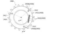
図29はバスバーを図示した斜視図であり、図30はバスバーの平面図であり、図31は図30のAA′断面図である。 Figure 29 is a perspective view of the busbar, Figure 30 is a plan view of the busbar, and Figure 31 is a cross-sectional view taken along line AA' in Figure 30.
図30を参照すると、バスバー2400は胴体2410と、ターミナル2420および突部2430を含むことができる。
Referring to FIG. 30, the
胴体2410はバスバー2400の外形をなす。胴体2410は環状のモールド部材であり得る。この時、胴体2410は絶縁材質からなり得る。胴体2410は複数のターミナル2420を絶縁させる。ターミナル2420は胴体2410に結合される。この時、ターミナル2420は第1ターミナル2421と第2ターミナル2422を含むことができる。
The
胴体2410は内部にホールが形成され得る。図31を参照すると、胴体2410は第1側面B1と第2側面B2を含むことができる。第1側面B1と第2側面B2は半径方向に離隔配置される。そして、第1側面B1は外側に向かい、第2側面B2は内側に向かう。そして、第2側面B2と胴体2410の上面の間には第3側面B3が配置される。第3側面B3は傾斜するように配置され得る。
The
胴体2410の上面にはガイド部材2411が配置され得る。ガイド部材2411は胴体2410の上面から軸方向に延長され得る。ガイド部材2411の内部に複数の第2ターミナル2422が配置され得る。複数の第2ターミナル2422は互いに離隔され得る。この時、第2ターミナル2422はガイド部材2411より軸方向に長く形成され得る。そして、第2ターミナル2422の上端はガイド部材2411の上端より高く配置され得る。複数の第2ターミナル2422とガイド部材2411はハウジング2500の上側に露出され得る。第1ターミナル2421と第2ターミナル2422は一体に形成され得る。第2ターミナル2422は第1ターミナル2421から垂直折り曲げられ得る。
A guide member 2411 may be disposed on the upper surface of the
図30を参照すると、胴体2410の上面には第1支持面2412が配置され得る。第1支持面2412は複数個であり得る。複数の第1支持面2412は互いに離隔され得る。複数の第1支持面2412は軸中心から離隔され得る。この時、複数の第1支持面2412は軸中心との離隔距離が互いに同一であり得る。複数の第1支持面2412は円周方向に互いにオーバーラップされ得る。第1支持面2412はハウジング2500と接触され得る。例えば第1支持面2412は第1パート2510と接触され得る。この時、第1パート2510には第1支持面2412の位置に対応する第2支持面2513が形成され得る。
Referring to FIG. 30, a
再び図3を参照すると、ターミナル2420は第1ターミナル2421と第2ターミナル2422を含むことができる。第1ターミナル2421と第2ターミナル2422はその形状および機能的特性によって区分されて説明され得るだけであって、互いに上下に連結された一つの部材であり得る。一方、第1ターミナル2421と第2ターミナル2422は別途の物であってもよい。この時、第1ターミナル2421と第2ターミナル2422は別途の物である場合にフュージングによって結合され得る。
Referring again to FIG. 3, the terminal 2420 may include a
第1ターミナル2421はコイル2330と電気的に連結され得る。第1ターミナル2421は複数個であり得る。複数の第1ターミナル2421は3個であり得る。複数の第1ターミナル2421は胴体2410に結合され得る。複数の第1ターミナル2421は胴体と突出部を含むことができる。胴体の軸中心を基準として環状に配置され得る。突出部は胴体の外側に連結され得る。一つの胴体に複数個の突出部が連結され得る。この時、胴体と突出部は一つの部材であり得る。そして、突出部は胴体2410の側面から露出され得る。この時、第1ターミナル2421とコイル2330の連結端がフュージングされて電気的に連結され得る。
The first terminal 2421 may be electrically connected to the
第2ターミナル2422は電源と連結される。そして、第2ターミナル2422は第1ターミナル2421と連結されて第1ターミナル2421に電源を印加する。第2ターミナル2422は複数個であり得る。複数の第2ターミナル2422は3個であり得る。3個の第2ターミナル2422はそれぞれU、V、W相の電源と連結され得る。複数の第2ターミナル2422は軸方向に長く延長され得る。複数の第2ターミナル2422は胴体2410の上面から突出され得る。
The
突部2430は胴体2410の上面に配置され得る。突部2430は胴体2410と射出によって結合され得る。突部2430は第1側面B1と第2側面B2の半径方向間に配置され得る。そして、突部2430は第3側面B3より外側に配置され得る。突部2430は第1側面B1と半径方向に距離をおいて配置され得る。そして、突部2430は第2側面B2とも半径方向に距離をおいて配置され得る。この時、突部2430は第2側面B2より第1側面B1に近く配置され得る。突部2430の端部面には第1支持面2412が配置され得る。第1支持面2412は第1パート2510と接触する。この時、突部2430の軸方向の長さだけ胴体2410と第1パート2510が離隔距離を維持することができる。
The
突部2430は複数個であり得る。複数の突部2430は端部面の高さが同一であってもよい。すなわち、複数の第1支持面2412は軸方向の高さが同一であってもよい。この時、第1支持面2412は第2ターミナル2422の上端より低く配置される。複数の突部2430は円周方向に沿って離隔され得る。複数の突部2430は等間隔で配置され得る。複数の突部2430は軸中心から離隔され得る。この時、複数の突部2430は軸中心との離隔距離が互いに同一であってもよい。複数の突部2430は円周方向に互いにオーバーラップされ得る。複数の突部2430は3個であり得る。3個の突部2430は軸中心を基準として120度間隔で離隔配置され得る。この時、第2ターミナル2422は3個の突部2430のうちいずれか一つ2430aと他の一つ2430bの円周方向の間に配置され得る。
The
図31は、図30のAA′断面図である。
図31を参照すると、突部2430は第1部材2431と第2部材2432を含むことができる。
FIG. 31 is a cross-sectional view taken along line AA' of FIG.
Referring to FIG. 31 , the
第1部材2431は胴体2410の上面から延長され得る。第1部材2431は胴体2410と同一の素材であり得る。第1部材2431と胴体2410は一体のモールディング部材であり得る。第1部材2431は内側に溝が形成され得る。そして、第1部材2431の溝には第2部材2432が配置され得る。第2部材2432は第1部材2431または胴体2410と異なる素材であり得る。この時、第2部材2432の端部面は第1部材2431の端部面より高く配置され得る。そして、第2部材2432の端部面は第1パート2510と接触され得る。この時、第2部材2432の端部面と第1パート2510が接触し、胴体2410は第1パート2510と離隔距離を有することができる。
The
図32は第1パートと第2パートを図示した図面であり、図33は図32の底面図である。 Figure 32 is a drawing illustrating the first and second parts, and Figure 33 is a bottom view of Figure 32.
図32を参照すると、第1パート2510と第2パート2520は一体であり得る。この時、第1パート2510は円板状であり得る。そして、第2パート2520は円筒状であり得る。第1パート2510は第2パート2520の内部に配置され得る。第2パート2520の下端部には締結部2521が形成され得る。この時、締結部2521に第3パート2530が締結され得る。そして、図32および図33を参照すると、第1パート2510は第1面A1と第2面A2を含むことができる。第1面A1と第2面A2は上下に配置される。この時、第1面A1はバスバー2400に向かう。そして、第2面A2は第1面A1の反対側に向かう。第1面A1は下側に向かい、第2面A2は上側に向かう。
Referring to FIG. 32, the
第1パート2510にはベアリングポケット部2511、複数のリブ2512、第2支持面2513およびホール2514が形成され得る。ベアリングポケット部2511は第1パート2510の中央に配置され得る。ベアリングポケット部2511の内側中央にはシャフトホールが形成され得る。この時、ベアリングポケット部2511は内部に上部ベアリングが配置され得る。上部ベアリングはシャフト2100の上端部を回転可能に支持する。
The
複数のリブ2512はベアリングポケット部2511と第2パート2520の半径方向の間に配置される。複数のリブ2512は軸中心を基準として放射状に配置され得る。複数のリブ2512は間の間隔が互いに異なり得る。複数のリブ2512のうちいずれか一つと他の一つの間にホール2514が配置され得る。ホール2514はガイド部材2411と第2ターミナル2422が通過され得る。
The plurality of
第2支持面2513は第1面A1に形成され得る。第2支持面2513は胴体2410の上側に配置され得る。第2支持面2513は胴体2410と軸方向にオーバーラップされ得る。第2支持面2513は複数個であり得る。複数の第2支持面2513は互いに離隔され得る。複数の第2支持面2513の間の離隔距離は複数のリブ2512の間の隔離距離より狭くてもよい。複数の第2支持面2513は軸方向の高さが同一である。第2支持面2513は平坦面であり得る。第2支持面2513はリブ2512と重なるように形成され得る。第2支持面2513はリブ2512より下側に突出され得る。一方、図面に図示してはいないが、第2支持面2513はリブ2512または第1面A1に比べて上側に凹入されてもよい。
The
複数の第2支持面2513は3個であり得る。3個の第2支持面2513は軸中心を基準として120度間隔で離隔配置され得る。3個の第2支持面2513はそれぞれ3個の第1支持面2412の位置に対応して形成される。そして、第2支持面2513の中の一つ2513aと他の一つ2513bの円周方向の間にホール2514が配置され得る。ホール2514はガイド部材2411の位置に対応して形成され得る。
The number of second support surfaces 2513 may be three. The three second support surfaces 2513 may be spaced apart at 120 degree intervals based on the axial center. The three second support surfaces 2513 are formed corresponding to the positions of the three first support surfaces 2412. A
第2支持面2513は第1支持面2412より広く形成され得る。第2支持面2513は円形であり得る。第1支持面2412は突部2430の端部面であり得る。第2支持面2513の直径は突部2430の端部面の直径より大きくてもよい。第2支持面2513の形状は円形の他にも多様な形状で設計変形可能である。この時、第2支持面2513の中心は第1支持面2412の中心と同一軸線上に配置され得る。一方、第2支持面2513の中心は第1支持面2412の中心と軸方向にずれて配置され得る。このため、ハウジング2500にバスバー2400が挿入されながら第2支持面2513の中心と突部2430の間に所定の誤差が発生しても、第2支持面2513と第1支持面2412は端部面は接触され得る。
The
図34は、バスバーと第1パートおよび第2パートの結合状態を図示した分解斜視図である。 Figure 34 is an exploded perspective view showing the connection between the busbar and the first and second parts.
図34を参照すると、第1パート2510と第2パート2520は円筒形の内部空間を形成する。この時、内部空間の上側は第1パート2510によって閉鎖され得る。そして、内部空間の下側は開放され得る。そして、内部空間にバスバー2400が挿入される。この時、バスバー2400は内部空間の上側に配置され得る。この時、突部2430と第2支持面2513が接触する。胴体2410と第1パート2510は離隔する。そして、第2ターミナル2422はホール2514を通過してハウジング2500から露出される。
Referring to FIG. 34, the
図35はバスバーと第1パートおよび第2パートが結合された状態を図示した側断面図であり、図36は図35のA領域を拡大した図面である。 Figure 35 is a side cross-sectional view showing the state in which the busbar is connected to the first and second parts, and Figure 36 is an enlarged drawing of area A in Figure 35.
図35を参照すると、突部2430の端部面は第2支持面2513と接触する。そして、 第1面Aの第2支持面2513は胴体2410の上面と軸方向に離隔する。そして、第2ターミナル2422は第1パート2510の上側に配置される。第2ターミナル2422は第1パート2510から一定の高さHに配置される。この時、突部2430の軸方向の長さH2によって第2ターミナル2422上端の高さHが決定され得る。この時、ハウジング2500から露出した第2ターミナル2422の高さHは、第2ターミナル2422の軸方向の長さH1から突部2430の軸方向の長さH2と、第1パート2510の厚さT1を差し引いたものと同一である。この時、突部2430の軸方向の長さH2を変更設計して第2ターミナル2422の高さを調節することができる。ここで、第2ターミナル2420は外部電源と連結され得る。このような本発明の実施例に係るモータは、ターミナルの電源連結部位を定位置に案内して累積公差によるターミナル電源連結部位の位置変化を防止することができる。
Referring to FIG. 35, the end surface of the
一方、図面に図示してはいないが、実施例に係るモータは、第1パート2510に複数の突部が形成され得る。この時、突部の軸方向の長さは第1パート2510と胴体2410の上面の軸方向距離と同一であってもよい。そして、突部の上面に第2支持面に配置され得る。また、胴体2410の上面には第2支持面と接触する複数の第1支持面が配置され得る。この時、胴体2410の上面と第1支持面の軸方向の高さは同一であってもよい。
Meanwhile, although not shown in the drawings, the motor according to the embodiment may have a plurality of protrusions formed on the
反面、実施例に係るモータは、バスバー2400に少なくとも一つの第1突部が形成され得る。そして、第1パート2510に第1突部の位置に対応する少なくとも一つの第2突部が形成され得る。この時、第1突部の端部面には第1支持面が配置され得る。また、第2突部の端部面には第2支持面が配置され得る。この時、第1突部と第2突部の軸方向の長さの和は第1パート2510と胴体2410の上面の軸方向距離と同一であってもよい。
On the other hand, in the motor according to the embodiment, at least one first protrusion may be formed on the
実施例に係るモータは、ハウジング内にバスバーが挿入される間、前記ハウジングの内面にバスバーが接触しながらバスバーを定位置に配置させることができる。そして、ターミナルの電源連結部位を定位置に案内して、累積公差によるターミナル電源連結部位の位置変化を防止することができる。したがって、電源ターミナルの接続不良によるモータの不良を低減することができる。 In the motor according to the embodiment, while the bus bar is being inserted into the housing, the bus bar can be placed in a fixed position by contacting the inner surface of the housing. In addition, the power connection part of the terminal can be guided to a fixed position, preventing the position of the terminal power connection part from changing due to cumulative tolerance. Therefore, it is possible to reduce motor defects due to poor connection of the power terminal.
前述された実施例にはインナーロータ型モータを例にして説明したが、これに限定されない。本発明はアウターロータ型モータにも適用可能である。また、車両用または家電用など、多様な機器に利用することができる。 The above embodiment has been described using an inner rotor type motor as an example, but is not limited to this. The present invention can also be applied to outer rotor type motors. In addition, the present invention can be used in a variety of devices, such as vehicles and home appliances.
Claims (10)
前記シャフトに結合されるロータ;
前記ロータの外側に配置されるステータ;
前記ステータの上側に配置されるバスバー;および
コイルと連結される前記バスバーと結合する電源ターミナル部を含み、
前記電源ターミナル部は第1溝を含み、
前記バスバーはバスバーボディと、前記バスバーボディに配置される複数のターミナルを含み、
前記バスバーボディは前記バスバーボディで上面から上側に突出して前記第1溝に配置される複数個の第1突起を含み、
複数個の前記第1突起は前記バスバーの中心を基準として同一の円形軌道上に配置され、
前記バスバーボディは第1バスバーボディと第2バスバーボディを含み、
前記第1バスバーボディの軸方向に上側に前記第2バスバーボディが多段の構造で配置され、
前記第2バスバーボディは、円周方向に幅を持つ空の空間が形成され、
前記第1突起は前記第2バスバーボディが形成する空き空間に配置される、モータ。 shaft;
a rotor coupled to the shaft;
a stator disposed outside the rotor;
A bus bar is disposed on an upper side of the stator; and a power terminal portion is coupled to the bus bar and is connected to a coil,
the power terminal portion includes a first groove;
The busbar includes a busbar body and a plurality of terminals disposed on the busbar body.
the busbar body includes a plurality of first protrusions protruding upward from an upper surface of the busbar body and disposed in the first grooves;
the first protrusions are arranged on the same circular path with respect to the center of the bus bar;
the busbar body includes a first busbar body and a second busbar body;
the second busbar body is arranged in a multi-stage structure above the first busbar body in the axial direction ,
The second bus bar body has an empty space having a width in a circumferential direction,
The first protrusion is disposed in an empty space formed by the second bus bar body.
前記シャフトと結合されたロータ;
前記ロータと対応するように配置され、ステータコアと、コイルを含むステータ;
前記ステータの上側に配置されるバスバー;
前記コイルと連結され、前記バスバーと結合する電源ターミナル部を含み、
前記電源ターミナル部は第2突起を含み、
前記バスバーはバスバーボディと、前記バスバーボディに配置される複数のターミナルを含み、
前記バスバーボディは前記バスバーボディで上面に配置されて前記第2突起が配置される複数個の第2溝を含み、
前記複数個の第2溝は前記バスバーの中心を基準として同一の円形軌道上に配置され、
前記バスバーボディは第1バスバーボディと第2バスバーボディを含み、
前記第1バスバーボディの軸方向に上側に前記第2バスバーボディが多段の構造で配置され、
前記第2バスバーボディは、円周方向に幅を持つ空の空間が形成され、
前記第2溝は前記第2バスバーボディが形成する空き空間に配置される、モータ。 shaft;
a rotor coupled to the shaft;
a stator arranged to correspond to the rotor and including a stator core and a coil;
A bus bar disposed on an upper side of the stator;
a power terminal portion connected to the coil and coupled to the bus bar;
the power terminal portion includes a second protrusion,
The busbar includes a busbar body and a plurality of terminals disposed on the busbar body.
the busbar body includes a plurality of second grooves disposed on an upper surface of the busbar body and in which the second protrusions are disposed,
the second grooves are arranged on the same circular track with respect to the center of the bus bar;
the busbar body includes a first busbar body and a second busbar body;
the second busbar body is arranged in a multi-stage structure above the first busbar body in the axial direction ,
The second bus bar body has an empty space having a width in a circumferential direction,
The second groove is disposed in an empty space formed by the second bus bar body.
前記バスバーは第1ターミナルが配置される第1バスバーボディと前記第1バスバーボディの上側に配置されて第2ターミナルが配置される第2バスバーボディを含み、
前記第1バスバーボディの上面に複数の第1結合部を含み、
前記電源ターミナル部ボディの下面に前記第1結合部と結合する複数の第2結合部を含み、
前記第2ターミナルと前記複数の電源ターミナルが連結される、請求項1または請求項4に記載のモータ。 a power terminal unit including a power terminal unit body and a plurality of power terminals disposed in the power terminal unit body;
the busbar includes a first busbar body in which a first terminal is disposed, and a second busbar body disposed above the first busbar body in which a second terminal is disposed,
a first busbar body including a first coupling portion on an upper surface of the first busbar body;
a plurality of second coupling parts coupled to the first coupling parts on a lower surface of the power terminal body;
The motor according to claim 1 or 4, wherein the second terminal and the plurality of power supply terminals are coupled together.
前記ハウジングは前記バスバーの上側に配置される第1パートを含み、
前記バスバーは前記第1パートと接触する少なくとも一つの第1支持面を含み、
前記第1パートは前記第1支持面とそれぞれ接触される少なくとも一つの第2支持面を含む、請求項1に記載のモータ。 a housing for receiving the stator and the busbars;
the housing includes a first part disposed above the bus bar;
the busbar includes at least one first support surface in contact with the first part;
The motor of claim 1 , wherein the first part includes at least one second support surface in contact with each of the first support surfaces.
前記第2支持面は前記第1バスバーボディの上面より高く、前記第2ターミナルの上端より低く配置される、請求項6に記載のモータ。 a first terminal is disposed on the first busbar body, and a second terminal is disposed on the second busbar body;
The motor of claim 6 , wherein the second support surface is disposed higher than a top surface of the first busbar body and lower than a top end of the second terminal.
前記第1バスバーボディから延びる第1部材と、
前記第1部材の内側に配置される第2部材を含む、請求項6に記載のモータ。 the first projection includes a first member extending from the first busbar body ;
The motor of claim 6 including a second member disposed inwardly of the first member.
前記第2部材の端部面に前記第2支持面に配置される、請求項8に記載のモータ。 The end surface of the second member is disposed higher than the end surface of the first member,
The motor of claim 8 , wherein the second support surface is disposed on an end surface of the second member.
前記第2部材は前記第1部材と異なる素材である、請求項8に記載のモータ。 the first member is made of the same material as the first busbar body ,
The motor of claim 8 , wherein the second member is a different material than the first member.
Applications Claiming Priority (5)
| Application Number | Priority Date | Filing Date | Title |
|---|---|---|---|
| KR1020200022316A KR102796036B1 (en) | 2020-02-24 | 2020-02-24 | Motor |
| KR10-2020-0022316 | 2020-02-24 | ||
| KR10-2020-0033328 | 2020-03-18 | ||
| KR1020200033328A KR102896997B1 (en) | 2020-03-18 | 2020-03-18 | Motor |
| PCT/KR2021/001016 WO2021172770A1 (en) | 2020-02-24 | 2021-01-26 | Motor |
Publications (2)
| Publication Number | Publication Date |
|---|---|
| JP2023516570A JP2023516570A (en) | 2023-04-20 |
| JP7655929B2 true JP7655929B2 (en) | 2025-04-02 |
Family
ID=77491922
Family Applications (1)
| Application Number | Title | Priority Date | Filing Date |
|---|---|---|---|
| JP2022549942A Active JP7655929B2 (en) | 2020-02-24 | 2021-01-26 | Motor |
Country Status (5)
| Country | Link |
|---|---|
| US (1) | US12506379B2 (en) |
| EP (1) | EP4113804A4 (en) |
| JP (1) | JP7655929B2 (en) |
| CN (1) | CN115152132B (en) |
| WO (1) | WO2021172770A1 (en) |
Citations (3)
| Publication number | Priority date | Publication date | Assignee | Title |
|---|---|---|---|---|
| US20120112582A1 (en) | 2010-11-05 | 2012-05-10 | Lg Innotek Co., Ltd. | Bus bar of eps motor |
| JP2017085756A (en) | 2015-10-27 | 2017-05-18 | 株式会社ミツバ | motor |
| JP2019068508A (en) | 2017-09-28 | 2019-04-25 | 日本電産株式会社 | Busbar unit and motor |
Family Cites Families (16)
| Publication number | Priority date | Publication date | Assignee | Title |
|---|---|---|---|---|
| JP5703604B2 (en) * | 2010-03-03 | 2015-04-22 | 日本電産株式会社 | Bus bar unit and motor |
| JP6098920B2 (en) * | 2012-10-19 | 2017-03-22 | 日本電産株式会社 | Stator unit and motor |
| JP6155057B2 (en) * | 2013-03-08 | 2017-06-28 | Kyb株式会社 | Busbar unit manufacturing method and busbar unit |
| JP6248251B2 (en) * | 2013-11-29 | 2017-12-20 | 多摩川精機株式会社 | Outer rotor type rotation sensor signal lead-out structure |
| US9755376B2 (en) * | 2013-12-11 | 2017-09-05 | Lg Innotek Co., Ltd. | Motor terminal, motor terminal assembly having the same, and method of assembling motor using the same |
| JP6368936B2 (en) * | 2014-09-30 | 2018-08-08 | 日本電産株式会社 | motor |
| JP6596884B2 (en) * | 2015-03-31 | 2019-10-30 | 日本電産株式会社 | motor |
| KR102353916B1 (en) * | 2015-04-15 | 2022-01-21 | 엘지이노텍 주식회사 | Terminal asembly for motor and Motor using the same |
| KR102529820B1 (en) | 2015-11-03 | 2023-05-08 | 엘지이노텍 주식회사 | Motor |
| US10910924B2 (en) * | 2016-08-12 | 2021-02-02 | Nidec Corporation | Motor |
| JP2018125951A (en) * | 2017-01-31 | 2018-08-09 | 日本電産株式会社 | Motor and air blowing device with the same |
| DE112018001656T5 (en) | 2017-03-31 | 2020-01-02 | Nidec Corporation | Busbar unit and motor that has it |
| KR102343086B1 (en) * | 2017-04-26 | 2021-12-24 | 엘지이노텍 주식회사 | Motor |
| US11355989B2 (en) * | 2017-10-31 | 2022-06-07 | Lg Innotek Co., Ltd. | Bus bar and motor comprising same |
| KR102437465B1 (en) * | 2017-10-31 | 2022-08-29 | 엘지이노텍 주식회사 | Busbar and motor having the same |
| JP7155518B2 (en) * | 2017-12-21 | 2022-10-19 | 日本電産トーソク株式会社 | electric oil pump |
-
2021
- 2021-01-26 WO PCT/KR2021/001016 patent/WO2021172770A1/en not_active Ceased
- 2021-01-26 JP JP2022549942A patent/JP7655929B2/en active Active
- 2021-01-26 EP EP21760383.6A patent/EP4113804A4/en active Pending
- 2021-01-26 CN CN202180016381.0A patent/CN115152132B/en active Active
- 2021-01-26 US US17/904,885 patent/US12506379B2/en active Active
Patent Citations (3)
| Publication number | Priority date | Publication date | Assignee | Title |
|---|---|---|---|---|
| US20120112582A1 (en) | 2010-11-05 | 2012-05-10 | Lg Innotek Co., Ltd. | Bus bar of eps motor |
| JP2017085756A (en) | 2015-10-27 | 2017-05-18 | 株式会社ミツバ | motor |
| JP2019068508A (en) | 2017-09-28 | 2019-04-25 | 日本電産株式会社 | Busbar unit and motor |
Also Published As
| Publication number | Publication date |
|---|---|
| WO2021172770A1 (en) | 2021-09-02 |
| JP2023516570A (en) | 2023-04-20 |
| EP4113804A4 (en) | 2024-03-27 |
| US12506379B2 (en) | 2025-12-23 |
| EP4113804A1 (en) | 2023-01-04 |
| CN115152132A (en) | 2022-10-04 |
| CN115152132B (en) | 2025-08-26 |
| US20230024882A1 (en) | 2023-01-26 |
Similar Documents
| Publication | Publication Date | Title |
|---|---|---|
| US9000629B2 (en) | Stator segment and motor | |
| CN104541437B (en) | Stator unit and motor | |
| CN111295819B (en) | Bus bar and motor including the same | |
| US20120286593A1 (en) | Stator and motor | |
| CN114128086B (en) | Split core assembly and stator including same | |
| CN109075654B (en) | Power supply terminal and motor comprising same | |
| JP2015046960A (en) | Power collection / retention member holding structure, electric motor, and electric motor manufacturing method | |
| JP7478152B2 (en) | motor | |
| JP4224649B2 (en) | Insulated housing for three-phase AC motor | |
| KR20190048470A (en) | Busbar and motor having the same | |
| KR102355647B1 (en) | Stator and motor having the same | |
| CN115176400A (en) | Motor | |
| EP3846320A1 (en) | Motor | |
| JP7655929B2 (en) | Motor | |
| JP2025188240A (en) | Bus bar and motor including the same | |
| CN116724477A (en) | motor | |
| CN114556755B (en) | Motor | |
| JP7222999B2 (en) | Rotor and motor equipped with it | |
| KR20230083621A (en) | Motor | |
| KR102819660B1 (en) | Motor | |
| KR102896997B1 (en) | Motor | |
| US20240388160A1 (en) | Motor | |
| US12381435B2 (en) | Motor | |
| JP2022552529A (en) | motor | |
| KR20230100980A (en) | Motor |
Legal Events
| Date | Code | Title | Description |
|---|---|---|---|
| A521 | Request for written amendment filed |
Free format text: JAPANESE INTERMEDIATE CODE: A523 Effective date: 20220825 |
|
| A621 | Written request for application examination |
Free format text: JAPANESE INTERMEDIATE CODE: A621 Effective date: 20231030 |
|
| A131 | Notification of reasons for refusal |
Free format text: JAPANESE INTERMEDIATE CODE: A131 Effective date: 20240910 |
|
| A977 | Report on retrieval |
Free format text: JAPANESE INTERMEDIATE CODE: A971007 Effective date: 20240911 |
|
| A521 | Request for written amendment filed |
Free format text: JAPANESE INTERMEDIATE CODE: A523 Effective date: 20241205 |
|
| TRDD | Decision of grant or rejection written | ||
| A01 | Written decision to grant a patent or to grant a registration (utility model) |
Free format text: JAPANESE INTERMEDIATE CODE: A01 Effective date: 20250311 |
|
| A61 | First payment of annual fees (during grant procedure) |
Free format text: JAPANESE INTERMEDIATE CODE: A61 Effective date: 20250321 |
|
| R150 | Certificate of patent or registration of utility model |
Ref document number: 7655929 Country of ref document: JP Free format text: JAPANESE INTERMEDIATE CODE: R150 |