JP7657331B2 - Nonlinear resistance resin material, nonlinear resistor, overvoltage protection device, and method for producing nonlinear resistance resin material - Google Patents
Nonlinear resistance resin material, nonlinear resistor, overvoltage protection device, and method for producing nonlinear resistance resin material Download PDFInfo
- Publication number
- JP7657331B2 JP7657331B2 JP2023575151A JP2023575151A JP7657331B2 JP 7657331 B2 JP7657331 B2 JP 7657331B2 JP 2023575151 A JP2023575151 A JP 2023575151A JP 2023575151 A JP2023575151 A JP 2023575151A JP 7657331 B2 JP7657331 B2 JP 7657331B2
- Authority
- JP
- Japan
- Prior art keywords
- particles
- nonlinear resistance
- resin material
- resistance resin
- nonlinear
- Prior art date
- Legal status (The legal status is an assumption and is not a legal conclusion. Google has not performed a legal analysis and makes no representation as to the accuracy of the status listed.)
- Active
Links
Images




Classifications
-
- H—ELECTRICITY
- H01—ELECTRIC ELEMENTS
- H01C—RESISTORS
- H01C7/00—Non-adjustable resistors formed as one or more layers or coatings; Non-adjustable resistors made from powdered conducting material or powdered semi-conducting material with or without insulating material
- H01C7/10—Non-adjustable resistors formed as one or more layers or coatings; Non-adjustable resistors made from powdered conducting material or powdered semi-conducting material with or without insulating material voltage responsive, i.e. varistors
- H01C7/12—Overvoltage protection resistors; Arresters
-
- H—ELECTRICITY
- H01—ELECTRIC ELEMENTS
- H01C—RESISTORS
- H01C17/00—Apparatus or processes specially adapted for manufacturing resistors
- H01C17/06—Apparatus or processes specially adapted for manufacturing resistors adapted for coating resistive material on a base
- H01C17/065—Apparatus or processes specially adapted for manufacturing resistors adapted for coating resistive material on a base by thick film techniques, e.g. serigraphy
- H01C17/06506—Precursor compositions therefor, e.g. pastes, inks, glass frits or green body
- H01C17/06573—Precursor compositions therefor, e.g. pastes, inks, glass frits or green body characterised by the permanent binder
- H01C17/06586—Precursor compositions therefor, e.g. pastes, inks, glass frits or green body characterised by the permanent binder composed of organic material
-
- H—ELECTRICITY
- H01—ELECTRIC ELEMENTS
- H01C—RESISTORS
- H01C7/00—Non-adjustable resistors formed as one or more layers or coatings; Non-adjustable resistors made from powdered conducting material or powdered semi-conducting material with or without insulating material
- H01C7/10—Non-adjustable resistors formed as one or more layers or coatings; Non-adjustable resistors made from powdered conducting material or powdered semi-conducting material with or without insulating material voltage responsive, i.e. varistors
-
- H—ELECTRICITY
- H01—ELECTRIC ELEMENTS
- H01C—RESISTORS
- H01C7/00—Non-adjustable resistors formed as one or more layers or coatings; Non-adjustable resistors made from powdered conducting material or powdered semi-conducting material with or without insulating material
- H01C7/10—Non-adjustable resistors formed as one or more layers or coatings; Non-adjustable resistors made from powdered conducting material or powdered semi-conducting material with or without insulating material voltage responsive, i.e. varistors
- H01C7/1006—Thick film varistors
-
- H—ELECTRICITY
- H01—ELECTRIC ELEMENTS
- H01C—RESISTORS
- H01C7/00—Non-adjustable resistors formed as one or more layers or coatings; Non-adjustable resistors made from powdered conducting material or powdered semi-conducting material with or without insulating material
- H01C7/10—Non-adjustable resistors formed as one or more layers or coatings; Non-adjustable resistors made from powdered conducting material or powdered semi-conducting material with or without insulating material voltage responsive, i.e. varistors
- H01C7/105—Varistor cores
- H01C7/108—Metal oxide
- H01C7/112—ZnO type
-
- H—ELECTRICITY
- H01—ELECTRIC ELEMENTS
- H01C—RESISTORS
- H01C7/00—Non-adjustable resistors formed as one or more layers or coatings; Non-adjustable resistors made from powdered conducting material or powdered semi-conducting material with or without insulating material
- H01C7/10—Non-adjustable resistors formed as one or more layers or coatings; Non-adjustable resistors made from powdered conducting material or powdered semi-conducting material with or without insulating material voltage responsive, i.e. varistors
- H01C7/105—Varistor cores
- H01C7/118—Carbide, e.g. SiC type
Landscapes
- Engineering & Computer Science (AREA)
- Microelectronics & Electronic Packaging (AREA)
- Physics & Mathematics (AREA)
- Electromagnetism (AREA)
- Manufacturing & Machinery (AREA)
- Thermistors And Varistors (AREA)
Description
本開示は、非線形抵抗特性を有する非線形抵抗樹脂材料、この非線形抵抗樹脂材料を用いた非線形抵抗体、この非線形抵抗体を備える過電圧保護装置および非線形抵抗樹脂材料の製造方法に関する。The present disclosure relates to a nonlinear resistance resin material having nonlinear resistance characteristics, a nonlinear resistor using this nonlinear resistance resin material, an overvoltage protection device including this nonlinear resistor, and a method for manufacturing the nonlinear resistance resin material.
従来、高電界部分を有する機器においては、電界が許容値を下回るように設計が行われている。電界が許容値よりも小さければ小さいほど、絶縁距離を縮めることができるため、機器の小型化を進めることができる。そのため、電界を緩和することは、機器の小型化に繋がる。 Traditionally, devices with high electric field parts are designed to keep the electric field below the allowable value. The smaller the electric field is below the allowable value, the shorter the insulation distance can be, which allows for the miniaturization of the device. Therefore, reducing the electric field leads to the miniaturization of the device.
従来、電界を緩和する技術として、閾値未満の電圧が印加されると絶縁性を示し閾値以上の電圧が印加されると導電性を示す非線形抵抗特性を有する非線形抵抗樹脂材料を機器の高電界部分に配置する技術が知られている。このような非線形抵抗樹脂材料として、例えば、特許文献1には、非線形抵抗特性を有する粒子に半導電性ウィスカと1種類の樹脂とを配合した電界緩和剤が開示されている。A conventional technique for alleviating electric fields involves placing a nonlinear resistance resin material in the high electric field area of a device, the nonlinear resistance resin material having nonlinear resistance properties that are insulating when a voltage below a threshold is applied and conductive when a voltage equal to or greater than the threshold is applied. For example,
特許文献1に開示された電界緩和剤では、半導電性ウィスカが樹脂全体に分散しているため、十分な導電性を得るためには、多量の半導電性ウィスカを添加する必要がある。しかし、半導電性ウィスカの添加量が増えれば増えるほど、半導電性ウィスカが連なりやすくなり、厚み方向に通電しやすくなる。これにより、設計上の非線形抵抗特性より抵抗値が低下してしまい、電界緩和剤が絶縁体として機能すべき条件で絶縁体としての機能が低下するおそれがある。なお、厚み方向とは、XYZ座標のZ方向を意味し、例えば、非線形抵抗樹脂材料にプレス加工を行った場合のプレス方向であり、非線形抵抗樹脂材料を塗工した場合の非線形抵抗樹脂材料の膜厚の厚み方向である。In the electric field relaxation agent disclosed in
本開示は、上記に鑑みてなされたものであって、絶縁体として機能すべき条件で絶縁体としての機能の低下を防ぐことができる非線形抵抗樹脂材料を得ることを目的とする。The present disclosure has been made in consideration of the above, and aims to obtain a nonlinear resistance resin material that can prevent a decrease in its function as an insulator under conditions in which it should function as an insulator.
上述した課題を解決し、目的を達成するために、本開示にかかる非線形抵抗樹脂材料は、閾値未満の電圧が印加されると絶縁性を示し閾値以上の電圧が印加されると導電性を示す非線形抵抗特性を有する複数の第1の粒子と、半導電性または導電性の第2の粒子を含み、複数の第1の粒子のうちの一部または全部の表面の少なくとも一部を覆う第1の樹脂相と、第1の粒子および第1の樹脂相以外の部分に形成される空隙を埋めるとともに絶縁性を有する第2の樹脂相と、を備えている。隣り合う第1の粒子同士は、第1の樹脂相を介して互いに結着されるとともに電気的に接続されている。In order to solve the above-mentioned problems and achieve the object, the nonlinear resistance resin material according to the present disclosure includes a plurality of first particles having nonlinear resistance characteristics that exhibit insulating properties when a voltage below a threshold is applied and exhibiting conductive properties when a voltage equal to or greater than the threshold is applied, a first resin phase that includes semiconductive or conductive second particles and covers at least a portion of the surfaces of some or all of the plurality of first particles, and a second resin phase that fills voids formed in portions other than the first particles and the first resin phase and has insulating properties. Adjacent first particles are bonded to each other and electrically connected via the first resin phase.
本開示によれば、絶縁体として機能すべき条件で絶縁体としての機能の低下を防ぐことができるという効果を奏する。 The present disclosure has the effect of preventing deterioration of the insulator's function under conditions in which it should function as an insulator.
以下に、実施の形態にかかる非線形抵抗樹脂材料、非線形抵抗体、過電圧保護装置および非線形抵抗樹脂材料の製造方法を図面に基づいて詳細に説明する。 Below, the nonlinear resistive resin material, nonlinear resistor, overvoltage protection device, and method for manufacturing the nonlinear resistive resin material according to the embodiments are described in detail with reference to the drawings.
実施の形態1.
図1は、実施の形態1にかかる非線形抵抗樹脂材料1を模式的に示した図である。図2は、図1に示されるA部の拡大図である。図1に示すように、非線形抵抗樹脂材料1は、複数の第1の粒子2と、複数の第1の粒子2のうちの一部または全部の表面を覆う第1の樹脂相3とを備えている。第1の樹脂相3は、本実施の形態では複数の第1の粒子2のうちの全部の表面を覆っている。隣り合う第1の粒子2同士は、第1の樹脂相3を介して互いに結着されるとともに電気的に接続されている。非線形抵抗樹脂材料1のうち第1の粒子2および第1の樹脂相3以外の部分には、空隙4が形成されている。空隙4は、非線形抵抗樹脂材料1の外縁と第1の粒子2との間に形成されている。また、図2に示すように、空隙4は、隣り合う3つの第1の粒子2で囲まれた部分に形成されている。なお、図1では、同じ粒径の第1の粒子2が規則正しく整列した状態を図示しているが、複数の粒度分布を有する第1の粒子2を用いた場合には、大小様々な第1の粒子2が密に結着した状態になる。
FIG. 1 is a schematic diagram of a nonlinear
図3は、実施の形態1における第1の粒子2と第1の樹脂相3とを模式的に示した図である。図4は、図3に示されるB部の拡大図である。図3に示される第1の粒子2は、閾値未満の電圧が印加されると絶縁性を示し閾値以上の電圧が印加されると導電性を示す非線形抵抗特性を有する。すなわち、第1の粒子2は、閾値電圧Vthを境として、絶縁体と導電体とに可逆的に変化する特性を有している。そのため、一般的な材料はオームの法則に従うのに対し、第1の粒子2はオームの法則に従わず、通称「バリスタ」と呼ばれる。特に、第1の粒子2のような粒子形状のバリスタは、「マイクロバリスタ」と呼ばれる。
FIG. 3 is a diagram showing a schematic diagram of the
図5は、実施の形態1にかかる非線形抵抗樹脂材料1の第1の粒子2の電流-電圧特性と、絶縁体に近い状態の材料の電流-電圧特性と、導電体に近い状態の材料の電流-電圧特性とを示した図である。図5の横軸は電流(A)であり、縦軸は電圧(V)である。図5に示される線L1は、第1の粒子2の電流-電圧特性を表している。図5に示される線L2は、絶縁体に近い状態の材料の電流-電圧特性を表している。図5に示される線L3は、導電体に近い状態の材料の電流-電圧特性を表している。
Figure 5 is a diagram showing the current-voltage characteristics of the
図5に示すように、第1の粒子2は、図5中のドットハッチングで表された小電流領域Rを超えたところにある閾値電圧Vthを境として、電気抵抗が変わり、急激に電流が流れることが分かる。すなわち、第1の粒子2は、印加される電圧が閾値電圧Vthよりも小さいと絶縁性を示すが、印加される電圧が閾値電圧Vthよりも大きいと電気抵抗値が急激に減少し、導電性を示す。第1の粒子2の電流-電圧特性は、オームの法則に従う絶縁体に近い状態および導電体に近い状態の電流-電圧特性とは異なることが分かる。
As shown in Fig. 5, it can be seen that the electrical resistance of the
本開示において非線形抵抗特性を数値化した非線形抵抗指数は、閾値電圧Vthにおいて電気抵抗が急激に変わるときの程度を表し、電流-電圧特性の2点の傾きより求められ、一般的に下記の式(1)で表される。
非線形抵抗指数=(logI2-logI1)/(logV2-logV1)・・・(1)
In the present disclosure, the nonlinear resistance index, which is a numerical representation of the nonlinear resistance characteristic, represents the degree to which the electrical resistance changes suddenly at the threshold voltage Vth , and is calculated from the slope of two points of the current-voltage characteristic, and is generally expressed by the following formula (1).
Nonlinear resistance index=(logI 2 -logI 1 )/(logV 2 -logV 1 )...(1)
非線形抵抗特性が良いほど非線形抵抗指数は大きくなる。図5中の線L1に示される第1の粒子2のような閾値電圧Vthを境として急激に電流が流れる場合は、非線形抵抗特性が良く非線形抵抗指数は大きいと言える。一方で、図5中の線L2に示される非線形抵抗特性が小さく絶縁体に近い状態の材料では、非線形抵抗特性が悪く非線形抵抗指数が小さいと言える。また、図5中の線L3に示される非線形抵抗特性がなく導電体に近い状態の材料では、非線形抵抗特性がなく非線形抵抗指数が小さいと言える。
The better the nonlinear resistance characteristics, the larger the nonlinear resistance index. In the case where a current flows suddenly at the threshold voltage Vth as in the case of the
図3に示される第1の粒子2には、主成分に、数種類の副成分を微量添加して焼成した材料が用いられる。第1の粒子2の組成によって、閾値電圧Vthの大きさ、絶縁体のときの体積抵抗、非線形抵抗特性といった性能をコントロールすることができる。第1の粒子2の主成分には、例えば、酸化亜鉛または炭化ケイ素が用いられる。第1の粒子2の非線形抵抗特性を十分に確保する観点から、第1の粒子2は、酸化亜鉛または炭化ケイ素を80wt%以上含むことが好ましい。第1の粒子2の主成分には、炭化ケイ素に比べて非線形抵抗特性が高い酸化亜鉛を用いることが好ましい。第1の粒子2の副成分としては、例えば、酸化ビスマス、酸化アンチモン、酸化クロム、酸化ニッケル、酸化マンガン、酸化コバルト、酸化ケイ素が挙げられ、用途に応じて組成を調整する。
For the
ここで、第1の粒子2の製造方法について説明する。第1の粒子2の主成分を酸化亜鉛粉末とする場合を想定する。まず、主成分となる酸化亜鉛粉末95.8mol%を秤量する。次に、副成分として、酸化ビスマス0.5mol%、酸化アンチモン1.2mol%、酸化クロム0.5mol%、酸化ニッケル0.5mol%、酸化マンガン0.5mol%、酸化コバルト0.5mol%、酸化ケイ素0.5mol%を秤量し、秤量した副成分を酸化亜鉛粉末に添加する。これらの原料を、水を媒体として粉砕するとともに混合する。このとき、原料が均一にかつ同じ平均粒径となるように、原料を粉砕するとともに混合することが好ましい。続いて、粉砕かつ混合した原料を100℃以上の高温の雰囲気にスプレー噴射して、原料を噴霧乾燥させる。これにより、酸化亜鉛粉末、酸化ビスマス、酸化アンチモン、酸化クロム、酸化ニッケル、酸化マンガン、酸化コバルト、酸化ケイ素などの原料が均一に凝集した球状の顆粒が得られる。続いて、顆粒を匣鉢に入れて1200℃の温度で焼成する。焼成した後の顆粒は、凝集しているため、凝集を解す圧力を加えて解砕を行う。以上の工程により、非線形抵抗特性を有する第1の粒子2が得られる。Here, a method for producing the
第1の粒子2は、酸化亜鉛または炭化ケイ素の1次粒子が集まった球状をしており、実際には微小な凹凸は見られるものの概ね球状である。第1の粒子2の粒径は、水を媒体として粉砕かつ混合するときの固形分濃度、スプレー噴射するときの圧力などにより調整可能であり、非線形抵抗樹脂材料1の用途に合わせて適宜変更すればよい。第1の粒子2の主成分を構成する1次粒子の平均粒径は、非線形抵抗特性となる閾値電圧Vthの大きさ、第1の樹脂相3との密着力の観点から、20μm未満であることが好ましい。
The
第1の粒子2には、球状が一部破砕された酸化亜鉛または炭化ケイ素が用いられてもよい。一部破砕とは、酸化亜鉛または炭化ケイ素が1次粒子まで粉砕されることなく、酸化亜鉛または炭化ケイ素の1次粒子の凝集が残っている状態を意味する。言い換えると、第1の粒子2は、2つ以上の1次粒子の凝集体であってもよい。このような第1の粒子2を用いると、球状の第1の粒子2を使用した場合に比べて、非線形抵抗特性については劣るものの、製造時の解砕処理時の圧力の自由度が増すため、第1の粒子2の生産性の向上を図ることができる。また、第1の粒子2には、部分的に凝集が解れていない酸化亜鉛または炭化ケイ素が用いられてもよい。このような第1の粒子2を用いても、製造時の解砕処理時の圧力の自由度が増すため、第1の粒子2の生産性の向上を図ることができる。ただし、一部破砕された酸化亜鉛または炭化ケイ素、あるいは、部分的に凝集が解れていない酸化亜鉛または炭化ケイ素を用いると、樹脂との混合時の粘度が上がるため、第1の粒子2に用いる酸化亜鉛または炭化ケイ素は、非線形抵抗樹脂材料1の用途に応じて適宜選択すればよい。For the
図3に示される第1の樹脂相3は、各第1の粒子2の表面の少なくとも一部を覆うとともに半導電性または導電性を有する。図4に示すように、第1の樹脂相3は、第1のマトリックス樹脂31と、導電性または半導電性を有する複数の第2の粒子32とを含有している。The
第1のマトリックス樹脂31には、溶媒に不溶な樹脂が用いられてもよいが、ポリビニルアルコール樹脂、ポリビニルブチラール、ポリ乳酸などの溶媒に可溶な樹脂が用いられるのが好ましい。例えば、ポリビニルアルコール樹脂の溶媒には水、ポリビニルブチラールの溶媒にはエタノール、ポリ乳酸の溶媒にはクロロホルムが使用できる。溶媒の安全性および作業性の観点から、第1のマトリックス樹脂31にはポリビニルアルコール樹脂を用いるのが好ましい。本実施の形態では、第1のマトリックス樹脂31にポリビニルアルコール樹脂を使用した。
For the
第2の粒子32には、例えば、金属粉末、カーボン粉末、導電性セラミック粉末が用いられる。混合のしやすさの観点から第2の粒子32にはカーボン粉末を用いるのが好ましい。本実施の形態では、第2の粒子32にカーボン粉末を使用した。For example, metal powder, carbon powder, or conductive ceramic powder is used for the
第1の樹脂相3は、図3に示されるように第1の粒子2の表面全体を覆っていてもよいが、必ずしも第1の粒子2の表面全体を覆う必要はなく第1の粒子2の表面の少なくとも一部を覆っていてもよい。第1の樹脂相3は、隣り合う第1の粒子2同士を後工程で結着させる観点から、第1の粒子2の表面の50%以上を覆っていることが好ましく、第1の粒子2の表面の70%以上を覆っているとより好ましい。第2の粒子32の平均粒径は、第1の粒子2の平均粒径の1/10以下であることが好ましい。このような大小関係にすると、第2の粒子32で第1の粒子2の表面を覆いやすくなる。
The
図2に示すように、各第1の粒子2は、第1の樹脂相3を介して隣の第1の粒子2に接触する接触部21と、隣の第1の粒子2に接触しない非接触部22とを有している。接触部21は、第1の樹脂相3を介して隣の第1の粒子2に電気的に接続される部分である。本明細書において「電気的に接続」とは、隣り合う第1の粒子2同士が第1の樹脂相3を介して導通している状態を意味する。隣り合う第1の粒子2の接触部21同士は、第1の樹脂相3を介して互いに結着されている。本明細書において「結着」とは、隣り合う第1の粒子2のそれぞれに第1の樹脂相3が密着しながら硬化することにより、隣り合う第1の粒子2同士が第1の樹脂相3を介して繋がっていることを意味する。第1の樹脂相3は、第1の粒子2の微小な凹凸に入り込み、アンカー効果のような物理的な結合で第1の粒子2に付いている場合もあれば、吸湿による水分の影響により水素結合のような化学的な結合で第1の粒子2に付いている場合もある。隣り合う第1の粒子2の接触部21同士の間には、薄い状態の第1の樹脂相3が存在する。As shown in FIG. 2, each
非線形抵抗樹脂材料1に占める第1の粒子2の体積割合が小さいと、第1の粒子2同士の結着が容易ではなくなる。そのため、第1の粒子2同士の結着のしやすさと最密充填の観点から、非線形抵抗樹脂材料1に占める第1の粒子2の体積割合は、25vol%以上74vol%以下であることが好ましい。第1の樹脂相3に占める第2の粒子32の体積割合が1vol%未満であると、導通する成分が不足することにより第1の粒子2同士の密着が不十分となり絶縁体に近づく可能性がある。一方で、第1の樹脂相3に占める第2の粒子32の体積割合が40vol%を超えると、導通する成分が過剰となり、導電体に近づく可能性がある。そのため、第1の樹脂相3に占める第2の粒子32の体積割合は、1vol%以上40vol%以下であることが好ましい。また、非線形抵抗樹脂材料1に占める第2の粒子32の体積割合は、0.2vol%以上2vol%以下であることが好ましい。非線形抵抗樹脂材料1に占める空隙4の体積は、非線形抵抗樹脂材料1に占める第1の樹脂相3の体積よりも大きいことが好ましい。If the volume ratio of the
次に、図1から図4を参照して、本実施の形態にかかる非線形抵抗樹脂材料1の製造方法について説明する。非線形抵抗樹脂材料1の製造方法は、混合工程と、加圧成形工程と、硬化工程とを含んでいる。なお、これらの工程は一例であり、非線形抵抗樹脂材料1の製造方法を限定する趣旨ではない。Next, a method for manufacturing the nonlinear
混合工程は、閾値未満の電圧が印加されると絶縁性を示し閾値以上の電圧が印加されると導電性を示す非線形抵抗特性を有する複数の第1の粒子2と、半導電性または導電性を有する第1の樹脂相3とを混合して、第1の樹脂相3で複数の第1の粒子2のうちの一部または全部の表面の少なくとも一部を覆う工程である。混合工程では、まず図3に示される第1の粒子2と図4に示される第1のマトリックス樹脂31であるポリビニルアルコール樹脂と第2の粒子32であるカーボン粉末とを秤量した後に混合する。本実施の形態では、ポリビニルアルコール樹脂には、三菱ケミカル株式会社製「GL-05」を使用した。本実施の形態では、カーボン粉末には、株式会社高純度化学研究所製「CCE03PB」を使用した。混合方法は、特に限定されず、公知の混合方法の中から適宜選択すればよい。本実施の形態では、機械を用いて第1の粒子2と、5wt%水溶液とした液体状態の第1のマトリックス樹脂31と、第2の粒子32とを均一に混合した。第1の粒子2が潰れないように混合する際の圧力をコントロールすることが好ましい。混合工程により、図1に示される第1の樹脂相3で覆われた第1の粒子2を備え、かつ、成形前の非線形抵抗樹脂材料1を得られる。The mixing process is a process in which a plurality of
加圧成形工程は、第1の樹脂相3で覆われた第1の粒子2を備える非線形抵抗樹脂材料1を所定の形状に成形する工程である。成形方法は、特に限定されず、作製したい非線形抵抗樹脂材料1の形状に応じて公知の成形方法の中から適宜選択すればよい。例えば、第1の樹脂相3で覆われた第1の粒子2を備える非線形抵抗樹脂材料1を金型内に充填し、プレス装置で非線形抵抗樹脂材料1に成形圧力を加えて非線形抵抗樹脂材料1を所定の形状に成形してもよい。また、ガス圧を上げることにより非線形抵抗樹脂材料1に成形圧力を加えて非線形抵抗樹脂材料1を所定の形状に成形してもよい。本実施の形態では、非線形抵抗樹脂材料1を金型内に充填し、非線形抵抗樹脂材料1に成形圧力を加えて非線形抵抗樹脂材料1を所定の形状に成形した。The pressure molding process is a process of molding the nonlinear
硬化工程は、所定の形状に成形した非線形抵抗樹脂材料1を加温して硬化させる工程である。非線形抵抗樹脂材料1を加温して硬化させることにより、図2に示されるように隣り合う第1の粒子2が第1の樹脂相3を介して結着するとともに電気的に接続される。非線形抵抗樹脂材料1の硬化方法は、特に限定されず、公知の硬化方法の中から適宜選択すればよい。以上の工程により、非線形抵抗樹脂材料1が製造される。The curing process is a process in which the nonlinear
次に、本実施の形態にかかる非線形抵抗樹脂材料1の効果について説明する。Next, the effect of the nonlinear
本実施の形態では、図1に示すように、非線形抵抗樹脂材料1は、閾値未満の電圧が印加されると絶縁性を示し閾値以上の電圧が印加されると導電性を示す非線形抵抗特性を有する複数の第1の粒子2と、半導電性または導電性の第2の粒子32を含み複数の第1の粒子2のうちの一部または全部の表面の少なくとも一部を覆う第1の樹脂相3とを備えている。また、本実施の形態では、図2に示すように、隣り合う第1の粒子2同士は、第1の樹脂相3を介して互いに結着されるとともに電気的に接続されている。このようにすると、半導電性または導電性を有する第1の樹脂相3が連なることを抑制して、厚み方向に通電しにくくなる。これにより、設計上の非線形抵抗特性より抵抗値が低下することを抑制して、非線形抵抗樹脂材料1が絶縁体として機能すべき条件で絶縁体としての機能の低下を防ぐことができる。In this embodiment, as shown in FIG. 1, the nonlinear
本実施の形態では、図4に示すように、第1の樹脂相3は、半導電性または導電性の第2の粒子32を含んでいる。また、本実施の形態では、非線形抵抗樹脂材料1に占める第1の粒子2の体積割合は、25vol%以上74vol%以下であり、第1の樹脂相3に占める第2の粒子32の体積割合は、1vol%以上40vol%以下である。このようにすると、非線形抵抗樹脂材料1の非線形抵抗特性を十分に発揮させることができる。In this embodiment, as shown in FIG. 4, the
本実施の形態では、非線形抵抗樹脂材料1に占める第2の粒子32の体積割合は、0.2vol%以上2vol%以下であり、非線形抵抗樹脂材料1に占める空隙4の体積は、非線形抵抗樹脂材料1に占める第1の樹脂相3の体積よりも大きい。このようにすると、非線形抵抗樹脂材料1の非線形抵抗特性を十分に発揮させることができる。In this embodiment, the volume ratio of the
本実施の形態では、第2の粒子32の平均粒径は、第1の粒子2の平均粒径の1/10以下であることにより、第2の粒子32で第1の粒子2の表面を覆いやすくなる。In this embodiment, the average particle size of the
本実施の形態では、第1の粒子2は、酸化亜鉛または炭化ケイ素を80wt%以上含むことにより、第1の粒子2の非線形抵抗特性を十分に確保することができる。In this embodiment, the
本実施の形態では、第1の粒子2は、2つ以上の1次粒子の凝集体であることにより、製造時の解砕処理時の圧力の自由度が増すため、第1の粒子2の生産性の向上を図ることができる。In this embodiment, the
本実施の形態では、第1の粒子2の主成分を構成する1次粒子の平均粒径は、20μm未満であることにより、第1の粒子2と第1の樹脂相3との密着力を高めることができる。In this embodiment, the average particle size of the primary particles constituting the main component of the
次に、図6および図7を参照して、実施の形態1の変形例1にかかる非線形抵抗樹脂材料1Aについて説明する。図6は、実施の形態1の変形例1にかかる非線形抵抗樹脂材料1Aを模式的に示した図である。図7は、図6に示されるC部の拡大図である。変形例1にかかる非線形抵抗樹脂材料1Aは、第2の樹脂相5を備える点が前記した実施の形態1の非線形抵抗樹脂材料1と相違する。変形例1では、前記した実施の形態1の非線形抵抗樹脂材料1と重複する部分については、同一符号を付して説明を省略する。なお、図6および図7は、図1および図2で空隙4であった部分が、第2の樹脂相5で埋められている状態を表している。図6および図7には、説明の便宜上、符号4と符号5とを併記する。Next, the nonlinear
第2の樹脂相5は、非線形抵抗樹脂材料1Aのうち第1の粒子2および第1の樹脂相3以外の部分に形成される空隙4を埋めるとともに絶縁性を有する。非線形抵抗樹脂材料1Aに占める第2の樹脂相5の体積割合は、非線形抵抗樹脂材料1Aに占める第1の樹脂相3の体積割合よりも大きいことが好ましい。The second resin phase 5 fills the
第2の樹脂相5は、第1の樹脂相3と非相溶であればよい。第2の樹脂相5には、例えば、エポキシ、ポリカーボネート、ポリプロピレン、アクリル、フェノール、ポリ塩化ビニル、ポリスチレン、不飽和ポリエステル、ポリイミド、アクリロニトリル-ブタジエン-スチレン共重合体が用いられる。これらの樹脂は、それぞれ単独で使用されてもよいし、2種類以上が使用されてもよい。また、これらの樹脂を溶剤に溶かしたワニスが、第2の樹脂相5に用いられてもよい。例えば、第1の樹脂相3にポリビニルアルコールを使用した場合には、取り扱い性の観点から、第2の樹脂相5にエポキシ樹脂を使用することが好ましく、本変形例でもエポキシ樹脂を使用している。本変形例では、エポキシ樹脂の主剤には、ナガセケムテックス株式会社製「CY230」を使用した。本変形例では、エポキシ樹脂の硬化剤には、ナガセケムテックス株式会社製「HY951」を使用した。本開示者の実験および研究によれば、第2の樹脂相5を備える非線形抵抗樹脂材料1Aと第2の樹脂相5を備えない非線形抵抗樹脂材料1とで電流-電圧特性に差が見られないことが確認されている。これは、第2の樹脂相5を備える非線形抵抗樹脂材料1Aと第2の樹脂相5を備えない非線形抵抗樹脂材料1とで通電経路に変化はないからであると推測される。
The second resin phase 5 may be incompatible with the
第2の樹脂相5を備える非線形抵抗樹脂材料1Aを製造する場合には、前記した硬化工程の後に、複合化工程を行う。複合化工程は、成形された非線形抵抗樹脂材料1Aに、絶縁性を有する第2の樹脂相5を複合化する工程である。すなわち、硬化工程後の非線形抵抗樹脂材料1Aに液体状態の第2の樹脂相5を含浸して、第2の樹脂相5で空隙4を埋める。複合化工程では、真空下で行うことでより細かい空隙4まで含浸することが可能である。複合化工程の後には、第2の樹脂相5を含む非線形抵抗樹脂材料1Aを加温して硬化させる硬化工程を新たに行う。When manufacturing a nonlinear
本変形例では、非線形抵抗樹脂材料1Aが、第1の粒子2および第1の樹脂相3以外の部分に形成される空隙4を埋めるとともに絶縁性を有する第2の樹脂相5を備えることにより、機械的な強度がより一層高い構造体を作製することができる。また、高電界が印加されたときの内部放電の発生を抑制できる。In this modified example, the nonlinear
次に、図8および図9を参照して、実施の形態1の変形例2にかかる非線形抵抗樹脂材料1Bについて説明する。図8は、実施の形態1の変形例2にかかる非線形抵抗樹脂材料1Bを模式的に示した図である。図9は、実施の形態1の変形例2にかかる非線形抵抗樹脂材料1Bの通電経路Zを示した図である。変形例2では、前記した実施の形態1の非線形抵抗樹脂材料1と重複する部分については、同一符号を付して説明を省略する。Next, the nonlinear
非線形抵抗樹脂材料1Bは、粒径が異なる複数の第1の粒子2を備えている。第1の粒子2の平均粒径は、特に制限されないが、本実施の形態では50μmである。第1の粒子2は、前記した実施の形態1で記載された原料をスプレー噴射して原料を噴霧乾燥させることで製造される。第1の粒子2の粒度分布は、原料をスプレー噴射するときのスプレー噴射量によって変えることができる。スプレー噴射量が少なく、液滴のサイズが小さいほど第1の粒子2の粒径も小さくなる。図9に示すように、隣り合う第1の粒子2同士が第1の樹脂相3を介して互いに結着されることにより、第1の粒子2同士を電気的に接続する通電経路Zが形成される。本変形例でも、前記した実施の形態1と同一の効果を奏することができる。The nonlinear
図10は、実施の形態1の変形例3にかかる非線形抵抗樹脂材料1Cを模式的に示した図である。図10に示すように、非線形抵抗樹脂材料1Cは、第2の樹脂相5を備える点が前記した実施の形態1の変形例2にかかる非線形抵抗樹脂材料1Bと相違する。非線形抵抗樹脂材料1Cは、第1の粒子2および第1の樹脂相3以外の部分に形成される空隙4を埋めるとともに絶縁性を有する第2の樹脂相5を備えていてもよい。
Figure 10 is a schematic diagram of a nonlinear
実施の形態2.
次に、図11から図13を参照して、実施の形態2にかかる過電圧保護装置6について説明する。図11は、実施の形態2にかかる過電圧保護装置6と被保護機器7との接続例を模式的に示した図であって、閾値未満の電圧が印加されたときを示した図である。図12は、実施の形態2にかかる過電圧保護装置6と被保護機器7との接続例を模式的に示した図であって、閾値以上の電圧が印加されたときを示した図である。図13は、実施の形態2にかかる過電圧保護装置6の非線形抵抗体61を模式的に示した図であって、実施の形態1にかかる非線形抵抗樹脂材料1を用いた非線形抵抗体61を示した図である。実施の形態2では、前記した実施の形態1と重複する部分については、同一符号を付して説明を省略する。なお、図11および図12に示される矢印Yは、電気の流れを表している。
Next, the
図11および図12に示される過電圧保護装置6は、被保護機器7に過電圧が印加されることを防止する装置である。図11から図13に示すように、過電圧保護装置6は、非線形抵抗体61と、被保護機器7に電気的に接続された配線63とを備えている。図13に示される非線形抵抗体61は、前記した実施の形態1にかかる非線形抵抗樹脂材料1と、非線形抵抗樹脂材料1に取り付けられた複数の電極62と、を備えている。
The
非線形抵抗樹脂材料1の形状は、特に制限されないが、本実施の形態では円柱状である。電極62の数は、特に制限されないが、本実施の形態では2つである。電極62は、非線形抵抗樹脂材料1の短手方向の両端部に沿って取り付けられている。電極62の形状は、特に制限されないが、本実施の形態では円状である。2つの電極62を区別する場合には、一方の電極62を電極62aと称し、他方の電極62を電極62bと称する。電極62aは配線63に接続され、電極62bは接地されている。電極62には、例えば、常温で硬化可能な銀ペースト、耐熱性が十分であればアルミニウムの溶射材料が用いられる。非線形抵抗体61は、図11および図12に示される過電圧保護装置6に内蔵される。The shape of the nonlinear
過電圧保護装置6と被保護機器7とは、電気的に並列に接続される。図13に示される一方の電極62aに課電、他方の電極62bを接地し、課電側の電極62aに過電圧が印加されることがある場合、図11に示される閾値未満の電圧が印加されたときには非線形抵抗体61の非線形抵抗樹脂材料1が絶縁体となるのに対して、図12に示される閾値以上の電圧が印加されたときには非線形抵抗体61の非線形抵抗樹脂材料1が導電体となり、端子間電圧を下げて被保護機器7を保護することができる。The
図14は、実施の形態2にかかる過電圧保護装置6の非線形抵抗体61を模式的に示した図であって、実施の形態1の変形例1にかかる非線形抵抗樹脂材料1Aを用いた非線形抵抗体61を示した図である。非線形抵抗体61は、前記した実施の形態1の変形例にかかる非線形抵抗樹脂材料1Aと、非線形抵抗樹脂材料1Aに取り付けられた複数の電極62と、を備えている。非線形抵抗樹脂材料1Aが第2の樹脂相5を備える場合でも、本実施の形態と同様の効果を奏することができる。つまり、一方の電極62aに課電、他方の電極62bを接地のように、電極62a,62b間に電位差を設けて電界を印加する非線形抵抗体61に、実施の形態1にかかる非線形抵抗樹脂材料1、実施の形態1の変形例1にかかる非線形抵抗樹脂材料1A、実施の形態1の変形例2にかかる非線形抵抗樹脂材料1Bまたは実施の形態1の変形例3にかかる非線形抵抗樹脂材料1Cを使用することができる。
Figure 14 is a schematic diagram of the nonlinear resistor 61 of the
実施の形態3.
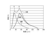
次に、図15から図19を参照して、実施の形態3にかかる非線形抵抗樹脂材料1Dについて説明する。図15は、実施の形態3にかかる非線形抵抗樹脂材料1Dを模式的に示した図である。図16は、実施の形態3にかかる非線形抵抗樹脂材料1Dの第1の粒子2の粒度分布を示した図である。図17は、実施の形態3にかかる非線形抵抗樹脂材料1Dの第1の粒子2の混合割合と充填率との関係を示した図である。図18は、実施の形態3にかかる非線形抵抗樹脂材料1Dの通電経路Zを示した図である。図19は、実施の形態3にかかる非線形抵抗樹脂材料1Dの第1の粒子2の電流-電圧特性と、実施の形態1にかかる非線形抵抗樹脂材料1の第1の粒子2の電流-電圧特性とを示した図である。実施の形態3にかかる非線形抵抗樹脂材料1Dは、粒度分布が異なる2種類の第1の粒子2を備える点が前記した実施の形態1の変形例2にかかる非線形抵抗樹脂材料1Bと相違する。実施の形態3では、前記した実施の形態1の変形例2にかかる非線形抵抗樹脂材料1Bと重複する部分については、同一符号を付して説明を省略する。
Next, the nonlinear
図15に示される非線形抵抗樹脂材料1Dは、粒度分布が異なる2種類以上の第1の粒子2を備えている。非線形抵抗樹脂材料1Dは、平均粒径が異なる2種類以上の第1の粒子2を備えている。本実施の形態では、平均粒径が50μmの第1の粒子2と平均粒径が20μmの第1の粒子2とを混合した場合であって、かつ、平均粒径が50μmの第1の粒子2の粒度分布と平均粒径が20μmの第1の粒子2の粒度分布とが異なる場合を例示する。以下、平均粒径が50μmの第1の粒子2を大粒子8と称し、平均粒径が20μmの第1の粒子2を小粒子9と称する場合もある。図15では、大粒子8と小粒子9とを区別するために、大粒子8を白抜きで図示し、小粒子9にハッチングを付している。小粒子9は、大粒子8同士の間の空隙4に入り込んでいる。小粒子9は、大粒子8同士の間の空隙4を埋めるように配置されている。なお、第1の粒子2の平均粒径は、例示した数値に限定されない。
The nonlinear
図16のA線は、平均粒径が50μmの第1の粒子2の粒度分布を示している。図16のB線は、平均粒径が20μmの第1の粒子2の粒度分布を示している。図16のC線は、第1の粒子2全体の粒度分布を示している。図16の横軸は第1の粒子2の粒径(μm)であり、図16の縦軸は各粒径の第1の粒子2が占める割合(%)である。平均粒径が50μmの第1の粒子2の粒度分布と平均粒径が20μmの第1の粒子2の粒度分布とは、互いに異なっている。第1の粒子2全体の粒度分布は、第1の粒子2が存在する割合が極大となる2つの極大値Pを有している。換言すると、第1の粒子2全体の粒度分布を、横軸を所定の粒径で区分し、縦軸を各粒径の第1の粒子2が占める割合とする粒度分布曲線で示す場合において、粒度分布曲線は、2つの極大値Pを有する形状である。Line A in FIG. 16 shows the particle size distribution of
図17には、平均粒径が50μmの第1の粒子2の混合割合(vol%)と第1の粒子2の充填率(vol%)との関係を示している。図17の横軸は平均粒径が50μmの第1の粒子2の混合割合(vol%)であり、図17の縦軸は第1の粒子2の充填率(vol%)である。第1の粒子2の充填率とは、非線形抵抗樹脂材料1Dに占める第1の粒子2の体積割合のことを意味する。図17から明らかなように、平均粒径が50μmの第1の粒子2の混合割合が60vol%において、第1の粒子2の充填率が極大となった。なお、平均粒径が50μmの第1の粒子2の混合割合が60vol%の場合には、平均粒径が20μmの第1の粒子2の混合割合は40vol%となる。
Figure 17 shows the relationship between the mixing ratio (vol%) of the
次に、本実施の形態にかかる非線形抵抗樹脂材料1Dの効果について説明する。Next, the effects of the nonlinear
図8に示される実施の形態1の変形例2のように、平均粒径が50μmの第1の粒子2のみを使用する場合、すなわち粒度分布が1種類の第1の粒子2を使用する場合には、隣り合う第1の粒子2同士の間の空隙4が大きくなる。これに対して、図15に示される本実施の形態のように、非線形抵抗樹脂材料1Dは粒度分布が異なる2種類の第1の粒子2を備え、第1の粒子2全体の粒度分布は第1の粒子2が存在する割合が極大となる2つの極大値Pを有していると、粒径が大きな大粒子8同士の間の空隙4に粒径が小さな小粒子9が入り込む。そのため、隣り合う第1の粒子2同士の間の空隙4が小さくなるか、または、無くなるため、第1の粒子2の充填率を高められる。そして、粒径が大きな大粒子8同士の間に粒径が小さな小粒子9が入り込むことにより、第1の粒子2同士の結着面積を増やすことができる。その結果、図18に示すように、第1の粒子2同士を電気的に接続する通電経路Zが増える。すなわち、通電は第1の粒子2の結着部分を介して行われるため、第1の粒子2同士の結着面積を増やすことで、第1の粒子2同士を電気的に接続する通電経路Zを増やすことができる。通電経路Zが増えると、閾値電圧Vthを超えた後の電流領域において、多くの電流を流すことができる。
As in the second modification of the first embodiment shown in FIG. 8, when only the
図19の線L1´は、平均粒径が50μmの第1の粒子2の混合割合が60vol%かつ平均粒径が20μmの第1の粒子2の混合割合が40vol%の場合、すなわち第1の粒子2の充填率が極大となる場合における非線形抵抗樹脂材料1Dの第1の粒子2の電流-電圧特性を示している。図19の線L1は、図5に示されるL1と同一であり、実施の形態1にかかる非線形抵抗樹脂材料1の第1の粒子2の電流-電圧特性を示している。図19から明らかなように、線L1´の傾きは、線L1の傾きよりも小さい。換言すると、本実施の形態では、線L1の傾きをさらに小さくして線L1´にできる。そのため、本実施の形態では、前記した実施の形態1に比べて、非線形抵抗樹脂材料1Dの非線形抵抗特性をさらに向上させて、非線形抵抗樹脂材料1Dの非線形抵抗指数をさらに大きくすることができる。
Line L1' in FIG. 19 shows the current-voltage characteristics of the
図20は、実施の形態3の変形例にかかる非線形抵抗樹脂材料1Eを模式的に示した図である。図20に示すように、非線形抵抗樹脂材料1Eは、第1の粒子2および第1の樹脂相3以外の部分に形成される空隙4を埋めるとともに絶縁性を有する第2の樹脂相5を備えていてもよい。
Figure 20 is a schematic diagram of a nonlinear
非線形抵抗樹脂材料1Dは、本実施の形態では粒度分布が異なる2種類の第1の粒子2を備えたが、第1の粒子2の充填率を高められるようであれば、粒度分布が異なる3種類以上の第1の粒子2を備えていてもよい。換言すると、非線形抵抗樹脂材料1Dは、粒度分布が異なる2種類以上の第1の粒子2を備えていてもよい。なお、第1の粒子2全体の粒度分布は、第1の粒子2が存在する割合が極大となる2つ以上の極大値Pを有していてもよい。In this embodiment, the nonlinear
平均粒径が50μmの第1の粒子2が第2の粒子32を含んだ第1の樹脂相3により覆われて、平均粒径が20μmの第1の粒子2が第1の樹脂相3により覆われていなくてもよい。このようにしても、図19に示される線L1から線L1´に向かうように第1の粒子2の電流-電圧特性が向上することが本開示者の実験および研究により確認されている。なお、第1の粒子2同士の結着が不十分であった場合には、図20に示されるように平均粒径が20μmの第1の粒子2が第2の粒子32を含まない第3の樹脂相10により覆われてもよい。第3の樹脂相10の組成は、第2の粒子32を含まない点以外は、第1の樹脂相3の組成と同一でもよい。一方、平均粒径が50μmの第1の粒子2が第1の樹脂相3により覆われず、平均粒径が20μmの第1の粒子2が第2の粒子32を含んだ第1の樹脂相3により覆われていてもよい。このようにしても、図19に示される線L1から線L1´に向かうように第1の粒子2の電流-電圧特性が向上することが本開示者の実験および研究により確認されている。なお、第1の粒子2同士の結着が不十分であった場合には、平均粒径が50μmの第1の粒子2が第2の粒子32を含まない第3の樹脂相10により覆われてもよい。以上のとおり、非線形抵抗樹脂材料1Dが、平均粒径が異なる2種類の第1の粒子2を備える場合には、少なくとも1種類の第1の粒子2は第2の粒子32を含んだ第1の樹脂相3により覆われて、少なくとも1種類の第1の粒子2は第1の樹脂相3により覆われていないか、または、第2の粒子32を含まない第3の樹脂相10により覆われていてもよい。このようにすると、第2の粒子32を含んだ第1の樹脂相3の使用量を減らせたり、第2の粒子32を含んだ第1の樹脂相3の処理量を減らせたりするため、非線形抵抗樹脂材料1Dの生産性の向上を図ることができる。また、少なくとも1種類の第1の粒子2が第1の樹脂相3により覆われていない場合には、混合工程において、少なくとも1種類の第1の粒子2と液体状態の第1のマトリックス樹脂31と第2の粒子32とを混合して成形前の非線形抵抗樹脂材料1Dを作製した後に、この成形前の非線形抵抗樹脂材料1Dに平均粒径が異なる他の種類の第1の粒子2を混合すればよい。また、少なくとも1種類の第1の粒子2が第3の樹脂相10により覆われている場合には、混合工程において、少なくとも1種類の第1の粒子2と液体状態の第1のマトリックス樹脂31と第2の粒子32とを混合して成形前の非線形抵抗樹脂材料1Dを作製する工程と、平均粒径が異なる他の種類の第1の粒子2と、第3の樹脂相10となる液体状態のマトリックス樹脂とを混合して成形前の非線形抵抗樹脂材料1Dを作製する工程とを別々に行えばよい。そして、別々に作製した成形前の非線形抵抗樹脂材料1Dを混合すればよい。
The
非線形抵抗樹脂材料1Dが、平均粒径が異なる3種類以上の第1の粒子2を備える場合には、少なくとも1種類の第1の粒子2は第2の粒子32を含んだ第1の樹脂相3により覆われて、少なくとも1種類の第1の粒子2は第1の樹脂相3により覆われていないか、または、第2の粒子32を含まない第3の樹脂相10により覆われていてもよい。このようにしても、図19に示される線L1から線L1´に向かうように第1の粒子2の電流-電圧特性が向上することが本開示者の実験および研究により確認されている。また、第2の粒子32を含んだ第1の樹脂相3の使用量を減らせたり、第2の粒子32を含んだ第1の樹脂相3の処理量を減らせたりするため、非線形抵抗樹脂材料1Dの生産性の向上を図ることができる。
When the nonlinear
非線形抵抗樹脂材料1Dが、平均粒径が1種類の第1の粒子2を備える場合には、少なくとも一部の第1の粒子2は第2の粒子32を含んだ第1の樹脂相3により覆われて、少なくとも一部の第1の粒子2は第1の樹脂相3により覆われていないか、または、第2の粒子32を含まない第3の樹脂相10により覆われていてもよい。このようにしても、図19に示される線L1から線L1´に向かうように第1の粒子2の電流-電圧特性が向上することが本開示者の実験および研究により確認されている。また、第2の粒子32を含んだ第1の樹脂相3の使用量を減らせたり、第2の粒子32を含んだ第1の樹脂相3の処理量を減らせたりするため、非線形抵抗樹脂材料1Dの生産性の向上を図ることができる。When the nonlinear
次に、実施例および比較例により、本開示の効果について更に説明する。Next, the effects of the present disclosure will be further explained using examples and comparative examples.
(材料組成)
表1に示す配合量に従って、成形圧力を加えた実施例1~41にかかる非線形抵抗樹脂材料および成形圧力を加えなかった比較例1~8にかかる非線形抵抗樹脂材料を作製した。第1の樹脂相を構成する第1のマトリックス樹脂には、ポリビニルアルコール樹脂(三菱ケミカル株式会社製「GL-05」)を使用した。第1の樹脂相を構成する第2の粒子には、カーボン粉末(株式会社高純度化学研究所製「CCE03PB」)を使用した。第2の樹脂相には、エポキシ樹脂(主剤:ナガセケムテックス株式会社製「CY230」、硬化剤:ナガセケムテックス株式会社製「HY951」)を使用した。実施例1~41では、成形前の非線形抵抗樹脂材料を金型内に充填し、非線形抵抗樹脂材料に300kgf/cm2の成形圧力を加えて非線形抵抗樹脂材料を成形した。非線形抵抗樹脂材料を加圧することによって、第1の粒子同士が結着されるとともに電気的に接続される状態となる。非線形抵抗樹脂材料に成形圧力を加えなかった比較例1~8では、第1の粒子同士が結着しておらず電気的に接続されていない状態となる。実施例1~41にかかる非線形抵抗樹脂材料および比較例1~8にかかる非線形抵抗樹脂材料では、非線形抵抗特性を有する第1の粒子同士の電気的な接続、加圧、非線形抵抗樹脂材料に占める第1の粒子の体積割合、非線形抵抗樹脂材料に占める第1の樹脂相のマトリックス樹脂の体積割合、非線形抵抗樹脂材料に占める第1の樹脂相の第2の粒子の体積割合、非線形抵抗樹脂材料に占める空隙または第2の樹脂相の体積割合、第1の樹脂相に占める第2の粒子の体積割合、第1の粒子に対する第2の粒子の平均粒径を変えている。
(Material Composition)
According to the compounding amounts shown in Table 1, the nonlinear resistance resin materials according to Examples 1 to 41 in which molding pressure was applied and the nonlinear resistance resin materials according to Comparative Examples 1 to 8 in which molding pressure was not applied were prepared. A polyvinyl alcohol resin ("GL-05" manufactured by Mitsubishi Chemical Corporation) was used as the first matrix resin constituting the first resin phase. A carbon powder ("CCE03PB" manufactured by Kojundo Chemical Laboratory Co., Ltd.) was used as the second particles constituting the first resin phase. An epoxy resin (main agent: "CY230" manufactured by Nagase ChemteX Corporation, hardener: "HY951" manufactured by Nagase ChemteX Corporation) was used as the second resin phase. In Examples 1 to 41, the nonlinear resistance resin material before molding was filled in a mold, and a molding pressure of 300 kgf/cm 2 was applied to the nonlinear resistance resin material to mold the nonlinear resistance resin material. By applying pressure to the nonlinear resistance resin material, the first particles are bonded to each other and are electrically connected. In Comparative Examples 1 to 8, in which no molding pressure was applied to the nonlinear resistance resin material, the first particles are not bonded together and are not electrically connected. In the nonlinear resistance resin materials according to Examples 1 to 41 and the nonlinear resistance resin materials according to Comparative Examples 1 to 8, the electrical connection between the first particles having nonlinear resistance characteristics, the pressure, the volume ratio of the first particles in the nonlinear resistance resin material, the volume ratio of the matrix resin of the first resin phase in the nonlinear resistance resin material, the volume ratio of the second particles in the first resin phase in the nonlinear resistance resin material, the volume ratio of the voids or the second resin phase in the nonlinear resistance resin material, the volume ratio of the second particles in the first resin phase, and the average particle size of the second particles relative to the first particles are changed.

(試験方法)
実施例1~41および比較例1~8にかかる非線形抵抗樹脂材料について、以下に示した試験方法により非線形抵抗特性、強度、放電開始電界をそれぞれ測定し、非線形抵抗特性、強度、放電開始電界の評価を行った。各評価は、5段階で記した。数が大きいほど良く、数が小さいほど悪いことを示し、3以上が許容範囲であることを示す。非線形抵抗特性は、非線形抵抗指数で表した。
(Test Method)
For the nonlinear resistance resin materials of Examples 1 to 41 and Comparative Examples 1 to 8, the nonlinear resistance characteristics, strength, and discharge start electric field were measured by the test methods shown below, and the nonlinear resistance characteristics, strength, and discharge start electric field were evaluated. Each evaluation was recorded on a 5-point scale. The higher the number, the better, and the lower the number, the worse, with 3 or more indicating an acceptable range. The nonlinear resistance characteristics were expressed as a nonlinear resistance index.
[非線形抵抗指数]
得られた非線形抵抗樹脂材料に対して、電圧を印加しながら、通電電流の値を測定して電流-電圧特性を取得し、非線形抵抗指数を算出した。
[Nonlinear Resistance Index]
A voltage was applied to the obtained nonlinear resistance resin material, while the value of the current passing through the material was measured to obtain the current-voltage characteristics, and the nonlinear resistance index was calculated.
[強度]
得られた非線形抵抗樹脂材料に対して、圧縮を行い、圧縮強度を測定した。
[Strength]
The obtained nonlinear resistance resin material was compressed to measure the compressive strength.
[放電開始電界]
得られた非線形抵抗樹脂材料に対して、電圧を印加して、放電が発生するときの電圧値を測定した。
[Discharge starting electric field]
A voltage was applied to the obtained nonlinear resistance resin material, and the voltage value at which a discharge occurred was measured.
表1から明らかなように、非線形抵抗樹脂材料に成形圧力を加えた実施例1~41では、非線形抵抗特性を有する第1の粒子同士が結着して電気的に接続されているため、非線形抵抗指数が3以上であり、非線形抵抗特性を示した。一方で、非線形抵抗樹脂材料に成形圧力を加えなかった比較例1~8では、非線形抵抗特性を有する第1の粒子同士が結着しておらず電気的に接続されていないため、非線形抵抗指数が1または2であり、非線形抵抗特性を示さなかった。このことから、非線形抵抗樹脂材料に成形圧力を加えることによって、非線形抵抗特性を有する第1の粒子同士が結着して電気的に接続されていることが、非線形抵抗特性の向上に有効であることが分かった。As is clear from Table 1, in Examples 1 to 41 in which molding pressure was applied to the nonlinear resistance resin material, the first particles having nonlinear resistance characteristics were bonded together and electrically connected, so the nonlinear resistance index was 3 or more, and nonlinear resistance characteristics were exhibited. On the other hand, in Comparative Examples 1 to 8 in which molding pressure was not applied to the nonlinear resistance resin material, the first particles having nonlinear resistance characteristics were not bonded together and electrically connected, so the nonlinear resistance index was 1 or 2, and nonlinear resistance characteristics were not exhibited. From this, it was found that applying molding pressure to the nonlinear resistance resin material, which causes the first particles having nonlinear resistance characteristics to be bonded together and electrically connected, is effective in improving the nonlinear resistance characteristics.
非線形抵抗樹脂材料に占める第1の粒子の体積割合が25vol%以上74vol%以下、かつ、第1の樹脂相に占める第2の粒子の体積割合が1vol%以上40vol%以下である実施例1、実施例2、実施例3、実施例4、実施例7、実施例8、実施例9、実施例10、実施例12、実施例13、実施例14、実施例15、実施例16、実施例17、実施例18、実施例19、実施例20、実施例21、実施例22、実施例23、実施例24、実施例25、実施例26、実施例27、実施例36、実施例38、実施例39、実施例40、実施例41では、非線形抵抗指数が4以上であった。一方で、非線形抵抗樹脂材料に占める第1の粒子の体積割合が25vol%以上74vol%以下ではない、または、第1の樹脂相に占める第2の粒子の体積割合が1vol%以上40vol%以下ではない実施例5、実施例6、実施例11、実施例28、実施例29、実施例30、実施例31、実施例32、実施例33、実施例34、実施例35では、非線形抵抗指数が3であった。このことから、非線形抵抗樹脂材料に占める第1の粒子の体積割合が25vol%以上74vol%以下、かつ、第1の樹脂相に占める第2の粒子の体積割合が1vol%以上40vol%以下であることが、非線形抵抗特性の向上に有効であることが分かった。In Examples 1, 2, 3, 4, 7, 8, 9, 10, 12, 13, 14, 15, 16, 17, 18, 19, 20, 21, 22, 23, 24, 25, 26, 27, 36, 38, 39, 40, and 41, in which the volume fraction of the first particles in the nonlinear resistance resin material was 25 vol% or more and 74 vol% or less and the volume fraction of the second particles in the first resin phase was 1 vol% or more and 40 vol% or less, the nonlinear resistance index was 4 or more. On the other hand, in Examples 5, 6, 11, 28, 29, 30, 31, 32, 33, 34, and 35 in which the volume ratio of the first particles in the nonlinear resistance resin material was not 25 vol% or more and 74 vol% or less, or the volume ratio of the second particles in the first resin phase was not 1 vol% or more and 40 vol% or less, the nonlinear resistance index was 3. From this, it was found that the volume ratio of the first particles in the nonlinear resistance resin material was 25 vol% or more and 74 vol% or less, and the volume ratio of the second particles in the first resin phase was 1 vol% or more and 40 vol% or less, which is effective in improving the nonlinear resistance characteristics.
非線形抵抗指数が4以上の実施例の中で、非線形抵抗樹脂材料に占める第2の粒子の体積割合が0.2vol%以上2vol%以下、かつ、空隙または第2の樹脂相の体積が第1の樹脂相の体積よりも大きい実施例1、実施例2、実施例3、実施例8、実施例9、実施例10、実施例17、実施例18、実施例19、実施例25、実施例26、実施例27、実施例38、実施例39、実施例40では、非線形抵抗指数が5であった。このことから、非線形抵抗樹脂材料に占める第2の粒子の体積割合が0.2vol%以上2vol%以下、かつ、空隙または第2の樹脂相の体積が第1の樹脂相の体積よりも大きいことが、非線形抵抗特性の向上に有効であることが分かった。Among the examples with a nonlinear resistance index of 4 or more, in Examples 1, 2, 3, 8, 9, 10, 17, 18, 19, 25, 26, 27, 38, 39, and 40 in which the volume fraction of the second particles in the nonlinear resistance resin material is 0.2 vol% or more and 2 vol% or less, and the volume of the voids or the second resin phase is larger than the volume of the first resin phase, the nonlinear resistance index was 5. From this, it was found that the volume fraction of the second particles in the nonlinear resistance resin material is 0.2 vol% or more and 2 vol% or less, and the volume of the voids or the second resin phase is larger than the volume of the first resin phase, is effective in improving the nonlinear resistance characteristics.
実施例1と実施例36とは、第1の粒子に対する第2の粒子の平均粒径の違いである。同様に、実施例7と実施例37とは、第1の粒子に対する第2の粒子の平均粒径の違いである。第2の粒子の平均粒径が第1の粒子の平均粒径の1/10以下である実施例1では非線形抵抗指数が5であったのに対して、第2の粒子の平均粒径が第1の粒子の平均粒径の1/10を超える実施例36では非線形抵抗指数が4であった。また、第2の粒子の平均粒径が第1の粒子の平均粒径の1/10以下である実施例7では非線形抵抗指数が4であったのに対して、第2の粒子の平均粒径が第1の粒子の平均粒径の1/10を超える実施例37では非線形抵抗指数が3であった。このことから、第2の粒子の平均粒径が第1の粒子の平均粒径の1/10以下であることが、非線形抵抗特性の向上に有効であることが分かった。 Example 1 and Example 36 are different in the average particle size of the second particles relative to the first particles. Similarly, Example 7 and Example 37 are different in the average particle size of the second particles relative to the first particles. In Example 1, where the average particle size of the second particles is 1/10 or less of the average particle size of the first particles, the nonlinear resistance index was 5, whereas in Example 36, where the average particle size of the second particles exceeds 1/10 of the average particle size of the first particles, the nonlinear resistance index was 4. In addition, in Example 7, where the average particle size of the second particles is 1/10 or less of the average particle size of the first particles, the nonlinear resistance index was 4, whereas in Example 37, where the average particle size of the second particles exceeds 1/10 of the average particle size of the first particles, the nonlinear resistance index was 3. From this, it was found that the average particle size of the second particles being 1/10 or less of the average particle size of the first particles is effective in improving the nonlinear resistance characteristics.
実施例1と実施例40とは、第2の樹脂相で空隙を埋めた状態であるか空隙を埋めていない状態であるかの違いである。同様に、実施例7と実施例41とは、第2の樹脂相で空隙を埋めた状態であるか空隙を埋めていない状態であるかの違いである。第2の樹脂相で空隙を埋めていない状態である実施例1では、強度および放電開始電界が3であったのに対して、第2の樹脂相で空隙を埋めた状態である実施例40では強度および放電開始電界が5であった。また、第2の樹脂相で空隙を埋めていない状態である実施例7では強度および放電開始電界が4であったのに対して、第2の樹脂相で空隙を埋めた状態である実施例41では、強度および放電開始電界が5であった。このことから、第2の樹脂相で空隙を埋めることが、強度および放電特性の向上に有効であることが分かった。 The difference between Example 1 and Example 40 is whether the voids are filled with the second resin phase or not. Similarly, the difference between Example 7 and Example 41 is whether the voids are filled with the second resin phase or not. In Example 1, in which the voids are not filled with the second resin phase, the strength and discharge start electric field were 3, whereas in Example 40, in which the voids are filled with the second resin phase, the strength and discharge start electric field were 5. In addition, in Example 7, in which the voids are not filled with the second resin phase, the strength and discharge start electric field were 4, whereas in Example 41, in which the voids are filled with the second resin phase, the strength and discharge start electric field were 5. From this, it was found that filling the voids with the second resin phase is effective in improving the strength and discharge characteristics.
実施例40と比較例7との相違、および、実施例41と比較例8との相違は、第2の樹脂相を備えた状態での加圧の有無のみである。実施例40,41および比較例7,8のいずれも第2の樹脂相を備えることで強度および放電開始電界を高い水準に保つことができるが、非線形抵抗樹脂材料に成形圧力を加えなかった比較例7,8においては、第1の粒子同士が結着しておらず電気的に接続されていないため、実施例40,41に比べて非線形抵抗指数が小さい値となった。The only difference between Example 40 and Comparative Example 7, and between Example 41 and Comparative Example 8, is the presence or absence of pressure when the second resin phase is provided. In both Examples 40 and 41 and Comparative Examples 7 and 8, the strength and discharge initiation electric field can be maintained at a high level by providing a second resin phase, but in Comparative Examples 7 and 8, where molding pressure was not applied to the nonlinear resistance resin material, the first particles were not bonded together and were not electrically connected, resulting in a smaller nonlinear resistance index than in Examples 40 and 41.
以上の実施の形態に示した構成は、一例を示すものであり、別の公知の技術と組み合わせることも可能であるし、実施の形態同士を組み合わせることも可能であるし、要旨を逸脱しない範囲で、構成の一部を省略、変更することも可能である。 The configurations shown in the above embodiments are merely examples, and may be combined with other known technologies, or the embodiments may be combined with each other. Also, parts of the configurations may be omitted or modified without departing from the spirit of the invention.
1,1A,1B,1C,1D,1E 非線形抵抗樹脂材料、2 第1の粒子、3 第1の樹脂相、4 空隙、5 第2の樹脂相、6 過電圧保護装置、7 被保護機器、8 大粒子、9 小粒子、10 第3の樹脂相、21 接触部、22 非接触部、31 第1のマトリックス樹脂、32 第2の粒子、61 非線形抵抗体、62,62a,62b 電極、63 配線。 1, 1A, 1B, 1C, 1D, 1E nonlinear resistance resin material, 2 first particle, 3 first resin phase, 4 void, 5 second resin phase, 6 overvoltage protection device, 7 protected device, 8 large particle, 9 small particle, 10 third resin phase, 21 contact portion, 22 non-contact portion, 31 first matrix resin, 32 second particle, 61 nonlinear resistor, 62, 62a, 62b electrodes, 63 wiring.
Claims (13)
半導電性または導電性の第2の粒子を含み、複数の前記第1の粒子のうちの一部または全部の表面の少なくとも一部を覆う第1の樹脂相と、
前記第1の粒子および前記第1の樹脂相以外の部分に形成される空隙を埋めるとともに絶縁性を有する第2の樹脂相と、を備え、
隣り合う前記第1の粒子同士は、前記第1の樹脂相を介して互いに結着されるとともに電気的に接続されていることを特徴とする非線形抵抗樹脂材料。 A plurality of first particles having nonlinear resistance characteristics that exhibit insulating properties when a voltage less than a threshold is applied and that exhibit conductive properties when a voltage equal to or greater than the threshold is applied;
A first resin phase including semiconductive or conductive second particles and covering at least a portion of a surface of some or all of the first particles;
a second resin phase that fills voids formed in a portion other than the first particles and the first resin phase and has insulating properties;
A nonlinear resistance resin material, characterized in that adjacent first particles are bound to each other and electrically connected via the first resin phase.
前記第1の樹脂相に占める前記第2の粒子の体積割合は、1vol%以上40vol%以下であることを特徴とする請求項1に記載の非線形抵抗樹脂材料。 a volume ratio of the first particles to the nonlinear resistance resin material is 25 vol% or more and 74 vol% or less,
2. The nonlinear resistance resin material according to claim 1, wherein a volume ratio of the second particles to the first resin phase is 1 vol % or more and 40 vol % or less.
前記非線形抵抗樹脂材料に占める前記第2の樹脂相の体積割合は、前記非線形抵抗樹脂材料に占める前記第1の樹脂相の体積割合よりも大きいことを特徴とする請求項2に記載の非線形抵抗樹脂材料。 a volume ratio of the second particles in the nonlinear resistance resin material is 0.2 vol % or more and 2 vol % or less,
3. The nonlinear resistance resin material according to claim 2, wherein a volume ratio of the second resin phase in the nonlinear resistance resin material is greater than a volume ratio of the first resin phase in the nonlinear resistance resin material.
前記第1の粒子全体の粒度分布は、前記第1の粒子が存在する割合が極大となる2つ以上の極大値を有していることを特徴とする請求項4に記載の非線形抵抗樹脂材料。 Two or more types of the first particles having different particle size distributions are provided,
5. The nonlinear resistance resin material according to claim 4, wherein the particle size distribution of the entire first particles has two or more maximum values at which the proportion of the first particles present is maximized.
少なくとも1種類の前記第1の粒子は、前記第2の粒子を含んだ前記第1の樹脂相により覆われていることを特徴とする請求項5に記載の非線形抵抗樹脂材料。 Two or more types of the first particles having different average particle sizes are provided,
6. The nonlinear resistance resin material according to claim 5, wherein at least one type of the first particles is covered with the first resin phase containing the second particles.
前記非線形抵抗樹脂材料に取り付けられた複数の電極と、を備えることを特徴とする非線形抵抗体。 The nonlinear resistance resin material according to any one of claims 1 to 10,
and a plurality of electrodes attached to the nonlinear resistive resin material.
請求項11に記載の非線形抵抗体と、
前記被保護機器に電気的に接続された配線と、を備え、
複数の前記電極のうち少なくとも1つは接地され、複数の前記電極のうち少なくとも1つは前記配線に接続されていることを特徴とする過電圧保護装置。 An overvoltage protection device that prevents an overvoltage from being applied to a protected device,
A nonlinear resistor according to claim 11;
a wiring electrically connected to the protected device;
At least one of the plurality of electrodes is grounded, and at least one of the plurality of electrodes is connected to the wiring.
前記第1の樹脂相で覆われた前記第1の粒子を備える非線形抵抗樹脂材料を所定の形状に成形する加圧成形工程と、
成形された前記非線形抵抗樹脂材料に、絶縁性を有する第2の樹脂相を複合化する複合化工程と、
を含むことを特徴とする非線形抵抗樹脂材料の製造方法。 a mixing step of mixing a plurality of first particles having nonlinear resistance characteristics that show insulation when a voltage below a threshold is applied and show conductivity when a voltage equal to or higher than a threshold is applied with a first resin phase containing semiconductive or conductive second particles, and covering at least a portion of a surface of some or all of the plurality of first particles with the first resin phase;
a pressure molding step of molding the nonlinear resistance resin material having the first particles covered with the first resin phase into a predetermined shape;
a compounding step of compounding the molded nonlinear resistance resin material with a second resin phase having insulating properties;
A method for producing a nonlinear resistance resin material, comprising:
Applications Claiming Priority (3)
| Application Number | Priority Date | Filing Date | Title |
|---|---|---|---|
| JPPCT/JP2022/002377 | 2022-01-24 | ||
| JP2022002377 | 2022-01-24 | ||
| PCT/JP2022/047193 WO2023140034A1 (en) | 2022-01-24 | 2022-12-21 | Nonlinear resistive resin material, non-linear resistive body, overvoltage protection device, and method for manufacturing nonlinear resistive resin material |
Publications (3)
| Publication Number | Publication Date |
|---|---|
| JPWO2023140034A1 JPWO2023140034A1 (en) | 2023-07-27 |
| JPWO2023140034A5 JPWO2023140034A5 (en) | 2024-04-02 |
| JP7657331B2 true JP7657331B2 (en) | 2025-04-04 |
Family
ID=87348203
Family Applications (1)
| Application Number | Title | Priority Date | Filing Date |
|---|---|---|---|
| JP2023575151A Active JP7657331B2 (en) | 2022-01-24 | 2022-12-21 | Nonlinear resistance resin material, nonlinear resistor, overvoltage protection device, and method for producing nonlinear resistance resin material |
Country Status (4)
| Country | Link |
|---|---|
| US (1) | US20250104892A1 (en) |
| EP (1) | EP4471097A4 (en) |
| JP (1) | JP7657331B2 (en) |
| WO (1) | WO2023140034A1 (en) |
Citations (2)
| Publication number | Priority date | Publication date | Assignee | Title |
|---|---|---|---|---|
| JP2002506578A (en) | 1998-04-27 | 2002-02-26 | エー ビー ビー リサーチ リミテッド | Nonlinear resistor having varistor characteristics and method of manufacturing the resistor |
| JP2016134605A (en) | 2015-01-22 | 2016-07-25 | 株式会社東芝 | Composite resin and electronic device |
Family Cites Families (9)
| Publication number | Priority date | Publication date | Assignee | Title |
|---|---|---|---|---|
| US6232866B1 (en) * | 1995-09-20 | 2001-05-15 | The United States Of America As Represented By The Administrator Of The National Aeronautics And Space Administration | Composite material switches |
| ATE403935T1 (en) * | 2004-04-06 | 2008-08-15 | Abb Research Ltd | ELECTRICAL NONLINEAR MATERIAL FOR HIGH AND MEDIUM VOLTAGE APPLICATIONS |
| US9082622B2 (en) * | 2010-02-26 | 2015-07-14 | Littelfuse, Inc. | Circuit elements comprising ferroic materials |
| JP6009839B2 (en) * | 2012-07-03 | 2016-10-19 | 株式会社東芝 | Non-linear resistance material |
| JP6119005B2 (en) * | 2013-09-26 | 2017-04-26 | 音羽電機工業株式会社 | Non-ohmic resin material, method for producing the same, and non-ohmic resistor using the resin material |
| JP2015101714A (en) | 2013-11-28 | 2015-06-04 | 株式会社東芝 | Nonlinear resistance resin material |
| TWI508258B (en) * | 2013-12-19 | 2015-11-11 | 矽品精密工業股份有限公司 | Semiconductor package and its manufacturing method |
| JP6657710B2 (en) * | 2015-09-28 | 2020-03-04 | 住友ベークライト株式会社 | Thermosetting resin sheet and method for manufacturing semiconductor device |
| US12206234B2 (en) * | 2022-09-20 | 2025-01-21 | Ripd Ip Development Ltd | Overvoltage protection device modules |
-
2022
- 2022-12-21 WO PCT/JP2022/047193 patent/WO2023140034A1/en not_active Ceased
- 2022-12-21 JP JP2023575151A patent/JP7657331B2/en active Active
- 2022-12-21 EP EP22922184.1A patent/EP4471097A4/en not_active Withdrawn
- 2022-12-21 US US18/730,305 patent/US20250104892A1/en active Pending
Patent Citations (2)
| Publication number | Priority date | Publication date | Assignee | Title |
|---|---|---|---|---|
| JP2002506578A (en) | 1998-04-27 | 2002-02-26 | エー ビー ビー リサーチ リミテッド | Nonlinear resistor having varistor characteristics and method of manufacturing the resistor |
| JP2016134605A (en) | 2015-01-22 | 2016-07-25 | 株式会社東芝 | Composite resin and electronic device |
Also Published As
| Publication number | Publication date |
|---|---|
| WO2023140034A1 (en) | 2023-07-27 |
| EP4471097A4 (en) | 2025-08-27 |
| JPWO2023140034A1 (en) | 2023-07-27 |
| US20250104892A1 (en) | 2025-03-27 |
| EP4471097A1 (en) | 2024-12-04 |
Similar Documents
| Publication | Publication Date | Title |
|---|---|---|
| CN1681052B (en) | Nonlinear Electrical Materials for Medium and High Voltage Applications | |
| US4103274A (en) | Reconstituted metal oxide varistor | |
| JP4921623B2 (en) | Nonlinear resistance having varistor characteristics and method of manufacturing the resistance | |
| JP2934884B2 (en) | Composition for electrical overstress and pulse protection | |
| CN105321639B (en) | overcurrent protection element | |
| JP4190595B2 (en) | Electrical and thermal conductive laminate | |
| EP0533760B1 (en) | Method of manufacturing an electrical device | |
| CN105390219A (en) | Component with over-voltage over-current protective effect and manufacturing process of the same | |
| JP6119005B2 (en) | Non-ohmic resin material, method for producing the same, and non-ohmic resistor using the resin material | |
| US9424967B2 (en) | Voltage-limiting composition | |
| JP7657331B2 (en) | Nonlinear resistance resin material, nonlinear resistor, overvoltage protection device, and method for producing nonlinear resistance resin material | |
| Tao et al. | Novel isotropical conductive adhesives for electronic packaging application | |
| CN1655290A (en) | Macromolecular positive temperature coefficient thermosensitive resistor and method for making same | |
| CN114464345B (en) | Conductive silver paste, preparation method and composite structure | |
| JPH11506870A (en) | Electrical device with PTC behavior | |
| ITMI20002695A1 (en) | CONDUCTIVE POLYMER COMPOSITIONS CONTAINING FIBER FIBERS AND DEVICES | |
| TW200834612A (en) | Polymeric positive temperature coefficient thermistor and process for preparing the same | |
| US20210354332A1 (en) | Compositions for bipolar plates and methods for manufacturing said compositions | |
| CN212782901U (en) | High reliability overcurrent protection components | |
| US20240105364A1 (en) | Vacuum valve and method for manufacturing same | |
| JP6457743B2 (en) | Connection structure | |
| US7304562B2 (en) | Organic PTC thermistor and production | |
| JP2010165544A (en) | Conductive resin material | |
| CN1318201A (en) | PTC device and method for producing same | |
| CA1096051A (en) | Reconstituted metal oxide varistor |
Legal Events
| Date | Code | Title | Description |
|---|---|---|---|
| A521 | Request for written amendment filed |
Free format text: JAPANESE INTERMEDIATE CODE: A523 Effective date: 20231228 |
|
| A621 | Written request for application examination |
Free format text: JAPANESE INTERMEDIATE CODE: A621 Effective date: 20231228 |
|
| TRDD | Decision of grant or rejection written | ||
| A01 | Written decision to grant a patent or to grant a registration (utility model) |
Free format text: JAPANESE INTERMEDIATE CODE: A01 Effective date: 20250225 |
|
| A61 | First payment of annual fees (during grant procedure) |
Free format text: JAPANESE INTERMEDIATE CODE: A61 Effective date: 20250325 |
|
| R150 | Certificate of patent or registration of utility model |
Ref document number: 7657331 Country of ref document: JP Free format text: JAPANESE INTERMEDIATE CODE: R150 |