JP7667724B2 - Computer system and method for analyzing physical movements of a person performing exercise - Google Patents
Computer system and method for analyzing physical movements of a person performing exercise Download PDFInfo
- Publication number
- JP7667724B2 JP7667724B2 JP2021174388A JP2021174388A JP7667724B2 JP 7667724 B2 JP7667724 B2 JP 7667724B2 JP 2021174388 A JP2021174388 A JP 2021174388A JP 2021174388 A JP2021174388 A JP 2021174388A JP 7667724 B2 JP7667724 B2 JP 7667724B2
- Authority
- JP
- Japan
- Prior art keywords
- computer
- element point
- synchrony
- index
- points
- Prior art date
- Legal status (The legal status is an assumption and is not a legal conclusion. Google has not performed a legal analysis and makes no representation as to the accuracy of the status listed.)
- Active
Links
Images





Landscapes
- Image Analysis (AREA)
Description
本発明は、運動時の人の身体動作を分析するシステム及び方法に関する。 The present invention relates to a system and method for analyzing a person's physical movements during exercise.
スポーツの指導及び研究等において、マーカ及びカメラを用いたモーションキャプチャによってフォーム等の身体動作の分析が行われてきた。近年、画像認識技術の発達によって、画像のみを用いて、人の認識及び人の骨格を検出し、身体動作を分析する技術が登場している。 In sports coaching and research, physical movements such as form have been analyzed by motion capture using markers and cameras. In recent years, advances in image recognition technology have led to the emergence of technology that can recognize people, detect their skeletons, and analyze physical movements using only images.
例えば、特許文献1には、「運動時のユーザを撮影するカメラ21と、運動を行う場所に設置されるディスプレイ22と、運動に関する説明をディスプレイに出力する説明出力部と、カメラが撮影した画像を解析してユーザの身体の部位の位置を特定する部位特定部と、部位の位置を前記画像に重畳させて前記ディスプレイに出力する出力部と、を備える」システムが開示されている。
For example,
特許文献1に記載の技術では、運動時のユーザの身体の部位を特定するのみで、部位間の関連性については分析を行っていない。運動時の人の身体動作の分析では、部位間の同期性(関連性又は因果関係)を定量的に評価することが重要である。
The technology described in
本発明は、運動時の人の部位間の同期性を定量的に評価し、提示するシステム及び方法を実現することを目的とする。 The present invention aims to realize a system and method for quantitatively evaluating and presenting the synchrony between human body parts during exercise.
本願において開示される発明の代表的な一例を示せば以下の通りである。すなわち、運動を行う人の身体動作を分析する計算機システムであって、プロセッサ、前記プロセッサに接続されるメモリ、前記プロセッサに接続されるインタフェースを有する少なくとも一つの計算機を含み、前記少なくとも一つの計算機は、運動を行う人を撮像した動画を取得し、前記動画を構成する複数の画像の各々について、前記画像における前記人の身体の部位を表す複数の要素点の座標を算出し、前記画像及び前記複数の要素点の座標を対応づけて前記メモリに格納し、前記複数の画像の各々の前記複数の要素点の座標に基づいて、前記複数の要素点の各々の移動量の時系列データを生成し、前記複数の要素点の移動量の時系列データを用いて、複数の要素点ペアの各々について、運動時の前記要素点間の同期性を評価するための同期性指標を算出し、前記複数の要素点ペアの前記同期性指標を前記メモリに格納し、前記複数の要素点ペアの前記同期性指標に基づいて、運動時の前記人の前記要素点間の同期性を示す表示情報を生成し、出力し、前記要素点ペアの前記同期性指標は、前記要素点ペアを構成する一つの要素点から前記要素点ペアを構成する他の要素点への移動エントロピーであり、前記少なくとも一つの計算機は、前記同期性指標の算出する場合に、前記複数の要素点の各々の移動量の時系列データを離散化し、前記複数の要素点の各々の移動量の時系列データを確率変数として扱える値に正規化し、離散化及び正規化が行われた前記複数の要素点の各々の移動量の時系列データを用いて、前記複数の要素点ペアの各々の前記同期性指標を算出する。 A representative example of the invention disclosed in the present application is as follows: That is, a computer system for analyzing the physical movements of a person performing exercise includes at least one computer having a processor, a memory connected to the processor, and an interface connected to the processor, the at least one computer acquires a video of a person performing exercise, calculates the coordinates of a plurality of element points representing body parts of the person in each of a plurality of images constituting the video, stores the image and the coordinates of the plurality of element points in the memory in correspondence with each other, generates time series data of the amount of movement of each of the plurality of element points based on the coordinates of the plurality of element points in each of the plurality of images, and evaluates the synchronicity between the element points during exercise for each of a plurality of element point pairs using the time series data of the amount of movement of the plurality of element points. and calculating a synchrony index for each of the plurality of element point pairs, storing the synchrony index of the plurality of element point pairs in the memory, generating and outputting display information indicating the synchrony between the element points of the person during exercise based on the synchrony index of the plurality of element point pairs, the synchrony index of the element point pair being a movement entropy from one element point constituting the element point pair to the other element point constituting the element point pair, and when calculating the synchrony index, the at least one computer discretizes time series data of the amount of movement of each of the plurality of element points and normalizes the time series data of the amount of movement of each of the plurality of element points to a value that can be treated as a random variable, and calculates the synchrony index of each of the plurality of element point pairs using the time series data of the amount of movement of each of the plurality of element points that has been discretized and normalized .
本発明によれば、運動時の人の部位間の同期性を把握することができる。上記した以外の課題、構成及び効果は、以下の実施例の説明により明らかにされる。 The present invention makes it possible to grasp the synchronicity between parts of a person's body during exercise. Problems, configurations, and effects other than those described above will become clear from the explanation of the following examples.
以下、本発明の実施例を、図面を用いて説明する。ただし、本発明は以下に示す実施例の記載内容に限定して解釈されるものではない。本発明の思想ないし趣旨から逸脱しない範囲で、その具体的構成を変更し得ることは当業者であれば容易に理解される。 The following describes an embodiment of the present invention with reference to the drawings. However, the present invention should not be interpreted as being limited to the description of the embodiment shown below. It will be easily understood by those skilled in the art that the specific configuration can be changed without departing from the concept or spirit of the present invention.
以下に説明する発明の構成において、同一又は類似する構成又は機能には同一の符号を付し、重複する説明は省略する。 In the configuration of the invention described below, the same or similar configurations or functions are given the same reference symbols, and duplicate explanations are omitted.
本明細書等における「第1」、「第2」、「第3」等の表記は、構成要素を識別するために付するものであり、必ずしも、数又は順序を限定するものではない。 The terms "first," "second," "third," and the like used in this specification are used to identify components and do not necessarily limit the number or order.
図面等において示す各構成の位置、大きさ、形状、及び範囲等は、発明の理解を容易にするため、実際の位置、大きさ、形状、及び範囲等を表していない場合がある。したがって、本発明では、図面等に開示された位置、大きさ、形状、及び範囲等に限定されない。 The position, size, shape, range, etc. of each component shown in the drawings, etc. may not represent the actual position, size, shape, range, etc., in order to facilitate understanding of the invention. Therefore, the present invention is not limited to the position, size, shape, range, etc. disclosed in the drawings, etc.
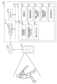
図1は、実施例1のシステムの構成例を示す図である。 Figure 1 shows an example of the system configuration of Example 1.
システムは、サーバ100及びユーザ端末101から構成される。サーバ100及びユーザ端末101は、ネットワーク105を介して接続される。ネットワーク105は、LAN(Local Area Network)及びWAN(Wide Area Network)等であり、接続方式は有線及び無線のいずれでもよい。
The system is composed of a
ユーザ端末101はユーザが操作する端末である。ユーザ端末101は、バッティング、ピッチング等の運動を行っている人を撮影した動画をサーバ100に送信する。また、ユーザ端末101は、サーバ100から送信される各種情報を表示する。ユーザ端末101は、例えば、図示しないプロセッサ、メモリ、ネットワークインタフェース、入力装置、及び出力装置等を有するパーソナルコンピュータ、又は、図示しないプロセッサ、メモリ、ネットワークインタフェース、撮像装置、入力装置、及び出力装置等を有するスマートフォンである。ユーザ端末101がパーソナルコンピュータである場合、本実施例では、ユーザ端末101としてスマートフォンを想定する。
The
サーバ100は、動画を用いて、運動時の人の部位間の同期性を分析し、分析結果をユーザに提示する。サーバ100は、プロセッサ110、メモリ111、及びネットワークインタフェース112を有する。なお、サーバ100は、HDD(Hard Disk Drive)及びSSD(Solid State Drive)等の記憶装置、キーボード、マウス、及びタッチパネル等の入力装置、並びに、ディスプレイ等の出力装置を有してもよい。
The
プロセッサ110は、サーバ100全体の制御を行う演算装置であり、メモリ111に格納されるプログラムを実行する。プロセッサ110がプログラムにしたがって処理を実行することによって、特定の機能を実現する機能部(モジュール)として動作する。以下の説明では、プログラムを主語に処理を説明する場合、プロセッサ110がプログラムを実行していることを示す。
The
メモリ111は、プロセッサ110が実行するプログラム及びプログラムが実行する情報を格納する記憶装置であり、例えば、揮発性又は不揮発性のメモリである。メモリ111はワークエリアとしても用いられる。メモリ111に格納されるプログラム及び情報については後述する。
ネットワークインタフェース112は、ネットワーク105を介して、ユーザ端末101等の外部装置と接続するためのインタフェースである。
The
ここで、メモリ111に格納されるプログラム及び情報について説明する。メモリ111は、プログラムとして、骨格認識プログラム120、同期性指標算出プログラム121、及び表示プログラム122を格納する。また、メモリ111は、情報として、動画DB130、動画管理DB131、骨格/特徴点管理DB132、同期性指標管理DB133、及び表示設定DB134を格納する。
Here, we will explain the programs and information stored in
動画DB130は、動画を管理するためのデータベースである。本実施例は、動画の形式、及び動画のフレームレートに限定されない。 Video DB130 is a database for managing videos. This embodiment is not limited to the video format and video frame rate.
動画管理DB131は、動画のメタデータを管理するためのデータベースである。動画管理DB131のデータ構造については図2を用いて説明する。 Video management DB131 is a database for managing metadata of videos. The data structure of video management DB131 will be explained using Figure 2.
骨格/特徴点管理DB132は、動画を構成する1フレームの画像における人の身体部位及び特徴点の座標を管理するためのデータベースである。ここで、特徴点は、例えば、人の重心である。なお、道具を用いる運動については、当該道具の重心等も特徴点として扱う。 The skeleton/feature point management DB132 is a database for managing the coordinates of a person's body parts and feature points in one frame of an image that constitutes a video. Here, a feature point is, for example, the center of gravity of a person. Note that for exercises that use tools, the center of gravity of the tool is also treated as a feature point.
以下の説明では、肘、膝、肩、足首等の人の身体部位、及び特徴点、すなわち、運動における可動部位を示す点を要素点と記載する。骨格/特徴点管理DB132のデータ構造の詳細は図3を用いて説明する。
In the following explanation, human body parts such as elbows, knees, shoulders, and ankles, as well as feature points, i.e., points that indicate movable parts in movement, are referred to as element points. Details of the data structure of the skeleton/feature
同期性指標管理DB133は、運動中における要素点間の因果関係、すなわち、要素点間の同期性を評価するための同期性指標を管理するためのデータベースである。同期性指標管理DB133のデータ構造の詳細は図4を用いて説明する。 The synchrony index management DB133 is a database for managing synchrony indexes for evaluating the causal relationship between element points during exercise, i.e., the synchrony between element points. Details of the data structure of the synchrony index management DB133 will be explained using FIG. 4.
表示設定DB134は、分析結果の表示に関する設定を管理するためのデータベースである。表示設定DB134には、提示する内容、及び提示する画面のレイアウト等に関する設定情報が格納される。 The display setting DB134 is a database for managing settings related to the display of analysis results. The display setting DB134 stores setting information related to the content to be presented and the layout of the screen to be presented, etc.
図2は、実施例1の動画管理DB131のデータ構造の一例を示す図である。 Figure 2 is a diagram showing an example of the data structure of video management DB131 in Example 1.
動画管理DB131は、動画ID201、撮影日時202、データ名203、選手名204、分類205、場所206、天候207、及びコメント208を含むエントリを格納する。一つのエントリが一つの動画に対応する。なお、エントリに含まれるフィールドは前述したものに限定されない。前述したフィールドのいずれかを含まなくてもよいし、また、他のフィールドを含んでもよい。
The
動画ID201は、動画の識別情報を格納するフィールドである。撮影日時202は、動画が撮影された日時を格納するフィールドである。データ名203は、動画の名称を格納するフィールドである。ファイル形式の動画の場合、データ名203にはファイル名が格納される。
選手名204は、動画中において運動を行っている人の氏名を格納するフィールドである。分類205は、運動の種別を格納するフィールドである。場所206は、運動が行われた場所に関する情報を格納するフィールドである。天候207は、運動時の天候に関する情報を格納するフィールドである。コメント208は、運動に関するコメントを格納するフィールドである。
図3は、実施例1の骨格/特徴点管理DB132のデータ構造の一例を示す図である。
Figure 3 is a diagram showing an example of the data structure of the skeleton/feature
骨格/特徴点管理DB132は、動画ID301、時間302、及び座標303を含むエントリを格納する。一つのエントリが一つの動画に対応する。一つのエントリには、フレームの数だけ時間及び座標から構成される行が含まれる。なお、エントリに含まれるフィールドは前述したものに限定されない。前述したフィールドのいずれかを含まなくてもよいし、また、他のフィールドを含んでもよい。
The skeleton/feature
動画ID301は、動画ID201と同一のフィールドである。時間302は、動画を構成する1フレームの画像(静止画像)の動画中の時間を格納するフィールドである。座標303は、静止画像における要素点の座標を格納するフィールド群である。座標303には、要素点ごとのフィールドが含まれる。
図4は、実施例1の同期性指標管理DB133のデータ構造の一例を示す図である。 Figure 4 is a diagram showing an example of the data structure of the synchronicity index management DB133 in Example 1.
同期性指標管理DB133は、動画ID401、分析時間範囲402、及び同期性指標403を含むエントリを格納する。一つのエントリが一つの動画に対応する。なお、エントリに含まれるフィールドは前述したものに限定されない。前述したフィールドのいずれかを含まなくてもよいし、また、他のフィールドを含んでもよい。
The synchrony
動画ID401は、動画ID201と同一のフィールドである。分析時間範囲402は、同期性指標を算出するために用いた動画の時間範囲を格納するフィールドである。同期性指標403は、要素点間の同期性指標を格納するフィールド群である。同期性指標403には、要素点ペアごとのフィールドが含まれる。
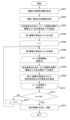
図5は、実施例1のサーバ100が実行する処理の概要を説明するフローチャートである。図6A及び図6Bは、実施例1のサーバ100によって算出される要素点の具体例を示す図である。図7は、実施例1のサーバ100による要素点の移動量の算出例を示す図である。
FIG. 5 is a flowchart outlining the process executed by the
サーバ100は、ユーザ端末101から動画又は分析対象の動画を指定する情報、及び分析時間範囲を含む分析要求を受信した場合、以下で説明する処理を実行する。なお、分析対象の動画を指定する情報は、例えば、動画の名称、運動の種類、及び氏名等である。分析時間範囲は、動画中の分析する画像の範囲を指定するための情報である。
When the
骨格認識プログラム120は、動画を用いて骨格/特徴点算出処理を実行する(ステップS101)。具体的には、以下のような処理が実行される。 The skeleton recognition program 120 executes a skeleton/feature point calculation process using a video (step S101). Specifically, the following process is executed:
(S101-1)骨格認識プログラム120は、動画から1フレームの画像を取得し、当該画像から要素点を特定し、特定された要素点の座標を算出する。例えば、図6A及び図6Bのような要素点が特定される。丸のマークは身体部位を表し、星及び三角のマークは特徴点を表す。骨格認識プログラム120は、身体部位を結合することによって人の骨格を認識できる。なお、身体部位及び特徴点の特定方法は、特許文献1等、公知の技術を用いればよいため詳細な説明は省略する。
(S101-1) The skeleton recognition program 120 acquires one frame of an image from the video, identifies element points from the image, and calculates the coordinates of the identified element points. For example, element points such as those shown in Figures 6A and 6B are identified. Circle marks represent body parts, and star and triangular marks represent feature points. The skeleton recognition program 120 can recognize a person's skeleton by combining body parts. Note that the method of identifying body parts and feature points can be done using publicly known technology such as that described in
(S101-2)骨格認識プログラム120は、骨格/特徴点管理DB132を参照し、動画ID301に分析対象の動画の識別情報が格納されるエントリを検索する。
(S101-2) The skeleton recognition program 120 refers to the skeleton/feature
エントリが存在しない場合、骨格認識プログラム120は、エントリを追加し、動画ID301に動画の識別情報を設定する。骨格認識プログラム120は、エントリに時間302及び座標303を含む行を一つ追加し、追加された行の時間302に画像の時間を設定する。また、骨格認識プログラム120は、追加された行の座標303の各フィールドに、各要素点の座標を設定する。
If an entry does not exist, the skeleton recognition program 120 adds an entry and sets the video identification information to the
エントリが存在する場合、骨格認識プログラム120は、当該エントリに時間302及び座標303を含む行を一つ追加し、追加された行の時間302に画像の時間を設定する。また、骨格認識プログラム120は、追加された行の座標303の各フィールドに、各要素点の座標を設定する。
If an entry exists, the skeleton recognition program 120 adds a row including a
全ての画像について処理が完了していない場合、骨格認識プログラム120はS101-1に戻り、同様の処理を実行する。全ての画像について処理が完了した場合、骨格認識プログラム120はステップS101の処理を終了する。以上がステップS101の処理の説明である。 If processing has not been completed for all images, the skeleton recognition program 120 returns to S101-1 and executes the same processing. If processing has been completed for all images, the skeleton recognition program 120 ends the processing of step S101. This concludes the description of the processing of step S101.
次に、骨格認識プログラム120は、動画に対してダウンサンプリングを実行する(ステップS102)。なお、ダウンサンプリングは省略してもよい。 Next, the skeleton recognition program 120 performs downsampling on the video (step S102). Note that downsampling may be omitted.
次に、骨格認識プログラム120は、移動量算出処理を実行する(ステップS103)。具体的には、以下のような処理が実行される。 Next, the skeleton recognition program 120 executes a movement amount calculation process (step S103). Specifically, the following process is executed.
(S103-1)骨格認識プログラム120は、要素点の中から対象の要素点を選択する。 (S103-1) The skeleton recognition program 120 selects a target element point from among the element points.
(S103-2)骨格認識プログラム120は、骨格/特徴点管理DB132の動画に対応するエントリを参照し、ダウンサンプリングされた動画に含まれる画像に対応する行から選択された要素点の座標を取得する。
(S103-2) The skeleton recognition program 120 references the entry corresponding to the video in the skeleton/feature
(S103-3)骨格認識プログラム120は、各時間の要素点の座標を用いて要素点の移動量の時系列データを生成する。 (S103-3) The skeleton recognition program 120 generates time series data of the movement amount of the element points using the coordinates of the element points at each time.
例えば、図7に示すように、時間t1の要素点の座標を(Xt1,Yt1)、時間t2の要素点の座標を(Xt2,Yt2)とした場合、時間t1から時間t2の間における要素点の移動量Vt2は式(1)を用いて算出できる。 For example, as shown in FIG. 7, if the coordinates of an element point at time t1 are ( Xt1 , Yt1 ) and the coordinates of the element point at time t2 are ( Xt2 , Yt2 ), the amount of movement Vt2 of the element point between time t1 and time t2 can be calculated using equation (1).

連続する画像に対して同様の処理を繰り返すことによって、要素点の移動量の時系列データが生成される。 By repeating the same process for successive images, time series data of the movement of element points is generated.
全ての要素点について処理が完了していない場合、骨格認識プログラム120はS103-1に戻り、同様の処理を実行する。全ての要素点について処理が完了した場合、骨格認識プログラム120はステップS103の処理を終了する。以上がステップS103の処理の説明である。 If processing has not been completed for all element points, the skeleton recognition program 120 returns to S103-1 and executes the same processing. If processing has been completed for all element points, the skeleton recognition program 120 ends the processing of step S103. This concludes the explanation of the processing of step S103.
次に、同期性指標算出プログラム121は、要素点の移動量の時系列データを用いて同期性指標算出処理を実行する(ステップS104)。同期性指標算出処理の詳細は図8から図10を用いて説明する。
Next, the synchrony
次に、表示プログラム122は、同期性指標を用いて表示処理を実行する(ステップS105)。その後、サーバ100は処理を終了する。表示処理の詳細は図11から図19を用いて説明する。
Next, the
図8は、実施例1のサーバ100が実行する同期性指標算出処理の一例を説明するフローチャートである。図9は、実施例1のサーバ100が実行する同期性指標算出処理の具体的な処理内容のイメージ図である。図10は、実施例1のサーバ100による同期性指標の具体的な算出方法の一例を示す図である。
FIG. 8 is a flowchart illustrating an example of a synchrony index calculation process executed by the
同期性指標算出プログラム121は、要素点のループ処理を開始する(ステップS201)。具体的には、同期性指標算出プログラム121は、要素点の中から対象の要素点を選択する。
The synchrony
次に、同期性指標算出プログラム121は、図9に示すように、選択した要素点の移動量の時系列データに基づいて、移動量の頻度ヒストグラムを生成する(ステップS202)。
Next, the synchrony
次に、同期性指標算出プログラム121は、スタージェスの公式を用いて移動量の頻度ヒストグラムの分割数を算出し、図9に示すように、当該分割数に基づいてヒストグラムを分割する(ステップS203)。
Next, the synchrony
次に、同期性指標算出プログラム121は、移動量を確率変数として扱えるように正規化し、また、ヒストグラムの分割結果に基づいて、移動量の時系列データを離散化する(ステップS204)。以下の説明では、ステップS204の処理によって生成される時系列データを確率変数時系列データと記載する。
Next, the synchrony
正規化を行うことによって、身体的な特性及び動画の特性(画角、撮影距離等)による要素点の移動量の大きさの違いを解消できる。また、離散化を行うことによって、移動エントロピーを算出することができる。 Normalization can eliminate differences in the amount of movement of element points due to physical characteristics and video characteristics (angle of view, shooting distance, etc.). In addition, discretization can be used to calculate the movement entropy.
次に、同期性指標算出プログラム121は、全ての要素点について処理が完了したか否かを判定する(ステップS205)。
Next, the synchrony
全ての要素点について処理が完了していない場合、同期性指標算出プログラム121は、ステップS201に戻り、同様の処理を実行する。
If processing has not been completed for all element points, the synchrony
全ての要素点について処理が完了した場合、同期性指標算出プログラム121は、要素点の確率変数時系列データを用いて、要素点間の移動エントロピーを算出する(ステップS206)。その後、同期性指標算出プログラム121は同期性指標算出処理を終了する。
When the processing for all element points is completed, the synchrony
例えば、図10に示すように、要素点Iのm個の確率変数時系列データと、要素点jのm個の確率変数時系列データとを用いて、時間ステップn+1における要素点Jから要素点Iの移動エントロピーは式(2)で算出できる。関数Pは確率を表す。 For example, as shown in FIG. 10, using m random variable time series data of element point I and m random variable time series data of element point j, the transfer entropy from element point J to element point I at time step n+1 can be calculated using formula (2). The function P represents probability.

同期性指標算出プログラム121は、同期性指標管理DB133にエントリを追加し、追加されたエントリの動画ID401に動画の識別情報を設定し、分析時間範囲402に分析時間範囲を設定する。なお、特に分析時間範囲が指定されていない場合、動画の開始時間から終了時間までが分析時間範囲として設定される。また、同期性指標算出プログラム121は、追加されたエントリの同期性指標403の各フィールドに、算出された移動エントロピーを設定する。
The synchrony
なお、同期性指標403の「右肩-右肘」は、右肩から右肘への移動エントロピーを格納するフィールドである。したがって、同期性指標403には、「右肩-右肘」とは別に「右肘-右肩」のフィールドも存在する。
Note that "right shoulder-right elbow" in the
次に、図11から図19を用いて表示処理について説明する。表示処理は、ユーザが要求する表示内容及び表示方法によって処理内容が異なる。 Next, the display process will be described with reference to Figures 11 to 19. The display process differs depending on the display content and display method requested by the user.
図11は、実施例1のサーバ100が実行する表示処理の一例を説明するフローチャートである。図12は、実施例1のサーバ100が提示する情報の一例を示す図である。
FIG. 11 is a flowchart illustrating an example of a display process executed by the
表示プログラム122は、同期性指標管理DB133から分析対象の動画の同期性指標を取得する(ステップS301)。
The
表示プログラム122は、同期性指標が閾値より大きい要素点ペアを抽出する(ステップS302)。
The
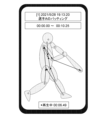
表示プログラム122は、抽出された要素点ペアを構成する二つの要素点を結ぶ矢印が描写された身体モデルの画像を表示するための表示情報を生成し、ユーザ端末101に送信する(ステップS303)。身体モデルは、外観及び身体部位に対応する要素点が定義された身体のモデルである。
The
ユーザ端末101には、例えば、図12に示すような画面が表示される。図12に示す画面には、動画の撮影日時、動作を行っている人の氏名、分析時間範囲、及び身体モデルの画像が表示される。身体モデルの画像には抽出された要素点ペアを構成する二つの要素点を結ぶ矢印が描写されている。なお、同期性指標の大きさに応じて矢印の太さ又は色を変更してもよい。
For example, a screen such as that shown in FIG. 12 is displayed on the
図13は、実施例1のサーバ100が実行する表示処理の一例を説明するフローチャートである。図14及び図15は、実施例1のサーバ100が提示する情報の一例を示す図である。
Figure 13 is a flowchart illustrating an example of a display process executed by the
表示プログラム122は、同期性指標管理DB133から分析対象の動画の同期性指標を取得する(ステップS401)。
The
表示プログラム122は、動画DB130から分析対象の動画を取得し、また、骨格/特徴点管理DB132から要素点の座標を取得する(ステップS402)。
The
表示プログラム122は、同期性指標が閾値より大きい要素点ペアを抽出する(ステップS403)。
The
表示プログラム122は、要素点の座標、同期性指標、動画に基づいて、要素点及び抽出された要素点ペアを構成する二つの要素点を結ぶ矢印が描写された動画を表示するための表示情報を生成し、ユーザ端末101に送信する(ステップS404)。
Based on the coordinates of the element points, the synchronicity index, and the video, the
ユーザ端末101には、例えば、図14に示すような画面が表示される。図14に示す画面には、動画の撮影日時、運動を行っている人の氏名、分析時間範囲、再生時間、及び動画が表示される。動画には要素点及び抽出された要素点ペアを構成する二つの要素点を結ぶ矢印が描写されている。なお、同期性指標の大きさに応じて矢印の太さ又は色を変更してもよい。
For example, a screen such as that shown in FIG. 14 is displayed on the
なお、図15に示すように、サーバ100は、二つの動画の入力を受け付け、各動画の要素点の同期性を比較可能な画面を表示してもよい。
As shown in FIG. 15, the
図16は、実施例1のサーバ100が実行する表示処理の一例を説明するフローチャートである。図17は、実施例1のサーバ100が提示する情報の一例を示す図である。
Figure 16 is a flowchart illustrating an example of a display process executed by the
以下の説明では、サーバ100は、ユーザから目的要素点及び最大階層数Nに関する情報を受け付けているものとする。
In the following explanation, it is assumed that the
表示プログラム122は、同期性指標管理DB133から分析対象の動画の同期性指標を取得する(ステップS501)。
The
表示プログラム122は、動画DB130から分析対象の動画を取得し、また、骨格/特徴点管理DB132から要素点の座標を取得する(ステップS502)。
The
表示プログラム122は、目的要素点を含み、かつ、同期性指標が閾値以上である要素点ペアを抽出する(ステップS503)。
The
表示プログラム122は、抽出された要素点ペアに基づいて、第1階層の要素点リストを生成する(ステップS504)。具体的には、表示プログラム122は、各要素点ペアについて、目的要素点と異なる要素点を取得し、第1階層の要素点リストに登録する。
The
表示プログラム122は、階層を示す変数nに1を設定する(ステップS505)。
The
表示プログラム122は、第n階層の要素点リストを取得し(ステップS506)、要素点のループ処理を開始する(ステップS507)。具体的には、表示プログラム122は、要素点リストから一つの要素点を選択する。以下の説明では、選択された要素点を起点要素点と記載する。
The
表示プログラム122は、起点要素点を含み、かつ、同期性指標が閾値以上である要素点ペアを抽出する(ステップS508)。
The
表示プログラム122は、抽出された要素点ペアに基づいて、第n+1階層の要素点リストを生成する(ステップS509)。具体的には、表示プログラム122は、各要素点ペアについて、起点要素点と異なる要素点を取得し、第n+1階層の要素点リストに登録する。
The
表示プログラム122は、第n階層の要素点リストの全ての要素点について処理が完了したか否かを判定する(ステップS510)。
The
第n階層の要素点リストの全ての要素点について処理が完了していない場合、表示プログラム122は、ステップS507に戻り、同様の処理を実行する。
If processing has not been completed for all element points in the element point list of the nth hierarchical level, the
第n階層の要素点リストの全ての要素点について処理が完了した場合、表示プログラム122は、n+1が最大階層数Nに一致するか否かを判定する(ステップS511)。
When processing has been completed for all element points in the element point list of the nth hierarchical level, the
n+1が最大階層数Nに一致しない場合、表示プログラム122は、変数nに1を加算した値を変数nに設定し(ステップS512)、その後、ステップS506に戻る。
If n+1 does not match the maximum number of hierarchical levels N, the
n+1が最大階層数Nに一致する場合、表示プログラム122は、要素点リスト、要素点の座標、同期性指標、及び動画に基づいて、要素点及び抽出された要素点ペアを構成する二つの要素点を結ぶ矢印が描写された動画を表示するための表示情報を生成し、ユーザ端末101に送信する(ステップS513)。
If n+1 matches the maximum number of hierarchical levels N, the
ユーザ端末101には、例えば、図17に示すような画面が表示される。図17に示す画面には、動画の撮影日時、運動を行っている人の氏名、分析時間範囲、再生時間、及び動画が表示される。動画には、要素点とともに、目的要素点を起点とした、同期性の高い要素点のつながりを示す矢印が描写されている。なお、同期性指標の大きさに応じて矢印の太さ又は色を変更してもよい。
For example, a screen such as that shown in FIG. 17 is displayed on the
図18は、実施例1のサーバ100が実行する表示処理の一例を説明するフローチャートである。図19は、実施例1のサーバ100が提示する情報の一例を示す図である。
Figure 18 is a flowchart illustrating an example of a display process executed by the
表示プログラム122は、同期性指標管理DB133から分析対象の動画の同期性指標を取得する(ステップS601)。
The
表示プログラム122は、動画DB130から分析対象の動画を取得し、また、骨格/特徴点管理DB132から要素点の座標を取得する(ステップS602)。
The
表示プログラム122は、同期性指標が閾値より大きい要素点ペアを抽出する(ステップS603)。
The
表示プログラム122は、抽出された要素点ペアの接続が構成するネットワークにおける要素点の重要性を表すネットワーク指標を算出する(ステップS604)。例えば、ページランク等の中心性指標がネットワーク指標として算出される。
The
表示プログラム122は、要素点の座標、動画、及びネットワーク指標に基づいて、ネットワーク指標が閾値より大きい要素点を強調表示した動画を表示するための表示情報を生成し、ユーザ端末101に送信する(ステップS605)。
Based on the coordinates of the element points, the video, and the network index, the
ユーザ端末101には、例えば、図19に示すような画面が表示される。図19に示す画面には、動画の撮影日時、運動を行っている人の氏名、分析時間範囲、再生時間、及び動画が表示される。動画には要素点が描写されている。ネットワーク指標が閾値より大きい要素点は、大きさ又は色等を変えて強調表示される。
For example, a screen such as that shown in FIG. 19 is displayed on the
以上で説明したように、実施例1によれば、サーバ100は、人の身体部位間及び身体部位と道具との間の同期性を定量的に評価し、評価結果を提示することができる。これによって、ユーザは、運動時の人の身体部位間及び身体部位と道具との間の同期性を把握することができる。
As described above, according to the first embodiment, the
なお、複数のサーバ100から構成される分析システムを用いて同様の機能を実現してもよい。この場合、各サーバ100に機能を分散した配置してもよい。
Note that similar functions may be achieved using an analysis system consisting of
なお、サーバ100が有するプログラムは、複数のプログラムを一つのプログラムにまとめてもよいし、一つのプログラムを機能ごとに複数のプログラムに分けてもよい。
The programs held by the
実施例2では、一つの動画について、単位時間範囲ごとに同期性指標を算出する点が異なる。これによって、運動時における身体部位の同期性の時間変化を把握することができる。以下、実施例1との差異を中心に実施例2について説明する。 Example 2 differs in that a synchrony index is calculated for each unit time range for one video. This makes it possible to grasp the change over time in synchrony between body parts during exercise. Below, Example 2 will be explained, focusing on the differences from Example 1.
実施例2のシステムの構成は実施例1と同一である。実施例2のサーバ100のハードウェア構成及びソフトウェア構成は実施例1と同一である。実施例2の動画DB130、動画管理DB131、骨格/特徴点管理DB132、及び表示設定DB134のデータ構造は実施例1と同一である。
The system configuration of Example 2 is the same as that of Example 1. The hardware configuration and software configuration of the
実施例2では、同期性指標管理DB133のデータ構造が異なる。図20は、実施例2の同期性指標管理DB133のデータ構造の一例を示す図である。
In the second embodiment, the data structure of the synchrony
実施例2の同期性指標管理DB133に格納されるエントリを構成するフィールドの構造は実施例1と同一である。ただし、一つのエントリには、単位時間範囲ごとの同期性指標を格納する行が含まれる。単位時間範囲は、システム全体で共通する値でもよいし、動画ごとに異なる値でもよい。
The structure of the fields constituting the entries stored in the synchrony
図21は、実施例2のサーバ100が実行する処理の概要を説明するフローチャートである。
Figure 21 is a flowchart outlining the processing executed by the
ステップS101からステップS103の処理が実行された後、同期性指標算出プログラム121は、時間を表す変数tに分析開始時間を設定する(ステップS111)。
After the processing of steps S101 to S103 is executed, the synchrony
次に、同期性指標算出プログラム121は、単位時間範囲[t,t+l]の要素点の移動量の時系列データを取得する(ステップS112)。単位時間範囲は、任意のウィンドウ幅lのウィンドウを時系列に沿ってスライドさせることによって切り出される時間範囲である。
Next, the synchrony
次に、同期性指標算出プログラム121は、要素点の移動量の時系列データを用いて同期性指標算出処理を実行する(ステップS104)。同期性指標算出処理は実施例1と同一の処理であるが、処理に用いる時系列データの範囲が異なる。実施例1では分析時間範囲全体の時系列データを対象としていたが、実施例2では、単位時間範囲[t,t+l]の時系列データを対象とする。また、同期性指標算出プログラム121は、エントリに単位時間範囲[t,t+l]の行を追加し、当該行の同期性指標403に算出された同期性指標を設定する。
Next, the synchrony
次に、同期性指標算出プログラム121は、時間(t+l+Δt)が分析終了時間より後であるか否かを判定する(ステップS113)。ここで、Δtは更新時間幅を表す。更新時間幅は予め設定されるものとする。なお、動画ごとに異なる値でもよい。
Next, the synchrony
時間(t+l+Δt)が分析終了時間に一致又は分析終了時間より前である場合、同期性指標算出プログラム121は、変数tの値に更新時間幅Δtを追加した時間を変数tに設定し(ステップS114)、その後、ステップS112に戻る。
If the time (t+l+Δt) coincides with or precedes the analysis end time, the synchrony
時間(t+l+Δt)が分析終了時間より後である場合、同期性指標算出プログラム121は、単位時間範囲ごとの同期性指標を用いて表示処理を実行する(ステップS105)。
If the time (t+l+Δt) is after the analysis end time, the synchrony
実施例2では時間の経過に伴って同期性指標が変化する。したがって、表示処理では、時間経過に伴って同期性指標を動的に変化させる表示が行われる。表示処理の処理内容は実施例1と同一であるため説明は省略する。 In the second embodiment, the synchrony index changes over time. Therefore, in the display process, a display is performed in which the synchrony index changes dynamically over time. The contents of the display process are the same as those in the first embodiment, so a description thereof is omitted.
実施例2によれば、運動時における身体部位間及び身体部位と道具との間の同期性の時間変化を把握することができる。 According to Example 2, it is possible to grasp the change over time in synchrony between body parts and between body parts and tools during exercise.
なお、本発明は上記した実施例に限定されるものではなく、様々な変形例が含まれる。また、例えば、上記した実施例は本発明を分かりやすく説明するために構成を詳細に説明したものであり、必ずしも説明した全ての構成を備えるものに限定されるものではない。また、各実施例の構成の一部について、他の構成に追加、削除、置換することが可能である。 The present invention is not limited to the above-described embodiments, but includes various modified examples. For example, the above-described embodiments are provided to explain the present invention in detail, and are not necessarily limited to those including all of the described configurations. In addition, it is possible to add, delete, or replace part of the configuration of each embodiment with another configuration.
また、上記の各構成、機能、処理部、処理手段等は、それらの一部又は全部を、例えば集積回路で設計する等によりハードウェアで実現してもよい。また、本発明は、実施例の機能を実現するソフトウェアのプログラムコードによっても実現できる。この場合、プログラムコードを記録した記憶媒体をコンピュータに提供し、そのコンピュータが備えるプロセッサが記憶媒体に格納されたプログラムコードを読み出す。この場合、記憶媒体から読み出されたプログラムコード自体が前述した実施例の機能を実現することになり、そのプログラムコード自体、及びそれを記憶した記憶媒体は本発明を構成することになる。このようなプログラムコードを供給するための記憶媒体としては、例えば、フレキシブルディスク、CD-ROM、DVD-ROM、ハードディスク、SSD(Solid State Drive)、光ディスク、光磁気ディスク、CD-R、磁気テープ、不揮発性のメモリカード、ROMなどが用いられる。 The above-mentioned configurations, functions, processing units, processing means, etc. may be realized in part or in whole by hardware, for example by designing them as integrated circuits. The present invention can also be realized by software program code that realizes the functions of the embodiments. In this case, a storage medium on which the program code is recorded is provided to a computer, and a processor included in the computer reads the program code stored in the storage medium. In this case, the program code itself read from the storage medium realizes the functions of the above-mentioned embodiments, and the program code itself and the storage medium on which it is stored constitute the present invention. Examples of storage media for supplying such program code include flexible disks, CD-ROMs, DVD-ROMs, hard disks, SSDs (Solid State Drives), optical disks, magneto-optical disks, CD-Rs, magnetic tapes, non-volatile memory cards, and ROMs.
また、本実施例に記載の機能を実現するプログラムコードは、例えば、アセンブラ、C/C++、perl、Shell、PHP、Python、Java(登録商標)等の広範囲のプログラム又はスクリプト言語で実装できる。 In addition, the program code that realizes the functions described in this embodiment can be implemented in a wide range of program or script languages, such as assembler, C/C++, perl, Shell, PHP, Python, Java (registered trademark), etc.
さらに、実施例の機能を実現するソフトウェアのプログラムコードを、ネットワークを介して配信することによって、それをコンピュータのハードディスクやメモリ等の記憶手段又はCD-RW、CD-R等の記憶媒体に格納し、コンピュータが備えるプロセッサが当該記憶手段や当該記憶媒体に格納されたプログラムコードを読み出して実行するようにしてもよい。 Furthermore, the program code of the software that realizes the functions of the embodiment may be distributed over a network and stored in a storage means such as a computer's hard disk or memory, or in a storage medium such as a CD-RW or CD-R, and the processor of the computer may read and execute the program code stored in the storage means or storage medium.
上述の実施例において、制御線や情報線は、説明上必要と考えられるものを示しており、製品上必ずしも全ての制御線や情報線を示しているとは限らない。全ての構成が相互に接続されていてもよい。 In the above examples, the control lines and information lines are those that are considered necessary for the explanation, and not all control lines and information lines in the product are necessarily shown. All components may be interconnected.
100 サーバ
101 ユーザ端末
105 ネットワーク
110 プロセッサ
111 メモリ
112 ネットワークインタフェース
120 骨格認識プログラム
121 同期性指標算出プログラム
122 表示プログラム
130 動画DB
131 動画管理DB
132 骨格/特徴点管理DB
133 同期性指標管理DB
134 表示設定DB
131 Video Management DB
132 Skeleton/feature point management DB
133 Synchrony index management DB
134 Display setting DB
Claims (13)
プロセッサ、前記プロセッサに接続されるメモリ、前記プロセッサに接続されるインタフェースを有する少なくとも一つの計算機を含み、
前記少なくとも一つの計算機は、
運動を行う人を撮像した動画を取得し、
前記動画を構成する複数の画像の各々について、運動における可動部位を表す複数の要素点の座標を算出し、前記画像と、前記複数の要素点の座標とを対応づけて前記メモリに格納し、
前記複数の画像の各々の前記複数の要素点の座標に基づいて、前記複数の要素点の各々の移動量の時系列データを生成し、
前記複数の要素点の移動量の時系列データを用いて、複数の要素点ペアの各々について、運動時の前記要素点間の同期性を評価するための同期性指標を算出し、前記複数の要素点ペアの前記同期性指標を前記メモリに格納し、
前記複数の要素点ペアの前記同期性指標に基づいて、運動時の前記要素点間の同期性を示す表示情報を生成し、出力し、
前記要素点ペアの前記同期性指標は、前記要素点ペアを構成する一つの要素点から前記要素点ペアを構成する他の要素点への移動エントロピーであり、
前記少なくとも一つの計算機は、前記同期性指標の算出する場合に、
前記複数の要素点の各々の移動量の時系列データを離散化し、
前記複数の要素点の各々の移動量の時系列データを確率変数として扱える値に正規化し、
離散化及び正規化が行われた前記複数の要素点の各々の移動量の時系列データを用いて、前記複数の要素点ペアの各々の前記同期性指標を算出することを特徴とする計算機システム。 A computer system for analyzing physical movements of a person performing exercise, comprising:
at least one computer having a processor, a memory coupled to the processor, and an interface coupled to the processor;
The at least one computer
Obtain a video of a person exercising,
Calculating the coordinates of a plurality of element points representing movable parts in a movement for each of a plurality of images constituting the video, and storing the image and the coordinates of the plurality of element points in the memory in association with each other;
generating time series data of the amount of movement of each of the element points based on coordinates of the element points of each of the images;
Using time series data of the amount of movement of the plurality of element points, a synchrony index is calculated for each of a plurality of element point pairs to evaluate synchrony between the element points during exercise, and the synchrony index of the plurality of element point pairs is stored in the memory;
generating and outputting display information indicating synchrony between the element points during exercise based on the synchrony indexes of the plurality of element point pairs;
the synchrony index of the element point pair is a transfer entropy from one element point constituting the element point pair to the other element point constituting the element point pair;
The at least one computer, when calculating the synchrony index,
discretizing time series data of the amount of movement of each of the plurality of element points;
Normalizing the time series data of the amount of movement of each of the plurality of element points into a value that can be treated as a random variable;
A computer system comprising: a computer that calculates the synchrony index for each of the plurality of element point pairs using time series data of the amount of movement of each of the plurality of element point pairs that has been discretized and normalized.
前記少なくとも一つの計算機は、The at least one computer
前記動画の分析時間範囲を設定し、Set the analysis time range of the video,
前記分析時間範囲に含まれる、前記複数の要素点の移動量の時系列データに基づいて、前記複数の要素点ペアの前記同期性指標を算出し、Calculating the synchrony index of the element point pairs based on time series data of the movement amounts of the element points included in the analysis time range;
前記分析時間範囲と、前記複数の要素点ペアの前記同期性指標とを対応づけて前記メモリに格納することを特徴とする計算機システム。The computer system is characterized in that the analysis time range and the synchrony index of the plurality of element point pairs are stored in the memory in association with each other.
前記少なくとも一つの計算機は、The at least one computer
前記動画の分析時間範囲を設定し、Set the analysis time range of the video,
前記分析時間範囲より小さい単位時間範囲ごとに、当該単位時間範囲に含まれる、前記複数の要素点の移動量の時系列データに基づいて、前記複数の要素点ペアの前記同期性指標を算出し、calculating the synchrony index of the element point pairs based on time series data of the movement amounts of the element points included in each unit time range smaller than the analysis time range;
前記単位時間範囲と、前記複数の要素点ペアの前記同期性指標とを対応づけて前記メモリに格納することを特徴とする計算機システム。The computer system is characterized in that the unit time range and the synchrony indexes of the plurality of element point pairs are stored in the memory in association with each other.
前記少なくとも一つの計算機は、前記複数の要素点ペアの前記同期性指標に基づいて、同期性が高い前記要素点ペアを構成する前記要素点を、他の前記要素点より強調して表示する前記表示情報を生成することを特徴とする計算機システム。The at least one computer is characterized in that the display information is generated based on the synchronicity index of the multiple element point pairs, in such a way that the element points that constitute the element point pairs with high synchronicity are displayed more emphatically than the other element points.
前記少なくとも一つの計算機は、The at least one computer
前記複数の要素点ペアの前記同期性指標に基づいて、目的要素点を起点に、前記同期性が高い前記要素点ペアを探索し、searching for the element point pair having high synchronicity, starting from a target element point, based on the synchronicity indexes of the plurality of element point pairs;
探索された前記要素点ペアを構成する前記要素点を、他の前記要素点より強調して表示する前記表示情報を生成することを特徴とする計算機システム。a display information generating unit that generates the display information so as to emphasize the element points constituting the searched element point pair more than the other element points;
前記少なくとも一つの計算機は、The at least one computer
前記複数の要素点ペアの前記同期性指標に基づいて、同期性が高い前記要素点ペアを特定し、Identifying the element point pairs having high synchrony based on the synchrony indexes of the plurality of element point pairs;
特定された前記要素点ペアから構成されるネットワークのネットワーク指標を算出し、Calculating a network index of a network composed of the identified element point pairs;
前記ネットワーク指標に基づいて、前記ネットワークにおいて重要な前記要素点を、他の前記要素点より強調して表示する前記表示情報を生成することを特徴とする計算機システム。a display information generating unit that generates, based on the network index, the display information emphasizing the element points that are important in the network more than the other element points;
前記少なくとも一つの計算機は、前記動画に重畳させて前記要素点を表示する前記表示情報を生成することを特徴とする計算機システム。The at least one computer generates the display information for displaying the element points by superimposing the display information on the moving image.
前記計算機システムは、プロセッサ、前記プロセッサに接続されるメモリ、前記プロセッサに接続されるインタフェースを有する少なくとも一つの計算機を含み、The computer system includes at least one computer having a processor, a memory coupled to the processor, and an interface coupled to the processor;
前記運動を行う人の身体動作の分析方法は、The method for analyzing the physical movement of a person performing exercise includes:
前記少なくとも一つの計算機が、運動を行う人を撮像した動画を取得する第1のステップと、a first step of acquiring, by the at least one computer, a video of a person performing an exercise;
前記少なくとも一つの計算機が、前記動画を構成する複数の画像の各々について、運動における可動部位を表す複数の要素点の座標を算出し、前記画像と、前記複数の要素点の座標とを対応づけて前記メモリに格納する第2のステップと、a second step in which the at least one computer calculates coordinates of a plurality of element points representing movable parts in a movement for each of a plurality of images constituting the moving image, and stores the image and the coordinates of the plurality of element points in the memory in correspondence with each other;
前記少なくとも一つの計算機が、前記複数の画像の各々の前記複数の要素点の座標に基づいて、前記複数の要素点の各々の移動量の時系列データを生成する第3のステップと、a third step of generating, by the at least one computer, time series data of the amount of movement of each of the plurality of element points based on coordinates of the plurality of element points of each of the plurality of images;
前記少なくとも一つの計算機が、前記複数の要素点の移動量の時系列データを用いて、複数の要素点ペアの各々について、運動時の前記要素点間の同期性を評価するための同期性指標を算出し、前記複数の要素点ペアの前記同期性指標を前記メモリに格納する第4のステップと、a fourth step in which the at least one computer calculates a synchrony index for evaluating synchrony between the element points during exercise for each of a plurality of element point pairs using time series data of the amount of movement of the plurality of element points, and stores the synchrony index for the plurality of element point pairs in the memory;
前記少なくとも一つの計算機が、前記複数の要素点ペアの前記同期性指標に基づいて、運動時の前記要素点間の同期性を示す表示情報を生成し、出力する第5のステップと、を含み、a fifth step of generating and outputting display information indicating synchrony between the element points during exercise based on the synchrony indexes of the plurality of element point pairs by the at least one computer;
前記要素点ペアの前記同期性指標は、前記要素点ペアを構成する一つの要素点から前記要素点ペアを構成する他の要素点への移動エントロピーであり、The synchrony index of the element point pair is a transfer entropy from one element point constituting the element point pair to the other element point constituting the element point pair,
前記第4のステップは、The fourth step includes:
前記少なくとも一つの計算機が、前記複数の要素点の各々の移動量の時系列データを離散化するステップと、The at least one computer discretizes time series data of the movement amount of each of the plurality of element points;
前記少なくとも一つの計算機が、前記複数の要素点の各々の移動量の時系列データを確率変数として扱える値に正規化するステップと、normalizing, by the at least one computer, time series data of the amount of movement of each of the plurality of element points into a value that can be treated as a random variable;
前記少なくとも一つの計算機が、離散化及び正規化が行われた前記複数の要素点の各々の移動量の時系列データを用いて、前記複数の要素点ペアの各々の前記同期性指標を算出するステップと、を含むことを特徴とする運動を行う人の身体動作の分析方法。and calculating, by the at least one computer, the synchrony index for each of the plurality of element point pairs using time series data of the amount of movement of each of the plurality of element points that have been discretized and normalized.
前記第4のステップは、The fourth step includes:
前記少なくとも一つの計算機が、前記動画の分析時間範囲を設定するステップと、said at least one computer setting an analysis time range for said video;
前記少なくとも一つの計算機が、前記分析時間範囲に含まれる、前記複数の要素点の移動量の時系列データに基づいて、前記複数の要素点ペアの前記同期性指標を算出するステップと、The at least one computer calculates the synchrony index of the plurality of element point pairs based on time series data of the movement amounts of the plurality of element points included in the analysis time range;
前記少なくとも一つの計算機が、前記分析時間範囲と、前記複数の要素点ペアの前記同期性指標とを対応づけて前記メモリに格納するステップと、を含むことを特徴とする運動を行う人の身体動作の分析方法。and storing, by the at least one computer, in the memory, the analysis time range and the synchrony index of the plurality of element point pairs in association with each other.
前記第4のステップは、The fourth step includes:
前記少なくとも一つの計算機が、前記動画の分析時間範囲を設定するステップと、said at least one computer setting an analysis time range for said video;
前記少なくとも一つの計算機が、前記分析時間範囲より小さい単位時間範囲ごとに、当該単位時間範囲に含まれる、前記複数の要素点の移動量の時系列データに基づいて、前記複数の要素点ペアの前記同期性指標を算出するステップと、The at least one computer calculates the synchrony index of the plurality of element point pairs based on time series data of the movement amounts of the plurality of element points included in each unit time range smaller than the analysis time range;
前記少なくとも一つの計算機が、前記単位時間範囲と、前記複数の要素点ペアの前記同期性指標とを対応づけて前記メモリに格納するステップと、を含むことを特徴とする運動を行う人の身体動作の分析方法。and storing, by the at least one computer, in the memory, the unit time range and the synchrony index of the plurality of element point pairs in association with each other.
前記第5のステップは、前記少なくとも一つの計算機が、前記複数の要素点ペアの前記同期性指標に基づいて、同期性が高い前記要素点ペアを構成する前記要素点を、他の前記要素点より強調して表示する前記表示情報を生成するステップを含むことを特徴とする運動を行う人の身体動作の分析方法。The fifth step is a method for analyzing the physical movements of a person performing exercise, characterized in that the at least one computer generates the display information in such a way that, based on the synchronicity index of the plurality of element point pairs, the element points that constitute the element point pairs having a high degree of synchronicity are displayed more emphatically than the other element points.
前記第5のステップは、The fifth step includes:
前記少なくとも一つの計算機が、前記複数の要素点ペアの前記同期性指標に基づいて、目的要素点を起点に、前記同期性が高い前記要素点ペアを探索するステップと、The at least one computer searches for the element point pair having high synchronicity, starting from a target element point, based on the synchronicity index of the plurality of element point pairs;
前記少なくとも一つの計算機が、探索された前記要素点ペアを構成する前記要素点を、他の前記要素点より強調して表示する前記表示情報を生成するステップと、を含むことを特徴とする運動を行う人の身体動作の分析方法。and generating, by the at least one computer, the display information for displaying the element points constituting the searched element point pair in a more emphasized manner than the other element points.
前記第5のステップは、The fifth step includes:
前記少なくとも一つの計算機が、前記複数の要素点ペアの前記同期性指標に基づいて、同期性が高い前記要素点ペアを特定するステップと、The at least one computer identifies the element point pairs having high synchronicity based on the synchronicity indexes of the plurality of element point pairs;
前記少なくとも一つの計算機が、特定された前記要素点ペアから構成されるネットワークのネットワーク指標を算出するステップと、A step of calculating a network index of a network composed of the identified element point pairs by the at least one computer;
前記少なくとも一つの計算機が、前記ネットワーク指標に基づいて、前記ネットワークにおいて重要な前記要素点を、他の前記要素点より強調して表示する前記表示情報を生成するステップと、を含むことを特徴とする運動を行う人の身体動作の分析方法。and generating, by the at least one computer, the display information based on the network index, which displays the element points that are important in the network in a more emphasized manner than the other element points.
Priority Applications (1)
| Application Number | Priority Date | Filing Date | Title |
|---|---|---|---|
| JP2021174388A JP7667724B2 (en) | 2021-10-26 | 2021-10-26 | Computer system and method for analyzing physical movements of a person performing exercise |
Applications Claiming Priority (1)
| Application Number | Priority Date | Filing Date | Title |
|---|---|---|---|
| JP2021174388A JP7667724B2 (en) | 2021-10-26 | 2021-10-26 | Computer system and method for analyzing physical movements of a person performing exercise |
Publications (2)
| Publication Number | Publication Date |
|---|---|
| JP2023064238A JP2023064238A (en) | 2023-05-11 |
| JP7667724B2 true JP7667724B2 (en) | 2025-04-23 |
Family
ID=86271445
Family Applications (1)
| Application Number | Title | Priority Date | Filing Date |
|---|---|---|---|
| JP2021174388A Active JP7667724B2 (en) | 2021-10-26 | 2021-10-26 | Computer system and method for analyzing physical movements of a person performing exercise |
Country Status (1)
| Country | Link |
|---|---|
| JP (1) | JP7667724B2 (en) |
Citations (1)
| Publication number | Priority date | Publication date | Assignee | Title |
|---|---|---|---|---|
| JP2005157942A (en) | 2003-11-28 | 2005-06-16 | National Institute Of Advanced Industrial & Technology | Motion body motion data segmentation processing device. |
-
2021
- 2021-10-26 JP JP2021174388A patent/JP7667724B2/en active Active
Patent Citations (1)
| Publication number | Priority date | Publication date | Assignee | Title |
|---|---|---|---|---|
| JP2005157942A (en) | 2003-11-28 | 2005-06-16 | National Institute Of Advanced Industrial & Technology | Motion body motion data segmentation processing device. |
Non-Patent Citations (1)
| Title |
|---|
| 上野 太一,スポーツ映像を対象とした時系列データ分析による習熟度別トレーニング支援システムの開発 A Sports-training Support System with Time-series Analytical Functions for Sports-video Database,第3回データ工学と情報マネジメントに関するフォーラム 論文集,2011年07月27日,P1-6 |
Also Published As
| Publication number | Publication date |
|---|---|
| JP2023064238A (en) | 2023-05-11 |
Similar Documents
| Publication | Publication Date | Title |
|---|---|---|
| Cioppa et al. | Scaling up SoccerNet with multi-view spatial localization and re-identification | |
| Xiao et al. | Recognizing sports activities from video frames using deformable convolution and adaptive multiscale features | |
| Zeng et al. | Grid anchor based image cropping: A new benchmark and an efficient model | |
| Jiang et al. | Seeing invisible poses: Estimating 3d body pose from egocentric video | |
| Chen et al. | LSTM with bio inspired algorithm for action recognition in sports videos | |
| Rangari et al. | Video based exercise recognition and correct pose detection | |
| CN103793721B (en) | Pedestrian repeat recognition method and system based on area related feedback | |
| CN112132866B (en) | Target object tracking method, device, equipment and computer readable storage medium | |
| US20240013410A1 (en) | Information processing apparatus, information processing method, and program | |
| Wan Idris et al. | A systematic survey of martial art using motion capture technologies: the importance of extrinsic feedback | |
| Pang et al. | Applications of AI in martial arts: A survey | |
| MacRitchie et al. | Efficient tracking of pianists’ finger movements | |
| Chen et al. | Quantitative analysis and evaluation of research on the application of computer vision in sports since the 21st century | |
| CN106874365A (en) | Tracking based on social event on Social Media platform | |
| Xia et al. | Video visualization and visual analytics: A task-based and application-driven investigation | |
| JP7667724B2 (en) | Computer system and method for analyzing physical movements of a person performing exercise | |
| Connaghan et al. | An automatic visual analysis system for tennis | |
| CN115546893A (en) | A cheerleading video evaluation visualization method and system | |
| JP7310929B2 (en) | Exercise menu evaluation device, method, and program | |
| CN116958859B (en) | Golf swing evaluation method and system based on video | |
| CN118718339A (en) | Sports assistance system and sports assistance method | |
| Jlidi et al. | Enhancing Human Action Recognition Through Transfer Learning and Body Articulation Analysis | |
| JP7429016B2 (en) | Image processing method, computer program and image processing device | |
| Ryu et al. | A deep learning model based on sequential object feature accumulation for sport activity recognition | |
| Li | Visualization of movements in sports training based on multimedia information processing technology |
Legal Events
| Date | Code | Title | Description |
|---|---|---|---|
| A621 | Written request for application examination |
Free format text: JAPANESE INTERMEDIATE CODE: A621 Effective date: 20240220 |
|
| A977 | Report on retrieval |
Free format text: JAPANESE INTERMEDIATE CODE: A971007 Effective date: 20241108 |
|
| A131 | Notification of reasons for refusal |
Free format text: JAPANESE INTERMEDIATE CODE: A131 Effective date: 20250107 |
|
| A521 | Request for written amendment filed |
Free format text: JAPANESE INTERMEDIATE CODE: A523 Effective date: 20250307 |
|
| TRDD | Decision of grant or rejection written | ||
| A01 | Written decision to grant a patent or to grant a registration (utility model) |
Free format text: JAPANESE INTERMEDIATE CODE: A01 Effective date: 20250401 |
|
| A61 | First payment of annual fees (during grant procedure) |
Free format text: JAPANESE INTERMEDIATE CODE: A61 Effective date: 20250411 |
|
| R150 | Certificate of patent or registration of utility model |
Ref document number: 7667724 Country of ref document: JP Free format text: JAPANESE INTERMEDIATE CODE: R150 |