JP7672190B2 - Image encoding device, image decoding device, and control method and program thereof - Google Patents
Image encoding device, image decoding device, and control method and program thereof Download PDFInfo
- Publication number
- JP7672190B2 JP7672190B2 JP2018235910A JP2018235910A JP7672190B2 JP 7672190 B2 JP7672190 B2 JP 7672190B2 JP 2018235910 A JP2018235910 A JP 2018235910A JP 2018235910 A JP2018235910 A JP 2018235910A JP 7672190 B2 JP7672190 B2 JP 7672190B2
- Authority
- JP
- Japan
- Prior art keywords
- quantization matrix
- quantization
- value
- values
- image
- Prior art date
- Legal status (The legal status is an assumption and is not a legal conclusion. Google has not performed a legal analysis and makes no representation as to the accuracy of the status listed.)
- Active
Links
Images




Classifications
-
- H—ELECTRICITY
- H04—ELECTRIC COMMUNICATION TECHNIQUE
- H04N—PICTORIAL COMMUNICATION, e.g. TELEVISION
- H04N19/00—Methods or arrangements for coding, decoding, compressing or decompressing digital video signals
- H04N19/10—Methods or arrangements for coding, decoding, compressing or decompressing digital video signals using adaptive coding
- H04N19/102—Methods or arrangements for coding, decoding, compressing or decompressing digital video signals using adaptive coding characterised by the element, parameter or selection affected or controlled by the adaptive coding
- H04N19/124—Quantisation
- H04N19/126—Details of normalisation or weighting functions, e.g. normalisation matrices or variable uniform quantisers
-
- H—ELECTRICITY
- H04—ELECTRIC COMMUNICATION TECHNIQUE
- H04N—PICTORIAL COMMUNICATION, e.g. TELEVISION
- H04N19/00—Methods or arrangements for coding, decoding, compressing or decompressing digital video signals
- H04N19/10—Methods or arrangements for coding, decoding, compressing or decompressing digital video signals using adaptive coding
- H04N19/102—Methods or arrangements for coding, decoding, compressing or decompressing digital video signals using adaptive coding characterised by the element, parameter or selection affected or controlled by the adaptive coding
- H04N19/119—Adaptive subdivision aspects, e.g. subdivision of a picture into rectangular or non-rectangular coding blocks
-
- H—ELECTRICITY
- H04—ELECTRIC COMMUNICATION TECHNIQUE
- H04N—PICTORIAL COMMUNICATION, e.g. TELEVISION
- H04N19/00—Methods or arrangements for coding, decoding, compressing or decompressing digital video signals
- H04N19/10—Methods or arrangements for coding, decoding, compressing or decompressing digital video signals using adaptive coding
- H04N19/102—Methods or arrangements for coding, decoding, compressing or decompressing digital video signals using adaptive coding characterised by the element, parameter or selection affected or controlled by the adaptive coding
- H04N19/124—Quantisation
-
- H—ELECTRICITY
- H04—ELECTRIC COMMUNICATION TECHNIQUE
- H04N—PICTORIAL COMMUNICATION, e.g. TELEVISION
- H04N19/00—Methods or arrangements for coding, decoding, compressing or decompressing digital video signals
- H04N19/10—Methods or arrangements for coding, decoding, compressing or decompressing digital video signals using adaptive coding
- H04N19/102—Methods or arrangements for coding, decoding, compressing or decompressing digital video signals using adaptive coding characterised by the element, parameter or selection affected or controlled by the adaptive coding
- H04N19/132—Sampling, masking or truncation of coding units, e.g. adaptive resampling, frame skipping, frame interpolation or high-frequency transform coefficient masking
-
- H—ELECTRICITY
- H04—ELECTRIC COMMUNICATION TECHNIQUE
- H04N—PICTORIAL COMMUNICATION, e.g. TELEVISION
- H04N19/00—Methods or arrangements for coding, decoding, compressing or decompressing digital video signals
- H04N19/10—Methods or arrangements for coding, decoding, compressing or decompressing digital video signals using adaptive coding
- H04N19/134—Methods or arrangements for coding, decoding, compressing or decompressing digital video signals using adaptive coding characterised by the element, parameter or criterion affecting or controlling the adaptive coding
- H04N19/136—Incoming video signal characteristics or properties
-
- H—ELECTRICITY
- H04—ELECTRIC COMMUNICATION TECHNIQUE
- H04N—PICTORIAL COMMUNICATION, e.g. TELEVISION
- H04N19/00—Methods or arrangements for coding, decoding, compressing or decompressing digital video signals
- H04N19/10—Methods or arrangements for coding, decoding, compressing or decompressing digital video signals using adaptive coding
- H04N19/134—Methods or arrangements for coding, decoding, compressing or decompressing digital video signals using adaptive coding characterised by the element, parameter or criterion affecting or controlling the adaptive coding
- H04N19/157—Assigned coding mode, i.e. the coding mode being predefined or preselected to be further used for selection of another element or parameter
-
- H—ELECTRICITY
- H04—ELECTRIC COMMUNICATION TECHNIQUE
- H04N—PICTORIAL COMMUNICATION, e.g. TELEVISION
- H04N19/00—Methods or arrangements for coding, decoding, compressing or decompressing digital video signals
- H04N19/10—Methods or arrangements for coding, decoding, compressing or decompressing digital video signals using adaptive coding
- H04N19/134—Methods or arrangements for coding, decoding, compressing or decompressing digital video signals using adaptive coding characterised by the element, parameter or criterion affecting or controlling the adaptive coding
- H04N19/157—Assigned coding mode, i.e. the coding mode being predefined or preselected to be further used for selection of another element or parameter
- H04N19/159—Prediction type, e.g. intra-frame, inter-frame or bidirectional frame prediction
-
- H—ELECTRICITY
- H04—ELECTRIC COMMUNICATION TECHNIQUE
- H04N—PICTORIAL COMMUNICATION, e.g. TELEVISION
- H04N19/00—Methods or arrangements for coding, decoding, compressing or decompressing digital video signals
- H04N19/10—Methods or arrangements for coding, decoding, compressing or decompressing digital video signals using adaptive coding
- H04N19/169—Methods or arrangements for coding, decoding, compressing or decompressing digital video signals using adaptive coding characterised by the coding unit, i.e. the structural portion or semantic portion of the video signal being the object or the subject of the adaptive coding
- H04N19/17—Methods or arrangements for coding, decoding, compressing or decompressing digital video signals using adaptive coding characterised by the coding unit, i.e. the structural portion or semantic portion of the video signal being the object or the subject of the adaptive coding the unit being an image region, e.g. an object
- H04N19/176—Methods or arrangements for coding, decoding, compressing or decompressing digital video signals using adaptive coding characterised by the coding unit, i.e. the structural portion or semantic portion of the video signal being the object or the subject of the adaptive coding the unit being an image region, e.g. an object the region being a block, e.g. a macroblock
-
- H—ELECTRICITY
- H04—ELECTRIC COMMUNICATION TECHNIQUE
- H04N—PICTORIAL COMMUNICATION, e.g. TELEVISION
- H04N19/00—Methods or arrangements for coding, decoding, compressing or decompressing digital video signals
- H04N19/10—Methods or arrangements for coding, decoding, compressing or decompressing digital video signals using adaptive coding
- H04N19/169—Methods or arrangements for coding, decoding, compressing or decompressing digital video signals using adaptive coding characterised by the coding unit, i.e. the structural portion or semantic portion of the video signal being the object or the subject of the adaptive coding
- H04N19/18—Methods or arrangements for coding, decoding, compressing or decompressing digital video signals using adaptive coding characterised by the coding unit, i.e. the structural portion or semantic portion of the video signal being the object or the subject of the adaptive coding the unit being a set of transform coefficients
-
- H—ELECTRICITY
- H04—ELECTRIC COMMUNICATION TECHNIQUE
- H04N—PICTORIAL COMMUNICATION, e.g. TELEVISION
- H04N19/00—Methods or arrangements for coding, decoding, compressing or decompressing digital video signals
- H04N19/46—Embedding additional information in the video signal during the compression process
- H04N19/463—Embedding additional information in the video signal during the compression process by compressing encoding parameters before transmission
-
- H—ELECTRICITY
- H04—ELECTRIC COMMUNICATION TECHNIQUE
- H04N—PICTORIAL COMMUNICATION, e.g. TELEVISION
- H04N19/00—Methods or arrangements for coding, decoding, compressing or decompressing digital video signals
- H04N19/60—Methods or arrangements for coding, decoding, compressing or decompressing digital video signals using transform coding
- H04N19/61—Methods or arrangements for coding, decoding, compressing or decompressing digital video signals using transform coding in combination with predictive coding
-
- H—ELECTRICITY
- H04—ELECTRIC COMMUNICATION TECHNIQUE
- H04N—PICTORIAL COMMUNICATION, e.g. TELEVISION
- H04N19/00—Methods or arrangements for coding, decoding, compressing or decompressing digital video signals
- H04N19/70—Methods or arrangements for coding, decoding, compressing or decompressing digital video signals characterised by syntax aspects related to video coding, e.g. related to compression standards
Landscapes
- Engineering & Computer Science (AREA)
- Multimedia (AREA)
- Signal Processing (AREA)
- Compression Or Coding Systems Of Tv Signals (AREA)
- Compression Of Band Width Or Redundancy In Fax (AREA)
- Compression, Expansion, Code Conversion, And Decoders (AREA)
Description
本発明は、画像の符号化技術に関するものである。 The present invention relates to image encoding technology.
動画像の圧縮記録の符号化方式として、HEVC(High Efficiency Video Coding)符号化方式(以下、HEVCと記す)が知られている。HEVCでは符号化効率向上のため、従来のマクロブロック(16×16画素)より大きなサイズの基本ブロックが採用された。この大きなサイズの基本ブロックはCTU(Coding Tree Unit)と呼ばれ、そのサイズは最大64×64画素である。CTUはさらに予測や変換を行う単位となるサブブロックに分割される。 The High Efficiency Video Coding (HEVC) coding method (hereafter referred to as HEVC) is known as a coding method for compressing and recording moving images. To improve coding efficiency, HEVC employs basic blocks that are larger than conventional macroblocks (16 x 16 pixels). These large basic blocks are called coding tree units (CTUs) and have a maximum size of 64 x 64 pixels. CTUs are further divided into subblocks, which serve as units for prediction and transformation.
また、HEVCにおいては、量子化マトリクスと呼ばれる、直交変換を施した後の係数(以下、直交変換係数と記す)を、周波数成分に応じて重み付けをする処理が用いられている。人間の視覚には劣化が目立ちにくい高周波成分のデータをより削減することで、画質を維持しながら圧縮効率を高めることが可能となっている。特許文献1には、このような量子化マトリクスを符号化する技術が開示されている。
HEVC also uses a process called a quantization matrix, which weights coefficients after orthogonal transformation (hereinafter referred to as orthogonal transform coefficients) according to frequency components. By further reducing the data of high-frequency components, degradation of which is less noticeable to the human eye, it is possible to improve compression efficiency while maintaining image quality.
HEVCでは、16×16画素や32×32画素といった、従来の8×8画素の直交変換よりも大きな直交変換が用いられており、またそういった大きな直交変換に対応した量子化マトリクスも用いられている。量子化マトリクスの符号量自体の増大を防ぐため、16×16画素の直交変換に対応する256個の量子化マトリクスの要素全てを符号化する代わりに、64個分の要素のみを符号化し、復号側でアップサンプリング処理により拡張する構成としている。また、周波数領域でDC成分に相当する量子化マトリクスの左上端位置にあたる要素は別途符号化される。このためHEVCにおいては、大きな直交変換を使用した際に、DC成分以外の周波数成分の量子化処理を細かく制御できないという課題があった。 HEVC uses a larger orthogonal transform, such as 16x16 pixels or 32x32 pixels, than the conventional 8x8 pixel orthogonal transform, and also uses a quantization matrix corresponding to such a large orthogonal transform. In order to prevent an increase in the amount of code in the quantization matrix itself, instead of encoding all 256 elements of the quantization matrix corresponding to the 16x16 pixel orthogonal transform, only 64 elements are encoded and expanded by upsampling processing on the decoding side. In addition, the element at the upper left corner of the quantization matrix, which corresponds to the DC component in the frequency domain, is encoded separately. For this reason, in HEVC, there was an issue that when a large orthogonal transform was used, the quantization processing of frequency components other than the DC component could not be finely controlled.
本発明は上述した課題を解決するためになされたものであり、符号化で利用する量子化マトリクスの符号量を抑制しつつ、画像の符号化を行う技術を提供しようとするものである。 The present invention has been made to solve the above-mentioned problems, and aims to provide a technology for encoding images while suppressing the amount of code in the quantization matrix used in encoding.
この課題を解決するため、例えば本発明の画像復号装置は以下の構成を備える。すなわち、
符号化データから画像を復号する画像復号装置であって、
量子化された変換係数から変換係数を導出する逆量子化処理において用いられる量子化マトリクスの少なくとも一部の要素に対応する複数の値を示すデータを復号する復号手段と、
前記データから前記複数の値を導出し、少なくとも当該複数の値に基づいて、前記量子化マトリクスを生成する生成手段と、
前記量子化マトリクスを用いて、対象ブロックの前記逆量子化処理を行う逆量子化手段と
を有し、
前記対象ブロックの幅が16画素で高さが8画素の場合、前記生成手段は、
前記複数の値の内の第1の値であって所定の初期値との差分によって導出される前記第1の値を、前記量子化マトリクスにおけるDC成分に対応する第1の要素に対応付けるとともに前記量子化マトリクスにおける他の要素には対応付けず、
前記複数の値の内の第2の値であって前記第1の値との差分によって導出される前記第2の値を、前記量子化マトリクスにおいて前記第1の要素の右に隣接する第2の要素に対応付けるとともに前記量子化マトリクスにおける他の要素には対応付けず、
前記複数の値の内の第3の値であって前記第2の値との差分によって導出される前記第3の値を、前記量子化マトリクスにおいて前記第1の要素の下に隣接する第3の要素と、前記量子化マトリクスにおいて前記第2の要素の下に隣接する第4の要素とに対応付けることで、
前記量子化マトリクスを生成することを特徴とする。
In order to solve this problem, for example, an image decoding device of the present invention has the following arrangement.
An image decoding device that decodes an image from encoded data, comprising:
A decoding means for decoding data indicating a plurality of values corresponding to at least some elements of a quantization matrix used in an inverse quantization process for deriving transform coefficients from the quantized transform coefficients;
generation means for deriving the values from the data and generating the quantization matrix based on at least the values;
an inverse quantization means for performing the inverse quantization process on a target block by using the quantization matrix;
When the target block has a width of 16 pixels and a height of 8 pixels, the generating means
a first value among the plurality of values, the first value being derived by a difference from a predetermined initial value , is associated with a first element corresponding to a DC component in the quantization matrix, and is not associated with other elements in the quantization matrix;
a second value among the plurality of values, the second value being derived by a difference from the first value , is associated with a second element adjacent to the right of the first element in the quantization matrix, and is not associated with any other element in the quantization matrix;
a third value among the plurality of values, the third value being derived by a difference between the third value and the second value , is associated with a third element adjacent below the first element in the quantization matrix, and a fourth element adjacent below the second element in the quantization matrix,
The quantization matrix is generated.
本発明によれば、符号化で利用する量子化マトリクスの符号量を抑制しつつ、画像の符号化を行うことが可能になる。 According to the present invention, it is possible to encode an image while suppressing the amount of code in the quantization matrix used in encoding.
以下、添付図面に従って本発明に係る実施形態を詳細に説明する。なお、以下に示す実施形態における構成は一例に過ぎず、本発明は図示された構成に限定されるものではない。 The following describes in detail an embodiment of the present invention with reference to the attached drawings. Note that the configurations in the embodiments shown below are merely examples, and the present invention is not limited to the configurations shown in the drawings.
[第1の実施形態]
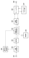
図1は第1の実施形態の画像符号化装置を示すブロック構成図である。画像符号化装置は、以下に説明する構成要素を制御し、装置全体の制御を司る制御部150を有する。この制御部150は、CPU、CPUが実行するプログラムや各種パラメータ等を記憶しているROM、CPUのワークエリアとして使用されるRAMを含む。なお、ROMや他の不揮発性記憶装置に格納されたOS(オペレーティングシステム)、プログラム、パラメータをRAMにロードした後に、OSの制御下でプログラムを実行するようにしてもよい。
[First embodiment]
1 is a block diagram showing an image encoding device according to a first embodiment. The image encoding device has a
また、画像符号化装置は、入力端子101、ブロック分割部102、量子化マトリクス保持部103、予測部104、変換・量子化部105、逆量子化・逆変換部106、画像再生部107、フレームメモリ108、インループフィルタ部109、符号化部110、統合符号化部111、出力端子112、及び、量子化マトリクス符号化部113を有する。
The image coding device also has an
上記構成において、不図示の画像発生源から画像データ(例えば30フレーム/秒)が、本装置の入力端子101に供給される。なお、画像発生源の種類は問わないが、簡単には撮像部もしくはビデオカメラ、或いは、符号化対象の画像データを記憶するハードディスクや記憶媒体である。
In the above configuration, image data (e.g., 30 frames/second) is supplied to the
ブロック分割部102は、入力端子101を介して入力した画像データを複数の基本ブロックに分割し、基本ブロック単位の画像データを後段の予測部104に供給する。
The
量子化マトリクス保持部103は、量子化処理で用いる複数種類の量子化マトリクスを保持している。この量子化マトリクスの生成方法の詳細については後述する。
The quantization
予測部104は、ブロック分割部102からの基本ブロック単位の画像データを入力し、より小さい複数のサブブロックへの分割法を決定し、各サブブロック単位でフレーム内予測であるイントラ予測や、フレーム間予測であるインター予測などを行い、予測画像データを生成する。さらに、予測部104は、サブブロックの画像データと、その予測画像データとの差分である予測誤差データを算出し、供給する。また、予測部104は、予測に必要な情報、例えばサブブロック分割に関する情報、予測モードや動きベクトル等の情報も、予測誤差データと併せて出力する。以下ではこの予測に必要な情報を予測情報と呼称する。
The
変換・量子化部105は、予測部104から供給された予測誤差データをサブブロック単位で直交変換(周波数変換)して変換係数を得る。そして、変換・量子化部105は、着目サブブロックの変換係数を、量子化マトリクス保持部103が保持する該当量子化マトリクスを用いて量子化を行い、量子化係数を得る。
The transform/
逆量子化・逆変換部106は、変換・量子化部105から入力した量子化係数を、量子化マトリクス保持部103が保持する該当量子化マトリクスを用いて逆量子化することいで変換係数を再生し、さらにその変換係数を逆直交変換して予測誤差データを再生する。
The inverse quantization and
画像再生部107は、予測部104から入力した予測情報に基づいて、フレームメモリ108を適宜参照して予測画像データを生成する。そして、画像再生部107は、生成した予測画像データと、逆量子化・逆変換部106からの予測誤差データとから、再生画像データを生成し、再びフレームメモリ108に出力する。
The
インループフィルタ部109は、フレームメモリ108に格納された画像再生部107からの再生画像データに対し、デブロッキングフィルタやサンプルアダプティブオフセットなどのインループフィルタ処理を行い、フィルタ処理後の画像データを、再びフレームメモリ109に格納する。
The in-
符号化部110は、変換・量子化部105から入力した量子化係数および予測部104から入力した予測情報を符号化して、符号データを生成し出力する。
The
量子化マトリクス符号化部113は、量子化マトリクス保持部103から入力した量子化マトリクスを符号化して、量子化の符号化データを生成し出力する。
The quantization
統合符号化部111は、量子化マトリクス符号化部113で符号化された量子化マトリクスの符号化データを用いて、ヘッダ符号データを生成する。さらに統合符号化部111は、生成したヘッダ符号データに、符号化部110から入力した画像の符号データを結合することでビットストリームを形成し、出力端子112を介して外部に出力する。
The integrated
なお、出力先は特に問わないが、記録媒体などの記憶装置や、ネットワーク上のファイルサーバ等で構わない。 The output destination can be anything, including a storage device such as a recording medium or a file server on a network.
以下、実施形態の画像符号化装置における画像の符号化動作を更に詳しく説明する。 The image encoding operation of the image encoding device of the embodiment is described in more detail below.
本実施形態では動画像データをフレーム単位に入力する構成とするが、1フレーム分の静止画像データを入力する構成としても構わない。また、本実施形態では、説明を容易にするため、イントラ予測符号化の処理のみを説明するが、これに限定されずインター予測符号化の処理においても適用可能である。さらに本実施形態では説明のため、ブロック分割部101においては1フレームの画像を分割する基本ブロックのサイズを水平16画素×垂直16画素(以下、単に16×16画素と表記する)として説明するが、これはあくまで例示であり、他のサイズであっても構わない。
In this embodiment, moving image data is input in frame units, but still image data for one frame may also be input. Also, in this embodiment, for ease of explanation, only intra-prediction coding processing is explained, but the present invention is not limited to this and can also be applied to inter-prediction coding processing. Furthermore, in this embodiment, for the sake of explanation, the size of the basic blocks into which one frame of image is divided in the
画像の符号化に先立ち、量子化マトリクスの符号化が行われる。 The quantization matrix is encoded before the image is encoded.
最初に、量子化マトリクス保持部103は、符号化で利用する複数のサイズのサブブロックに応じた、複数の量子化マトリクスを生成し、保持する。図8(a)の参照符号800が示す太枠は、8×8画素のサイズに対応する量子化マトリクスの一例であり、マトリクス内の値はその要素を示している。量子化マトリクス800の左上隅の0行0列の要素がDC成分(直流成分)の変換係数に対応しており、それ以外の要素はAC成分(交流成分)の変換係数にそれぞれ対応している。この量子化マトリクスを構成する各要素の決定方法は特に限定しない。例えば、所定の初期値を用いても良いし、個別に設定しても良い。また、画像の特性に応じて生成されても構わない。
First, the quantization
同様に、量子化マトリクス保持部103は、他のサブブロックのサイズに応じた量子化マトリクスも生成する。図8(b)は、本実施形態における16×8画素の直交変換に対応する量子化マトリクスである。DC成分に対応する0行0列の要素は“4”、その右隣の0行1列の要素は“5”といった個別の値が設定されている。図8(b)の量子化マトリクスの0行1列の要素は、図8(b)の量子化マトリクスに対応するサブブロックの形状において最も低周波であると推定されるAC成分の変換係数に対応する要素である。一方、残りの要素は符号量削減のため、水平方向に隣接する2つの要素に対して1つの値が設定されるような構成となっている。例えば、0行2列および0行3列の要素には“9”という同じ値が設定され、同様に1行2列および1行3列の要素には“10”という同じ値が設定されている。
Similarly, the quantization
図8(c)は、本実施形態における8×16画素の直交変換に対応する量子化マトリクスである。DC成分に対応する0行0列の要素は“4”、その下の1行0列の要素は“5”といった個別の値が設定されている。図8(c)の量子化マトリクスの1行0列の要素は、図8(c)の量子化マトリクスに対応するサブブロックの形状において最も低周波であると推定されるAC成分の変換係数に対応する要素である。一方、残りの要素は符号量削減のため、垂直方向に隣接する2つの要素に対して1つの値が設定されるような構成となっている。例えば、2行0列および3行0列の要素には“9”という同じ値が設定され、同様に2行1列および3行1列の要素には“10”という同じ値が設定されている。
Figure 8(c) is a quantization matrix corresponding to the orthogonal transformation of 8x16 pixels in this embodiment. The element in
図8(d)は、本実施形態における16×16画素の直交変換に対応する量子化マトリクスである。DC成分に対応する0行0列の要素は“4”、その右隣の1行0列および直下の0行1列の要素は“5”、右下の1行1列の要素は“6”といった個別の値がDC成分に隣接したAC成分に対応する要素として設定されている。一方、残りの要素は符号量削減のため、水平及び垂直に隣接する2×2の4つの要素に対して1つの値が設定されるような構成となっている。
Figure 8(d) shows a quantization matrix corresponding to the orthogonal transformation of 16 x 16 pixels in this embodiment. Individual values are set as elements corresponding to the AC components adjacent to the DC component, such as the element at
上記のごとく、量子化マトリクス内のDC成分に対応する要素と、その付近の複数の低周波成分に対応する要素は個別の値を設定し、残りの要素には複数の要素単位で値を設定することで、量子化マトリクスの符号量が削減され易くなり、且つ、人間の視覚が敏感な低周波部分の量子化を細かく制御することができる。 As described above, by setting individual values to the elements in the quantization matrix that correspond to the DC component and the elements that correspond to the multiple low-frequency components nearby, and setting values on a multiple-element basis to the remaining elements, it becomes easier to reduce the amount of code in the quantization matrix, and it is possible to finely control the quantization of the low-frequency parts to which human vision is sensitive.
量子化マトリクス保持部103は、このようにして生成された量子化マトリクスが保持されている。本実施形態では、図8(a)~(d)に示された四種の量子化マトリクスが二次元の形状で保持されているものとするが、量子化マトリクス内の各要素はもちろんこれに限定されない。また、後述の予測方法、例えばイントラ予測を用いるかインター予測を用いるかによって、あるいは符号化対象が輝度ブロックか色差ブロックかによって、同じ大きさの直交変換に対して複数の量子化マトリクスを保持することも可能である。一般的に、人間の視覚特性に応じた量子化処理を実現するため、図8(a)~(d)に示すように量子化マトリクスの左上部分に相当する低周波部分の要素は小さく、右下部分に相当する高周波部分の要素は大きくなっている。
The quantization
量子化マトリクス符号化部113は、二次元形状で格納されている量子化マトリクスを量子化マトリクス保持部106から順に読み出し、各要素を走査して差分を計算し、一次元の行列を生成する。本実施形態では、図8(a)~(d)に示された各量子化マトリクスが符号化されることになる。具体的には、量子化マトリクス符号化部113は、まず図8(a)に示された量子化マトリクスについては、図10(a)に示された矢印に沿った走査方法を用い、要素ごとに走査順に隣り合う要素との差分を計算していく。例えば図8(a)で示された8×8画素分の量子化マトリクスは図10(a)で示された対角線スキャンによって走査されるが、左上隅に位置する最初の要素“4”の次はそのすぐ下に位置する要素“9”が走査され、差分である+5が計算される。また、量子化マトリクスの最初の要素(本実施形態では“4”)の符号化には、所定の初期値(例えば“8”)との差分を計算するものとするが、もちろんこれに限定されず、任意の値との差分や、最初の要素の値そのものを用いても良い。
The quantization
同様に、量子化マトリクス符号化部113は、図8(b)に示された量子化マトリクスについては、図10(b)に示される矢印に沿った走査方法を用い、要素ごとに走査順に直前の要素との差分を計算するものとする。例えば図8(b)に示された16×8画素分の量子化マトリクスは図10(b)に示された走査方法によって走査されるが、左上端に位置する最初の要素「4」の次はそのすぐ右に位置する要素「5」が走査され、差分である+1が符号化される。次にその下に位置する要素「9」が走査され、差分である+4が符号化される。
Similarly, for the quantization matrix shown in Fig. 8(b), the quantization
図8(c)においても同様であり、図8(c)に示された8×16画素分の量子化マトリクスは図10(c)に示された走査方法によって走査される。左上端に位置する最初の要素「4」の次はそのすぐ下に位置する要素「5」が走査され、差分である+1が符号化される。そしてその下に位置する要素「9」が走査され、差分である+4が符号化される。 The same is true for Figure 8(c), where the 8x16 pixel quantization matrix shown in Figure 8(c) is scanned using the scanning method shown in Figure 10(c). After the first element "4" located at the top left corner, the element "5" located immediately below it is scanned, and the difference of +1 is encoded. Then the element "9" located below that is scanned, and the difference of +4 is encoded.
図8(d)に示された16×16画素分の量子化マトリクスにおいては、図10(d)に示された走査方法によって走査される。左上端に位置する最初の要素4の次は、そのすぐ下に位置する要素5が走査され、差分である+1が符号化される。次に左上端の右隣に位置する要素5が走査され、差分である0が符号化される。そして、その下に位置する要素6が走査され、差分である+1が符号化される。
The 16x16 pixel quantization matrix shown in Figure 8(d) is scanned using the scanning method shown in Figure 10(d). After the
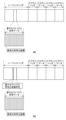
このようにして、本実施形態では、図8(a)~(d)の量子化マトリクスは、それぞれ図10(a)~(d)の走査方法を用い、図11(a)~(d)に示される一次元の差分行列が生成される。量子化マトリクス符号化部113はさらに前記差分行列を符号化して量子化マトリクス符号データを生成する。本実施形態では図12(a)に示される符号化テーブルを用いて符号化するものとするが、符号化テーブルはこれに限定されず、例えば図12(b)に示される符号化テーブルを用いても良い。このようにして生成された量子化マトリクス符号データは後段の統合符号化部111に供給される。
In this way, in this embodiment, the quantization matrices in Figures 8(a) to (d) are generated using the scanning methods in Figures 10(a) to (d), respectively, to generate one-dimensional difference matrices as shown in Figures 11(a) to (d). The quantization
図1に戻り、統合符号化部111は、画像データの符号化に必要なヘッダ情報を符号化し、量子化マトリクスの符号データを統合する。続いて、画像データの符号化を説明する。
Returning to FIG. 1, the
ブロック分割部102は、入力端子101から入力された1フレーム分の画像データを、複数の基本ブロックに分割し、基本ブロック単位の画像データを予測部104に供給する。先に説明したように本実施形態での基本ブロックのサイズは16×16画素である。
The
予測部104は、ブロック分割部102から入力された基本ブロック単位の画像データに対し予測処理を実行する。具体的には、予測部104は、基本ブロックをさらに細かいサブブロックに分割するサブブロック分割法を決定し、さらにサブブロック単位で水平予測や垂直予測などのイントラ予測モードを決定する。なお、サブブロック分割法は、直前のフレームの符号化データ量等から決定するものとする。
The
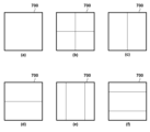
図7(a)乃至(d)はサブブロック分割パターンの例を示している。同図の外側の太枠を示す参照符号700が基本ブロックを表しており、実施形態の場合は16×16画素のサイズである。そして、太枠内の矩形がサブブロックを表している。図7(b)は従来の正方形サブブロック分割の一例を表しており、16×16画素の基本ブロックは、8×8画素サイズの4つのサブブロックに分割されている。一方、図7(c)、(d)は長方形サブブロック分割の一例を表しており、図7(c)では基本ブロックが8×16画素の縦長の2つのサブブロックに、図7(d)では16×8画素の横長の2つのサブブロックに分割されている。
Figures 7(a) to (d) show examples of subblock division patterns. The
本実施形態では、16×16画素の基本ブロックを、分割しない(図7(a))、垂直方向に長手の2つのサブブロックに分割する(図7(c))、水平方向に長手の2つのサブブロックに分割する(図7(d))、及び、四分木分割する(図7(b))のいずれかが決定されるものとする。ただし、サブブロック分割方法はこれに限定されない。図7(e)、(f)のように1:2:1の比で分割する三分木分割を用いても構わない。 In this embodiment, it is decided whether a basic block of 16x16 pixels is not divided (Fig. 7(a)), is divided into two sub-blocks in the vertical direction (Fig. 7(c)), is divided into two sub-blocks in the horizontal direction (Fig. 7(d)), or is divided using a quadtree method (Fig. 7(b)). However, the sub-block division method is not limited to this. Ternary tree division that divides in a ratio of 1:2:1 as shown in Figs. 7(e) and (f) may also be used.
決定したイントラ予測モードおよび符号化済の画素から予測画像データが生成される。そして、予測部104は、サブブロック単位に、入力された画像データと、生成した予測画像データとの差分である予測誤差データを生成し、その予測誤差データを変換・量子化部105に供給する。また、サブブロック分割やイントラ予測モードなどの情報は予測情報として、符号化部110、画像再生部107に供給される。
Prediction image data is generated from the determined intra prediction mode and the encoded pixels. The
変換・量子化部105では、入力された予測誤差データに対して直交変換・量子化を行い、量子化係数を生成する。具体的には、変換・量子化部105は、まず、サブブロックのサイズに対応した直交変換処理を施し、直交変換係数を生成する。そして、変換・量子化部105は、サブブロック単位に、直交変換係数を量子化マトリクス保持部103に格納されている、対応するサイズの量子化マトリクスを用いて量子化し、量子化係数を生成する。本実施形態では、図7(a)に対応した16×16画素のサブブロック分割に対しては図8(d)の量子化マトリクスが用いられるものとする。同様にして、図7(c)の8×16画素のサブブロック分割に対しては図8(c)、図7(d)の16×8のサブブロック分割に対しては図8(b)の量子化マトリクスが用いられるものとする。また、図7(b)に示す、垂直、水平とも基本ブロックの1/2のサイズのサブブロック分割(四分木分割)には、図8(a)で示される量子化マトリクスが用いられるものとする。変換・量子化部105は、生成された量子化係数(量子化後の変換係数)を符号化部110および逆量子化・逆変換部106に供給する。
The transform/
逆量子化・逆変換部106は、サブブロック単位に、入力された量子化係数を、量子化マトリクス保持部103に格納されている、対応する量子化マトリクスを用いて逆量子化することで、変換係数を再生する。そして、逆量子化・逆変換部106は、サブブロック単位に、再生された変換係数を逆直交変換して予測誤差データを再生し、再生された予測誤差データを画像再生部107に供給する。
The inverse quantization and
画像再生部107は、サブブロック単位に、予測部104から入力される予測情報に基づいて、フレームメモリ108を適宜参照し、予測画像データを再生する。画像再生部107は、サブブロック単位に、再生された予測画像データと、逆量子化・逆変換部106から入力した予測誤差データとを加算することで、サブブロックの画像データを再生し、再生した画像データをフレームメモリ108に格納する。
The
インループフィルタ部109は、サブブロック単位に、フレームメモリ108から再生画像データを読み出し、デブロッキングフィルタなどのインループフィルタ処理を行う。そして、インループフィルタ部109は、フィルタ処理された画像データをフレームメモリ108に再格納する。
The in-
符号化部110は、サブブロック単位に、変換・量子化部105で生成された量子化係数、予測部104から入力された予測情報をエントロピー符号化し、符号データを生成する。エントロピー符号化の方法は特に問わないが、ゴロム符号化、算術符号化、ハフマン符号化などを用いることができる。生成された符号データは統合符号化部111に供給される。
The
統合符号化部111では、前述のヘッダの符号データとともに符号化部110から入力された符号データなどを多重化してビットストリームを形成する。最終的には、ビットストリームは端子112から外部に出力される。
The
図6(a)は第1の実施形態で出力されるビットストリームのデータ構造例を示している。シーケンスヘッダに図8(a)~(d)の各量子化マトリクスに対応する符号データが含まれ、各要素の符号化結果で構成されている。ただし、符号化される位置はこれに限定されず、ピクチャヘッダ部やその他のヘッダ部に符号化される構成をとってももちろん構わない。また、1つのシーケンスの中で量子化マトリクスの変更を行う場合、量子化マトリクスを新たに符号化することで更新することも可能である。この際、全ての量子化マトリクスを書き換えても良いし、書き換える量子化マトリクスの変換ブロックサイズを指定することでその一部を変更するようにすることも可能である。 Figure 6 (a) shows an example of the data structure of a bitstream output in the first embodiment. The sequence header contains code data corresponding to each of the quantization matrices in Figures 8 (a) to (d), and is composed of the encoding results of each element. However, the position at which the data is encoded is not limited to this, and it is of course possible to have the data encoded in the picture header section or other header section. In addition, when changing the quantization matrix within a single sequence, it is also possible to update the quantization matrix by newly encoding it. In this case, all quantization matrices may be rewritten, or it is also possible to change only a part of the quantization matrix by specifying the transform block size of the quantization matrix to be rewritten.
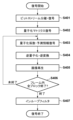
以下、第1の実施形態に係る画像符号化装置における1フレームの符号化処理の処理手順を図3のフローチャートを参照して説明する。なお、以下の説明における各工程は、その主体が制御部150による制御下にてそれぞれの処理を実行するものとする。
The procedure for encoding one frame in the image encoding device according to the first embodiment will be described below with reference to the flowchart in FIG. 3. Note that each step in the following description is performed under the control of the
まず、画像の符号化に先立ち、S301にて、量子化マトリクス保持部103は、量子化マトリクスを生成し、保持する。本実施形態では、量子化マトリクス保持部103は図8(a)~(d)に示された4種類の量子化マトリクスを生成し、保持するものとする。
First, prior to encoding an image, in S301, the quantization
S302にて、量子化マトリクス符号化部113は、S301にて生成・保持された量子化マトリクスを走査して各要素の差分を算出し、1次元の差分行列を生成する。本実施形態では、量子化マトリクス符号化部113は、図8(a)~(d)の量子化マトリクスを、図10(a)~(d)の走査順に沿って、連続する2つの要素の差分値を求めていき、図11(a)~(d)に示される差分値の1次元行列を生成する。そして、量子化マトリクス符号化部113は、生成された行列における個々の差分値を、図12(a)(又は図12(b))に示す符号化テーブルを参照して二進符号を生成し、符号化データを生成していく。
In S302, the quantization
S303にて、統合符号化部111は、生成された量子化マトリクス符号データとともに、画像データの符号化に必要なヘッダ情報を生成し、出力する。
At S303, the
S304にて、ブロック分割部102は、フレーム単位の入力画像を基本ブロック単位に分割する。そして、S305にて、予測部104は、S304にて生成された1つの基本ブロックの画像データを入力し、サブブロックへの変換を行う。そして、予測部104は、各サブブロックについての予測処理を実行し、サブブロック分割情報やイントラ予測モードなどの予測情報および予測画像データを生成する。そして、予測部104は、各サブブロックの画像データとその予測画像データから予測誤差データを算出する。
At S304, the
S306にて、変換・量子化部105は、S305で算出された各サブブロックの予測誤差データそれぞれを直交変換して変換係数を生成する。更に、変換・量子化部105は、S301にて生成・保持された量子化マトリクスを用いて、各サブブロックの予測誤差データを量子化し、量子化係数を生成する。本実施形態では、図7(a)に対応したサブブロック分割に対しては図8(d)の量子化マトリクスが用いられるものとする。同様にして、図7(c)のサブブロック分割に対しては図8(c)、図7(d)のサブブロック分割に対しては図8(b)の量子化マトリクスが用いられるものとする。さらに、図7(b)のように四分木分割されたサブブロックに対しては図8(a)に示される量子化マトリクスが用いられるものとする。
In S306, the transform/
S307にて、逆量子化・逆変換部106は、S305で生成された各サブブロックの量子化係数を、S301にて生成・保持された量子化マトリクスを用いて逆量子化を行い、変換係数を再生する。そして、逆量子化・逆変換部106は、さらに、各サブブロックの変換係数に対して逆直交変換し、サブブロック毎の予測誤差データを再生する。
In S307, the inverse quantization and
S308にて、画像再生部107は、S305で生成された予測情報に基づいて、サブブロックごとの予測画像データを再生する。画像再生部107は、さらに再生された各サブブロックの予測画像データに、S307で生成された対応するサブブロックの予測誤差データを加算することで、サブブロック毎の画像データを再生する。
In S308, the
S309にて、符号化部110は、サブブロックごとに、S305で生成された予測情報、および、S306で生成された量子化係数を符号化し、符号データを生成する。また、他の符号データも含め、ビットストリームを生成する。
In S309, the
S310にて、制御部150は、フレーム内の全ての基本ブロックの符号化が終了したか否かの判定を行い、終了していればS311に進み、そうでなければ次の基本ブロックを対象とする符号化を行うため、処理をS305に戻す。
At S310, the
S311にて、インループフィルタ部109は、S308で再生された画像データに対し、インループフィルタ処理を行い、フィルタ処理された画像を生成し、処理を終了する。
At S311, the in-
上記の処理において、動画像の2つ目以降のフレームの符号化を行う場合には、S304乃至S311を、符号化すべき最後のフレームの入力まで繰り返すことになる。 In the above process, when encoding the second or subsequent frames of a video, steps S304 to S311 are repeated until the last frame to be encoded is input.
以上の構成と動作により、特にS302において量子化マトリクスの初め所定数の要素(DC成分用の要素及びそれに隣接する比較的低周波成分用の要素)については個別に符号化し、残りの要素を複数の要素単位で符号化することで、量子化マトリクスの符号量を削減することができる。さらに、人間の視覚が敏感な低周波部分の量子化を細かく制御することもできる。 With the above configuration and operation, particularly in S302, the first predetermined number of elements of the quantization matrix (the element for the DC component and the adjacent element for the relatively low frequency component) are coded individually, and the remaining elements are coded in units of multiple elements, thereby reducing the amount of code in the quantization matrix. Furthermore, it is also possible to finely control the quantization of the low frequency portion to which human vision is sensitive.
なお、本実施形態では、図8(a)~(d)の4種類の量子化マトリクス全てを符号化する構成としたが、4種類の量子化マトリクスを独立して符号化する代わりに、復号側の装置において、他の量子化マトリクスを用いて当該量子化マトリクスを生成する構成としても構わない。例えば、16×8の量子化マトリクス自体を符号化せずに、符号化された16×16の量子化マトリクスを用いて生成する構成とした場合、復号側の装置において、図8(d)の量子化マトリクスから一部の要素を間引き図8(b)の量子化マトリクスを生成することとなる。同様に、復号側の装置において、図8(d)の量子化マトリクスから一部の要素を間引いて図8(c)の量子化マトリクスを生成することも可能である。また、図8(b)の0行1列の要素「5」や図8(c)の1行0列の要素「5」の算出方法を符号化側および復号側の装置間において定めておけば、図8(a)の量子化マトリクスを用いて図8(b)や図8(c)の量子化マトリクスを生成することも可能である。この場合の算出方法は特に限定されず、0行0列の要素「4」に特定の差分値(本実施形態では+1)を加算して算出しても良いし、周辺の要素との補間を用いて算出しても良い。なお、図8(c)については、変換係数のDC成分に対応する要素の右側および下側の要素については、DC成分に対応する要素に+1を加え、右下の要素については+2を加えている。
In this embodiment, all four types of quantization matrices shown in Fig. 8(a) to (d) are coded, but instead of coding the four types of quantization matrices independently, the decoding device may generate the quantization matrix using another quantization matrix. For example, if the 16x8 quantization matrix is not coded itself but is generated using the coded 16x16 quantization matrix, the decoding device will thin out some elements from the quantization matrix shown in Fig. 8(d) to generate the quantization matrix shown in Fig. 8(b). Similarly, the decoding device can thin out some elements from the quantization matrix shown in Fig. 8(d) to generate the quantization matrix shown in Fig. 8(c). Also, if the method of calculating the element "5" in
また、16×16の量子化マトリクスの要素とともに、図8(b)の0行1列の要素「5」や図8(c)の1行0列の要素「5」自体を符号化してもよい。
In addition to the elements of the 16x16 quantization matrix, the element "5" in
これにより、量子化マトリクスの符号量をさらに削減したビットストリームを符号化することができる。 This makes it possible to encode a bitstream with even less coding space for the quantization matrix.
さらには、量子化マトリクスごとに別の量子化マトリクスから生成するか、各要素を符号化するかを選択し、識別子をヘッダ内に符号化する構成としても構わない。例えば、量子化マトリクスの各要素を他の量子化マトリクスから生成するか、個別に符号化するかを示す情報を、量子化マトリクス符号化方法情報符号としてヘッダ部分に符号化し、図6(b)に示されるビットストリームを生成する構成としても良い。これにより、サブブロックの大きさに応じた画質制御を優先したビットストリームか、量子化マトリクスの符号量がより少ないビットストリームかを選択的に生成することができる。 Furthermore, it is also possible to select whether each quantization matrix is generated from a different quantization matrix or each element is encoded, and to encode the identifier in the header. For example, information indicating whether each element of the quantization matrix is generated from another quantization matrix or encoded individually may be encoded in the header as a quantization matrix encoding method information code, and a bitstream as shown in FIG. 6(b) may be generated. This makes it possible to selectively generate a bitstream that prioritizes image quality control according to the size of the subblock, or a bitstream with a smaller amount of quantization matrix encoding.
また本実施形態では、図7(a)~図7(d)のサブブロック分割・直交変換に対応する図8(a)~図8(d)の量子化マトリクスが用いられる構成としたが、使用される直交変換サイズや量子化マトリクスはこれに限定されない。例えば、図7(e)、(f)のように1:2:1の比で分割する三分木分割がさらに用いられた場合、図9(a)、(b)の量子化マトリクスをさらに用いる構成としても構わない。 In addition, in this embodiment, the quantization matrices in Figs. 8(a) to 8(d) corresponding to the subblock division and orthogonal transform in Figs. 7(a) to 7(d) are used, but the orthogonal transform size and quantization matrices used are not limited to this. For example, if ternary tree division that divides at a ratio of 1:2:1 as in Figs. 7(e) and (f) is also used, the quantization matrices in Figs. 9(a) and (b) may also be used.
以上の説明したように、実施形態における量子化マトリクス保持部103は、基本ブロック(実施形態では16×16のサイズ)の水平、垂直方向のいずれかの一方のみが同じサイズを有し、他方が異なる図8(b)、(c)に示すような量子化マトリクスの長辺方向については、直流成分に対応する要素の格納位置から予め設定された所定範囲(実施形態では距離“1”の範囲)では、各変換係数に対応する位置毎の要素を独立して保持し、長辺方向における所定範囲を超える位置では、変換係数の予め設定された個数単位(実施形態では2個)に同じ要素を保持する。一方、図8(b)、(c)に示すような量子化マトリクスの短辺方向については、変換係数ごとに量子化マトリクスの要素が配置される。
As described above, the quantization
そして、水平、垂直方向のいずれも基本ブロックのサイズと同じサイズである量子化マトリクスについては、図8に示すように、直流成分に対応する要素の位置およびその位置に対して、右、下、右下に隣接する4つの要素(実施形態では距離“1”の範囲)を対応する変換係数ごとに個別に保持する。そして、それ以外の変換係数ついては、互いに隣接する4つの変換係数ごとに1つの同じ要素を保持する。そして、図8(a)に示すような8x8のサイズの量子化マトリクスの場合、変換係数ごとに要素を保持することになる。 For a quantization matrix that is the same size as the basic block in both the horizontal and vertical directions, as shown in Figure 8, the position of the element corresponding to the DC component and the four elements adjacent to the right, below, and to the lower right of that position (in this embodiment, a distance of "1" is used) are stored separately for each corresponding transform coefficient. For the other transform coefficients, one identical element is stored for every four mutually adjacent transform coefficients. For a quantization matrix of 8x8 size as shown in Figure 8(a), an element is stored for each transform coefficient.
このように量子化マトリクスのサイズに従って、変換係数に対する要素の割り当てを適応的に変えているため、量子化マトリクスの符号量を抑制でき、且つ、画質劣化を抑制できるようになる。 In this way, the allocation of elements to transform coefficients is adaptively changed according to the size of the quantization matrix, making it possible to reduce the amount of code in the quantization matrix and also to suppress degradation in image quality.
なお、量子化マトリクスの要素を符号化する際の図10に示すような走査順に基づいて「所定範囲」を定義してもよい。8x16あるいは16x8の変換係数のブロックサイズブロックサイズついては、図10(b)(c)の走査が量子化マトリクスの要素の符号化/復号のために行われることになる。この際、以降に記載される復号装置の処理において、変換係数のDC成分に対応する要素から1走査(距離“1”の範囲)して得られる要素を変換係数ごとに割り当てを行い、それ以降は2つの変換係数ごとに1つの要素が割り当てられることになる。すなわち、図8(b)(c)に示すような量子化マトリクスが復号装置の処理において得られることになる。また、16x16の変換係数のブロックサイズの場合、変換係数のDC成分に対応する要素から3走査(距離“3”の範囲)して得られる要素を変換係数ごとに割り当てを行い、それ以降は4つの変換係数ごとに1つの要素が割り当てられることになる。すなわち、図8(d)に示すような量子化マトリクスが得られることになる。また、8x8の変換係数のブロックサイズの場合、変換係数のDC成分に対応する要素から全ての走査によって得られる要素が変換係数ごとに割り当てられることになる。すなわち、図8(a)に示すような量子化マトリクスが復号装置の処理において得られることになる。このように、量子化マトリクスに対する走査に基づいて、量子化マトリクスのサイズついて適応的に変換係数に対する要素の割り当てを変えてもよい。この場合、要素間の位置関係を特別に考慮する必要がなくなる。 The "predetermined range" may be defined based on the scanning order shown in FIG. 10 when encoding elements of a quantization matrix. For block sizes of 8x16 or 16x8 transform coefficients, the scanning shown in FIG. 10(b) and (c) is performed to encode/decode elements of a quantization matrix. In this case, in the process of the decoding device described below, elements obtained by one scan (within the distance "1") from the element corresponding to the DC component of the transform coefficient are assigned to each transform coefficient, and one element is assigned to every two transform coefficients thereafter. That is, the quantization matrix shown in FIG. 8(b) and (c) is obtained in the process of the decoding device. In addition, in the case of a block size of 16x16 transform coefficients, elements obtained by three scans (within the distance "3") from the element corresponding to the DC component of the transform coefficient are assigned to each transform coefficient, and one element is assigned to every four transform coefficients thereafter. That is, the quantization matrix shown in FIG. 8(d) is obtained. Furthermore, in the case of a block size of 8x8 transform coefficients, elements obtained by all scans from the element corresponding to the DC component of the transform coefficient are assigned to each transform coefficient. That is, a quantization matrix such as that shown in FIG. 8(a) is obtained in the processing of the decoding device. In this way, the assignment of elements to transform coefficients may be adaptively changed for the size of the quantization matrix based on the scan of the quantization matrix. In this case, there is no need to take into special consideration the positional relationship between elements.
[第2の実施形態]
第2の実施形態では、上記第1の実施形態の画像符号化装置で生成された符号化データを復号する画像復号装置を説明する。図2は、その画像復号装置のブロック構成図である。
Second Embodiment
In the second embodiment, an image decoding device that decodes encoded data generated by the image encoding device of the first embodiment will be described. Fig. 2 is a block diagram showing the configuration of the image decoding device.
画像復号装置は、以下に説明する構成要素を制御し、装置全体の制御を司る制御部250を有する。この制御部250は、CPU、CPUが実行するプログラムや各種パラメータ等を記憶しているROM、CPUのワークエリアとして使用されるRAMを含む。なお、ROMや他の不揮発性記憶装置に格納されたOS(オペレーティングシステム)、プログラム、パラメータをRAMにロードした後に、OSの制御下でプログラムを実行するようにしてもよい。
The image decoding device has a
また、画像復号装置は、入力端子201、分離復号部202、復号部203、逆量子化・逆変換部204、画像再生部205、フレームメモリ206、インループフィルタ部207、出力端子208、及び、量子化マトリクス復号部209を有する。
The image decoding device also has an
上記画像復号装置の構成における画像復号装置の構成とその動作を以下に説明する。なお、画像復号装置は、先に説明した画像符号化装置が生成したビットストリームをフレーム単位で入力する構成となっているが、1フレーム分の静止画像ビットストリームを入力する構成としても構わない。また、本第2の実施形態では説明を容易にするため、イントラ予測復号処理のみを説明するが、これに限定されずインター予測復号処理においても適用可能である。 The configuration and operation of the image decoding device in the above-mentioned image decoding device configuration will be described below. Note that the image decoding device is configured to input the bit stream generated by the image encoding device described above on a frame-by-frame basis, but it may also be configured to input a still image bit stream for one frame. Also, in this second embodiment, for ease of explanation, only intra-prediction decoding processing will be described, but the present invention is not limited to this and can also be applied to inter-prediction decoding processing.
分離復号部202は、入力端子201を介して符号化ビットストリームを入力し、ビットストリームから復号処理に関する情報や係数に関する符号データに分離し、またビットストリームのヘッダ部に存在する符号データを復号する。本実施形態の分離復号部202は、符号化ビットストリームから量子化マトリクスの符号化データを分離し、その符号化データを量子化マトリクス復号部209に供給する。また、分離復号部202は、符号化ビットストリームから画像データの符号化データを分離し、復号部203に供給する。要するに、分離復号部202は、図1の統合符号化部111と逆の動作を行う。
The
量子化マトリクス復号部209は、分離復号部202から供給された量子化マトリクスの符号化データを復号し、量子化マトリクスを再生、保持する。
The quantization
復号部203は、分離復号部202から入力した画像データの符号データを復号し、量子化係数および予測情報を再生する。
The
逆量子化・逆変換部204は、図1の逆量子化・逆変換部106と同様、再生された量子化マトリクスを用いて量子化係数に逆量子化を行って変換係数を得、さらに逆直交変換を行い、予測誤差データを再生する。
The inverse quantization and
画像再生部205は、入力された予測情報に基づいてフレームメモリ206を適宜参照して予測画像データを生成する。そして、画像再生部205は、この予測画像データに、逆量子化・逆変換部204で再生された予測誤差データを加算することで、画像データを再生し、フレームメモリ206に格納する。
The
インループフィルタ部207は、図1のインループフィルタ部109と同様、フレームメモリ207に格納された再生画像データに対し、デブロッキングフィルタなどのインループフィルタ処理を行い、フィルタ処理された画像データをフレームメモリに再格納する。そして、出力端子208は、再生された画像データを外部装置(例えば表示装置)に出力する。
The in-
次に、図2の画像復号装置における各構成要素の動作を更に詳しく説明する。 Next, we will explain in more detail the operation of each component in the image decoding device shown in Figure 2.
本第2の実施形態では、第1の実施形態で生成されたビットストリームをフレーム単位で入力する構成となっているが、1フレーム分の静止画像ビットストリームを入力する構成としても構わない。また、本実施形態では説明を容易にするため、イントラ予測復号処理のみを説明するが、これに限定されずインター予測復号処理においても適用可能である。 In the second embodiment, the bit stream generated in the first embodiment is input on a frame-by-frame basis, but a still image bit stream for one frame may also be input. In addition, in this embodiment, for ease of explanation, only intra-prediction decoding processing is explained, but the present invention is not limited to this and can also be applied to inter-prediction decoding processing.
入力端子201を介して入力された1フレーム分のビットストリームは分離復号部202に供給される。分離復号部202は、ビットストリームから復号処理に関する情報や係数に関する符号データに分離し、ビットストリームのヘッダ部に存在する符号データを復号する。より具体的には、分離復号部202は、量子化マトリクスの符号データを再生する。本実施形態の分離復号部202は、まず、図6(a)に示されるビットストリームのシーケンスヘッダから量子化マトリクスの符号データを抽出し、量子化マトリクス復号部209に供給する。分離復号部202は、続いて、ピクチャデータの基本ブロックのサブブロック単位の符号データを再生し、復号部203に供給する。
The bit stream for one frame input via the
量子化マトリクス復号部209は、まず入力された量子化マトリクスの符号データを復号し、一次元の差分行列を再生する。本実施形態では、第1の実施形態と同様、図12(a)(又は同図(b))に示される符号化テーブルを用いて復号するものとするが、符号化テーブルはこれに限定されず、第1の実施形態と同じものを用いる限りは他の符号化テーブルを用いても良い。さらに量子化マトリクス復号部209は、再生された一次元の差分行列を逆走査し、二次元の量子化マトリクスを再生する。ここでは第1の実施形態の量子化マトリクス符号化部113の走査とは逆の動作を行う。すなわち、本実施形態の量子化マトリクス復号部209は、図11(a)~(d)に示される差分行列はそれぞれ、図10(a)~(d)に示される走査方法を用いて、図8(a)~(d)に示される量子化マトリクスを再生し、保持する。
The quantization
本実施形態での具体的な量子化マトリクスの復号処理を、図8(b)の16×8の量子化マトリクスの復号処理を例にとって説明する。量子化マトリクス復号部209は、図11(b)に示された差分行列は図10(b)に示される走査方法を用いて、図8(b)に示される量子化マトリクスを再生する。量子化マトリクス復号部209は、初期値である“8”と、図11(b)の最初の差分値“-4”から、最初の要素である「4」を算出し、図10(b)の最初の走査位置である0行0列の位置の要素の値“4”を決定し、図8(b)の0行0列の部分に要素“4”を配置する。次に、量子化マトリクス復号部209は、図8(b)の0行0列の要素“4”と、図11(b)の二番目の差分値“1”から二番目の要素である“5”を算出し、図10(b)の2番目の走査位置である0行1列の部分に“5”を配置する。同様にして、図8(b)の0行1列の要素“5”と図10(b)の三番目の差分値“4”から三番目の要素である“9”を算出し、図9(b)の3番目の走査位置である1行0列および1行1列の部分に“9”を配置する。同様の処理を繰り返し、図8(b)に示される量子化マトリクスを再生する。
A specific quantization matrix decoding process in this embodiment will be described using the decoding process of the 16x8 quantization matrix in FIG. 8(b) as an example. The quantization
こうして、量子化マトリクスの低周波成分に対応する複数の要素に個別の値を配置し、残りの要素には複数の要素単位で値を配置することで、符号量を削減しつつ、人間の視覚が敏感な低周波部分の量子化を細かく制御したビットストリームを復号することができる。 In this way, by assigning individual values to multiple elements corresponding to the low-frequency components of the quantization matrix and assigning values to the remaining elements in multiple element units, it is possible to reduce the amount of code while decoding a bitstream with finely controlled quantization of the low-frequency parts to which human vision is sensitive.
図2に戻り、復号部203は、基本ブロック内の各サブブロックの符号データを復号し、量子化係数および予測情報を再生する。復号部203は、再生された量子化係数を逆量子化・逆変換部204に、再生された予測情報を画像再生部205にそれぞれ供給する。
Returning to FIG. 2, the
逆量子化・逆変換部204は、サブブロック単位に、入力した量子化係数に対し、量子化マトリクス復号部209で再生、保持している量子化マトリクスを用いて逆量子化を行い、直交変換係数を生成する。逆量子化・逆変換部204は更に、サブブロック単位に、生成した直交変換係数に対して逆直交変換を施して予測誤差データを再生し、画像再生部205に供給する。この際、復号対象のサブブロックの大きさに応じて用いられる量子化マトリクスが定まり、本実施形態では、図7(a)に対応したサブブロック分割に対しては図8(d)の量子化マトリクスが用いられるものとする。同様にして、図7(c)のサブブロック分割に対しては図8(c)、図7(d)のサブブロック分割に対しては図8(b)の量子化マトリクスが用いられるものとする。また、図7(b)の四分木のサブブロック分割には図8(a)で示される量子化マトリクスが用いられるものとする。
The inverse quantization and
画像再生部205は、サブブロック単位に、復号部203から入力した予測情報に基づいて、フレームメモリ206を適宜参照し、予測画像データを再生する。そして、画像再生部205は、この予測画像データに、逆量子化・逆変換部204から供給された予測誤差データを加算することで、サブブロックの画像データを再生し、フレームメモリ206に格納する。このフレームメモリ206に格納された画像データは、他のサブブロックを復号する際の予測参照候補となる。
The
インループフィルタ部207は、図1のインループフィルタ部109と同様、サブブロック単位に、フレームメモリ206から再生画像データを読み出し、デブロッキングフィルタなどのインループフィルタ処理を行う。そして、インループフィルタ部207は、フィルタ処理された画像は再びフレームメモリ206に格納する。
The in-
フレームメモリ206に格納された再生画像は、最終的には端子208から外部に出力される。
The reproduced image stored in the
以下、第2の実施形態に係る画像復号装置における1フレームの復号処理の処理手順を図4のフローチャートを参照して説明する。なお、以下の説明における各工程は、その主体が制御部250による制御下にて、それぞれの処理を実行するものとする。
The processing procedure for decoding one frame in the image decoding device according to the second embodiment will be described below with reference to the flowchart in FIG. 4. Note that each step in the following description is performed under the control of the
まず、S401にて、分離復号部202は、ビットストリームから復号処理に関する情報や係数に関する符号データに分離して、ヘッダ部分の符号データを復号する。より具体的には、量子化マトリクスを符号データを再生する。
First, in S401, the separation/
S402にて、量子化マトリクス復号部209は、S401で再生された量子化マトリクスの符号データを復号し、図10で示されたような一次元の差分行列を再生する。さらに量子化マトリクス復号部209は、再生された一次元の差分行列を逆走査し、二次元の量子化マトリクスを再生する。すなわち、量子化マトリクス復号部209は、図11(a)~(d)に示される差分行列をそれぞれ、図10(a)~(d)に示される走査方法を用いて、図8(a)~(d)に示される量子化マトリクスを再生し、保持する。なお、図10(a)~(d)に示される走査方法および量子化マトリクスの要素の変換係数に対する割り当ては復号側装置において既知のものとする。すなわち、変換係数のDC成分に対応する要素からの距離に従って、量子化マトリクスの各要素が変換係数に割り当てられる。
すなわち、基本ブロック(実施形態では16×16のサイズ)の水平、垂直方向のいずれかの一方のみが同じサイズを有し、他方が異なる図8(b)、(c)に示すような量子化マトリクスの長辺方向については、直流成分に対応する要素の格納位置から予め設定された所定範囲(実施形態では距離“1” の範囲)では、量子化マトリクス復号部209は、各変換係数に対応する位置毎に要素1つの要素を割り当て、長辺方向における所定範囲を超える位置では、変換係数の予め設定された個数単位(実施形態では2個)に同じ要素を割り当てる。一方、図8(b)、(c)に示すような量子化マトリクスの短辺方向については、変換係数ごとに量子化マトリクスの要素を割り当てる。
In S402, the quantization
That is, in the long side direction of the quantization matrix as shown in Figures 8(b) and (c), where only one of the horizontal and vertical directions of a basic block (16x16 in this embodiment) has the same size and the other is different, within a predetermined range (a distance of "1" in this embodiment) from the storage position of the element corresponding to the DC component, the quantization
そして、水平、垂直方向のいずれも基本ブロックのサイズと同じサイズである量子化マトリクスについては、量子化マトリクス復号部209は、図8に示すように、直流成分に対応する要素の位置およびその位置に対して、右、下、右下に隣接する4つの要素(実施形態では距離“1” の範囲)を対応する変換係数ごとに個別に割り当てる。そして、それ以外の変換係数ついては、互いに隣接する4つの変換係数ごとに1つの同じ要素を割り当てる。そして、図8(a)に示すような8x8のサイズの量子化マトリクスの場合、変換係数ごとに要素を保持することになる。
For a quantization matrix that is the same size as the basic block in both the horizontal and vertical directions, the quantization
このように量子化マトリクスのサイズに従って、変換係数に対する要素の割り当てを適応的に変えているため、量子化マトリクスの符号量を抑制でき、且つ、画質劣化を抑制できるようになる。 In this way, the allocation of elements to transform coefficients is adaptively changed according to the size of the quantization matrix, making it possible to reduce the amount of code in the quantization matrix and also to suppress degradation in image quality.
なお、量子化マトリクスの要素を復号する際の図10に示すような走査順に基づいて「所定範囲」を定義してもよい。8x16あるいは16x8の変換係数のブロックサイズブロックサイズついては、図10(b)(c)の走査が量子化マトリクスの要素の復号のために行われることになる。この際、量子化マトリクス復号部209は、変換係数のDC成分に対応する要素から1走査(距離“1”の範囲)して得られる要素を変換係数ごとに割り当てを行い、それ以降は2つの変換係数ごとに1つの要素を割り当てる。すなわち、図8(b)(c)に示すような量子化マトリクスが得られることになる。また、16x16の変換係数のブロックサイズの場合、量子化マトリクス復号部209は、変換係数のDC成分に対応する要素から3走査(距離“3”の範囲)して得られる要素を変換係数ごとに割り当てを行い、それ以降は4つの変換係数ごとに1つの要素を割り当てる。すなわち、図8(d)に示すような量子化マトリクスが得られることになる。また、8x8の変換係数のブロックサイズの場合、量子化マトリクス復号部209は、変換係数のDC成分に対応する要素から全ての走査によって得られる要素を変換係数ごとにる。すなわち、図8(a)に示すような量子化マトリクスが得られることになる。このように、量子化マトリクスに対する走査に基づいて、量子化マトリクスのサイズついて適応的に変換係数に対する要素の割り当てを変えてもよい。この場合、要素間の位置関係を特別に考慮する必要がなくなる。
The "predetermined range" may be defined based on the scanning order shown in FIG. 10 when decoding elements of the quantization matrix. For block sizes of 8x16 or 16x8 transform coefficients, the scanning shown in FIG. 10(b) and (c) is performed to decode elements of the quantization matrix. At this time, the quantization
S403にて、復号部203は、S401で分離された符号データを復号し、サブブロック毎の量子化係数および予測情報を再生する。
At S403, the
S404にて、逆量子化・逆変換部204は、サブブロック毎に、量子化係数に対してS402で再生された量子化マトリクスを用いて、逆量子化を行って変換係数を得る。逆量子化・逆変換部204は、更に、変換係数に対して逆直交変換を行い、各サブブロックの予測誤差データを再生する。
At S404, the inverse quantization and
S405にて、画像再生部205は、S403で生成されたサブブロック毎の予測情報や予測画像データを再生する。そして、画像再生部205は、サブブロック毎に、再生された予測画像データに、S404で生成された予測誤差データを加算することで、画像データを再生する。
In S405, the
S406にて、制御部250は、フレーム内の全ての基本ブロックの復号が終了したか否かの判定を行い、終了していればS407に進み、そうでなければ次の基本ブロックの復号を行うため、処理をS403に戻す。
At S406, the
S407にて、インループフィルタ部207は、S405で再生された画像データに対し、インループフィルタ処理を行い、フィルタ処理された画像を生成し、処理を終了する。
At S407, the in-
なお、動画像の2フレーム目以降を復号する場合には、S403乃至S407の処理を、符号化ビットストリームの最後まで、もしくは、不図示の操作部を介したユーザから停止指示があるまで繰り返すことになる。 When decoding the second and subsequent frames of a video, the processes from S403 to S407 are repeated until the end of the encoded bitstream or until a stop command is received from the user via an operation unit (not shown).
以上の構成と動作により、第1の実施形態で生成された、量子化マトリクスの初めの複数の要素のみが個別に符号化され、残りの要素は複数の要素単位で符号化された量子化マトリクスの符号量を削減したビットストリームを復号することができる。 The above configuration and operation make it possible to decode a bitstream with a reduced amount of code of the quantization matrix generated in the first embodiment, in which only the first several elements of the quantization matrix are coded individually and the remaining elements are coded in units of several elements.
なお、本第2の実施形態では、図8(a)~(d)の4種類の量子化マトリクス全てをビットストリームから復号する構成としたが、その代わりに、ビットストリームから復号された1つの量子化マトリクスから他の量子化マトリクスを生成する構成としても構わない。例えば、16×8の量子化マトリクス自体をビットストリームから復号せずに、ビットストリームから復号された16×16の量子化マトリクスを用いて生成してもよい。この場合、図8(d)の量子化マトリクスから一部の要素を間引き図8(b)の量子化マトリクスを生成することとなる。同様に、図8(d)の量子化マトリクスから一部の要素を間引いて図8(c)の量子化マトリクスを生成することも可能である。また、前述の「所定範囲」であるところの図8(b)の0行1列の要素「5」や図8(c)の1行0列の要素「5」の算出方法を定めておけば、図8(a)の量子化マトリクスを用いて図8(b)や図8(c)の量子化マトリクスを生成することも可能である。この場合の算出方法は特に限定されず、0行0列の要素「4」に特定の差分値(本実施形態では+1)を加算して算出しても良いし、周辺の要素との補間を用いて算出しても良い。また、16×16の量子化マトリクスの要素とともに、図8(b)の0行1列の要素「5」や図8(c)の1行0列の要素「5」自体をビットストリームから復号してもよい。これにより、量子化マトリクスの符号量をさらに削減したビットストリームを復号することができる。
In the second embodiment, all four types of quantization matrices in FIG. 8(a) to (d) are decoded from the bit stream. Alternatively, other quantization matrices may be generated from one quantization matrix decoded from the bit stream. For example, the 16×8 quantization matrix itself may not be decoded from the bit stream, but may be generated using a 16×16 quantization matrix decoded from the bit stream. In this case, some elements are thinned out from the quantization matrix in FIG. 8(d) to generate the quantization matrix in FIG. 8(b). Similarly, some elements can be thinned out from the quantization matrix in FIG. 8(d) to generate the quantization matrix in FIG. 8(c). In addition, if a calculation method for the element "5" in
さらには、量子化マトリクスごとに別の量子化マトリクスから生成するか、各要素を復号するかを選択する識別子をヘッダから復号する構成としても構わない。例えば、量子化マトリクスの各要素を他の量子化マトリクスから生成するか、個別に復号するかを示す情報を、図6(b)に示されるビットストリームのヘッダ部分から量子化マトリクス符号化方法情報符号として復号する構成としても良い。これにより、サブブロックの大きさに応じた画質制御を優先するか、量子化マトリクスの符号量がより少なくするかが選択されたビットストリームを復号することができる。 Furthermore, an identifier for selecting whether to generate each quantization matrix from a different quantization matrix or to decode each element may be decoded from the header. For example, information indicating whether to generate each element of the quantization matrix from another quantization matrix or to decode it individually may be decoded as a quantization matrix encoding method information code from the header portion of the bitstream shown in FIG. 6(b). This makes it possible to decode a bitstream that selects whether to prioritize image quality control according to the size of the subblock or to reduce the amount of code for the quantization matrix.
また本実施形態では、図7(a)~図7(d)のサブブロック分割・直交変換に対応する図8(a)~図8(d)の量子化マトリクスが用いられる構成としたが、使用される直交変換サイズや量子化マトリクスはこれに限定されない。例えば、図7(e)、(f)のように1:2:1の比で分割する三分木分割がさらに用いられた場合、図9(a)、(b)の量子化マトリクスをさらに用いる構成としても構わない。 In addition, in this embodiment, the quantization matrices in Figs. 8(a) to 8(d) corresponding to the subblock division and orthogonal transform in Figs. 7(a) to 7(d) are used, but the orthogonal transform size and quantization matrices used are not limited to this. For example, if ternary tree division that divides at a ratio of 1:2:1 as in Figs. 7(e) and (f) is also used, the quantization matrices in Figs. 9(a) and (b) may also be used.
[第3の実施形態]
図1、図2に示した各処理部はハードウェアでもって構成しているものとして上記実施形態では説明した。しかし、これらの図に示した各処理部で行う処理をコンピュータプログラムでもって構成しても良い。
[Third embodiment]
In the above embodiment, each processing unit shown in Fig. 1 and Fig. 2 is configured as hardware. However, the processing performed by each processing unit shown in these figures may be configured as a computer program.
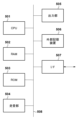
図5は、上記各実施形態に係る画像表示装置に適用可能なコンピュータのハードウェアの構成例を示すブロック図である。 Figure 5 is a block diagram showing an example of the hardware configuration of a computer that can be applied to the image display device according to each of the above embodiments.
CPU501は、RAM502やROM503に格納されているコンピュータプログラムやデータを用いてコンピュータ全体の制御を行うと共に、上記各実施形態に係る画像処理装置が行うものとして上述した各処理を実行する。即ち、CPU501は、図1、図2に示した各処理部として機能することになる。
The
RAM502は、外部記憶装置506からロードされたコンピュータプログラムやデータ、I/F(インターフェース)507を介して外部から取得したデータなどを一時的に記憶するためのエリアを有する。更に、RAM502は、CPU501が各種の処理を実行する際に用いるワークエリアを有する。即ち、RAM502は、例えば、フレームメモリとして割り当てたり、その他の各種のエリアを適宜提供したりすることができる。
ROM503には、本コンピュータの設定データや、ブートプログラムなどが格納されている。操作部504は、キーボードやマウスなどにより構成されており、本コンピュータのユーザが操作することで、各種の指示をCPU501に対して入力することができる。表示部505は、CPU501による処理結果を表示する。また表示部505は例えば液晶ディスプレイで構成される。
The
外部記憶装置506は、ハードディスクドライブ装置に代表される、大容量情報記憶装置である。外部記憶装置506には、OS(オペレーティングシステム)や、図1、図2に示した各部の機能をCPU501に実現させるためのコンピュータプログラムが保存されている。更には、外部記憶装置506には、処理対象としての各画像データが保存されていても良い。
The
外部記憶装置506に保存されているコンピュータプログラムやデータは、CPU501による制御に従って適宜、RAM502にロードされ、CPU501による処理対象となる。I/F507には、LANやインターネット等のネットワーク、投影装置や表示装置などの他の機器を接続することができ、本コンピュータはこのI/F507を介して様々な情報を取得したり、送出したりすることができる。508は上述の各部を繋ぐバスである。
Computer programs and data stored in
上記構成において、本装置の電源がONになると、CPU501はROM503のブートプログラムを実行して、外部記憶装置506に格納されたOSをRAM502にロードし、OSを起動する。この結果、本装置が、インターフェース507を介した通信が可能となり、情報処理装置として機能する。そして、OSの制御下で、CPU501は画像符号化に係るアプリケーション(図3に相当する)を外部記憶装置506からRAM502にロードして実行することで、CPU501が図1に示す各種処理部として機能することになり、本装置が画像符号化装置として機能することになる。一方、CPU501は画像復号に係るアプリケーション(図4に相当する)を外部記憶装置506からRAM502にロードして実行した場合、CPU501は図2に示す各種処理部として機能することになり、本装置が画像復号装置として機能することになる。
In the above configuration, when the power supply of the present device is turned on, the
(その他の実施例)
本発明は、上述の実施形態の1以上の機能を実現するプログラムを、ネットワーク又は記憶媒体を介してシステム又は装置に供給し、そのシステム又は装置のコンピュータにおける1つ以上のプロセッサーがプログラムを読出し実行する処理でも実現可能である。また、1以上の機能を実現する回路(例えば、ASIC)によっても実現可能である。
Other Examples
The present invention can also be realized by a process in which a program for implementing one or more of the functions of the above-described embodiments is supplied to a system or device via a network or a storage medium, and one or more processors in a computer of the system or device read and execute the program. The present invention can also be realized by a circuit (e.g., ASIC) that implements one or more of the functions.
101…入力端子、102…ブロック分割部、103…量子化マトリクス保持部、104…予測部、105…変換・量子化部、106…逆量子化・逆変換部、107…画像再生部、108…フレームメモリ、109…インループフィルタ部、110…符号化部、111…統合符号化部、112…出力端子、113…量子化マトリクス符号化部 101...input terminal, 102...block division unit, 103...quantization matrix storage unit, 104...prediction unit, 105...transformation and quantization unit, 106...inverse quantization and inverse transformation unit, 107...image reproduction unit, 108...frame memory, 109...in-loop filter unit, 110...encoding unit, 111...integrated encoding unit, 112...output terminal, 113...quantization matrix encoding unit
Claims (26)
量子化された変換係数から変換係数を導出する逆量子化処理において用いられる量子化マトリクスの少なくとも一部の要素に対応する複数の値を示すデータを復号する復号手段と、
前記データから前記複数の値を導出し、少なくとも当該複数の値に基づいて、前記量子化マトリクスを生成する生成手段と、
前記量子化マトリクスを用いて、対象ブロックの前記逆量子化処理を行う逆量子化手段と
を有し、
前記対象ブロックの幅が16画素で高さが8画素の場合、前記生成手段は、
前記複数の値の内の第1の値であって所定の初期値との差分によって導出される前記第1の値を、前記量子化マトリクスにおけるDC成分に対応する第1の要素に対応付けるとともに前記量子化マトリクスにおける他の要素には対応付けず、
前記複数の値の内の第2の値であって前記第1の値との差分によって導出される前記第2の値を、前記量子化マトリクスにおいて前記第1の要素の右に隣接する第2の要素に対応付けるとともに前記量子化マトリクスにおける他の要素には対応付けず、
前記複数の値の内の第3の値であって前記第2の値との差分によって導出される前記第3の値を、前記量子化マトリクスにおいて前記第1の要素の下に隣接する第3の要素と、前記量子化マトリクスにおいて前記第2の要素の下に隣接する第4の要素とに対応付けることで、
前記量子化マトリクスを生成する
ことを特徴とする画像復号装置。 An image decoding device that decodes an image from encoded data, comprising:
A decoding means for decoding data indicating a plurality of values corresponding to at least some elements of a quantization matrix used in an inverse quantization process for deriving transform coefficients from the quantized transform coefficients;
generation means for deriving the values from the data and generating the quantization matrix based on at least the values;
an inverse quantization means for performing the inverse quantization process on a target block by using the quantization matrix;
When the target block has a width of 16 pixels and a height of 8 pixels, the generating means
a first value among the plurality of values, the first value being derived by a difference from a predetermined initial value , is associated with a first element corresponding to a DC component in the quantization matrix, and is not associated with other elements in the quantization matrix;
a second value among the plurality of values, the second value being derived by a difference from the first value , is associated with a second element adjacent to the right of the first element in the quantization matrix, and is not associated with any other element in the quantization matrix;
a third value among the plurality of values, the third value being derived by a difference between the third value and the second value , is associated with a third element adjacent below the first element in the quantization matrix, and a fourth element adjacent below the second element in the quantization matrix,
The image decoding device generates the quantization matrix.
ことを特徴とする請求項1に記載の画像復号装置。 The image decoding device according to claim 1 , wherein the third value of the plurality of values is not associated with any element other than the third and fourth elements in the quantization matrix.
ことを特徴とする請求項1に記載の画像復号装置。 The image decoding device according to claim 1 , wherein the data indicating the plurality of values indicates a difference between the plurality of values.
を更に有することを特徴とする請求項1に記載の画像復号装置。 2. The image decoding device according to claim 1, further comprising a selection means for selecting a quantization matrix to be used in the inverse quantization process depending on whether intra prediction or inter prediction is used.
を更に有することを特徴とする請求項1に記載の画像復号装置。 2. The image decoding device according to claim 1, further comprising: a selection means for selecting a quantization matrix to be used in the inverse quantization process depending on whether a block to be decoded is a luminance block or a chrominance block.
ことを特徴とする請求項1に記載の画像復号装置。 The number of the plurality of values is one more than half the number of elements constituting the quantization matrix.
2. The image decoding device according to claim 1.
量子化マトリクスを用いて対象ブロックの量子化処理を行う量子化手段と、
前記量子化マトリクスの少なくとも一部の要素に対応する複数の値を示すデータを符号化する符号化手段と、
を有し、
前記対象ブロックの幅が16画素で高さが8画素の場合、前記符号化手段は、
前記量子化マトリクスにおけるDC成分に対応する第1の要素に対応付けられるとともに前記量子化マトリクスにおける他の要素には対応付けられない第1の値と所定の初期値との差分を示すデータと、
前記量子化マトリクスにおいて前記第1の要素の右に隣接する第2の要素に対応付けられるとともに前記量子化マトリクスにおける他の要素には対応付けられない第2の値と前記第1の値との差分を示すデータと、
前記量子化マトリクスにおいて前記第1の要素の下に隣接する第3の要素と、前記量子化マトリクスにおいて前記第2の要素の下に隣接する第4の要素とに対応付けられる第3の値と前記第2の値との差分を示すデータと
を少なくとも符号化することで、前記複数の値を示すデータを符号化する
ことを特徴とする画像符号化装置。 An image encoding device that encodes an image, comprising:
quantization means for performing a quantization process on a target block using a quantization matrix;
an encoding means for encoding data indicating a plurality of values corresponding to at least some elements of the quantization matrix;
having
When the width of the target block is 16 pixels and the height is 8 pixels, the encoding means
data indicating a difference between a first value, which is associated with a first element corresponding to a DC component in the quantization matrix and is not associated with other elements in the quantization matrix, and a predetermined initial value ;
data indicating a difference between the first value and a second value that is associated with a second element adjacent to the right of the first element in the quantization matrix and is not associated with any other element in the quantization matrix;
an image coding device that codes the data indicating the multiple values by coding at least data indicating a difference between the second value and a third value associated with a third element adjacent below the first element in the quantization matrix and a fourth element adjacent below the second element in the quantization matrix.
ことを特徴とする請求項7に記載の画像符号化装置。 The image encoding device according to claim 7 , wherein the third value is not associated with any element other than the third and fourth elements in the quantization matrix.
ことを特徴とする請求項7に記載の画像符号化装置。 The image encoding device according to claim 7 , wherein the data indicating the plurality of values indicates a difference between the plurality of values.
を更に有することを特徴とする請求項7に記載の画像符号化装置。 8. The image encoding device according to claim 7, further comprising a selection means for selecting a quantization matrix to be used in the quantization process depending on whether intra-prediction or inter-prediction is used.
を更に有することを特徴とする請求項7に記載の画像符号化装置。 8. The image encoding device according to claim 7, further comprising a selection means for selecting a quantization matrix to be used in said quantization process depending on whether a target block is a luminance block or a chrominance block.
ことを特徴とする請求項7に記載の画像符号化装置。 The number of the plurality of values is one more than half the number of elements constituting the quantization matrix.
8. The image encoding device according to claim 7.
量子化された変換係数から変換係数を導出する逆量子化処理において用いられる量子化マトリクスの少なくとも一部の要素に対応する複数の値を示すデータを復号する復号ステップと、
前記データから前記複数の値を導出し、少なくとも当該複数の値に基づいて、前記量子化マトリクスを生成する生成ステップと、
前記量子化マトリクスを用いて、対象ブロックの前記逆量子化処理を行う逆量子化ステップと
を有し、
前記対象ブロックの幅が16画素で高さが8画素の場合、前記生成ステップにおいて、
前記複数の値の内の第1の値であって所定の初期値との差分によって導出される前記第1の値を、前記量子化マトリクスにおけるDC成分に対応する第1の要素に対応付けるとともに前記量子化マトリクスにおける他の要素には対応付けず、
前記複数の値の内の第2の値であって前記第1の値との差分によって導出される前記第2の値を、前記量子化マトリクスにおいて前記第1の要素の右に隣接する第2の要素に対応付けるとともに前記量子化マトリクスにおける他の要素には対応付けず、
前記複数の値の内の第3の値であって前記第2の値との差分によって導出される前記第3の値を、前記量子化マトリクスにおいて前記第1の要素の下に隣接する第3の要素と、前記量子化マトリクスにおいて前記第2の要素の下に隣接する第4の要素とに対応付けることで、
前記量子化マトリクスを生成する
ことを特徴とする画像復号方法。 1. An image decoding method for decoding an image from encoded data, comprising the steps of:
a decoding step of decoding data indicating a plurality of values corresponding to at least some elements of a quantization matrix used in an inverse quantization process for deriving transform coefficients from the quantized transform coefficients;
a generating step of deriving the values from the data and generating the quantization matrix based on at least the values;
an inverse quantization step of performing the inverse quantization process on the current block using the quantization matrix;
If the target block has a width of 16 pixels and a height of 8 pixels, the generating step
a first value among the plurality of values, the first value being derived by a difference from a predetermined initial value , is associated with a first element corresponding to a DC component in the quantization matrix, and is not associated with other elements in the quantization matrix;
a second value among the plurality of values, the second value being derived by a difference from the first value , is associated with a second element adjacent to the right of the first element in the quantization matrix, and is not associated with any other element in the quantization matrix;
a third value among the plurality of values, the third value being derived by a difference between the third value and the second value , is associated with a third element adjacent below the first element in the quantization matrix, and a fourth element adjacent below the second element in the quantization matrix,
generating the quantization matrix.
ことを特徴とする請求項13に記載の画像復号方法。 The image decoding method according to claim 13 , wherein the third value of the plurality of values is not associated with any element other than the third and fourth elements in the quantization matrix.
ことを特徴とする請求項13に記載の画像復号方法。 The image decoding method according to claim 13 , wherein the data indicating the plurality of values indicates a difference between the plurality of values.
を更に有することを特徴とする請求項13に記載の画像復号方法。 The image decoding method according to claim 13 , further comprising a selection step of selecting a quantization matrix to be used in the inverse quantization process depending on whether intra prediction or inter prediction is used.
を更に有することを特徴とする請求項13に記載の画像復号方法。 14. The image decoding method according to claim 13, further comprising a selection step of selecting a quantization matrix to be used in the inverse quantization process depending on whether a block to be decoded is a luminance block or a chrominance block.
ことを特徴とする請求項13に記載の画像復号方法。 The number of the plurality of values is one more than half the number of elements constituting the quantization matrix.
The image decoding method according to claim 13 .
量子化マトリクスを用いて対象ブロックの量子化処理を行う量子化ステップと、
前記量子化マトリクスの少なくとも一部の要素に対応する複数の値を示すデータを符号化する符号化ステップと、
を有し、
前記対象ブロックの幅が16画素で高さが8画素の場合、前記符号化ステップにおいて、
前記量子化マトリクスにおけるDC成分に対応する第1の要素に対応付けられるとともに前記量子化マトリクスにおける他の要素には対応付けられない第1の値と所定の初期値との差分を示すデータと、
前記量子化マトリクスにおいて前記第1の要素の右に隣接する第2の要素に対応付けられるとともに前記量子化マトリクスにおける他の要素には対応付けられない第2の値と前記第1の値との差分を示すデータと、
前記量子化マトリクスにおいて前記第1の要素の下に隣接する第3の要素と、前記量子化マトリクスにおいて前記第2の要素の下に隣接する第4の要素とに対応付けられる第3の値と前記第2の値との差分を示すデータと
を少なくとも符号化することで、前記複数の値を示すデータを符号化する
ことを特徴とする画像符号化方法。 1. An image encoding method for encoding an image, comprising the steps of:
a quantization step of performing a quantization process on a target block using a quantization matrix;
an encoding step of encoding data indicating a plurality of values corresponding to at least some elements of the quantization matrix;
having
If the current block has a width of 16 pixels and a height of 8 pixels, then the encoding step
data indicating a difference between a first value, which is associated with a first element corresponding to a DC component in the quantization matrix and is not associated with other elements in the quantization matrix, and a predetermined initial value ;
data indicating a difference between the first value and a second value that is associated with a second element adjacent to the right of the first element in the quantization matrix and is not associated with any other element in the quantization matrix;
an image coding method comprising: coding at least data indicating a difference between the second value and a third value associated with a third element adjacent below the first element in the quantization matrix and a fourth element adjacent below the second element in the quantization matrix, the data indicating the plurality of values being coded;
ことを特徴とする請求項19に記載の画像符号化方法。 20. The image coding method according to claim 19, wherein the third value is not associated with any element in the quantization matrix other than the third and fourth elements.
ことを特徴とする請求項19に記載の画像符号化方法。 The image coding method according to claim 19 , wherein the data indicating the plurality of values indicates a difference between a plurality of values.
を更に有することを特徴とする請求項19に記載の画像符号化方法。 20. The image encoding method according to claim 19, further comprising a selection step of selecting a quantization matrix to be used in the quantization process depending on whether intra prediction or inter prediction is used.
を更に有することを特徴とする請求項19に記載の画像符号化方法。 20. The image coding method according to claim 19, further comprising a selection step of selecting a quantization matrix to be used in the quantization process depending on whether a target block is a luminance block or a chrominance block.
ことを特徴とする請求項19に記載の画像符号化方法。 The number of the plurality of values is one more than half the number of elements constituting the quantization matrix.
20. The image coding method according to claim 19.
Priority Applications (23)
| Application Number | Priority Date | Filing Date | Title |
|---|---|---|---|
| JP2018235910A JP7672190B2 (en) | 2018-12-17 | 2018-12-17 | Image encoding device, image decoding device, and control method and program thereof |
| CN202410387636.XA CN118233635A (en) | 2018-12-17 | 2019-11-14 | Image encoding device and method, image decoding device and method, and storage medium |
| CN202410387644.4A CN118175316A (en) | 2018-12-17 | 2019-11-14 | Image encoding device and method, image decoding device and method, and storage medium |
| CN202410387841.6A CN118175317A (en) | 2018-12-17 | 2019-11-14 | Image encoding device and method, image decoding device and method, and storage medium |
| KR1020217021605A KR102756978B1 (en) | 2018-12-17 | 2019-11-14 | Image encoding device and image decoding device and their control method and program |
| CN201980083874.9A CN113228652B (en) | 2018-12-17 | 2019-11-14 | Image encoding device and method, image decoding device and method, and storage medium |
| CN202410387641.0A CN118175315A (en) | 2018-12-17 | 2019-11-14 | Image encoding device and method, image decoding device and method, and storage medium |
| PCT/JP2019/044754 WO2020129489A1 (en) | 2018-12-17 | 2019-11-14 | Image encoding device, image decoding device, and method and program for controlling same |
| BR112021010308-2A BR112021010308A2 (en) | 2018-12-17 | 2019-11-14 | Image encoding device, image decoding device, and method and program for controlling them |
| CN202410387843.5A CN118175318A (en) | 2018-12-17 | 2019-11-14 | Image encoding device and method, image decoding device and method, and storage medium |
| EP19897736.5A EP3902254A4 (en) | 2018-12-17 | 2019-11-14 | IMAGE ENCODING DEVICE, IMAGE DECODING DEVICE, AND METHOD AND PROGRAM FOR CONTROLLING THEM |
| TW108142735A TWI770441B (en) | 2018-12-17 | 2019-11-25 | Image encoding device, image decoding device, control method and program thereof |
| TW111143485A TW202312733A (en) | 2018-12-17 | 2019-11-25 | Image encoding device, image decoding device, and method and program for controlling same |
| TW111122003A TWI788268B (en) | 2018-12-17 | 2019-11-25 | Image encoding device, image decoding device, control method and program thereof |
| TW113101548A TWI881668B (en) | 2018-12-17 | 2019-11-25 | Image encoding device, image decoding device, control method and program thereof |
| US17/346,849 US11997276B2 (en) | 2018-12-17 | 2021-06-14 | Image encoding apparatus, image decoding apparatus, control methods and non-transitory computer-readable storage medium |
| JP2023216192A JP7685038B2 (en) | 2018-12-17 | 2023-12-21 | Image encoding device, image decoding device, image encoding method, image decoding method, and program |
| US18/443,101 US12170770B2 (en) | 2018-12-17 | 2024-02-15 | Image encoding apparatus, image decoding apparatus, control methods and non-transitory computer-readable storage medium |
| US18/443,073 US12294703B2 (en) | 2018-12-17 | 2024-02-15 | Image encoding apparatus, image decoding apparatus, control methods and non-transitory computer-readable storage medium |
| US18/443,082 US12294704B2 (en) | 2018-12-17 | 2024-02-15 | Image encoding apparatus, image decoding apparatus, control methods and non-transitory computer-readable storage medium |
| US18/443,089 US12464126B2 (en) | 2018-12-17 | 2024-02-15 | Image encoding apparatus, image decoding apparatus, control methods and non-transitory computer-readable storage medium |
| US18/443,107 US12323592B2 (en) | 2018-12-17 | 2024-02-15 | Image encoding apparatus, image decoding apparatus, control methods and non-transitory computer-readable storage medium |
| US19/202,949 US20250267266A1 (en) | 2018-12-17 | 2025-05-08 | Image encoding apparatus, image decoding apparatus, control methods and non-transitory computer-readable storage medium |
Applications Claiming Priority (1)
| Application Number | Priority Date | Filing Date | Title |
|---|---|---|---|
| JP2018235910A JP7672190B2 (en) | 2018-12-17 | 2018-12-17 | Image encoding device, image decoding device, and control method and program thereof |
Related Child Applications (1)
| Application Number | Title | Priority Date | Filing Date |
|---|---|---|---|
| JP2023216192A Division JP7685038B2 (en) | 2018-12-17 | 2023-12-21 | Image encoding device, image decoding device, image encoding method, image decoding method, and program |
Publications (3)
| Publication Number | Publication Date |
|---|---|
| JP2020098984A JP2020098984A (en) | 2020-06-25 |
| JP2020098984A5 JP2020098984A5 (en) | 2021-12-16 |
| JP7672190B2 true JP7672190B2 (en) | 2025-05-07 |
Family
ID=71101173
Family Applications (2)
| Application Number | Title | Priority Date | Filing Date |
|---|---|---|---|
| JP2018235910A Active JP7672190B2 (en) | 2018-12-17 | 2018-12-17 | Image encoding device, image decoding device, and control method and program thereof |
| JP2023216192A Active JP7685038B2 (en) | 2018-12-17 | 2023-12-21 | Image encoding device, image decoding device, image encoding method, image decoding method, and program |
Family Applications After (1)
| Application Number | Title | Priority Date | Filing Date |
|---|---|---|---|
| JP2023216192A Active JP7685038B2 (en) | 2018-12-17 | 2023-12-21 | Image encoding device, image decoding device, image encoding method, image decoding method, and program |
Country Status (8)
| Country | Link |
|---|---|
| US (7) | US11997276B2 (en) |
| EP (1) | EP3902254A4 (en) |
| JP (2) | JP7672190B2 (en) |
| KR (1) | KR102756978B1 (en) |
| CN (6) | CN118175317A (en) |
| BR (1) | BR112021010308A2 (en) |
| TW (4) | TWI881668B (en) |
| WO (1) | WO2020129489A1 (en) |
Families Citing this family (2)
| Publication number | Priority date | Publication date | Assignee | Title |
|---|---|---|---|---|
| US11490122B2 (en) * | 2020-09-24 | 2022-11-01 | Tencent America LLC | Method and apparatus for video coding |
| CN118741117B (en) * | 2024-08-29 | 2024-11-19 | 中国兵工物资集团有限公司 | Image data packet generation method and image restoration method based on image data packet |
Citations (4)
| Publication number | Priority date | Publication date | Assignee | Title |
|---|---|---|---|---|
| WO2013094385A1 (en) | 2011-12-19 | 2013-06-27 | ソニー株式会社 | Image processing device and method |
| JP2013146038A (en) | 2011-12-13 | 2013-07-25 | Canon Inc | Image quantization apparatus, image quantization method, and program, and image inverse quantization apparatus, image inverse quantization method, and program |
| WO2013129616A1 (en) | 2012-02-29 | 2013-09-06 | ソニー株式会社 | Image processing device and method |
| JP2014535250A (en) | 2011-11-07 | 2014-12-25 | クゥアルコム・インコーポレイテッドQualcomm Incorporated | Quantization matrix signaling for video coding |
Family Cites Families (18)
| Publication number | Priority date | Publication date | Assignee | Title |
|---|---|---|---|---|
| US6882685B2 (en) | 2001-09-18 | 2005-04-19 | Microsoft Corporation | Block transform and quantization for image and video coding |
| JP4956612B2 (en) * | 2006-10-12 | 2012-06-20 | 株式会社東芝 | Image coding apparatus and image coding method |
| JP2011029956A (en) * | 2009-07-27 | 2011-02-10 | Sony Corp | Image coding apparatus and image coding method |
| US9215470B2 (en) | 2010-07-09 | 2015-12-15 | Qualcomm Incorporated | Signaling selected directional transform for video coding |
| JP5741076B2 (en) * | 2010-12-09 | 2015-07-01 | ソニー株式会社 | Image processing apparatus and image processing method |
| US9641840B2 (en) * | 2011-05-20 | 2017-05-02 | Sony Corporation | Processing device and image processing method for encoding and decoding image |
| JP2013038758A (en) * | 2011-07-13 | 2013-02-21 | Canon Inc | Image encoder, image encoding method, program, image decoder, image decoding method and program |
| CN103797796B (en) | 2011-09-08 | 2017-04-19 | 谷歌技术控股有限责任公司 | Methods and apparatus for quantization and dequantization of a rectangular block of coefficients |
| TW201325247A (en) | 2011-11-07 | 2013-06-16 | Samsung Electronics Co Ltd | Inverse transformation method and inverse transformation apparatus for clipping data during inverse quantization and inverse transformation in video decoding process |
| WO2013158669A1 (en) * | 2012-04-16 | 2013-10-24 | Huawei Technologies Co., Ltd. | Method and apparatus of quantization matrix coding |
| PT2840791T (en) * | 2012-04-16 | 2018-04-16 | Electronics & Telecommunications Res Inst | METHOD AND DEVICE FOR CODING / DECODING IMAGE |
| GB2501535A (en) * | 2012-04-26 | 2013-10-30 | Sony Corp | Chrominance Processing in High Efficiency Video Codecs |
| TWI627857B (en) | 2012-06-29 | 2018-06-21 | 新力股份有限公司 | Image processing device and method |
| CN106663209B (en) * | 2014-09-19 | 2020-05-08 | 华为技术有限公司 | Method and apparatus for non-uniformly mapping quantization matrix coefficients between quantization matrices of different sizes in image/video coding |
| JPWO2016103542A1 (en) * | 2014-12-26 | 2017-10-19 | パナソニックIpマネジメント株式会社 | Encoding method, decoding method, encoding device, and decoding device |
| CN104796609B (en) * | 2015-04-17 | 2018-01-05 | 南京理工大学 | Large visual field high resolution micro imaging method based on optimal Hadamard coding |
| JP6566865B2 (en) * | 2015-12-28 | 2019-08-28 | Kddi株式会社 | Moving picture decoding apparatus, moving picture decoding method, moving picture encoding apparatus, moving picture encoding method, and computer-readable recording medium |
| CN106612439A (en) * | 2016-02-04 | 2017-05-03 | 四川用联信息技术有限公司 | Adaptive fast fractal image compression method |
-
2018
- 2018-12-17 JP JP2018235910A patent/JP7672190B2/en active Active
-
2019
- 2019-11-14 CN CN202410387841.6A patent/CN118175317A/en active Pending
- 2019-11-14 BR BR112021010308-2A patent/BR112021010308A2/en unknown
- 2019-11-14 CN CN202410387641.0A patent/CN118175315A/en active Pending
- 2019-11-14 CN CN202410387644.4A patent/CN118175316A/en active Pending
- 2019-11-14 CN CN202410387843.5A patent/CN118175318A/en active Pending
- 2019-11-14 WO PCT/JP2019/044754 patent/WO2020129489A1/en not_active Ceased
- 2019-11-14 EP EP19897736.5A patent/EP3902254A4/en active Pending
- 2019-11-14 CN CN201980083874.9A patent/CN113228652B/en active Active
- 2019-11-14 CN CN202410387636.XA patent/CN118233635A/en active Pending
- 2019-11-14 KR KR1020217021605A patent/KR102756978B1/en active Active
- 2019-11-25 TW TW113101548A patent/TWI881668B/en active
- 2019-11-25 TW TW108142735A patent/TWI770441B/en active
- 2019-11-25 TW TW111143485A patent/TW202312733A/en unknown
- 2019-11-25 TW TW111122003A patent/TWI788268B/en active
-
2021
- 2021-06-14 US US17/346,849 patent/US11997276B2/en active Active
-
2023
- 2023-12-21 JP JP2023216192A patent/JP7685038B2/en active Active
-
2024
- 2024-02-15 US US18/443,082 patent/US12294704B2/en active Active
- 2024-02-15 US US18/443,073 patent/US12294703B2/en active Active
- 2024-02-15 US US18/443,107 patent/US12323592B2/en active Active
- 2024-02-15 US US18/443,101 patent/US12170770B2/en active Active
- 2024-02-15 US US18/443,089 patent/US12464126B2/en active Active
-
2025
- 2025-05-08 US US19/202,949 patent/US20250267266A1/en active Pending
Patent Citations (4)
| Publication number | Priority date | Publication date | Assignee | Title |
|---|---|---|---|---|
| JP2014535250A (en) | 2011-11-07 | 2014-12-25 | クゥアルコム・インコーポレイテッドQualcomm Incorporated | Quantization matrix signaling for video coding |
| JP2013146038A (en) | 2011-12-13 | 2013-07-25 | Canon Inc | Image quantization apparatus, image quantization method, and program, and image inverse quantization apparatus, image inverse quantization method, and program |
| WO2013094385A1 (en) | 2011-12-19 | 2013-06-27 | ソニー株式会社 | Image processing device and method |
| WO2013129616A1 (en) | 2012-02-29 | 2013-09-06 | ソニー株式会社 | Image processing device and method |
Non-Patent Citations (1)
| Title |
|---|
| Recommendation ITU-T H.265 (04/2013) |
Also Published As
Similar Documents
| Publication | Publication Date | Title |
|---|---|---|
| JP7819381B2 (en) | Image encoding device, image encoding method, and program | |
| JP7497486B2 (en) | Image decoding device, image decoding method, and program | |
| JP7685038B2 (en) | Image encoding device, image decoding device, image encoding method, image decoding method, and program | |
| JP7819382B2 (en) | Image decoding device, image decoding method, and program | |
| JP7685102B2 (en) | Image encoding device, image decoding device, and control method and program thereof | |
| JP2020010320A (en) | Image encoding device, image decoding device, control method of them, and program | |
| HK40106551A (en) | Image encoding device and method, image decoding device and method, and storage medium | |
| HK40106325A (en) | Image encoding device and method, image decoding device and method, and storage medium | |
| HK40106550A (en) | Image encoding device and method, image decoding device and method, and storage medium | |
| HK40106324A (en) | Image encoding device and method, image decoding device and method, and storage medium | |
| HK40106323A (en) | Image encoding device and method, image decoding device and method, and storage medium |
Legal Events
| Date | Code | Title | Description |
|---|---|---|---|
| RD01 | Notification of change of attorney |
Free format text: JAPANESE INTERMEDIATE CODE: A7421 Effective date: 20210103 |
|
| A521 | Request for written amendment filed |
Free format text: JAPANESE INTERMEDIATE CODE: A523 Effective date: 20210113 |
|
| A521 | Request for written amendment filed |
Free format text: JAPANESE INTERMEDIATE CODE: A523 Effective date: 20211101 |
|
| A621 | Written request for application examination |
Free format text: JAPANESE INTERMEDIATE CODE: A621 Effective date: 20211101 |
|
| A131 | Notification of reasons for refusal |
Free format text: JAPANESE INTERMEDIATE CODE: A131 Effective date: 20221024 |
|
| A521 | Request for written amendment filed |
Free format text: JAPANESE INTERMEDIATE CODE: A523 Effective date: 20221216 |
|
| A131 | Notification of reasons for refusal |
Free format text: JAPANESE INTERMEDIATE CODE: A131 Effective date: 20230414 |
|
| A521 | Request for written amendment filed |
Free format text: JAPANESE INTERMEDIATE CODE: A523 Effective date: 20230607 |
|
| A02 | Decision of refusal |
Free format text: JAPANESE INTERMEDIATE CODE: A02 Effective date: 20231002 |
|
| A521 | Request for written amendment filed |
Free format text: JAPANESE INTERMEDIATE CODE: A523 Effective date: 20231221 |
|
| A911 | Transfer to examiner for re-examination before appeal (zenchi) |
Free format text: JAPANESE INTERMEDIATE CODE: A911 Effective date: 20240109 |
|
| A912 | Re-examination (zenchi) completed and case transferred to appeal board |
Free format text: JAPANESE INTERMEDIATE CODE: A912 Effective date: 20240315 |
|
| A61 | First payment of annual fees (during grant procedure) |
Free format text: JAPANESE INTERMEDIATE CODE: A61 Effective date: 20250422 |
|
| R150 | Certificate of patent or registration of utility model |
Ref document number: 7672190 Country of ref document: JP Free format text: JAPANESE INTERMEDIATE CODE: R150 |