JP7674511B2 - Turbine vanes - Google Patents
Turbine vanes Download PDFInfo
- Publication number
- JP7674511B2 JP7674511B2 JP2023563659A JP2023563659A JP7674511B2 JP 7674511 B2 JP7674511 B2 JP 7674511B2 JP 2023563659 A JP2023563659 A JP 2023563659A JP 2023563659 A JP2023563659 A JP 2023563659A JP 7674511 B2 JP7674511 B2 JP 7674511B2
- Authority
- JP
- Japan
- Prior art keywords
- shroud
- inner shroud
- passage
- turbine
- airfoil portion
- Prior art date
- Legal status (The legal status is an assumption and is not a legal conclusion. Google has not performed a legal analysis and makes no representation as to the accuracy of the status listed.)
- Active
Links
Images



Classifications
-
- F—MECHANICAL ENGINEERING; LIGHTING; HEATING; WEAPONS; BLASTING
- F01—MACHINES OR ENGINES IN GENERAL; ENGINE PLANTS IN GENERAL; STEAM ENGINES
- F01D—NON-POSITIVE DISPLACEMENT MACHINES OR ENGINES, e.g. STEAM TURBINES
- F01D9/00—Stators
- F01D9/02—Nozzles; Nozzle boxes; Stator blades; Guide conduits, e.g. individual nozzles
- F01D9/023—Transition ducts between combustor cans and first stage of the turbine in gas-turbine engines; their cooling or sealings
-
- F—MECHANICAL ENGINEERING; LIGHTING; HEATING; WEAPONS; BLASTING
- F01—MACHINES OR ENGINES IN GENERAL; ENGINE PLANTS IN GENERAL; STEAM ENGINES
- F01D—NON-POSITIVE DISPLACEMENT MACHINES OR ENGINES, e.g. STEAM TURBINES
- F01D5/00—Blades; Blade-carrying members; Heating, heat-insulating, cooling or antivibration means on the blades or the members
- F01D5/12—Blades
- F01D5/14—Form or construction
- F01D5/18—Hollow blades, i.e. blades with cooling or heating channels or cavities; Heating, heat-insulating or cooling means on blades
-
- F—MECHANICAL ENGINEERING; LIGHTING; HEATING; WEAPONS; BLASTING
- F01—MACHINES OR ENGINES IN GENERAL; ENGINE PLANTS IN GENERAL; STEAM ENGINES
- F01D—NON-POSITIVE DISPLACEMENT MACHINES OR ENGINES, e.g. STEAM TURBINES
- F01D5/00—Blades; Blade-carrying members; Heating, heat-insulating, cooling or antivibration means on the blades or the members
- F01D5/12—Blades
- F01D5/14—Form or construction
- F01D5/18—Hollow blades, i.e. blades with cooling or heating channels or cavities; Heating, heat-insulating or cooling means on blades
- F01D5/187—Convection cooling
-
- F—MECHANICAL ENGINEERING; LIGHTING; HEATING; WEAPONS; BLASTING
- F01—MACHINES OR ENGINES IN GENERAL; ENGINE PLANTS IN GENERAL; STEAM ENGINES
- F01D—NON-POSITIVE DISPLACEMENT MACHINES OR ENGINES, e.g. STEAM TURBINES
- F01D5/00—Blades; Blade-carrying members; Heating, heat-insulating, cooling or antivibration means on the blades or the members
- F01D5/12—Blades
- F01D5/22—Blade-to-blade connections, e.g. for damping vibrations
- F01D5/225—Blade-to-blade connections, e.g. for damping vibrations by shrouding
-
- F—MECHANICAL ENGINEERING; LIGHTING; HEATING; WEAPONS; BLASTING
- F01—MACHINES OR ENGINES IN GENERAL; ENGINE PLANTS IN GENERAL; STEAM ENGINES
- F01D—NON-POSITIVE DISPLACEMENT MACHINES OR ENGINES, e.g. STEAM TURBINES
- F01D5/00—Blades; Blade-carrying members; Heating, heat-insulating, cooling or antivibration means on the blades or the members
- F01D5/12—Blades
- F01D5/28—Selecting particular materials; Particular measures relating thereto; Measures against erosion or corrosion
- F01D5/288—Protective coatings for blades
-
- F—MECHANICAL ENGINEERING; LIGHTING; HEATING; WEAPONS; BLASTING
- F01—MACHINES OR ENGINES IN GENERAL; ENGINE PLANTS IN GENERAL; STEAM ENGINES
- F01D—NON-POSITIVE DISPLACEMENT MACHINES OR ENGINES, e.g. STEAM TURBINES
- F01D9/00—Stators
- F01D9/02—Nozzles; Nozzle boxes; Stator blades; Guide conduits, e.g. individual nozzles
-
- F—MECHANICAL ENGINEERING; LIGHTING; HEATING; WEAPONS; BLASTING
- F02—COMBUSTION ENGINES; HOT-GAS OR COMBUSTION-PRODUCT ENGINE PLANTS
- F02C—GAS-TURBINE PLANTS; AIR INTAKES FOR JET-PROPULSION PLANTS; CONTROLLING FUEL SUPPLY IN AIR-BREATHING JET-PROPULSION PLANTS
- F02C7/00—Features, components parts, details or accessories, not provided for in, or of interest apart form groups F02C1/00 - F02C6/00; Air intakes for jet-propulsion plants
- F02C7/12—Cooling of plants
- F02C7/16—Cooling of plants characterised by cooling medium
- F02C7/18—Cooling of plants characterised by cooling medium the medium being gaseous, e.g. air
-
- F—MECHANICAL ENGINEERING; LIGHTING; HEATING; WEAPONS; BLASTING
- F05—INDEXING SCHEMES RELATING TO ENGINES OR PUMPS IN VARIOUS SUBCLASSES OF CLASSES F01-F04
- F05D—INDEXING SCHEME FOR ASPECTS RELATING TO NON-POSITIVE-DISPLACEMENT MACHINES OR ENGINES, GAS-TURBINES OR JET-PROPULSION PLANTS
- F05D2220/00—Application
- F05D2220/30—Application in turbines
- F05D2220/32—Application in turbines in gas turbines
-
- F—MECHANICAL ENGINEERING; LIGHTING; HEATING; WEAPONS; BLASTING
- F05—INDEXING SCHEMES RELATING TO ENGINES OR PUMPS IN VARIOUS SUBCLASSES OF CLASSES F01-F04
- F05D—INDEXING SCHEME FOR ASPECTS RELATING TO NON-POSITIVE-DISPLACEMENT MACHINES OR ENGINES, GAS-TURBINES OR JET-PROPULSION PLANTS
- F05D2240/00—Components
- F05D2240/10—Stators
- F05D2240/12—Fluid guiding means, e.g. vanes
-
- F—MECHANICAL ENGINEERING; LIGHTING; HEATING; WEAPONS; BLASTING
- F05—INDEXING SCHEMES RELATING TO ENGINES OR PUMPS IN VARIOUS SUBCLASSES OF CLASSES F01-F04
- F05D—INDEXING SCHEME FOR ASPECTS RELATING TO NON-POSITIVE-DISPLACEMENT MACHINES OR ENGINES, GAS-TURBINES OR JET-PROPULSION PLANTS
- F05D2240/00—Components
- F05D2240/80—Platforms for stationary or moving blades
- F05D2240/81—Cooled platforms
-
- F—MECHANICAL ENGINEERING; LIGHTING; HEATING; WEAPONS; BLASTING
- F05—INDEXING SCHEMES RELATING TO ENGINES OR PUMPS IN VARIOUS SUBCLASSES OF CLASSES F01-F04
- F05D—INDEXING SCHEME FOR ASPECTS RELATING TO NON-POSITIVE-DISPLACEMENT MACHINES OR ENGINES, GAS-TURBINES OR JET-PROPULSION PLANTS
- F05D2260/00—Function
- F05D2260/20—Heat transfer, e.g. cooling
- F05D2260/201—Heat transfer, e.g. cooling by impingement of a fluid
-
- F—MECHANICAL ENGINEERING; LIGHTING; HEATING; WEAPONS; BLASTING
- F05—INDEXING SCHEMES RELATING TO ENGINES OR PUMPS IN VARIOUS SUBCLASSES OF CLASSES F01-F04
- F05D—INDEXING SCHEME FOR ASPECTS RELATING TO NON-POSITIVE-DISPLACEMENT MACHINES OR ENGINES, GAS-TURBINES OR JET-PROPULSION PLANTS
- F05D2300/00—Materials; Properties thereof
- F05D2300/60—Properties or characteristics given to material by treatment or manufacturing
- F05D2300/611—Coating
Landscapes
- Engineering & Computer Science (AREA)
- Mechanical Engineering (AREA)
- General Engineering & Computer Science (AREA)
- Chemical & Material Sciences (AREA)
- Combustion & Propulsion (AREA)
- Materials Engineering (AREA)
- Turbine Rotor Nozzle Sealing (AREA)
Description
本開示は、タービン静翼に関する。
本願は、2021年11月29日に日本国特許庁に出願された特願2021-193277号に基づき優先権を主張し、その内容をここに援用する。
The present disclosure relates to turbine vanes.
This application claims priority based on Patent Application No. 2021-193277, filed with the Japan Patent Office on November 29, 2021, the contents of which are incorporated herein by reference.
例えば、ガスタービンなどに用いられるタービン静翼は、燃焼ガス等の高温の流体に曝されるため、冷却のための構造を有している。例えば特許文献1に記載のタービン静翼では、静翼本体(翼型部)と、内側シュラウドと、外側シュラウドとを、それぞれ冷却空気で冷却するようにしている(特許文献1参照)。
For example, turbine vanes used in gas turbines and the like have a cooling structure because they are exposed to high-temperature fluids such as combustion gas. For example, in the turbine vane described in
実機における燃焼ガスの温度を測定したところ、ハブ側の燃焼ガス温度が事前の想定よりも低いことが判明し、内側シュラウドのメタル温度も事前の想定よりも低いことが判明した。タービン静翼のメタル温度が事前に想定していた温度よりも低いと、ガスタービンの効率低下を招くため、タービン静翼のメタル温度は、事前に想定していた温度に近い温度であることが望まれる。 When the temperature of the combustion gas in the actual machine was measured, it was found that the combustion gas temperature on the hub side was lower than previously assumed, and that the metal temperature of the inner shroud was also lower than previously assumed. If the metal temperature of the turbine vanes is lower than previously assumed, it will lead to a decrease in the efficiency of the gas turbine, so it is desirable for the metal temperature of the turbine vanes to be close to the previously assumed temperature.
本開示の少なくとも一実施形態は、上述の事情に鑑みて、タービン静翼の冷却を適切化してタービン効率を向上することを目的とする。 In view of the above circumstances, at least one embodiment of the present disclosure aims to improve turbine efficiency by optimizing the cooling of turbine vanes.
(1)本開示の少なくとも一実施形態に係るタービン静翼は、
翼型部と、
前記翼型部の内周側に設けられる内側シュラウドと、
前記翼型部の外周側に設けられる外側シュラウドと、
を備え、
前記内側シュラウドは、前記内側シュラウドのガスパス面を挟んで前記翼型部とは反対側の面に形成された第1凹部を有し、
前記外側シュラウドは、前記外側シュラウドのガスパス面を挟んで前記翼型部とは反対側の面に形成された第2凹部と、前記第2凹部に連通し、且つ、前記翼型部の内部の空間と非連通である少なくとも1つの外側通路とを有し、
前記外側通路の数は、前記内側シュラウドにおいて前記第1凹部に連通し、且つ、前記翼型部の内部の空間と非連通である内側通路の数よりも多い。
(1) A turbine vane according to at least one embodiment of the present disclosure comprises:
An airfoil portion;
An inner shroud provided on an inner circumferential side of the airfoil portion;
an outer shroud provided on an outer circumferential side of the airfoil portion;
Equipped with
the inner shroud has a first recess formed on a surface of the inner shroud opposite to the airfoil portion across a gas path surface of the inner shroud,
the outer shroud has a second recess formed on a surface of the outer shroud opposite to the airfoil portion across a gas path surface thereof, and at least one outer passage communicating with the second recess and not communicating with a space inside the airfoil portion,
The number of the outer passages is greater than the number of inner passages that communicate with the first recess in the inner shroud but are not in communication with a space inside the airfoil portion.
本開示の少なくとも一実施形態によれば、タービン静翼の冷却を適切化してタービン効率を向上できる。 At least one embodiment of the present disclosure allows for optimal cooling of turbine vanes, improving turbine efficiency.
以下、添付図面を参照して本開示の幾つかの実施形態について説明する。ただし、実施形態として記載されている又は図面に示されている構成部品の寸法、材質、形状、その相対的配置等は、本開示の範囲をこれに限定する趣旨ではなく、単なる説明例にすぎない。
例えば、「ある方向に」、「ある方向に沿って」、「平行」、「直交」、「中心」、「同心」或いは「同軸」等の相対的或いは絶対的な配置を表す表現は、厳密にそのような配置を表すのみならず、公差、若しくは、同じ機能が得られる程度の角度や距離をもって相対的に変位している状態も表すものとする。
例えば、「同一」、「等しい」及び「均質」等の物事が等しい状態であることを表す表現は、厳密に等しい状態を表すのみならず、公差、若しくは、同じ機能が得られる程度の差が存在している状態も表すものとする。
例えば、四角形状や円筒形状等の形状を表す表現は、幾何学的に厳密な意味での四角形状や円筒形状等の形状を表すのみならず、同じ効果が得られる範囲で、凹凸部や面取り部等を含む形状も表すものとする。
一方、一の構成要素を「備える」、「具える」、「具備する」、「含む」、又は、「有する」という表現は、他の構成要素の存在を除外する排他的な表現ではない。
Hereinafter, some embodiments of the present disclosure will be described with reference to the accompanying drawings. However, the dimensions, materials, shapes, relative arrangements, etc. of components described as the embodiments or shown in the drawings are merely illustrative examples and are not intended to limit the scope of the present disclosure.
For example, expressions expressing relative or absolute configuration, such as "in a certain direction,""along a certain direction,""parallel,""orthogonal,""center,""concentric," or "coaxial," not only strictly express such a configuration, but also express a state in which there is a relative displacement with a tolerance or an angle or distance to the extent that the same function is obtained.
For example, expressions indicating that things are in an equal state, such as "identical,""equal," and "homogeneous," not only indicate a state of strict equality, but also indicate a state in which there is a tolerance or a difference to the extent that the same function is obtained.
For example, expressions describing shapes such as a rectangular shape or a cylindrical shape do not only refer to rectangular shapes, cylindrical shapes, etc. in the strict geometric sense, but also refer to shapes that include uneven portions, chamfered portions, etc., to the extent that the same effect is obtained.
On the other hand, the expressions "comprise,""include,""have,""includes," or "have" of one element are not exclusive expressions excluding the presence of other elements.
図1は、幾つかの実施形態に係るタービン静翼が用いられる一実施形態のガスタービン1を示す概略構成図である。
図1に示すように、一実施形態に係るガスタービン1は、圧縮空気を生成するための圧縮機2と、圧縮空気及び燃料を用いて燃焼ガスを発生させるための燃焼器4と、燃焼ガスによって回転駆動されるように構成されたタービン6と、を備える。発電用のガスタービン1の場合、タービン6には不図示の発電機が連結され、タービン6の回転エネルギーによって発電が行われるようになっている。
FIG. 1 is a schematic configuration diagram showing a
1, a
ガスタービン1における各部位の具体的な構成例について、図1を用いて説明する。
圧縮機2は、圧縮機車室10と、圧縮機車室10の入口側に設けられ、空気を取り込むための空気取入口12と、圧縮機車室10及び後述するタービン車室22を共に貫通するように設けられたロータシャフト8と、圧縮機車室10内に配置された各種の翼と、を備える。各種の翼は、空気取入口12側に設けられた入口案内翼14と、圧縮機車室10側に固定された複数の圧縮機静翼16と、圧縮機静翼16に対して軸方向に交互に配列されるようにロータシャフト8に植設された複数の圧縮機動翼18と、を含む。なお、圧縮機2は、不図示の抽気室等の他の構成要素を備えていてもよい。このような圧縮機2において、空気取入口12から取り込まれた空気は、複数の圧縮機静翼16及び複数の圧縮機動翼18を通過して圧縮されることで圧縮空気が生成される。そして、圧縮空気は圧縮機2から下流側の燃焼器4に送られる。
A specific example of the configuration of each part of the
The
燃焼器4は、ケーシング(燃焼器車室)20内に配置される。図1に示すように、燃焼器4は、ケーシング20内にロータシャフト8を中心として環状に複数配置されていてもよい。燃焼器4には燃料と圧縮機2で生成された圧縮空気とが供給され、燃料を燃焼させることによって、タービン6の作動流体である高温高圧の燃焼ガスを発生させる。そして、燃焼ガスは燃焼器4から後段のタービン6に送られる。
The
タービン6は、タービン車室(ケーシング)22と、タービン車室22内に配置された各種のタービン翼と、を備える。各種のタービン翼は、タービン車室22側に固定された複数のタービン静翼100と、タービン静翼100に対して軸方向に交互に配列されるようにロータシャフト8に植設された複数のタービン動翼24と、を含む。
なお、タービン6では、ロータシャフト8は、軸方向(図1における左右方向)に延在し、燃焼ガスは、燃焼器4側から排気車室28側(図1における左側から右側)に向かって流れる。したがって、図1では、図示左側が軸方向上流側であり、図示右側が軸方向下流側である。また、以下の説明では、単に径方向と記載した場合、ロータシャフト8に直交する方向の径方向と同じ方向を表すものとする。
一実施形態に係るガスタービン1では、タービン静翼100は、軸方向上流側から順に設けられた、第1段静翼31と、第2段静翼32と、第3段静翼33とを含んでいる。
The
In the
In a
タービン動翼24は、タービン静翼100とともにタービン車室22内を流れる高温高圧の燃焼ガスから回転駆動力を発生させるように構成される。この回転駆動力がロータシャフト8に伝達されることで、ロータシャフト8に連結された発電機が駆動される。
The
タービン車室22の軸方向下流側には、排気車室28を介して排気室29が連結されている。タービン6を駆動した後の燃焼ガスは、排気車室28及び排気室29を通って外部へ排出される。
The
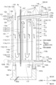
図2は、一実施形態のタービン静翼100の模式的な内部断面図であり、翼型部のキャンバーラインに沿った断面を表している。
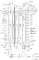
図3は、他の実施形態のタービン静翼100の模式的な内部断面図であり、翼型部のキャンバーラインに沿った断面を表している。
図4は、さらに他の実施形態のタービン静翼100の模式的な内部断面図であり、翼型部のキャンバーラインに沿った断面を表している。
FIG. 2 is a schematic internal cross-sectional view of a turbine vane 100 according to one embodiment, showing a cross-section along a camber line of an airfoil portion.
FIG. 3 is a schematic internal cross-sectional view of a turbine stator vane 100 according to another embodiment, showing a cross section taken along the camber line of the airfoil portion.
FIG. 4 is a schematic internal cross-sectional view of a turbine stator vane 100 according to still another embodiment, showing a cross section taken along the camber line of the airfoil portion.
以下、幾つかの実施形態に係るタービン静翼100の構造について説明する。
以下の説明では、第3段静翼33の構造について説明するが、第1段静翼31、又は、第2段静翼32が第3段静翼33と同様の構造を有していてもよい。また、一実施形態に係るガスタービン1が、第3段静翼33よりも軸方向下流側にタービン静翼100を有している場合、このタービン静翼100が第3段静翼33と同様の構造を有していてもよい。
Hereinafter, the structure of the turbine vane 100 according to several embodiments will be described.
In the following description, the structure of the third stage stator vane 33 will be described, but the first stage stator vane 31 or the second stage stator vane 32 may have a structure similar to that of the third stage stator vane 33. In addition, when the
図2から図4に示すように、幾つかの実施形態に係るタービン静翼100は、翼体101と、インピンジメントプレート130と、空気配管127とを備えている。
幾つかの実施形態に係る翼体101は、隔壁140によって隔てられた複数の冷却流路111を内部に有する翼型部110、該翼型部110の先端110c側、すなわち径方向外側に設けられる外側シュラウド121、及び、該翼型部110の基端110d側(基端側)、すなわち径方向内側に設けられる内側シュラウド122を含む。なお、以下の説明では、径方向を翼型部110の翼高さ方向、又は単に翼高さ方向とも呼ぶ。また、説明の便宜上、複数の冷却流路111について、翼型部110の前縁110a側から後縁110b側にかけて順に、第1冷却流路111a、第2冷却流路111b、第3冷却流路111c、第4冷却流路111d、及び、第5冷却流路111eと呼ぶ。但し、以下の説明では、各冷却流路111a、111b、111c、111d、111eを区別する必要がない場合には、符号における番号の後のアルファベットの記載を省略して、単に冷却流路111と称することがある。
As shown in FIGS. 2-4 , a turbine vane 100 according to some embodiments includes an
The
幾つかの実施形態に係るタービン静翼100では、第1冷却流路111aと第2冷却流路111bとは、隔壁140によって隔てられ、第2冷却流路111bと第3冷却流路111cとは、隔壁140によって隔てられている。第3冷却流路111cと第4冷却流路111dとは、隔壁140によって隔てられ、第4冷却流路111dと第5冷却流路111eとは、隔壁140によって隔てられている。
In some embodiments of the turbine vane 100, the first cooling passage 111a and the second cooling passage 111b are separated by a
幾つかの実施形態に係るタービン静翼100では、ガスパス面は、幾つかの実施形態に係るタービン静翼100がタービンに配置される場合に、燃焼ガスが接触する面であり、図2から図4に示す外側シュラウド121及び内側シュラウド122の外表面121a、122aに相当する。幾つかの実施形態に係るタービン静翼100では、翼型部110及びシュラウド121、122は、例えば鋳造によって製造されている。
In some embodiments of the turbine vane 100, the gas path surface is a surface that comes into contact with the combustion gas when the turbine vane 100 according to some embodiments is disposed in a turbine, and corresponds to the
図2から図4に示した幾つかの実施形態に係るタービン静翼100には、例えば4つの折返し流路112が形成されている。具体的には、前縁110a側から順に、1つ目の折返し流路112aは、第1冷却流路111aと第2冷却流路111bとを連通し、2つ目の折返し流路112bは、第2冷却流路111bと第3冷却流路111cとを連通する。3つ目の折返し流路112cは、第3冷却流路111cと第4冷却流路111dとを連通し、4つ目の折返し流路112dは、第4冷却流路111dと第5冷却流路111eとを連通する。
In the turbine vane 100 according to some embodiments shown in Figures 2 to 4, for example, four turn-
図2から図4に示した幾つかの実施形態に係るタービン静翼100では、翼型部110の後縁110b近傍には、冷却媒体の流れ方向の上流側で第5冷却流路111eに連通し、下流側が後縁110bの端部に開口する複数の冷却孔113が形成されている。
また、図2及び図3に示した幾つかの実施形態に係るタービン静翼100では、内側シュラウド122には、冷却媒体の流れ方向の上流側で第5冷却流路111eに連通し、下流側が例えば内側シュラウド122の後縁側の端面122cに開口する少なくとも1つの出口通路118が形成されている。
図4に示した実施形態に係るタービン静翼100では、内側シュラウド122には、冷却媒体の流れ方向の上流側で第5冷却流路111eに連通し、下流側が例えば後述する下流リブ161bの後縁側の端面161cに開口する少なくとも1つの出口通路118が形成されている。
図2から図4に示した幾つかの実施形態に係るタービン静翼100では、複数の冷却流路111と、複数の折返し流路112とを含むサーペンタイン流路115が形成されている。
In the turbine vane 100 according to some embodiments shown in Figures 2 to 4, a plurality of
In addition, in the turbine vane 100 according to some embodiments shown in Figures 2 and 3, the
In the turbine vane 100 according to the embodiment shown in FIG. 4, the
In some embodiments of the turbine vane 100 shown in FIGS. 2 to 4 , a
図2から図4に示した幾つかの実施形態に係るタービン静翼100では、外側シュラウド121には、ガスパス面を形成する底部124と、底部124の軸方向及び周方向の両端から翼高さ方向のガスパス面とは反対側に延びる外壁部123とが形成されている。外側シュラウド121には、外壁部123に固定され、複数の貫通孔114(外側インピンジメント孔114o)を有するインピンジメントプレート130が配置されている。
In the turbine vane 100 according to some embodiments shown in Figures 2 to 4, the
外側シュラウド121には、外壁部123で周囲を囲われた第2凹部(すなわち外側シュラウド121の内部空間116)のうち、インピンジメントプレート130と外側シュラウド121の内表面121bとの間の空間と、タービン静翼100の外部(翼型部110の外部)とを連通する、少なくとも一つの外側通路172が形成されている。
図2から図4に示した幾つかの実施形態に係るタービン静翼100では、少なくとも一つの外側通路172は、内部空間116よりも軸方向下流側の後縁側端部125に形成されている。
図2から図4に示した幾つかの実施形態に係るタービン静翼100では、外側通路172の出口端172oは、例えば外側シュラウド121の後縁側の端面125cに開口している。
The
In some embodiments of the turbine vane 100 illustrated in FIGS. 2-4 , at least one
In the turbine vane 100 according to some embodiments shown in FIGS. 2 to 4 , the outlet end 172o of the
図2から図4に示した幾つかの実施形態に係るタービン静翼100では、内側シュラウド122には、内側シュラウド122の内表面122bから翼高さ方向の内側に突出し、前縁110a側に配置された上流リブ161aと後縁110b側に配置された下流リブ161bとが形成されている。
図2に示すタービン静翼100では、上流リブ161aと下流リブ161bの間には、内部空間117を仕切り、複数の貫通孔114(内側インピンジメント孔114i)を有するインピンジメントプレート130が配置されている。なお、図3及び図4に示すタービン静翼100では、インピンジメントプレート130が配置されていない。
In the turbine vane 100 according to some embodiments shown in Figures 2 to 4, the
In the turbine stator vane 100 shown in Fig. 2, an
図2に示すタービン静翼100では、内側シュラウド122には、上流リブ161aと下流リブ161bとの間の第1凹部(すなわち内側シュラウド122の内部空間117)のうち、インピンジメントプレート130と内側シュラウド122の内表面122bとの間の空間と、タービン静翼100の外部(翼型部110の外部)とを連通する、少なくとも1つの内側通路171が形成されている。
図2に示すタービン静翼100では、少なくとも1つの内側通路171は、内部空間117よりも軸方向下流側の後縁側端部126に形成されている。図2では、図示の便宜上、内側通路171と出口通路118とを翼高さ方向にずらして図示しているが、後述する図6で図示したように、内側通路171と出口通路118とが翼高さ方向の同じ位置に形成されていてもよい。
In the turbine vane 100 shown in Figure 2, the
In the turbine stator vane 100 shown in Fig. 2, at least one
図2に示すタービン静翼100では、内側通路171は、翼型部110の内部の空間110iと非連通である。ここで、内側通路171が翼型部110の内部の空間110iと非連通であるということは、内側通路171の直接的な接続先が翼型部110の内部の空間110iではないことを意味する。すなわち、内側通路171が翼型部110の内部の空間110iと非連通であるということは、内側通路171の全ての端部開口(入口端171i及び出口端171o)が翼型部110の内部の空間110iに面していないことを意味する。
なお、幾つかの実施形態において、翼型部110の内部の空間110iは、翼型部110(外側シュラウド121の外表面121aと内側シュラウド122の外表面122aとの間の領域)の内部に形成された空所であり、例えば、サーペンタイン流路115が含まれる。
なお、図3及び図4に示すタービン静翼100では、内側通路171が形成されていない。
In the turbine vane 100 shown in Fig. 2, the
In some embodiments, the
In addition, in the turbine vane 100 shown in FIGS. 3 and 4, the
図2から図4に示した幾つかの実施形態に係るタービン静翼100は、例えば第2冷却流路111b内の翼高さ方向に、翼型部110を貫通する空気配管127を備えている。空気配管127の一端は、内側シュラウド122に支持された保持環162に形成された内部空間117に開口している。保持環162は、内側シュラウド122の上流リブ161aと下流リブ161bを介して、内側シュラウド122に支持されている。
また、保持環162は、例えば底面に流通孔162aを備えている。
2 to 4, the turbine vane 100 according to some embodiments includes an
The retaining
タービン静翼100に供給される冷却媒体には、例えば、圧縮機2から抽気した圧縮空気が利用される。
図2から図4に示した幾つかの実施形態に係るタービン静翼100では、サーペンタイン流路115に供給される冷却媒体は、矢印aで示すように、外部から外側シュラウド121の内部空間116に供給される。冷却媒体は、外側シュラウド121に形成された開口133を介して第1冷却流路111aに流入し、矢印bで示すように、第1冷却流路111a内を翼高さ方向に沿って先端110c側から基端110d側に向かって流れる。その後、第1冷却流路111aに流入した冷却媒体は、矢印c~jで示すように、各折返し流路112及び各冷却流路111を順に流れる。このように、冷却媒体は、翼型部110内で前縁110a側から後縁110b側に向かって、燃焼ガスの主たる流れと同じ方向へ向かって流れる。
The cooling medium supplied to the turbine vanes 100 is, for example, compressed air extracted from the
In the turbine vane 100 according to some embodiments shown in Figures 2 to 4, the cooling medium supplied to the
第5冷却流路111eに流入した冷却媒体は、矢印k1で示すように、後縁110bに開口する複数の冷却孔113から翼型部110の外部の燃焼ガス中に排出される。
また、第5冷却流路111eに流入した冷却媒体は、矢印k2で示すように、出口通路118を介して翼型部110の外部の燃焼ガス中に排出される。
The cooling medium that has flowed into the fifth
Furthermore, the cooling medium that has flowed into the
また、図2から図4に示した幾つかの実施形態に係るタービン静翼100では、外側シュラウド121に配置されたインピンジメントプレート130の複数の貫通孔114を介して、該インピンジメントプレート130よりも径方向外側(先端110c側)の領域内(内部空間116)に外部から供給された冷却媒体が外側シュラウド121の底部124の径方向外側(先端110c側)の内表面121bに吹き付けられる。冷却媒体は、内表面121bをインピンジメント冷却(衝突冷却)している。これにより、外側シュラウド121の底部124を冷却媒体で冷却できる。
In addition, in the turbine vane 100 according to some embodiments shown in Figures 2 to 4, a cooling medium is supplied from the outside to a region (internal space 116) radially outward (tip 110c side) of the
外側シュラウド121の底部124を冷却した冷却媒体は、複数の外側通路172を介して第2凹部(内部空間116)から翼型部110の外部の燃焼ガス中に排出される。
The cooling medium that has cooled the
外側シュラウド121の内部空間116から供給された冷却媒体Acは、空気配管127を介して内側シュラウド122側の保持環162に形成された内部空間117に供給される。
The cooling medium Ac supplied from the
図2に示したタービン静翼100では、一部の冷却媒体Acは、内側シュラウド122に配置されたインピンジメントプレート130の複数の貫通孔114を介して、内側シュラウド122の内表面122bをインピンジメント冷却(衝突冷却)する冷却空気として適用される。
図2に示したタービン静翼100では、残りの冷却媒体Acは、流通孔162aから不図示の段間キャビティに供給され、パージ用空気として、燃焼ガスが段間キャビティへ逆流する現象を防止している。
In the turbine vane 100 shown in FIG. 2 , a portion of the cooling medium Ac is applied as cooling air for impingement cooling (impingement cooling) of the
In the turbine vane 100 shown in FIG. 2, the remaining cooling medium Ac is supplied to an interstage cavity (not shown) through the
図2に示したタービン静翼100では、内側シュラウド122の内表面122bを冷却した冷却媒体Acは、内側通路171を介して第1凹部(内部空間117)から翼型部110の外部の燃焼ガス中に排出される。
In the turbine vane 100 shown in FIG. 2, the cooling medium Ac that cools the
なお、図3及び図4に示すタービン静翼100では、内部空間117に供給された冷却媒体Acは、流通孔162aから不図示の段間キャビティに供給され、パージ用空気として、燃焼ガスが段間キャビティへ逆流する現象を防止している。
In the turbine vane 100 shown in Figures 3 and 4, the cooling medium Ac supplied to the
上述したように、図2から図4に示した幾つかの実施形態に係るタービン静翼100は、翼型部110と、翼型部110の内周側に設けられる内側シュラウド122と、翼型部110の外周側に設けられる外側シュラウド121と、を備える。
図2から図4に示した幾つかの実施形態に係るタービン静翼100では、内側シュラウド122は、内側シュラウド122のガスパス面(外表面122a)を挟んで翼型部110とは反対側の面に形成された第1凹部(内部空間117)を有する。
図2から図4に示した幾つかの実施形態に係るタービン静翼100では、外側シュラウド121は、外側シュラウド121のガスパス面(外表面121a)を挟んで翼型部110とは反対側の面に形成された第2凹部(内部空間116)と、第2凹部(内部空間116)に連通し、且つ、翼型部110の内部の空間110iと非連通である少なくとも1つの外側通路172とを有する。
As described above, the turbine vane 100 according to some embodiments shown in Figures 2 to 4 includes an
In the turbine vane 100 according to some embodiments shown in Figures 2 to 4, the
In the turbine vane 100 according to some embodiments shown in Figures 2 to 4, the
ここで、外側通路172が翼型部110の内部の空間110iと非連通であるということは、外側通路172の直接的な接続先が翼型部110の内部の空間110iではないことを意味する。すなわち、外側通路172が翼型部110の内部の空間110iと非連通であるということは、外側通路172の全ての端部開口(入口端172i及び出口端172o)が翼型部110の内部の空間110iに面していないことを意味する。
Here, the fact that the
発明者らが、ガスタービン1の実機における燃焼ガスの温度を測定したところ、第3段静翼33において、ハブ側の燃焼ガス温度が事前の想定よりも低いことが判明し、第3段静翼33における内側シュラウド122のメタル温度も事前の想定よりも低いことが判明した。タービン静翼100のメタル温度が事前に想定していた温度よりも低いと、ガスタービン1の効率低下を招くため、タービン静翼100のメタル温度は、事前に想定していた温度に近い温度であることが望まれる。
When the inventors measured the temperature of the combustion gas in an
そこで、幾つかの実施形態のタービン静翼100では、外側通路172の数が、内側通路171の数よりも多くなるようにしている。
よって、内側シュラウド122の冷却能力を外側シュラウド121の冷却能力よりも抑制できるので、内側シュラウド122の過剰冷却を抑制して、タービン静翼100の冷却を適切化できる。これにより、タービン効率を向上できる
Therefore, in some embodiments of the turbine vane 100 , the number of
Therefore, the cooling capacity of the
より具体的には、幾つかの実施形態では、次の(A)、(B)、又は(C)のいずれかの条件を満たすようにタービン静翼100を構成するとよい。
(A)内側シュラウド122は、内側通路171を有していない。
(B)内側シュラウド122は、内側通路171を1つ有しており、上記1つの内側通路171の出口端171oの断面積Siは、上記少なくとも1つの外側通路172の出口端172oの断面積Soの合計ΣSoよりも小さい。
(C)内側シュラウド122は、内側通路171を2つ以上有しており、内側通路171同士の間隔Piを内側通路171の径Diで除した値(Pi/Di)は、外側通路172同士の間隔Poを外側通路172の径Doで除した値(Po/Do)よりも大きい。
More specifically, in some embodiments, the turbine vane 100 may be configured to satisfy any one of the following conditions (A), (B), or (C).
(A) The
(B) The
(C) The
上記条件(A)について説明する。
上記条件(A)は、例えば図3及び図4に示すように、内部空間117にインピンジメントプレート130が配置されておらず、タービン静翼100に内側通路171が形成されておらず、内側シュラウド122の内表面122bをインピンジメント冷却していない場合が該当する。
図3及び図4に示すタービン静翼100では、内側シュラウド122の内表面122bをインピンジメント冷却しないので、内側シュラウド122の冷却能力を外側シュラウド121の冷却能力よりも抑制できる。これにより、内側シュラウド122の過剰冷却を抑制して、タービン静翼100の冷却を適切化でき、タービン効率を向上できる。
The above condition (A) will now be described.
The above condition (A) corresponds to a case where, for example, as shown in Figures 3 and 4, an
3 and 4, the
上記条件(B)について説明する。
上記条件(B)は、例えば図2に示すように、内部空間117にインピンジメントプレート130が配置されており、タービン静翼100に内側通路171が形成されており、内側シュラウド122の内表面122bをインピンジメント冷却可能である場合に適用される条件である。
上記条件(B)のように、内側シュラウド122が内側通路171を1つ有していて、この1つの内側通路171の出口端171oの断面積Siが、上記少なくとも1つの外側通路172の出口端172oの断面積Soの合計ΣSoよりも小さければ、内側通路171における冷却媒体の流通量を全ての外側通路172における冷却媒体の流通量の合計量よりも抑制できる。これにより、内側シュラウドの冷却能力を外側シュラウドの冷却能力よりも抑制できるので、内側シュラウドの過剰冷却を抑制して、タービン静翼の冷却を適切化できる。よって、タービン効率を向上できる。
The above condition (B) will now be described.
The above condition (B) is a condition that is applied when, for example, as shown in FIG. 2, an
As in the above condition (B), if the
上記条件(C)について説明する。
上記条件(C)は、例えば図2に示すように、内部空間117にインピンジメントプレート130が配置されており、タービン静翼100に内側通路171が形成されており、内側シュラウド122の内表面122bをインピンジメント冷却可能である場合に適用される条件である。
図5は、図2から図4に示したタービン静翼100における外側シュラウド121の後縁側の端面125cを下流側から見た図である。
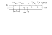
図6は、図2に示したタービン静翼100における内側シュラウド122の後縁側の端面122cを下流側から見た図である。
上記条件(C)のように、内側シュラウド122が内側通路171を2つ以上有していて、内側通路171同士の間隔Piを内側通路171の径Diで除した値(Pi/Di)が、外側通路172同士の間隔Poを外側通路172の径Doで除した値(Po/Do)よりも大きければ、全ての内側通路171における冷却媒体の流通量の合計量を全ての外側通路172における冷却媒体の流通量の合計量よりも抑制できる。これにより、内側シュラウド122の冷却能力を外側シュラウド121の冷却能力よりも抑制できるので、内側シュラウド122の過剰冷却を抑制して、タービン静翼100の冷却を適切化できる。よって、タービン効率を向上できる。
The above condition (C) will now be described.
The above condition (C) is a condition that is applied when, for example, as shown in FIG. 2, an
FIG. 5 is a view of the
FIG. 6 is a view of the
As in the above condition (C), if the
すなわち、幾つかの実施形態では、次の(A)、(B)、又は(C)のいずれかの条件を満たすようにタービン静翼100を構成することで、内側シュラウド122の冷却能力を外側シュラウド121の冷却能力よりも抑制できるので、内側シュラウド122の過剰冷却を抑制して、タービン静翼100の冷却を適切化できる。これにより、タービン効率を向上できる。
In other words, in some embodiments, by configuring the turbine vane 100 to satisfy any one of the following conditions (A), (B), or (C), the cooling capacity of the
幾つかの実施形態では、内側通路171の出口端171oの断面積Siの合計値ΣSiを内側シュラウド122のガスパス面(外表面122a)の面積Sigと内側シュラウド122の後縁側の端面122cの面積Sitとの合計値で除した値(ΣSi/(Sig+Sit))は、外側通路172の出口端172oの断面積Soの合計値ΣSoを外側シュラウド121のガスパス面(外表面121a)の面積Sogと外側シュラウド121の後縁側の端面125cの面積Sotとの合計値で除した値(ΣSo/(Sog+Sot))よりも小さいとよい。
この場合、ガスパス面(外表面121a、122a)の面積(Sog、Sig)とシュラウド121、122の後縁側の端面125c、122cの面積(Sot、Sit)との合計面積についての単位面積当たりで比較すると、内側通路171を流通する冷却媒体の流量は、外側通路172を流通する冷却媒体の流量よりも少なくなる。これにより、内側シュラウド122の冷却能力を外側シュラウド121の冷却能力よりも抑制できるので、内側シュラウド122の過剰冷却を抑制して、タービン静翼100の冷却を適切化できる。
In some embodiments, the value (ΣSi/(Sig+Sit)) obtained by dividing the total value ΣSi of the cross-sectional areas Si of the outlet ends 171o of the
In this case, when comparing the total area ( Sog, Sig ) of the gas path surfaces (
幾つかの実施形態では、内側通路171の出口端171oの内、内側シュラウド122の後縁側の端面122cに開口した出口端171oの断面積Si1の合計値ΣSi1を内側シュラウド122の後縁側の端面122cの面積Sitで除した値(ΣSi1/Sit)は、外側通路172の出口端172oの内、外側シュラウド121の後縁側の端面125cに開口した出口端172oの断面積So1の合計値ΣSo1を外側シュラウド121の後縁側の端面125cの面積Sotで除した値(ΣSo1/Sot)よりも小さいとよい。
この場合、シュラウド121、122の後縁側の端面125c、122cの単位面積当たりで比較すると、内側通路171を流通する冷却媒体の流量は、外側通路172を流通する冷却媒体の流量よりも少なくなる。これにより、内側シュラウド122の冷却能力を外側シュラウド121の冷却能力よりも抑制できるので、内側シュラウド122の過剰冷却を抑制して、タービン静翼100の冷却を適切化できる。
In some embodiments, the value (ΣSi1/Sit) obtained by dividing the sum ΣSi1 of the cross-sectional areas Si1 of the outlet ends 171o of the
In this case, when compared per unit area of the end faces 125c, 122c on the trailing edge sides of the
幾つかの実施形態では、内側シュラウド122をインピンジメント冷却するための内側インピンジメント孔114iの開口密度は、外側シュラウド121をインピンジメント冷却するための外側インピンジメント孔114oの開口密度よりも小さいとよい。
ここで、内側インピンジメント孔114iの開口密度は、内側インピンジメント孔114iの開口面積の合計値を内側シュラウド122に配置されたインピンジメントプレート130の面積で除した値である。
同様に、外側インピンジメント孔114oの開口密度は、外側インピンジメント孔114oの開口面積の合計値を外側シュラウド121に配置されたインピンジメントプレート130の面積で除した値である。
これにより、内側シュラウド122の冷却能力を外側シュラウド121の冷却能力よりも抑制できるので、内側シュラウド122の過剰冷却を抑制して、タービン静翼100の冷却を適切化できる。
In some embodiments, the opening density of the inner impingement holes 114 i for impingement cooling the
Here, the opening density of the inner impingement holes 114 i is a value obtained by dividing the total value of the opening area of the inner impingement holes 114 i by the area of the
Similarly, the opening density of the outer impingement holes 114o is the sum of the opening areas of the outer impingement holes 114o divided by the area of the
This allows the cooling capacity of the
なお、上述した、「内側シュラウド122をインピンジメント冷却するための内側インピンジメント孔114iの開口密度は、外側シュラウド121をインピンジメント冷却するための外側インピンジメント孔114oの開口密度よりも小さい」との文言には、内側シュラウド122をインピンジメント冷却するための内側インピンジメント孔114iの開口密度がゼロ、すなわち、図3又は図4に示すように、内側インピンジメント孔114iが形成されたインピンジメントプレート130が取り付けられていない場合も含まれる。
この場合には、内側シュラウド122のインピンジメント冷却をしないことにより、内側シュラウド122の過剰冷却を抑制して、タービン静翼100の冷却を適切化できる。
In addition, the above-mentioned phrase "the opening density of the inner impingement holes 114i for impingement cooling the
In this case, by not performing impingement cooling of the
(遮熱コーティングについて)
図2から図4に示すタービン静翼100では、翼型部110や外側シュラウド121のガスパス面(外表面121a)等に、遮熱コーティング180が施されているとよい。
図2から図4に示すタービン静翼100における遮熱コーティング180の施工範囲は、例えば、翼型部110の表面110s、外側シュラウド121の外表面121a、翼型部110の表面110sと外側シュラウド121の外表面121aとを接続するフィレット部175の表面175s、翼型部110の表面110sと内側シュラウド122の外表面122aとを接続するフィレット部175の表面175sである(図2参照)。
(About thermal barrier coating)
In the turbine vane 100 shown in FIGS. 2 to 4, a
The application range of the
内側シュラウド122の冷却能力に余裕がある場合、施工コストが比較的高い遮熱コーティング180の施工範囲を狭めることでタービン静翼100の製造コストを抑制することが考えられる。
すなわち、上述したように冷却媒体による内側シュラウド122の冷却を抑制すると、内側シュラウド122の温度は、ハブ側の燃焼ガス温度に比較的近い温度となる。このような場合には、内側シュラウド122の外表面122aに遮熱コーティング180を施工して、内側シュラウド122の温度をハブ側の燃焼ガス温度よりも下げようとする必要性が乏しくなる。
When the cooling capacity of the
That is, when the cooling of the
そこで、図2から図4に示すタービン静翼100では、内側シュラウド122の外表面122aには、遮熱コーティング180を施さないこととした。なお、内側シュラウド122の外表面122aの全部ではなく一部に遮熱コーティング180が施されていてもよい。
ここで、内側シュラウド122の外表面122aには、翼型部110の表面110sと内側シュラウド122の外表面122aとを接続するフィレット部175の表面175sは含まれない。
2 to 4, the
Here, the
このように、幾つかの実施形態では、内側シュラウド122のガスパス面(外表面122a)に施工された遮熱コーティング180の施工面積Sicを内側シュラウド122のガスパス面(外表面122a)の面積Sigで除した値(Sic/Sig)は、外側シュラウド121のガスパス面(外表面121a)に施工された遮熱コーティング180の施工面積Socを外側シュラウド121のガスパス面(外表面121a)の面積Sogで除した値(Soc/Sog)よりも小さくてもよい。
なお、上述した、値(Sic/Sig)が値(Soc/Sog)よりも小さいことには、内側シュラウド122のガスパス面(外表面122a)に施工された遮熱コーティング180の施工面積Sicがゼロの場合も含まれる。
すなわち、上述したように、内側シュラウド122は、内側シュラウド122のガスパス面(外表面122a)に遮熱コーティング180が施工されていなくてもよい。
このように、内側シュラウド122のガスパス面(外表面122a)における遮熱コーティングの施工範囲を狭めることでタービン静翼100の製造コストを抑制できる。
Thus, in some embodiments, the value (Sic/Sig) obtained by dividing the application area Sic of the
In addition, the above-mentioned value (Sic/Sig) being smaller than the value (Soc/Sog) also includes the case where the application area Sic of the
That is, as described above, the
In this manner, by narrowing the application area of the thermal barrier coating on the gas path surface (
図2から図4に示すタービン静翼100では、内側シュラウド122は、翼型部110の内部の空間110iと連通し、第1凹部(内部空間117)に非連通である出口通路118を有していてもよい。
これにより、翼型部110の内部の空間110iであるサーペンタイン流路115に冷却媒体が供給されている場合、この冷却媒体を出口通路118を介してタービン静翼100の外部に排出できる。
なお、上述した翼型部110の内部の空間110iは、サーペンタイン流路115以外に翼型部110の内部に形成された冷却媒体の流路であってもよい。
In the turbine vane 100 shown in Figures 2 to 4, the
As a result, when a cooling medium is supplied to the
The
幾つかの実施形態では、図2から図4に示すタービン静翼100は、上述したように、タービン3段静翼(第3段静翼33)であるとよい。
これにより、上述したように、第3段静翼33におけるハブ側の燃焼ガス温度が事前の想定よりも低く、第3段静翼33の内側シュラウド122のメタル温度も事前の想定よりも低い場合に、内側シュラウド122の過剰冷却を抑制して、タービン静翼100(第3段静翼33)の冷却を適切化できる。
In some embodiments, the turbine vane 100 shown in Figures 2-4 may be a turbine stage three vane (stage three vane 33), as described above.
As a result, as described above, when the combustion gas temperature on the hub side of the third stage vane 33 is lower than previously assumed and the metal temperature of the
本開示は上述した実施形態に限定されることはなく、上述した実施形態に変形を加えた形態や、これらの形態を適宜組み合わせた形態も含む。
例えば、上述した幾つかの実施形態では、内側通路171の出口端171oは、内側シュラウド122の後縁側の端面122cに形成されているが、少なくとも一部の出口端171oは、内側シュラウド122の外表面122aに形成されていてもよい。
The present disclosure is not limited to the above-described embodiments, and includes modifications to the above-described embodiments and appropriate combinations of these modifications.
For example, in some of the embodiments described above, the outlet end 171o of the
例えば、上述した幾つかの実施形態では、外側通路172の出口端172oは、外側シュラウド121の後縁側の端面125cに形成されているが、少なくとも一部の出口端172oは、外側シュラウド121の外表面121aに形成されていてもよい。
For example, in some of the embodiments described above, the outlet end 172o of the
例えば、上述した幾つかの実施形態では、出口通路118の出口端118oは、内側シュラウド122の後縁側の端面122c、又は、下流リブ161bの後縁側の端面161cに形成されているが、少なくとも一部の出口端118oは、内側シュラウド122の外表面122aに形成されていてもよい。
For example, in some of the embodiments described above, the outlet end 118o of the
上記各実施形態に記載の内容は、例えば以下のように把握される。
(1)本開示の少なくとも一実施形態に係るタービン静翼100は、翼型部110と、翼型部110の内周側に設けられる内側シュラウド122と、翼型部110の外周側に設けられる外側シュラウド121と、を備える。内側シュラウド122は、内側シュラウド122のガスパス面(外表面122a)を挟んで翼型部110とは反対側の面に形成された第1凹部(内部空間117)を有する。外側シュラウド121は、外側シュラウド121のガスパス面(外表面121a)を挟んで翼型部110とは反対側の面に形成された第2凹部(内部空間116)と、第2凹部(内部空間116)に連通し、且つ、翼型部110の内部の空間110i(例えばサーペンタイン流路115)と非連通である少なくとも1つの外側通路172とを有する。外側通路172の数は、内側シュラウド122において第1凹部(内部空間117)に連通し、且つ、翼型部110の内部の空間110i(例えばサーペンタイン流路115)と非連通である内側通路171の数よりも多い。
The contents described in each of the above embodiments can be understood, for example, as follows.
(1) A turbine vane 100 according to at least one embodiment of the present disclosure includes an
上記(1)の構成によれば、内側シュラウド122の冷却能力を外側シュラウド121の冷却能力よりも抑制できるので、内側シュラウド122の過剰冷却を抑制して、タービン静翼100の冷却を適切化できる。これにより、タービン効率を向上できる。
According to the configuration (1) above, the cooling capacity of the
(2)幾つかの実施形態では、上記(1)の構成において、次の(A)、(B)、又は(C)のいずれかの条件を満たすとよい。
(A)内側シュラウド122は、内側通路171を有していない。
(B)内側シュラウド122は、内側通路171を1つ有しており、上記1つの内側通路171の出口端171oの断面積Siは、上記少なくとも1つの外側通路172の出口端172oの断面積Soの合計ΣSoよりも小さい。
(C)内側シュラウド122は、内側通路171を2つ以上有しており、内側通路171同士の間隔Piを内側通路171の径Diで除した値(Pi/Di)は、外側通路172同士の間隔Poを外側通路172の径Doで除した値(Po/Do)よりも大きい。
(2) In some embodiments, in the configuration of (1) above, it is preferable that any one of the following conditions (A), (B), or (C) is satisfied.
(A) The
(B) The
(C) The
上記(2)の構成によれば、上記(A)、(B)、又は(C)のいずれかの条件を満たせば、内側シュラウド122の冷却能力を外側シュラウド121の冷却能力よりも抑制できるので、内側シュラウド122の過剰冷却を抑制して、タービン静翼100の冷却を適切化できる。これにより、タービン効率を向上できる。
According to the configuration of (2) above, if any of the conditions (A), (B), or (C) above is satisfied, the cooling capacity of the
(3)幾つかの実施形態では、上記(2)の構成において、内側通路171の出口端171oの断面積Siの合計値ΣSiを内側シュラウド122のガスパス面(外表面122a)の面積Sigと内側シュラウド122の後縁側の端面122cの面積Sitとの合計値で除した値(ΣSi/(Sig+Sit))は、外側通路172の出口端172oの断面積Soの合計値ΣSoを外側シュラウド121のガスパス面(外表面121a)の面積Sogと外側シュラウド121の後縁側の端面125cの面積Sotとの合計値で除した値(ΣSo/(Sog+Sot))よりも小さいとよい。
(3) In some embodiments, in the configuration of (2) above, the value (ΣSi/(Sig+Sit)) obtained by dividing the total cross-sectional area Si of the outlet end 171o of the
上記(3)の構成によれば、ガスパス面(外表面121a、122a)の面積(Sog、Sig)とシュラウド121、122の後縁側の端面125c、122cの面積(Sot、Sit)との合計面積についての単位面積当たりで比較すると、内側通路171を流通する冷却媒体の流量は、外側通路172を流通する冷却媒体の流量よりも少ない。これにより、内側シュラウド122の冷却能力を外側シュラウド121の冷却能力よりも抑制できるので、内側シュラウド122の過剰冷却を抑制して、タービン静翼100の冷却を適切化できる。
According to the above configuration (3), when comparing per unit area the total area (Sog, Sig) of the gas path surfaces (
(4)幾つかの実施形態では、上記(2)又は(3)の構成において、内側通路171の出口端171oの内、内側シュラウド122の後縁側の端面122cに開口した出口端171oの断面積Si1の合計値ΣSi1を内側シュラウド122の後縁側の端面122cの面積Sitで除した値(ΣSi1/Sit)は、外側通路172の出口端172oの内、外側シュラウド121の後縁側の端面125cに開口した出口端172oの断面積So1の合計値ΣSo1を外側シュラウド121の後縁側の端面125cの面積Sotで除した値(ΣSo1/Sot)よりも小さいとよい。
(4) In some embodiments, in the configuration of (2) or (3) above, it is preferable that the value (ΣSi1/Sit) obtained by dividing the sum ΣSi1 of the cross-sectional areas Si1 of the outlet ends 171o of the
上記(4)の構成によれば、シュラウド121、122の後縁側の端面125c、122cの単位面積当たりで比較すると、内側通路171を流通する冷却媒体の流量は、外側通路172を流通する冷却媒体の流量よりも少ない。これにより、内側シュラウド122の冷却能力を外側シュラウド121の冷却能力よりも抑制できるので、内側シュラウド122の過剰冷却を抑制して、タービン静翼100の冷却を適切化できる。
According to the configuration of (4) above, when compared per unit area of the trailing edge end faces 125c, 122c of the
(5)幾つかの実施形態では、上記(1)乃至(4)の何れかの構成において、内側シュラウド122をインピンジメント冷却するための内側インピンジメント孔114iの開口密度は、外側シュラウド121をインピンジメント冷却するための外側インピンジメント孔114oの開口密度よりも小さいとよい。
(5) In some embodiments, in any of the configurations (1) to (4) above, the opening density of the inner impingement holes 114i for impingement cooling the
上記(5)の構成によれば、内側シュラウド122の冷却能力を外側シュラウド121の冷却能力よりも抑制できるので、内側シュラウド122の過剰冷却を抑制して、タービン静翼100の冷却を適切化できる。
According to the configuration (5) above, the cooling capacity of the
(6)幾つかの実施形態では、上記(5)の構成において、内側シュラウドには、内側インピンジメント孔114iが形成されたインピンジメントプレート130が取り付けられていなくてもよい。
(6) In some embodiments, in the configuration of (5) above, the
上記(6)の構成によれば、内側シュラウド122のインピンジメント冷却をしないことにより、内側シュラウド122の過剰冷却を抑制して、タービン静翼100の冷却を適切化できる。
According to the above configuration (6), by not performing impingement cooling of the
(7)幾つかの実施形態では、上記(1)乃至(6)の何れかの構成において、内側シュラウド122のガスパス面(外表面122a)に施工された遮熱コーティング180の施工面積Sicを内側シュラウド122のガスパス面(外表面122a)の面積Sigで除した値(Sic/Sig)は、外側シュラウド121のガスパス面(外表面121a)に施工された遮熱コーティング180の施工面積Socを外側シュラウド121のガスパス面(外表面121a)の面積Sogで除した値(Soc/Sog)よりも小さくてもよい。
(7) In some embodiments, in any of the configurations (1) to (6) above, the value (Sic/Sig) obtained by dividing the application area Sic of the
内側シュラウド122の冷却能力に余裕がある場合、施工コストが比較的高い遮熱コーティングの施工範囲を狭めることでタービン静翼100の製造コストを抑制することが考えられる。
上記(7)の構成によれば、内側シュラウド122のガスパス面(外表面122a)における遮熱コーティング180の施工範囲を狭めることでタービン静翼100の製造コストを抑制できる。
When the cooling capacity of the
According to the above configuration (7), the application area of the
(8)幾つかの実施形態では、上記(7)の構成において、内側シュラウド122は、内側シュラウド122のガスパス面(外表面122a)に遮熱コーティング180が施工されていなくてもよい。
(8) In some embodiments, in the configuration of (7) above, the
内側シュラウドの冷却能力に余裕がある場合、施工コストが比較的高い遮熱コーティング180の施工範囲を狭めることでタービン静翼100の製造コストを抑制することが考えられる。
上記(8)の構成によれば、内側シュラウド122のガスパス面(外表面122a)に遮熱コーティング180を施工しないことでタービン静翼100の製造コストを抑制できる。
When the cooling capacity of the inner shroud is sufficient, it is possible to reduce the manufacturing cost of the turbine vane 100 by narrowing the application area of the
According to the above configuration (8), the
(9)幾つかの実施形態では、上記(1)乃至(8)の何れかの構成において、内側シュラウド122は、翼型部110の内部の空間110i(例えばサーペンタイン流路115)と連通し、第1凹部(内部空間117)に非連通である出口通路118を有していてもよい。
(9) In some embodiments, in any of the configurations (1) to (8) above, the
上記(9)の構成によれば、翼型部110の内部の空間110i(例えばサーペンタイン流路115)に冷却媒体が供給されている場合、この冷却媒体を出口通路118を介してタービン静翼100の外部に排出できる。
According to the configuration (9) above, when a cooling medium is supplied to the
(10)幾つかの実施形態では、上記(9)の構成において、出口通路118が連通する翼型部110の内部の空間110iは、翼型部110を冷却するためのサーペンタイン流路115であってもよい。
(10) In some embodiments, in the configuration of (9) above, the
上記(10)の構成によれば、翼型部110を冷却するためのサーペンタイン流路115に供給された冷却媒体を出口通路118を介してタービン静翼100の外部に排出できる。
According to the above configuration (10), the cooling medium supplied to the
(11)本開示の少なくとも一実施形態に係るタービン静翼100は、翼型部110と、翼型部110の内周側に設けられる内側シュラウド122と、翼型部110の外周側に設けられる外側シュラウド121と、を備える。内側シュラウド122をインピンジメント冷却するための内側インピンジメント孔114iの開口密度は、外側シュラウド121をインピンジメント冷却するための外側インピンジメント孔114oの開口密度よりも小さい。
(11) A turbine vane 100 according to at least one embodiment of the present disclosure includes an
上記(11)の構成によれば、内側シュラウド122の冷却能力を外側シュラウド121の冷却能力よりも抑制できるので、内側シュラウド122の過剰冷却を抑制して、タービン静翼100の冷却を適切化できる。これにより、タービン効率を向上できる。
According to the configuration (11) above, the cooling capacity of the
(12)幾つかの実施形態では、上記(1)乃至(11)の何れかの構成において、上記タービン静翼100は、タービン3段静翼(第3段静翼33)であるとよい。 (12) In some embodiments, in any of the configurations (1) to (11) above, the turbine vane 100 may be a turbine three-stage vane (third-stage vane 33).
上記(12)の構成によれば、タービン3段静翼(第3段静翼33)におけるハブ側の燃焼ガス温度が事前の想定よりも低く、タービン3段静翼(第3段静翼33)の内側シュラウド122のメタル温度も事前の想定よりも低い場合に、内側シュラウド122の過剰冷却を抑制して、タービン静翼100(第3段静翼33)の冷却を適切化できる。
According to the above configuration (12), when the combustion gas temperature on the hub side of the turbine third-stage stator vane (third-stage stator vane 33) is lower than previously assumed, and the metal temperature of the
1 ガスタービン
33 第3段静翼(タービン3段静翼)
100 タービン静翼
110 翼型部
110i 空間
114 貫通孔
114i 内側インピンジメント孔
114o 外側インピンジメント孔
116 内部空間(第2凹部)
117 内部空間(第1凹部)
118 出口通路
121 外側シュラウド
121a 外表面
122 内側シュラウド
122a 外表面
122c 端面
125c 端面
130 インピンジメントプレート
171 内側通路
171o 出口端
172 外側通路
172o 出口端
180 遮熱コーティング
1 Gas turbine 33 Third stage vane (turbine third stage vane)
100
117 Internal space (first recess)
118
Claims (12)
前記翼型部の内周側に設けられる内側シュラウドと、
前記翼型部の外周側に設けられる外側シュラウドと、
を備え、
前記内側シュラウドは、前記内側シュラウドのガスパス面を挟んで前記翼型部とは反対側の面に形成された第1凹部を有し、
前記外側シュラウドは、前記外側シュラウドのガスパス面を挟んで前記翼型部とは反対側の面に形成された第2凹部と、前記第2凹部に連通し、且つ、前記翼型部の内部の空間と非連通である少なくとも1つの外側通路とを有し、
前記外側通路の数は、前記内側シュラウドにおいて前記第1凹部に連通し、且つ、前記翼型部の内部の空間と非連通である内側通路の数よりも多く、
前記内側シュラウドのガスパス面に施工された遮熱コーティングの施工面積Sicを前記内側シュラウドの前記ガスパス面の面積Sigで除した値(Sic/Sig)は、前記外側シュラウドのガスパス面に施工された遮熱コーティングの施工面積Socを前記外側シュラウドの前記ガスパス面の面積Sogで除した値(Soc/Sog)よりも小さい
タービン静翼。 An airfoil portion;
An inner shroud provided on an inner circumferential side of the airfoil portion;
an outer shroud provided on an outer circumferential side of the airfoil portion;
Equipped with
the inner shroud has a first recess formed on a surface of the inner shroud opposite to the airfoil portion across a gas path surface of the inner shroud,
the outer shroud has a second recess formed on a surface of the outer shroud opposite to the airfoil portion across a gas path surface thereof, and at least one outer passage communicating with the second recess and not communicating with a space inside the airfoil portion,
the number of the outer passages is greater than the number of inner passages that communicate with the first recess in the inner shroud and that are not communicated with a space inside the airfoil portion,
A value (Sic/Sig) obtained by dividing an application area Sic of the thermal barrier coating applied to the gas path surface of the inner shroud by an area Sig of the gas path surface of the inner shroud is smaller than a value (Soc/Sog) obtained by dividing an application area Soc of the thermal barrier coating applied to the gas path surface of the outer shroud by an area Sog of the gas path surface of the outer shroud.
Turbine vanes.
(A)前記内側シュラウドは、前記内側通路を有していない。
(B)前記内側シュラウドは、前記内側通路を1つ有しており、
前記1つの前記内側通路の出口端の断面積Siは、前記少なくとも1つの外側通路の出口端の断面積Soの合計ΣSoよりも小さい。
(C)前記内側シュラウドは、前記内側通路を2つ以上有しており、
前記内側通路同士の間隔Piを前記内側通路の径Diで除した値(Pi/Di)は、前記外側通路同士の間隔Poを前記外側通路の径Doで除した値(Po/Do)よりも大きい。 The turbine vane according to claim 1 , which satisfies any one of the following conditions (A), (B), or (C):
(A) The inner shroud does not have the inner passage.
(B) the inner shroud has one of the inner passages;
A cross-sectional area Si of the outlet end of the one inner passage is smaller than the sum ΣSo of cross-sectional areas So of the outlet ends of the at least one outer passage.
(C) the inner shroud has two or more of the inner passages,
A value (Pi/Di) obtained by dividing the interval Pi between the inner passages by the diameter Di of the inner passage is greater than a value (Po/Do) obtained by dividing the interval Po between the outer passages by the diameter Do of the outer passage.
請求項2に記載のタービン静翼。 3. The turbine vane according to claim 2, wherein a value (ΣSi/(Sig+Sit)) obtained by dividing a total value ΣSi of cross-sectional areas Si of the outlet ends of the inner passages by a total value of an area Sig of the gas path surface of the inner shroud and an area Sit of an end face on a trailing edge of the inner shroud is smaller than a value (ΣSo/(Sog+Sot)) obtained by dividing a total value ΣSo of cross-sectional areas So of the outlet ends of the outer passages by a total value of an area Sog of the gas path surface of the outer shroud and an area Sot of the end face on a trailing edge of the outer shroud.
請求項2又は3に記載のタービン静翼。 4. The turbine vane according to claim 2 or 3, wherein a value (ΣSi1/Sit) obtained by dividing a sum ΣSi1 of cross-sectional areas Si1 of the outlet ends of the inner passages that open into an end face on a trailing edge of the inner shroud by an area Sit of the end face on the trailing edge of the inner shroud is smaller than a value (ΣSo1/Sot ) obtained by dividing a sum ΣSo1 of cross-sectional areas So1 of the outlet ends of the outer passages that open into an end face on a trailing edge of the outer shroud by an area Sot of the end face on the trailing edge of the outer shroud.
請求項1乃至3の何れか一項に記載のタービン静翼。 4. The turbine vane according to claim 1, wherein an opening density of inner impingement holes for impingement cooling the inner shroud is smaller than an opening density of outer impingement holes for impingement cooling the outer shroud.
請求項5に記載のタービン静翼。 The turbine vane according to claim 5 , wherein the inner shroud is not provided with an impingement plate having the inner impingement holes formed therein.
請求項1乃至3の何れか一項に記載のタービン静翼。 The turbine vane according to claim 1 , wherein the inner shroud has no thermal barrier coating applied to the gas path surface of the inner shroud.
請求項1至3の何れか一項に記載のタービン静翼。 The turbine vane according to claim 1 , wherein the inner shroud has an outlet passage that communicates with a space inside the airfoil portion and does not communicate with the first recess.
請求項8に記載のタービン静翼。 9. The turbine vane according to claim 8 , wherein a space inside the airfoil portion, which communicates with the outlet passage, is a serpentine flow passage for cooling the airfoil portion.
前記翼型部の内周側に設けられる内側シュラウドと、
前記翼型部の外周側に設けられる外側シュラウドと、
を備え、
前記内側シュラウドをインピンジメント冷却するための内側インピンジメント孔の開口密度は、前記外側シュラウドをインピンジメント冷却するための外側インピンジメント孔の開口密度よりも小さく、
前記内側シュラウドのガスパス面に施工された遮熱コーティングの施工面積Sicを前記内側シュラウドの前記ガスパス面の面積Sigで除した値(Sic/Sig)は、前記外側シュラウドのガスパス面に施工された遮熱コーティングの施工面積Socを前記外側シュラウドの前記ガスパス面の面積Sogで除した値(Soc/Sog)よりも小さい
タービン静翼。 An airfoil portion;
An inner shroud provided on an inner circumferential side of the airfoil portion;
an outer shroud provided on an outer circumferential side of the airfoil portion;
Equipped with
an opening density of inner impingement holes for impingement cooling the inner shroud is less than an opening density of outer impingement holes for impingement cooling the outer shroud;
A value (Sic/Sig) obtained by dividing an application area Sic of the thermal barrier coating applied to the gas path surface of the inner shroud by an area Sig of the gas path surface of the inner shroud is smaller than a value (Soc/Sog) obtained by dividing an application area Soc of the thermal barrier coating applied to the gas path surface of the outer shroud by an area Sog of the gas path surface of the outer shroud.
Turbine vanes.
請求項10に記載のタービン静翼。The turbine vane of claim 10.
請求項1乃至3の何れか一項に記載のタービン静翼。 The turbine vane according to claim 1 , wherein the turbine vane is a three-stage turbine vane.
Applications Claiming Priority (3)
| Application Number | Priority Date | Filing Date | Title |
|---|---|---|---|
| JP2021193277 | 2021-11-29 | ||
| JP2021193277 | 2021-11-29 | ||
| PCT/JP2022/042830 WO2023095721A1 (en) | 2021-11-29 | 2022-11-18 | Turbine stator vane |
Publications (3)
| Publication Number | Publication Date |
|---|---|
| JPWO2023095721A1 JPWO2023095721A1 (en) | 2023-06-01 |
| JPWO2023095721A5 JPWO2023095721A5 (en) | 2024-06-26 |
| JP7674511B2 true JP7674511B2 (en) | 2025-05-09 |
Family
ID=86539691
Family Applications (1)
| Application Number | Title | Priority Date | Filing Date |
|---|---|---|---|
| JP2023563659A Active JP7674511B2 (en) | 2021-11-29 | 2022-11-18 | Turbine vanes |
Country Status (5)
| Country | Link |
|---|---|
| US (1) | US12385403B2 (en) |
| JP (1) | JP7674511B2 (en) |
| KR (1) | KR20240055099A (en) |
| CN (1) | CN118103583A (en) |
| WO (1) | WO2023095721A1 (en) |
Citations (8)
| Publication number | Priority date | Publication date | Assignee | Title |
|---|---|---|---|---|
| US4012167A (en) | 1975-10-14 | 1977-03-15 | United Technologies Corporation | Turbomachinery vane or blade with cooled platforms |
| JP2001254604A (en) | 2000-03-08 | 2001-09-21 | Mitsubishi Heavy Ind Ltd | Gas turbine cooling stationary vane |
| JP2004060638A (en) | 2002-07-25 | 2004-02-26 | Mitsubishi Heavy Ind Ltd | Cooling structure of stationary blade and gas turbine |
| JP2015507128A (en) | 2012-02-09 | 2015-03-05 | シーメンス アクティエンゲゼルシャフト | Turbine assembly and corresponding impingement cooling pipe and gas turbine engine |
| US20150285086A1 (en) | 2014-04-04 | 2015-10-08 | United Technologies Corporation | Gas turbine engine turbine vane platform cooling |
| JP2017036710A (en) | 2015-08-11 | 2017-02-16 | 三菱日立パワーシステムズ株式会社 | Stationary vane and gas turbine with same |
| JP2017160892A (en) | 2016-03-11 | 2017-09-14 | 三菱日立パワーシステムズ株式会社 | Flow passage forming plate, blade with this plate, gas turbine with them and method for manufacturing flow passage forming plate |
| JP6344869B2 (en) | 2014-06-30 | 2018-06-20 | 三菱日立パワーシステムズ株式会社 | Turbine vane, turbine, and method for modifying turbine vane |
Family Cites Families (9)
| Publication number | Priority date | Publication date | Assignee | Title |
|---|---|---|---|---|
| BE755567A (en) * | 1969-12-01 | 1971-02-15 | Gen Electric | FIXED VANE STRUCTURE, FOR GAS TURBINE ENGINE AND ASSOCIATED TEMPERATURE ADJUSTMENT ARRANGEMENT |
| US6095755A (en) * | 1996-11-26 | 2000-08-01 | United Technologies Corporation | Gas turbine engine airfoils having increased fatigue strength |
| US6126400A (en) * | 1999-02-01 | 2000-10-03 | General Electric Company | Thermal barrier coating wrap for turbine airfoil |
| DE102004023623A1 (en) * | 2004-05-10 | 2005-12-01 | Alstom Technology Ltd | Turbomachine blade |
| US8708658B2 (en) * | 2007-04-12 | 2014-04-29 | United Technologies Corporation | Local application of a protective coating on a shrouded gas turbine engine component |
| EP2662529A1 (en) * | 2012-05-09 | 2013-11-13 | Siemens Aktiengesellschaft | Airfoil with PtAl bond coating and TBC, corresponding airfoil arrangement and manufacturing method |
| EP2935792B1 (en) * | 2012-12-20 | 2018-05-16 | Siemens Aktiengesellschaft | Vane device for a gas turbine and corresponding method of manufacturing |
| US20150345307A1 (en) * | 2014-05-29 | 2015-12-03 | General Electric Company | Turbine bucket assembly and turbine system |
| CN113692477B (en) | 2019-04-16 | 2023-12-26 | 三菱重工业株式会社 | Turbine stator blade and gas turbine |
-
2022
- 2022-11-18 JP JP2023563659A patent/JP7674511B2/en active Active
- 2022-11-18 CN CN202280069769.1A patent/CN118103583A/en active Pending
- 2022-11-18 WO PCT/JP2022/042830 patent/WO2023095721A1/en not_active Ceased
- 2022-11-18 US US18/702,088 patent/US12385403B2/en active Active
- 2022-11-18 KR KR1020247011875A patent/KR20240055099A/en active Pending
Patent Citations (8)
| Publication number | Priority date | Publication date | Assignee | Title |
|---|---|---|---|---|
| US4012167A (en) | 1975-10-14 | 1977-03-15 | United Technologies Corporation | Turbomachinery vane or blade with cooled platforms |
| JP2001254604A (en) | 2000-03-08 | 2001-09-21 | Mitsubishi Heavy Ind Ltd | Gas turbine cooling stationary vane |
| JP2004060638A (en) | 2002-07-25 | 2004-02-26 | Mitsubishi Heavy Ind Ltd | Cooling structure of stationary blade and gas turbine |
| JP2015507128A (en) | 2012-02-09 | 2015-03-05 | シーメンス アクティエンゲゼルシャフト | Turbine assembly and corresponding impingement cooling pipe and gas turbine engine |
| US20150285086A1 (en) | 2014-04-04 | 2015-10-08 | United Technologies Corporation | Gas turbine engine turbine vane platform cooling |
| JP6344869B2 (en) | 2014-06-30 | 2018-06-20 | 三菱日立パワーシステムズ株式会社 | Turbine vane, turbine, and method for modifying turbine vane |
| JP2017036710A (en) | 2015-08-11 | 2017-02-16 | 三菱日立パワーシステムズ株式会社 | Stationary vane and gas turbine with same |
| JP2017160892A (en) | 2016-03-11 | 2017-09-14 | 三菱日立パワーシステムズ株式会社 | Flow passage forming plate, blade with this plate, gas turbine with them and method for manufacturing flow passage forming plate |
Also Published As
| Publication number | Publication date |
|---|---|
| JPWO2023095721A1 (en) | 2023-06-01 |
| WO2023095721A1 (en) | 2023-06-01 |
| US20250012193A1 (en) | 2025-01-09 |
| US12385403B2 (en) | 2025-08-12 |
| CN118103583A (en) | 2024-05-28 |
| KR20240055099A (en) | 2024-04-26 |
Similar Documents
| Publication | Publication Date | Title |
|---|---|---|
| CN103184893B (en) | Turbine rotor blade platform chiller | |
| US10619491B2 (en) | Turbine airfoil with trailing edge cooling circuit | |
| JP2012102726A (en) | Apparatus, system and method for cooling platform region of turbine rotor blade | |
| EP3415719B1 (en) | Turbomachine blade cooling structure | |
| JP6345319B1 (en) | Turbine blade and gas turbine | |
| EP3184743A1 (en) | Turbine airfoil with trailing edge cooling circuit | |
| JP2012132438A (en) | Apparatus and method for cooling platform region of turbine rotor blade | |
| CN108868894A (en) | rotor blade and corresponding gas turbine | |
| CN113446068A (en) | Cooling circuit for a turbomachine component | |
| JP7674511B2 (en) | Turbine vanes | |
| CN101737092B (en) | About the device of turbine airfoil cooling apertures | |
| CN108999647B (en) | Turbomachine rotor blade | |
| WO2024252886A1 (en) | Turbine moving blade and gas turbine | |
| JPWO2023095721A5 (en) | ||
| US12345179B2 (en) | Turbine stator vane and gas turbine | |
| JP2024020132A (en) | Turbine airfoil having a leading edge cooling passage coupled to a film cooling hole through a plenum and related method | |
| US11629601B2 (en) | Turbomachine rotor blade with a cooling circuit having an offset rib | |
| JP7646030B2 (en) | Turbine blades and gas turbines | |
| CN111094701B (en) | Turbine blade and gas turbine | |
| US12286899B2 (en) | Trailing edge cooling circuit | |
| JP2021071085A (en) | Turbine blade and gas turbine equipped with the same | |
| JP7847031B2 (en) | Turbine blades and gas turbines | |
| JP2026023829A (en) | Turbine blades and gas turbines | |
| CN110382823B (en) | Turbine blade, turbine, and method for cooling turbine blade | |
| JP2023172520A (en) | Turbine vanes and gas turbines |
Legal Events
| Date | Code | Title | Description |
|---|---|---|---|
| A521 | Request for written amendment filed |
Free format text: JAPANESE INTERMEDIATE CODE: A523 Effective date: 20240405 |
|
| A621 | Written request for application examination |
Free format text: JAPANESE INTERMEDIATE CODE: A621 Effective date: 20240405 |
|
| TRDD | Decision of grant or rejection written | ||
| A01 | Written decision to grant a patent or to grant a registration (utility model) |
Free format text: JAPANESE INTERMEDIATE CODE: A01 Effective date: 20250415 |
|
| A61 | First payment of annual fees (during grant procedure) |
Free format text: JAPANESE INTERMEDIATE CODE: A61 Effective date: 20250424 |
|
| R150 | Certificate of patent or registration of utility model |
Ref document number: 7674511 Country of ref document: JP Free format text: JAPANESE INTERMEDIATE CODE: R150 |