JP7675644B2 - 送液ポンプ - Google Patents
送液ポンプ Download PDFInfo
- Publication number
- JP7675644B2 JP7675644B2 JP2021214281A JP2021214281A JP7675644B2 JP 7675644 B2 JP7675644 B2 JP 7675644B2 JP 2021214281 A JP2021214281 A JP 2021214281A JP 2021214281 A JP2021214281 A JP 2021214281A JP 7675644 B2 JP7675644 B2 JP 7675644B2
- Authority
- JP
- Japan
- Prior art keywords
- flow rate
- liquid delivery
- plunger
- solvent
- pressure
- Prior art date
- Legal status (The legal status is an assumption and is not a legal conclusion. Google has not performed a legal analysis and makes no representation as to the accuracy of the status listed.)
- Active
Links
Images




Classifications
-
- F—MECHANICAL ENGINEERING; LIGHTING; HEATING; WEAPONS; BLASTING
- F04—POSITIVE - DISPLACEMENT MACHINES FOR LIQUIDS; PUMPS FOR LIQUIDS OR ELASTIC FLUIDS
- F04B—POSITIVE-DISPLACEMENT MACHINES FOR LIQUIDS; PUMPS
- F04B23/00—Pumping installations or systems
- F04B23/04—Combinations of two or more pumps
- F04B23/06—Combinations of two or more pumps the pumps being all of reciprocating positive-displacement type
-
- F—MECHANICAL ENGINEERING; LIGHTING; HEATING; WEAPONS; BLASTING
- F04—POSITIVE - DISPLACEMENT MACHINES FOR LIQUIDS; PUMPS FOR LIQUIDS OR ELASTIC FLUIDS
- F04B—POSITIVE-DISPLACEMENT MACHINES FOR LIQUIDS; PUMPS
- F04B11/00—Equalisation of pulses, e.g. by use of air vessels; Counteracting cavitation
- F04B11/005—Equalisation of pulses, e.g. by use of air vessels; Counteracting cavitation using two or more pumping pistons
- F04B11/0058—Equalisation of pulses, e.g. by use of air vessels; Counteracting cavitation using two or more pumping pistons with piston speed control
-
- F—MECHANICAL ENGINEERING; LIGHTING; HEATING; WEAPONS; BLASTING
- F04—POSITIVE - DISPLACEMENT MACHINES FOR LIQUIDS; PUMPS FOR LIQUIDS OR ELASTIC FLUIDS
- F04B—POSITIVE-DISPLACEMENT MACHINES FOR LIQUIDS; PUMPS
- F04B13/00—Pumps specially modified to deliver fixed or variable measured quantities
-
- F—MECHANICAL ENGINEERING; LIGHTING; HEATING; WEAPONS; BLASTING
- F04—POSITIVE - DISPLACEMENT MACHINES FOR LIQUIDS; PUMPS FOR LIQUIDS OR ELASTIC FLUIDS
- F04B—POSITIVE-DISPLACEMENT MACHINES FOR LIQUIDS; PUMPS
- F04B49/00—Control, e.g. of pump delivery, or pump pressure of, or safety measures for, machines, pumps, or pumping installations, not otherwise provided for, or of interest apart from, groups F04B1/00 - F04B47/00
- F04B49/06—Control using electricity
- F04B49/065—Control using electricity and making use of computers
-
- F—MECHANICAL ENGINEERING; LIGHTING; HEATING; WEAPONS; BLASTING
- F04—POSITIVE - DISPLACEMENT MACHINES FOR LIQUIDS; PUMPS FOR LIQUIDS OR ELASTIC FLUIDS
- F04B—POSITIVE-DISPLACEMENT MACHINES FOR LIQUIDS; PUMPS
- F04B49/00—Control, e.g. of pump delivery, or pump pressure of, or safety measures for, machines, pumps, or pumping installations, not otherwise provided for, or of interest apart from, groups F04B1/00 - F04B47/00
- F04B49/08—Regulating by delivery pressure
-
- F—MECHANICAL ENGINEERING; LIGHTING; HEATING; WEAPONS; BLASTING
- F04—POSITIVE - DISPLACEMENT MACHINES FOR LIQUIDS; PUMPS FOR LIQUIDS OR ELASTIC FLUIDS
- F04B—POSITIVE-DISPLACEMENT MACHINES FOR LIQUIDS; PUMPS
- F04B51/00—Testing machines, pumps, or pumping installations
-
- G—PHYSICS
- G01—MEASURING; TESTING
- G01N—INVESTIGATING OR ANALYSING MATERIALS BY DETERMINING THEIR CHEMICAL OR PHYSICAL PROPERTIES
- G01N30/00—Investigating or analysing materials by separation into components using adsorption, absorption or similar phenomena or using ion-exchange, e.g. chromatography or field flow fractionation
- G01N30/02—Column chromatography
- G01N30/04—Preparation or injection of sample to be analysed
- G01N30/16—Injection
- G01N30/20—Injection using a sampling valve
-
- G—PHYSICS
- G01—MEASURING; TESTING
- G01N—INVESTIGATING OR ANALYSING MATERIALS BY DETERMINING THEIR CHEMICAL OR PHYSICAL PROPERTIES
- G01N30/00—Investigating or analysing materials by separation into components using adsorption, absorption or similar phenomena or using ion-exchange, e.g. chromatography or field flow fractionation
- G01N30/02—Column chromatography
- G01N30/26—Conditioning of the fluid carrier; Flow patterns
- G01N30/28—Control of physical parameters of the fluid carrier
- G01N30/32—Control of physical parameters of the fluid carrier of pressure or speed
-
- F—MECHANICAL ENGINEERING; LIGHTING; HEATING; WEAPONS; BLASTING
- F04—POSITIVE - DISPLACEMENT MACHINES FOR LIQUIDS; PUMPS FOR LIQUIDS OR ELASTIC FLUIDS
- F04B—POSITIVE-DISPLACEMENT MACHINES FOR LIQUIDS; PUMPS
- F04B2201/00—Pump parameters
- F04B2201/02—Piston parameters
- F04B2201/0202—Linear speed of the piston
-
- F—MECHANICAL ENGINEERING; LIGHTING; HEATING; WEAPONS; BLASTING
- F04—POSITIVE - DISPLACEMENT MACHINES FOR LIQUIDS; PUMPS FOR LIQUIDS OR ELASTIC FLUIDS
- F04B—POSITIVE-DISPLACEMENT MACHINES FOR LIQUIDS; PUMPS
- F04B2201/00—Pump parameters
- F04B2201/02—Piston parameters
- F04B2201/0208—Leakage across the piston
-
- F—MECHANICAL ENGINEERING; LIGHTING; HEATING; WEAPONS; BLASTING
- F04—POSITIVE - DISPLACEMENT MACHINES FOR LIQUIDS; PUMPS FOR LIQUIDS OR ELASTIC FLUIDS
- F04B—POSITIVE-DISPLACEMENT MACHINES FOR LIQUIDS; PUMPS
- F04B2205/00—Fluid parameters
- F04B2205/05—Pressure after the pump outlet
-
- F—MECHANICAL ENGINEERING; LIGHTING; HEATING; WEAPONS; BLASTING
- F04—POSITIVE - DISPLACEMENT MACHINES FOR LIQUIDS; PUMPS FOR LIQUIDS OR ELASTIC FLUIDS
- F04B—POSITIVE-DISPLACEMENT MACHINES FOR LIQUIDS; PUMPS
- F04B2205/00—Fluid parameters
- F04B2205/09—Flow through the pump
-
- G—PHYSICS
- G01—MEASURING; TESTING
- G01N—INVESTIGATING OR ANALYSING MATERIALS BY DETERMINING THEIR CHEMICAL OR PHYSICAL PROPERTIES
- G01N30/00—Investigating or analysing materials by separation into components using adsorption, absorption or similar phenomena or using ion-exchange, e.g. chromatography or field flow fractionation
- G01N30/02—Column chromatography
- G01N30/04—Preparation or injection of sample to be analysed
- G01N30/24—Automatic injection systems
Landscapes
- Engineering & Computer Science (AREA)
- Mechanical Engineering (AREA)
- General Engineering & Computer Science (AREA)
- Biochemistry (AREA)
- General Physics & Mathematics (AREA)
- Life Sciences & Earth Sciences (AREA)
- Chemical & Material Sciences (AREA)
- Analytical Chemistry (AREA)
- Physics & Mathematics (AREA)
- General Health & Medical Sciences (AREA)
- Health & Medical Sciences (AREA)
- Immunology (AREA)
- Pathology (AREA)
- Computer Hardware Design (AREA)
- Control Of Positive-Displacement Pumps (AREA)
- Details Of Reciprocating Pumps (AREA)
- Reciprocating Pumps (AREA)
Description
図1は、本発明の実施例1による送液ポンプ1を備える液体クロマトグラフ100の構成を示す模式図である。液体クロマトグラフ100は、送液ポンプ1、試料を液体クロマトグラフ100に導入するためのインジェクタ2、分離カラム3、検出器4、廃液容器5、及びこれらの機器を制御するシステム制御部7を備える。
本実施例による送液ポンプ1を用いて溶媒を通常送液する際の送液方法の概略を説明する。「通常送液」とは、送液ポンプ1が吐出した溶媒をインジェクタ2、分離カラム3、及び検出器4へ流し、試料を分析する場合の送液方法である。なお、試料を分析しない場合(溶媒を廃液タンク312に送液する場合)の送液方法は、試料を分析する場合と同様の動作となるため、説明を省略する。
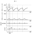
Qb=v2×A (区間a、b) (1)
Qb=(v1+v2)×A (区間c、d) (2)
v1は、第1プランジャ21の移動速度である。v2は、第2プランジャ22の移動速度である。Aは、第1プランジャ21と第2プランジャ22の断面積であり、既知の値である。ただし、第1プランジャ21と第2プランジャ22の断面積が同一であると仮定している。
図3は、2つの送液ポンプ1001、1002を備える液体クロマトグラフ200の構成を示す模式図である。図3に示す液体クロマトグラフ200は、送液ポンプ1001、送液ポンプ1002、インジェクタ2、分離カラム3、検出器4、廃液容器5、及びシステム制御部7を備える。送液ポンプ1001と送液ポンプ1002は、本実施例による送液ポンプ1(図1)と同じ構成を備える。
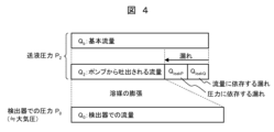
図4は、送液ポンプ1の流量精度に影響を与える因子の関係を模式的に説明する図である。図4では、紙面の左右方向に長い長方形で流量を示している。各長方形の左右方向の長さが、流量(体積流量)の大きさを示す。なお、溶媒の送液圧力(吐出圧力)をP2で表し、検出器4での溶媒の圧力をP0で表す。送液圧力P2は、送液ポンプ1の内部での溶媒の圧力であり、圧力センサ110で測定される圧力である。検出器4での溶媒の圧力P0は、大気圧にほぼ等しく、送液圧力P2よりも低い。
図5に一点鎖線3で示した流量特性を、式(3)で近似して表す。
Q0=exp(f(P2))×(Qb-Cleakp×P2-Cleakq×Qb)
+Qoffset (3)
式(3)において、Q0は検出器4での流量、P2は送液圧力、f(P2)は送液圧力P2に対する膨張率の関数(送液圧力P2での溶媒の体積に対する大気圧での溶媒の体積の比率)、Qbは基本流量、Cleakpは圧力に依存する漏れに関する比例係数、Cleakqは流量に依存する漏れに関する比例係数、Qoffsetは近似式の調整係数である。
Qb=C1×Q0+C0 (4)
とする。ただし、パラメータC1、C0は、
C1=1/((1-Cleakq)×exp(f(P2))) (5)
C0=(1/(1-Cleakq))
×(Cleakp×P2-Qoffset/exp(f(P2)) (6)
である。また、C1、C0が送液圧力P2に対して線形に変化するパラメータ(送液圧力P2の1次関数で表されるパラメータ)であるとすると、
C1=C1a×P2+C1b (7)
C0=C0a×P2+C0b (8)
と表される。
式(5)と式(6)(又は式(7)と式(8))に示すように、補正パラメータC1、C0は、送液圧力P2に依存する。送液圧力P2は、分離カラム3や配管の状態と、温度による溶媒の粘度の変化などによって変化する。このため、送液圧力P2に応じてパラメータC1、C0を調整し、調整したパラメータC1、C0に基づいて送液ポンプ1を駆動させることが望ましい。そこで、圧力センサ110の測定値をコントローラ10にフィードバックさせて、コントローラ10がパラメータC1、C0を再計算(調整)することが望ましい。
式(5)と式(6)で表される補正パラメータC1、C0は、溶媒ごとに、複数の基本流量Qbについて、送液圧力P2に対する検出器4での溶媒の流量Q0を測定することで決定することができる。検出器4での溶媒の流量Q0は、流量計8で測定することができる。なお、測定する基本流量Qbの数が多いほど、補正パラメータC1、C0をより精度良く求めることができる。
Claims (4)
- 液体を吐出する送液ポンプであって、
移動可能な第1プランジャを備える第1プランジャポンプと、
移動可能な第2プランジャを備え、前記第1プランジャポンプと接続された第2プランジャポンプと、
前記第2プランジャポンプの下流側に配置され、前記第2プランジャポンプから吐出された前記液体の圧力である送液圧力を測定する圧力センサと、
前記圧力センサが測定した前記送液圧力を入力するとともに、前記第1プランジャの駆動と前記第2プランジャの駆動を制御する制御部と、
を備え、
前記制御部は、前記送液圧力に依存するパラメータと、前記送液圧力と、前記液体の予め設定された流量である目標流量とを用いて、前記第1プランジャの移動速度と前記第2プランジャの移動速度を求め、
前記パラメータは、前記送液圧力と前記液体の流量との関係を表す式のパラメータであるとともに、基本流量を前記液体の流量から求める式のパラメータであり、
前記基本流量は、漏れがない場合に前記送液ポンプから吐出される、圧縮された状態の前記液体の流量である、
ことを特徴とする送液ポンプ。 - 前記制御部は、前記送液ポンプが前記液体を吐出している間に、前記圧力センサから前記送液圧力を入力して前記パラメータを計算して求め、求めた前記パラメータを用いて前記第1プランジャの移動速度と前記第2プランジャの移動速度を求める、
請求項1に記載の送液ポンプ。 - 前記パラメータは、前記送液圧力に対して線形に変化するパラメータである、
請求項1に記載の送液ポンプ。 - 前記液体の流量を測定する流量計を備え、
前記制御部は、前記送液圧力と前記流量計が測定した流量との関係に基づいて、前記パラメータを求める、
請求項1に記載の送液ポンプ。
Priority Applications (5)
| Application Number | Priority Date | Filing Date | Title |
|---|---|---|---|
| JP2021214281A JP7675644B2 (ja) | 2021-12-28 | 2021-12-28 | 送液ポンプ |
| US18/715,904 US12546299B2 (en) | 2021-12-28 | 2022-11-14 | Liquid delivery pump |
| PCT/JP2022/042160 WO2023127327A1 (ja) | 2021-12-28 | 2022-11-14 | 送液ポンプ |
| EP22912797.2A EP4459276A4 (en) | 2021-12-28 | 2022-11-14 | LIQUID DISPENSING PUMP |
| CN202280080410.4A CN118355275A (zh) | 2021-12-28 | 2022-11-14 | 送液泵 |
Applications Claiming Priority (1)
| Application Number | Priority Date | Filing Date | Title |
|---|---|---|---|
| JP2021214281A JP7675644B2 (ja) | 2021-12-28 | 2021-12-28 | 送液ポンプ |
Publications (3)
| Publication Number | Publication Date |
|---|---|
| JP2023097906A JP2023097906A (ja) | 2023-07-10 |
| JP2023097906A5 JP2023097906A5 (ja) | 2024-07-31 |
| JP7675644B2 true JP7675644B2 (ja) | 2025-05-13 |
Family
ID=86998789
Family Applications (1)
| Application Number | Title | Priority Date | Filing Date |
|---|---|---|---|
| JP2021214281A Active JP7675644B2 (ja) | 2021-12-28 | 2021-12-28 | 送液ポンプ |
Country Status (5)
| Country | Link |
|---|---|
| US (1) | US12546299B2 (ja) |
| EP (1) | EP4459276A4 (ja) |
| JP (1) | JP7675644B2 (ja) |
| CN (1) | CN118355275A (ja) |
| WO (1) | WO2023127327A1 (ja) |
Citations (5)
| Publication number | Priority date | Publication date | Assignee | Title |
|---|---|---|---|---|
| EP2244091B1 (en) | 2009-04-21 | 2015-09-30 | Agilent Technologies, Inc. | Leak detection upstream of a mixing point |
| WO2019082243A1 (ja) | 2017-10-23 | 2019-05-02 | 株式会社島津製作所 | 送液装置及び流体クロマトグラフ |
| WO2019220563A1 (ja) | 2018-05-16 | 2019-11-21 | 株式会社島津製作所 | 送液装置及び液体クロマトグラフ |
| WO2021005728A1 (ja) | 2019-07-09 | 2021-01-14 | 株式会社島津製作所 | 送液ポンプ及び液体クロマトグラフ |
| WO2021192929A1 (ja) | 2020-03-24 | 2021-09-30 | 株式会社日立ハイテク | 送液装置および送液方法 |
Family Cites Families (1)
| Publication number | Priority date | Publication date | Assignee | Title |
|---|---|---|---|---|
| JP2009013957A (ja) * | 2007-07-09 | 2009-01-22 | Hitachi High-Technologies Corp | 送液装置とその制御方法 |
-
2021
- 2021-12-28 JP JP2021214281A patent/JP7675644B2/ja active Active
-
2022
- 2022-11-14 CN CN202280080410.4A patent/CN118355275A/zh active Pending
- 2022-11-14 US US18/715,904 patent/US12546299B2/en active Active
- 2022-11-14 EP EP22912797.2A patent/EP4459276A4/en active Pending
- 2022-11-14 WO PCT/JP2022/042160 patent/WO2023127327A1/ja not_active Ceased
Patent Citations (5)
| Publication number | Priority date | Publication date | Assignee | Title |
|---|---|---|---|---|
| EP2244091B1 (en) | 2009-04-21 | 2015-09-30 | Agilent Technologies, Inc. | Leak detection upstream of a mixing point |
| WO2019082243A1 (ja) | 2017-10-23 | 2019-05-02 | 株式会社島津製作所 | 送液装置及び流体クロマトグラフ |
| WO2019220563A1 (ja) | 2018-05-16 | 2019-11-21 | 株式会社島津製作所 | 送液装置及び液体クロマトグラフ |
| WO2021005728A1 (ja) | 2019-07-09 | 2021-01-14 | 株式会社島津製作所 | 送液ポンプ及び液体クロマトグラフ |
| WO2021192929A1 (ja) | 2020-03-24 | 2021-09-30 | 株式会社日立ハイテク | 送液装置および送液方法 |
Also Published As
| Publication number | Publication date |
|---|---|
| EP4459276A1 (en) | 2024-11-06 |
| CN118355275A (zh) | 2024-07-16 |
| EP4459276A4 (en) | 2025-06-18 |
| WO2023127327A1 (ja) | 2023-07-06 |
| US12546299B2 (en) | 2026-02-10 |
| US20250035096A1 (en) | 2025-01-30 |
| JP2023097906A (ja) | 2023-07-10 |
Similar Documents
| Publication | Publication Date | Title |
|---|---|---|
| US7278329B2 (en) | Chromatography system with blockage determination | |
| US6923916B1 (en) | Liquid chromatograph pump and control method therefor | |
| US10105666B2 (en) | Method for dispensing a fluid medium | |
| JP4377761B2 (ja) | 液体クロマトグラフ装置 | |
| US20080022765A1 (en) | Flow meter with a metering device and a control unit | |
| US20040151594A1 (en) | High pressure reciprocating pump and control of the same | |
| US20080047611A1 (en) | Fluid pump having low pressure metering and high pressure delivering | |
| CN110088472B (zh) | 医用液体的容积泵和血液治疗设备及其控制的方法 | |
| JP5155937B2 (ja) | 送液装置および液体クロマトグラフ装置 | |
| JP2013217816A (ja) | 液体クロマトグラフ | |
| JP7675644B2 (ja) | 送液ポンプ | |
| JP4377900B2 (ja) | 液体クロマトグラフ装置 | |
| JPH11343978A (ja) | 液体供給装置 | |
| JP7595029B2 (ja) | ガス供給システム、機械発泡システム及びガスを供給する方法 | |
| WO2020179160A1 (ja) | 送液ポンプ、液体クロマトグラフ装置 | |
| EP1724576A2 (en) | Chromatography system with fluid intake management | |
| GB2454783A (en) | HPLC constant flow pump to enable low-flow operation, wherein thermal-based sensors are contained within an isothermal block | |
| JP7503482B2 (ja) | 送液ポンプ及び送液方法 | |
| JP7756594B2 (ja) | 送液ポンプ及び送液方法 | |
| WO2006087037A1 (en) | Fluid pump having high pressure metering and high pressure delivering |
Legal Events
| Date | Code | Title | Description |
|---|---|---|---|
| A521 | Request for written amendment filed |
Free format text: JAPANESE INTERMEDIATE CODE: A523 Effective date: 20240723 |
|
| A621 | Written request for application examination |
Free format text: JAPANESE INTERMEDIATE CODE: A621 Effective date: 20240723 |
|
| TRDD | Decision of grant or rejection written | ||
| A01 | Written decision to grant a patent or to grant a registration (utility model) |
Free format text: JAPANESE INTERMEDIATE CODE: A01 Effective date: 20250401 |
|
| A61 | First payment of annual fees (during grant procedure) |
Free format text: JAPANESE INTERMEDIATE CODE: A61 Effective date: 20250428 |
|
| R150 | Certificate of patent or registration of utility model |
Ref document number: 7675644 Country of ref document: JP Free format text: JAPANESE INTERMEDIATE CODE: R150 |