JP7675706B2 - 空冷式蒸気凝縮器 - Google Patents
空冷式蒸気凝縮器 Download PDFInfo
- Publication number
- JP7675706B2 JP7675706B2 JP2022516242A JP2022516242A JP7675706B2 JP 7675706 B2 JP7675706 B2 JP 7675706B2 JP 2022516242 A JP2022516242 A JP 2022516242A JP 2022516242 A JP2022516242 A JP 2022516242A JP 7675706 B2 JP7675706 B2 JP 7675706B2
- Authority
- JP
- Japan
- Prior art keywords
- heat exchanger
- condenser
- air
- section
- tubes
- Prior art date
- Legal status (The legal status is an assumption and is not a legal conclusion. Google has not performed a legal analysis and makes no representation as to the accuracy of the status listed.)
- Active
Links
Images


Classifications
-
- F—MECHANICAL ENGINEERING; LIGHTING; HEATING; WEAPONS; BLASTING
- F28—HEAT EXCHANGE IN GENERAL
- F28B—STEAM OR VAPOUR CONDENSERS
- F28B1/00—Condensers in which the steam or vapour is separate from the cooling medium by walls, e.g. surface condenser
- F28B1/06—Condensers in which the steam or vapour is separate from the cooling medium by walls, e.g. surface condenser using air or other gas as the cooling medium
-
- F—MECHANICAL ENGINEERING; LIGHTING; HEATING; WEAPONS; BLASTING
- F28—HEAT EXCHANGE IN GENERAL
- F28B—STEAM OR VAPOUR CONDENSERS
- F28B9/00—Auxiliary systems, arrangements, or devices
- F28B9/02—Auxiliary systems, arrangements, or devices for feeding steam or vapour to condensers
-
- F—MECHANICAL ENGINEERING; LIGHTING; HEATING; WEAPONS; BLASTING
- F28—HEAT EXCHANGE IN GENERAL
- F28D—HEAT-EXCHANGE APPARATUS, NOT PROVIDED FOR IN ANOTHER SUBCLASS, IN WHICH THE HEAT-EXCHANGE MEDIA DO NOT COME INTO DIRECT CONTACT
- F28D1/00—Heat-exchange apparatus having stationary conduit assemblies for one heat-exchange medium only, the media being in contact with different sides of the conduit wall, in which the other heat-exchange medium is a large body of fluid, e.g. domestic or motor car radiators
- F28D1/02—Heat-exchange apparatus having stationary conduit assemblies for one heat-exchange medium only, the media being in contact with different sides of the conduit wall, in which the other heat-exchange medium is a large body of fluid, e.g. domestic or motor car radiators with heat-exchange conduits immersed in the body of fluid
- F28D1/0233—Heat-exchange apparatus having stationary conduit assemblies for one heat-exchange medium only, the media being in contact with different sides of the conduit wall, in which the other heat-exchange medium is a large body of fluid, e.g. domestic or motor car radiators with heat-exchange conduits immersed in the body of fluid with air flow channels
- F28D1/024—Heat-exchange apparatus having stationary conduit assemblies for one heat-exchange medium only, the media being in contact with different sides of the conduit wall, in which the other heat-exchange medium is a large body of fluid, e.g. domestic or motor car radiators with heat-exchange conduits immersed in the body of fluid with air flow channels with an air driving element
-
- F—MECHANICAL ENGINEERING; LIGHTING; HEATING; WEAPONS; BLASTING
- F28—HEAT EXCHANGE IN GENERAL
- F28D—HEAT-EXCHANGE APPARATUS, NOT PROVIDED FOR IN ANOTHER SUBCLASS, IN WHICH THE HEAT-EXCHANGE MEDIA DO NOT COME INTO DIRECT CONTACT
- F28D1/00—Heat-exchange apparatus having stationary conduit assemblies for one heat-exchange medium only, the media being in contact with different sides of the conduit wall, in which the other heat-exchange medium is a large body of fluid, e.g. domestic or motor car radiators
- F28D1/02—Heat-exchange apparatus having stationary conduit assemblies for one heat-exchange medium only, the media being in contact with different sides of the conduit wall, in which the other heat-exchange medium is a large body of fluid, e.g. domestic or motor car radiators with heat-exchange conduits immersed in the body of fluid
- F28D1/04—Heat-exchange apparatus having stationary conduit assemblies for one heat-exchange medium only, the media being in contact with different sides of the conduit wall, in which the other heat-exchange medium is a large body of fluid, e.g. domestic or motor car radiators with heat-exchange conduits immersed in the body of fluid with tubular conduits
- F28D1/0408—Multi-circuit heat exchangers, e.g. integrating different heat exchange sections in the same unit or heat exchangers for more than two fluids
- F28D1/0426—Multi-circuit heat exchangers, e.g. integrating different heat exchange sections in the same unit or heat exchangers for more than two fluids with units having particular arrangement relative to the large body of fluid, e.g. with interleaved units or with adjacent heat exchange units in common air flow or with units extending at an angle to each other or with units arranged around a central element
- F28D1/0443—Combination of units extending one beside or one above the other
-
- F—MECHANICAL ENGINEERING; LIGHTING; HEATING; WEAPONS; BLASTING
- F28—HEAT EXCHANGE IN GENERAL
- F28D—HEAT-EXCHANGE APPARATUS, NOT PROVIDED FOR IN ANOTHER SUBCLASS, IN WHICH THE HEAT-EXCHANGE MEDIA DO NOT COME INTO DIRECT CONTACT
- F28D1/00—Heat-exchange apparatus having stationary conduit assemblies for one heat-exchange medium only, the media being in contact with different sides of the conduit wall, in which the other heat-exchange medium is a large body of fluid, e.g. domestic or motor car radiators
- F28D1/02—Heat-exchange apparatus having stationary conduit assemblies for one heat-exchange medium only, the media being in contact with different sides of the conduit wall, in which the other heat-exchange medium is a large body of fluid, e.g. domestic or motor car radiators with heat-exchange conduits immersed in the body of fluid
- F28D1/04—Heat-exchange apparatus having stationary conduit assemblies for one heat-exchange medium only, the media being in contact with different sides of the conduit wall, in which the other heat-exchange medium is a large body of fluid, e.g. domestic or motor car radiators with heat-exchange conduits immersed in the body of fluid with tubular conduits
- F28D1/053—Heat-exchange apparatus having stationary conduit assemblies for one heat-exchange medium only, the media being in contact with different sides of the conduit wall, in which the other heat-exchange medium is a large body of fluid, e.g. domestic or motor car radiators with heat-exchange conduits immersed in the body of fluid with tubular conduits the conduits being straight
- F28D1/0535—Heat-exchange apparatus having stationary conduit assemblies for one heat-exchange medium only, the media being in contact with different sides of the conduit wall, in which the other heat-exchange medium is a large body of fluid, e.g. domestic or motor car radiators with heat-exchange conduits immersed in the body of fluid with tubular conduits the conduits being straight the conduits having a non-circular cross-section
- F28D1/05366—Assemblies of conduits connected to common headers, e.g. core type radiators
- F28D1/05383—Assemblies of conduits connected to common headers, e.g. core type radiators with multiple rows of conduits or with multi-channel conduits
Landscapes
- Engineering & Computer Science (AREA)
- Mechanical Engineering (AREA)
- General Engineering & Computer Science (AREA)
- Physics & Mathematics (AREA)
- Thermal Sciences (AREA)
- Heat-Exchange Devices With Radiators And Conduit Assemblies (AREA)
- Details Of Heat-Exchange And Heat-Transfer (AREA)
Description
2 熱交換器パネル 12 上部ボンネット
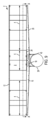
4 一次凝縮器セクション 14 下部管シート
6 二次凝縮器セクション 15 持ち上げ/支持アングル
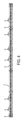
7 管 16 下部ボンネット
8 凝縮器バンドル 18 ステム入口/凝縮液出口
10 上部管シート 20 遮蔽板
21 穿孔 50 ハンガー
22 波形エッジ 54 ハンガーロッド
24 二次下部ボンネット 56 ハンガースリーブ
26 ノズル(二次下部ボンネット用) 58 ハンガー固定ディスク又はノブ
27 ACC凝縮器モジュール(セル) 60 ハンガー凹部
28 上部蒸気マニホールド 62 下部構造モジュール
29 Y字状ノズル 64 プレナムセクションモジュール
30 竪管(LSMからUSM) 66 組立型蒸気分配マニホールド
31 タービン排気ダクト 68 組立型タービン排気ダクト
32 下部蒸気分配マニホールド 70 空気偏向シール
34 ACCセルのストリート/セル列 72 ファンデッキプレート
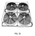
36 (熱交換器セクションの)フレーム 74 小型ファン
37 熱交換モジュール 76 地上タービン排気ダクト
40 偏向遮蔽板 78 端部竪管(GLTEDからESDM)
42 凝縮液配管
Claims (36)
- 空冷式蒸気凝縮器であって、
熱交換器セクションに支持された複数の熱交換器パネルを通じて空気を引き込む単一のファン又は複数のファンを有するプレナムセクションを備え、
各熱交換器パネルは、長手方向軸と、当該長手方向軸に対して直交する交差軸とを有し、
各熱交換器パネルは、複数の管と、各管の上端部に接続されて流体連通する上部ボンネットと、前記複数の管のうちの第1サブセットの下端部のみに接続されて流体連通する下部ボンネットとを備え、
前記下部ボンネットの内部にある内部二次チャンバは、前記複数の管のうちの第2サブセットの下端部のみに接続されて流体連通し、
各下部ボンネットは、単一の蒸気入口を有し、
前記空冷式蒸気凝縮器は、更に、複数の熱交換器パネルの中間部において、前記熱交換器セクションの下方に配置されるとともに、前記複数の熱交換器パネルの長手方向軸に対して垂直である軸に沿って配置された、蒸気分配マニホールドを備え、
前記蒸気分配マニホールドは、その上面に複数の接続部を備え、
前記複数の接続部のそれぞれは、対応する前記単一の蒸気入口に接続されるように構成されている、
空冷式蒸気凝縮器。 - 各熱交換器パネルは、
二次凝縮器セクションと、
一次凝縮器セクションと、
前記二次凝縮器セクション及び前記一次凝縮器セクションの各管の上端部に接続されて流体連通する前記上部ボンネットと、
前記一次凝縮器セクションの各管である前記第1サブセットの下端部に接続されて流体連通する前記下部ボンネットと、
前記二次凝縮器セクションの各管である前記第2サブセットの下端部に接続されて流体連通する、前記下部ボンネットの内部にある前記内部二次チャンバと、を備える、請求項1に記載の空冷式蒸気凝縮器。 - 各熱交換器パネルは、前記二次凝縮器セクションに隣接する2つの一次凝縮器セクションを備える、請求項2に記載の空冷式蒸気凝縮器。
- 前記二次凝縮器セクションは、前記熱交換器パネルに沿って中心部に配置され、両端部が一次凝縮器セクションに隣接する、請求項3に記載の空冷式蒸気凝縮器。
- 前記蒸気分配マニホールドのシリンダは、第1の端部がタービン排気ダクトに取り付けられている、請求項1に記載の空冷式蒸気凝縮器。
- 各熱交換器パネルは、複数の可撓性を有する吊り下げ支持体によって前記熱交換器セクションのフレームから独立して吊り下げられている、請求項1に記載の空冷式蒸気凝縮器。
- 単一の熱交換器セクションにおける全ての熱交換器パネルは、同じ方向に配向されている、請求項1~6のいずれか1つに記載の空冷式蒸気凝縮器。
- 単一の熱交換器セクションにおける全ての熱交換器パネルは、垂直方向に配向されている、請求項1~6のいずれか1つに記載の空冷式蒸気凝縮器。
- 単一の熱交換器セクションにおける全ての熱交換器パネルは、垂直に対して同じ角度で、同じ方向に配向されている、請求項1~6のいずれか1つに記載の空冷式蒸気凝縮器。
- 単一の熱交換器セクションの一方の側の全ての熱交換器パネルは、垂直に対して一方向に傾斜し、単一の熱交換器セクションの他方の側の全ての熱交換器パネルは、垂直に対して反対方向に傾斜している、請求項1~6のいずれか1つに記載の空冷式蒸気凝縮器。
- 前記プレナムセクションは、ファンデッキの骨格に載置され、前記熱交換器セクションで全ての熱交換器パネルにわたって空気を吸い込む単一のファンを備える、請求項1~6のいずれか1つに記載の空冷式蒸気凝縮器。
- 前記プレナムセクションは、ファンデッキの骨格に載置された複数のファンデッキプレートを備え、各ファンデッキプレートは、複数のファンを備える、請求項1~6のいずれか1つに記載の空冷式蒸気凝縮器。
- 各ファンは、2以下の熱交換器パネルにわたって空気を吸引する、請求項12に記載の空冷式蒸気凝縮器。
- 各可撓性を有する吊り下げ支持体は、接続スリーブに両端部を接続された中央ロッドを備え、各可撓性を有する吊り下げ支持体の第1の接続スリーブは、前記熱交換器セクションのフレームに接続され、各可撓性を有する吊り下げ支持体の第2の接続スリーブは、前記熱交換器パネルの管シートに接続されている、請求項6に記載の空冷式蒸気凝縮器。
- 前記熱交換器パネルにおける前記複数の管は、2.0m~2.8mの長さ、120mmの断面高さ、及び4~10mmの断面幅を有する、請求項1に記載の空冷式蒸気凝縮器。
- 前記複数の管は、5.2~7mmの断面幅を有する、請求項15に記載の空冷式蒸気凝縮器。
- 前記複数の管は、6.0mmの断面幅を有する、請求項16に記載の空冷式蒸気凝縮器。
- 前記熱交換器パネルにおける前記複数の管は、当該管の平坦な側面に取り付けられたフィンを有し、前記フィンは、9~10mmの高さを有し、1インチあたり5~12個のフィンの間隔で配置されている、請求項1に記載の空冷式蒸気凝縮器。
- 前記熱交換器パネルにおける前記複数の管は、当該管の平坦な側面に取り付けられたフィンを有し、前記フィンは、隣接する管間の空間にわたって18mm~20mmの高さを有して隣接する管に接触し、前記フィンは、1インチあたり5~12個のフィンの間隔で配置されている、請求項2に記載の空冷式蒸気凝縮器。
- 請求項1に記載の空冷式蒸気凝縮器の組立方法であって、
熱交換器セクションのフレーム及び前記熱交換器パネルを備える熱交換器セクションを地上で組み立てるステップと、
前記熱交換器パネルの直下で隣接する蒸気分配マニホールドを吊り下げ可能な地上からの高さで前記熱交換器セクションを支持するステップと、
ファンデッキ及びファンアセンブリを備えるプレナムセクションを地上で組み立てるステップと、
組み立てられた前記熱交換器セクション及び前記蒸気分配マニホールドを持ち上げて、対応する下部構造体の上に配置するステップと、
組み立てられた前記プレナムセクションを持ち上げて前記熱交換器セクションの上に配置するステップと、
を含む、組立方法。 - 空冷式蒸気凝縮器であって、
熱交換器セクションに支持された複数の熱交換器パネルを通じて空気を引き込む単一のファン又は複数のファンを有するプレナムセクションを備え、
各熱交換器パネルは、長手方向軸と、当該長手方向軸に対して直交する交差軸とを有し、
各熱交換器パネルは、複数の凝縮器管と、各凝縮器管の上端部に接続されて流体連通する上部ボンネットと、各凝縮器管の下端部に接続されて流体連通する下部ボンネットとを備え、
各下部ボンネットは、単一の蒸気入口を有し、
前記空冷式蒸気凝縮器は、更に、前記熱交換器パネルの中間部において、前記熱交換器セクションの下方に配置され、前記熱交換器セクションの下部側に直接的に隣接し、前記複数の熱交換器パネルの長手方向軸に対して垂直である軸に沿って配置された、蒸気分配マニホールドを備え、
前記蒸気分配マニホールドは、その上面に、前記下部ボンネットの入口に接続されるように構成された複数の接続部を備え、
各熱交換パネルは、複数の可撓性を有する吊り下げ支持体によって凝縮器モジュールのフレームから吊り下げられている、
空冷式蒸気凝縮器。 - 各熱交換器パネルは、前記熱交換器パネル内の全ての管が当該管の下端部から蒸気を受ける第1段の凝縮器を備える、請求項21に記載の空冷式蒸気凝縮器。
- 前記上部ボンネットは、前記凝縮器管から非凝縮性ガスを受け取るように構成されている、請求項21に記載の空冷式蒸気凝縮器。
- 各可撓性を有する吊り下げ支持体は、接続スリーブに両端部を接続された中央ロッドを備え、各可撓性を有する吊り下げ支持体の第1の接続スリーブは、前記凝縮器モジュールのフレームに接続され、各可撓性を有する吊り下げ支持体の第2の接続スリーブは、前記熱交換器パネルの管シートに接続されている、請求項21に記載の空冷式蒸気凝縮器。
- 前記複数の凝縮器管は、2.0m~2.8mの長さ、120mmの断面高さ、及び4~10mmの断面幅を有する、請求項21に記載の空冷式蒸気凝縮器。
- 前記凝縮器管は、5.2~7mmの断面幅を有する、請求項25に記載の空冷式蒸気凝縮器。
- 前記凝縮器管は、6.0mmの断面幅を有する、請求項26に記載の空冷式蒸気凝縮器。
- 前記複数の凝縮器管は、当該凝縮器管の平坦な側面に取り付けられたフィンを有し、前記フィンは、9~10mmの高さを有し、1インチあたり5~12個のフィンで間隔を空けて配置されている、請求項22に記載の空冷式蒸気凝縮器。
- 前記複数の凝縮器管は、当該凝縮器管の平坦な側面に取り付けられたフィンを有し、前記フィンは、隣接する管間の空間にわたって18mm~20mmの高さを有して隣接する管に接触し、前記フィンは、1インチあたり5~12個のフィンの間隔で配置されている、請求項21に記載の空冷式蒸気凝縮器。
- 請求項21に記載の空冷式蒸気凝縮器の組立方法であって、
熱交換器セクションフレーム及び前記熱交換器パネルを備える熱交換器セクションを地上で組み立てるステップと、
前記熱交換器パネルの直下で隣接する蒸気分配マニホールドを吊り下げるのに十分な地上からの高さで前記熱交換器セクションを支持するステップと、
ファンデッキ及びファンアセンブリを備えるプレナムセクションを地上で組み立てるステップと、
組み立てられた前記熱交換器セクション及び前記蒸気分配マニホールドを持ち上げて、対応する下部構造体の上に配置するステップと、
組み立てられた前記プレナムセクションを持ち上げて前記熱交換器セクションの上に配置するステップと、
を含む、組立方法。 - 単一の熱交換器セクションにおける全ての熱交換器パネルは、同じ方向に配向されている、請求項21~29のいずれか1つに記載の空冷式蒸気凝縮器。
- 単一の熱交換器セクションにおける全ての熱交換器パネルは、垂直方向に配向されている、請求項21~29のいずれか1つに記載の空冷式蒸気凝縮器。
- 単一の熱交換器セクションにおける全ての熱交換器パネルは、垂直に対して同じ角度で、同じ方向に配向されている、請求項21~29のいずれか1つに記載の空冷式蒸気凝縮器。
- 単一の熱交換器セクションの一方の側の全ての熱交換器パネルは、垂直に対して一方向に傾斜し、単一の熱交換器セクションの他方の側の全ての熱交換器パネルは、垂直に対して反対方向に傾斜している、請求項21~29のいずれか1つに記載の空冷式蒸気凝縮器。
- 前記プレナムセクションは、ファンデッキの骨格に載置された複数のファンデッキプレートを備え、各ファンデッキプレートは、複数のファンを備え、各ファンは、2以下の熱交換器パネルにわたって空気を吸い込む、請求項21~29のいずれか1つに記載の空冷式蒸気凝縮器。
- 前記上部ボンネットは、前記管から非凝縮性ガスを受け取るように構成されている、請求項1に記載の空冷式蒸気凝縮器。
Applications Claiming Priority (13)
| Application Number | Priority Date | Filing Date | Title |
|---|---|---|---|
| US201962900195P | 2019-09-13 | 2019-09-13 | |
| US62/900,195 | 2019-09-13 | ||
| US201962902521P | 2019-09-19 | 2019-09-19 | |
| US62/902,521 | 2019-09-19 | ||
| US201962928116P | 2019-10-30 | 2019-10-30 | |
| US62/928,116 | 2019-10-30 | ||
| US201962946039P | 2019-12-10 | 2019-12-10 | |
| US62/946,039 | 2019-12-10 | ||
| US202016796200A | 2020-02-20 | 2020-02-20 | |
| US16/796,200 | 2020-02-20 | ||
| US16/815,862 US10982904B2 (en) | 2018-09-07 | 2020-03-11 | Advanced large scale field-erected air cooled industrial steam condenser |
| US16/815,862 | 2020-03-11 | ||
| PCT/US2020/022259 WO2021050105A1 (en) | 2019-09-13 | 2020-03-12 | Advanced large scale field-erected air cooled industrial steam condenser |
Publications (2)
| Publication Number | Publication Date |
|---|---|
| JP2022547603A JP2022547603A (ja) | 2022-11-14 |
| JP7675706B2 true JP7675706B2 (ja) | 2025-05-13 |
Family
ID=74867144
Family Applications (1)
| Application Number | Title | Priority Date | Filing Date |
|---|---|---|---|
| JP2022516242A Active JP7675706B2 (ja) | 2019-09-13 | 2020-03-12 | 空冷式蒸気凝縮器 |
Country Status (11)
| Country | Link |
|---|---|
| EP (2) | EP4028706B1 (ja) |
| JP (1) | JP7675706B2 (ja) |
| KR (1) | KR20220056870A (ja) |
| CN (1) | CN114761749B (ja) |
| AU (1) | AU2020347054A1 (ja) |
| CA (1) | CA3154277A1 (ja) |
| ES (1) | ES3047766T3 (ja) |
| MX (1) | MX2022003073A (ja) |
| PL (1) | PL4028706T3 (ja) |
| WO (1) | WO2021050105A1 (ja) |
| ZA (1) | ZA202204165B (ja) |
Families Citing this family (2)
| Publication number | Priority date | Publication date | Assignee | Title |
|---|---|---|---|---|
| MX2024001942A (es) * | 2021-08-13 | 2024-04-03 | Evapco Inc | Condensador de vapor enfriado por aire con condensador de segunda etapa mejorado. |
| BE1031154B1 (fr) | 2022-12-06 | 2024-07-15 | Mehmet Zahit Inan | Aerocondenseur a tirage induit |
Citations (7)
| Publication number | Priority date | Publication date | Assignee | Title |
|---|---|---|---|---|
| US20050161094A1 (en) | 2003-07-08 | 2005-07-28 | Gea Energietechnik Gmbh | Exhaust-steam pipeline for a steam power plant |
| US20100006270A1 (en) | 2008-07-10 | 2010-01-14 | Spx Cooling Technologies, Inc. (De Corp.) | Modular air-cooled condenser apparatus and method |
| US20130312932A1 (en) | 2012-05-23 | 2013-11-28 | Spx Cooling Technologies, Inc. | Modular air cooled condenser apparatus and method |
| US20150345166A1 (en) | 2013-05-28 | 2015-12-03 | Spx Cooling Technologies, Inc. | Modular Air Cooled Condenser Apparatus and Method |
| US20170363357A1 (en) | 2016-06-21 | 2017-12-21 | Evapco, Inc. | Mini-tube air cooled industrial steam condenser |
| US20170363358A1 (en) | 2016-06-21 | 2017-12-21 | Evapco, Inc. | All-secondary air cooled industrial steam condenser |
| US20190242660A1 (en) | 2016-08-24 | 2019-08-08 | Spx Dry Cooling Belgium | Induced draft air-cooled condenser |
Family Cites Families (7)
| Publication number | Priority date | Publication date | Assignee | Title |
|---|---|---|---|---|
| DE1945314C3 (de) * | 1969-09-06 | 1974-03-07 | Kraftwerk Union Ag, 4330 Muelheim | Abdampfleitung für Dampfkraftanlagen |
| GB1370321A (en) * | 1971-02-11 | 1974-10-16 | Gkn Birwelco Ltd | Steam condensers |
| US3707185A (en) * | 1971-03-25 | 1972-12-26 | Modine Mfg Co | Modular air cooled condenser |
| MX2014012442A (es) * | 2012-04-16 | 2015-04-14 | Evapco Inc | Aparato y metodo para conectar serpentines intercambiadores de calor enfriados por aire al colector de distribucion de vapor. |
| WO2017202730A1 (en) * | 2016-05-25 | 2017-11-30 | Spx Dry Cooling Belgium | Air-cooled condenser apparatus and method |
| BE1024229B1 (fr) * | 2017-10-31 | 2019-05-27 | Hamon Thermal Europe S.A. | Unité de refroidissement, installation et procédé |
| CN109059572A (zh) * | 2018-08-21 | 2018-12-21 | 吕刚 | 一种环境工程用的冷凝器设备 |
-
2020
- 2020-03-12 JP JP2022516242A patent/JP7675706B2/ja active Active
- 2020-03-12 MX MX2022003073A patent/MX2022003073A/es unknown
- 2020-03-12 KR KR1020227011551A patent/KR20220056870A/ko active Pending
- 2020-03-12 AU AU2020347054A patent/AU2020347054A1/en active Pending
- 2020-03-12 WO PCT/US2020/022259 patent/WO2021050105A1/en not_active Ceased
- 2020-03-12 EP EP20863838.7A patent/EP4028706B1/en active Active
- 2020-03-12 CA CA3154277A patent/CA3154277A1/en active Pending
- 2020-03-12 EP EP25189754.2A patent/EP4647702A3/en active Pending
- 2020-03-12 CN CN202080074669.9A patent/CN114761749B/zh active Active
- 2020-03-12 ES ES20863838T patent/ES3047766T3/es active Active
- 2020-03-12 PL PL20863838.7T patent/PL4028706T3/pl unknown
-
2022
- 2022-04-12 ZA ZA2022/04165A patent/ZA202204165B/en unknown
Patent Citations (7)
| Publication number | Priority date | Publication date | Assignee | Title |
|---|---|---|---|---|
| US20050161094A1 (en) | 2003-07-08 | 2005-07-28 | Gea Energietechnik Gmbh | Exhaust-steam pipeline for a steam power plant |
| US20100006270A1 (en) | 2008-07-10 | 2010-01-14 | Spx Cooling Technologies, Inc. (De Corp.) | Modular air-cooled condenser apparatus and method |
| US20130312932A1 (en) | 2012-05-23 | 2013-11-28 | Spx Cooling Technologies, Inc. | Modular air cooled condenser apparatus and method |
| US20150345166A1 (en) | 2013-05-28 | 2015-12-03 | Spx Cooling Technologies, Inc. | Modular Air Cooled Condenser Apparatus and Method |
| US20170363357A1 (en) | 2016-06-21 | 2017-12-21 | Evapco, Inc. | Mini-tube air cooled industrial steam condenser |
| US20170363358A1 (en) | 2016-06-21 | 2017-12-21 | Evapco, Inc. | All-secondary air cooled industrial steam condenser |
| US20190242660A1 (en) | 2016-08-24 | 2019-08-08 | Spx Dry Cooling Belgium | Induced draft air-cooled condenser |
Also Published As
| Publication number | Publication date |
|---|---|
| KR20220056870A (ko) | 2022-05-06 |
| WO2021050105A1 (en) | 2021-03-18 |
| MX2022003073A (es) | 2022-06-02 |
| ZA202204165B (en) | 2022-07-27 |
| CN114761749A (zh) | 2022-07-15 |
| AU2020347054A1 (en) | 2022-04-28 |
| EP4028706B1 (en) | 2025-07-16 |
| EP4028706A1 (en) | 2022-07-20 |
| CA3154277A1 (en) | 2021-03-18 |
| CN114761749B (zh) | 2026-02-27 |
| EP4028706A4 (en) | 2023-09-20 |
| JP2022547603A (ja) | 2022-11-14 |
| PL4028706T3 (pl) | 2025-11-24 |
| EP4647702A2 (en) | 2025-11-12 |
| BR112022004589A2 (pt) | 2022-06-14 |
| ES3047766T3 (en) | 2025-12-04 |
| EP4647702A3 (en) | 2026-01-07 |
Similar Documents
| Publication | Publication Date | Title |
|---|---|---|
| JP7570319B2 (ja) | 先進大規模野外設置型空冷式工業用蒸気凝縮器 | |
| US11933542B2 (en) | Advanced large scale field-erected air cooled industrial steam condenser | |
| JP7675706B2 (ja) | 空冷式蒸気凝縮器 | |
| US12460866B2 (en) | Advanced large scale field-erected air cooled industrial steam condenser | |
| CA3111557C (en) | Advanced large scale field-erected air cooled industrial steam condenser | |
| RU2800622C1 (ru) | Усовершенствованный крупномасштабный монтируемый на месте применения промышленный паровой конденсатор с воздушным охлаждением | |
| RU2799475C2 (ru) | Усовершенствованный крупномасштабный монтируемый на месте промышленный пароконденсатор с водяным охлаждением | |
| BR112022004589B1 (pt) | Condensador de vapor industrial refrigerado a ar e método de montagem de um condensador refrigerado a ar | |
| JP2024509545A (ja) | 空冷式工業蒸気凝縮器用の積層パネル熱交換器 | |
| JP2024529134A (ja) | 改良された第2ステージ凝縮器を備えた空冷式蒸気凝縮器 | |
| BR112021004125B1 (pt) | Condensador de vapor industrial, resfriado com ar, erguido no campo, de grande escala, avançado |
Legal Events
| Date | Code | Title | Description |
|---|---|---|---|
| A621 | Written request for application examination |
Free format text: JAPANESE INTERMEDIATE CODE: A621 Effective date: 20230217 |
|
| A131 | Notification of reasons for refusal |
Free format text: JAPANESE INTERMEDIATE CODE: A131 Effective date: 20240319 |
|
| A601 | Written request for extension of time |
Free format text: JAPANESE INTERMEDIATE CODE: A601 Effective date: 20240618 |
|
| A521 | Request for written amendment filed |
Free format text: JAPANESE INTERMEDIATE CODE: A523 Effective date: 20240627 |
|
| A131 | Notification of reasons for refusal |
Free format text: JAPANESE INTERMEDIATE CODE: A131 Effective date: 20241001 |
|
| A521 | Request for written amendment filed |
Free format text: JAPANESE INTERMEDIATE CODE: A523 Effective date: 20241225 |
|
| TRDD | Decision of grant or rejection written | ||
| A01 | Written decision to grant a patent or to grant a registration (utility model) |
Free format text: JAPANESE INTERMEDIATE CODE: A01 Effective date: 20250401 |
|
| A61 | First payment of annual fees (during grant procedure) |
Free format text: JAPANESE INTERMEDIATE CODE: A61 Effective date: 20250428 |
|
| R150 | Certificate of patent or registration of utility model |
Ref document number: 7675706 Country of ref document: JP Free format text: JAPANESE INTERMEDIATE CODE: R150 |