JP7680921B2 - Vehicle cargo compartment structure and second deck construction set for vehicle - Google Patents
Vehicle cargo compartment structure and second deck construction set for vehicle Download PDFInfo
- Publication number
- JP7680921B2 JP7680921B2 JP2021148713A JP2021148713A JP7680921B2 JP 7680921 B2 JP7680921 B2 JP 7680921B2 JP 2021148713 A JP2021148713 A JP 2021148713A JP 2021148713 A JP2021148713 A JP 2021148713A JP 7680921 B2 JP7680921 B2 JP 7680921B2
- Authority
- JP
- Japan
- Prior art keywords
- vehicle
- deck board
- deck
- luggage compartment
- pair
- Prior art date
- Legal status (The legal status is an assumption and is not a legal conclusion. Google has not performed a legal analysis and makes no representation as to the accuracy of the status listed.)
- Active
Links
Images






Landscapes
- Vehicle Step Arrangements And Article Storage (AREA)
Description
本発明は、車両荷室構造に関し、また、その車両荷室構造を形成するための車両用第2デッキ構築セットに関する。 The present invention relates to a vehicle luggage compartment structure and a second deck construction set for a vehicle for forming the vehicle luggage compartment structure.
下記特許文献1,2には、車両の荷室構造に関する技術が開示されている。下記特許文献1に記載された車両荷室構造は、1枚のボード部材の位置を底面位置と、その上側の位置との間で入れ換え可能とされ、その入れ換えを容易に行える構造となっている。また、下記特許文献2に記載された車両荷室構造は、荷室の前側のシートバックを前側に倒して広い空間を形成し、その空間に重量物や車輪を有する荷物等を運び込み易くした構造となっている。これらをはじめとして、車両の荷室構造は、ユーザーのニーズに応じて種々の態様が求められる。 The following Patent Documents 1 and 2 disclose technologies relating to vehicle luggage compartment structures. The vehicle luggage compartment structure described in Patent Document 1 has a structure in which the position of one board member can be swapped between a bottom position and a position above it, making this swapping easy. In addition, the vehicle luggage compartment structure described in Patent Document 2 has a structure in which the front seat backs of the luggage compartment are tilted forward to form a large space, making it easy to carry heavy objects and luggage with wheels into this space. In addition to these, various aspects of vehicle luggage compartment structures are required according to user needs.
荷室の前側に配されたシートのシートバックを前倒しして背面が略水平にすることが可能な車両において、荷室の容量を確保する目的で、前倒ししたシートバックの背面より低い高さに、荷室のフロア面が形成される場合がある。しかしながら、ユーザーによっては、上記特許文献3に記載された車両のように、フラットなスペースを広く確保することが重要視される場合もある。 In vehicles in which the seat backs of the seats located at the front of the luggage compartment can be folded forward to make the backs approximately horizontal, the floor surface of the luggage compartment may be formed at a height lower than the backs of the folded seat backs in order to ensure the capacity of the luggage compartment. However, some users consider it important to have a large flat space, as in the vehicle described in Patent Document 3 above.
本発明は、そのような実情に鑑みてなされたものであり、広い荷室を確保した車両において、フラットなスペースを形成可能な車両荷室構造を提供することを課題とし、また、そのような車両荷室構造を形成するための車両用第2デッキ構築セットを提供することを課題とする。 The present invention was made in consideration of such circumstances, and aims to provide a vehicle luggage compartment structure capable of forming a flat space in a vehicle with a large luggage compartment, and also aims to provide a second deck construction set for a vehicle for forming such a vehicle luggage compartment structure.
上記課題を解決するために、本発明の車両荷室構造は、
背面が略水平となる状態まで前倒し可能なシートバックの後方に設けられ、前倒しした前記シートバックの前記背面より低い高さに設置される第1デッキボードと、
前記第1デッキボードの上方に重畳する位置で、前倒しした前記シートバックの前記背面と同じ高さ位置に設置可能な第2デッキボードと、
を備えたことを特徴とする。
In order to solve the above problems, the vehicle luggage compartment structure of the present invention comprises:
A first deck board is provided behind a seat back that can be folded forward until the back surface of the seat back is substantially horizontal, and is installed at a height lower than the back surface of the seat back when folded forward;
A second deck board that can be installed at the same height as the back surface of the seat back when tilted forward in a position overlapping above the first deck board;
The present invention is characterized by comprising:
この構成の車両荷室構造は、第1デッキボードの上面がシートバックの背面より低い車両であっても、第2デッキボードを設置することで、シートバックと第2デッキボードとによって、比較的広いフラットな空間を車室内に形成することができ、車室内の使用の自由度を向上させることが可能である。また、この構成の車両荷室構造は、2段のデッキボードを設置することで、荷室内を大きく2つの階層に区分して、収納の自由度を向上させることができる。 With this vehicle luggage compartment structure, even in a vehicle where the top surface of the first deck board is lower than the back surface of the seat back, by installing the second deck board, a relatively large, flat space can be formed within the vehicle cabin by the seat back and the second deck board, improving the flexibility of use of the interior of the vehicle. In addition, with this vehicle luggage compartment structure, by installing two deck boards, the luggage compartment can be roughly divided into two levels, improving the flexibility of storage.
上記構成において、上面視で、前記第1デッキボードが、車幅方向において前記第2デッキボードの内側に納まる構造とすることができる。 In the above configuration, the first deck board can be configured to be placed inside the second deck board in the vehicle width direction when viewed from above.
この構成の車両荷室構造によれば、前方側を起点として第2デッキボードを起こした状態あるいは第2デッキボードを取り外した状態とすることによって形成される開口部分から、第1デッキボードを起き上がらせること、あるいは、取り出すことが可能であり、第1デッキボード下の空間も有効に活用することができる。 With this vehicle luggage compartment structure, the first deck board can be raised or removed from the opening that is formed when the second deck board is raised or removed starting from the front side, making it possible to effectively utilize the space below the first deck board.
上記構成において、車幅方向に延びる姿勢で車室内の左右の側壁部に対して保持され、前記第2デッキボードの前方側を支持する前方側支持体と、前記前方側支持体の後方において車幅方向に延びる姿勢で配され、前記第2デッキボードの後方側を支持する後方側支持体と、前記第1デッキボードの左右の各々に位置して上方を向くフロア面の上に設置され、前記後方側支持体の両端部の各々を保持する一対の保持部材と、を備えた構成とすることができる。 The above configuration may include a front support that is held against the left and right side walls of the vehicle interior in a position extending in the vehicle width direction and supports the front side of the second deck board, a rear support that is disposed behind the front support in a position extending in the vehicle width direction and supports the rear side of the second deck board, and a pair of holding members that are installed on the floor surface facing upward on the left and right sides of the first deck board and hold both ends of the rear support.
この構成の車両荷室構造は、第2デッキボードを支持する構成が具体化されており、シートバックから連なって、そのシートバックとフラットな第2のデッキを容易に構築することができる。また、第1デッキボードの上に、第2デッキボードを支持するための部材を設置していないため、第2デッキボードを持ち上げれば、第1デッキボードも持ち上げたり、取り外したりすることが可能となり、第1デッキボード下のスペースを有効に活用することが可能となる。 This vehicle luggage compartment structure is embodied in a configuration that supports the second deck board, and can easily be constructed to connect to the seat back and form a flat second deck. In addition, because no member for supporting the second deck board is installed on top of the first deck board, lifting the second deck board also makes it possible to lift and remove the first deck board, making it possible to effectively utilize the space below the first deck board.
上記構成において、当該車両荷室構造は、前記左右の側壁部の各々が車両のホイールハウスを覆うように車室内側に膨出した膨出部を有し、前記前方側支持体は、前記左右の側壁部の各々の前記膨出部の間に配され、前記一対の保持部材の各々は、前記膨出部の後方側で前記第2デッキボードの左右の各々の空間を埋めるとともに、上面が前記第2デッキボードの上面と面一となる形状とされている構成とすることができる。 In the above configuration, the vehicle luggage compartment structure can be configured such that each of the left and right side wall portions has a bulge portion that bulges into the passenger compartment so as to cover the wheel house of the vehicle, the front support is disposed between the bulge portions of each of the left and right side wall portions, and each of the pair of retaining members fills the space on the left and right sides of the second deck board behind the bulge portion and has a shape in which the upper surface is flush with the upper surface of the second deck board.
この構成の車両荷室構造は、一対の保持部材の上面も第2デッキボードの上面と面一とされており、フラットなスペースが広げられており、第2のデッキ上のスペースを有効に活用することが可能となる。 In this vehicle luggage compartment structure, the upper surfaces of the pair of retaining members are flush with the upper surface of the second deck board, expanding the flat space and making it possible to effectively utilize the space above the second deck.
上記構成において、車幅方向に延びる姿勢で車室内の左右の側壁部に対して保持され、前記第2デッキボードの前方側を支持する前方側支持体を備え、前記前方側支持体は、前記第2デッキボードの後方側が持ち上げられた起立姿勢で支持するための自立状態支持構造を有する構成とすることができる。 In the above configuration, a front support is provided that is held against the left and right side walls in the vehicle interior in a position extending in the vehicle width direction and supports the front side of the second deck board, and the front support can be configured to have a self-supporting support structure for supporting the rear side of the second deck board in a raised upright position.
この構成の車両荷室構造は、第2デッキボードを人が支えることなく、起き上がらせた状態とすることができ、第2デッキボード下のスペースへの荷物の出し入れを、容易に行うことができるようになっている。 This vehicle luggage compartment structure allows the second deck board to be raised without the need for a person to support it, making it easy to load and unload luggage into the space below the second deck board.
上記構成において、前記第2デッキボードは、前端部が前方に向かうほど車幅方向の寸法が小さくなる形状とされて、前記前端部の左右の各々が傾斜部とされており、
前記前方側支持体は、長手状で前記第2デッキボードが載せ置かれる前方側支柱部材と、前記前方側支柱部材の両端部の各々に固定されて前記左右の側壁部の各々に取り付けるための一対の前方側ブラケットと、を含んで構成され、
前記一対の前方側ブラケットの各々は、上方側に開口して前記第2デッキボードの前記傾斜部が嵌り合う嵌合溝を有し、
前記自立状態支持構造は、前記第2デッキボードの前記前端部を前記前方側支柱部材の下方側に入り込ませるとともに、前記傾斜部の各々を前記一対の前方側ブラケットの前記嵌合溝に嵌合させることで、前記第2デッキボードを前記起立姿勢で支持する構造とされた構成とすることができる。
In the above configuration, the second deck board has a shape in which a dimension in a vehicle width direction becomes smaller toward the front of the front end portion, and each of the left and right sides of the front end portion is an inclined portion,
the front support body includes a longitudinal front support member on which the second deck board is placed, and a pair of front brackets fixed to both ends of the front support member and for attachment to the left and right side wall portions,
each of the pair of front brackets has a fitting groove that opens upward and into which the inclined portion of the second deck board fits;
The free-standing support structure can be configured to support the second deck board in the upright position by inserting the front end of the second deck board into the lower side of the front support member and fitting each of the inclined portions into the fitting grooves of the pair of front brackets.
この構成の車両荷室構造は、第2デッキボードを起き上がらせた状態で支持する構造が具体化されており、単純な構造で、前記第2デッキボードを起立姿勢で支持することができる。 This vehicle luggage compartment structure is embodied in a structure that supports the second deck board in an upright position, and is a simple structure that can support the second deck board in an upright position.
上記構成において、車幅方向に延びる姿勢で配され、前記第2デッキボードの後方側を支持する後方側支持体と、前記第1デッキボードの左右の各々に位置して上方を向くフロア面の上に設置され、前記後方側支持体の両端部の各々を保持する一対の保持部材と、を備え、前記一対の保持部材は、車両に搭載される巻取り式のトノカバーの両端部の各々を係合させるトノカバー収容部を有する構成とすることができる。 In the above configuration, a rear support is arranged in a position extending in the vehicle width direction and supports the rear side of the second deck board, and a pair of holding members are installed on the floor surface facing upward, located on each of the left and right sides of the first deck board, and hold both ends of the rear support, and the pair of holding members can be configured to have tonneau cover receiving portions that engage both ends of a roll-up tonneau cover mounted on the vehicle.
この構成の車両荷室構造によれば、第1デッキボード内に収容できなかったトノカバーを第1デッキボードと第2デッキボードの間に収容できるため、シートバックとともに第2デッキボード上に形成したスペースを有効に活用することができる。 With this vehicle luggage compartment structure, the tonneau cover, which cannot be stored inside the first deck board, can be stored between the first and second deck boards, making it possible to effectively utilize the space formed on the second deck board together with the seat backs.
上記構成において、前記トノカバー収容部は、車室内側に開口して同じ幅で上下方向に延びる溝状に形成されている構成とすることができる。 In the above configuration, the tonneau cover storage section can be configured to be a groove-like shape that opens to the interior of the vehicle and extends vertically with the same width.
トノカバーの両端部の各々は、弾性部材によって外側に突っ張る形で取り付け可能な構成のものが多く、この構成の車両荷室構造によれば、トノカバーを収容する高さを変更できる。つまり、荷室内に荷物が置かれた状態であっても、その荷物の上側に収容させることもできる。また、車両の仕様によっては、荷室の側壁部を形成するデッキサイドトリムが同じ部材でも、フロアを形成する部材の相違等によって第1デッキボードの高さが異なる場合、つまり、デッキサイドトリムに対する第1デッキボードの高さが異なる場合があるが、そのような場合であっても、この構成の車両荷室構造によれば、トノカバーを収容することができる。 Many tonneau covers have a structure in which both ends can be attached by being pushed outward by elastic members, and this vehicle luggage compartment structure allows the tonneau cover to be stored at a different height. In other words, even if luggage is placed in the luggage compartment, the tonneau cover can be stored above the luggage. Also, depending on the vehicle specifications, even if the deck side trim that forms the side walls of the luggage compartment is made of the same material, the height of the first deck board may differ due to differences in the material that forms the floor, i.e., the height of the first deck board may differ relative to the deck side trim. Even in such cases, the vehicle luggage compartment structure allows the tonneau cover to be stored.
上記構成において、車幅方向に延びる姿勢で配され、前記第2デッキボードの後方側を支持する後方側支持体と、前記第1デッキボードの左右の各々に位置して上方を向くフロア面の上に設置され、前記後方側支持体の両端部の各々を保持する一対の保持部材と、を備え、
前記後方側支持体は、長手状で前記第2デッキボードが載せ置かれる後方側支柱部材と、前記後方側支柱部材の両端部の各々に固定されて前記一対の保持部材の各々に係合するための一対の後方側ブラケットと、を含んで構成され、前記一対の保持部材に対して着脱可能とされた構成とすることができる。
In the above configuration, the vehicle includes a rear support body that is disposed in a position extending in the vehicle width direction and supports a rear side of the second deck board, and a pair of holding members that are located on each of the left and right sides of the first deck board and installed on a floor surface that faces upward and hold both ends of the rear support body,
The rear support body can be configured to include a longitudinal rear support member on which the second deck board is placed, and a pair of rear brackets fixed to both ends of the rear support member for engaging with each of the pair of retaining members, and can be configured to be detachable from the pair of retaining members.
この構成の車両荷室構造は、第2デッキボードだけでなく、後方側支持体も取り外すことができるため、第1デッキボードの開閉、第1デッキボード下の収納への荷物の出し入れを容易に行うことが可能となる。 This vehicle luggage compartment structure allows not only the second deck board but also the rear support to be removed, making it easy to open and close the first deck board and to load and unload luggage into the storage space under the first deck board.
上記構成において、当該車両荷室構造は、荷室の後方に立設して荷室の後端を仕切るための後方仕切り部材を備え、前記後方仕切り部材は、上端が前記第2デッキボードより低い高さのものとされており、前記一対の後方側ブラケットの各々は、前記後方仕切り部材の上方に向かって延び出して前記後方仕切り部材に上方から当接する当接部を有する構成とすることができる。 In the above configuration, the vehicle luggage compartment structure includes a rear partition member that is erected at the rear of the luggage compartment to partition the rear end of the luggage compartment, the upper end of the rear partition member is lower in height than the second deck board, and each of the pair of rear brackets has an abutment portion that extends above the rear partition member and abuts against the rear partition member from above.
この構成の車両荷室構造は、第2デッキボードに対して後方側の部分に大きな力が加わった場合であっても、後方側支持体を介して後方側仕切り部材によっても支持されるため、後方側支持体が着脱可能なものであっても、第2デッキボードをしっかりと支持することができる。 Even if a large force is applied to the rear portion of the second deck board, this vehicle cargo space structure is supported by the rear partition member via the rear support, so the second deck board can be firmly supported even if the rear support is removable.
上記構成において、前記一対の保持部材の各々は、上面が前記第2デッキボードの上面と面一となる形状とされ、前記一対の後方側ブラケットの各々は、上面が前記一対の保持部材の上面と面一となる形状とされた構成とすることができる。 In the above configuration, each of the pair of retaining members can be configured so that its upper surface is flush with the upper surface of the second deck board, and each of the pair of rear brackets can be configured so that its upper surface is flush with the upper surfaces of the pair of retaining members.
この構成の車両荷室構造は、シートバック,第2デッキボード,一対の保持部材および一対の後方側ブラケットがフラットになる構造となっており、フラットなスペースが大きく確保されている。 This vehicle luggage compartment structure has a flat seat back, second deck board, pair of retaining members and pair of rear brackets, ensuring a large flat space.
上記構成において、車幅方向に延びる姿勢で配され、前記第2デッキボードの後方側を載せ置かれた状態で支持する後方側支持体を備え、
前記第2デッキボードは、後端が後方に膨らんだ湾曲状の湾曲部とされ、前記湾曲部が前記後方側支持体から後方に突出する状態で、前記後方側支持体に支持される構成とされ、
前記後方側支持体には、車幅方向中央に、後方に延び出して前記第2デッキボードの前記湾曲部を支持する湾曲部支持部が設けられている構成とすることができる。
In the above configuration, a rear support body is provided that is disposed in a position extending in the vehicle width direction and supports a rear side of the second deck board in a placed state,
the second deck board has a rear end formed as a curved portion that bulges rearward, and is supported by the rear support with the curved portion protruding rearward from the rear support,
The rear support body may be provided with a curved portion support portion at a center in a vehicle width direction, the curved portion support portion extending rearward to support the curved portion of the second deck board.
荷室に対しては、車両の後方からアクセスすることが多く、第2デッキボードの後端には上方からの力が加わりやすい。この構成の車両荷室構造によれば、第2デッキボードの意匠性は確保しつつ、第2デッキボードの後端に加わる力を十分に支えることができる。 The luggage compartment is often accessed from the rear of the vehicle, and the rear end of the second deck board is prone to being subjected to force from above. With this vehicle luggage compartment structure, the design of the second deck board is maintained while the force applied to the rear end of the second deck board can be adequately supported.
また、上記課題を解決するために、本発明の車両用第2デッキ構築セットは、
背面が略水平となる状態まで前倒し可能なシートバックの後方に設けられ、前倒しした前記シートバックの前記背面より低い高さに設置される第1デッキボードを主体として構成される第1デッキを備えた車両の荷室に対して、前記第1デッキの上方に、前倒しした前記シートバックの前記背面と同じ高さ位置に第2デッキを構築するための車両用第2デッキ構築セットであって、
第2デッキボードと、
車幅方向に延びる姿勢で車室内の左右の側壁部に対して保持され、前記第2デッキボードの前方側を支持する前方側支持体と、
前記前方側支持体の後方において車幅方向に延びる姿勢で配され、前記第2デッキボードの後方側を支持する後方側支持体と、
前記第1デッキボードの左右の各々に位置して上方を向くフロア面の上に設置され、前記後方側支持体の両端部の各々を保持する一対の保持部材と、
を含んで構成されることを特徴とする。
In order to solve the above problems, the second deck construction set for a vehicle of the present invention comprises:
A second deck construction set for a vehicle is provided for a luggage compartment of a vehicle, the first deck being mainly composed of a first deck board that is provided behind a seat back that can be folded forward until the back of the seat back is substantially horizontal and is installed at a height lower than the back of the seat back when folded forward, the second deck construction set being for constructing a second deck above the first deck at the same height as the back of the seat back when folded forward,
A second deck board;
a front support body that is held against left and right side wall portions inside the vehicle cabin in a position extending in the vehicle width direction and supports a front side of the second deck board;
a rear support disposed behind the front support and extending in the vehicle width direction, the rear support supporting a rear side of the second deck board;
a pair of holding members that are located on the left and right sides of the first deck board, respectively, and that are installed on an upwardly facing floor surface and hold both ends of the rear support;
The present invention is characterized in that it comprises:
この構成の車両用第2デッキ構築セットは、第1のデッキの高さが、前倒ししたシートバックの背面より低い荷室を有する車両に対して、シートバックの背面とフラットになる第2のデッキを容易に構築することができる。 This second deck construction set for vehicles can easily construct a second deck that is flush with the back of the seat back for vehicles with a luggage compartment in which the height of the first deck is lower than the back of the seat back when folded forward.
本発明によれば、広い荷室を確保した車両において、フラットなスペースを形成可能な車両荷室構造を提供すること、また、そのような車両荷室構造を形成するための車両用第2デッキ構築セットを提供することができる。 The present invention provides a vehicle luggage compartment structure capable of forming a flat space in a vehicle with a large luggage compartment, and also provides a second deck construction set for a vehicle for forming such a vehicle luggage compartment structure.
以下、本発明を実施するための形態として、本発明の実施例を、図を参照しつつ詳しく説明する。なお、本発明は、下記の実施例に限定されるものではなく、当業者の知識に基づいて種々の変更、改良を施した種々の態様で実施することができる。 Below, examples of the present invention will be described in detail with reference to the drawings as a form for carrying out the present invention. Note that the present invention is not limited to the following examples, and can be carried out in various forms with various modifications and improvements based on the knowledge of those skilled in the art.
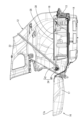
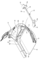
本発明の実施例である車両荷室構造が採用された車両を、図1から図5に示す。図2,図4,図5は、本車両10の荷室まわりを斜め後方側からの視点において示す図である。また、図2から図5においては、荷室の後方側に開閉可能に設けられたバックドアや、荷室の左側の側壁部を構成するデッキサイドトリムも図示を省略し、本車両10の荷室を構成するための内装材として、荷室の右側の側壁部を構成するデッキサイドトリム12、荷室の後端を形成するフィニッシュプレート(後方仕切り部材)13、荷室の底面側に設置されたトランクボックス14を示している。なお、本車両10は、セカンドシート16を有する車両であり、セカンドシート16は、シートバック17を前側に倒してシートバック17の背面17aを略水平な状態にできるようになっている。つまり、本車両10は、セカンドシート16上の空間を含む運転席および助手席の後方側の空間を、荷室として機能させることが可能となっている。
A vehicle employing a vehicle luggage compartment structure according to an embodiment of the present invention is shown in Figs. 1 to 5. Figs. 2, 4, and 5 are views showing the luggage compartment and surroundings of the
本実施例の車両荷室構造は、図5に示すように、複数の収納空間を有するトランクボックス14の上側に載置可能な概して矩形状の第1デッキボード18を備えている。本車両10は、この図5に示す仕様においては、荷室を広く確保すること等を目的として、第1デッキボード18の上面18aが、図3にも示すように、セカンドシート16のシートバック17の背面17aの高さより低い位置に載置される構成となっている。
As shown in FIG. 5, the vehicle luggage compartment structure of this embodiment is equipped with a generally rectangular
一方で、車室内にフラットなスペースを広く確保したいという要望もある。本車両10は、そのような要望に応えるべく、本発明の実施例である車両用第2デッキ構築セット20を設置可能とされ、その車両用第2デッキ構築セット20を設置することで、本発明の実施例の車両荷室構造が実現される。つまり、本車両10は、図5に示す第1デッキボード18上の第1デッキに加えて、図1から図4に示すように、車両用第2デッキ構築セット20によって第2デッキを設けることが可能となっている。以下に、その車両用第2デッキ構築セット20について詳しく説明することとする。
On the other hand, there is also a demand for a large flat space inside the vehicle cabin. In order to meet such demands, the
本車両用第2デッキ構築セット20(以下、単に「デッキ構築セット20」と呼ぶ場合がある。)は、第2デッキボード22と、その第2デッキボード22の前方側を支持する前方側支持体24と、第2デッキボード22の後方側を支持する後方側支持体26と、後方側支持体26を保持する一対のサイドボード(保持部材)28と、を含んで構成される。本デッキ構築セット20は、一対のサイドボード28,前方側支持体24,後方側支持体26,第2デッキボード22の順で設置することで、第2デッキが構築される。以下に、その順で、それぞれの構成要素の特徴および機能について、詳しく説明する。
This second deck construction set 20 for a vehicle (hereinafter sometimes simply referred to as "deck construction set 20") comprises a
まず、一対のサイドボード28は、デッキサイドトリム12上に載置される。詳しく言えば、左右のデッキサイドトリム12の各々には、図5に示すように、荷室の側壁部12aのみでなく、第1デッキボード18の左右の各々に、第1デッキボード18の上面18aと面一となるフロア面12bが形成されており、サイドボード28は、そのフロア面12b上に載置される。なお、デッキサイドトリム12の側壁部12aは、車両10のホイールハウスを覆うようにして車室内側に膨出した膨出部12cを有しており、その膨出部12cの後方側に、車幅方向に広がる空間が存在し、フロア面12aは、その空間の床面を形成している。そして、サイドボード28は、床面を嵩上げするような部材であり、図1から図4,図6および図7に示すように、上面30の車室外側の外形が、デッキサイドトリム12の内面形状に倣う形で形成されて、デッキサイドトリム12との間に隙間なく接した状態で載置される。
First, the pair of
また、サイドボード28は、底面の車室内側の外縁32がフロア面12bの車室内側の外縁より車室外側に位置しており、デッキサイドトリム12のフロア面12bからはみ出さないように載置されている。一方、上面30の車室内側の外縁30aは、底面の車室内側の外縁32より車室内側に張り出しており、図7に示すように、車幅方向において、デッキサイドトリムトリム12のフロア面12bの車室内側の外縁とほぼ同じ位置に(僅かに外側に)位置している。この上面30の車室内側の外縁30aは、図1および図3に示すように、第2デッキボード22が載置された場合に、その第2デッキボード22の車幅方向における外縁に当接して、第2デッキボード22の車幅方向のずれを防止する。
The
また、サイドボード28は、図6および図8に示すように、車室内側の壁面部34が、複数の柱部34aの間を車室内側から抉ったような形状とされており、第1デッキボード18上の空間が車幅方向に広げられている。また、図8に示すように、サイドボード28の裏面は、抉った形状を利用して、複数のリブ36が形成されており、十分な剛性が確保されている。
As shown in Figures 6 and 8, the
次に、前方側支持体24について説明する。前方側支持体24は、図9から図11に示すように、車幅方向に延びる長手状のフロントリンフォース(前方側支柱部材)40と、そのフロントリンフォース40の両端部の各々に固定された一対のフロントブラケット(前方側ブラケット)42と、を含んで構成される。一対のフロントブラケット42は、図11に示すように、金属製のブラケット本体44と、そのブラケット本体44を覆う樹脂製のブラケットカバー45と、からなる。それら一対のフロントブラケット42は、左右のデッキサイドトリム12の各々に取り付けられる。具体的には、図5に示すように、膨出部12cには、荷室の荷物を引っ掛けるフックを取り付けるための取付部12dが設けられており、フロントブラケット42は、その取付部12dを利用して、デッキサイドトリム12に固定される。より詳しく言えば、左右のフロントブラケット42の各々のブラケット本体44が、取付部12dにボルト46によって締結され、それらブラケット本体44の上に、フロントリンフォース40が渡されて、ボルト・ナット47によって固定される。そして、フロントリンフォース40の端部とブラケット本体44とを、上方から覆うようにブラケットカバー45を被せてクリップ48で固定されている。
Next, the
なお、ブラケットカバー45には、後方に延び出した部分に下方に向かって突出する爪部が設けられており、その爪部が、サイドボード28に形成された嵌合孔28aに嵌合する構造とされている。そのような構造により、前方側支持体24は、フロア面12bに載置しただけのサイドボード28の前端を固定するものとなっている。
The
前方側支持体24は、上記のような構造でデッキサイドトリム12に固定されており、載置された第2デッキボード22をしっかりと支持することができる。また、図9から図11に示すように、ブラケットカバー45は、車室外側の外縁に沿って前後方向に延びる立壁部45aと、平面視で三角形状の凸部45bと、を有する形状とされている。一方、第2デッキボード22は、図1等に示したように、前端部が前方に向かうほど車幅方向の寸法が小さくなる形状とされ、前端部の左右の端部の各々が前後方向に対して傾斜する傾斜部22aとなっている。これらにより、第2デッキボード22が前方側支持体24上に載置されると、図12に示すように、傾斜部22aがブラケットカバー45の凸部に接する状態となり、また、傾斜部22aから連続する第2デッキボード22の車幅方向における外縁が立壁部45aに当接する状態となる。したがって、前方側支持体24は、載置された第2デッキボード22を、前方側へのずれと、車幅方向へのずれを防止する状態で支持することができる。なお、凸部45bの高さは、第2デッキボード22の厚みとほぼ等しくされており、第2デッキボード22上面と凸部45bの上面とが面一とされている。
The
また、前方側支持体24は、図4および図13に示すように、第2デッキボード22を起き上がらせた状態、詳しく言えば、第2デッキボード22の後方側が持ち上げられた起立姿勢で支持することができる。つまり、前方側支持体24は、自立状態支持構造を有していると考えることができる。その自立状態支持構造は、上述した第2デッキボード22の前端部が前方ほど狭幅となる形状を利用するものである。詳しく言えば、ブラケットカバー45には、図9から図11に示すように、概して車幅方向に延びて、上方および車室内側に開口する嵌合溝45cが形成されている。その嵌合溝45cは、底面が車室内側に向かって下降するように傾斜するとともに、深さ方向において、下方ほど前方に向かって傾斜した形状となっている。つまり、第2デッキボード22の前端を、その嵌合溝45cに対して、下方かつ前方に向かって挿入することで、第2デッキボード22の傾斜部22aが嵌合溝45cの底面に当接することになる。また、その状態において、第2デッキボード22は、幅の小さくされた前端がフロントリンフォース40の下側に入り込むことになる。そして、ユーザーが第2デッキボード22から手を離せば、図14に示すように、第2デッキボード22は、上面がフロントリンフォース40に当接するとともに、下面が嵌合溝45cの車両後方側の面に当接することで、起立姿勢で支持されるようになっている。
As shown in Figs. 4 and 13, the
次いで、後方側支持体26について説明する。後方側支持体26は、図15,図16に示すように、車幅方向に延びる長手状のリアリンフォース(後方側支柱部材)50と、そのリアリンフォース50の両端部の各々に固定された一対のリアブラケット(後方側ブラケット)52と、を含んで構成される。この後方側支持体26は、図6および図7に示す一対のサイドボード28の各々の後方側に形成された凹所28bに、一対のリアブラケット52の各々が嵌り合うようにして、載置することが可能となっている。そして、後方側支持体26が一対のサイドボード28に対して載置された状態において、リアブラケット52の上面は、サイドボード28の上面30と面一となる。一方、リアリンフォース50は、リアブラケット52に対して、上面がリアブラケット52の上面から第2デッキボード22の厚み分だけ低くなる位置に固定されている。つまり、第2デッキボード22が載置された場合に、図2および図3に示すように、第2デッキボード22の上面が、リアブラケット52の上面およびサイドボード28の上面30と面一となり、荷室内の略全域にわたってフラットなスペースが形成されるのである。なお、リアブラケット52は、サイドボード28の凹所28bに対して載せ置かれるだけの構成とされており、図17に示すように、後方側支持体26は、容易に着脱することが可能とされている。
Next, the
なお、第2デッキボード22は、図1および図2に示すように、フィニッシュプレート13の形状に合わせて、後端が後方に膨らんだ湾曲状の湾曲部22bとされている。一方で、リアリンフォース50は直線状のものであるため、第2デッキボード22の後端側の湾曲部22bは、リアリンフォース50の後方に飛び出すことになる。そのため、湾曲部22bに上方から力が加わると、載せ置いただけの第2デッキボード22は、湾曲部が下がることでリアリンフォース50を支点として前方側が浮き上がって、外れてしまう虞がある。それに対して、本実施例では、図1,図15~図17に示すように、リアリンフォース50は、車幅方向中央に後方に突出したストライカ(湾曲部支持部)54が設けられており、湾曲部22bに上方から加わった力に対向することができ、第2デッキボード22のがたつきを防止することができる。ちなみに、第2デッキボード22は、左右対称形状とされて、裏返しても載置できるものであり、裏面側は樹脂材料の基材のままであるのに対して、表面側はカーペット素材が貼着されたものとなっている。
1 and 2, the
また、本実施例においては、後方側支持体26が、第2デッキボード22の後方側の部分に上方から加わった力を、しっかりと支持することができる構造となっている。具体的には、図15および図16に示すように、リアブラケット52は、後方に向かって突出した突出部52aを有しており、後方側支持体26がサイドボード28に載置された状態において、突出部52aが、フィニッシュプレート13に上下方向に重畳する位置まで延び出して、フィニッシュプレート13の上方から当接する当接部として機能するようになっている。したがって、第2デッキボード22に加わる上方の力は、後方側支持体26を介して、サイドボード28およびフィニッシュプレート13に分散され、本実施例の車両荷室構造によれば、第2デッキボード22をしっかりと支持することができる。
In addition, in this embodiment, the
以上のように、本実施例のデッキ構築セット20を設置することで、前倒ししたシートバック17の背面17aより低い位置に設けられた第1デッキボード18の上方側に、シートバック17の背面17aと同じ高さの第2デッキボード22が設置された荷室構造、つまり、本発明の車両荷室構造が実現することとなり、シートバック17の背面17a上と第2デッキボード22を主体とする第2デッキとによって、比較的大きなフラットなスペースを車室内に形成することが可能となる。なお、本実施例のデッキ構築セット20は、図5に示した元の車両荷室構造に対して、なんらの加工を施すことなく、第2デッキを構築することができるものとなっている。また、本実施例の車両荷室構造は、第1デッキボード18下の収納空間だけでなく、第1デッキボード18と第2デッキボード22との間に形成された収納空間を有しており、換言すれば、収納空間が2つの階層に区分されており、収納の自由度が高いものとなっている。
As described above, by installing the deck construction set 20 of this embodiment, a luggage compartment structure in which the
次に、本車両用第2デッキ構築セット20によって実現された本実施例の車両荷室構造の他の機能について説明する。先にも述べたように、本車両荷室構造は、第1デッキボード18の上には、第2デッキ構築セット20のいずれの部品も、載せ置かれていない。また、図7および図17等に示すように、一対のサイドボード28の間隔より、第1デッキボード18の車幅方向の寸法が僅かに小さくされている。換言すれば、第1デッキボード18は、第2デッキボード22と車幅方向の寸法が略同じとされ、上面視で、車幅方向において第2デッキボード22の内側に納まる構造とされている。そして、後方側支持体26は、容易に着脱することが可能とされているため、後方側支持体26を取り外せば、図18および図19に示すように第1デッキボード18をそれの前端を起点として起き上がらせることや、取り外すことが可能となる。したがって、第2デッキボード22が第1デッキボード18の上方に位置していても、第1デッキボード18の下の収納空間を有効に活用することができる。
Next, other functions of the vehicle luggage compartment structure of this embodiment realized by the second deck construction set 20 for the vehicle will be described. As described above, in this vehicle luggage compartment structure, none of the components of the second deck construction set 20 are placed on the
また、本実施例における車両10には、荷室の上方を覆うためのトノカバー装置60を備えている。そのトノカバー装置60は、可撓性を有するシート状のトノカバー本体62と、そのトノカバー本体62を巻き取る軸部とそれを収容するケースとからなる巻取り部64とを含んで構成される、巻取り式のトノカバー装置である。そのトノカバー装置60を利用している状態は示していないが、図3等には、トノカバー装置60の巻取り部64を取り付けるため取付凹部66および引き出したトノカバー本体62の後端を係止させる係止溝68が図示されている。なお、第1デッキボード18の下には、そのトノカバー装置60を収納するスペースは設けられていない。そして、本車両荷室構造は、車両用第2デッキ構築セット20がそのトノカバー装置60を収容可能となっている。
The
具体的には、図20~22に示すように、一対のサイドボード28の各々に、トノカバー装置60の両端部の各々を収容するトノカバー収容部70が設けられている。そのトノカバー収容部70は、図21および図22に示すように、車室内側に開口して上下方向に延びる溝状に形成されたものである。また、トノカバー収容部70は、上部が凹所28bに連続しており、上方にも開口するものとなっている。さらに、トノカバー収容部70の下部は、サイドボード28のほぼ下端まで延びている。なお、巻取り部64の両端部の各々は、弾性部材によって、長手方向外側に向かって付勢されており、長手方向に突っ張った状態で、自身を保持できる。したがって、トノカバー装置60は、一対のサイドボード28の各々のトノカバー収容部70に対して、車幅方向に延びる状態で上方から挿入されて、両端部の各々が外側に向かって付勢した状態で収納でき、上下方向におけるどの高さ位置にも収納することができるのである。つまり、図22に示したように、第1デッキボード18上に載せ置くような状態で、トノカバー装置60を収容するだけでなく、図23に示すように、荷物72が第1デッキボード18上に収容している状態においても、その荷物72の上方に収容することも可能である。
Specifically, as shown in Figs. 20 to 22, a pair of
また、本実施例における車両10は、車両の仕様によって、デッキサイドトリム12に対して第1デッキボード18を設置する高さが異なり、図24および図25に示す高さ位置となる。なお、前述したように、本車両用第2デッキ構築セット20は、一対のデッキサイドトリム12に対して設置しているため、上記のような仕様の違いがあったとしても、同様に設置することができる。そして、トノカバー収容部70が上下方向に延びる溝状に形成されているため、いずれの仕様であっても、図24および図25に示すように、トノカバー装置60を収容することができる。
In addition, in the
10…車両、12…デッキサイドトリム、12a…側壁部、12b…フロア面、12c…膨出部、13…フィニッシュプレート〔後方仕切り部材〕、17…シートバック、17a…背面、18…第1デッキボード、18a…上面、20…車両用第2デッキ構築セット、22…第2デッキボード、22a…傾斜部、22b…湾曲部、24…前方側支持体、26…後方側支持体、28…サイドボード〔保持体〕、40…フロントリンフォース〔前方側支柱部材〕、42…フロントブラケット〔前方側ブラケット〕、50…リアリンフォース〔後方側支柱部材〕、52…リアブラケット〔後方側ブラケット〕、52a…突出部〔当接部〕、54…ストライカ〔湾曲部支持部〕、60…トノカバー、70…トノカバー収容部 10...vehicle, 12...deck side trim, 12a...side wall, 12b...floor surface, 12c...bulge, 13...finish plate (rear partition member), 17...seat back, 17a...back, 18...first deck board, 18a...upper surface, 20...vehicle second deck construction set, 22...second deck board, 22a...inclined portion, 22b...curved portion, 24...front support, 26...rear support, 28...side board (retainer), 40...front reinforcement (front support member), 42...front bracket (front bracket), 50...rear reinforcement (rear support member), 52...rear bracket (rear bracket), 52a...projection (contact portion), 54...striker (curved portion support portion), 60...tonneau cover, 70...tonneau cover storage portion
Claims (11)
前記第1デッキボードの上方に重畳する位置で、前倒しした前記シートバックの前記背面と同じ高さ位置に設置可能な第2デッキボードと、
車幅方向に延びる姿勢で配され、前記第2デッキボードの後方側を支持する後方側支持体と、
前記第1デッキボードの左右の各々に位置して上方を向くフロア面の上に設置され、前記後方側支持体の両端部の各々を保持する一対の保持部材と、
を備え、
前記後方側支持体は、長手状で前記第2デッキボードが載せ置かれる後方側支柱部材と、前記後方側支柱部材の両端部の各々に固定されて前記一対の保持部材の各々に係合するための一対の後方側ブラケットと、を含んで構成され、前記一対の保持部材に対して着脱可能とされた車両荷室構造。 A first deck board is provided behind a seat back that can be folded forward until the back surface of the seat back is substantially horizontal, and is installed at a height lower than the back surface of the seat back when folded forward;
A second deck board that can be installed at the same height as the back surface of the seat back when tilted forward in a position overlapping above the first deck board;
a rear support body that is disposed in a position extending in the vehicle width direction and supports a rear side of the second deck board;
a pair of holding members that are located on left and right sides of the first deck board, respectively, and that are installed on an upwardly facing floor surface and hold both ends of the rear support;
Equipped with
The rear support body includes a longitudinal rear support member on which the second deck board is placed, and a pair of rear brackets fixed to both ends of the rear support member for engaging with each of the pair of retaining members, and is detachable from the pair of retaining members .
前記後方仕切り部材は、上端が前記第2デッキボードより低い高さのものとされており、
前記一対の後方側ブラケットの各々は、前記後方仕切り部材の上方に向かって延び出して前記後方仕切り部材に上方から当接する当接部を有する請求項1に記載の車両荷室構造。 The vehicle luggage compartment structure includes a rear partition member that is erected at the rear of the luggage compartment to partition the rear end of the luggage compartment,
The rear partition member has an upper end that is lower than the second deck board,
2. The vehicle luggage compartment structure according to claim 1 , wherein each of the pair of rear side brackets has an abutment portion that extends toward the upper side of the rear partition member and abuts against the rear partition member from above.
前記一対の後方側ブラケットの各々は、上面が前記一対の保持部材の上面と面一となる形状とされた請求項1または請求項2に記載の車両荷室構造。 Each of the pair of retaining members has an upper surface that is flush with an upper surface of the second deck board,
3. The vehicle luggage compartment structure according to claim 1 , wherein an upper surface of each of the pair of rear brackets is flush with upper surfaces of the pair of holding members.
前記後方側支持体は、前記前方側支持体の後方において車幅方向に延びる姿勢で配され、
当該車両荷室構造は、前記左右の側壁部の各々が車両のホイールハウスを覆うように車室内側に膨出した膨出部を有し、
前記前方側支持体は、前記左右の側壁部の各々の前記膨出部の間に配され、
前記一対の保持部材の各々は、前記膨出部の後方側で前記第2デッキボードの左右の各々の空間を埋めるとともに、上面が前記第2デッキボードの上面と面一となる形状とされている請求項1から請求項4のいずれか一項に記載の車両荷室構造。 a front support body that is held against left and right side wall portions in a vehicle interior in a position extending in a vehicle width direction and supports a front side of the second deck board ,
The rear support is disposed rearward of the front support and extends in a vehicle width direction,
In the vehicle luggage compartment structure, each of the left and right side wall portions has a bulging portion bulging into the vehicle cabin so as to cover a wheel house of the vehicle,
the front support body is disposed between the bulging portions of the left and right side wall portions,
5. The vehicle luggage compartment structure according to claim 1, wherein each of the pair of retaining members fills a space on either side of the second deck board rearward of the bulging portion and has an upper surface that is flush with an upper surface of the second deck board .
前記前方側支持体は、前記第2デッキボードの後方側が持ち上げられた起立姿勢で支持するための自立状態支持構造を有する請求項1から請求項5のいずれか1項に記載の車両荷室構造。 a front support body that is held against left and right side wall portions in a vehicle interior in a position extending in a vehicle width direction and supports a front side of the second deck board,
6. The vehicle luggage compartment structure according to claim 1, wherein the front support body has a free-standing support structure for supporting the second deck board in an upright position with a rear side of the second deck board raised.
前記前方側支持体は、長手状で前記第2デッキボードが載せ置かれる前方側支柱部材と、前記前方側支柱部材の両端部の各々に固定されて前記左右の側壁部の各々に取り付けるための一対の前方側ブラケットと、を含んで構成され、
前記一対の前方側ブラケットの各々は、上方側に開口して前記第2デッキボードの前記傾斜部が嵌り合う嵌合溝を有し、
前記自立状態支持構造は、前記第2デッキボードの前記前端部を前記前方側支柱部材の下方側に入り込ませるとともに、前記傾斜部の各々を前記一対の前方側ブラケットの前記嵌合溝に嵌合させることで、前記第2デッキボードを前記起立姿勢で支持する構造とされた請求項6に記載の車両荷室構造。 The second deck board has a shape in which a dimension in a vehicle width direction becomes smaller toward the front of a front end portion, and each of the left and right sides of the front end portion is an inclined portion,
the front support body includes a longitudinal front support member on which the second deck board is placed, and a pair of front brackets fixed to both ends of the front support member and for attachment to the left and right side wall portions,
each of the pair of front brackets has a fitting groove that opens upward and into which the inclined portion of the second deck board fits;
7. The vehicle luggage compartment structure according to claim 6, wherein the self-supporting support structure is configured to support the second deck board in the upright position by inserting the front end of the second deck board below the front support member and fitting each of the inclined portions into the fitting grooves of the pair of front brackets.
前記後方側支持体には、車幅方向中央に、後方に延び出して前記第2デッキボードの前記湾曲部を支持する湾曲部支持部が設けられている請求項1から請求項9のいずれか1項に記載の車両荷室構造。 the second deck board has a rear end formed as a curved portion that bulges rearward, and is supported by the rear support with the curved portion protruding rearward from the rear support,
10. The vehicle luggage compartment structure according to claim 1, wherein the rear support body is provided with a curved portion support portion at a center in a vehicle width direction, the curved portion support portion extending rearward and supporting the curved portion of the second deck board.
第2デッキボードと、
車幅方向に延びる姿勢で車室内の左右の側壁部に対して保持され、前記第2デッキボードの前方側を支持する前方側支持体と、
前記前方側支持体の後方において車幅方向に延びる姿勢で配され、前記第2デッキボードの後方側を支持する後方側支持体と、
前記第1デッキボードの左右の各々に位置して上方を向くフロア面の上に設置され、前記後方側支持体の両端部の各々を保持する一対の保持部材と、
を含んで構成され、
前記後方側支持体は、長手状で前記第2デッキボードが載せ置かれる後方側支柱部材と、前記後方側支柱部材の両端部の各々に固定されて前記一対の保持部材の各々に係合するための一対の後方側ブラケットと、を含んで構成され、前記一対の保持部材に対して着脱可能とされた車両用第2デッキ構築セット。 A second deck construction set for a vehicle is provided for a luggage compartment of a vehicle, the first deck being mainly composed of a first deck board that is provided behind a seat back that can be folded forward until the back of the seat back is substantially horizontal and is installed at a height lower than the back of the seat back when folded forward, the second deck construction set being for constructing a second deck above the first deck at the same height as the back of the seat back when folded forward,
A second deck board;
a front support body that is held against left and right side wall portions inside the vehicle cabin in a position extending in the vehicle width direction and supports a front side of the second deck board;
a rear support disposed behind the front support and extending in the vehicle width direction, the rear support supporting a rear side of the second deck board;
a pair of holding members that are located on the left and right sides of the first deck board, respectively, and that are installed on an upwardly facing floor surface and hold both ends of the rear support;
The present invention relates to a method for manufacturing a computer-implemented ...
The rear support body includes a longitudinal rear support member on which the second deck board is placed, and a pair of rear brackets fixed to both ends of the rear support member for engaging with each of the pair of retaining members, and the second deck construction set for a vehicle is detachable from the pair of retaining members .
Priority Applications (2)
| Application Number | Priority Date | Filing Date | Title |
|---|---|---|---|
| JP2021148713A JP7680921B2 (en) | 2021-09-13 | 2021-09-13 | Vehicle cargo compartment structure and second deck construction set for vehicle |
| JP2025077296A JP7808726B2 (en) | 2021-09-13 | 2025-05-07 | Vehicle cargo compartment structure and vehicle second deck construction set |
Applications Claiming Priority (1)
| Application Number | Priority Date | Filing Date | Title |
|---|---|---|---|
| JP2021148713A JP7680921B2 (en) | 2021-09-13 | 2021-09-13 | Vehicle cargo compartment structure and second deck construction set for vehicle |
Related Child Applications (1)
| Application Number | Title | Priority Date | Filing Date |
|---|---|---|---|
| JP2025077296A Division JP7808726B2 (en) | 2021-09-13 | 2025-05-07 | Vehicle cargo compartment structure and vehicle second deck construction set |
Publications (2)
| Publication Number | Publication Date |
|---|---|
| JP2023041372A JP2023041372A (en) | 2023-03-24 |
| JP7680921B2 true JP7680921B2 (en) | 2025-05-21 |
Family
ID=85641658
Family Applications (2)
| Application Number | Title | Priority Date | Filing Date |
|---|---|---|---|
| JP2021148713A Active JP7680921B2 (en) | 2021-09-13 | 2021-09-13 | Vehicle cargo compartment structure and second deck construction set for vehicle |
| JP2025077296A Active JP7808726B2 (en) | 2021-09-13 | 2025-05-07 | Vehicle cargo compartment structure and vehicle second deck construction set |
Family Applications After (1)
| Application Number | Title | Priority Date | Filing Date |
|---|---|---|---|
| JP2025077296A Active JP7808726B2 (en) | 2021-09-13 | 2025-05-07 | Vehicle cargo compartment structure and vehicle second deck construction set |
Country Status (1)
| Country | Link |
|---|---|
| JP (2) | JP7680921B2 (en) |
Citations (5)
| Publication number | Priority date | Publication date | Assignee | Title |
|---|---|---|---|---|
| JP2002532334A (en) | 1998-12-22 | 2002-10-02 | ダイムラークライスラー コーポレイション | Vehicle shelves with multiple positions |
| JP2008143435A (en) | 2006-12-13 | 2008-06-26 | Kasai Kogyo Co Ltd | Floor board structure of automobile |
| JP2009292195A (en) | 2008-06-03 | 2009-12-17 | Mazda Motor Corp | Rear luggage compartment structure of vehicle |
| JP2014028536A (en) | 2012-07-31 | 2014-02-13 | Mazda Motor Corp | Cargo chamber structure for vehicle |
| JP2016203935A (en) | 2015-04-28 | 2016-12-08 | ダイハツ工業株式会社 | Cargo room structure of vehicle |
Family Cites Families (3)
| Publication number | Priority date | Publication date | Assignee | Title |
|---|---|---|---|---|
| JPH09104271A (en) * | 1995-10-11 | 1997-04-22 | Central Motor Co Ltd | Flat deck structure |
| EP2522550B1 (en) * | 2011-05-11 | 2014-01-22 | Fiat Group Automobiles S.p.A. | Trunk of a motor vehicle |
| JP6473678B2 (en) * | 2015-09-07 | 2019-02-20 | 林テレンプ株式会社 | Cargo compartment structure |
-
2021
- 2021-09-13 JP JP2021148713A patent/JP7680921B2/en active Active
-
2025
- 2025-05-07 JP JP2025077296A patent/JP7808726B2/en active Active
Patent Citations (5)
| Publication number | Priority date | Publication date | Assignee | Title |
|---|---|---|---|---|
| JP2002532334A (en) | 1998-12-22 | 2002-10-02 | ダイムラークライスラー コーポレイション | Vehicle shelves with multiple positions |
| JP2008143435A (en) | 2006-12-13 | 2008-06-26 | Kasai Kogyo Co Ltd | Floor board structure of automobile |
| JP2009292195A (en) | 2008-06-03 | 2009-12-17 | Mazda Motor Corp | Rear luggage compartment structure of vehicle |
| JP2014028536A (en) | 2012-07-31 | 2014-02-13 | Mazda Motor Corp | Cargo chamber structure for vehicle |
| JP2016203935A (en) | 2015-04-28 | 2016-12-08 | ダイハツ工業株式会社 | Cargo room structure of vehicle |
Also Published As
| Publication number | Publication date |
|---|---|
| JP2025105971A (en) | 2025-07-10 |
| JP7808726B2 (en) | 2026-01-29 |
| JP2023041372A (en) | 2023-03-24 |
Similar Documents
| Publication | Publication Date | Title |
|---|---|---|
| CA2424766C (en) | Hybrid pick up box | |
| US7017980B1 (en) | Vehicle load floor | |
| US8128146B2 (en) | Trunk box structure of automobile | |
| JP3275685B2 (en) | Luggage compartment structure | |
| US7281742B2 (en) | Vehicle compartment divider | |
| CN116135674B (en) | Panel storage and two-tier loading system | |
| JPH10297542A (en) | Car rear floor structure | |
| JP5929636B2 (en) | Car luggage compartment structure | |
| JP7680921B2 (en) | Vehicle cargo compartment structure and second deck construction set for vehicle | |
| KR102506240B1 (en) | Roof box for vehicles | |
| JP2019038305A (en) | Luggage room structure for vehicle | |
| JP7127237B2 (en) | Vehicle luggage compartment structure | |
| JP2009292196A (en) | Rear luggage compartment structure of vehicle | |
| JPS6117694B2 (en) | ||
| JP5391180B2 (en) | Truck storage structure | |
| JP2014028538A (en) | Cargo chamber structure for vehicle | |
| JPH0334350Y2 (en) | ||
| JP4640638B2 (en) | Car luggage compartment structure | |
| US20260116306A1 (en) | Luggage storage structure | |
| JP4239777B2 (en) | Rear structure of the vehicle | |
| JP5108716B2 (en) | Bracket for vehicle | |
| JP2006143037A (en) | Vehicle rear part cargo chamber structure | |
| JP7347261B2 (en) | Tonneau cover locking structure | |
| JP3477438B2 (en) | Vehicle floor structure | |
| JP2002225633A (en) | Package tray structure for vehicles |
Legal Events
| Date | Code | Title | Description |
|---|---|---|---|
| A621 | Written request for application examination |
Free format text: JAPANESE INTERMEDIATE CODE: A621 Effective date: 20240311 |
|
| A977 | Report on retrieval |
Free format text: JAPANESE INTERMEDIATE CODE: A971007 Effective date: 20241114 |
|
| A131 | Notification of reasons for refusal |
Free format text: JAPANESE INTERMEDIATE CODE: A131 Effective date: 20241119 |
|
| A521 | Request for written amendment filed |
Free format text: JAPANESE INTERMEDIATE CODE: A523 Effective date: 20250115 |
|
| TRDD | Decision of grant or rejection written | ||
| A01 | Written decision to grant a patent or to grant a registration (utility model) |
Free format text: JAPANESE INTERMEDIATE CODE: A01 Effective date: 20250410 |
|
| A61 | First payment of annual fees (during grant procedure) |
Free format text: JAPANESE INTERMEDIATE CODE: A61 Effective date: 20250509 |
|
| R150 | Certificate of patent or registration of utility model |
Ref document number: 7680921 Country of ref document: JP Free format text: JAPANESE INTERMEDIATE CODE: R150 |