JP7680964B2 - Track construction machine and method for compacting tracks - Google Patents
Track construction machine and method for compacting tracks Download PDFInfo
- Publication number
- JP7680964B2 JP7680964B2 JP2021569536A JP2021569536A JP7680964B2 JP 7680964 B2 JP7680964 B2 JP 7680964B2 JP 2021569536 A JP2021569536 A JP 2021569536A JP 2021569536 A JP2021569536 A JP 2021569536A JP 7680964 B2 JP7680964 B2 JP 7680964B2
- Authority
- JP
- Japan
- Prior art keywords
- track
- image
- compaction
- construction machine
- detected
- Prior art date
- Legal status (The legal status is an assumption and is not a legal conclusion. Google has not performed a legal analysis and makes no representation as to the accuracy of the status listed.)
- Active
Links
Images




Classifications
-
- E—FIXED CONSTRUCTIONS
- E01—CONSTRUCTION OF ROADS, RAILWAYS, OR BRIDGES
- E01B—PERMANENT WAY; PERMANENT-WAY TOOLS; MACHINES FOR MAKING RAILWAYS OF ALL KINDS
- E01B27/00—Placing, renewing, working, cleaning, or taking-up the ballast, with or without concurrent work on the track; Devices therefor; Packing sleepers
- E01B27/12—Packing sleepers, with or without concurrent work on the track; Compacting track-carrying ballast
- E01B27/13—Packing sleepers, with or without concurrent work on the track
- E01B27/16—Sleeper-tamping machines
-
- E—FIXED CONSTRUCTIONS
- E01—CONSTRUCTION OF ROADS, RAILWAYS, OR BRIDGES
- E01B—PERMANENT WAY; PERMANENT-WAY TOOLS; MACHINES FOR MAKING RAILWAYS OF ALL KINDS
- E01B2203/00—Devices for working the railway-superstructure
- E01B2203/10—Track-lifting or-lining devices or methods
-
- E—FIXED CONSTRUCTIONS
- E01—CONSTRUCTION OF ROADS, RAILWAYS, OR BRIDGES
- E01B—PERMANENT WAY; PERMANENT-WAY TOOLS; MACHINES FOR MAKING RAILWAYS OF ALL KINDS
- E01B2203/00—Devices for working the railway-superstructure
- E01B2203/12—Tamping devices
-
- E—FIXED CONSTRUCTIONS
- E01—CONSTRUCTION OF ROADS, RAILWAYS, OR BRIDGES
- E01B—PERMANENT WAY; PERMANENT-WAY TOOLS; MACHINES FOR MAKING RAILWAYS OF ALL KINDS
- E01B2203/00—Devices for working the railway-superstructure
- E01B2203/16—Guiding or measuring means, e.g. for alignment, canting, stepwise propagation
-
- E—FIXED CONSTRUCTIONS
- E01—CONSTRUCTION OF ROADS, RAILWAYS, OR BRIDGES
- E01B—PERMANENT WAY; PERMANENT-WAY TOOLS; MACHINES FOR MAKING RAILWAYS OF ALL KINDS
- E01B27/00—Placing, renewing, working, cleaning, or taking-up the ballast, with or without concurrent work on the track; Devices therefor; Packing sleepers
- E01B27/12—Packing sleepers, with or without concurrent work on the track; Compacting track-carrying ballast
- E01B27/13—Packing sleepers, with or without concurrent work on the track
- E01B27/16—Sleeper-tamping machines
- E01B27/17—Sleeper-tamping machines combined with means for lifting, levelling or slewing the track
Landscapes
- Engineering & Computer Science (AREA)
- Architecture (AREA)
- Civil Engineering (AREA)
- Structural Engineering (AREA)
- Machines For Laying And Maintaining Railways (AREA)
Description
本発明は、バラスト道床内に支持され、レールが固定されたまくらぎを有する軌道を突き固めるための軌道工事機械であって、レール走行装置にて走行可能な機械フレームと、バラスト道床内に沈込み可能、振動可能かつ互いに接近可能な突固めツールを有する突固めユニットと、を備え、作業方向で見て突固めユニットよりも前方に、リアルタイム撮像を出力装置に伝送するためのカメラが配置されている、軌道工事機械に関する。さらに、本発明は、軌道工事機械を運転するための方法に関する。 The present invention relates to a track construction machine for compacting a track supported in a ballast bed and having sleepers with rails fixed thereto, the track construction machine comprising a machine frame capable of running on a rail travelling device, and a compaction unit having compaction tools capable of sinking into the ballast bed, vibrating and approaching each other, and a camera for transmitting real-time images to an output device is disposed ahead of the compaction unit as viewed in the working direction. Furthermore, the present invention relates to a method for operating the track construction machine.
国際公開第2018/206214号に基づき、冒頭に記載した軌道工事機械が公知である。この公知の軌道工事機械は、突固め過程を遠隔制御可能に実施するための支援システムを具備している。この支援システムでは、リアルタイム撮像を運転室内の表示装置に伝送するために、カメラが機械の作業ユニットに向けられている。これによって、作業ユニットを視認する固有の作業室を配置する必要がなくなる。この場合、カメラの画像区分は、このような作業室内にいるオペレータの視野にほぼ対応している。 From WO 2018/206214, the aforementioned track construction machine is known. The known track construction machine is equipped with an assistance system for remotely controllably carrying out the compaction process. In this assistance system, a camera is directed at the working unit of the machine in order to transmit real-time images to a display device in the driver's cab. This makes it unnecessary to provide a separate work station for viewing the working unit. In this case, the image section of the camera corresponds approximately to the field of view of an operator in such a work station.
本発明の根底にある課題は、冒頭に記載した形態の軌道工事機械に対して、突固めユニットの遠隔制御を可能にするためのリアルタイム撮像を改善することである。さらに、相応の軌道工事機械を運転するための改善された方法が提供されることが望ましい。 The problem underlying the present invention is to provide improved real-time imaging for track construction machines of the type described at the beginning, in order to enable remote control of the compaction unit. Furthermore, it is desirable to provide an improved method for operating a corresponding track construction machine.
本発明によれば、これらの課題は、請求項1および9の特徴によって解決される。本発明の有利な改良形態は、従属請求項から明らかである。
According to the invention, these problems are solved by the features of
本発明では、作業方向で見て突固めユニットよりも前方に、軌道の第1の表面範囲を第1の画像区分として検出するための第1のカメラシステムが配置されており、作業方向で見て突固めユニットよりも後方に、軌道の第2の表面範囲を第2の画像区分として検出するための第2のカメラシステムが配置されており、検出された複数の画像区分が、互いに部分的に交わっており、出力装置が、複数の画像区分を1つの合成画像で出力するように構成されている。このようなビデオシステムを配置することによって、突固めユニットの下方に位置する軌道の支障のないリアルタイム撮像がオペレータに提供される。突固めユニットの構成要素により前方のカメラシステムの画像区分内で覆い隠されてしまっている軌道の領域は、後方のカメラシステムの画像区分内に検出される。その逆も然りで、前方のカメラシステムは、後方のカメラシステムに対して覆われてしまっている領域を検出する。カメラシステムの取付け箇所および方向設定と、突固めユニットとの幾何学的な関係から、合成画像内で突固めユニットの位置も把握される。したがって、出力装置が、突固めユニットの瞬時の位置に対する、瞬時に突き固めるべき軌道領域の広範囲の画像をオペレータに提供する。これらのリアルタイム情報によって、突固めユニットを遠隔で効率よく各々のまくらぎの上方に位置決めすることができ、突固めサイクルを実施することができる。 In the present invention, a first camera system is arranged in front of the compaction unit in the working direction for detecting a first surface area of the track as a first image section, and a second camera system is arranged behind the compaction unit in the working direction for detecting a second surface area of the track as a second image section, the detected image sections partially intersect with each other, and the output device is configured to output the image sections in one composite image. By arranging such a video system, an uninterrupted real-time imaging of the track located below the compaction unit is provided to the operator. Areas of the track that are obscured in the image section of the front camera system by components of the compaction unit are detected in the image section of the rear camera system. Vice versa, the front camera system detects areas that are obscured with respect to the rear camera system. The position of the compaction unit is also known in the composite image due to the mounting and orientation of the camera systems and the geometric relationship with the compaction unit. The output device thus provides the operator with a comprehensive image of the track area to be compacted at the moment relative to the momentary position of the compaction unit. With this real-time information, compaction units can be remotely and efficiently positioned above each sleeper to carry out the compaction cycle.
この解決手段の改良形態は、突固めユニットが、変位駆動装置によってカメラシステムに対して変位可能に配置されており、出力装置が、突固めユニットの瞬時の位置を表示するように構成されていることを特定している。このためには、例えば、変位駆動装置の変位量が連続的に記録され、評価される。このことは、例えば、作業方向または作業方向に対して横方向への突固めユニットの変位と、鉛直軸線を中心とした突固めユニットの回動とに当てはまる。 A refinement of this solution specifies that the compaction unit is arranged displaceably relative to the camera system by means of a displacement drive and that the output device is configured to display the instantaneous position of the compaction unit. For this purpose, for example, the displacement of the displacement drive is continuously recorded and evaluated. This applies, for example, to the displacement of the compaction unit in the working direction or transversely to the working direction and to the rotation of the compaction unit about a vertical axis.
本発明の有利な発展形態では、カメラシステムが、斜め下向きに方向設定されたカメラ軸線を有しており、コンピュータユニットが、検出された画像区分の歪みを除去するように構成されている。斜めのカメラ軸線によって、覆われてしまう領域なしに、より大きな画像区分の検出が可能となる。この発展形態では、実施された歪み除去によって、合成画像内に、上方から見た軌道の実際の全体表示が得られる。 In an advantageous development of the invention, the camera system has a camera axis oriented obliquely downwards, and the computer unit is configured to undistort the detected image segments. The oblique camera axis allows the detection of larger image segments without covered areas. In this development, the implemented distortion undistortion results in a real overall representation of the trajectory as seen from above in the composite image.
更なる改善形態は、各々のカメラシステムが、分割画像区分を検出するための、機械横方向に相並んで配置された少なくとも2つのカメラを備えており、相並んで配置された2つのカメラの分割画像区分が、互いに交わっており、出力装置が、全ての分割画像区分を合成するように構成されていることを特定している。この配置形態では、覆われてしまう領域なしに、付加的な画像内容が提供される。これによって、合成画像の情報容量が高められる。さらに、より長い焦点距離を有するカメラ光学系を使用することができる。これによって、歪み誤差を回避するための手間が減少する。 A further refinement specifies that each camera system comprises at least two cameras arranged side by side in the cross machine direction for detecting the split image segments, the split image segments of the two side by side cameras intersect with each other, and the output device is configured to combine all the split image segments. In this arrangement, additional image content is provided without covered areas, which increases the information capacity of the combined image. Furthermore, camera optics with a longer focal length can be used, which reduces the effort required to avoid distortion errors.
本発明の改良形態では、軌道の検出された表面範囲内に、下方に向けられた光線によって、特に照明パターンの形態の光マーキングを発生させるための照明装置が配置されている。この光マーキングは合成画像内に認めることができ、オペレータに付加的な位置情報を提供する。 In a refinement of the invention, an illumination device is arranged in the detected surface area of the trajectory for generating a light marking, in particular in the form of an illumination pattern, by means of a downwardly directed light beam. This light marking can be seen in the composite image and provides the operator with additional position information.
太陽光の直接入射による撮像クオリティへのマイナスの影響を回避するために、カメラシステムが、赤外光を検出するように構成されており、軌道の検出すべき表面範囲を照明するために、少なくとも1つの赤外光源が配置されていると有利である。このとき、場合により発生させる光マーキングのためにも、赤外光源が使用される。 In order to avoid negative effects on the image quality due to direct incidence of sunlight, it is advantageous if the camera system is configured to detect infrared light and at least one infrared light source is arranged for illuminating the surface area of the track to be detected. In this case, an infrared light source is also used for the light marking that may be generated.
有利な拡張形態は、作業方向で見て第1のカメラシステムよりも前方に、まくらぎ位置を検出するためのセンサ装置が配置されていることを特定している。このようなセンサシステムは、突固めユニットの遠隔操作時の付加的な補助位置をオペレータに提供する。 An advantageous extension specifies that a sensor device for detecting the sleeper position is arranged ahead of the first camera system in the working direction. Such a sensor system provides the operator with an additional auxiliary position during remote control of the compaction unit.
このとき、出力装置が、検出されたまくらぎ位置を合成画像内に表示するために、センサ装置に接続されていると有利である。例えば、結像されたまくらぎが、デジタルマーキングによって画定されている。これによって、突固めユニットの位置決め時の確実性が高められる。 In this case, it is advantageous if an output device is connected to the sensor device in order to display the detected sleeper positions in the composite image. For example, the imaged sleepers are defined by digital marking. This increases the reliability when positioning the compaction unit.
有利には、突固めツールの瞬時の高さ位置を検出するために、突固めユニットの側方に並んで少なくとも1つのカメラが付加的に配置されている。こうして、バラスト道床内への突固めツールの押込み深さも遠隔制御することができる。 Advantageously, at least one camera is additionally arranged next to the side of the compaction unit in order to detect the instantaneous height position of the compaction tool. In this way, the penetration depth of the compaction tool into the ballast bed can also be controlled remotely.
軌道工事機械を運転するための本発明に係る方法では、合成画像が、出力装置によってオペレータに対してリアルタイムで表示され、突固めユニットが、合成画像を使用して軌道に対して位置決めされる。上方から見た軌道の画像によって、突固めツールを各々のまくらぎ区画の上方に簡単に位置決めすることができる。 In the method of the present invention for operating a track construction machine, a composite image is displayed to the operator in real time by an output device, and the compaction unit is positioned relative to the track using the composite image. The image of the track from above allows the compaction tool to be easily positioned above each sleeper section.
方法の有利な改良形態では、突固めユニットの瞬時の位置が検出され、これに基づき得られる突固めツールの突込み箇所が、合成画像内に表示される。有利には、センサとコンピュータユニットとによって、軌道に対する、下側の突固めツール端部に配置された突固めピッケルの瞬時の位置が求められ、合成画像内に表示される。このことは、特に変位可能または回動可能な突固めユニットの場合ならびに旋回可能な突固めピッケルの使用時に有利である。これによって、突固めピッケルが沈込み動作時にどの箇所でバラスト道床内に突き込まれるのかが、オペレータに対してリアルタイムで表示される。 In an advantageous refinement of the method, the instantaneous position of the compaction unit is detected and the resulting plunge point of the compaction tool is displayed in the composite image. Advantageously, the sensor and the computer unit determine the instantaneous position of the compaction pick arranged at the end of the lower compaction tool relative to the track and display it in the composite image. This is particularly advantageous in the case of displaceable or rotatable compaction units as well as when using a swivelling compaction pick. This shows the operator in real time where the compaction pick is plunged into the ballast bed during the plunge operation.
方法の別の改善形態は、軌道の検出された表面範囲に照明装置によって光マーキングを発生させることを特定している。このようなマーキングによって、例えば、突固めユニットの瞬時の位置を表示することができる。 Another refinement of the method specifies the generation of light markings by means of a lighting device on the detected surface area of the track. By means of such markings, for example, the instantaneous position of the compaction unit can be indicated.
さらに、照明装置によって照明パターンを発生させ、この照明パターンのマッチングによって画像区分が合成されると有利である。こうして、複数の画像区分の簡単な繋ぎ合わせ(スティッチング)を実施することができる。 Furthermore, it is advantageous if a lighting device generates a lighting pattern and image segments are combined by matching the lighting patterns. In this way, simple stitching of multiple image segments can be performed.
カメラシステムの検出された画像データから、軌道の検出された表面範囲の三次元画像を算出する有利な方法拡張形態によって、更なる可能性が提供される。これによって、出力装置を用いて、バラスト道床、まくらぎおよびレールの深さ情報を含んだ、軌道の三次元のリアルタイムモデルが表示可能となる。 Further possibilities are provided by an advantageous method extension in which a three-dimensional image of the detected surface area of the track is calculated from the detected image data of the camera system. This makes it possible to display a three-dimensional real-time model of the track, including the depth information of the ballast bed, sleepers and rails, by means of an output device.
まくらぎの上方への突固めユニットの位置決めは、軌道工事機械の前進時にセンサ装置によってまくらぎ位置が検出され、このまくらぎ位置が、オペレータに対して合成画像内に表示される場合に容易となる。リアルタイム情報のこの強化によって、光状況が悪い場合でも確実な操作が可能となる。例えば、まくらぎは画像内に、着色された輪郭でマーキングされている。 Positioning the compaction unit above the sleepers is made easier if the sleeper position is detected by a sensor device as the track construction machine advances and is displayed to the operator in the composite image. This enhancement of real-time information allows reliable operation even in poor light conditions. For example, the sleepers are marked in the image with a colored outline.
オペレータの付加的な負担軽減は、突固め位置が、支援システムによって予め設定され、提案された突固め位置が、オペレータに対して合成画像内に表示される場合に達成される。この場合、突固めユニットの位置決めは、突固めツールの瞬時の位置を、提案された突固め位置に合致させるように行われる。 Additional relief for the operator is achieved if the compaction position is predefined by the assistance system and the proposed compaction position is displayed to the operator in the composite image. In this case, the positioning of the compaction unit is performed in such a way that the instantaneous position of the compaction tool corresponds to the proposed compaction position.
以下に、本発明を添付の図面を参照しながら例示的に説明する。 The present invention will now be described by way of example with reference to the accompanying drawings.
図1に示した軌道工事機械1は突固め機械であり、レール走行装置2にて走行可能な機械フレーム3を備えている。この機械フレーム3には、突固めユニット4が配置されている。突固め機械は、軌道5を処理する働きをする。この軌道5では、まくらぎ6に固定されたレール7がバラスト道床8内に支持されている。軌道工事機械1は付加的な機能を有していてもよい。機械1は、例えば、バラスト清掃のための清掃装置または軌道安定化のための安定化ユニットを備えている。
The track construction machine 1 shown in FIG. 1 is a compaction machine and has a
突固め過程では、まくらぎ6とレール7とから形成された軌框が、扛上/整正ユニット9と検測システム10とによって目標位置に持ち上げられ、場合により側方に移動させられる。この位置を固定するために、振動する突固めツール11が、下側の端部に配置された突固めピッケル12でもってバラスト道床8内に押し込まれる。押し込まれた突固めピッケル12は互いに接近し、このとき、持ち上げられたまくらぎ6の下側のバラストを締め固める。
During the compaction process, the track frame formed by the
作業方向13で見て、突固めユニット4よりも前方に第1のカメラシステム14が配置され、突固めユニット4よりも後方に第2のカメラシステム15が配置されている。両方のカメラシステム14,15は出力装置16に接続されている。この出力装置16は、軌道工事機械1の運転室17内に格納されている。この運転室17内では、操作装置18が操作要素によって、突固めユニット4を遠隔制御するように構成されている。具体的には、機械制御装置19を介して、軌道工事機械1のユニット4,9の種々の駆動装置と走行駆動装置とが操作可能となる。
When viewed in the working
作業方向13で見て第1のカメラシステム14よりも前方には、任意選択的に、まくらぎ位置を検出するためのセンサ装置20が配置されている。このセンサ装置20は、例えば、表面輪郭を検出するための回転式レーザスキャナ21と、レール固定部を検知するための渦電流センサ22とを備えている。センサ信号を合成することによって、各々のまくらぎ6の位置が正確に検出可能となる。
Optionally, a sensor device 20 for detecting the sleeper position is arranged ahead of the
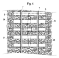
図2および図3には、カメラシステム14,15の例示的な配置形態が示してある。第1のカメラシステム14によって、軌道5の第1の表面範囲23が第1の画像区分24,25として検出される(図4)。第2のカメラシステム15は、軌道5の第2の表面範囲26を第2の画像区分27,28として検出する。このときに重要となるのは、画像区分24,25,27,28が互いに部分的に交わっており、これによって、部分的に同じ画像内容を有していることである。
2 and 3 show an exemplary arrangement of the
画像区分24,25,27,28は出力装置16内で合成されて、突固めユニット4の下側に位置する軌道5の1つの画像29が作成される。このように複数の画像区分24,25,27,28を合成して1つの全体画像29を作成することは、スティッチングとも呼ばれる。これはリアルタイム撮像の出力であるので、オペレータは、合成画像29をベースにして突固めユニット4を制御することができる。この場合には、突固めプロセスの動特性を検出するために、十分に高いフレームレートが予め設定されている。
The
図5では、出力装置16のモニタウィンドウ内に、図4に示した画像区分24,25,27,28の合成画像29が示してある。各々の表面範囲24,26には、それぞれ2つの分割画像区分24,25;27,28が割り当てられている。図3において明らかであるように、これらの分割画像区分24,25;27,28を検出するための各々のカメラシステム14,15は、機械横方向に相並んで配置された2つのカメラ30を有している。欠損なしのスティッチングのために、各々のカメラシステム14,15の分割画像区分24,25;27,28は互いに交わっている。
5 shows a
軌道5が突固めユニット4の構成要素によって覆われてしまうことを最小限に抑えるために、カメラ30が、斜め下向きに方向設定されたカメラ軸線31を有していると有利である(図2)。これに伴う画像区分24,25,27,28の歪みは、コンピュータユニットによって除去される。例えば、各々のカメラまたは各々のカメラシステム14,15は、1つの固有のコンピュータユニットを有している。また、画像区分24,25,27,28の歪み除去のために、1つの共通のコンピュータユニットも使用可能である。
In order to minimize the obscuration of the track 5 by the components of the compaction unit 4, it is advantageous if the
例えば、高解像度と高被写界深度とを有するビデオカメラ30が使用される。ビデオデータはリアルタイムで処理され、合成画像29として出力装置16に表示される。ビデオデータを効率よく圧縮することによって、作業過程を文書化するための大きな手間なしに、ビデオデータを記憶することができる。
For example, a
突固めユニット4の遠隔制御は、照明装置32が配置されていると容易になる。この照明装置32は、下方に向けられた光線によって、検出された表面範囲23,26の内側に光マーキング33を発生させる。このとき、この光マーキング33が照明パターンを生じさせると有利である。照明装置32の光線は、有利には、突固めユニット4の対称軸線34に沿って方向設定されている。こうして、対称軸線34が1つのまくらぎ6の上に位置していると、オペレータに対して付加的に表示される。さらに、光マーキング33は、画像区分24,25,27,28をスティッチングするために使用可能である。照明装置32の発光体として、例えば、いわゆる平行光LEDが使用可能である。
Remote control of the compaction unit 4 is facilitated if a
センサ装置20が存在している場合には、検知されたまくらぎ位置が付加的に判っている。検知されたまくらぎ6に対する突固めユニット4の相対的な位置は、センサ装置20の配置と、機械フレーム3への突固めユニット4の配置との間の既知の幾何学的な関係から明らかとなる。出力装置16への接続によって、まくらぎ6の位置が合成画像29内にマーキング35によって表示される。こうして、まくらぎ6が部分的にバラストによって覆われてしまっている場合でも、オペレータは、まくらぎ6に対する突固めユニット4の瞬時の位置を認識する。
If the sensor device 20 is present, the detected sleeper position is additionally known. The relative position of the compaction unit 4 with respect to the detected
提案された突固め位置を合成画像29内に表示するために、出力装置16が、突固め位置を予め設定するための支援システムに接続されていると、オペレータに課せられる要求がさらに減少する。例えば、センサ装置20によって、軌道内の支障物が検知され、支援システムが、相応に適合された突固め位置をオペレータに提案する。いずれにせよ、合成画像29内に、突固めユニット4の位置から瞬時に得られる、バラスト道床8内への突固めピッケル12の突込み箇所36が表示されると有利である。その後、この表示された突込み箇所36を、場合により、提案された突固め位置に合致させる。
The demands on the operator are further reduced if the
有利には、出力装置16が、付加的な情報を表示するように構成されている。図5において明らかであるように、例えば、まくらぎ6の側方に区間データ37が表示される。別のウィンドウには、軌道工事機械1の突固めユニット4または別の装置の状態データ38が記載されている。この表示補足により、オペレータにとって、広範囲の概観と、誤差発生に対する迅速な対応とが可能になる。
Advantageously, the
複数のまくらぎ6の下側を同時に突き固めるためのまくらぎ多丁突固めユニット39では、個々の集合ユニット40同士の間に付加的なカメラ30が配置されていると有利である(図6)。こうして、まくらぎ多丁突固めユニット39の下側に位置する軌道の合成画像29を作成するために、付加的な分割画像区分24,25,27,28が提供される。さらに、各々の集合ユニット40の上方には、相応の対称軸線34をマーキングするための照明装置32が配置されている。
In a
Claims (14)
作業方向(13)で見て前記突固めユニット(4)よりも前方に、前記軌道(5)の第1の表面範囲(23)を第1の画像区分(24,25)として検出するための第1のカメラシステム(14)が配置されており、作業方向(13)で見て前記突固めユニット(4)よりも後方に、前記軌道(5)の第2の表面範囲(26)を第2の画像区分(27,28)として検出するための第2のカメラシステム(15)が配置されており、検出された複数の前記画像区分(24,25,27,28)は、互いに部分的に交わっており、前記出力装置(16)は、複数の前記画像区分(24,25,27,28)を1つの合成画像で出力するように構成されており、
前記軌道(5)の検出された前記表面範囲(23,26)内に、下方に向けられた光線によって、特に照明パターンの形態の光マーキング(33)を発生させるための照明装置(32)が配置されていることを特徴とする、軌道工事機械(1)。 A track construction machine (1) for compacting a track (5) supported in a ballast bed (8) and having sleepers (6) with rails (7) fixed thereto, the track construction machine (1) comprising: a machine frame (3) capable of running on rail running gear (2); and a compaction unit (4) having compaction tools (11) capable of sinking in the ballast bed (8), vibrating and approaching each other, the track construction machine (1) comprising: a camera (30) for transmitting real-time image capture to an output device (16) disposed ahead of the compaction unit (4) as viewed in a working direction (13);
a first camera system (14) is arranged ahead of the compaction unit (4) in the working direction (13) for detecting a first surface area (23) of the track (5) as a first image section (24, 25) and a second camera system (15) is arranged behind the compaction unit (4) in the working direction (13) for detecting a second surface area (26) of the track (5) as a second image section (27, 28), the detected image sections (24, 25, 27, 28) partially intersect with one another, and the output device (16) is configured to output the image sections (24, 25, 27, 28) in one composite image ,
A track construction machine (1), characterized in that within the detected surface area (23, 26) of the track (5) an illumination device (32) is arranged for generating a light marking (33), in particular in the form of an illumination pattern, by means of a downwardly directed light beam.
前記合成画像(29)を前記出力装置(16)によってオペレータに対してリアルタイムで表示し、前記突固めユニット(4)を、前記合成画像(29)を使用して前記軌道(5)に対して位置決めすることを特徴とする、方法。 A method for operating a track construction machine (1) according to any one of claims 1 to 7 ,
displaying said composite image (29) in real time to an operator by said output device (16), and positioning said compaction unit (4) relative to said trajectory (5) using said composite image (29).
Applications Claiming Priority (3)
| Application Number | Priority Date | Filing Date | Title |
|---|---|---|---|
| ATA194/2019A AT522455B1 (en) | 2019-05-23 | 2019-05-23 | Track construction machine and method for tamping a track |
| ATA194/2019 | 2019-05-23 | ||
| PCT/EP2020/061271 WO2020233934A1 (en) | 2019-05-23 | 2020-04-23 | Track-building machine and method for tamping a track |
Publications (2)
| Publication Number | Publication Date |
|---|---|
| JP2022534699A JP2022534699A (en) | 2022-08-03 |
| JP7680964B2 true JP7680964B2 (en) | 2025-05-21 |
Family
ID=70456773
Family Applications (1)
| Application Number | Title | Priority Date | Filing Date |
|---|---|---|---|
| JP2021569536A Active JP7680964B2 (en) | 2019-05-23 | 2020-04-23 | Track construction machine and method for compacting tracks |
Country Status (11)
| Country | Link |
|---|---|
| US (1) | US12442140B2 (en) |
| EP (1) | EP3973104B1 (en) |
| JP (1) | JP7680964B2 (en) |
| CN (1) | CN113853462B (en) |
| AT (1) | AT522455B1 (en) |
| AU (1) | AU2020280667B2 (en) |
| BR (1) | BR112021023504A2 (en) |
| CA (1) | CA3135554A1 (en) |
| EA (1) | EA202100251A1 (en) |
| WO (1) | WO2020233934A1 (en) |
| ZA (1) | ZA202107773B (en) |
Families Citing this family (4)
| Publication number | Priority date | Publication date | Assignee | Title |
|---|---|---|---|---|
| JP2022162253A (en) * | 2021-04-12 | 2022-10-24 | Jimテクノロジー株式会社 | Image processing system for tunnel excavator and image processing method for tunnel excavator |
| AT525332B1 (en) * | 2021-08-04 | 2025-10-15 | Hp3 Real Gmbh | Procedure for correcting the lateral distance and the height distance of a platform edge to the track axis |
| CN116695501B (en) * | 2023-08-07 | 2023-12-15 | 中国铁建高新装备股份有限公司 | Methods, devices, electronic equipment, and storage media for detecting railway switches |
| AT528557A1 (en) | 2024-07-22 | 2026-02-15 | Hp3 Real Gmbh | Method for remote control of several simultaneously operating track-mounted maintenance machines |
Citations (10)
| Publication number | Priority date | Publication date | Assignee | Title |
|---|---|---|---|---|
| US20020078853A1 (en) | 2000-12-22 | 2002-06-27 | Quentin Holmes | Range-finding based image processing rail way servicing apparatus and method |
| JP2004301619A (en) | 2003-03-31 | 2004-10-28 | Railway Technical Res Inst | Image reading device |
| US20060032063A1 (en) | 2004-08-16 | 2006-02-16 | Fabrication Technology Associates, Inc., Also Known As Fab Tech | Method and system for controlling railroad surfacing |
| CN101982609A (en) | 2010-09-19 | 2011-03-02 | 北京凌云光视数字图像技术有限公司 | Tamping wagon photoelectric measurement system and method |
| CN205105334U (en) | 2015-11-09 | 2016-03-23 | 长沙慧联智能科技有限公司 | Tamping car local and long -range video monitoring and voice -data system |
| JP2016208294A (en) | 2015-04-23 | 2016-12-08 | 株式会社日立製作所 | Multiple-image photographing system, photographing apparatus, and image processing apparatus |
| US20170029001A1 (en) | 2014-04-15 | 2017-02-02 | Eber Dynamics Ab | Method and apparatus to determine structural parameters of a railway track |
| US20170096783A1 (en) | 2015-10-05 | 2017-04-06 | Harsco Technologies LLC | Light reference system |
| WO2018206214A1 (en) | 2017-05-12 | 2018-11-15 | Plasser & Theurer Export Von Bahnbaumaschinen Gmbh | Method for controlling a track construction machine |
| JP2018197058A (en) | 2017-05-23 | 2018-12-13 | 株式会社交通建設 | Railway track obstacle data measurement system and obstacle obstacle investigation machine |
Family Cites Families (17)
| Publication number | Priority date | Publication date | Assignee | Title |
|---|---|---|---|---|
| AT321347B (en) * | 1968-01-02 | 1975-03-25 | Plasser Bahnbaumasch Franz | Mobile track tamping machine |
| AT359110B (en) | 1977-08-16 | 1980-10-27 | Plasser Bahnbaumasch Franz | SELF-DRIVE TRACKING MACHINE ARRANGEMENT |
| JPH0617562B2 (en) | 1988-10-03 | 1994-03-09 | 西日本旅客鉄道株式会社 | Marutai's automatic controller |
| JP2525093B2 (en) * | 1991-09-10 | 1996-08-14 | 東海旅客鉄道株式会社 | Obstacle position detection method for track maintenance vehicles |
| JPH05328054A (en) | 1992-05-19 | 1993-12-10 | Fuji Xerox Co Ltd | Image reader |
| JP3380587B2 (en) * | 1993-05-13 | 2003-02-24 | 株式会社トキメック | Track structure identification device |
| JPH10197455A (en) * | 1997-01-09 | 1998-07-31 | Ricoh Co Ltd | Surface defect inspection equipment |
| CN2340801Y (en) * | 1997-12-24 | 1999-09-29 | 铁道部株洲电力机车研究所 | Automatic spreading, leveling and vibrating vehicle |
| EP1001085B1 (en) * | 1998-11-11 | 2004-12-01 | Franz Plasser Bahnbaumaschinen-Industriegesellschaft m.b.H. | Method and apparatus for tamping a railway track |
| BRPI0512871A (en) * | 2004-06-30 | 2008-04-08 | Georgetown Rail Equipment Comp | system and method for inspecting railroad |
| CN201794010U (en) * | 2010-09-19 | 2011-04-13 | 北京凌云光视数字图像技术有限公司 | Photoelectric measuring system for tamping car |
| RU2468136C1 (en) * | 2011-03-30 | 2012-11-27 | Максим Николаевич Балезин | Method for railway track sleeper tamping and machine for its realisation |
| AT13635U1 (en) * | 2013-01-10 | 2014-05-15 | Swietelsky Baugesellschaft M B H | Device for plugging the ballast bed of a track system |
| JP6322707B2 (en) | 2013-07-16 | 2018-05-09 | 富士通株式会社 | Learning recommendation simulation system and method |
| EP2960371B1 (en) | 2014-06-27 | 2017-08-09 | HP3 Real GmbH | Device for measuring tracks |
| AT518839B1 (en) | 2016-07-11 | 2018-12-15 | Plasser & Theurer Exp Von Bahnbaumaschinen G M B H | System and method for measuring a track |
| CN108195472B (en) | 2018-01-08 | 2020-03-20 | 亿嘉和科技股份有限公司 | Heat conduction panoramic imaging method based on track mobile robot |
-
2019
- 2019-05-23 AT ATA194/2019A patent/AT522455B1/en active
-
2020
- 2020-04-23 JP JP2021569536A patent/JP7680964B2/en active Active
- 2020-04-23 BR BR112021023504A patent/BR112021023504A2/en active IP Right Grant
- 2020-04-23 EP EP20721205.1A patent/EP3973104B1/en active Active
- 2020-04-23 EA EA202100251A patent/EA202100251A1/en unknown
- 2020-04-23 WO PCT/EP2020/061271 patent/WO2020233934A1/en not_active Ceased
- 2020-04-23 AU AU2020280667A patent/AU2020280667B2/en active Active
- 2020-04-23 CA CA3135554A patent/CA3135554A1/en active Pending
- 2020-04-23 CN CN202080037641.8A patent/CN113853462B/en active Active
- 2020-04-23 US US17/605,091 patent/US12442140B2/en active Active
-
2021
- 2021-10-13 ZA ZA2021/07773A patent/ZA202107773B/en unknown
Patent Citations (10)
| Publication number | Priority date | Publication date | Assignee | Title |
|---|---|---|---|---|
| US20020078853A1 (en) | 2000-12-22 | 2002-06-27 | Quentin Holmes | Range-finding based image processing rail way servicing apparatus and method |
| JP2004301619A (en) | 2003-03-31 | 2004-10-28 | Railway Technical Res Inst | Image reading device |
| US20060032063A1 (en) | 2004-08-16 | 2006-02-16 | Fabrication Technology Associates, Inc., Also Known As Fab Tech | Method and system for controlling railroad surfacing |
| CN101982609A (en) | 2010-09-19 | 2011-03-02 | 北京凌云光视数字图像技术有限公司 | Tamping wagon photoelectric measurement system and method |
| US20170029001A1 (en) | 2014-04-15 | 2017-02-02 | Eber Dynamics Ab | Method and apparatus to determine structural parameters of a railway track |
| JP2016208294A (en) | 2015-04-23 | 2016-12-08 | 株式会社日立製作所 | Multiple-image photographing system, photographing apparatus, and image processing apparatus |
| US20170096783A1 (en) | 2015-10-05 | 2017-04-06 | Harsco Technologies LLC | Light reference system |
| CN205105334U (en) | 2015-11-09 | 2016-03-23 | 长沙慧联智能科技有限公司 | Tamping car local and long -range video monitoring and voice -data system |
| WO2018206214A1 (en) | 2017-05-12 | 2018-11-15 | Plasser & Theurer Export Von Bahnbaumaschinen Gmbh | Method for controlling a track construction machine |
| JP2018197058A (en) | 2017-05-23 | 2018-12-13 | 株式会社交通建設 | Railway track obstacle data measurement system and obstacle obstacle investigation machine |
Also Published As
| Publication number | Publication date |
|---|---|
| AU2020280667B2 (en) | 2025-05-22 |
| AU2020280667A1 (en) | 2021-10-28 |
| EP3973104C0 (en) | 2025-11-19 |
| US20220186444A1 (en) | 2022-06-16 |
| EA202100251A1 (en) | 2022-03-14 |
| AT522455A4 (en) | 2020-11-15 |
| AT522455B1 (en) | 2020-11-15 |
| CN113853462B (en) | 2024-07-12 |
| EP3973104A1 (en) | 2022-03-30 |
| ZA202107773B (en) | 2023-11-29 |
| BR112021023504A2 (en) | 2022-01-18 |
| JP2022534699A (en) | 2022-08-03 |
| CA3135554A1 (en) | 2020-11-26 |
| EP3973104B1 (en) | 2025-11-19 |
| CN113853462A (en) | 2021-12-28 |
| WO2020233934A1 (en) | 2020-11-26 |
| US12442140B2 (en) | 2025-10-14 |
Similar Documents
| Publication | Publication Date | Title |
|---|---|---|
| JP7680964B2 (en) | Track construction machine and method for compacting tracks | |
| AU625749B2 (en) | Reference system for railway track machines | |
| CN206029901U (en) | Train overhaul machine people | |
| CN101109957A (en) | Automatic driving control method and system for large engineering vehicles | |
| JPH05202506A (en) | Measurement vehicle | |
| GB2093308A (en) | On-track equipment for lateral track position measurement | |
| KR102423399B1 (en) | Multi-camera type tunnel scanning apparatus, driving-type tunnel scanning system and tunnel surface investing method | |
| JP5763974B2 (en) | Progress measurement device, progress measurement system, and progress measurement method | |
| CN110258273A (en) | A kind of full-automatic road surface repairing device and method for repairing road surface | |
| CN109459440A (en) | A kind of railway contact line supporting mechanism defects detection imaging system | |
| CN206952357U (en) | Weld seam tracking sensor | |
| CN215561586U (en) | Steel rail weld joint recognition system and normalizing equipment | |
| JP4893063B2 (en) | Ground element position shift measuring method, apparatus, and program | |
| CN116660282A (en) | A method and system for detecting defects on a track surface | |
| JPH08276269A (en) | Copy welding method | |
| JPH08281435A (en) | Copy welding method and apparatus | |
| CN113250020A (en) | Steel rail weld joint recognition system and normalizing equipment | |
| JP3464902B2 (en) | Groove copying machine | |
| EA041696B1 (en) | TRACK MACHINE AND METHOD FOR RAIL TRACK TAMPING | |
| JP2024520563A (en) | Assembly and method for optically capturing a trajectory - Patents.com | |
| CN121298609B (en) | A non-destructive testing device for road asphalt surface quality | |
| JP2535268B2 (en) | Track center distance measuring method and apparatus | |
| JPH0510721A (en) | Target distance correction method, target, distance correction device, and excavation device using the distance correction device | |
| JP2002035933A (en) | Welding position automatic profiling control device | |
| JPH08276268A (en) | Copy welding method |
Legal Events
| Date | Code | Title | Description |
|---|---|---|---|
| A621 | Written request for application examination |
Free format text: JAPANESE INTERMEDIATE CODE: A621 Effective date: 20230421 |
|
| A977 | Report on retrieval |
Free format text: JAPANESE INTERMEDIATE CODE: A971007 Effective date: 20240216 |
|
| A131 | Notification of reasons for refusal |
Free format text: JAPANESE INTERMEDIATE CODE: A131 Effective date: 20240326 |
|
| A131 | Notification of reasons for refusal |
Free format text: JAPANESE INTERMEDIATE CODE: A131 Effective date: 20241002 |
|
| A521 | Request for written amendment filed |
Free format text: JAPANESE INTERMEDIATE CODE: A523 Effective date: 20241211 |
|
| TRDD | Decision of grant or rejection written | ||
| A01 | Written decision to grant a patent or to grant a registration (utility model) |
Free format text: JAPANESE INTERMEDIATE CODE: A01 Effective date: 20250410 |
|
| A61 | First payment of annual fees (during grant procedure) |
Free format text: JAPANESE INTERMEDIATE CODE: A61 Effective date: 20250509 |
|
| R150 | Certificate of patent or registration of utility model |
Ref document number: 7680964 Country of ref document: JP Free format text: JAPANESE INTERMEDIATE CODE: R150 |