JP7689331B2 - Shell-and-tube heat exchanger, refrigeration cycle device, and heat exchange method - Google Patents

Shell-and-tube heat exchanger, refrigeration cycle device, and heat exchange method Download PDF

Info

Publication number
JP7689331B2
JP7689331B2 JP2021027382A JP2021027382A JP7689331B2 JP 7689331 B2 JP7689331 B2 JP 7689331B2 JP 2021027382 A JP2021027382 A JP 2021027382A JP 2021027382 A JP2021027382 A JP 2021027382A JP 7689331 B2 JP7689331 B2 JP 7689331B2
Authority
JP
Japan
Prior art keywords
heat transfer
stage
transfer tube
liquid
plane
Prior art date
Legal status (The legal status is an assumption and is not a legal conclusion. Google has not performed a legal analysis and makes no representation as to the accuracy of the status listed.)
Active
Application number
JP2021027382A
Other languages
Japanese (ja)
Other versions
JP2022128910A (en
Inventor
道美 日下
Current Assignee (The listed assignees may be inaccurate. Google has not performed a legal analysis and makes no representation or warranty as to the accuracy of the list.)
Panasonic Intellectual Property Management Co Ltd
Original Assignee
Panasonic Intellectual Property Management Co Ltd
Priority date (The priority date is an assumption and is not a legal conclusion. Google has not performed a legal analysis and makes no representation as to the accuracy of the date listed.)
Filing date
Publication date
Application filed by Panasonic Intellectual Property Management Co Ltd filed Critical Panasonic Intellectual Property Management Co Ltd
Priority to JP2021027382A priority Critical patent/JP7689331B2/en
Priority to CN202180083940.XA priority patent/CN116583702A/en
Priority to EP21906349.2A priority patent/EP4265982A4/en
Priority to PCT/JP2021/044142 priority patent/WO2022130986A1/en
Publication of JP2022128910A publication Critical patent/JP2022128910A/en
Application granted granted Critical
Publication of JP7689331B2 publication Critical patent/JP7689331B2/en
Active legal-status Critical Current
Anticipated expiration legal-status Critical

Links

Images

Landscapes

  • Heat-Exchange Devices With Radiators And Conduit Assemblies (AREA)

Description

本開示は、シェルアンドチューブ式熱交換器、冷凍サイクル装置、及び熱交換方法に関する。 This disclosure relates to a shell-and-tube heat exchanger, a refrigeration cycle device, and a heat exchange method.

従来、伝熱管に向けて冷却水を散布することによって、伝熱管の内部の冷媒を冷却する技術が知られている。例えば、特許文献1には、冷凍システムに用いられる蒸発式凝縮器が記載されている。この蒸発式凝縮器は、ケーシング、冷媒冷却部、散水部、及び通風ファンを備えている。ケーシングは、空気吸込口と、空気排出口と、集水タンクとを備えている。冷媒冷却部は、複数の凝縮コイルを有し、冷媒を冷却して凝縮させる。散水部は、散水ノズルを有し、散水ノズルから凝縮コイルに向けて冷却水が散水される。 Conventionally, a technique is known for cooling the refrigerant inside a heat transfer tube by spraying cooling water toward the heat transfer tube. For example, Patent Document 1 describes an evaporative condenser used in a refrigeration system. This evaporative condenser includes a casing, a refrigerant cooling section, a water spray section, and a ventilation fan. The casing includes an air intake port, an air exhaust port, and a water collection tank. The refrigerant cooling section has multiple condensation coils and cools and condenses the refrigerant. The water spray section has a water spray nozzle, and cooling water is sprayed from the water spray nozzle toward the condensation coil.

国際公開第2017/073367号International Publication No. 2017/073367

本開示は、伝熱管群に向かってノズルから液体を噴霧するときに、ノズルに対して遠方の伝熱管の外面においてドライアウトを抑制する観点から有利なシェルアンドチューブ式熱交換器を提供する。 The present disclosure provides a shell-and-tube heat exchanger that is advantageous in terms of suppressing dryout on the outer surface of heat transfer tubes that are far from the nozzle when liquid is sprayed from the nozzle toward a group of heat transfer tubes.

本開示のシェルアンドチューブ式熱交換器は、
シェルと、
前記シェルの内部に配置された伝熱管群と、
前記伝熱管群に向かって液体を噴霧するノズルと、を備え、
前記伝熱管群は、第一平面に沿って配列された複数の伝熱管を有する第一段と、前記第一平面に平行な第二平面に沿って配列された複数の伝熱管を有し、かつ、前記第一平面に垂直な方向において前記第一段と隣り合っている第二段とを含み、
前記ノズルは、前記第一平面に垂直な方向において前記第一段の前記複数の伝熱管の前記第二段に近い第一端部と、前記第一平面に垂直な方向において前記第二段の前記複数の伝熱管の前記第一段に近い第二端部との間を通過する噴霧軸を有し、かつ、前記第一段と前記第二段との間を通過する扁平な噴霧パターンで前記液体を噴霧する。
The shell-and-tube heat exchanger of the present disclosure comprises:
A shell,
A heat transfer tube group disposed inside the shell;
a nozzle for spraying a liquid toward the heat transfer tube group,
the heat transfer tube group includes a first stage having a plurality of heat transfer tubes arranged along a first plane, and a second stage having a plurality of heat transfer tubes arranged along a second plane parallel to the first plane and adjacent to the first stage in a direction perpendicular to the first plane,
The nozzle has a spray axis that passes between a first end of the plurality of heat transfer tubes of the first stage that is close to the second stage in a direction perpendicular to the first plane and a second end of the plurality of heat transfer tubes of the second stage that is close to the first stage in a direction perpendicular to the first plane, and sprays the liquid in a flat spray pattern that passes between the first stage and the second stage.

また、本開示の熱交換方法は、
第一平面に沿って配列された複数の伝熱管を有する第一段と、前記第一平面に平行な第二平面に沿って配列された複数の伝熱管を有し、かつ、前記第一平面に垂直な方向において前記第一段と隣り合っている第二段とを含む伝熱管群の内部において熱媒体を通過させることと、
前記第一平面に垂直な方向において前記第一段の前記複数の伝熱管の前記第二段に近い第一端部と、前記第一平面に垂直な方向において前記第二段の前記複数の伝熱管の前記第一段に近い第二端部との間を通過する噴霧軸を有し、かつ、前記第一段と前記第二段との間を通過する扁平な噴霧パターンで前記伝熱管群に向かって液体を噴霧し、前記熱媒体と前記液体とを熱交換させることとを、含む。
The heat exchange method of the present disclosure further comprises:
a heat transfer medium is passed through a heat transfer tube group including a first stage having a plurality of heat transfer tubes arranged along a first plane, and a second stage having a plurality of heat transfer tubes arranged along a second plane parallel to the first plane and adjacent to the first stage in a direction perpendicular to the first plane;
spraying liquid toward the heat transfer tube group in a flat spray pattern having a spray axis passing between a first end portion of the plurality of heat transfer tubes of the first stage near the second stage in a direction perpendicular to the first plane and a second end portion of the plurality of heat transfer tubes of the second stage near the first stage in a direction perpendicular to the first plane, and passing between the first stage and the second stage, thereby performing heat exchange between the heat medium and the liquid.

本開示によれば、第一段の複数の伝熱管の第一端部と、第二段の複数の伝熱管の第二端部との間を通過する噴霧軸を有し、かつ、第一段と第二段との間を通過する扁平な噴霧パターンで伝熱管群に向かって液体を噴霧できる。そのため、本開示のシェルアンドチューブ式熱交換器及び熱交換方法は、ノズルから遠方の伝熱管の外面においてドライアウトを抑制する観点から有利である。 According to the present disclosure, liquid can be sprayed toward the heat transfer tube group in a flat spray pattern that has a spray axis passing between the first ends of the heat transfer tubes in the first stage and the second ends of the heat transfer tubes in the second stage and passes between the first stage and the second stage. Therefore, the shell-and-tube heat exchanger and heat exchange method disclosed herein are advantageous in terms of suppressing dryout on the outer surface of the heat transfer tubes far from the nozzle.

本開示の実施の形態1における冷凍サイクル装置の構成を示す図FIG. 1 is a diagram showing a configuration of a refrigeration cycle device according to a first embodiment of the present disclosure. 図1におけるII-II線を切断線とする蒸発器の縦断面図FIG. 2 is a vertical cross-sectional view of an evaporator taken along line II-II in FIG. ノズルから噴霧される液相冷媒の噴霧パターンを示す図FIG. 1 is a diagram showing a spray pattern of liquid refrigerant sprayed from a nozzle. ノズルから噴霧される液相冷媒の噴霧パターンを示す図FIG. 1 is a diagram showing a spray pattern of liquid refrigerant sprayed from a nozzle. 図1におけるIV-IV線を切断線とする蒸発器の縦断面図FIG. 4 is a vertical cross-sectional view of an evaporator taken along line IV-IV in FIG. 液相冷媒が噴霧される領域を示す図FIG. 1 shows an area where liquid refrigerant is sprayed. 液相冷媒の噴霧及び流動の状態を示す図FIG. 1 shows the spray and flow state of liquid refrigerant. 本開示の実施の形態2において液相冷媒が噴霧される領域を示す図FIG. 13 is a diagram showing an area where a liquid-phase refrigerant is sprayed in the second embodiment of the present disclosure. 本開示の実施の形態3において液相冷媒の噴霧及び流動の状態を示す図FIG. 13 is a diagram showing the spray and flow state of a liquid-phase refrigerant in the third embodiment of the present disclosure.

(本開示の基礎となった知見等)
本発明者が本開示を想到するに至った当時、シェルアンドチューブ式熱交換器において、ノズルを用いて冷却水等の液体を伝熱管に向かって噴霧することが試みられていた。そうした状況下において、本発明者は、ノズルから噴霧された液体の流れをヒントにして、シェルアンドチューブ式熱交換器の性能を高め得るという着想を得た。そして、本発明者は、その着想を実現するには、例えば、液相冷媒の噴霧パターンが円錐形状であると、ノズルに対して遠方の伝熱管の外面には霧状の液相冷媒が到達しにくくドライアウトが発生しやすいという課題があることを発見した。本発明者は、その課題を解決するために、本開示の主題を構成するに至った。
(The knowledge and other information that formed the basis of this disclosure)
At the time when the present inventor came up with the present disclosure, attempts had been made to spray liquid such as cooling water toward heat transfer tubes using a nozzle in a shell-and-tube heat exchanger. Under such circumstances, the present inventor got an idea that the performance of the shell-and-tube heat exchanger could be improved by taking a hint from the flow of liquid sprayed from the nozzle. The present inventor then discovered that in order to realize the idea, for example, if the spray pattern of the liquid-phase refrigerant is conical, the mist of liquid-phase refrigerant is unlikely to reach the outer surface of the heat transfer tube far from the nozzle, and dryout is likely to occur. In order to solve the problem, the present inventor came up with the subject of the present disclosure.

そこで、本開示は、伝熱管群に向かってノズルから液体を噴霧しつつ、ノズルに対して遠方の伝熱管の外面においてドライアウトを抑制する観点から有利なシェルアンドチューブ式熱交換器を提供する。 Therefore, the present disclosure provides a shell-and-tube heat exchanger that is advantageous in terms of suppressing dryout on the outer surface of heat transfer tubes that are far from the nozzle while spraying liquid from a nozzle toward a group of heat transfer tubes.

以下、図面を参照しながら、実施の形態を詳細に説明する。ただし、必要以上に詳細な説明は省略する場合がある。例えば、既によく知られた事項の詳細説明、又は、実質的に同一の構成に対する重複説明を省略する場合がある。これは、以下の説明が必要以上に冗長になるのを避け、当業者の理解を容易にするためである。 Below, the embodiments will be described in detail with reference to the drawings. However, more detailed explanation than necessary may be omitted. For example, detailed explanation of already well-known matters or duplicate explanation of substantially the same configuration may be omitted. This is to avoid the following explanation becoming unnecessarily redundant and to make it easier for those skilled in the art to understand.

なお、添付図面及び以下の説明は、当業者が本開示を十分に理解するために提供されるのであって、これらにより特許請求の範囲に記載の主題を限定することを意図していない。添付の図面において、X軸、Y軸、及びZ軸は互いに直交している。XZ平面は水平であり、Y軸負方向が重力方向である。 The accompanying drawings and the following description are provided to enable those skilled in the art to fully understand the present disclosure, and are not intended to limit the subject matter described in the claims. In the accompanying drawings, the X-axis, Y-axis, and Z-axis are mutually perpendicular. The XZ plane is horizontal, and the negative Y-axis direction is the direction of gravity.

(実施の形態1)
以下、図1から図6を用いて、実施の形態1を説明する。
(Embodiment 1)
Hereinafter, the first embodiment will be described with reference to FIG. 1 to FIG.

[1-1.構成]
図1は、シェルアンドチューブ式熱交換器を備えた冷凍サイクル装置100の構成を示している。図1に示す通り、冷凍サイクル装置100は、蒸発器101、圧縮機102、凝縮器103、流量弁104、流路110a、流路110b、流路110c、及び流路110dを備えている。蒸発器101の出口は、流路110aによって圧縮機102の入口に接続されている。圧縮機102の出口は、流路110bによって凝縮器103の入口に接続されている。凝縮器103の出口は、流路110cによって流量弁104の入口に接続されている。流量弁104の出口は、流路110dによって蒸発器101の入口に接続されている。流路110a及び110bは気相冷媒が通過する経路である。流路110c及び流路110dは液相冷媒が通過する経路である。各経路は、例えば、少なくとも1つの金属製の配管で構成されている。
[1-1. Configuration]
FIG. 1 shows the configuration of a refrigeration cycle apparatus 100 equipped with a shell-and-tube heat exchanger. As shown in FIG. 1, the refrigeration cycle apparatus 100 includes an evaporator 101, a compressor 102, a condenser 103, a flow valve 104, a flow path 110a, a flow path 110b, a flow path 110c, and a flow path 110d. The outlet of the evaporator 101 is connected to the inlet of the compressor 102 by the flow path 110a. The outlet of the compressor 102 is connected to the inlet of the condenser 103 by the flow path 110b. The outlet of the condenser 103 is connected to the inlet of the flow valve 104 by the flow path 110c. The outlet of the flow valve 104 is connected to the inlet of the evaporator 101 by the flow path 110d. The flow paths 110a and 110b are paths through which a gas-phase refrigerant passes. The flow paths 110c and 110d are paths through which a liquid-phase refrigerant passes. Each path is, for example, composed of at least one metal pipe.

蒸発器101において液相冷媒が加熱されて蒸発し、気相冷媒が生成される。気相冷媒は、圧縮機102に吸入されて圧縮される。圧縮された気相冷媒は圧縮機102から凝縮器103に供給される。気相冷媒は凝縮器103で冷却されて凝縮及び液化する。これにより、液相冷媒が生成される。液相冷媒は、流量弁104を経由して凝縮器103から蒸発器101に戻される。 In the evaporator 101, the liquid phase refrigerant is heated and evaporated to generate a gas phase refrigerant. The gas phase refrigerant is sucked into the compressor 102 and compressed. The compressed gas phase refrigerant is supplied from the compressor 102 to the condenser 103. The gas phase refrigerant is cooled in the condenser 103, where it is condensed and liquefied. This generates a liquid phase refrigerant. The liquid phase refrigerant is returned from the condenser 103 to the evaporator 101 via the flow valve 104.

冷凍サイクル装置100における冷媒は、特定の冷媒に限定されない。冷媒としては、フロン冷媒、低GWP(Global Warming Potential)冷媒、自然冷媒などが挙げられる。フロン冷媒としては、ハイドロクロロフルオロカーボン(HCFC)及びハイドロフルオロカーボン(HFC)が挙げられる。低GWP冷媒としては、HFO-1234yf及び水が挙げられる。自然冷媒としては、二酸化炭素及び水が挙げられる。 The refrigerant in the refrigeration cycle device 100 is not limited to a specific refrigerant. Examples of the refrigerant include fluorocarbon refrigerants, low GWP (Global Warming Potential) refrigerants, and natural refrigerants. Examples of fluorocarbon refrigerants include hydrochlorofluorocarbons (HCFCs) and hydrofluorocarbons (HFCs). Examples of low GWP refrigerants include HFO-1234yf and water. Examples of natural refrigerants include carbon dioxide and water.

冷媒は、常温での飽和蒸気圧が負圧の物質を主成分として含む冷媒であってもよい。このような冷媒としては、水、アルコール、又はエーテルを主成分として含む冷媒が挙げられる。「主成分」とは、質量比で最も多く含まれた成分を意味する。「負圧」は、絶対圧で大気圧よりも低い圧力を意味する。「常温」は、日本産業規格(JIS Z8703)によれば、20℃±15℃の範囲内の温度を意味する。 The refrigerant may be a refrigerant containing, as a main component, a substance whose saturated vapor pressure at room temperature is negative. Examples of such refrigerants include refrigerants containing, as a main component, water, alcohol, or ether. "Main component" refers to the component that is contained in the greatest amount by mass. "Negative pressure" refers to an absolute pressure that is lower than atmospheric pressure. "Room temperature" means a temperature within the range of 20°C ± 15°C according to the Japanese Industrial Standards (JIS Z8703).

蒸発器101は、後述の通り、シェルアンドチューブ式熱交換器によって構成されている。 The evaporator 101 is composed of a shell-and-tube heat exchanger, as described below.

圧縮機102は、遠心圧縮機等の速度型圧縮機であってもよく、スクロール圧縮機等の容積型圧縮機であってもよい。 The compressor 102 may be a velocity type compressor such as a centrifugal compressor, or a volumetric type compressor such as a scroll compressor.

凝縮器103の型式は特定の形式に限定されない。プレート式熱交換器及びシェルアンドチューブ式熱交換器等の熱交換器が凝縮器103に使用されうる。 The type of condenser 103 is not limited to a specific type. Heat exchangers such as plate heat exchangers and shell-and-tube heat exchangers can be used for condenser 103.

冷凍サイクル装置100は、例えば、業務用又は家庭用の空気調和装置である。蒸発器101で冷却された熱媒体が回路105を通じて室内に供給され、室内の冷房に使用される。あるいは、凝縮器103で加熱された熱媒体が回路106を通じて室内に供給され、室内の暖房に利用される。熱媒体は、例えば、水である。冷凍サイクル装置100は、空気調和装置に限定されず、チラー、蓄熱装置など他の装置であってもよい。冷凍サイクル装置100は、蒸発器、吸収器、再生器、及び凝縮器を備えた吸収式冷凍機であってもよい。 The refrigeration cycle device 100 is, for example, an air conditioner for commercial or domestic use. The heat medium cooled in the evaporator 101 is supplied to the room through the circuit 105 and used for cooling the room. Alternatively, the heat medium heated in the condenser 103 is supplied to the room through the circuit 106 and used for heating the room. The heat medium is, for example, water. The refrigeration cycle device 100 is not limited to an air conditioner, and may be other devices such as a chiller or a heat storage device. The refrigeration cycle device 100 may be an absorption refrigerator equipped with an evaporator, an absorber, a regenerator, and a condenser.

回路105は、蒸発器101に熱媒体を循環させる回路である。回路106は、凝縮器103に熱媒体を循環させる回路である。回路105及び回路106は、外気から隔離された密閉回路であってもよい。 Circuit 105 is a circuit that circulates the heat medium to the evaporator 101. Circuit 106 is a circuit that circulates the heat medium to the condenser 103. Circuits 105 and 106 may be sealed circuits isolated from the outside air.

熱媒体は、回路105及び回路106のそれぞれを流れる流体である。熱媒体は水に限定されず、オイル、ブラインなどの液体であってもよく、空気などの気体であってもよい。回路105の熱媒体の組成は回路106の熱媒体の組成と異なっていてもよい。 The heat medium is a fluid that flows through each of circuits 105 and 106. The heat medium is not limited to water, but may be a liquid such as oil or brine, or a gas such as air. The composition of the heat medium in circuit 105 may be different from the composition of the heat medium in circuit 106.

図2は、図1におけるII-II線を切断線とする蒸発器101の縦断面図である。図2に示す通り、蒸発器101は、シェルアンドチューブ式熱交換器として構成されている。蒸発器101は、シェル21と、伝熱管群22と、ノズル24とを備えている。伝熱管群22は、シェル21の内部に配置されている。ノズル24は、伝熱管群22に向かって液相冷媒を噴霧する。伝熱管群22は、例えば、平行に配置された伝熱管22pによって構成されている。例えば、伝熱管22pの長手方向に垂直な断面が円形を有する。伝熱管22pの内面、伝熱管22pの外面、又はその両方に溝加工が施されていてもよい。 2 is a vertical cross-sectional view of the evaporator 101 taken along line II-II in FIG. 1. As shown in FIG. 2, the evaporator 101 is configured as a shell-and-tube heat exchanger. The evaporator 101 includes a shell 21, a heat transfer tube group 22, and a nozzle 24. The heat transfer tube group 22 is disposed inside the shell 21. The nozzle 24 sprays liquid-phase refrigerant toward the heat transfer tube group 22. The heat transfer tube group 22 is configured, for example, by heat transfer tubes 22p arranged in parallel. For example, the cross section perpendicular to the longitudinal direction of the heat transfer tube 22p has a circular shape. Groove processing may be applied to the inner surface of the heat transfer tube 22p, the outer surface of the heat transfer tube 22p, or both.

図2に示す通り、シェル21は、例えば、矩形の断面形状を有している。シェル21は、円形の断面形状を有していてもよい。シェル21は、耐圧容器であってもよい。 As shown in FIG. 2, the shell 21 has, for example, a rectangular cross-sectional shape. The shell 21 may have a circular cross-sectional shape. The shell 21 may be a pressure-resistant vessel.

蒸発器101は、例えば、ヘッダー23、循環回路25、ポンプ26、流入管27a、流出管27b、第一カバー29a、及び第二カバー29bをさらに備えている。 The evaporator 101 further includes, for example, a header 23, a circulation circuit 25, a pump 26, an inlet pipe 27a, an outlet pipe 27b, a first cover 29a, and a second cover 29b.

ノズル24は、ヘッダー23によって循環回路25に接続されている。ポンプ26は、循環回路25に配置されている。シェル21の底部には液相冷媒が貯留されている。ポンプ26の働きにより、シェル21の底部に貯留された液相冷媒が循環回路25及びヘッダー23を通じてノズル24に供給される。 The nozzle 24 is connected to the circulation circuit 25 by the header 23. The pump 26 is disposed in the circulation circuit 25. A liquid phase refrigerant is stored in the bottom of the shell 21. By the action of the pump 26, the liquid phase refrigerant stored in the bottom of the shell 21 is supplied to the nozzle 24 through the circulation circuit 25 and the header 23.

流入管27aは及び流出管27bは、シェル21に取り付けられている。流入管27aは、シェル21の内部に冷媒を導く流路を形成している。排出管27bは、蒸発器101の内部で生成された気相冷媒をシェル21の外部に導く流路を形成している。流入管27a及び排出管27bがなす流路には、それぞれ、流路110d及び流路110aが接続されうる。 The inlet pipe 27a and the outlet pipe 27b are attached to the shell 21. The inlet pipe 27a forms a flow path that guides the refrigerant into the inside of the shell 21. The outlet pipe 27b forms a flow path that guides the gas-phase refrigerant generated inside the evaporator 101 to the outside of the shell 21. The flow paths formed by the inlet pipe 27a and the outlet pipe 27b can be connected to the flow paths 110d and 110a, respectively.

第一カバー29aは、シェル21に取り付けられており、伝熱管22pの長手方向(X軸方向)における伝熱管群22の一端部を覆っている。第二カバー29bは、シェル21に取り付けられており、伝熱管22pの長手方向における伝熱管群22の他端部を覆っている。第一カバー29aは、その内部に2つの仕切板29cを有する。第二カバー29bは、その内部に1つの仕切板29dを有する。第一カバー29aは、例えば、二次側流入口28a及び二次側流出口28bを有する。二次側流入口28a及び二次側流出口28bのそれぞれは、第二カバー29bに形成されていてもよい。蒸発器101におけるパス数は、伝熱管22pの内部の熱媒体の流れ方向が流路カバー29a又は29bにおいて反転する毎に「1」増加する。本実施の形態では、パス数が「4」となるように、流路カバー29aが二次側流入口28a及び二次側流出口28bを有する。 The first cover 29a is attached to the shell 21 and covers one end of the heat transfer tube group 22 in the longitudinal direction (X-axis direction) of the heat transfer tube 22p. The second cover 29b is attached to the shell 21 and covers the other end of the heat transfer tube group 22 in the longitudinal direction of the heat transfer tube 22p. The first cover 29a has two partition plates 29c therein. The second cover 29b has one partition plate 29d therein. The first cover 29a has, for example, a secondary side inlet 28a and a secondary side outlet 28b. The secondary side inlet 28a and the secondary side outlet 28b may each be formed in the second cover 29b. The number of paths in the evaporator 101 increases by "1" each time the flow direction of the heat medium inside the heat transfer tube 22p is reversed in the flow path cover 29a or 29b. In this embodiment, the flow path cover 29a has a secondary inlet 28a and a secondary outlet 28b so that the number of paths is "4".

図2に示す通り、蒸発器101は、複数のノズル24を備えている。複数のノズル24は、伝熱管22pの長手方向(X軸方向)において所定の間隔で配置されている。また、複数のノズル24は、伝熱管22pの長手方向において、Y軸方向に平行な一対の直線上に交互に配置されている。また、各ノズル24は、例えば、Y軸方向において隣り合う伝熱管22pの間に向かって液相冷媒を噴霧するように配置されている。 As shown in FIG. 2, the evaporator 101 includes a plurality of nozzles 24. The plurality of nozzles 24 are arranged at a predetermined interval in the longitudinal direction (X-axis direction) of the heat transfer tube 22p. The plurality of nozzles 24 are arranged alternately on a pair of straight lines parallel to the Y-axis direction in the longitudinal direction of the heat transfer tube 22p. Each nozzle 24 is arranged, for example, to spray liquid-phase refrigerant toward the gap between adjacent heat transfer tubes 22p in the Y-axis direction.

図3A及び図3Bは、ノズル24から噴霧される液相冷媒の噴霧パターンを示す。図3A及び図3Bに示す通り、ノズル24は、噴霧軸Amを有する扁平な噴霧パターンで液相冷媒を噴霧する。噴霧軸Amは、ノズル24の中心軸と捉えることもできる。噴霧軸Amは、ノズル24の開口の中心を通る軸でありうる。図3Aに示す通り、ノズル24から噴霧される液相冷媒は、扇形状の噴霧エリアMを形成する。また、噴霧軸Amに垂直な平面Hにこの噴霧パターンを投影したときに現れる噴霧領域Sの形状は扁平である。このような噴霧パターンで噴霧される液相冷媒が伝熱管22p同士の間を通過する。 3A and 3B show the spray pattern of the liquid-phase refrigerant sprayed from the nozzle 24. As shown in FIG. 3A and FIG. 3B, the nozzle 24 sprays the liquid-phase refrigerant in a flat spray pattern having a spray axis Am. The spray axis Am can also be regarded as the central axis of the nozzle 24. The spray axis Am can be an axis passing through the center of the opening of the nozzle 24. As shown in FIG. 3A, the liquid-phase refrigerant sprayed from the nozzle 24 forms a fan-shaped spray area M. In addition, the shape of the spray region S that appears when this spray pattern is projected onto a plane H perpendicular to the spray axis Am is flat. The liquid-phase refrigerant sprayed in such a spray pattern passes between the heat transfer tubes 22p.

図4は、図1におけるIV-IV線を切断線とする蒸発器101の縦断面図である。伝熱管群22において、Z軸方向に配列される伝熱管22pの本数は特定の値に限定されない。伝熱管群22において、例えば、Z軸方向に12本の伝熱管22pが配列されている。ノズル24は、伝熱管22pの長手方向に垂直な方向(Z軸方向)においてノズル24に最も近い一対の伝熱管22p同士の間を噴霧軸Amが通過し、かつ、噴霧領域Sが一対の伝熱管22p同士の間を通過するように、液相冷媒を噴霧する。噴霧軸Amは、例えば、水平に延びている。 Figure 4 is a vertical cross-sectional view of the evaporator 101 taken along line IV-IV in Figure 1. In the heat transfer tube group 22, the number of heat transfer tubes 22p arranged in the Z-axis direction is not limited to a specific value. In the heat transfer tube group 22, for example, 12 heat transfer tubes 22p are arranged in the Z-axis direction. The nozzle 24 sprays the liquid phase refrigerant so that the spray axis Am passes between the pair of heat transfer tubes 22p closest to the nozzle 24 in the direction perpendicular to the longitudinal direction of the heat transfer tubes 22p (Z-axis direction) and the spray area S passes between the pair of heat transfer tubes 22p. The spray axis Am extends horizontally, for example.

図4に示す通り、ノズル24は、例えば、Z軸方向における伝熱管群22の一端部のみに配置されており、Z軸方向における伝熱管群22の他端部には配置されていない。このため、ノズル24は、伝熱管22pの長手方向に垂直な平面(YZ平面)において、例えばZ軸正方向に液相冷媒を噴霧する。 As shown in FIG. 4, the nozzle 24 is disposed, for example, only at one end of the heat transfer tube group 22 in the Z-axis direction, and is not disposed at the other end of the heat transfer tube group 22 in the Z-axis direction. Therefore, the nozzle 24 sprays the liquid refrigerant, for example, in the positive direction of the Z-axis, in a plane (YZ plane) perpendicular to the longitudinal direction of the heat transfer tube 22p.

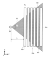
図5は、ノズル24から液相冷媒が噴霧される領域を示している。図5において、Y軸方向に沿って伝熱管群22及びノズル24から噴霧される液相冷媒の噴霧エリアMを見ている。ノズル24は、例えば、伝熱管群22においてZ軸方向に最も近い伝熱管22pから距離Lだけ離れて配置されている。また、噴霧エリアMは、中心角αをなすように形成された第一輪郭線W1及び第二輪郭線W2を有する。中心角αは特定の大きさに限定されない。中心角αは、例えば、90°以上120°以下である。 Figure 5 shows the area where the liquid-phase refrigerant is sprayed from the nozzle 24. In Figure 5, the heat transfer tube group 22 and the spray area M of the liquid-phase refrigerant sprayed from the nozzle 24 are viewed along the Y-axis direction. The nozzle 24 is disposed, for example, at a distance L from the heat transfer tube 22p that is closest in the Z-axis direction in the heat transfer tube group 22. The spray area M has a first contour line W1 and a second contour line W2 that are formed to form a central angle α. The central angle α is not limited to a specific size. The central angle α is, for example, 90° or more and 120° or less.

図6は、ノズル24から伝熱管群22に向かって噴霧された液相冷媒の噴霧及び流動の状態を示す図である。図6に示す通り、伝熱管群22は、第一段22aと、第二段22bとを含んでいる。第一段22aは、第一平面に沿って配列された複数の伝熱管22pを有する。第二段22bは、第一平面に平行な第二平面に沿って配列された複数の伝熱管22pを有し、かつ、第一平面に垂直な方向(Y軸方向)において第一段22aと隣り合っている。第一平面及び第二平面は、ZX平面に平行な平面である。 Figure 6 is a diagram showing the spray and flow state of the liquid-phase refrigerant sprayed from the nozzle 24 toward the heat transfer tube group 22. As shown in Figure 6, the heat transfer tube group 22 includes a first stage 22a and a second stage 22b. The first stage 22a has a plurality of heat transfer tubes 22p arranged along a first plane. The second stage 22b has a plurality of heat transfer tubes 22p arranged along a second plane parallel to the first plane, and is adjacent to the first stage 22a in the direction perpendicular to the first plane (Y-axis direction). The first plane and the second plane are planes parallel to the ZX plane.

図6に示す通り、例えば、第一段22aと第二段22bとの間には、第一段22aの複数の伝熱管22pの配列方向における第一段22aの一端から他端まで有体物に交差しない仮想平面が存在する。 As shown in FIG. 6, for example, between the first stage 22a and the second stage 22b, there exists an imaginary plane that does not intersect with any tangible object from one end of the first stage 22a to the other end in the arrangement direction of the multiple heat transfer tubes 22p of the first stage 22a.

図6に示す通り、例えば、第一段22aの複数の伝熱管22p及び第二段22bの複数の伝熱管22pは、伝熱管22pの長手方向(X軸方向)に垂直な第三平面において長方形格子、正方形格子、又は平行四辺形格子をなす。第三平面は、YZ平面に平行な平面である。 As shown in FIG. 6, for example, the heat transfer tubes 22p of the first stage 22a and the heat transfer tubes 22p of the second stage 22b form a rectangular lattice, a square lattice, or a parallelogram lattice in a third plane perpendicular to the longitudinal direction (X-axis direction) of the heat transfer tubes 22p. The third plane is a plane parallel to the YZ plane.

図6に示す通り、ノズル24から噴霧される液相冷媒の噴霧パターンの噴霧軸Amは、第一段22aの複数の伝熱管22pの第一端部22jと、第二段22bの複数の伝熱管22pの第二端部22kとの間を通過する。第一端部22jは、第一平面に垂直な方向(Y軸方向)において第二段22bに近い端部である。第二端部22kは、第一平面に垂直な方向(Y軸方向)において第一段22aに近い端部である。ノズル24から噴霧される液相冷媒の噴霧パターンは、第一段22aと第二段22bとの間を通過する。 As shown in FIG. 6, the spray axis Am of the spray pattern of the liquid-phase refrigerant sprayed from the nozzle 24 passes between the first end 22j of the heat transfer tubes 22p of the first stage 22a and the second end 22k of the heat transfer tubes 22p of the second stage 22b. The first end 22j is the end closer to the second stage 22b in the direction perpendicular to the first plane (Y-axis direction). The second end 22k is the end closer to the first stage 22a in the direction perpendicular to the first plane (Y-axis direction). The spray pattern of the liquid-phase refrigerant sprayed from the nozzle 24 passes between the first stage 22a and the second stage 22b.

第二段22bは、例えば、重力方向において第一段22aの下方に配置されている。伝熱管群22は、例えば、下部伝熱管群22cを含む。下部伝熱管群22cは、複数の伝熱管22pを有し、かつ、重力方向において第二段22bの下方に配置されている。下部伝熱管群22cの複数の伝熱管22pのそれぞれは、例えば、第二段22bの複数の伝熱管22pのいずれかの真下に配置されている。 The second stage 22b is, for example, disposed below the first stage 22a in the direction of gravity. The heat transfer tube group 22 includes, for example, a lower heat transfer tube group 22c. The lower heat transfer tube group 22c has a plurality of heat transfer tubes 22p and is disposed below the second stage 22b in the direction of gravity. Each of the plurality of heat transfer tubes 22p of the lower heat transfer tube group 22c is, for example, disposed directly below one of the plurality of heat transfer tubes 22p of the second stage 22b.

図6に示す通り、下部伝熱管群22cの複数の伝熱管22pは、例えば、第二段22bの複数の伝熱管22pとともに、第三平面において長方形格子又は正方形格子をなしている。 As shown in FIG. 6, the heat transfer tubes 22p of the lower heat transfer tube group 22c, together with the heat transfer tubes 22p of the second stage 22b, form a rectangular or square lattice in the third plane.

[1-2.動作]
以上のように、シェルアンドチューブ式熱交換器として構成された蒸発器101について、以下その動作、作用を説明する。
[1-2. Operation]
The operation and function of the evaporator 101 configured as a shell-and-tube heat exchanger as described above will be described below.

冷凍サイクル装置100の定常運転において、蒸発器101では、ポンプ26が作動し、液相冷媒が循環回路25及びヘッダー23を通ってノズル24に供給される。これにより、ノズル24から伝熱管群22に向かって液相冷媒が噴霧される。一方、蒸発器101の外部から二次側流入口28aを通って第一カバー29aの内部に熱媒体が導かれる。次に、熱媒体は、X軸正方向に伝熱管22pの内部を通過して第二カバー29bの内部の仕切板29dの下方の空間に導かれる。第二カバー29bの内部において熱媒体の流れの向きが反転し、熱媒体は、X軸負方向に伝熱管22pの内部を通過して第一カバー29aの内部の2つの仕切板29cの間の空間に導かれる。次に、第一カバー29aの内部において熱媒体の流れの向きが反転し、熱媒体は、X軸正方向に伝熱管22pの内部を通過して第二カバー29bの内部の仕切板29dの上方の空間に導かれる。第二カバー29bの内部において熱媒体の流れの向きが反転し、熱媒体は、X軸負方向に伝熱管22pの内部を通過して第一カバー29aの内部に導かれる。その後、熱媒体は、二次側流出口28bを通って、蒸発器101の外部に導かれる。 During steady operation of the refrigeration cycle device 100, the pump 26 in the evaporator 101 operates, and liquid-phase refrigerant is supplied to the nozzle 24 through the circulation circuit 25 and the header 23. As a result, the liquid-phase refrigerant is sprayed from the nozzle 24 toward the heat transfer tube group 22. Meanwhile, the heat medium is guided from the outside of the evaporator 101 through the secondary side inlet 28a to the inside of the first cover 29a. Next, the heat medium passes through the inside of the heat transfer tube 22p in the positive direction of the X-axis and is guided to the space below the partition plate 29d inside the second cover 29b. Inside the second cover 29b, the flow direction of the heat medium is reversed, and the heat medium passes through the inside of the heat transfer tube 22p in the negative direction of the X-axis and is guided to the space between the two partition plates 29c inside the first cover 29a. Next, the flow direction of the heat medium is reversed inside the first cover 29a, and the heat medium passes through the inside of the heat transfer tube 22p in the positive direction of the X axis and is guided to the space above the partition plate 29d inside the second cover 29b. The flow direction of the heat medium is reversed inside the second cover 29b, and the heat medium passes through the inside of the heat transfer tube 22p in the negative direction of the X axis and is guided to the inside of the first cover 29a. The heat medium then passes through the secondary side outlet 28b and is guided to the outside of the evaporator 101.

図4に示す通り、ノズル24は、Y軸方向において隣り合った2つの段の伝熱管の間の空間に向かって液相冷媒を噴霧する。液相冷媒は、2つの段の間で噴霧軸Amが延びる噴霧パターンで噴霧される。液相冷媒の噴霧により生じた霧状の液相冷媒は、伝熱管22pの外面に付着する。伝熱管22pの内部の熱媒体と伝熱管22pの外面に付着した液相冷媒との間の熱交換により、液相冷媒が蒸発して気相冷媒が生成される。蒸発しなかった液相冷媒は、伝熱管22pの外面に沿って流動し、下方の伝熱管22pに向かって滴下される。 As shown in FIG. 4, the nozzle 24 sprays liquid-phase refrigerant toward the space between two adjacent stages of heat transfer tubes in the Y-axis direction. The liquid-phase refrigerant is sprayed in a spray pattern in which the spray axis Am extends between the two stages. The mist of liquid-phase refrigerant produced by the spraying of the liquid-phase refrigerant adheres to the outer surface of the heat transfer tube 22p. The liquid-phase refrigerant evaporates to generate gas-phase refrigerant due to heat exchange between the heat medium inside the heat transfer tube 22p and the liquid-phase refrigerant adhering to the outer surface of the heat transfer tube 22p. The liquid-phase refrigerant that does not evaporate flows along the outer surface of the heat transfer tube 22p and drips toward the lower heat transfer tube 22p.

図5に示す通り、例えば、第一平面に垂直な方向(Y軸方向)から第一段22aを見たときに、第一段22aの伝熱管22pの中心軸Axに垂直に噴霧軸Amが延びるように、液相冷媒の噴霧パターンが形成される。伝熱管群22においてZ軸方向においてノズル24に最も近い伝熱管22pとノズル24との間の距離Lが所定の大きさを有する。このため、第一段22aにおける最前列の伝熱管22pから最後列の伝熱管22pに向かって液相冷媒の噴霧エリアMが徐々に拡大し、第一段22aの最後列の伝熱管22pの外面の十分な範囲が液相冷媒で濡れる。 As shown in FIG. 5, for example, when the first stage 22a is viewed from a direction perpendicular to the first plane (Y-axis direction), the spray pattern of the liquid-phase refrigerant is formed so that the spray axis Am extends perpendicular to the central axis Ax of the heat transfer tube 22p of the first stage 22a. In the heat transfer tube group 22, the distance L between the nozzle 24 and the heat transfer tube 22p closest to the nozzle 24 in the Z-axis direction has a predetermined size. Therefore, the spray area M of the liquid-phase refrigerant gradually expands from the front row of heat transfer tubes 22p to the last row of heat transfer tubes 22p in the first stage 22a, and a sufficient area of the outer surface of the last row of heat transfer tubes 22p of the first stage 22a is wetted with the liquid-phase refrigerant.

図6に示す通り、ノズル24から噴霧された液相冷媒は、第三平面において長方形格子、正方形格子、又は平行四辺形格子をなすように配置された第一段22a及び第二段22bにおける伝熱管22p同士の間を通過する。第一段22aと第二段22bとの間には、ノズル24から噴霧された液相冷媒の進行を直接妨げる伝熱管等の部材は存在しない。このため、第一段22aと第二段22bとの間においてノズル24から噴霧された液相冷媒が直進しやすい。一方、ノズル24から噴霧された液相冷媒の一部は、第一段22aの伝熱管22pの第一端部22j及び第二段22bの伝熱管22pの第二端部22kに接触する。第一段22aの伝熱管22pに接触した液相冷媒の一部は、液相冷媒の流れに対する伝熱管22pの前縁に沿ってY軸正方向に流動する。一方、第二段22bの伝熱管22pに接触した液相冷媒の一部は、伝熱管22pの前縁に沿ってY軸負方向に流動する。加えて、液相冷媒の別の一部は、第二段22bの伝熱管22pの後縁に沿ってY軸負方向に流動する。このような液相冷媒の流動が第一段22a及び第二段22bの各列の伝熱管22pの周囲で生じる。 As shown in FIG. 6, the liquid-phase refrigerant sprayed from the nozzle 24 passes between the heat transfer tubes 22p in the first stage 22a and the second stage 22b arranged to form a rectangular lattice, a square lattice, or a parallelogram lattice in the third plane. Between the first stage 22a and the second stage 22b, there are no components such as heat transfer tubes that directly impede the progress of the liquid-phase refrigerant sprayed from the nozzle 24. Therefore, the liquid-phase refrigerant sprayed from the nozzle 24 tends to move straight between the first stage 22a and the second stage 22b. On the other hand, a part of the liquid-phase refrigerant sprayed from the nozzle 24 contacts the first end 22j of the heat transfer tube 22p of the first stage 22a and the second end 22k of the heat transfer tube 22p of the second stage 22b. A part of the liquid-phase refrigerant that contacts the heat transfer tube 22p of the first stage 22a flows in the positive Y-axis direction along the front edge of the heat transfer tube 22p relative to the flow of the liquid-phase refrigerant. On the other hand, a portion of the liquid-phase refrigerant in contact with the heat transfer tubes 22p of the second stage 22b flows in the negative Y-axis direction along the leading edge of the heat transfer tubes 22p. In addition, another portion of the liquid-phase refrigerant flows in the negative Y-axis direction along the trailing edge of the heat transfer tubes 22p of the second stage 22b. Such a flow of the liquid-phase refrigerant occurs around the heat transfer tubes 22p of each row of the first stage 22a and the second stage 22b.

図6に示す通り、第一段22a及び第二段22bからなる上部伝熱管群22mにおいて、液相冷媒が伝熱管22pの外面に直接接触して強制対流を伴う熱伝達が生じ、液相冷媒と熱媒体との間の熱交換が促進される。 As shown in FIG. 6, in the upper heat transfer tube group 22m consisting of the first stage 22a and the second stage 22b, the liquid phase refrigerant comes into direct contact with the outer surface of the heat transfer tube 22p, and heat transfer occurs accompanied by forced convection, promoting heat exchange between the liquid phase refrigerant and the heat medium.

第二段22bの伝熱管22pの外面において液相冷媒はY軸負方向に流動しながら液膜を形成し、液膜をなす液相冷媒の一部が蒸発する。上部伝熱管群22mにおいて蒸発しきれなかった未蒸発の液相冷媒は、第二段22bの伝熱管22pの最下部から下部伝熱管群22cの伝熱管22pに向かって滴下される。滴下された液相冷媒は、伝熱管22pの外面で液膜を形成しながら下方に流動し、一部の液相冷媒は蒸発し、別の一部の液相冷媒はさらに下方の伝熱管22pに向かって滴下される。このような液相冷媒の流動及び滴下が下部伝熱管群22cの各列の伝熱管22pの周囲で生じる。このように、下部伝熱管群22cの伝熱管22pの周囲には、ノズル24から噴霧された液相冷媒が上部伝熱管群22mの伝熱管22pから滴下されて間接的に供給される。滴下後に残った液相冷媒は、シェル21の底部に貯留される。 The liquid-phase refrigerant forms a liquid film on the outer surface of the heat transfer tube 22p of the second stage 22b while flowing in the negative Y-axis direction, and a part of the liquid-phase refrigerant forming the liquid film evaporates. The unevaporated liquid-phase refrigerant that has not been completely evaporated in the upper heat transfer tube group 22m is dripped from the bottom of the heat transfer tube 22p of the second stage 22b toward the heat transfer tube 22p of the lower heat transfer tube group 22c. The dripped liquid-phase refrigerant flows downward while forming a liquid film on the outer surface of the heat transfer tube 22p, and some of the liquid-phase refrigerant evaporates, and another part of the liquid-phase refrigerant is dripped toward the heat transfer tube 22p further below. Such flow and dripping of the liquid-phase refrigerant occurs around the heat transfer tube 22p of each row of the lower heat transfer tube group 22c. In this way, the liquid-phase refrigerant sprayed from the nozzle 24 is dripped from the heat transfer tube 22p of the upper heat transfer tube group 22m and indirectly supplied to the periphery of the heat transfer tube 22p of the lower heat transfer tube group 22c. The liquid refrigerant remaining after dripping is stored at the bottom of the shell 21.

上部伝熱管群22mの伝熱管22pの周囲には、ノズル24から噴霧された液相冷媒が直接供給されて強制対流が生じる。ノズル24は、噴霧軸Amを有する扁平な噴霧パターンで液相冷媒を噴霧するので、液相冷媒が第一段22aと第二段22bとの間で直進しやすい。これにより、上部伝熱管群22mにおいて、ノズル24に対して遠方の伝熱管22pの周囲でも液相冷媒の強制対流が生じやすい。このため、ノズル24に対して遠方の伝熱管22pの外面が液相冷媒で濡れやすく、遠方の伝熱管22pの外面においてドライアウトが発生しにくい。 Liquid-phase refrigerant sprayed from the nozzle 24 is directly supplied around the heat transfer tubes 22p of the upper heat transfer tube group 22m, causing forced convection. The nozzle 24 sprays the liquid-phase refrigerant in a flat spray pattern having a spray axis Am, so the liquid-phase refrigerant tends to move straight between the first stage 22a and the second stage 22b. This makes it easy for forced convection of the liquid-phase refrigerant to occur around the heat transfer tubes 22p that are far from the nozzle 24 in the upper heat transfer tube group 22m. Therefore, the outer surface of the heat transfer tubes 22p far from the nozzle 24 is easily wetted with the liquid-phase refrigerant, and dryout is less likely to occur on the outer surface of the far heat transfer tubes 22p.

加えて、上部伝熱管群22mの伝熱管22pから下部伝熱管群22cに向かって液相冷媒の滴下が生じるので、下部伝熱管群22cにおいて、ノズル24に対して遠方の伝熱管22pの外面でも液相冷媒の液膜が形成されやすい。このため、ノズル24に対して遠方に位置する伝熱管22pの外面が液相冷媒で濡れやすく、遠方の伝熱管22pの外面においてドライアウトが発生しにくい。 In addition, liquid-phase refrigerant drips from the heat transfer tubes 22p of the upper heat transfer tube group 22m toward the lower heat transfer tube group 22c, so that in the lower heat transfer tube group 22c, a liquid film of liquid-phase refrigerant is likely to form on the outer surface of the heat transfer tubes 22p that are far from the nozzle 24. Therefore, the outer surface of the heat transfer tubes 22p located far from the nozzle 24 is likely to become wet with the liquid-phase refrigerant, and dryout is unlikely to occur on the outer surface of the distant heat transfer tubes 22p.

[1-3.効果等]
以上のように、本実施形態において、シェルアンドチューブ式熱交換器として構成された蒸発器101は、シェル21と、伝熱管群22と、ノズル24とを備えている。伝熱管群22は、シェル21の内部に配置されている。ノズル24は、伝熱管群22に向かって液相冷媒を噴霧する。伝熱管群22は、第一段22aと、第二段22bとを含んでいる。第一段22aは、第一平面に沿って配列された複数の伝熱管22pを有する。第二段22bは、第一平面に平行な第二平面に沿って配列された複数の伝熱管22pを有し、かつ、第一平面に垂直な方向において第一段22aと隣り合っている。ノズル24は、噴霧軸Amを有し、かつ、第一段22aと第二段22bとの間を通過する扁平な噴霧パターンで液相冷媒を噴霧する。噴霧軸Amは、第一段22aの複数の伝熱管22pの第一端部22jと、第二段22bの複数の伝熱管22pの第二端部22kとの間を通過する。第一端部22jは、第一平面に垂直な方向において第一段22aの複数の伝熱管22pの第二段22bに近い端部である。第二端部22kは、第一平面に垂直な方向において第二段22bの複数の伝熱管22pの第一段22aに近い端部である。
[1-3. Effects, etc.]
As described above, in this embodiment, the evaporator 101 configured as a shell-and-tube heat exchanger includes the shell 21, the heat transfer tube group 22, and the nozzle 24. The heat transfer tube group 22 is disposed inside the shell 21. The nozzle 24 sprays a liquid-phase refrigerant toward the heat transfer tube group 22. The heat transfer tube group 22 includes a first stage 22a and a second stage 22b. The first stage 22a has a plurality of heat transfer tubes 22p arranged along a first plane. The second stage 22b has a plurality of heat transfer tubes 22p arranged along a second plane parallel to the first plane, and is adjacent to the first stage 22a in a direction perpendicular to the first plane. The nozzle 24 has a spray axis Am, and sprays the liquid-phase refrigerant in a flat spray pattern passing between the first stage 22a and the second stage 22b. The spray axis Am passes between the first ends 22j of the heat transfer tubes 22p of the first stage 22a and the second ends 22k of the heat transfer tubes 22p of the second stage 22b. The first ends 22j are ends of the heat transfer tubes 22p of the first stage 22a that are closer to the second stage 22b in a direction perpendicular to the first plane. The second ends 22k are ends of the heat transfer tubes 22p of the second stage 22b that are closer to the first stage 22a in a direction perpendicular to the first plane.

これにより、ノズル24は、噴霧軸Amを有する扁平な噴霧パターンで液相冷媒を噴霧するので、液相冷媒が第一段22aと第二段22bとの間で直進しやすい。このため、第一段22a及び第二段22bにおいて、ノズル24に対して遠方の伝熱管22pの周囲でも液相冷媒の強制対流が生じやすい。その結果、ノズル24に対して遠方の伝熱管22pの外面が液相冷媒で濡れやすく、遠方の伝熱管22pの外面においてドライアウトが発生しにくい。 As a result, the nozzle 24 sprays the liquid-phase refrigerant in a flat spray pattern having the spray axis Am, so that the liquid-phase refrigerant tends to move in a straight line between the first stage 22a and the second stage 22b. Therefore, in the first stage 22a and the second stage 22b, forced convection of the liquid-phase refrigerant tends to occur around the heat transfer tube 22p that is far from the nozzle 24. As a result, the outer surface of the heat transfer tube 22p that is far from the nozzle 24 tends to be wetted with the liquid-phase refrigerant, and dryout is less likely to occur on the outer surface of the far heat transfer tube 22p.

本実施形態のように、第一段22aと第二段22bとの間には、第一段22aの複数の伝熱管22pの配列方向における第一段22aの一端から他端まで有体物に交差しない仮想平面が存在していてもよい。これにより、第一段22aと第二段22bとの間において、第一段22aの一端から他端まで液相冷媒が直進しやすく、遠方の伝熱管22pの外面においてより確実にドライアウトが発生しにくい。 As in this embodiment, between the first stage 22a and the second stage 22b, there may be an imaginary plane that does not intersect with any tangible object from one end of the first stage 22a to the other end in the arrangement direction of the heat transfer tubes 22p of the first stage 22a. This makes it easier for the liquid phase refrigerant to flow straight from one end of the first stage 22a to the other end between the first stage 22a and the second stage 22b, and makes it more difficult for dryout to occur on the outer surface of the distant heat transfer tube 22p.

本実施形態のように、第一段22aの複数の伝熱管22p及び第二段22bの複数の伝熱管22pは、伝熱管22pの長手方向に垂直な第三平面において、長方形格子、正方形格子、又は平行四辺形格子をなしていてもよい。これにより、第一段22aと第二段22bとの間における液相冷媒の流れが安定しやすく直進しやすい。その結果、遠方の伝熱管22pの外面においてより確実にドライアウトが発生しにくい。 As in this embodiment, the multiple heat transfer tubes 22p of the first stage 22a and the multiple heat transfer tubes 22p of the second stage 22b may form a rectangular lattice, a square lattice, or a parallelogram lattice in a third plane perpendicular to the longitudinal direction of the heat transfer tubes 22p. This makes it easier for the flow of liquid-phase refrigerant between the first stage 22a and the second stage 22b to be stable and to move in a straight line. As a result, dryout is more unlikely to occur on the outer surface of the distant heat transfer tube 22p.

本実施形態のように、第二段22bは、重力方向において第一段22aの下方に配置されていてもよい。加えて、伝熱管群22は、複数の伝熱管22pを有し、かつ、重力方向において第二段22bの下方に配置されている下部伝熱管群22cを含んでいてもよい。これにより、第二段22bから下部伝熱管群22cに向かって液相冷媒の滴下が生じ、下部伝熱管群22cにおいてノズル24に対して遠方の伝熱管22pの外面も液相冷媒で濡れやすい。その結果、下部伝熱管群22cの遠方の伝熱管22pの外面においてドライアウトが発生しにくい。この場合、第一段22aの複数の伝熱管22p及び第二段22bの複数の伝熱管22pは、伝熱管22pの長手方向に垂直な第三平面において、長方形格子又は正方形格子をなしていてもよい。これにより、下部伝熱管群22cに向かってより確実に液相冷媒の滴下が生じやすい。 As in this embodiment, the second stage 22b may be disposed below the first stage 22a in the direction of gravity. In addition, the heat transfer tube group 22 may include a lower heat transfer tube group 22c having a plurality of heat transfer tubes 22p and disposed below the second stage 22b in the direction of gravity. As a result, the liquid phase refrigerant drips from the second stage 22b toward the lower heat transfer tube group 22c, and the outer surface of the heat transfer tube 22p far from the nozzle 24 in the lower heat transfer tube group 22c is also likely to be wetted with the liquid phase refrigerant. As a result, dryout is unlikely to occur on the outer surface of the heat transfer tube 22p far from the lower heat transfer tube group 22c. In this case, the plurality of heat transfer tubes 22p of the first stage 22a and the plurality of heat transfer tubes 22p of the second stage 22b may form a rectangular lattice or a square lattice on a third plane perpendicular to the longitudinal direction of the heat transfer tube 22p. As a result, the liquid phase refrigerant is more likely to drip toward the lower heat transfer tube group 22c.

本実施形態のように、下部伝熱管群22cの複数の伝熱管22pは、第二段22bの複数の伝熱管22pとともに、第三平面において長方形格子又は正方形格子をなしている。これにより、第二段22bの複数の伝熱管22pから滴下された液相冷媒が下部伝熱管群22cの各伝熱管22pの外面においてより確実に液膜を形成してその外面を濡らしやすい。その結果、下部伝熱管群22cの遠方の伝熱管22pの外面においてより確実にドライアウトが発生しにくい。 As in this embodiment, the multiple heat transfer tubes 22p of the lower heat transfer tube group 22c, together with the multiple heat transfer tubes 22p of the second stage 22b, form a rectangular lattice or a square lattice in the third plane. This makes it easier for the liquid phase refrigerant dripping from the multiple heat transfer tubes 22p of the second stage 22b to more reliably form a liquid film on the outer surface of each heat transfer tube 22p of the lower heat transfer tube group 22c and wet the outer surface. As a result, it is more reliably less likely that dryout will occur on the outer surface of the heat transfer tubes 22p at the far end of the lower heat transfer tube group 22c.

本実施形態のように、シェルアンドチューブ式熱交換器として構成された蒸発器101を備えた、冷凍サイクル装置100を提供できる。ノズル24に対して遠方の伝熱管22pの外面においてドライアウトが発生しにくいので、冷凍サイクル装置100が高い成績係数(COP)を発揮しやすい。 As in this embodiment, a refrigeration cycle device 100 can be provided that includes an evaporator 101 configured as a shell-and-tube heat exchanger. Since dry-out is unlikely to occur on the outer surface of the heat transfer tube 22p that is far from the nozzle 24, the refrigeration cycle device 100 is likely to achieve a high coefficient of performance (COP).

本実施形態によれば、下記の事項(I)及び(II)を含む熱交換方法を提供できる。
(I)第一段22aと、第二段22bとを含む伝熱管群22の内部において熱媒体を通過させる。第一段22aは、第一平面に沿って配列された複数の伝熱管を有する。第二段22bは、第一平面に平行な第二平面に沿って配列された複数の伝熱管22pを有し、かつ、第一平面に垂直な方向において第一段22aと隣り合っている。
(II)噴霧軸Amを有し、かつ、第一段22aと第二段22bとの間を通過する扁平な噴霧パターンで伝熱管群22に向かって液相冷媒を噴霧し、熱媒体と液相冷媒とを熱交換させる。噴霧軸Amは、第一段22aの複数の伝熱管22pの第二段22bに近い第一端部22jと、第二段22bの複数の伝熱管22pの第一段22aに近い第二端部22kとの間を通過する。
According to this embodiment, a heat exchange method including the following items (I) and (II) can be provided.
(I) A heat medium is passed through a heat transfer tube group 22 including a first stage 22a and a second stage 22b. The first stage 22a has a plurality of heat transfer tubes arranged along a first plane. The second stage 22b has a plurality of heat transfer tubes 22p arranged along a second plane parallel to the first plane, and is adjacent to the first stage 22a in a direction perpendicular to the first plane.
(II) The liquid-phase refrigerant is sprayed toward the heat transfer tube group 22 in a flat spray pattern having a spray axis Am and passing between the first stage 22a and the second stage 22b, thereby exchanging heat between the heat medium and the liquid-phase refrigerant. The spray axis Am passes between a first end 22j of the plurality of heat transfer tubes 22p of the first stage 22a, which is close to the second stage 22b, and a second end 22k of the plurality of heat transfer tubes 22p of the second stage 22b, which is close to the first stage 22a.

(実施の形態2)
以下、図7を用いて、実施の形態2を説明する。実施の形態2は、特に説明する部分を除き、実施の形態1と同様に構成されている。実施の形態1の構成要素と同一又は対応する実施の形態2の構成要素には同一の符号を付し、詳細な説明を省略する。実施の形態1に関する説明は、技術的に矛盾しない限り、実施の形態2にもあてはまる。
(Embodiment 2)
Hereinafter, the second embodiment will be described with reference to FIG. 7. The second embodiment is configured similarly to the first embodiment, except for the parts that will be particularly described. The components of the second embodiment that are the same as or correspond to those of the first embodiment are given the same reference numerals, and detailed description will be omitted. The description of the first embodiment also applies to the second embodiment, unless there is a technical contradiction.

[2-1.構成]
図7は、実施の形態2において、ノズル24から液相冷媒が噴霧される領域を示している。図7において、Y軸方向に沿って伝熱管群22及びノズル24から噴霧される液相冷媒の噴霧エリアMを見ている。図7に示す通り、第一平面に垂直な方向(Y軸方向)に沿って第一段22aを見たときに、ノズル24から噴霧される液相冷媒の噴霧パターンの噴霧軸Amは、直線Pに対して所定の大きさの鋭角θをなす。直線Pは、第一段22aの伝熱管22pの長手方向(X軸方向)に垂直に延びている。
[2-1. Configuration]
Fig. 7 shows an area where liquid-phase refrigerant is sprayed from the nozzle 24 in the second embodiment. In Fig. 7, the heat transfer tube group 22 and the spray area M of the liquid-phase refrigerant sprayed from the nozzle 24 are viewed along the Y-axis direction. As shown in Fig. 7, when the first stage 22a is viewed along a direction perpendicular to the first plane (Y-axis direction), the spray axis Am of the spray pattern of the liquid-phase refrigerant sprayed from the nozzle 24 forms an acute angle θ of a predetermined magnitude with respect to the straight line P. The straight line P extends perpendicular to the longitudinal direction (X-axis direction) of the heat transfer tube 22p of the first stage 22a.

鋭角θは特定の値に限定されない。鋭角θは、例えば、α/2である。αは、噴霧エリアMの中心角である。例えば、中心角αが80°であり、鋭角θが40°である。 The acute angle θ is not limited to a specific value. For example, the acute angle θ is α/2. α is the central angle of the spray area M. For example, the central angle α is 80°, and the acute angle θ is 40°.

[2-2.動作]
以上のように構成された実施の形態2について、以下その動作、作用を説明する。
[2-2. Operation]
The operation and function of the second embodiment configured as above will be described below.

図7に示す通り、噴霧軸Amが直線Pに対して鋭角θをなすようにノズル24から液相冷媒が噴霧される。ノズル24が伝熱管群22の近くに配置された場合でも、XZ平面において噴霧エリアMと重なる伝熱管群22の範囲が大きくなりやすい。例えば、噴霧エリアMの第一輪郭線W1が直線Pに沿って延び、噴霧エリアMの第二輪郭線W2が伝熱管22pの中心軸Axに沿って延びやすい。 As shown in FIG. 7, liquid-phase refrigerant is sprayed from the nozzle 24 so that the spray axis Am forms an acute angle θ with the line P. Even if the nozzle 24 is positioned close to the heat transfer tube group 22, the area of the heat transfer tube group 22 that overlaps with the spray area M in the XZ plane tends to be large. For example, the first contour line W1 of the spray area M tends to extend along the line P, and the second contour line W2 of the spray area M tends to extend along the central axis Ax of the heat transfer tube 22p.

噴霧軸Amが直線Pと平行になるようにノズル24が配置されている場合、換言すると、噴霧軸Amが伝熱管22pの中心軸Axに垂直になるようにノズル24が配置されている場合を考える。この場合、距離Lが小さく、ノズル24が伝熱管群22の近くに配置されていると、XZ平面において、伝熱管群22のノズル24に近い伝熱管22pと噴霧エリアMとが重なる範囲が小さくなる。特に、伝熱管22pの長手方向においてノズル24から離れた部分が噴霧エリアMと重なりにくい。これにより、伝熱管群22の伝熱管22pの外面において、ノズル24から噴霧された液相冷媒が到達しにくい部分が生じやすい。一方、本実施形態によれば、このような状態が発生することを抑制できる。このため、伝熱管群22の伝熱管22pの外面の広い範囲を液相冷媒で濡らすことができ、伝熱管22pの外面においてドライアウトが発生しにくい。 Consider the case where the nozzle 24 is arranged so that the spray axis Am is parallel to the straight line P, in other words, the nozzle 24 is arranged so that the spray axis Am is perpendicular to the central axis Ax of the heat transfer tube 22p. In this case, if the distance L is small and the nozzle 24 is arranged close to the heat transfer tube group 22, the overlapping range of the heat transfer tube 22p close to the nozzle 24 of the heat transfer tube group 22 and the spray area M becomes small in the XZ plane. In particular, the portion of the heat transfer tube 22p far from the nozzle 24 in the longitudinal direction is unlikely to overlap with the spray area M. As a result, it is easy for the liquid phase refrigerant sprayed from the nozzle 24 to reach the outer surface of the heat transfer tube 22p of the heat transfer tube group 22 to reach a portion. On the other hand, according to the present embodiment, it is possible to suppress the occurrence of such a state. Therefore, a wide range of the outer surface of the heat transfer tube 22p of the heat transfer tube group 22 can be wetted with the liquid phase refrigerant, and dryout is unlikely to occur on the outer surface of the heat transfer tube 22p.

図7に示す通り、噴霧軸Amが直線Pに対して鋭角θをなすように液相冷媒が噴霧されると、ノズル24から噴霧された液相冷媒は流れC1及び流れC2を生じさせる。流れC1は、第一段22a及び第二段22bにおける伝熱管22p同士の間を通過する液相冷媒の流れである。流れC2は、伝熱管22pの外面の前縁に衝突して伝熱管22pの長手方向(X軸方向)に沿って移動する液相冷媒の流れである。ノズル24から噴霧された液相冷媒の一部は、X軸方向の速度成分を有している状態で伝熱管22pの外面の前縁に衝突するので、このような液相冷媒の流れが生じる。 As shown in FIG. 7, when the liquid-phase refrigerant is sprayed so that the spray axis Am forms an acute angle θ with respect to the line P, the liquid-phase refrigerant sprayed from the nozzle 24 generates flows C1 and C2. Flow C1 is the flow of liquid-phase refrigerant passing between the heat transfer tubes 22p in the first stage 22a and the second stage 22b. Flow C2 is the flow of liquid-phase refrigerant that collides with the leading edge of the outer surface of the heat transfer tube 22p and moves along the longitudinal direction (X-axis direction) of the heat transfer tube 22p. A portion of the liquid-phase refrigerant sprayed from the nozzle 24 collides with the leading edge of the outer surface of the heat transfer tube 22p while having a velocity component in the X-axis direction, and thus such a flow of liquid-phase refrigerant is generated.

流れC1は、ノズル24から噴霧された中心角αの噴霧エリアMをなすように広がる液相冷媒の流れである。この流れC1における液相冷媒は、第一段22aの複数の伝熱管22pの第一端部22j又は第二段22bの複数の伝熱管22pの第二端部22kに接触しながら、第一段22aと第二段22bとの間を通過する。 Flow C1 is a flow of liquid-phase refrigerant that spreads to form a spray area M with a central angle α sprayed from the nozzle 24. The liquid-phase refrigerant in this flow C1 passes between the first stage 22a and the second stage 22b while contacting the first ends 22j of the heat transfer tubes 22p of the first stage 22a or the second ends 22k of the heat transfer tubes 22p of the second stage 22b.

流れC1及び流れC2の発生により、第一段22aにおける複数の伝熱管22pの配列方向(Z軸方向)への液相冷媒の移動に加え、伝熱管22pの長手方向(X軸方向)への液相冷媒の移動も生じる。このため、強制対流を伴う熱伝達が促進される。加えて、上記の通り、ノズル24に近い伝熱管22pを含む、伝熱管群22の伝熱管22pの外面の広い範囲が液相冷媒で濡れる。 The generation of flows C1 and C2 causes the liquid-phase refrigerant to move in the arrangement direction (Z-axis direction) of the heat transfer tubes 22p in the first stage 22a, as well as in the longitudinal direction (X-axis direction) of the heat transfer tubes 22p. This promotes heat transfer accompanied by forced convection. In addition, as described above, a wide area of the outer surface of the heat transfer tubes 22p of the heat transfer tube group 22, including the heat transfer tubes 22p close to the nozzle 24, becomes wet with the liquid-phase refrigerant.

[2-3.効果等]
以上のように、本実施の形態においては、第一平面に垂直な方向(Y軸方向)に沿って第一段22aを見たときに、噴霧軸Amは、直線Pに対して所定の大きさの鋭角θをなす。
[2-3. Effects, etc.]
As described above, in this embodiment, when the first stage 22a is viewed along the direction perpendicular to the first plane (the Y-axis direction), the spray axis Am forms an acute angle θ of a predetermined magnitude with respect to the straight line P.

これにより、ノズル24が伝熱管群22の近くに配置されていても、伝熱管群22の伝熱管22pの外面の広い範囲を液相冷媒で濡らすことができ、伝熱管22pの外面においてドライアウトが発生しにくい。 As a result, even if the nozzle 24 is positioned close to the heat transfer tube group 22, a wide area of the outer surface of the heat transfer tube 22p of the heat transfer tube group 22 can be wetted with liquid phase refrigerant, making it difficult for dryout to occur on the outer surface of the heat transfer tube 22p.

例えば、冷凍サイクル装置100の軽負荷条件での運転に対応させるために、ノズル24への液相冷媒の供給圧力を低下させることが考えられる。この場合、ノズル24から噴霧される液相冷媒の噴霧パターンにおける中心角が小さくなり、噴霧エリアMが狭くなりうる。また、ノズル24から噴霧される液相冷媒の流量が低下しうる。しかし、本実施形態によれば、このような場合であっても、伝熱管群22の伝熱管22pの外面の所望の範囲を液相冷媒で濡らすことができ、伝熱管22pの外面においてドライアウトが発生しにくい。 For example, in order to accommodate operation of the refrigeration cycle device 100 under light load conditions, it is possible to reduce the supply pressure of the liquid-phase refrigerant to the nozzle 24. In this case, the central angle in the spray pattern of the liquid-phase refrigerant sprayed from the nozzle 24 may become smaller, and the spray area M may become narrower. In addition, the flow rate of the liquid-phase refrigerant sprayed from the nozzle 24 may decrease. However, according to this embodiment, even in such a case, the desired range of the outer surface of the heat transfer tube 22p of the heat transfer tube group 22 can be wetted with the liquid-phase refrigerant, and dryout is less likely to occur on the outer surface of the heat transfer tube 22p.

(実施の形態3)
以下、図8を用いて、実施の形態3を説明する。実施の形態3は、特に説明する部分を除き、実施の形態1と同様に構成されている。実施の形態1の構成要素と同一又は対応する実施の形態3の構成要素には同一の符号を付し、詳細な説明を省略する。実施の形態1に関する説明は、技術的に矛盾しない限り、実施の形態3にもあてはまる。
(Embodiment 3)
Hereinafter, the third embodiment will be described with reference to FIG. 8. The third embodiment is configured similarly to the first embodiment except for the parts that will be particularly described. The same reference numerals are used to designate the same or corresponding components of the first embodiment, and detailed description will be omitted. The description of the first embodiment also applies to the third embodiment, unless there is a technical contradiction.

[3-1.構成]
図8は、実施の形態3に係る蒸発器101における液相冷媒の噴霧及び流動の状態を示す。図8に示す通り、伝熱管群22は、遠位伝熱管22dを有する。遠位伝熱管22dは、噴霧軸Amと交差する位置に配置されている。例えば、遠位伝熱管22dは、ノズル24の中心軸と交差している。第一段22aは、第一段22aの複数の伝熱管22pの配列方向(Z軸方向)において、ノズル24と遠位伝熱管22dとの間に配置されている。
[3-1. Configuration]
Fig. 8 shows the spray and flow state of the liquid-phase refrigerant in the evaporator 101 according to the third embodiment. As shown in Fig. 8, the heat transfer tube group 22 has a distal heat transfer tube 22d. The distal heat transfer tube 22d is disposed at a position intersecting with the spray axis Am. For example, the distal heat transfer tube 22d intersects with the central axis of the nozzle 24. The first stage 22a is disposed between the nozzle 24 and the distal heat transfer tube 22d in the arrangement direction (Z-axis direction) of the multiple heat transfer tubes 22p of the first stage 22a.

図8に示す通り、伝熱管群22は、例えば下部伝熱管22eを有する。下部伝熱管22eは、重力方向において遠位伝熱管22dの真下に配置されている。 As shown in FIG. 8, the heat transfer tube group 22 includes, for example, a lower heat transfer tube 22e. The lower heat transfer tube 22e is disposed directly below the distal heat transfer tube 22d in the direction of gravity.

遠位伝熱管22d及び下部伝熱管22eは、例えば、第一段22a、第二段22b、又は下部伝熱管群22cにおける伝熱管22pと同様の形状及び寸法を有している。 The distal heat transfer tube 22d and the lower heat transfer tube 22e have, for example, the same shape and dimensions as the heat transfer tube 22p in the first stage 22a, the second stage 22b, or the lower heat transfer tube group 22c.

[3-2.動作]
以上のように構成された実施の形態3について、以下その動作、作用を説明する。
[3-2. Operation]
The operation and function of the third embodiment configured as above will be described below.

第一段22aと第二段22bとの間を通過した液相冷媒は、遠位伝熱管22dに衝突して捕捉される。このため、遠位伝熱管22dの周囲における強制対流に伴う熱伝達は、第一段22a及び第二段22bにおける伝熱管22pの周囲における強制対流に伴う熱伝達に比べて、大幅に促進される。加えて、ノズル24に対して遠方に位置する遠位伝熱管22dの外面を液相冷媒で濡らすことができ、ノズル24に対して遠方の伝熱管の外面においてドライアウトを抑制できる。 The liquid-phase refrigerant that passes between the first stage 22a and the second stage 22b collides with the distal heat transfer tube 22d and is captured. Therefore, the heat transfer caused by the forced convection around the distal heat transfer tube 22d is significantly promoted compared to the heat transfer caused by the forced convection around the heat transfer tube 22p in the first stage 22a and the second stage 22b. In addition, the outer surface of the distal heat transfer tube 22d located far from the nozzle 24 can be wetted with the liquid-phase refrigerant, and dryout can be suppressed on the outer surface of the heat transfer tube far from the nozzle 24.

遠位伝熱管22dに衝突した液相冷媒は、遠位伝熱管22dの外面に沿って流動し、下部伝熱管22eに向かって滴下される。これにより、ノズル24に対して遠方に位置する下部伝熱管22eの外面を液相冷媒で濡らすことができ、ノズル24に対して遠方の伝熱管の外面においてドライアウトを抑制できる。 The liquid refrigerant that collides with the distal heat transfer tube 22d flows along the outer surface of the distal heat transfer tube 22d and drips toward the lower heat transfer tube 22e. This allows the outer surface of the lower heat transfer tube 22e, which is located far from the nozzle 24, to be wetted with the liquid refrigerant, thereby preventing dryout on the outer surface of the heat transfer tube far from the nozzle 24.

[3-3.効果等]
以上のように、本実施の形態においては、伝熱管群22は、遠位伝熱管22dを有し、遠位伝熱管22dが噴霧軸Amと交差する位置に配置されている。加えて、第一段22aは、第一段22aの複数の伝熱管22pの配列方向において、ノズル24と遠位伝熱管22dとの間に配置されている。
[3-3. Effects, etc.]
As described above, in the present embodiment, the heat transfer tube group 22 has the distal heat transfer tube 22d, and the distal heat transfer tube 22d is disposed at a position intersecting the spray axis Am. In addition, the first stage 22a is disposed between the nozzle 24 and the distal heat transfer tube 22d in the arrangement direction of the heat transfer tubes 22p of the first stage 22a.

これにより、遠位伝熱管22dの周囲における強制対流に伴う熱伝達が大幅に促進されるとともに、ノズル24に対して遠方に位置する遠位伝熱管22dの外面においてドライアウトを抑制できる。 This significantly promotes heat transfer associated with forced convection around the distal heat transfer tube 22d, and also suppresses dry-out on the outer surface of the distal heat transfer tube 22d, which is located far from the nozzle 24.

例えば、冷凍サイクル装置100において急激な負荷変動が生じ、ノズル24への液相冷媒の供給圧力が変化する場合でも、ノズル24への液相冷媒の供給圧力によらずに安定的に伝熱管群22の伝熱管22pの外面を濡らすことができる。このため、軽負荷条件及び過負荷条件を含む広範囲の運転条件において伝熱管群22の伝熱管22pの外面を液相冷媒で所望の状態に濡らすことができる。 For example, even if a sudden load change occurs in the refrigeration cycle device 100 and the supply pressure of the liquid-phase refrigerant to the nozzle 24 changes, the outer surface of the heat transfer tube 22p of the heat transfer tube group 22 can be stably wetted regardless of the supply pressure of the liquid-phase refrigerant to the nozzle 24. Therefore, the outer surface of the heat transfer tube 22p of the heat transfer tube group 22 can be wetted with the liquid-phase refrigerant in a desired state under a wide range of operating conditions, including light load conditions and overload conditions.

例えば、冷凍サイクル装置100が吸収式冷凍機である場合、蒸発器101で発生した気相冷媒が吸収器に向かって供給されうる。このとき、吸収式冷凍機のCOPを高める観点から、蒸発器101から供給される気相冷媒の流れに乗って液相冷媒が吸収器に導かれることを阻止することが望ましい。本実施の形態によれば、第一段22aと第二段22bとの間を通過した液相冷媒は、遠位伝熱管22dに衝突して捕捉される。このため、蒸発器101から吸収器に向かって液相冷媒が導かれることを阻止しやすい。 For example, when the refrigeration cycle device 100 is an absorption chiller, the gas phase refrigerant generated in the evaporator 101 can be supplied to the absorber. At this time, from the viewpoint of increasing the COP of the absorption chiller, it is desirable to prevent the liquid phase refrigerant from being guided to the absorber along with the flow of the gas phase refrigerant supplied from the evaporator 101. According to this embodiment, the liquid phase refrigerant that has passed between the first stage 22a and the second stage 22b collides with the distal heat transfer tube 22d and is captured. For this reason, it is easy to prevent the liquid phase refrigerant from being guided from the evaporator 101 to the absorber.

本実施形態のように、伝熱管群22は、重力方向において遠位伝熱管22dの真下に配置された下部伝熱管22eを有していてもよい。これにより、遠位伝熱管22dから滴下された液相冷媒で下部伝熱管22eの外面を濡らすことができる。 As in this embodiment, the heat transfer tube group 22 may have a lower heat transfer tube 22e arranged directly below the distal heat transfer tube 22d in the direction of gravity. This allows the liquid-phase refrigerant dripping from the distal heat transfer tube 22d to wet the outer surface of the lower heat transfer tube 22e.

(他の実施の形態)
以上のように、本出願において開示する技術の例示として、実施の形態1、2、及び3を説明した。しかし、本開示における技術は、これに限定されず、変更、置き換え、付加、省略などを行った実施の形態にも適用できる。また、上記実施の形態1、2、及び3で説明した各構成要素を組み合わせて、新たな実施の形態とすることも可能である。そこで、以下、他の実施形態を例示する。
Other Embodiments
As described above, the first, second, and third embodiments have been described as examples of the technology disclosed in this application. However, the technology in this disclosure is not limited to these, and can be applied to embodiments in which modifications, substitutions, additions, omissions, etc. are made. In addition, it is also possible to combine the components described in the first, second, and third embodiments to form new embodiments. Therefore, other embodiments will be described below as examples.

実施の形態1では、シェルアンドチューブ式熱交換器の一例として、液相冷媒を噴霧するノズル24を備えた蒸発器101を示した。シェルアンドチューブ式熱交換器において、ノズル24は、液体を噴霧するものであればよい。したがって、ノズル24から噴霧される液体は、液相冷媒に限定されない。したがって、ノズル24から噴霧される液体は、冷凍サイクル装置の凝縮器で気相冷媒を凝縮させるために用いられる冷却液であってもよいし、他の液体であってもよい。ただし、ノズル24から噴霧される液体が液相冷媒であると、シェルアンドチューブ式熱交換器を冷凍サイクル装置における蒸発器として利用できる。 In the first embodiment, an evaporator 101 equipped with a nozzle 24 that sprays a liquid-phase refrigerant is shown as an example of a shell-and-tube heat exchanger. In a shell-and-tube heat exchanger, the nozzle 24 may be any type that sprays liquid. Therefore, the liquid sprayed from the nozzle 24 is not limited to a liquid-phase refrigerant. Therefore, the liquid sprayed from the nozzle 24 may be a cooling liquid used to condense a gas-phase refrigerant in a condenser of a refrigeration cycle device, or may be another liquid. However, if the liquid sprayed from the nozzle 24 is a liquid-phase refrigerant, the shell-and-tube heat exchanger can be used as an evaporator in a refrigeration cycle device.

実施の形態1では、シェルアンドチューブ式熱交換器の一例として、噴霧軸Amが水平に延びている蒸発器101を示した。噴霧軸Amは、第一段22aの複数の伝熱管22pの第二段22bに近い第一端部22jと、第二段22bの複数の伝熱管22pの第一段22aに近い第二端部22kとの間を通過するものであればよい。したがって、噴霧軸Amは、水平面に対して傾斜していてもよい。ただし、噴霧軸Amが水平に延びていると、第一段22a及び第二段22bにおける複数の伝熱管22pの配置が容易である。 In the first embodiment, as an example of a shell-and-tube heat exchanger, an evaporator 101 with a spray axis Am extending horizontally is shown. The spray axis Am may pass between a first end 22j of the plurality of heat transfer tubes 22p of the first stage 22a, which is close to the second stage 22b, and a second end 22k of the plurality of heat transfer tubes 22p of the second stage 22b, which is close to the first stage 22a. Therefore, the spray axis Am may be inclined with respect to the horizontal plane. However, if the spray axis Am extends horizontally, it is easy to arrange the plurality of heat transfer tubes 22p in the first stage 22a and the second stage 22b.

実施の形態1では、第一段22aと第二段22bとの間には、第一段22aの複数の伝熱管22pの配列方向における第一段22aの一端から他端まで有体物に交差しない仮想平面が存在していてもよいことを説明した。シェルアンドチューブ式熱交換器において、第一段22aの複数の伝熱管22pの第一端部22jと、第二段22bの複数の伝熱管22pの第二端部22kとの間を噴霧軸Amが通過していればよい。したがって、第一段22aと第二段22bとの間には、ノズル24から噴霧された液体の流れに影響をほとんど及ぼさず、噴霧軸Amの形成に影響を及ぼさない線材又は棒材等の部材が配置されていてもよい。 In the first embodiment, it has been explained that there may be an imaginary plane between the first stage 22a and the second stage 22b that does not intersect with any tangible object from one end of the first stage 22a to the other end in the arrangement direction of the heat transfer tubes 22p of the first stage 22a. In a shell-and-tube heat exchanger, it is sufficient that the spray axis Am passes between the first end 22j of the heat transfer tubes 22p of the first stage 22a and the second end 22k of the heat transfer tubes 22p of the second stage 22b. Therefore, a member such as a wire or rod that has little effect on the flow of the liquid sprayed from the nozzle 24 and does not affect the formation of the spray axis Am may be arranged between the first stage 22a and the second stage 22b.

実施の形態3では、遠位伝熱管22dが伝熱管22pと同様の形状及び寸法を有している例を説明した。シェルアンドチューブ式熱交換器において、遠位伝熱管22dは、噴霧軸Amと交差する位置に配置できるものであればよい。したがって、遠位伝熱管22dの形状及び寸法は、伝熱管22pの形状及び寸法と同一のものに限定されない。ただし、遠位伝熱管22dが伝熱管22pと同様の形状及び寸法を有していれば、遠位伝熱管22dを伝熱管22pと別に準備する必要がなく、生産管理が容易である。また、遠位伝熱管22dとして、伝熱管22pの外径よりも大きい外径を有する管を用いてもよい。この場合、遠位伝熱管22dによって液相冷媒をより確実に捕捉できる。 In the third embodiment, an example was described in which the distal heat transfer tube 22d has the same shape and dimensions as the heat transfer tube 22p. In a shell-and-tube heat exchanger, the distal heat transfer tube 22d may be arranged at a position intersecting the spray axis Am. Therefore, the shape and dimensions of the distal heat transfer tube 22d are not limited to those identical to those of the heat transfer tube 22p. However, if the distal heat transfer tube 22d has the same shape and dimensions as the heat transfer tube 22p, there is no need to prepare the distal heat transfer tube 22d separately from the heat transfer tube 22p, and production management is easy. In addition, a tube having an outer diameter larger than the outer diameter of the heat transfer tube 22p may be used as the distal heat transfer tube 22d. In this case, the liquid phase refrigerant can be captured more reliably by the distal heat transfer tube 22d.

本明細書に開示されたシェルアンドチューブ式熱交換器は、業務用エアコンなどの空気調和装置に特に有用である。シェルアンドチューブ式熱交換器は、蒸発器のみならず、凝縮器として使用されてもよい。本明細書に開示された冷凍サイクル装置は、空気調和装置に限定されず、吸収式冷凍機、チラー、蓄熱装置などの他の装置であってもよい。 The shell-and-tube heat exchanger disclosed in this specification is particularly useful for air conditioning devices such as commercial air conditioners. The shell-and-tube heat exchanger may be used not only as an evaporator but also as a condenser. The refrigeration cycle device disclosed in this specification is not limited to air conditioning devices, and may be other devices such as absorption refrigerators, chillers, and heat storage devices.

21 シェル
22 伝熱管群
22a 第一段
22b 第二段
22c 下部伝熱管群
22d 遠位伝熱管
22e 下部伝熱管
22j 第一端部
22k 第二端部
22p 伝熱管
24 ノズル
100 冷凍サイクル装置
101 蒸発器(シェルアンドチューブ式熱交換器)
Am 噴霧軸
P 直線
θ 鋭角
21 Shell 22 Heat transfer tube group 22a First stage 22b Second stage 22c Lower heat transfer tube group 22d Distal heat transfer tube 22e Lower heat transfer tube 22j First end 22k Second end 22p Heat transfer tube 24 Nozzle 100 Refrigeration cycle device 101 Evaporator (shell-and-tube heat exchanger)
Am Spray axis P Straight line θ Acute angle

Claims (10)

冷凍サイクル装置の蒸発器であるシェルアンドチューブ式熱交換器であって、
シェルと、
前記シェルの内部に配置された伝熱管群と、
前記伝熱管群に向かって液体を噴霧するノズルと、を備え、
前記伝熱管群は、第一平面に沿って配列された複数の伝熱管を有する第一段と、前記第一平面に平行な第二平面に沿って配列された複数の伝熱管を有し、かつ、前記第一平面に垂直な方向において前記第一段と隣り合っている第二段とを含み、
前記ノズルは、前記第一平面に垂直な方向において前記第一段の前記複数の伝熱管の前記第二段に近い第一端部と、前記第一平面に垂直な方向において前記第二段の前記複数の伝熱管の前記第一段に近い第二端部との間を通過する噴霧軸を有し、かつ、前記第一段と前記第二段との間を通過する扁平な噴霧パターンで前記液体を噴霧し、
前記ノズルによって噴霧された前記液体を蒸発させる、
シェルアンドチューブ式熱交換器。
A shell-and-tube heat exchanger that is an evaporator of a refrigeration cycle device,
A shell,
A heat transfer tube group disposed inside the shell;
a nozzle for spraying a liquid toward the heat transfer tube group,
the heat transfer tube group includes a first stage having a plurality of heat transfer tubes arranged along a first plane, and a second stage having a plurality of heat transfer tubes arranged along a second plane parallel to the first plane and adjacent to the first stage in a direction perpendicular to the first plane,
the nozzle has a spray axis passing between a first end portion of the plurality of heat transfer tubes of the first stage that is close to the second stage in a direction perpendicular to the first plane and a second end portion of the plurality of heat transfer tubes of the second stage that is close to the first stage in a direction perpendicular to the first plane, and sprays the liquid in a flat spray pattern that passes between the first stage and the second stage ;
evaporating the liquid sprayed by the nozzle;
Shell and tube heat exchanger.
前記第一段と前記第二段との間には、前記第一段の前記複数の伝熱管の配列方向における前記第一段の一端から他端まで有体物に交差しない仮想平面が存在する、請求項1に記載のシェルアンドチューブ式熱交換器。 The shell-and-tube heat exchanger according to claim 1, wherein between the first stage and the second stage, there is an imaginary plane that does not intersect with any tangible object from one end of the first stage to the other end in the arrangement direction of the heat transfer tubes of the first stage. 前記第一段の前記複数の伝熱管及び前記第二段の前記複数の伝熱管は、前記伝熱管の長手方向に垂直な第三平面において、長方形格子、正方形格子、又は平行四辺形格子をなしている、請求項1又は2に記載のシェルアンドチューブ式熱交換器。 The shell-and-tube heat exchanger according to claim 1 or 2, wherein the first stage heat transfer tubes and the second stage heat transfer tubes form a rectangular lattice, a square lattice, or a parallelogram lattice in a third plane perpendicular to the longitudinal direction of the heat transfer tubes. 前記第二段は、重力方向において前記第一段の下方に配置されており、
前記伝熱管群は、複数の伝熱管を有し、かつ、重力方向において前記第二段の下方に配置されている下部伝熱管群を含む、請求項1から3のいずれか1項に記載のシェルアンドチューブ式熱交換器。
The second stage is disposed below the first stage in a gravity direction,
4. The shell-and-tube heat exchanger according to claim 1, wherein the heat transfer tube group includes a lower heat transfer tube group having a plurality of heat transfer tubes and disposed below the second stage in the direction of gravity.
前記下部伝熱管群の前記複数の伝熱管は、前記第二段の前記複数の伝熱管とともに、前記伝熱管の長手方向に垂直な第三平面において長方形格子又は正方形格子をなしている、請求項4に記載のシェルアンドチューブ式熱交換器。 The shell-and-tube heat exchanger according to claim 4, wherein the heat transfer tubes of the lower heat transfer tube group, together with the heat transfer tubes of the second stage, form a rectangular lattice or a square lattice in a third plane perpendicular to the longitudinal direction of the heat transfer tubes. 前記第一平面に垂直な方向に沿って前記第一段を見たときに、前記噴霧軸は、前記第一段の前記伝熱管の長手方向に垂直に延びる直線に対して所定の大きさの鋭角をなす、請求項1から5のいずれか1項に記載のシェルアンドチューブ式熱交換器。 The shell-and-tube heat exchanger according to any one of claims 1 to 5, wherein when the first stage is viewed along a direction perpendicular to the first plane, the spray axis forms an acute angle of a predetermined magnitude with respect to a straight line extending perpendicular to the longitudinal direction of the heat transfer tube of the first stage. 前記伝熱管群は、前記噴霧軸と交差する位置に配置された遠位伝熱管を有し、
前記第一段は、前記第一段の前記複数の伝熱管の配列方向において、前記ノズルと前記遠位伝熱管との間に配置されている、
請求項1から6のいずれか1項に記載のシェルアンドチューブ式熱交換器。
The heat transfer tube group includes a distal heat transfer tube arranged at a position intersecting the spray axis,
The first stage is disposed between the nozzle and the distal heat transfer tube in an arrangement direction of the plurality of heat transfer tubes of the first stage.
The shell-and-tube heat exchanger according to any one of claims 1 to 6.
前記伝熱管群は、重力方向において前記遠位伝熱管の真下に配置された下部伝熱管を有する、請求項7に記載のシェルアンドチューブ式熱交換器。 The shell-and-tube heat exchanger according to claim 7, wherein the group of heat transfer tubes has a lower heat transfer tube disposed directly below the distal heat transfer tube in the direction of gravity. 請求項1から8のいずれか1項に記載のシェルアンドチューブ式熱交換器を備えた、冷凍サイクル装置。 A refrigeration cycle device equipped with a shell-and-tube heat exchanger according to any one of claims 1 to 8. 冷凍サイクル装置の蒸発器における熱交換方法であって、
第一平面に沿って配列された複数の伝熱管を有する第一段と、前記第一平面に平行な第二平面に沿って配列された複数の伝熱管を有し、かつ、前記第一平面に垂直な方向において前記第一段と隣り合っている第二段とを含む伝熱管群の内部において熱媒体を通過させることと、
前記第一平面に垂直な方向において前記第一段の前記複数の伝熱管の前記第二段に近い第一端部と、前記第一平面に垂直な方向において前記第二段の前記複数の伝熱管の前記第一段に近い第二端部との間を通過する噴霧軸を有し、かつ、前記第一段と前記第二段との間を通過する扁平な噴霧パターンで前記伝熱管群に向かって液体を噴霧し、前記熱媒体と前記液体とを熱交換させて前記液体を蒸発させることとを、含む
熱交換方法。
A heat exchange method in an evaporator of a refrigeration cycle device, comprising:
a heat transfer medium is passed through a heat transfer tube group including a first stage having a plurality of heat transfer tubes arranged along a first plane, and a second stage having a plurality of heat transfer tubes arranged along a second plane parallel to the first plane and adjacent to the first stage in a direction perpendicular to the first plane;
spraying liquid toward the heat transfer tube group in a flat spray pattern having a spray axis passing between a first end portion of the plurality of heat transfer tubes of the first stage near the second stage in a direction perpendicular to the first plane and a second end portion of the plurality of heat transfer tubes of the second stage near the first stage in a direction perpendicular to the first plane, and passing between the first stage and the second stage, and performing heat exchange between the heat medium and the liquid to evaporate the liquid .
JP2021027382A 2020-12-17 2021-02-24 Shell-and-tube heat exchanger, refrigeration cycle device, and heat exchange method Active JP7689331B2 (en)

Priority Applications (4)

Application Number Priority Date Filing Date Title
JP2021027382A JP7689331B2 (en) 2021-02-24 2021-02-24 Shell-and-tube heat exchanger, refrigeration cycle device, and heat exchange method
CN202180083940.XA CN116583702A (en) 2020-12-17 2021-12-01 Shell-and-tube heat exchanger, refrigeration cycle device, and heat exchange method
EP21906349.2A EP4265982A4 (en) 2020-12-17 2021-12-01 SHELL HEAT EXCHANGER, REFRIGERATION CYCLE DEVICE, AND HEAT TRANSFER DEVICE
PCT/JP2021/044142 WO2022130986A1 (en) 2020-12-17 2021-12-01 Shell-and-tube heat exchanger, refrigeration cycle device, and heat exchange method

Applications Claiming Priority (1)

Application Number Priority Date Filing Date Title
JP2021027382A JP7689331B2 (en) 2021-02-24 2021-02-24 Shell-and-tube heat exchanger, refrigeration cycle device, and heat exchange method

Publications (2)

Publication Number Publication Date
JP2022128910A JP2022128910A (en) 2022-09-05
JP7689331B2 true JP7689331B2 (en) 2025-06-06

Family

ID=83150538

Family Applications (1)

Application Number Title Priority Date Filing Date
JP2021027382A Active JP7689331B2 (en) 2020-12-17 2021-02-24 Shell-and-tube heat exchanger, refrigeration cycle device, and heat exchange method

Country Status (2)

Country Link
JP (1) JP7689331B2 (en)
CN (1) CN116583702A (en)

Citations (5)

* Cited by examiner, † Cited by third party
Publication number Priority date Publication date Assignee Title
JP2013053620A (en) 2011-08-10 2013-03-21 Usui Kokusai Sangyo Kaisha Ltd Multi-tube type heat exchanger
US20190107332A1 (en) 2017-10-11 2019-04-11 Schneider Electric It Corporation System and method of a water management for an indirect evaporative cooler
JP2019132460A (en) 2018-01-29 2019-08-08 パナソニック株式会社 Shell-and-tube type heat exchanger
JP2020056532A (en) 2018-10-02 2020-04-09 パナソニックIpマネジメント株式会社 Shell and tube type heat exchanger
JP2020153592A (en) 2019-03-20 2020-09-24 パナソニック株式会社 Shell and tube heat exchanger and refrigeration cycle equipment

Family Cites Families (3)

* Cited by examiner, † Cited by third party
Publication number Priority date Publication date Assignee Title
JPH06341734A (en) * 1993-05-31 1994-12-13 Mitsubishi Heavy Ind Ltd Heat exchanger for producing supercooled water
JP2984531B2 (en) * 1993-12-01 1999-11-29 三菱重工業株式会社 Heat exchanger
JP2002243309A (en) * 2001-02-21 2002-08-28 Mitsubishi Heavy Ind Ltd Absorptive freezer

Patent Citations (5)

* Cited by examiner, † Cited by third party
Publication number Priority date Publication date Assignee Title
JP2013053620A (en) 2011-08-10 2013-03-21 Usui Kokusai Sangyo Kaisha Ltd Multi-tube type heat exchanger
US20190107332A1 (en) 2017-10-11 2019-04-11 Schneider Electric It Corporation System and method of a water management for an indirect evaporative cooler
JP2019132460A (en) 2018-01-29 2019-08-08 パナソニック株式会社 Shell-and-tube type heat exchanger
JP2020056532A (en) 2018-10-02 2020-04-09 パナソニックIpマネジメント株式会社 Shell and tube type heat exchanger
JP2020153592A (en) 2019-03-20 2020-09-24 パナソニック株式会社 Shell and tube heat exchanger and refrigeration cycle equipment

Also Published As

Publication number Publication date
CN116583702A (en) 2023-08-11
JP2022128910A (en) 2022-09-05

Similar Documents

Publication Publication Date Title
WO2019198174A1 (en) Air conditioning device
CN108779943A (en) Evaporator and the turbine refrigerating plant for having the evaporator
CN1111694C (en) Absorption refrigerator
US11927375B2 (en) Suction heat exchanger de-misting function
JP7689331B2 (en) Shell-and-tube heat exchanger, refrigeration cycle device, and heat exchange method
JP2020153592A (en) Shell and tube heat exchanger and refrigeration cycle equipment
CN216048500U (en) Supercooling type efficient evaporative condenser
CN113701256A (en) Evaporative cooling device, outdoor unit and air conditioning system
CN107702383A (en) Direct expansion type evaporator device of brand new fan unit
JP7445438B2 (en) Shell and tube heat exchanger and refrigeration cycle equipment
CN111981871A (en) Falling film type heat exchanger and air conditioner
JP7689327B2 (en) Shell and tube type heat exchanger and refrigeration cycle device
KR102036292B1 (en) Evaporative condensation of refrigeration equipment
JP7570007B2 (en) Shell and tube type heat exchanger and refrigeration cycle device
JP7792589B2 (en) Shell-and-tube heat exchanger, its operating method, and refrigeration equipment equipped with it
JP7411423B2 (en) Shell and tube heat exchanger and refrigeration cycle equipment
JP2019135418A (en) Shell-and-tube heat exchanger
JP2018059655A (en) Refrigeration cycle device
JP2002340444A (en) Evaporator and refrigerating machine having the same
WO2022130986A1 (en) Shell-and-tube heat exchanger, refrigeration cycle device, and heat exchange method
CN207214528U (en) Direct expansion type evaporator assembly of brand new fan unit
KR20150098141A (en) Heat exchanger and air conditional having the same
WO2019198554A1 (en) Shell-and-tube-type heat exchanger and spray method thereof
JP2019184228A (en) Shell-and-tube type heat exchanger and atomizing method in it
JP2004340546A (en) Evaporator for refrigerating machine

Legal Events

Date Code Title Description
RD02 Notification of acceptance of power of attorney

Free format text: JAPANESE INTERMEDIATE CODE: A7422

Effective date: 20240209

A621 Written request for application examination

Free format text: JAPANESE INTERMEDIATE CODE: A621

Effective date: 20240215

A131 Notification of reasons for refusal

Free format text: JAPANESE INTERMEDIATE CODE: A131

Effective date: 20250204

A521 Request for written amendment filed

Free format text: JAPANESE INTERMEDIATE CODE: A523

Effective date: 20250403

TRDD Decision of grant or rejection written
A01 Written decision to grant a patent or to grant a registration (utility model)

Free format text: JAPANESE INTERMEDIATE CODE: A01

Effective date: 20250507

A61 First payment of annual fees (during grant procedure)

Free format text: JAPANESE INTERMEDIATE CODE: A61

Effective date: 20250516

R150 Certificate of patent or registration of utility model

Ref document number: 7689331

Country of ref document: JP

Free format text: JAPANESE INTERMEDIATE CODE: R150