JP7698024B2 - Analog control components for an aerosol delivery device - Google Patents
Analog control components for an aerosol delivery device Download PDFInfo
- Publication number
- JP7698024B2 JP7698024B2 JP2023206892A JP2023206892A JP7698024B2 JP 7698024 B2 JP7698024 B2 JP 7698024B2 JP 2023206892 A JP2023206892 A JP 2023206892A JP 2023206892 A JP2023206892 A JP 2023206892A JP 7698024 B2 JP7698024 B2 JP 7698024B2
- Authority
- JP
- Japan
- Prior art keywords
- user input
- analog electronic
- switch
- aerosol delivery
- delivery device
- Prior art date
- Legal status (The legal status is an assumption and is not a legal conclusion. Google has not performed a legal analysis and makes no representation as to the accuracy of the status listed.)
- Active
Links
Images


Classifications
-
- A—HUMAN NECESSITIES
- A61—MEDICAL OR VETERINARY SCIENCE; HYGIENE
- A61M—DEVICES FOR INTRODUCING MEDIA INTO, OR ONTO, THE BODY; DEVICES FOR TRANSDUCING BODY MEDIA OR FOR TAKING MEDIA FROM THE BODY; DEVICES FOR PRODUCING OR ENDING SLEEP OR STUPOR
- A61M15/00—Inhalators
- A61M15/06—Inhaling appliances shaped like cigars, cigarettes or pipes
-
- A—HUMAN NECESSITIES
- A24—TOBACCO; CIGARS; CIGARETTES; SIMULATED SMOKING DEVICES; SMOKERS' REQUISITES
- A24F—SMOKERS' REQUISITES; MATCH BOXES; SIMULATED SMOKING DEVICES
- A24F47/00—Smokers' requisites not otherwise provided for
-
- A—HUMAN NECESSITIES
- A24—TOBACCO; CIGARS; CIGARETTES; SIMULATED SMOKING DEVICES; SMOKERS' REQUISITES
- A24F—SMOKERS' REQUISITES; MATCH BOXES; SIMULATED SMOKING DEVICES
- A24F40/00—Electrically operated smoking devices; Component parts thereof; Manufacture thereof; Maintenance or testing thereof; Charging means specially adapted therefor
- A24F40/50—Control or monitoring
-
- A—HUMAN NECESSITIES
- A24—TOBACCO; CIGARS; CIGARETTES; SIMULATED SMOKING DEVICES; SMOKERS' REQUISITES
- A24F—SMOKERS' REQUISITES; MATCH BOXES; SIMULATED SMOKING DEVICES
- A24F40/00—Electrically operated smoking devices; Component parts thereof; Manufacture thereof; Maintenance or testing thereof; Charging means specially adapted therefor
- A24F40/40—Constructional details, e.g. connection of cartridges and battery parts
- A24F40/42—Cartridges or containers for inhalable precursors
-
- A—HUMAN NECESSITIES
- A24—TOBACCO; CIGARS; CIGARETTES; SIMULATED SMOKING DEVICES; SMOKERS' REQUISITES
- A24F—SMOKERS' REQUISITES; MATCH BOXES; SIMULATED SMOKING DEVICES
- A24F40/00—Electrically operated smoking devices; Component parts thereof; Manufacture thereof; Maintenance or testing thereof; Charging means specially adapted therefor
- A24F40/40—Constructional details, e.g. connection of cartridges and battery parts
- A24F40/46—Shape or structure of electric heating means
-
- A—HUMAN NECESSITIES
- A24—TOBACCO; CIGARS; CIGARETTES; SIMULATED SMOKING DEVICES; SMOKERS' REQUISITES
- A24F—SMOKERS' REQUISITES; MATCH BOXES; SIMULATED SMOKING DEVICES
- A24F40/00—Electrically operated smoking devices; Component parts thereof; Manufacture thereof; Maintenance or testing thereof; Charging means specially adapted therefor
- A24F40/50—Control or monitoring
- A24F40/57—Temperature control
-
- A—HUMAN NECESSITIES
- A24—TOBACCO; CIGARS; CIGARETTES; SIMULATED SMOKING DEVICES; SMOKERS' REQUISITES
- A24F—SMOKERS' REQUISITES; MATCH BOXES; SIMULATED SMOKING DEVICES
- A24F40/00—Electrically operated smoking devices; Component parts thereof; Manufacture thereof; Maintenance or testing thereof; Charging means specially adapted therefor
- A24F40/60—Devices with integrated user interfaces
-
- A—HUMAN NECESSITIES
- A61—MEDICAL OR VETERINARY SCIENCE; HYGIENE
- A61M—DEVICES FOR INTRODUCING MEDIA INTO, OR ONTO, THE BODY; DEVICES FOR TRANSDUCING BODY MEDIA OR FOR TAKING MEDIA FROM THE BODY; DEVICES FOR PRODUCING OR ENDING SLEEP OR STUPOR
- A61M11/00—Sprayers or atomisers specially adapted for therapeutic purposes
- A61M11/04—Sprayers or atomisers specially adapted for therapeutic purposes operated by the vapour pressure of the liquid to be sprayed or atomised
- A61M11/041—Sprayers or atomisers specially adapted for therapeutic purposes operated by the vapour pressure of the liquid to be sprayed or atomised using heaters
- A61M11/042—Sprayers or atomisers specially adapted for therapeutic purposes operated by the vapour pressure of the liquid to be sprayed or atomised using heaters electrical
-
- G—PHYSICS
- G06—COMPUTING OR CALCULATING; COUNTING
- G06F—ELECTRIC DIGITAL DATA PROCESSING
- G06F3/00—Input arrangements for transferring data to be processed into a form capable of being handled by the computer; Output arrangements for transferring data from processing unit to output unit, e.g. interface arrangements
- G06F3/01—Input arrangements or combined input and output arrangements for interaction between user and computer
- G06F3/02—Input arrangements using manually operated switches, e.g. using keyboards or dials
-
- G—PHYSICS
- G08—SIGNALLING
- G08B—SIGNALLING SYSTEMS, e.g. PERSONAL CALLING SYSTEMS; ORDER TELEGRAPHS; ALARM SYSTEMS
- G08B5/00—Visible signalling systems, e.g. visible personal calling systems or remote indication of seats occupied
- G08B5/22—Visible signalling systems, e.g. visible personal calling systems or remote indication of seats occupied using electric transmission; using electromagnetic transmission
- G08B5/36—Visible signalling systems, e.g. visible personal calling systems or remote indication of seats occupied using electric transmission; using electromagnetic transmission using visible light sources
-
- H—ELECTRICITY
- H05—ELECTRIC TECHNIQUES NOT OTHERWISE PROVIDED FOR
- H05B—ELECTRIC HEATING; ELECTRIC LIGHT SOURCES NOT OTHERWISE PROVIDED FOR; CIRCUIT ARRANGEMENTS FOR ELECTRIC LIGHT SOURCES, IN GENERAL
- H05B1/00—Details of electric heating devices
- H05B1/02—Automatic switching arrangements specially adapted to apparatus ; Control of heating devices
- H05B1/0227—Applications
- H05B1/023—Industrial applications
- H05B1/0244—Heating of fluids
-
- A—HUMAN NECESSITIES
- A24—TOBACCO; CIGARS; CIGARETTES; SIMULATED SMOKING DEVICES; SMOKERS' REQUISITES
- A24F—SMOKERS' REQUISITES; MATCH BOXES; SIMULATED SMOKING DEVICES
- A24F40/00—Electrically operated smoking devices; Component parts thereof; Manufacture thereof; Maintenance or testing thereof; Charging means specially adapted therefor
- A24F40/10—Devices using liquid inhalable precursors
-
- A—HUMAN NECESSITIES
- A61—MEDICAL OR VETERINARY SCIENCE; HYGIENE
- A61M—DEVICES FOR INTRODUCING MEDIA INTO, OR ONTO, THE BODY; DEVICES FOR TRANSDUCING BODY MEDIA OR FOR TAKING MEDIA FROM THE BODY; DEVICES FOR PRODUCING OR ENDING SLEEP OR STUPOR
- A61M2205/00—General characteristics of the apparatus
- A61M2205/33—Controlling, regulating or measuring
-
- A—HUMAN NECESSITIES
- A61—MEDICAL OR VETERINARY SCIENCE; HYGIENE
- A61M—DEVICES FOR INTRODUCING MEDIA INTO, OR ONTO, THE BODY; DEVICES FOR TRANSDUCING BODY MEDIA OR FOR TAKING MEDIA FROM THE BODY; DEVICES FOR PRODUCING OR ENDING SLEEP OR STUPOR
- A61M2205/00—General characteristics of the apparatus
- A61M2205/50—General characteristics of the apparatus with microprocessors or computers
- A61M2205/502—User interfaces, e.g. screens or keyboards
-
- A—HUMAN NECESSITIES
- A61—MEDICAL OR VETERINARY SCIENCE; HYGIENE
- A61M—DEVICES FOR INTRODUCING MEDIA INTO, OR ONTO, THE BODY; DEVICES FOR TRANSDUCING BODY MEDIA OR FOR TAKING MEDIA FROM THE BODY; DEVICES FOR PRODUCING OR ENDING SLEEP OR STUPOR
- A61M2205/00—General characteristics of the apparatus
- A61M2205/58—Means for facilitating use, e.g. by people with impaired vision
- A61M2205/583—Means for facilitating use, e.g. by people with impaired vision by visual feedback
-
- A—HUMAN NECESSITIES
- A61—MEDICAL OR VETERINARY SCIENCE; HYGIENE
- A61M—DEVICES FOR INTRODUCING MEDIA INTO, OR ONTO, THE BODY; DEVICES FOR TRANSDUCING BODY MEDIA OR FOR TAKING MEDIA FROM THE BODY; DEVICES FOR PRODUCING OR ENDING SLEEP OR STUPOR
- A61M2205/00—General characteristics of the apparatus
- A61M2205/82—Internal energy supply devices
- A61M2205/8206—Internal energy supply devices battery-operated
-
- H—ELECTRICITY
- H05—ELECTRIC TECHNIQUES NOT OTHERWISE PROVIDED FOR
- H05B—ELECTRIC HEATING; ELECTRIC LIGHT SOURCES NOT OTHERWISE PROVIDED FOR; CIRCUIT ARRANGEMENTS FOR ELECTRIC LIGHT SOURCES, IN GENERAL
- H05B2203/00—Aspects relating to Ohmic resistive heating covered by group H05B3/00
- H05B2203/021—Heaters specially adapted for heating liquids
Landscapes
- Engineering & Computer Science (AREA)
- Health & Medical Sciences (AREA)
- Human Computer Interaction (AREA)
- Biomedical Technology (AREA)
- General Health & Medical Sciences (AREA)
- Public Health (AREA)
- Veterinary Medicine (AREA)
- Anesthesiology (AREA)
- Animal Behavior & Ethology (AREA)
- Heart & Thoracic Surgery (AREA)
- Hematology (AREA)
- Life Sciences & Earth Sciences (AREA)
- Physics & Mathematics (AREA)
- Theoretical Computer Science (AREA)
- General Engineering & Computer Science (AREA)
- General Physics & Mathematics (AREA)
- Bioinformatics & Cheminformatics (AREA)
- Pulmonology (AREA)
- Electromagnetism (AREA)
- Disinfection, Sterilisation Or Deodorisation Of Air (AREA)
- Containers And Packaging Bodies Having A Special Means To Remove Contents (AREA)
- Catching Or Destruction (AREA)
- User Interface Of Digital Computer (AREA)
- Medicinal Preparation (AREA)
Description
本開示は、喫煙品などのエアロゾル送達装置に関し、さらに具体的には、エアロゾルの生成のために電気的に発生された熱を利用してもよいエアロゾル送達装置(例えば、一般に電子タバコと呼ばれる喫煙物品)に関する。喫煙物品は、タバコから製造され得るか、タバコに由来し得るか、そうでなければタバコを組み込み得る材料を組み込んでもよいエアロゾル前駆体を加熱するように構成されてもよく、前駆体は人間が摂取するための吸入可能な物質を形成することができる。 The present disclosure relates to aerosol delivery devices, such as smoking articles, and more specifically to aerosol delivery devices (e.g., smoking articles commonly referred to as e-cigarettes) that may utilize electrically generated heat for the generation of an aerosol. The smoking article may be configured to heat an aerosol precursor, which may be made from tobacco, may be derived from tobacco, or may otherwise incorporate materials that may incorporate tobacco, and the precursor can form an inhalable substance for human ingestion.
使用のためにタバコを燃焼することを必要とする喫煙製品の改良品または代替品として、多くの喫煙装置が長年にわたって提案されてきた。これらの装置の多くは、称するところによれば、紙巻タバコ、葉巻またはパイプの喫煙に関連する感覚を提供するが、タバコの燃焼に起因する、相当量の不完全な燃焼および熱分解の生成物を送達することはないように設計されている。この目的のために、電気エネルギーを利用して揮発性材料を気化または加熱するか、タバコをかなりの程度燃焼することなく紙巻タバコ、葉巻またはパイプの喫煙感覚を提供しようとする多くの喫煙製品、香味発生器および薬用吸入器が提案されている。例えば、参照により本明細書に組み込まれるRobinsonらの米国特許第7,726,320号明細書およびCollettらの米国特許第8,881,737号明細書に記載の背景技術に記載されている様々な代替の喫煙品、エアロゾル送達装置および発熱源を参照されたい。また、例えば、参照により本明細書に組み込まれるBlessらの米国特許公開第2015/0216232号明細書に記載の商標名および商業的供給元によって参照される様々な種類の喫煙品、エアロゾル送達装置および電動発熱源を参照されたい。さらに、様々な種類の電動エアロゾルおよび蒸気送達装置もまた、いずれも参照により本明細書に組み込まれるSearsらの米国特許公開第2014/0096781号明細書およびMinskoffらの米国特許公開第2014/0283859号明細書ならびに2014年5月20日に出願されたSearsらの米国特許出願番号第14/282,768号明細書、2014年5月23日に出願されたBrinkleyらの米国特許出願番号第14/286,552号明細書、2014年7月10日に出願されたAmpoliniらの米国特許出願番号第14/327,776号明細書および2014年8月21日に出願されたWormらの米国特許出願番号第14/465,167号明細書に提案されている。 Many smoking devices have been proposed over the years as an improvement or replacement for smoking products that require the burning of tobacco for use. Many of these devices are purportedly designed to provide the sensations associated with smoking a cigarette, cigar or pipe, but without delivering significant amounts of the products of incomplete combustion and pyrolysis resulting from the burning of tobacco. To this end, many smoking products, flavor generators and medicinal inhalers have been proposed that utilize electrical energy to vaporize or heat volatile materials or otherwise attempt to provide the smoking sensations of a cigarette, cigar or pipe without burning tobacco to any significant extent. See, for example, the various alternative smoking articles, aerosol delivery devices and heat sources described in the background art described in U.S. Pat. No. 7,726,320 to Robinson et al. and U.S. Pat. No. 8,881,737 to Collett et al., both of which are incorporated herein by reference. See also, for example, the various types of smoking articles, aerosol delivery devices, and electrically-powered heat sources referenced by trade names and commercial sources described in U.S. Patent Publication No. 2015/0216232 to Bless et al., which is incorporated herein by reference. Additionally, various types of powered aerosol and vapor delivery devices have also been proposed in U.S. Patent Publication Nos. 2014/0096781 to Sears et al. and 2014/0283859 to Minskoff et al., all of which are incorporated herein by reference, as well as U.S. Patent Application Nos. 14/282,768 to Sears et al., filed May 20, 2014, 14/286,552 to Brinkley et al., filed May 23, 2014, 14/327,776 to Ampolini et al., filed July 10, 2014, and 14/465,167 to Worm et al., filed August 21, 2014.
エアロゾル送達装置を制御するためのアナログの電子的構成要素を有するエアロゾル送達装置を提供することが望ましいであろう。 It would be desirable to provide an aerosol delivery device that has analog electronic components for controlling the aerosol delivery device.
本開示は、エアロゾル送達装置、そのような装置を形成する方法およびそのような装置の要素に関する。したがって、本開示は、限定するものではないが、以下の例示的な実施形態を含む。 The present disclosure relates to aerosol delivery devices, methods of forming such devices, and elements of such devices. Accordingly, the present disclosure includes, but is not limited to, the following exemplary embodiments:
例示的な実施形態1:エアロゾル送達装置であって、少なくとも1つのハウジングを備え、少なくとも1つのハウジング内に、加熱要素と、エアロゾル前駆体組成物を保持するように構成されたリザーバと、アナログの電子的構成要素と、ユーザ入力インターフェースとが収容され、アナログの電子的構成要素は、ユーザ入力に応答して、およびデジタルプロセッサから独立して、加熱要素に定電流を導き、それによって加熱要素をアクティブ化させ、エアロゾル前駆体組成物の構成要素を気化させるように構成され、ユーザ入力インターフェースを介してユーザ入力が受け取り可能である、エアロゾル送達装置。 Exemplary embodiment 1: An aerosol delivery device comprising at least one housing, the at least one housing containing a heating element, a reservoir configured to hold an aerosol precursor composition, analog electronic components, and a user input interface, the analog electronic components configured to direct a constant current to the heating element in response to user input and independent of the digital processor, thereby activating the heating element and vaporizing components of the aerosol precursor composition, and the aerosol delivery device is receivable through the user input interface.
例示的な実施形態2:先行もしくは後続のいずれかの例示的な実施形態またはそれらのいずれかの組合せのエアロゾル送達装置であって、アナログの電子的構成要素が、非反転オペアンプまたはリニアレギュレータであるか、それらを含む、エアロゾル送達装置。 Exemplary embodiment 2: An aerosol delivery device of any preceding or subsequent exemplary embodiment or any combination thereof, wherein the analog electronic component is or includes a non-inverting op-amp or a linear regulator.
例示的な実施形態3:先行もしくは後続のいずれかの例示的な実施形態またはそれらのいずれかの組合せのエアロゾル送達装置であって、ユーザ入力インターフェースが、機械的スイッチを含み、機械的スイッチを介してユーザ入力が受け取り可能である、エアロゾル送達装置。 Exemplary embodiment 3: An aerosol delivery device of any preceding or subsequent exemplary embodiment or any combination thereof, wherein the user input interface includes a mechanical switch and user input is receivable via the mechanical switch.
例示的な実施形態4:先行もしくは後続のいずれかの例示的な実施形態またはそれらのいずれかの組合せのエアロゾル送達装置であって、機械的スイッチとアナログの電子的構成要素との間で、および機械的スイッチとアナログの電子的構成要素とに、動作可能に連結され、ユーザ入力に応答して、アナログの電子的構成要素に電流を切り替え、それによってアナログの電子的構成要素によって導かれる定電流を加熱要素に切り替える固体スイッチをさらに備える、エアロゾル送達装置。 Exemplary embodiment 4: The aerosol delivery device of any preceding or subsequent exemplary embodiment or any combination thereof, further comprising a solid-state switch operatively coupled between and to the mechanical switch and the analog electronic component, and responsive to a user input, to switch current to the analog electronic component, thereby switching a constant current conducted by the analog electronic component to the heating element.
例示的な実施形態5:先行もしくは後続のいずれかの例示的な実施形態またはそれらのいずれかの組合せのエアロゾル送達装置であって、固体スイッチがラッチングスイッチである、エアロゾル送達装置。 Exemplary embodiment 5: An aerosol delivery device of any preceding or subsequent exemplary embodiment or any combination thereof, wherein the solid-state switch is a latching switch.
例示的な実施形態6:先行もしくは後続のいずれかの例示的な実施形態またはそれらのいずれかの組合せのエアロゾル送達装置であって、固体スイッチとアナログの電子的構成要素との間に動作可能に連結され、切り替えられている電流の視覚的インジケーションを提供するように構成されたインジケータをさらに備える、エアロゾル送達装置。 Exemplary embodiment 6: The aerosol delivery device of any preceding or subsequent exemplary embodiment or any combination thereof, further comprising an indicator operably coupled between the solid-state switch and the analog electronic component and configured to provide a visual indication of the current being switched.
例示的な実施形態7:先行もしくは後続のいずれかの例示的な実施形態またはそれらのいずれかの組合せのエアロゾル送達装置であって、インジケータが、有機発光ダイオード(OLED)または量子ドット対応発光ダイオード(quantum dot-enabled light emitting diode)であるか、それらを含む、エアロゾル送達装置。 Exemplary embodiment 7: An aerosol delivery device of any preceding or subsequent exemplary embodiment or any combination thereof, wherein the indicator is or includes an organic light emitting diode (OLED) or a quantum dot-enabled light emitting diode.
例示的な実施形態8:先行もしくは後続のいずれかの例示的な実施形態またはそれらのいずれかの組合せのエアロゾル送達装置であって、ユーザ入力インターフェースが、静電容量センサを含み、静電容量センサを介してユーザ入力が受け取り可能である、エアロゾル送達装置。 Exemplary embodiment 8: An aerosol delivery device of any preceding or subsequent exemplary embodiment or any combination thereof, wherein the user input interface includes a capacitance sensor and user input is receivable via the capacitance sensor.
例示的な実施形態9:先行もしくは後続のいずれかの例示的な実施形態またはそれらのいずれかの組合せのエアロゾル送達装置であって、エアロゾル送達装置が、単極多投(SPMT)スイッチと、アナログの電子的構成要素と加熱要素との間に動作可能に連結された様々な抵抗の複数の抵抗器とをさらに備え、複数の抵抗器がSPMTスイッチのそれぞれの投(throw)に連結され、定電流が、どの投がSPMTスイッチの極(pole)に接続されるかに応じて変化するアンペア数を有する、エアロゾル送達装置。 Exemplary embodiment 9: The aerosol delivery device of any preceding or subsequent exemplary embodiment or any combination thereof, wherein the aerosol delivery device further comprises a single-pole, multi-throw (SPMT) switch and a plurality of resistors of varying resistance operably coupled between the analog electronic component and the heating element, the plurality of resistors being coupled to respective throws of the SPMT switch, and a constant current having an amperage that varies depending on which throw is connected to the pole of the SPMT switch.
例示的な実施形態10:先行もしくは後続のいずれかの例示的な実施形態またはそれらのいずれかの組合せのエアロゾル送達装置であって、電流を送達するように構成された充電式電源をさらに備え、アナログの電子的構成要素が、充電式電源から加熱要素に定電流を導くように構成される、エアロゾル送達装置。 Exemplary embodiment 10: The aerosol delivery device of any preceding or subsequent exemplary embodiment or any combination thereof, further comprising a rechargeable power source configured to deliver a current, and the analog electronic components configured to direct a constant current from the rechargeable power source to the heating element.
例示的な実施形態11:加熱要素を備えエアロゾル前駆体組成物を収容するカートリッジと連結しているか連結可能な制御本体であって、制御本体が、エアロゾル送達装置を形成するためにカートリッジと連結しているか連結可能であり、制御本体が、少なくとも1つのハウジングを備え、少なくとも1つのハウジング内に、アナログの電子的構成要素と、ユーザ入力インターフェースとが収容され、アナログの電子的構成要素は、ユーザ入力に応答して、およびデジタルプロセッサから独立して、加熱要素に定電流を導き、それによって加熱要素をアクティブ化させ、エアロゾル前駆体組成物の構成要素を気化させるように構成され、ユーザ入力インターフェースを介してユーザ入力が受け取り可能である、制御本体。 Exemplary embodiment 11: A control body coupled or connectable to a cartridge having a heating element and containing an aerosol precursor composition, the control body coupled or connectable to the cartridge to form an aerosol delivery device, the control body comprising at least one housing, the at least one housing containing analog electronic components and a user input interface, the analog electronic components configured to direct a constant current to the heating element in response to user input and independent of the digital processor, thereby activating the heating element and vaporizing components of the aerosol precursor composition, the control body being capable of receiving user input via the user input interface.
例示的な実施形態12:先行もしくは後続のいずれかの例示的な実施形態またはそれらのいずれかの組合せの制御本体であって、アナログの電子的構成要素が、非反転オペアンプまたはリニアレギュレータであるか、それらを含む、制御本体。 Exemplary embodiment 12: A control body of any preceding or following exemplary embodiment or any combination thereof, in which the analog electronic component is or includes a non-inverting op-amp or a linear regulator.
例示的な実施形態13:先行もしくは後続のいずれかの例示的な実施形態またはそれらのいずれかの組合せの制御本体であって、ユーザ入力インターフェースが、機械的スイッチを含み、機械的スイッチを介してユーザ入力が受け取り可能である、制御本体。 Exemplary embodiment 13: A control body of any preceding or following exemplary embodiment or any combination thereof, wherein the user input interface includes a mechanical switch and user input is receivable via the mechanical switch.
例示的な実施形態14:先行もしくは後続のいずれかの例示的な実施形態またはそれらのいずれかの組合せの制御本体であって、機械的スイッチとアナログの電子的構成要素との間で機械的スイッチとアナログの電子的構成要素とに動作可能に連結され、ユーザ入力に応答して、アナログの電子的構成要素に電流を切り替え、それによってアナログの電子的構成要素によって導かれる定電流を加熱要素に切り替える固体スイッチをさらに備える、制御本体。 Exemplary embodiment 14: A control body of any preceding or subsequent exemplary embodiment or any combination thereof, further comprising a solid state switch operatively coupled between the mechanical switch and the analog electronic component and responsive to a user input to switch a current to the analog electronic component, thereby switching a constant current conducted by the analog electronic component to the heating element.
例示的な実施形態15:先行もしくは後続のいずれかの例示的な実施形態またはそれらのいずれかの組合せの制御本体であって、固体スイッチがラッチングスイッチである、制御本体。 Exemplary embodiment 15: A control body of any preceding or following exemplary embodiment or any combination thereof, wherein the solid-state switch is a latching switch.
例示的な実施形態16:先行もしくは後続のいずれかの例示的な実施形態またはそれらのいずれかの組合せの制御本体であって、固体スイッチとアナログの電子的構成要素との間に動作可能に連結され、切り替えられている電流の視覚的インジケーションを提供するように構成されたインジケータをさらに含む、制御本体。 Exemplary embodiment 16: A control body of any preceding or subsequent exemplary embodiment or any combination thereof, further comprising an indicator operably coupled between the solid-state switch and the analog electronic component and configured to provide a visual indication of the current being switched.
例示的な実施形態17:先行もしくは後続のいずれかの例示的な実施形態またはそれらのいずれかの組合せの制御本体であって、インジケータが、有機発光ダイオード(OLED)または量子ドット対応発光ダイオードであるか、それらを含む、制御本体。 Exemplary embodiment 17: A control body of any preceding or following exemplary embodiment or any combination thereof, wherein the indicator is or includes an organic light emitting diode (OLED) or a quantum dot-enabled light emitting diode.
例示的な実施形態18:先行もしくは後続のいずれかの例示的な実施形態またはそれらのいずれかの組合せの制御本体であって、ユーザ入力インターフェースが、静電容量センサを含み、静電容量センサを介してユーザ入力が受け取り可能である、制御本体。 Exemplary embodiment 18: A control body of any preceding or subsequent exemplary embodiment or any combination thereof, wherein the user input interface includes a capacitance sensor and user input is receivable via the capacitance sensor.
例示的な実施形態19:先行もしくは後続のいずれかの例示的な実施形態またはそれらのいずれかの組合せの制御本体であって、制御本体が、単極多投(SPMT)スイッチと、アナログの電子的構成要素と加熱要素との間に動作可能に連結された様々な抵抗の複数の抵抗器とをさらに備え、複数の抵抗器がSPMTスイッチのそれぞれの投に連結され、定電流が、どの投がSPMTスイッチの極に接続されるかに応じて変化するアンペア数を有する、制御本体。 Exemplary embodiment 19: A control body of any preceding or following exemplary embodiment or any combination thereof, wherein the control body further comprises a single-pole, multiple-throw (SPMT) switch and a plurality of resistors of varying resistance operably coupled between the analog electronic component and the heating element, the plurality of resistors being coupled to each throw of the SPMT switch, and a constant current having an amperage that varies depending on which throw is connected to the pole of the SPMT switch.
例示的な実施形態20:先行もしくは後続のいずれかの例示的な実施形態またはそれらのいずれかの組合せの制御本体であって、電流を送達するように構成された充電式電源をさらに備え、アナログの電子的構成要素が、充電式電源から加熱要素に定電流を導くように構成される、制御本体。 Exemplary embodiment 20: The control body of any preceding or subsequent exemplary embodiment or any combination thereof, further comprising a rechargeable power source configured to deliver a current, and the analog electronic components are configured to direct a constant current from the rechargeable power source to the heating element.
本開示のこれらならびに他の特徴、態様および利点は、以下に簡単に説明する添付の図面とともに、以下の詳細な説明を読むことにより明らかになるであろう。本開示は、本開示に記載された2つ、3つ、4つまたはそれ以上の特徴または要素の任意の組合せを含むが、それらは、そのような特徴または要素が本明細書に記載の特定の例示的な実施形態において明示的に組み合わされているか、そうでなければ列挙されているかどうかには関係しない。本開示は、本開示の文脈が明らかに他のことを指示しない限り、その態様および例示的な実施形態のいずれかにおいて、本開示のなんらかの分離可能な特徴または要素が組合せ可能にみなされるように全体的に読み取られることを意図している。 These and other features, aspects and advantages of the present disclosure will become apparent upon reading the following detailed description in conjunction with the accompanying drawings, which are briefly described below. The present disclosure includes any combination of two, three, four or more features or elements described in the present disclosure, regardless of whether such features or elements are explicitly combined or otherwise recited in a particular exemplary embodiment described herein. The present disclosure is intended to be read as a whole such that any separable features or elements of the present disclosure are considered combinable in any of its aspects and exemplary embodiments, unless the context of the present disclosure clearly dictates otherwise.
したがって、この概要は、本開示のいくつかの態様の基本的な理解を提供するために、いくつかの例示的な実施形態を要約する目的のためにのみ提供されることが理解されるであろう。したがって、上記の例示的な実施形態は単なる例であり、決して本開示の範囲または精神を狭めると解釈されるべきではないことが理解されるであろう。他の例示的な実施形態、態様および利点は、いくつかの説明された例示的な実施形態の原理を例として示す添付の図面と併せて、以下の詳細な説明から明らかになるであろう。 It will therefore be appreciated that this summary is provided solely for the purpose of summarizing some exemplary embodiments in order to provide a basic understanding of some aspects of the present disclosure. It will therefore be appreciated that the above exemplary embodiments are merely examples and should not be construed in any way to narrow the scope or spirit of the present disclosure. Other exemplary embodiments, aspects and advantages will become apparent from the following detailed description, taken in conjunction with the accompanying drawings which illustrate, by way of example, the principles of some described exemplary embodiments.
本開示は上述の一般的な用語で記載しており、添付の図面をこれから参照するが、これらの図面は必ずしも縮尺通りに描かれていない。 The present disclosure having been described in general terms above, reference will now be made to the accompanying drawings, which are not necessarily drawn to scale.
本開示は、以下、その例示的な実施形態を参照して、さらに詳細に記載される。これらの例示的な実施形態は、本開示が徹底的かつ完全であり、本開示の範囲を当業者に完全に伝えるように記載される。実際、本開示は、多くの異なる形態で具体化されてもよく、本明細書に記載の実施形態に限定されると解釈されるべきではない。むしろ、これらの実施形態は、本開示が、適用される法的要件を満たすように提供される。本明細書および添付の特許請求の範囲で使用される単数形「a」、「an」、「the」などは、文脈上他に明確に指示されない限り、複数の指示対象を含む。 The present disclosure will now be described in further detail with reference to exemplary embodiments thereof. These exemplary embodiments are provided so that this disclosure will be thorough and complete, and will fully convey the scope of the disclosure to those skilled in the art. Indeed, the disclosure may be embodied in many different forms and should not be construed as limited to the embodiments set forth herein. Rather, these embodiments are provided so that this disclosure will satisfy applicable legal requirements. As used in this specification and the appended claims, the singular forms "a," "an," "the," etc., include plural referents unless the context clearly dictates otherwise.
以下に記載されるように、本開示の例示的な実施形態は、エアロゾル送達システムに関する。本開示によるエアロゾル送達システムは、(好ましくは、材料をかなりの程度燃焼させることなく)材料を加熱して吸入可能な物質を形成するために、電気エネルギーを使用する。そのようなシステムの構成要素は、最も好ましくは手持ち式装置と見なすのに十分に小型の物品の形態を有する。すなわち、エアロゾルが主にタバコの燃焼または熱分解の副産物から生じるという意味では、好ましいエアロゾル送達システムの構成要素を使用しても煙が生成されず、むしろそれらの好ましいシステムを使用すると、その中に組み込まれた特定の構成要素の揮発または気化に起因する蒸気が生成される結果となる。いくつかの例示的な実施形態では、エアロゾル送達システムの構成要素は、電子タバコとして特徴付けられてもよく、これらの電子タバコは、最も好ましくは、タバコおよび/またはタバコ由来の構成要素を組み込み、ひいてはエアロゾル形態のタバコ由来の構成要素を送達する。 As described below, exemplary embodiments of the present disclosure relate to aerosol delivery systems. Aerosol delivery systems according to the present disclosure use electrical energy to heat materials (preferably without burning the materials to any significant extent) to form an inhalable substance. Components of such systems most preferably have the form of an article small enough to be considered a handheld device. That is, use of preferred aerosol delivery system components does not produce smoke, in the sense that the aerosol is derived primarily from by-products of tobacco combustion or pyrolysis, but rather use of those preferred systems results in the production of vapor resulting from the volatilization or vaporization of certain components incorporated therein. In some exemplary embodiments, the aerosol delivery system components may be characterized as electronic cigarettes, which most preferably incorporate tobacco and/or tobacco-derived components and thus deliver the tobacco-derived components in aerosol form.
特定の好ましいエアロゾル送達システムのエアロゾル発生構成要素は、そのいかなる構成要素も実質的に燃焼することなく、タバコを点火し燃焼させることによって(ひいては、タバコの煙を吸い込むことによって)使用される紙巻タバコ、葉巻またはパイプを喫煙するという数々の感覚(例えば、吸入および呼気の形式、味または香味の種類、感覚刺激効果、物理的感触、使用形式、目に見えるエアロゾルによってもたらされるような視覚的刺激など)を提供し得る。例えば、本開示のエアロゾル発生構成要素のユーザは、喫煙者が従来の種類の喫煙品を使用するのと同じように、その構成要素を保持し使用し、その構成要素によって生成されたエアロゾルを吸入するためにその構成要素の一端を吸い、選択された時間間隔で吸煙する等々を行うことができる。 The aerosol-generating components of certain preferred aerosol delivery systems may provide the sensations (e.g., inhalation and exhalation patterns, flavor or flavor types, sensory stimulant effects, physical feel, mode of use, visual stimuli such as those provided by a visible aerosol, etc.) of smoking a cigarette, cigar, or pipe used by lighting and burning tobacco (and thus inhaling tobacco smoke) without substantially burning any of the components. For example, a user of an aerosol-generating component of the present disclosure may hold and use the component, draw on one end of the component to inhale the aerosol generated by the component, take puffs at selected time intervals, etc., in the same manner as a smoker would use a conventional type of smoking article.
本開示のエアロゾル送達システムはまた、蒸気生成物品または薬剤送達物品として特徴付けることができる。したがって、そのような物品または装置は、吸入可能な形態または状態で、1つ以上の物質(例えば、香味および/または薬学的有効成分)を提供するように構成することができる。例えば、吸入可能な物質は、実質的に蒸気の形態(すなわち、その臨界点よりも低い温度で気相にある物質)であり得る。あるいは、吸入可能な物質は、エアロゾルの形態(すなわち、気体中の微細固体粒子または液滴の懸濁)であり得る。分かりやすくするために、本明細書で使用される用語「エアロゾル」は、目に見えるかどうか、また煙状であると見なされ得る形態であるかどうかに関わりなく、人間の吸入に適した形態または種類の蒸気、気体およびエアロゾルを含むことを意味する。 The aerosol delivery system of the present disclosure may also be characterized as a vapor product article or drug delivery article. Thus, such articles or devices may be configured to provide one or more substances (e.g., flavors and/or pharma- ceutical actives) in an inhalable form or state. For example, the inhalable substance may be substantially in vapor form (i.e., a substance in the gas phase at a temperature below its critical point). Alternatively, the inhalable substance may be in aerosol form (i.e., a suspension of fine solid particles or liquid droplets in a gas). For ease of understanding, the term "aerosol" as used herein is meant to include vapors, gases, and aerosols in any form or type suitable for human inhalation, whether or not visible and whether or not in a form that may be considered smoky.
本開示のエアロゾル送達システムは、一般に、ハウジングと呼ばれ得る外側本体またはシェル内に設けられる多数の構成要素を含む。外側本体またはシェルの全体的な設計は変更可能であり、エアロゾル送達装置の全体的な寸法および形状を画定することができる外側本体の形式または構成は変更可能である。典型的には、紙巻タバコまたは葉巻の形状に類似する細長い本体が、単一の一体型のハウジングから形成されてもよいか、細長いハウジングが、2つ以上の分離可能な本体から形成されてもよい。例えば、エアロゾル送達装置は、形状が実質的に管状であり得、それ自体で従来の紙巻タバコまたは葉巻の形状に類似し得る細長いシェルまたは本体を備えることができる。一例では、エアロゾル送達装置のあらゆる構成要素が、1つのハウジング内に収容される。あるいは、エアロゾル送達装置は、接合される、および分離可能な2つ以上のハウジングを備えることができる。例えば、エアロゾル送達装置は、1つ以上の再使用可能な構成要素(例えば、再充電可能なバッテリおよび/またはキャパシタなどの蓄電池、およびその物品の動作を制御するための様々な電子装置)を収容するハウジングを備える制御本体を一端に有し、他端においては、そこへ取り外し可能に連結可能な、使い捨て部分(例えば、使い捨て可能な香味含有カートリッジ)を収容する外側本体またはシェルを有することができる。 The aerosol delivery system of the present disclosure generally includes a number of components provided within an outer body or shell, which may be referred to as a housing. The overall design of the outer body or shell may vary, as may the type or configuration of the outer body, which may define the overall dimensions and shape of the aerosol delivery device. Typically, an elongated body resembling the shape of a cigarette or cigar may be formed from a single, integral housing, or the elongated housing may be formed from two or more separable bodies. For example, the aerosol delivery device may comprise an elongated shell or body that may be substantially tubular in shape and may itself resemble the shape of a conventional cigarette or cigar. In one example, all components of the aerosol delivery device are housed within one housing. Alternatively, the aerosol delivery device may comprise two or more housings that are joined and separable. For example, the aerosol delivery device can have a control body at one end with a housing that contains one or more reusable components (e.g., a storage battery, such as a rechargeable battery and/or capacitor, and various electronics for controlling the operation of the article) and an outer body or shell at the other end that contains a disposable portion (e.g., a disposable flavor-containing cartridge) removably connectable thereto.
本開示のエアロゾル送達システムは、最も好ましくは、電源(すなわち、電気的な動力源)、少なくとも1つの制御構成要素(例えば、電源から物品の他の構成要素への電流の流れを制御することなどによって、発熱のための電力を作動、制御、調整および停止するための手段(例えば、アナログ電子制御構成要素))、ヒータまたは発熱部材(例えば、単独でまたは1つ以上のさらなる要素と組み合わせて、一般に「噴霧器」と呼ばれ得る電気抵抗加熱要素または他の構成要素)、エアロゾル前駆体組成物(例えば、「スモークジュース(smoke juice)」、「e-リキッド(e-liquid)」および「e-ジュース(e-juice)」と一般に呼ばれる成分など、一般に、十分な熱を加えるとエアロゾルを生じることができる液体)、およびエアロゾル吸入のためにエアロゾル送達装置を吸引することを可能にするマウスエンド領域または先端(例えば、発生されたエアロゾルが吸入によりそこから引き出され得るように、物品を通る画定された空気流路)の何らかの組合せを備える。 The aerosol delivery system of the present disclosure most preferably comprises some combination of a power source (i.e., an electrical power source), at least one control component (e.g., a means for activating, controlling, regulating, and deactivating electrical power for heat generation, such as by controlling the flow of electrical current from the power source to other components of the article (e.g., an analog electronic control component)), a heater or heat generating member (e.g., an electrical resistance heating element or other component that, alone or in combination with one or more additional elements, may generally be referred to as an "atomizer"), an aerosol precursor composition (e.g., a liquid that can produce an aerosol upon application of sufficient heat, such as the ingredients commonly referred to as "smoke juice," "e-liquid," and "e-juice"), and a mouth-end region or tip that allows the aerosol delivery device to be drawn upon for aerosol inhalation (e.g., a defined air flow path through the article such that the generated aerosol may be drawn therefrom by inhalation).
本開示のエアロゾル送達システム内の構成要素のさらに具体的な形式、構成および配置は、以下に提供されるさらなる開示に照らして明らかになるであろう。さらに、様々なエアロゾル送達システム構成要素の選択および配置は、本開示の背景技術の項で参照される代表的な製品などの市販の電子エアロゾル送達装置を考慮して理解することができる。 More specific forms, configurations and arrangements of components within the aerosol delivery systems of the present disclosure will become apparent in light of the further disclosure provided below. Moreover, the selection and arrangement of the various aerosol delivery system components can be understood in light of commercially available electronic aerosol delivery devices, such as the representative products referenced in the Background section of this disclosure.
様々な例では、エアロゾル送達装置は、エアロゾル前駆体組成物を保持するように構成されたリザーバを備えることができる。リザーバは、特に、多孔質材料(例えば、繊維質材料)から形成することができ、したがって、多孔質基材(例えば、繊維質基材)と呼ばれてもよい。リザーバはまた、誘導加熱を容易にするためにフェライト材料内に収容されてもよいか、そうでなければフェライト材料によって囲まれてもよい。 In various examples, the aerosol delivery device can include a reservoir configured to hold the aerosol precursor composition. The reservoir can be formed, inter alia, from a porous material (e.g., a fibrous material) and thus may be referred to as a porous substrate (e.g., a fibrous substrate). The reservoir can also be contained within or otherwise surrounded by a ferrite material to facilitate inductive heating.
エアロゾル送達装置のリザーバとして有用な繊維質基材は、複数の繊維またはフィラメントから形成された織布または不織布材料であってよく、天然繊維および合成繊維の一方または両方から形成することができる。例えば、繊維質基材は、ガラス繊維材料を備えてもよい。特定の例では、酢酸セルロース材料を使用することができる。他の例示的な実施形態では、炭素材料を使用することができる。リザーバは、実質的に容器の形態であってよく、その中に含まれる繊維質材料を含んでもよい。 Fibrous substrates useful as reservoirs in aerosol delivery devices may be woven or nonwoven materials formed from a plurality of fibers or filaments, and may be formed from one or both of natural and synthetic fibers. For example, the fibrous substrate may comprise a fiberglass material. In certain examples, a cellulose acetate material may be used. In other exemplary embodiments, a carbon material may be used. The reservoir may be substantially in the form of a container and may include a fibrous material contained therein.
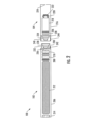
図1は、本開示の様々な例示的な実施形態による、制御本体102およびカートリッジ104を含むエアロゾル送達装置100の側面図を示す。具体的には、図1は、互いに連結された制御本体およびカートリッジを示す。制御本体およびカートリッジは、機能的な関係で着脱可能に位置合わせされてもよい。様々な機構がカートリッジを制御本体に接続して、ねじ係合、圧入係合、締まり嵌め、磁気係合などをもたらしてもよい。いくつかの例示的な実施形態では、カートリッジおよび制御本体が組み立てられた構成にある場合、エアロゾル送達装置は、実質的に棒状、実質的に管状または実質的に円筒形状であってよい。エアロゾル送達装置はまた、断面が実質的に長方形または菱形であってよく、これにより、扁平型電池を含む電源など、実質的に扁平または薄膜の電源との優れた適合性がもたらされ得る。カートリッジおよび制御本体は、多数の異なる材料のうちのいずれかから形成され得る別個のそれぞれのハウジングまたは外側本体を含んでもよい。ハウジングは、任意の好適な構造的に安定した材料から形成されてもよい。いくつかの例では、ハウジングは、ステンレス鋼、アルミニウムなどのような金属または合金から形成されてもよい。他の好適な材料は、様々なプラスチック(例えば、ポリカーボネート)、プラスチック上の金属めっき、セラミックなどを含む。
FIG. 1 shows a side view of an
いくつかの例示的な実施形態では、エアロゾル送達装置100の制御本体102またはカートリッジ104の一方または両方は、使い捨て可能であるか、再使用可能であると称され得る。例えば、制御本体は、交換可能なバッテリまたは再充電可能なスーパーキャパシタを有してもよく、したがって、典型的な壁コンセントへの接続、車の充電器(すなわち、シガーソケット)への接続、ユニバーサルシリアルバス(USB)ケーブルもしくはコネクタなどを介したコンピュータへの接続、無線周波数(RF)充電器への接続、または光電池(時に太陽電池と呼ばれる)、もしくは太陽電池のソーラーパネルへの接続を含む任意の種類の再充電技術と組み合わされてもよい。好適な再充電技術のいくつかの例を以下に記載する。さらに、いくつかの例示的な実施形態では、カートリッジは、参照によりその全体が本明細書に組み込まれるChangらの米国特許第8,910,639号明細書に開示されているような使い捨てカートリッジを含んでもよい。
In some exemplary embodiments, one or both of the
図2は、いくつかの例示的な実施形態によるエアロゾル送達装置100をさらに詳細に示す。そこに示されている切欠図に見られるように、この場合もやはり、エアロゾル送達装置は、各々が多数のそれぞれの構成要素を含む制御本体102およびカートリッジ104を含むことができる。図2に示される構成要素は、制御本体およびカートリッジ内に存在してもよい構成要素の代表であり、本開示に包含される構成要素の範囲を限定することを意図するものではない。示されるように、例えば、制御本体は、制御構成要素208(例えば、電子アナログ構成要素)、センサ210、電源212および1つ以上の発光ダイオード(LED)214(例えば、有機発光ダイオード(OLED))などの様々な電子的構成要素を含むことができる制御本体シェル206から形成することができ、そのような構成要素は、可変に位置合わせすることができる。流量センサは、加速度計、ジャイロスコープ、光学センサ、近接センサなどのような多数の好適なセンサを含んでもよい。
2 illustrates in further detail an
電源212は、参照により本明細書に組み込まれるSurらの米国特許出願番号第14/918926号明細書に開示されているように、リチウムイオン電池、固体電池またはスーパーキャパシタなどの好適な電源であり得るか、それらを含んでもよい。好適な固体電池の例は、STMicroelectronicsのEnFilm(TM)充電式固体リチウム薄膜電池を含む。好適なスーパーキャパシタの例は、電気二重層キャパシタ(EDLC)、ハイブリッドキャパシタ、例えば、リチウムイオンキャパシタ(LIC)などを含む。
The
いくつかの例示的な実施形態では、電源212は、制御構成要素208(例えば、アナログの電子的構成要素)に電流を送達するように構成された充電式電源であってよい。これらの例では、電源は、測温抵抗体(RTD)を介して充電回路に接続されてもよい。RTDは、電源の温度が閾値量を超えると充電回路に信号を送るように構成されてもよく、充電回路はそれに応答して電源の充電を無効にしてもよい。これらの例では、電源の安全な充電は、デジタルプロセッサ(例えば、マイクロプロセッサ)および/またはデジタル処理ロジックから独立して確保されてもよい。
In some exemplary embodiments, the
LED214は、エアロゾル送達装置100に備えられ得る好適な視覚インジケータの一例であり得る。いくつかの例では、LEDは、有機LEDまたは量子ドット対応LEDを含んでもよい。有機LEDまたは量子ドット対応LEDを含むLEDなどの視覚インジケータに加えて、またはその代わりとして、音声インジケータ(例えば、スピーカ)、触覚インジケータ(例えば、振動モータ)などのような他のインジケータを含めることができる。
The
カートリッジ104は、リザーバハウジング内に貯蔵されたエアロゾル前駆体組成物をヒータ222(時に加熱要素と呼ばれる)に吸い上げるか、そうでなければ輸送するように構成された液体輸送要素220と流体連通しているリザーバ218を囲むカートリッジシェル216から形成することができる。様々な構成では、この構造はタンクと呼ばれてもよく、したがって、「タンク」、「カートリッジ」などの用語は、エアロゾル前駆体組成物のリザーバを囲み、ヒータを含むシェルまたは他のハウジングを指すために区別なく使用されてもよい。いくつかの例では、リザーバとヒータとの間に弁が配置され得、リザーバからヒータに送られるか送達されるエアロゾル前駆体組成物の量を制御するように弁が構成されてもよい。
The
電流が印加されると熱を発生するように構成された様々な例の材料を使用して、ヒータ222を形成してもよい。これらの例のヒータは、ワイヤコイル、マイクロヒータなどのような抵抗加熱要素であってよい。ワイヤコイルを形成してもよい材料の例は、カンタル(FeCrAl)、ニクロム、二珪化モリブデン(MoSi2)、珪化モリブデン(MoSi)、アルミニウムをドープした二珪化モリブデン(Mo(Si,Al)2)、チタン(Ti)、黒鉛および黒鉛系材料(例えば、炭素系発泡体および糸)ならびにセラミック(例えば、正温度係数セラミックまたは負温度係数セラミック)を含む。本開示によるエアロゾル送達装置に有用なヒータまたは加熱部材の例示的な実施形態がさらに以下に記載され、本明細書に記載の図2に示すような装置に組み込むことができる。
Various example materials configured to generate heat when an electric current is applied thereto may be used to form the
形成されたエアロゾルをカートリッジ104から放出することを可能にするために、開口部224がカートリッジシェル216内に(例えば、マウスエンドに)存在してもよい。
An
ヒータ222に加えて、カートリッジ104はまた、1つ以上の他の電子的構成要素226を含んでもよい。これらの電子的構成要素は、集積回路、メモリ構成要素、センサなどを含んでもよい。電子的構成要素は、有線または無線手段によって、制御構成要素208および/または外部装置と通信するように適合されてもよい。電子的構成要素は、カートリッジまたはその基部228内のどこに配置されてもよい。
In addition to the
制御構成要素208およびセンサ210は別個に示されているが、制御構成要素およびセンサは電子回路基板として組み合わされてもよいことが理解される。さらに、電子回路基板は、電子回路基板が制御本体の中心軸に対して長さ方向に平行であり得るという点で、図1の図に対して水平に配置されてもよい。いくつかの例では、センサは、それが取り付けられ得るそれ自体の回路基板または他の基部要素を含んでもよい。いくつかの例では、フレキシブル回路基板が利用されてもよい。フレキシブル回路基板は、実質的に管状の形状を含む様々な形状に構成されてもよい。いくつかの例では、フレキシブル回路基板は、以下でさらに説明されるように、ヒータ基板と組み合わされるか、ヒータ基板上に積層されるか、ヒータ基板の一部または全部を形成してもよい。
Although the
制御本体102およびカートリッジ104は、それらの間の流体係合を容易にするように構成された構成要素を含んでもよい。図2に示すように、制御本体は、内部にキャビティ232を有するカプラ230を含むことができる。カートリッジの基部228は、カプラと係合するように構成することができ、キャビティ内に嵌合するように構成された突起234を含むことができる。このような係合は、制御本体とカートリッジとの間の安定した接続を容易にするとともに、制御本体内の電源212および制御構成要素208とカートリッジ内のヒータ222との間の電気的接続を確立することができる。さらに、制御本体シェル206は、吸気口236を含むことができ、吸気口236はシェル内のノッチであってよく、ここでノッチはカプラに接続し、これにより、カプラ周辺の周囲空気が通過してシェル内に入り、次いでカプラのキャビティ232を通過し、突起234を介してカートリッジ内に入ることが可能になる。
The
使用時には、ヒータ222をアクティブ化させてエアロゾル前駆体組成物の構成要素を気化させる。エアロゾル送達装置のマウスエンドを吸引すると、周囲空気が吸気口236に入り、カプラ230内のキャビティ232と、基部228の突起234内の中央開口部とを通過する。カートリッジ104では、吸引された空気が形成された蒸気と組み合わさって、エアロゾルを形成する。エアロゾルは、ヒータから吹き飛ばされるか、吸入されるか、そうでなければ吸引され、エアロゾル送達装置のマウスエンド内の開口部224から出る。
In use, the
本開示による有用なカプラおよび基部は、参照によりその全体が本明細書に組み込まれるNovakらの米国特許出願公開第2014/0261495号明細書に記載されている。例えば、図2に見られるように、カプラ230は、基部228の内周240と嵌合するように構成された外周238を画定してもよい。一実施形態では、基部の内周は、カプラの外周の半径と実質的に等しいか、それよりもわずかに大きい半径を画定してもよい。さらに、カプラは、基部の内周に画定された1つ以上の凹部244と係合するように構成された1つ以上の突出部242を外周に画定してもよい。しかし、様々な他の例の構造、形状および構成要素を使用して、基部をカプラに連結してもよい。いくつかの例では、カートリッジ104の基部と制御本体102のカプラとの間の接続が実質的に恒久的であってよいのに対して、他の例では、例えば、制御本体が、使い捨ておよび/または再充填可能であってよい1つ以上の追加のカートリッジとともに再利用され得るように、それらの間の接続は解放可能であってよい。
Useful couplers and bases according to the present disclosure are described in U.S. Patent Application Publication No. 2014/0261495 to Novak et al., which is incorporated herein by reference in its entirety. For example, as seen in FIG. 2, the
いくつかの例では、エアロゾル送達装置100は、実質的に棒状または実質的に管状または実質的に円筒形状であってよい。他の例では、追加の形状および寸法、例えば、長方形または三角形の断面、多面体形状などが包含される。
In some examples, the
図2に示すリザーバ218は、本明細書に記載されるように、容器であってもよいし、繊維質リザーバであってもよい。例えば、この例では、リザーバは、カートリッジシェル216の内部を取り囲むチューブの形状に実質的に形成された不織繊維の1つ以上の層を備えることができる。リザーバ内にエアロゾル前駆体組成物を保持することができる。例えば、リザーバによって液体構成要素を吸着して保持することができる。リザーバは、液体輸送要素220と流体接続することができる。この例では、液体輸送要素は、毛細管作用によって、金属ワイヤコイルの形態であるヒータ222に、リザーバ内に貯蔵されたエアロゾル前駆体組成物を輸送することができる。このように、ヒータは液体輸送要素を伴った加熱構成にある。本開示によるエアロゾル送達装置に有用なリザーバおよび輸送要素の例示的な実施形態がさらに以下に記載され、本明細書に記載の図2に示すような装置に、このようなリザーバおよび/または輸送要素を組み込むことができる。特に、以下にさらに説明する加熱部材と輸送要素との特定の組合せが、本明細書に記載の図2に示すような装置に組み込まれてもよい。
The
本開示によるエアロゾル送達装置の様々な構成要素は、当該技術分野に記載され市販されている構成要素から選択することができる。本開示に従って使用することができるバッテリの例は、参照によりその全体が本明細書に組み込まれるPeckerarらの米国特許出願公開第2010/0028766号明細書に記載されている。 The various components of the aerosol delivery device according to the present disclosure can be selected from those described in the art and commercially available. An example of a battery that can be used according to the present disclosure is described in U.S. Patent Application Publication No. 2010/0028766 to Peckerar et al., which is incorporated herein by reference in its entirety.
エアロゾル送達装置100は、エアロゾル発生が所望される場合に、ヒータ222への電力の供給を制御するためのセンサ210または別のセンサもしくは検出器を組み込むことができる。そのため、例えば、エアロゾル送達装置の場合にヒータへの給電をオフにし、吸引中にヒータによる熱の発生を作動させるか引き起こすために給電をオンにする様式または方法が提供される。追加の代表的な種類の感知または検出機構、それらの構造および構成、それらの構成要素ならびにそれらの一般的な動作方法は、いずれも参照によりその全体が本明細書に組み込まれるSprinkel,Jr.の米国特許第5,261,424号明細書、McCaffertyらの米国特許第5,372,148号明細書およびFlickのPCT特許出願公開WO2010/003480に記載されている。
The
エアロゾル送達装置100は、ヒータ222への電力量を制御するための制御構成要素208または別の制御機構を組み込むことが最も好ましい。代表的な種類の電子的構成要素、それらの構造および構成、それらの特徴ならびにそれらの一般的な動作方法は、いずれも参照によりその全体が本明細書に組み込まれるGerthらの米国特許第4,735,217号明細書、Brooksらの米国特許第4,947,874号明細書、McCaffertyらの米国特許第5,372,148号明細書、Fleischhauerらの米国特許第6,040,560号明細書、Nguyenらの米国特許第7,040,314号明細書、Panの米国特許第8,205,622号明細書、Fernandoらの米国特許出願公開第2009/0230117号明細書、Colletらの米国特許出願公開第2014/0060554号明細書、Ampoliniらの米国特許出願公開第2014/0270727号明細書および2014年3月13日に出願されたHenryらの米国特許出願番号第14/209,191号明細書に記載されている。
Most preferably, the
エアロゾル前駆体を支持するための代表的な種類の基材、リザーバまたは他の構成要素は、いずれも参照によりその全体が本明細書に組み込まれるNewtonの米国特許第8,528,569号明細書、Chapmanらの米国特許出願公開第2014/0261487号明細書、2013年8月28日に出願されたDavisらの米国特許出願番号第14/011,992号明細書および2014年2月3日に出願されたBlessらの米国特許出願番号第14/170,838号明細書に記載されている。さらに、様々なウィッキング材料ならびに特定の種類の電子タバコ内のそれらのウィッキング材料の構成および動作は、参照によりその全体が本明細書に組み込まれるSearsらの米国特許出願公開第2014/0209105号明細書に記載されている。 Representative types of substrates, reservoirs or other components for supporting the aerosol precursor are described in U.S. Patent Application Publication No. 8,528,569 to Newton, U.S. Patent Application Publication No. 2014/0261487 to Chapman et al., U.S. Patent Application No. 14/011,992 to Davis et al., filed August 28, 2013, and U.S. Patent Application No. 14/170,838 to Bless et al., filed February 3, 2014, all of which are incorporated herein by reference in their entireties. Additionally, various wicking materials and the configuration and operation of those wicking materials within certain types of electronic cigarettes are described in U.S. Patent Application Publication No. 2014/0209105 to Sears et al., which are incorporated herein by reference in their entireties.
蒸気前駆体組成物とも呼ばれるエアロゾル前駆体組成物は、例えば、多価アルコール(例えば、グリセリン、プロピレングリコールまたはそれらの混合物)、ニコチン、タバコ、タバコ抽出物および/または風味料を含む様々な構成要素を備えてもよい。代表的な種類のエアロゾル前駆体構成要素および製剤もまた、Robinsonらの米国特許第7,217,320号明細書ならびにZhengらの米国特許公開第2013/0008457号明細書、Chongらの米国特許公開第2013/0213417号明細書、Collettらの米国特許公開第2014/0060554号明細書、Lipowiczらの米国特許公開第2015/0020823号明細書およびKollerの米国特許公開第2015/0020830号明細書、ならびにBowenらのWO2014/182736号に記載され、特徴付けられており、これらの開示は参照により本明細書に組み込まれる。使用されてもよい他のエアロゾル前駆体は、R.J.Reynolds Vapor CompanyのVUSE(R)製品、Imperial Tobacco Group PLCのBLU(TM)製品、Mistic EcigsのMISTIC MENTHOL製品およびCN Creative Ltd.のVYPE製品に組み込まれているエアロゾル前駆体を含む。Johnson Creek Enterprises LLCから入手可能な電子タバコ用のいわゆる「スモークジュース」も望ましい。 The aerosol precursor composition, also referred to as a vapor precursor composition, may comprise a variety of components including, for example, a polyhydric alcohol (e.g., glycerin, propylene glycol or mixtures thereof), nicotine, tobacco, tobacco extracts and/or flavorants. Representative types of aerosol precursor components and formulations are also described and characterized in U.S. Patent No. 7,217,320 to Robinson et al., and U.S. Patent Publication No. 2013/0008457 to Zheng et al., U.S. Patent Publication No. 2013/0213417 to Chong et al., U.S. Patent Publication No. 2014/0060554 to Collett et al., U.S. Patent Publication No. 2015/0020823 to Lipowicz et al., and U.S. Patent Publication No. 2015/0020830 to Koller, and WO 2014/182736 to Bowen et al., the disclosures of which are incorporated herein by reference. Other aerosol precursors that may be used are described in U.S. Patent No. 7,217,320 to Robinson et al., and U.S. Patent Publication No. 2013/0213417 to Chong et al., and U.S. Patent Publication No. 2014/0060554 to Collett et al., and U.S. Patent Publication No. 2015/0020823 to Lipowicz et al., and U.S. Patent Publication No. 2015/0020830 to Koller, and WO 2014/182736 to Bowen et al., the disclosures of which are incorporated herein by reference. These include the aerosol precursors incorporated in Reynolds Vapor Company's VUSE® products, Imperial Tobacco Group PLC's BLU™ products, Mystic Ecigs' MISTIC MENTHOL products, and CN Creative Ltd.'s VYPE products. Also desirable are so-called "smoke juices" for e-cigarettes available from Johnson Creek Enterprises LLC.
視覚インジケータおよび関連構成要素、音声インジケータ、触覚インジケータなど、視覚的刺激をもたらす構成要素、またはインジケータの追加の代表的な種類がエアロゾル送達装置100に使用されてもよい。好適なLED構成要素の例ならびにそれらの構成および使用は、いずれも参照によりその全体が本明細書に組み込まれるSprinkelらの米国特許第5,154,192号明細書、Newtonの米国特許第8,499,766号明細書、Scatterdayの米国特許第8,539,959号明細書および2014年2月5日に出願されたSearsらの米国特許出願番号第14/173,266号明細書に記載されている。
Additional representative types of components or indicators that provide visual cues, such as visual indicators and related components, audio indicators, tactile indicators, etc., may be used in the
本開示のエアロゾル送達装置に組み込むことができるさらに他の特徴、制御部または構成要素は、いずれも参照によりその全体が本明細書に組み込まれるHarrisらの米国特許第5,967,148号明細書、Watkinsらの米国特許第5,934,289号明細書、Countsらの米国特許第5,954,979号明細書、Fleischhauerらの米国特許第6,040,560号明細書、Honの米国特許第8,365,742号明細書、Fernandoらの米国特許第8,402,976号明細書、Kataseの米国特許出願公開第2005/0016550号明細書、Fernandoらの米国特許出願公開第2010/0163063号明細書、Tuckerらの米国特許出願公開第2013/0192623号明細書、Levenらの米国特許出願公開第2013/0298905号明細書、Kimらの米国特許出願公開第2013/0180553号明細書、Sebastianらの米国特許出願公開第2014/0000638号明細書、Novakらの米国特許出願公開第2014/0261495号明細書およびDePianoらの米国特許出願公開第2014/0261408号明細書に記載されている。 Further features, controls or components that may be incorporated into the aerosol delivery devices of the present disclosure are described in U.S. Pat. No. 5,967,148 to Harris et al., U.S. Pat. No. 5,934,289 to Watkins et al., U.S. Pat. No. 5,954,979 to Counts et al., U.S. Pat. No. 6,040,560 to Fleischhauer et al., U.S. Pat. No. 8,365,742 to Hon, U.S. Pat. No. 8,402,976 to Fernando et al., U.S. Pat. App. Pub. No. 2005/00363 to Katase, all of which are incorporated herein by reference in their entireties. No. 16550, U.S. Patent Application Publication No. 2010/0163063 to Fernando et al., U.S. Patent Application Publication No. 2013/0192623 to Tucker et al., U.S. Patent Application Publication No. 2013/0298905 to Leven et al., U.S. Patent Application Publication No. 2013/0180553 to Kim et al., U.S. Patent Application Publication No. 2014/0000638 to Sebastian et al., U.S. Patent Application Publication No. 2014/0261495 to Novak et al., and U.S. Patent Application Publication No. 2014/0261408 to DePiano et al.
制御構成要素208は、多数の電子的構成要素を含み、いくつかの例では、電子的構成要素を支持し電気的に接続するプリント回路板(PCB)から形成されてもよい。電子的構成要素は、デジタルプロセッサ(例えば、マイクロプロセッサ)および/またはデジタル処理ロジックから独立して動作するように構成されたアナログの電子的構成要素を含んでもよい。いくつかの例では、制御構成要素は、1つ以上のネットワーク、コンピューティング装置または他の適切に対応された装置との無線通信を可能にするために通信インターフェースに連結されてもよい。好適な通信インターフェースの例は、2015年3月4日に出願されたMarionらの米国特許出願番号第14/638,562号明細書に開示されており、その内容は参照によりその全体が組み込まれる。エアロゾル送達装置が無線通信するように構成されてもよい好適な様式の例は、2014年7月10日に出願されたAmpoliniらの米国特許出願番号第14/327,776号明細書および2015年1月29日に出願されたHenry,Jr.らの米国特許出願番号第14/609,032号明細書に開示されており、それらの各々は参照によりその全体が本明細書に組み込まれる。
The
前述のように、制御本体102は、ヒータ222への電力量を制御するための制御構成要素208を含んでもよい。いくつかの例示的な実施形態では、制御構成要素は、ユーザ入力に応答してヒータに定電流を導き、それによってユーザ入力に応答してヒータをアクティブ化させて、エアロゾル前駆体組成物の構成要素を気化させるように構成されているアナログの電子的構成要素であり得るか、それを含んでもよい。アナログの電子的構成要素は、デジタルプロセッサから独立してヒータに定電流を導くように構成されてもよい。すなわち、アナログの電子的構成要素は、デジタルプロセッサを使用せずにヒータに定電流を導いてもよい。したがって、いくつかの例では、エアロゾル送達装置100からデジタルプロセッサが省略されてもよい。
As previously mentioned, the
さらに具体的な例では、制御構成要素208は、非反転オペアンプ、リニアレギュレータ、または一定の出力電流を維持するように構成された別の好適な電子的構成要素などのアナログの電子的構成要素を含んでもよい。使用され得る例示的な非反転オペアンプは、Texas Instruments(TM)の高電圧高電流オペアンプ(「OPA549」)Burr-Brown製品を含む。使用され得る例示的なリニアレギュレータは、Linear Technology(TM)の1.5アンペア(A)モニタ付き単一抵抗型の堅牢なリニアレギュレータまたは1.5A定電流レギュレータ(「LT3081ER」)製品を含む。
In a more specific example, the
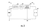
図3は、いくつかの例示的な実施形態による、アナログの電子的構成要素302(例えば、非反転オペアンプ、リニアレギュレータ)を含む制御構成要素208を有する制御本体102をさらに詳細に示す。電源212は、制御本体102の様々な構成要素を含む電気的負荷に接続されて、アナログの電子的構成要素を含む電気回路を形成してもよい。さらに具体的には、アナログの電子的構成要素は、電源と連結されて、そこから電流を受け取ってもよい。前述のように、アナログの電子的構成要素はそこからヒータ222に定電流を導いてもよく、制御本体がカートリッジ104と連結された場合にはヒータも電気的負荷に含められ得る。
3 illustrates in more detail the
アナログの電子的構成要素302は、ユーザ入力に応答して、ヒータ222に定電流を導くように構成されてもよい。したがって、制御本体102は、ユーザ入力インターフェース304も含んでもよく、ユーザ入力インターフェース304を介してユーザ入力が受け取り可能である。いくつかの例では、制御本体102は、ユーザ入力インターフェースとアナログの電子的構成要素との間に連結され、電源212からアナログの電子的構成要素、次いで、アナログの電子的構成要素からヒータに導かれている電流の視覚的インジケーションを提供するように構成されたインジケータ306をさらに備えてもよい。
The analog
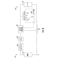
図4に示すように、いくつかの例では、ユーザ入力インターフェース304は、機械的スイッチ402(例えば、押しボタン)と、機械的スイッチに連結された固体スイッチ404(例えば、ラッチングスイッチ)とを含み、機械的スイッチ402を介してユーザ入力が受け取り可能である。特に、固体スイッチは、アナログの電子的構成要素302と機械的スイッチとの間に連結され、そこからのユーザ入力に応答して、電流をアナログの電子的構成要素に切り替えてもよい。これにより、固体スイッチはまた、アナログの電子的構成要素によって導かれる定電流をヒータ222に切り替えてもよい。これらの例では、インジケータ306は、固体スイッチとアナログの電子的構成要素との間に連結されてもよく、さらに具体的には、切り替えられている電流の視覚的インジケーションを提供するように構成されてもよい。
4, in some examples, the
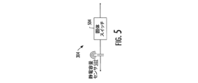
図5に示すように、機械的スイッチ402に加えて、またはその代わりに、ユーザ入力インターフェース304は、静電容量センサ502を含んでもよく、静電容量センサ502を介してユーザ入力が受け取り可能である。静電容量センサは、物体とのいかなる物理的接触も必要とすることなく、近くの物体を検出するように構成されてもよい。特に、静電容量センサは、参照により本明細書に組み込まれるSurらの米国特許出願番号第14/988496号明細書に記載されているように、ユーザの指または他の機器などの近くの物体の存在下で静電容量の変化を測定して、ユーザ入力をもたらしてもよい。
5, in addition to or instead of the mechanical switch 402, the
静電容量センサ502はまた、固体スイッチ504に連結されてもよく、これは、機械的スイッチ402および静電容量センサの両方を含む例では、固体スイッチ404によって成り立ち得る。固体スイッチは、そこからのユーザ入力に応答して電流をアナログの電子的構成要素302に切り替え、それによって、アナログの電子的構成要素によって導かれる定電流もヒータ222に切り替えてもよい。特に、機械的スイッチまたは静電容量センサは、ユーザ入力に応答して固体スイッチにイネーブル信号を送信してもよく、固体スイッチは、イネーブル信号に応答して、電流が電源212からアナログの電子的構成要素に、およびアナログの電子的構成要素からヒータに導かれる状態をアクティブ化または非アクティブ化させてもよい。
The capacitance sensor 502 may also be coupled to a solid-
図6に示すように、いくつかの例示的な実施形態では、制御本体102は、ロータリースイッチまたはサムホイールスイッチなどの単極多投(SPMT)スイッチ602を含んでもよい。示されるように、SPMTスイッチは、ヒータ222の電力設定を変更するために、極Pに選択的に接続可能である複数の投T1、T2、T3、T4を含む。複数の投T1、T2、T3、T4は、それぞれ異なる抵抗値を有するそれぞれの抵抗器R1、R2、R3、R4に連結されてもよい。アナログの電子的構成要素302とヒータ222との間に複数の抵抗器を連結して、それらの間に導かれる定電流が、どの投が極に接続されるかに応じて変化するアンペア数を有し得、それによってヒータが可変電力設定を有し得るようにしてもよい。図示された例は、それぞれ極に接続され得る4つの投を描いているが、SPMT602スイッチは、それぞれ極に接続され得る任意の数の投を含んでもよいことに留意されたい。
As shown in FIG. 6, in some exemplary embodiments, the
前述のように、いくつかの例では、アナログの電子的構成要素302は、Linear Technology(TM)のモニタ付き1.5アンペアの単一抵抗型の堅牢なリニアレギュレータ製品であり得るか、それを含んでもよい。これらの例では、リニアレギュレータは、それぞれ異なる抵抗値を有するそれぞれの抵抗器R1、R2、R3、R4に連結された複数の投T1、T2、T3、T4を有するSPMT602を通じてプログラムされ得るプログラム可能な電流制限回路を含んでもよい。
As mentioned above, in some examples, the analog
図2を再び参照すると、制御本体102に加えて、またはその代わりに、カートリッジ104の電子的構成要素226は、図3~図6を参照して上述したような制御本体のアナログの電子的構成要素302と同様に構成され機能してもよいアナログの電子的構成要素を含んでもよい。例えば、電子的構成要素は、制御本体がカートリッジと連結された場合に、電源212に連結されるアナログの電子的構成要素を含んでもよい。アナログの電子的構成要素は、ユーザ入力に応答して電源から電流を受け取り、それによってヒータ222に定電流を導き、それによってユーザ入力に応答してヒータをアクティブ化させて、エアロゾル前駆体組成物の構成要素を気化させるように構成されてもよい。特に、アナログの電子的構成要素は、デジタルプロセッサの使用を必要とせずに、ヒータに定電流を導くことを開始するか、そうでなければ導くことをさらに達成するなど、デジタルプロセッサから独立してヒータに定電流を導くように構成されてもよい。
2, in addition to or instead of the
物品の使用の上記の説明は、本明細書に提供されるさらなる開示に照らして当業者には明らかであり得る軽微な変更を介して、本明細書に記載される様々な例示的な実施形態に適用され得る。しかし、上記の使用の説明は、物品の使用を限定することを意図するものではなく、本開示のすべての必要な開示要件に従うために提供される。図1から図6に示されたか、そうでなければ上記に記載された物品に示された要素はいずれも、本開示によるエアロゾル送達装置に含まれ得る。 The above description of the use of the article may be applied to the various exemplary embodiments described herein through minor modifications that may be apparent to one of ordinary skill in the art in light of the further disclosure provided herein. However, the above description of the use is not intended to limit the use of the article, but is provided to comply with all necessary disclosure requirements of the present disclosure. Any of the elements shown in Figures 1 through 6 or otherwise described above in the article may be included in an aerosol delivery device according to the present disclosure.
上記の説明および関連する図面に示された教示の利益を有し、本開示が関連する当業者には、本明細書に記載された開示の多くの変更および他の実施形態が思い浮かぶであろう。したがって、本開示は、開示された特定の実施形態に限定されるものではなく、変更および他の実施形態が添付の特許請求の範囲内に含まれることが意図されることが理解されるべきである。さらに、上記の説明および関連する図面は、要素および/または機能の特定の例の組合せに照らして例示的な実施形態を記載しているが、添付の特許請求の範囲から逸脱することなく、代替的な実施形態によって要素および/または機能の異なる組合せが提供されてもよいことが理解されるべきである。これに関して、例えば、添付の特許請求の範囲のいくつかに記載され得るように、明示的に上述されたもの以外の要素および/または機能の異なる組合せも考えられる。本明細書では特定の用語を使用しているが、それらは一般的かつ説明的な意味でのみ使用され、限定のために使用されない。 Many modifications and other embodiments of the disclosures described herein will occur to one skilled in the art to which this disclosure pertains having the benefit of the teachings presented in the above description and the associated drawings. It is therefore to be understood that the disclosure is not limited to the specific embodiments disclosed, and that modifications and other embodiments are intended to be included within the scope of the appended claims. Furthermore, while the above description and the associated drawings describe exemplary embodiments in the context of certain example combinations of elements and/or features, it is to be understood that different combinations of elements and/or features may be provided by alternative embodiments without departing from the scope of the appended claims. In this regard, different combinations of elements and/or features other than those expressly described above are also contemplated, for example, as may be set forth in some of the appended claims. Although specific terms are used herein, they are used in a generic and descriptive sense only and not for purposes of limitation.
Claims (10)
少なくとも1つのハウジングと、少なくとも1つのハウジング内に収容された、
エアロゾル送達装置に電力を供給する電源と、
加熱要素と、
エアロゾル前駆体組成物を保持するように構成されたリザーバと、
アナログの電子的構成要素であって、非反転オペアンプを含み、ユーザ入力に応答して、およびデジタルプロセッサから独立して、加熱要素に定電流を導いて、加熱要素をアクティブ化させ、エアロゾル前駆体組成物の構成要素を気化させるように構成された、当該アナログの電子的構成要素と、
ユーザ入力インターフェースであって、当該ユーザ入力インターフェースを介してユーザ入力が受け取り可能であり、当該ユーザ入力インターフェースが、
機械的スイッチであって、当該機械的スイッチを介してユーザ入力が受け取り可能である、当該機械的スイッチと、
アナログの電子的構成要素および機械的スイッチの間でアナログの電子的構成要素および機械的スイッチに動作可能に連結されたラッチングスイッチであって、機械的スイッチへのユーザ入力に応答して、アクティブ化させ、アナログの電子的構成要素に電流を切り替え、それにより、非アクティブ化させ、アナログの電子的構成要素から電流を切り替える機械的スイッチへの更なるユーザ入力まで、アナログの電子的構成要素によって導かれる定電流を加熱要素に切り替える当該ラッチングスイッチ、で構成された固体スイッチと
を含む、
当該ユーザ入力インターフェースと、
インジケータであって、ユーザ入力インターフェースの固体スイッチとアナログの電子的構成要素との間に動作可能に連結され、切り替えられている定電流の視覚的インディケーションを提供するように構成された、当該インジケータと
を備える、エアロゾル送達装置。 1. An aerosol delivery device comprising:
At least one housing; and a sensor housed within the at least one housing.
a power source for powering the aerosol delivery device;
A heating element;
a reservoir configured to hold an aerosol precursor composition;
an analog electronic component including a non-inverting op-amp configured to, in response to a user input and independent of the digital processor, direct a constant current to the heating element to activate the heating element and vaporize components of the aerosol precursor composition;
a user input interface through which user input can be received, the user input interface comprising:
a mechanical switch, the mechanical switch being capable of receiving a user input; and
a solid-state switch comprising: a latching switch operatively coupled between the analog electronic component and the mechanical switch, the latching switch responsive to a user input to the mechanical switch activating and switching current to the analog electronic component, thereby deactivating and switching a constant current conducted by the analog electronic component to the heating element until further user input to the mechanical switch which switches current from the analog electronic component;
said user input interface;
An aerosol delivery device comprising: an indicator operably coupled between a solid-state switch of a user input interface and an analog electronic component, the indicator configured to provide a visual indication of a constant current being switched.
少なくとも1つのハウジングを備え、少なくとも1つのハウジング内に収容された、
エアロゾル送達装置に電力を供給する電源と、
アナログの電子的構成要素であって、非反転オペアンプを含み、ユーザ入力に応答して、およびデジタルプロセッサから独立して、加熱要素に定電流を導いて、加熱要素をアクティブ化させ、エアロゾル前駆体組成物の構成要素を気化させるように構成された、アナログの電子的構成要素と、
ユーザ入力インターフェースであって、当該ユーザ入力インターフェースを介してユーザ入力が受け取り可能であり、当該ユーザ入力インターフェースが、
機械的スイッチであって、当該機械的スイッチを介してユーザ入力が受け取り可能である、当該機械的スイッチと、
アナログの電子的構成要素および機械的スイッチの間でアナログの電子的構成要素および機械的スイッチに動作可能に連結されたラッチングスイッチであって、機械的スイッチへのユーザ入力に応答して、アクティブ化させ、アナログの電子的構成要素に電流を切り替え、それにより、非アクティブ化させ、アナログの電子的構成要素から電流を切り替える機械的スイッチへの更なるユーザ入力に応答まで、アナログの電子的構成要素によって導かれる定電流を加熱要素に切り替える当該ラッチングスイッチ、で構成された固体スイッチと
を含む、
当該ユーザ入力インターフェースと、
インジケータであって、ユーザ入力インターフェースの固体スイッチとアナログの電子的構成要素との間に動作可能に連結され、切り替えられている定電流の視覚的インディケーションを提供するように構成された、当該インジケータと
を備える、制御本体。 a control body coupled or connectable to a cartridge comprising a heating element and containing an aerosol precursor composition, the control body being coupled or connectable to the cartridge to form an aerosol delivery device, the control body comprising:
The device includes at least one housing and is housed within the at least one housing.
a power source for powering the aerosol delivery device;
an analog electronic component including a non-inverting op-amp configured to, in response to a user input and independent of the digital processor, direct a constant current to the heating element to activate the heating element and vaporize components of the aerosol precursor composition;
a user input interface through which user input can be received, the user input interface comprising:
a mechanical switch, the mechanical switch being capable of receiving a user input; and
a solid state switch comprising: a latching switch operatively coupled between the analog electronic component and the mechanical switch, the latching switch responsive to a user input to the mechanical switch activating and switching current to the analog electronic component, thereby switching a constant current conducted by the analog electronic component to the heating element until responsive to a further user input to the mechanical switch deactivating and switching current from the analog electronic component .
said user input interface;
and an indicator operably coupled between a solid-state switch of the user input interface and the analog electronic component, the indicator configured to provide a visual indication of a constant current being switched.
Applications Claiming Priority (4)
| Application Number | Priority Date | Filing Date | Title |
|---|---|---|---|
| US15/261,336 US12472316B2 (en) | 2016-09-09 | 2016-09-09 | Analog control component for an aerosol delivery device |
| US15/261,336 | 2016-09-09 | ||
| PCT/IB2017/055399 WO2018047095A1 (en) | 2016-09-09 | 2017-09-07 | Analog control component for an aerosol delivery device |
| JP2019513351A JP2019528711A (en) | 2016-09-09 | 2017-09-07 | Analog control components for aerosol delivery devices |
Related Parent Applications (1)
| Application Number | Title | Priority Date | Filing Date |
|---|---|---|---|
| JP2019513351A Division JP2019528711A (en) | 2016-09-09 | 2017-09-07 | Analog control components for aerosol delivery devices |
Publications (2)
| Publication Number | Publication Date |
|---|---|
| JP2024028903A JP2024028903A (en) | 2024-03-05 |
| JP7698024B2 true JP7698024B2 (en) | 2025-06-24 |
Family
ID=60001958
Family Applications (2)
| Application Number | Title | Priority Date | Filing Date |
|---|---|---|---|
| JP2019513351A Pending JP2019528711A (en) | 2016-09-09 | 2017-09-07 | Analog control components for aerosol delivery devices |
| JP2023206892A Active JP7698024B2 (en) | 2016-09-09 | 2023-12-07 | Analog control components for an aerosol delivery device |
Family Applications Before (1)
| Application Number | Title | Priority Date | Filing Date |
|---|---|---|---|
| JP2019513351A Pending JP2019528711A (en) | 2016-09-09 | 2017-09-07 | Analog control components for aerosol delivery devices |
Country Status (9)
| Country | Link |
|---|---|
| US (2) | US12472316B2 (en) |
| EP (2) | EP4643914A3 (en) |
| JP (2) | JP2019528711A (en) |
| KR (2) | KR102574142B1 (en) |
| CN (1) | CN109688851B (en) |
| CA (1) | CA3033158A1 (en) |
| PL (1) | PL3509449T3 (en) |
| RU (1) | RU2740355C2 (en) |
| WO (1) | WO2018047095A1 (en) |
Families Citing this family (8)
| Publication number | Priority date | Publication date | Assignee | Title |
|---|---|---|---|---|
| EP3666095A4 (en) * | 2017-08-09 | 2021-11-24 | KT&G Corporation | AEROSOL GENERATION DEVICE AND REGULATION PROCESS FOR AEROSOL GENERATION DEVICE |
| GB201805234D0 (en) | 2018-03-29 | 2018-05-16 | Nicoventures Trading Ltd | Aerosol generating device |
| US11094993B2 (en) * | 2018-08-10 | 2021-08-17 | Rai Strategic Holdings, Inc. | Charge circuitry for an aerosol delivery device |
| US11456480B2 (en) * | 2019-02-07 | 2022-09-27 | Rai Strategic Holdings, Inc. | Non-inverting amplifier circuit for an aerosol delivery device |
| EP3711514A1 (en) * | 2019-03-22 | 2020-09-23 | Nerudia Limited | Smoking substitute system |
| CN110338465B (en) * | 2019-07-16 | 2024-10-15 | 深圳麦克韦尔科技有限公司 | Scavenging valve and electronic atomizing device |
| BR112022009973A2 (en) * | 2019-11-28 | 2022-08-09 | Chiesi Farm Spa | ELECTRONIC MODULE FOR AN INHALER AND INHALER ASSEMBLY COMPRISING THE ELECTRONIC MODULE |
| AR121656A1 (en) | 2020-03-26 | 2022-06-29 | Rai Strategic Holdings Inc | METHODS, APPARATUS AND SYSTEMS FOR ACTIVATING A DEVICE BEFORE OPERATING THE DEVICE |
Citations (3)
| Publication number | Priority date | Publication date | Assignee | Title |
|---|---|---|---|---|
| JP2008253001A (en) | 2007-03-29 | 2008-10-16 | Fujitsu Microelectronics Ltd | Switching regulator control circuit, linear regulator control circuit, power supply device having the switching regulator, and power supply device having the linear regulator |
| US20140299137A1 (en) | 2013-04-05 | 2014-10-09 | Johnson Creek Enterprises, LLC | Electronic cigarette and method and apparatus for controlling the same |
| US20160206001A1 (en) | 2015-01-19 | 2016-07-21 | Ryan L. Eng | Electronic hookah apparatus |
Family Cites Families (206)
| Publication number | Priority date | Publication date | Assignee | Title |
|---|---|---|---|---|
| US2057353A (en) | 1936-10-13 | Vaporizing unit fob therapeutic | ||
| US1771366A (en) | 1926-10-30 | 1930-07-22 | R W Cramer & Company Inc | Medicating apparatus |
| US2104266A (en) | 1935-09-23 | 1938-01-04 | William J Mccormick | Means for the production and inhalation of tobacco fumes |
| US3200819A (en) | 1963-04-17 | 1965-08-17 | Herbert A Gilbert | Smokeless non-tobacco cigarette |
| US4284089A (en) | 1978-10-02 | 1981-08-18 | Ray Jon P | Simulated smoking device |
| US4303083A (en) | 1980-10-10 | 1981-12-01 | Burruss Jr Robert P | Device for evaporation and inhalation of volatile compounds and medications |
| SE8405479D0 (en) | 1984-11-01 | 1984-11-01 | Nilsson Sven Erik | WANT TO ADMINISTER VOCABULARY, PHYSIOLOGY, ACTIVE SUBJECTS AND DEVICE FOR THIS |
| US4735217A (en) | 1986-08-21 | 1988-04-05 | The Procter & Gamble Company | Dosing device to provide vaporized medicament to the lungs as a fine aerosol |
| GB8713645D0 (en) | 1987-06-11 | 1987-07-15 | Imp Tobacco Ltd | Smoking device |
| US5019122A (en) | 1987-08-21 | 1991-05-28 | R. J. Reynolds Tobacco Company | Smoking article with an enclosed heat conductive capsule containing an aerosol forming substance |
| US4922901A (en) | 1988-09-08 | 1990-05-08 | R. J. Reynolds Tobacco Company | Drug delivery articles utilizing electrical energy |
| US4947875A (en) | 1988-09-08 | 1990-08-14 | R. J. Reynolds Tobacco Company | Flavor delivery articles utilizing electrical energy |
| US4947874A (en) | 1988-09-08 | 1990-08-14 | R. J. Reynolds Tobacco Company | Smoking articles utilizing electrical energy |
| US4986286A (en) | 1989-05-02 | 1991-01-22 | R. J. Reynolds Tobacco Company | Tobacco treatment process |
| US4945931A (en) | 1989-07-14 | 1990-08-07 | Brown & Williamson Tobacco Corporation | Simulated smoking device |
| US5154192A (en) | 1989-07-18 | 1992-10-13 | Philip Morris Incorporated | Thermal indicators for smoking articles and the method of application of the thermal indicators to the smoking article |
| US5408574A (en) | 1989-12-01 | 1995-04-18 | Philip Morris Incorporated | Flat ceramic heater having discrete heating zones |
| US5093894A (en) | 1989-12-01 | 1992-03-03 | Philip Morris Incorporated | Electrically-powered linear heating element |
| US5060671A (en) | 1989-12-01 | 1991-10-29 | Philip Morris Incorporated | Flavor generating article |
| US5144962A (en) | 1989-12-01 | 1992-09-08 | Philip Morris Incorporated | Flavor-delivery article |
| US5042510A (en) | 1990-01-08 | 1991-08-27 | Curtiss Philip F | Simulated cigarette |
| US5726421A (en) | 1991-03-11 | 1998-03-10 | Philip Morris Incorporated | Protective and cigarette ejection system for an electrical smoking system |
| US5249586A (en) | 1991-03-11 | 1993-10-05 | Philip Morris Incorporated | Electrical smoking |
| US5530225A (en) | 1991-03-11 | 1996-06-25 | Philip Morris Incorporated | Interdigitated cylindrical heater for use in an electrical smoking article |
| US5505214A (en) | 1991-03-11 | 1996-04-09 | Philip Morris Incorporated | Electrical smoking article and method for making same |
| US5261424A (en) | 1991-05-31 | 1993-11-16 | Philip Morris Incorporated | Control device for flavor-generating article |
| CA2466075C (en) | 1992-03-25 | 2007-05-01 | Japan Tobacco, Inc. | Components for smoking articles and process for making same |
| US5353813A (en) | 1992-08-19 | 1994-10-11 | Philip Morris Incorporated | Reinforced carbon heater with discrete heating zones |
| US5322075A (en) | 1992-09-10 | 1994-06-21 | Philip Morris Incorporated | Heater for an electric flavor-generating article |
| US5369723A (en) | 1992-09-11 | 1994-11-29 | Philip Morris Incorporated | Tobacco flavor unit for electrical smoking article comprising fibrous mat |
| US5498850A (en) | 1992-09-11 | 1996-03-12 | Philip Morris Incorporated | Semiconductor electrical heater and method for making same |
| US5441060A (en) | 1993-02-08 | 1995-08-15 | Duke University | Dry powder delivery system |
| US5372148A (en) | 1993-02-24 | 1994-12-13 | Philip Morris Incorporated | Method and apparatus for controlling the supply of energy to a heating load in a smoking article |
| US5468936A (en) | 1993-03-23 | 1995-11-21 | Philip Morris Incorporated | Heater having a multiple-layer ceramic substrate and method of fabrication |
| US5666977A (en) | 1993-06-10 | 1997-09-16 | Philip Morris Incorporated | Electrical smoking article using liquid tobacco flavor medium delivery system |
| EP0706352B1 (en) | 1993-06-29 | 2002-03-20 | Ponwell Enterprises Limited | Dispenser |
| US5388574A (en) | 1993-07-29 | 1995-02-14 | Ingebrethsen; Bradley J. | Aerosol delivery article |
| CH686872A5 (en) | 1993-08-09 | 1996-07-31 | Disetronic Ag | Medical Inhalationsgeraet. |
| DE4328243C1 (en) | 1993-08-19 | 1995-03-09 | Sven Mielordt | Smoke or inhalation device |
| IE72523B1 (en) | 1994-03-10 | 1997-04-23 | Elan Med Tech | Nicotine oral delivery device |
| US5649554A (en) | 1995-10-16 | 1997-07-22 | Philip Morris Incorporated | Electrical lighter with a rotatable tobacco supply |
| US5564442A (en) | 1995-11-22 | 1996-10-15 | Angus Collingwood MacDonald | Battery powered nicotine vaporizer |
| US5743251A (en) | 1996-05-15 | 1998-04-28 | Philip Morris Incorporated | Aerosol and a method and apparatus for generating an aerosol |
| EP0845220B1 (en) | 1996-06-17 | 2003-09-03 | Japan Tobacco Inc. | Flavor producing article |
| CN1113621C (en) | 1996-06-17 | 2003-07-09 | 日本烟业产业株式会社 | Flavor generating product and flavor generating tool |
| US6089857A (en) | 1996-06-21 | 2000-07-18 | Japan Tobacco, Inc. | Heater for generating flavor and flavor generation appliance |
| US6040560A (en) | 1996-10-22 | 2000-03-21 | Philip Morris Incorporated | Power controller and method of operating an electrical smoking system |
| US5934289A (en) | 1996-10-22 | 1999-08-10 | Philip Morris Incorporated | Electronic smoking system |
| US5878752A (en) | 1996-11-25 | 1999-03-09 | Philip Morris Incorporated | Method and apparatus for using, cleaning, and maintaining electrical heat sources and lighters useful in smoking systems and other apparatuses |
| US5865186A (en) | 1997-05-21 | 1999-02-02 | Volsey, Ii; Jack J | Simulated heated cigarette |
| KR100289448B1 (en) | 1997-07-23 | 2001-05-02 | 미즈노 마사루 | Flavor generator |
| US5954979A (en) | 1997-10-16 | 1999-09-21 | Philip Morris Incorporated | Heater fixture of an electrical smoking system |
| US5967148A (en) | 1997-10-16 | 1999-10-19 | Philip Morris Incorporated | Lighter actuation system |
| DK0923957T3 (en) | 1997-11-19 | 2002-02-18 | Microflow Eng Sa | Nozzle blank and liquid droplet spray device for an inhaler suitable for respiratory therapy |
| CN1044314C (en) | 1997-12-01 | 1999-07-28 | 蒲邯名 | Healthy cigarette |
| US6164287A (en) | 1998-06-10 | 2000-12-26 | R. J. Reynolds Tobacco Company | Smoking method |
| US6095153A (en) | 1998-06-19 | 2000-08-01 | Kessler; Stephen B. | Vaporization of volatile materials |
| US6234167B1 (en) | 1998-10-14 | 2001-05-22 | Chrysalis Technologies, Incorporated | Aerosol generator and methods of making and using an aerosol generator |
| US6053176A (en) | 1999-02-23 | 2000-04-25 | Philip Morris Incorporated | Heater and method for efficiently generating an aerosol from an indexing substrate |
| US6196218B1 (en) | 1999-02-24 | 2001-03-06 | Ponwell Enterprises Ltd | Piezo inhaler |
| US6601776B1 (en) | 1999-09-22 | 2003-08-05 | Microcoating Technologies, Inc. | Liquid atomization methods and devices |
| DE60139307D1 (en) | 2000-03-23 | 2009-09-03 | Pmpi Llc | ELECTRICAL SMOKE SYSTEM AND METHOD |
| US7559324B2 (en) | 2000-06-21 | 2009-07-14 | Fisher & Paykel Healthcare Limited | Conduit with heated wick |
| EP1247447B1 (en) | 2001-04-05 | 2004-09-15 | C.T.R., Consultoria, Técnica e Representaçoes Lda | Device for vaporising fluids, particularly insecticides and/or perfumes |
| US6846539B2 (en) | 2001-01-26 | 2005-01-25 | Memc Electronic Materials, Inc. | Low defect density silicon having a vacancy-dominated core substantially free of oxidation induced stacking faults |
| US6598607B2 (en) | 2001-10-24 | 2003-07-29 | Brown & Williamson Tobacco Corporation | Non-combustible smoking device and fuel element |
| ATE400192T1 (en) | 2001-12-28 | 2008-07-15 | Japan Tobacco Inc | SMOKING DEVICE |
| US6772756B2 (en) | 2002-02-09 | 2004-08-10 | Advanced Inhalation Revolutions Inc. | Method and system for vaporization of a substance |
| US6615840B1 (en) | 2002-02-15 | 2003-09-09 | Philip Morris Incorporated | Electrical smoking system and method |
| WO2003095005A1 (en) | 2002-05-10 | 2003-11-20 | Chrysalis Technologies Incorporated | Aerosol generator for drug formulation and methods of generating aerosol |
| US6803545B2 (en) | 2002-06-05 | 2004-10-12 | Philip Morris Incorporated | Electrically heated smoking system and methods for supplying electrical power from a lithium ion power source |
| WO2004022128A2 (en) | 2002-09-06 | 2004-03-18 | Chrysalis Technologies Incorporated | Liquid aerosol formulations and aerosol generating devices and methods for generating aerosols |
| PL203915B1 (en) | 2002-10-31 | 2009-11-30 | Philip Morris Prod | Electrically heated cigarette including controlled-release flavoring |
| US6810883B2 (en) | 2002-11-08 | 2004-11-02 | Philip Morris Usa Inc. | Electrically heated cigarette smoking system with internal manifolding for puff detection |
| US7913688B2 (en) * | 2002-11-27 | 2011-03-29 | Alexza Pharmaceuticals, Inc. | Inhalation device for producing a drug aerosol |
| KR100466038B1 (en) | 2003-01-24 | 2005-01-15 | 주식회사 에이스크레디트 | Cigarette case for no smoking |
| CN100381082C (en) | 2003-03-14 | 2008-04-16 | 韩力 | Non-combustible electronic atomized cigarette |
| CN100381083C (en) | 2003-04-29 | 2008-04-16 | 韩力 | Non-combustible electronic spray cigarette |
| US7293565B2 (en) | 2003-06-30 | 2007-11-13 | Philip Morris Usa Inc. | Electrically heated cigarette smoking system |
| JP2005034021A (en) | 2003-07-17 | 2005-02-10 | Seiko Epson Corp | Electronic Cigarette |
| CN2719043Y (en) | 2004-04-14 | 2005-08-24 | 韩力 | Atomized electronic cigarette |
| US7775459B2 (en) | 2004-06-17 | 2010-08-17 | S.C. Johnson & Son, Inc. | Liquid atomizing device with reduced settling of atomized liquid droplets |
| US20060016453A1 (en) | 2004-07-22 | 2006-01-26 | Kim In Y | Cigarette substitute device |
| RU2362593C2 (en) | 2004-08-02 | 2009-07-27 | Кэнон Кабусики Кайся | Inhalation device (versions) |
| DE102004061883A1 (en) | 2004-12-22 | 2006-07-06 | Vishay Electronic Gmbh | Heating device for inhalation device, inhaler and heating method |
| US7141766B2 (en) | 2005-03-08 | 2006-11-28 | Jnt Technical Services, Inc. | Resistance heating system |
| DE102005034169B4 (en) | 2005-07-21 | 2008-05-29 | NjoyNic Ltd., Glen Parva | Smoke-free cigarette |
| US20070215167A1 (en) | 2006-03-16 | 2007-09-20 | Evon Llewellyn Crooks | Smoking article |
| US20070074734A1 (en) | 2005-09-30 | 2007-04-05 | Philip Morris Usa Inc. | Smokeless cigarette system |
| US20070102013A1 (en) | 2005-09-30 | 2007-05-10 | Philip Morris Usa Inc. | Electrical smoking system |
| WO2007078273A1 (en) | 2005-12-22 | 2007-07-12 | Augite Incorporation | No-tar electronic smoking utensils |
| FR2895644B1 (en) | 2006-01-03 | 2008-05-16 | Didier Gerard Martzel | SUBSTITUTE OF CIGARETTE |
| DE102006004484A1 (en) | 2006-01-29 | 2007-08-09 | Karsten Schmidt | Re-usable part for smoke-free cigarette, has filament preheated by attaching filter, where filament is brought to operating temperature, when pulling on entire construction of cigarette |
| CN201067079Y (en) | 2006-05-16 | 2008-06-04 | 韩力 | Simulated aerosol inhaler |
| JP4895388B2 (en) | 2006-07-25 | 2012-03-14 | キヤノン株式会社 | Drug delivery device |
| US7734159B2 (en) | 2006-08-31 | 2010-06-08 | S.C. Johnson & Son, Inc. | Dispersion device for dispersing multiple volatile materials |
| DE102006041042B4 (en) | 2006-09-01 | 2009-06-25 | W + S Wagner + Söhne Mess- und Informationstechnik GmbH & Co.KG | Device for dispensing a nicotine-containing aerosol |
| DE102007026979A1 (en) | 2006-10-06 | 2008-04-10 | Friedrich Siller | inhalator |
| US7726320B2 (en) | 2006-10-18 | 2010-06-01 | R. J. Reynolds Tobacco Company | Tobacco-containing smoking article |
| CN101626700B (en) | 2006-11-06 | 2011-08-03 | 坚石Sci有限责任公司 | Mechanically regulated vaporization pipe |
| CN200966824Y (en) | 2006-11-10 | 2007-10-31 | 韩力 | Inhalation atomizing device |
| CN100536951C (en) | 2006-11-11 | 2009-09-09 | 达福堡国际有限公司 | Intrapulmonary administration device |
| CN200997909Y (en) | 2006-12-15 | 2008-01-02 | 王玉民 | Disposable electric purified cigarette |
| JP4859709B2 (en) * | 2007-03-01 | 2012-01-25 | 富士通セミコンダクター株式会社 | Voltage control circuit |
| US7845359B2 (en) | 2007-03-22 | 2010-12-07 | Pierre Denain | Artificial smoke cigarette |
| US20080257367A1 (en) | 2007-04-23 | 2008-10-23 | Greg Paterno | Electronic evaporable substance delivery device and method |
| EP1989946A1 (en) | 2007-05-11 | 2008-11-12 | Rauchless Inc. | Smoking device, charging means and method of using it |
| WO2009001082A1 (en) | 2007-06-25 | 2008-12-31 | Kind Consumer Limited | A simulated cigarette device |
| CN100593982C (en) | 2007-09-07 | 2010-03-17 | 中国科学院理化技术研究所 | Electronic cigarette with nanoscale ultra-fine space heating atomization function |
| US8123082B2 (en) | 2008-01-22 | 2012-02-28 | McNeil-AB | Hand-held dispensing device |
| WO2009105919A1 (en) | 2008-02-29 | 2009-09-03 | Xiu Yunqiang | Electronic simulated cigarette and atomizing liquid thereof, smoking set for electronic simulated cigarette and smoking liquid capsule thereof |
| EP2100525A1 (en) | 2008-03-14 | 2009-09-16 | Philip Morris Products S.A. | Electrically heated aerosol generating system and method |
| EP2110034A1 (en) | 2008-04-17 | 2009-10-21 | Philip Morris Products S.A. | An electrically heated smoking system |
| RU2360583C1 (en) | 2008-04-28 | 2009-07-10 | Владимир Николаевич Урцев | Tobacco pipe for smokeless smoking |
| EP2113178A1 (en) | 2008-04-30 | 2009-11-04 | Philip Morris Products S.A. | An electrically heated smoking system having a liquid storage portion |
| US20090283103A1 (en) | 2008-05-13 | 2009-11-19 | Nielsen Michael D | Electronic vaporizing devices and docking stations |
| US8899240B2 (en) | 2008-06-27 | 2014-12-02 | Bernard Karel Mass | Electric substitute cigarette |
| US7764213B2 (en) * | 2008-07-01 | 2010-07-27 | Microchip Technology Incorporated | Current-time digital-to-analog converter |
| EP2143346A1 (en) | 2008-07-08 | 2010-01-13 | Philip Morris Products S.A. | A flow sensor system |
| US9484155B2 (en) | 2008-07-18 | 2016-11-01 | University Of Maryland | Thin flexible rechargeable electrochemical energy cell and method of fabrication |
| AT507187B1 (en) | 2008-10-23 | 2010-03-15 | Helmut Dr Buchberger | INHALER |
| CA2641869A1 (en) | 2008-11-06 | 2010-05-06 | Hao Ran Xia | Environmental friendly, non-combustible, atomizing electronic cigarette having the function of a cigarette substitute |
| EP2201850A1 (en) | 2008-12-24 | 2010-06-30 | Philip Morris Products S.A. | An article including identification information for use in an electrically heated smoking system |
| US9030213B2 (en) * | 2009-01-28 | 2015-05-12 | St-Ericsson Sa | Method and system for measuring a time constant of an integrated circuit, and integrated circuit provided with such a system |
| CN201379072Y (en) | 2009-02-11 | 2010-01-13 | 韩力 | An improved atomized electronic cigarette |
| CN101518361B (en) | 2009-03-24 | 2010-10-06 | 北京格林世界科技发展有限公司 | High-simulation electronic cigarette |
| CN201683029U (en) | 2009-04-15 | 2010-12-29 | 中国科学院理化技术研究所 | Heating atomization electronic cigarette adopting capacitor for power supply |
| GB2469850A (en) | 2009-04-30 | 2010-11-03 | British American Tobacco Co | Volatilization device |
| EP2253233A1 (en) | 2009-05-21 | 2010-11-24 | Philip Morris Products S.A. | An electrically heated smoking system |
| CN101606758B (en) | 2009-07-14 | 2011-04-13 | 方晓林 | Electronic cigarette |
| ITNA20090023U1 (en) | 2009-07-21 | 2011-01-22 | Rml S R L | ELECTRONIC CIGARETTE WITH ATOMISER INCORPORATED IN THE FAILED FILTER. |
| DE202009010400U1 (en) | 2009-07-31 | 2009-11-12 | Asch, Werner, Dipl.-Biol. | Control and control of electronic inhalation smoke machines |
| US9254002B2 (en) | 2009-08-17 | 2016-02-09 | Chong Corporation | Tobacco solution for vaporized inhalation |
| WO2011022431A1 (en) | 2009-08-17 | 2011-02-24 | Chong Corporation | Vaporized tobacco product and methods of use |
| US8044540B2 (en) | 2009-09-23 | 2011-10-25 | Georgia Tech Research Corporation | Systems and methods for a SPDT switch or SPMT switch with transformer |
| CA2776552C (en) | 2009-10-09 | 2018-01-16 | Philip Morris Products S.A. | Aerosol generator including multi-component wick |
| EP2319334A1 (en) | 2009-10-27 | 2011-05-11 | Philip Morris Products S.A. | A smoking system having a liquid storage portion |
| EP2316286A1 (en) | 2009-10-29 | 2011-05-04 | Philip Morris Products S.A. | An electrically heated smoking system with improved heater |
| EP2327318A1 (en) | 2009-11-27 | 2011-06-01 | Philip Morris Products S.A. | An electrically heated smoking system with internal or external heater |
| EP2340729A1 (en) | 2009-12-30 | 2011-07-06 | Philip Morris Products S.A. | An improved heater for an electrically heated aerosol generating system |
| EP2340730A1 (en) | 2009-12-30 | 2011-07-06 | Philip Morris Products S.A. | A shaped heater for an aerosol generating system |
| PL2563172T5 (en) | 2010-04-30 | 2022-08-29 | Fontem Holdings 4 B.V. | Electronic device for smoking |
| US20120042885A1 (en) | 2010-08-19 | 2012-02-23 | James Richard Stone | Segmented smoking article with monolithic substrate |
| US8314591B2 (en) | 2010-05-15 | 2012-11-20 | Nathan Andrew Terry | Charging case for a personal vaporizing inhaler |
| US10159278B2 (en) | 2010-05-15 | 2018-12-25 | Rai Strategic Holdings, Inc. | Assembly directed airflow |
| US9259035B2 (en) | 2010-05-15 | 2016-02-16 | R. J. Reynolds Tobacco Company | Solderless personal vaporizing inhaler |
| LT2982255T (en) | 2010-08-24 | 2019-08-12 | Jt International Sa | INHALATION DEVICE WITH MATERIALS ADJUSTMENT |
| US8499766B1 (en) | 2010-09-15 | 2013-08-06 | Kyle D. Newton | Electronic cigarette with function illuminator |
| US9301547B2 (en) | 2010-11-19 | 2016-04-05 | Huizhou Kimree Technology Co., Ltd. Shenzhen Branch | Electronic cigarette, electronic cigarette smoke capsule and atomization device thereof |
| KR20120058138A (en) | 2010-11-29 | 2012-06-07 | 삼성전자주식회사 | Micro heater and micro heater array |
| EP2460423A1 (en) | 2010-12-03 | 2012-06-06 | Philip Morris Products S.A. | An electrically heated aerosol generating system having improved heater control |
| EP2460424A1 (en) | 2010-12-03 | 2012-06-06 | Philip Morris Products S.A. | An aerosol generating system with leakage prevention |
| EP2468118A1 (en) | 2010-12-24 | 2012-06-27 | Philip Morris Products S.A. | An aerosol generating system with means for disabling a consumable |
| WO2012100523A1 (en) | 2011-01-27 | 2012-08-02 | Tu Martin | Multi-functional inhalation type electronic smoke generator with memory device |
| US9399110B2 (en) | 2011-03-09 | 2016-07-26 | Chong Corporation | Medicant delivery system |
| US20120231464A1 (en) | 2011-03-10 | 2012-09-13 | Instrument Technology Research Center, National Applied Research Laboratories | Heatable Droplet Device |
| US20120318882A1 (en) | 2011-06-16 | 2012-12-20 | Vapor Corp. | Vapor delivery devices |
| US8528569B1 (en) | 2011-06-28 | 2013-09-10 | Kyle D. Newton | Electronic cigarette with liquid reservoir |
| CN102349699B (en) | 2011-07-04 | 2013-07-03 | 郑俊祥 | Preparation method for electronic cigarette liquid |
| US9078473B2 (en) | 2011-08-09 | 2015-07-14 | R.J. Reynolds Tobacco Company | Smoking articles and use thereof for yielding inhalation materials |
| HUE045286T2 (en) | 2011-09-28 | 2019-12-30 | Philip Morris Products Sa | Permeable Electric Heat Resistant Film for Evaporation of Liquids from Single Use Nozzles with Evaporator Diaphragm |
| US9351522B2 (en) | 2011-09-29 | 2016-05-31 | Robert Safari | Cartomizer e-cigarette |
| US9205220B2 (en) | 2011-09-30 | 2015-12-08 | Carefusion 207, Inc. | Fluted heater wire |
| MY154105A (en) | 2011-12-15 | 2015-04-30 | Foo Kit Seng | An electronic vaporisation cigarette |
| US20130180553A1 (en) | 2012-01-12 | 2013-07-18 | Meiko Maschinenbau Gmbh & Co. Kg | Dishwasher |
| US9326547B2 (en) | 2012-01-31 | 2016-05-03 | Altria Client Services Llc | Electronic vaping article |
| US9427022B2 (en) | 2012-03-12 | 2016-08-30 | UpToke, LLC | Electronic vaporizing device and methods for use |
| EP2712322A1 (en) | 2012-03-23 | 2014-04-02 | Njoy, Inc. | Electronic cigarette configured to simulate the natural burn of a traditional cigarette |
| US20130255702A1 (en) | 2012-03-28 | 2013-10-03 | R.J. Reynolds Tobacco Company | Smoking article incorporating a conductive substrate |
| US11517042B2 (en) | 2012-04-25 | 2022-12-06 | Altria Client Services Llc | Digital marketing applications for electronic cigarette users |
| US20130340775A1 (en) | 2012-04-25 | 2013-12-26 | Bernard Juster | Application development for a network with an electronic cigarette |
| US10004259B2 (en) | 2012-06-28 | 2018-06-26 | Rai Strategic Holdings, Inc. | Reservoir and heater system for controllable delivery of multiple aerosolizable materials in an electronic smoking article |
| US8881737B2 (en) | 2012-09-04 | 2014-11-11 | R.J. Reynolds Tobacco Company | Electronic smoking article comprising one or more microheaters |
| US8910639B2 (en) | 2012-09-05 | 2014-12-16 | R. J. Reynolds Tobacco Company | Single-use connector and cartridge for a smoking article and related method |
| CN103960781A (en) | 2013-09-29 | 2014-08-06 | 深圳市麦克韦尔科技有限公司 | Electronic cigarette |
| US9854841B2 (en) | 2012-10-08 | 2018-01-02 | Rai Strategic Holdings, Inc. | Electronic smoking article and associated method |
| US10117460B2 (en) | 2012-10-08 | 2018-11-06 | Rai Strategic Holdings, Inc. | Electronic smoking article and associated method |
| GB2507103A (en) * | 2012-10-19 | 2014-04-23 | Nicoventures Holdings Ltd | Electronic inhalation device |
| US10058122B2 (en) | 2012-10-25 | 2018-08-28 | Matthew Steingraber | Electronic cigarette |
| US9210738B2 (en) | 2012-12-07 | 2015-12-08 | R.J. Reynolds Tobacco Company | Apparatus and method for winding a substantially continuous heating element about a substantially continuous wick |
| US8910640B2 (en) | 2013-01-30 | 2014-12-16 | R.J. Reynolds Tobacco Company | Wick suitable for use in an electronic smoking article |
| CN104037719B (en) | 2013-03-05 | 2018-12-18 | 惠州市吉瑞科技有限公司 | It is a kind of for the overcurrent of electronic cigarette or the control device and method of short-circuit protection |
| US10031183B2 (en) | 2013-03-07 | 2018-07-24 | Rai Strategic Holdings, Inc. | Spent cartridge detection method and system for an electronic smoking article |
| US20140261486A1 (en) | 2013-03-12 | 2014-09-18 | R.J. Reynolds Tobacco Company | Electronic smoking article having a vapor-enhancing apparatus and associated method |
| US20140261487A1 (en) | 2013-03-14 | 2014-09-18 | R. J. Reynolds Tobacco Company | Electronic smoking article with improved storage and transport of aerosol precursor compositions |
| US9277770B2 (en) | 2013-03-14 | 2016-03-08 | R. J. Reynolds Tobacco Company | Atomizer for an aerosol delivery device formed from a continuously extending wire and related input, cartridge, and method |
| US9220302B2 (en) | 2013-03-15 | 2015-12-29 | R.J. Reynolds Tobacco Company | Cartridge for an aerosol delivery device and method for assembling a cartridge for a smoking article |
| US9423152B2 (en) * | 2013-03-15 | 2016-08-23 | R. J. Reynolds Tobacco Company | Heating control arrangement for an electronic smoking article and associated system and method |
| US9491974B2 (en) | 2013-03-15 | 2016-11-15 | Rai Strategic Holdings, Inc. | Heating elements formed from a sheet of a material and inputs and methods for the production of atomizers |
| US9609893B2 (en) | 2013-03-15 | 2017-04-04 | Rai Strategic Holdings, Inc. | Cartridge and control body of an aerosol delivery device including anti-rotation mechanism and related method |
| GB2514758B (en) | 2013-03-26 | 2015-06-24 | Kind Consumer Ltd | A Pressurised Refill Canister with an Outlet Valve |
| KR102490695B1 (en) | 2013-05-06 | 2023-01-19 | 쥴 랩스, 인크. | Nicotine salt formulations for aerosol devices and methods thereof |
| CN203491727U (en) * | 2013-07-11 | 2014-03-19 | 向智勇 | USB charger for electronic cigarette |
| WO2015009862A2 (en) | 2013-07-19 | 2015-01-22 | Altria Client Services Inc. | Liquid aerosol formulation of an electronic smoking article |
| US10251422B2 (en) | 2013-07-22 | 2019-04-09 | Altria Client Services Llc | Electronic smoking article |
| EP3043663A4 (en) * | 2013-09-13 | 2017-05-10 | Nicodart Inc. | Programmable electronic vaporizing apparatus and smoking cessation system |
| US10039321B2 (en) | 2013-11-12 | 2018-08-07 | Vmr Products Llc | Vaporizer |
| US9839237B2 (en) * | 2013-11-22 | 2017-12-12 | Rai Strategic Holdings, Inc. | Reservoir housing for an electronic smoking article |
| PL3082484T3 (en) | 2013-12-19 | 2020-05-18 | Philip Morris Products S.A. | Aerosol-generating system |
| US20150216232A1 (en) | 2014-02-03 | 2015-08-06 | R.J. Reynolds Tobacco Company | Aerosol Delivery Device Comprising Multiple Outer Bodies and Related Assembly Method |
| US9451791B2 (en) * | 2014-02-05 | 2016-09-27 | Rai Strategic Holdings, Inc. | Aerosol delivery device with an illuminated outer surface and related method |
| EP4660588A3 (en) * | 2014-03-21 | 2026-03-18 | Nicoventures Trading Limited | Apparatus for heating smokable material and a method of identifying an article of smokable material |
| US20150320114A1 (en) | 2014-05-12 | 2015-11-12 | Hao Wu | Touch control electronic cigarette |
| CN104983076B (en) | 2015-06-15 | 2018-07-20 | 深圳麦克韦尔股份有限公司 | Inhalator and its battery component and atomizing component |
| US20170119052A1 (en) * | 2015-10-30 | 2017-05-04 | R.J. Reynolds Tobacco Company | Application specific integrated circuit (asic) for an aerosol delivery device |
| CN205390309U (en) | 2016-03-10 | 2016-07-27 | 江苏中烟工业有限责任公司 | Emulation electron cigarette shell |
-
2016
- 2016-09-09 US US15/261,336 patent/US12472316B2/en active Active
-
2017
- 2017-09-07 CN CN201780055300.1A patent/CN109688851B/en active Active
- 2017-09-07 WO PCT/IB2017/055399 patent/WO2018047095A1/en not_active Ceased
- 2017-09-07 EP EP25203138.0A patent/EP4643914A3/en active Pending
- 2017-09-07 KR KR1020197010008A patent/KR102574142B1/en active Active
- 2017-09-07 KR KR1020237029518A patent/KR102700407B1/en active Active
- 2017-09-07 PL PL17777969.1T patent/PL3509449T3/en unknown
- 2017-09-07 JP JP2019513351A patent/JP2019528711A/en active Pending
- 2017-09-07 EP EP17777969.1A patent/EP3509449B1/en active Active
- 2017-09-07 RU RU2019103067A patent/RU2740355C2/en active
- 2017-09-07 CA CA3033158A patent/CA3033158A1/en active Pending
-
2023
- 2023-12-07 JP JP2023206892A patent/JP7698024B2/en active Active
-
2025
- 2025-10-23 US US19/367,639 patent/US20260048211A1/en active Pending
Patent Citations (3)
| Publication number | Priority date | Publication date | Assignee | Title |
|---|---|---|---|---|
| JP2008253001A (en) | 2007-03-29 | 2008-10-16 | Fujitsu Microelectronics Ltd | Switching regulator control circuit, linear regulator control circuit, power supply device having the switching regulator, and power supply device having the linear regulator |
| US20140299137A1 (en) | 2013-04-05 | 2014-10-09 | Johnson Creek Enterprises, LLC | Electronic cigarette and method and apparatus for controlling the same |
| US20160206001A1 (en) | 2015-01-19 | 2016-07-21 | Ryan L. Eng | Electronic hookah apparatus |
Also Published As
| Publication number | Publication date |
|---|---|
| RU2019103067A3 (en) | 2020-10-27 |
| JP2024028903A (en) | 2024-03-05 |
| WO2018047095A1 (en) | 2018-03-15 |
| JP2019528711A (en) | 2019-10-17 |
| RU2019103067A (en) | 2020-10-09 |
| KR20230130759A (en) | 2023-09-12 |
| RU2740355C2 (en) | 2021-01-13 |
| EP3509449B1 (en) | 2025-10-29 |
| CN109688851B (en) | 2022-07-15 |
| EP3509449A1 (en) | 2019-07-17 |
| EP4643914A3 (en) | 2026-01-14 |
| KR20190046979A (en) | 2019-05-07 |
| US20260048211A1 (en) | 2026-02-19 |
| PL3509449T3 (en) | 2026-02-16 |
| CA3033158A1 (en) | 2018-03-15 |
| US12472316B2 (en) | 2025-11-18 |
| KR102574142B1 (en) | 2023-09-04 |
| CN109688851A (en) | 2019-04-26 |
| US20180070634A1 (en) | 2018-03-15 |
| EP4643914A2 (en) | 2025-11-05 |
| KR102700407B1 (en) | 2024-08-28 |
Similar Documents
| Publication | Publication Date | Title |
|---|---|---|
| JP7511043B2 (en) | Removable power source for an aerosol delivery device | |
| JP7826132B2 (en) | Radio frequency to direct current converter for aerosol delivery devices | |
| US20220218041A1 (en) | Proximity sensing for an aerosol delivery device | |
| JP7698024B2 (en) | Analog control components for an aerosol delivery device | |
| JP7596147B2 (en) | Differential pressure sensor for an aerosol delivery device | |
| US10051891B2 (en) | Capacitive sensing input device for an aerosol delivery device | |
| CN118697114A (en) | Aerosol delivery device, control body and cartridge |
Legal Events
| Date | Code | Title | Description |
|---|---|---|---|
| A521 | Request for written amendment filed |
Free format text: JAPANESE INTERMEDIATE CODE: A523 Effective date: 20240105 |
|
| A621 | Written request for application examination |
Free format text: JAPANESE INTERMEDIATE CODE: A621 Effective date: 20240105 |
|
| A131 | Notification of reasons for refusal |
Free format text: JAPANESE INTERMEDIATE CODE: A131 Effective date: 20241105 |
|
| A601 | Written request for extension of time |
Free format text: JAPANESE INTERMEDIATE CODE: A601 Effective date: 20250130 |
|
| A521 | Request for written amendment filed |
Free format text: JAPANESE INTERMEDIATE CODE: A523 Effective date: 20250502 |
|
| TRDD | Decision of grant or rejection written | ||
| A01 | Written decision to grant a patent or to grant a registration (utility model) |
Free format text: JAPANESE INTERMEDIATE CODE: A01 Effective date: 20250527 |
|
| A61 | First payment of annual fees (during grant procedure) |
Free format text: JAPANESE INTERMEDIATE CODE: A61 Effective date: 20250612 |
|
| R150 | Certificate of patent or registration of utility model |
Ref document number: 7698024 Country of ref document: JP Free format text: JAPANESE INTERMEDIATE CODE: R150 |