JP7699699B2 - System and method for signaling tile structure for coded video pictures - Patents.com - Google Patents
System and method for signaling tile structure for coded video pictures - Patents.com Download PDFInfo
- Publication number
- JP7699699B2 JP7699699B2 JP2024110897A JP2024110897A JP7699699B2 JP 7699699 B2 JP7699699 B2 JP 7699699B2 JP 2024110897 A JP2024110897 A JP 2024110897A JP 2024110897 A JP2024110897 A JP 2024110897A JP 7699699 B2 JP7699699 B2 JP 7699699B2
- Authority
- JP
- Japan
- Prior art keywords
- tile
- minus1
- num
- specifies
- flag
- Prior art date
- Legal status (The legal status is an assumption and is not a legal conclusion. Google has not performed a legal analysis and makes no representation as to the accuracy of the status listed.)
- Active
Links
Images


Classifications
-
- H—ELECTRICITY
- H04—ELECTRIC COMMUNICATION TECHNIQUE
- H04N—PICTORIAL COMMUNICATION, e.g. TELEVISION
- H04N19/00—Methods or arrangements for coding, decoding, compressing or decompressing digital video signals
- H04N19/46—Embedding additional information in the video signal during the compression process
-
- H—ELECTRICITY
- H04—ELECTRIC COMMUNICATION TECHNIQUE
- H04N—PICTORIAL COMMUNICATION, e.g. TELEVISION
- H04N19/00—Methods or arrangements for coding, decoding, compressing or decompressing digital video signals
- H04N19/10—Methods or arrangements for coding, decoding, compressing or decompressing digital video signals using adaptive coding
- H04N19/102—Methods or arrangements for coding, decoding, compressing or decompressing digital video signals using adaptive coding characterised by the element, parameter or selection affected or controlled by the adaptive coding
- H04N19/103—Selection of coding mode or of prediction mode
- H04N19/105—Selection of the reference unit for prediction within a chosen coding or prediction mode, e.g. adaptive choice of position and number of pixels used for prediction
-
- H—ELECTRICITY
- H04—ELECTRIC COMMUNICATION TECHNIQUE
- H04N—PICTORIAL COMMUNICATION, e.g. TELEVISION
- H04N19/00—Methods or arrangements for coding, decoding, compressing or decompressing digital video signals
- H04N19/10—Methods or arrangements for coding, decoding, compressing or decompressing digital video signals using adaptive coding
- H04N19/102—Methods or arrangements for coding, decoding, compressing or decompressing digital video signals using adaptive coding characterised by the element, parameter or selection affected or controlled by the adaptive coding
- H04N19/119—Adaptive subdivision aspects, e.g. subdivision of a picture into rectangular or non-rectangular coding blocks
-
- H—ELECTRICITY
- H04—ELECTRIC COMMUNICATION TECHNIQUE
- H04N—PICTORIAL COMMUNICATION, e.g. TELEVISION
- H04N19/00—Methods or arrangements for coding, decoding, compressing or decompressing digital video signals
- H04N19/10—Methods or arrangements for coding, decoding, compressing or decompressing digital video signals using adaptive coding
- H04N19/134—Methods or arrangements for coding, decoding, compressing or decompressing digital video signals using adaptive coding characterised by the element, parameter or criterion affecting or controlling the adaptive coding
- H04N19/167—Position within a video image, e.g. region of interest [ROI]
-
- H—ELECTRICITY
- H04—ELECTRIC COMMUNICATION TECHNIQUE
- H04N—PICTORIAL COMMUNICATION, e.g. TELEVISION
- H04N19/00—Methods or arrangements for coding, decoding, compressing or decompressing digital video signals
- H04N19/10—Methods or arrangements for coding, decoding, compressing or decompressing digital video signals using adaptive coding
- H04N19/169—Methods or arrangements for coding, decoding, compressing or decompressing digital video signals using adaptive coding characterised by the coding unit, i.e. the structural portion or semantic portion of the video signal being the object or the subject of the adaptive coding
- H04N19/17—Methods or arrangements for coding, decoding, compressing or decompressing digital video signals using adaptive coding characterised by the coding unit, i.e. the structural portion or semantic portion of the video signal being the object or the subject of the adaptive coding the unit being an image region, e.g. an object
- H04N19/174—Methods or arrangements for coding, decoding, compressing or decompressing digital video signals using adaptive coding characterised by the coding unit, i.e. the structural portion or semantic portion of the video signal being the object or the subject of the adaptive coding the unit being an image region, e.g. an object the region being a slice, e.g. a line of blocks or a group of blocks
-
- H—ELECTRICITY
- H04—ELECTRIC COMMUNICATION TECHNIQUE
- H04N—PICTORIAL COMMUNICATION, e.g. TELEVISION
- H04N19/00—Methods or arrangements for coding, decoding, compressing or decompressing digital video signals
- H04N19/10—Methods or arrangements for coding, decoding, compressing or decompressing digital video signals using adaptive coding
- H04N19/169—Methods or arrangements for coding, decoding, compressing or decompressing digital video signals using adaptive coding characterised by the coding unit, i.e. the structural portion or semantic portion of the video signal being the object or the subject of the adaptive coding
- H04N19/17—Methods or arrangements for coding, decoding, compressing or decompressing digital video signals using adaptive coding characterised by the coding unit, i.e. the structural portion or semantic portion of the video signal being the object or the subject of the adaptive coding the unit being an image region, e.g. an object
- H04N19/176—Methods or arrangements for coding, decoding, compressing or decompressing digital video signals using adaptive coding characterised by the coding unit, i.e. the structural portion or semantic portion of the video signal being the object or the subject of the adaptive coding the unit being an image region, e.g. an object the region being a block, e.g. a macroblock
-
- H—ELECTRICITY
- H04—ELECTRIC COMMUNICATION TECHNIQUE
- H04N—PICTORIAL COMMUNICATION, e.g. TELEVISION
- H04N19/00—Methods or arrangements for coding, decoding, compressing or decompressing digital video signals
- H04N19/42—Methods or arrangements for coding, decoding, compressing or decompressing digital video signals characterised by implementation details or hardware specially adapted for video compression or decompression, e.g. dedicated software implementation
-
- H—ELECTRICITY
- H04—ELECTRIC COMMUNICATION TECHNIQUE
- H04N—PICTORIAL COMMUNICATION, e.g. TELEVISION
- H04N19/00—Methods or arrangements for coding, decoding, compressing or decompressing digital video signals
- H04N19/70—Methods or arrangements for coding, decoding, compressing or decompressing digital video signals characterised by syntax aspects related to video coding, e.g. related to compression standards
-
- H—ELECTRICITY
- H04—ELECTRIC COMMUNICATION TECHNIQUE
- H04N—PICTORIAL COMMUNICATION, e.g. TELEVISION
- H04N19/00—Methods or arrangements for coding, decoding, compressing or decompressing digital video signals
- H04N19/90—Methods or arrangements for coding, decoding, compressing or decompressing digital video signals using coding techniques not provided for in groups H04N19/10-H04N19/85, e.g. fractals
- H04N19/96—Tree coding, e.g. quad-tree coding
Landscapes
- Engineering & Computer Science (AREA)
- Multimedia (AREA)
- Signal Processing (AREA)
- Compression Or Coding Systems Of Tv Signals (AREA)
Description
本開示は、ビデオ符号化に関し、より具体的には、符号化されたビデオのピクチャ用のタイル構造をシグナリングする技術に関する。 This disclosure relates to video coding, and more specifically to techniques for signaling a tile structure for pictures of coded video.
背景技術
デジタルビデオ能力は、デジタルテレビ、ラップトップ又はデスクトップコンピュータ、タブレット型コンピュータ、デジタル記録デバイス、デジタルメディアプレーヤ、ビデオゲーミングデバイス、いわゆるスマートフォンを含むセルラー電話、医療用イメージングデバイスなどを含む、広範囲のデバイスに組み込むことができる。デジタルビデオは、ビデオ符号化規格に従って符号化することができる。ビデオ符号化規格は、ビデオ圧縮技術を組み込むことができる。ビデオ符号化規格の例としては、ISO/IEC MPEG-4 Visual及びITU-T H.264(ISO/IEC MPEG-4 AVCとしても公知である)並びにHigh-Efficiency Video Coding(HEVC)が挙げられる。HEVCは、High Efficiency Video Coding(HEVC),Rec.ITU-T H.
265(2016年12月)に記載されており、参照により本明細書に組み込まれ、本明細書ではITU-T H.265と称する。ITU-T H.265に関する拡張及び改良が、次世代ビデオ符号化規格の開発のために現在検討されている。例えば、ITU-T Video Coding Experts Group(VCEG)及びISO/IEC (Moving Picture Experts Group(MPEG)(Joint Video Exploration Team (JVET)と集合的に呼ばれる)は、現在のHEVC規格の圧縮能力を著しく上回る圧縮能力を有する将来のビデオ符号化技術の標準化についての潜在的必要性を検討している。The Joint Exploration Model 7 (JEM 7),Algorithm Description of Joint Exploration Test Model 7(JEM 7),ISO/IEC JTC1/SC29/WG11 Document:すなわち、参照により本明細書に組み込まれるJVET-G1001,July 2017,Torino,ITは、ITU-T H.265の能力を超えてビデオ符号化技術を向上させる可能性を有するものとして、JVETによって協調的試験モデル研究のさなかである符号化特徴を記載している。JEM 7の符号化特徴は、JEM参照ソフトウェアで実施されることに留意されたい。本明細書で使用されるとき、JEMという用語は、JEM 7に含まれるアルゴリズム及びJEM参照ソフトウェアの実施を集合的に表し得る。更に、VCEG and MPEGによって共に提起された「Joint Call for Proposals on Video Compression with Capabilities beyond HEVC」に応答して、ビデオ符号化に関する複数の説明が様々なグループによって、10th Meeting of ISO/IEC JTC1/SC29/WG11 16-20 April 2018,San Diego,CA.において提案されている。ビデオ符号化の複数の説明の結果として、ビデオ符号化仕様のドラフトテキストが、「Versatile Video Coding (Draft 1),」10th Meeting of ISO/IEC JTC1/SC29/WG11 16-20 April 2018,San Diego,CA,document JVET-J1001-v2において説明され、これは本明細書に参考として組み込まれ、JVET-J1001として参照される。本明細書に参考として組み込まれ、JVET-K1001と称する、「Versatile Video Coding(Draft 2),」11th Meeting of ISO/IEC JTC1/SC29/WG11 10-18 July 2018,Ljubljana,SI,document JVET-K1001-v7、がJVET-J1001の更新版である。更に、本明細書に参考として組み込まれ、JVET-L1001と称する、「Versatile Video Coding(Draft 3),」12th Meeting of ISO/IEC JTC1/SC29/WG11 3-12 October 2018,Macao,CN,document JVET-L1001-v2、がJVET-K1001の更新版である。
2. Background Art Digital video capabilities may be incorporated into a wide range of devices, including digital televisions, laptop or desktop computers, tablet computers, digital recording devices, digital media players, video gaming devices, cellular telephones, including so-called smart phones, medical imaging devices, and the like. Digital video may be encoded according to a video encoding standard. A video encoding standard may incorporate video compression techniques. Examples of video encoding standards include ISO/IEC MPEG-4 Visual and ITU-T H.264 (also known as ISO/IEC MPEG-4 AVC) and High-Efficiency Video Coding (HEVC). HEVC is an abbreviation for High Efficiency Video Coding (HEVC), Rec. ITU-T H.
265 (December 2016), which is incorporated by reference herein and referred to herein as ITU-T H.265. Extensions and improvements to ITU-T H.265 are currently under consideration for the development of next-generation video coding standards. For example, the ITU-T Video Coding Experts Group (VCEG) and ISO/IEC (Moving Picture Experts Group (MPEG), collectively referred to as the Joint Video Exploration Team (JVET) are considering the potential need for standardization of future video coding technologies with compression capabilities significantly exceeding those of the current HEVC standard. The Joint Exploration Model 7 (JEM 7), Algorithm Description of Joint Exploration Test Model 7 (JEM 7), ISO/IEC JTC1/SC29/WG11 Document: JVET-G1001, July 2017, Torino, IT, incorporated herein by reference, describes coding features that are under collaborative test model study by JVET as having the potential to improve video coding technology beyond the capabilities of ITU-T H.265. It should be noted that the coding features of JEM 7 are implemented in the JEM reference software. As used herein, the term JEM refers to the
ビデオ圧縮技術は、ビデオシーケンス中の固有の冗長性を活用することによって、ビデオデータを記憶及び送信するためのデータ要件を低減させる。ビデオ圧縮技術は、ビデオシーケンスを連続的により小さな部分(すなわち、ビデオシーケンス内のフレームの群、フレームの群内のフレーム、フレーム内のスライス、スライス内の符号化ツリーユニット (例えば、マクロブロック)、符号化ツリーユニット内の符号化ブロックなど)に再分割することができる。イントラ予測符号化技術(例えば、ピクチャ内(空間的))及びインター予測技術(すなわち、ピクチャ間(時間的))を使用して、符号化されるビデオデータのユニットとビデオデータの参照ユニットとの間の差分値を生成することができる。差分値は、残差データと呼ばれることがある。残差データは、量子化された変換係数として符号化することができる。シンタックス要素は、残差データと参照符号化ユニットを関連付けることができる(例えば、イントラ予測モードインデックス、動きベクトル、及びブロックベクトル)。残差データ及びシンタックス要素は、エントロピ符号化することができる。エントロピ符号化された残差データ及びシンタックス要素は、準拠ビットストリームに含めることができる。準拠ビットストリーム及び関連メタデータは、データ構造に従ったフォーマットを有してもよい。 Video compression techniques reduce data requirements for storing and transmitting video data by exploiting inherent redundancy in a video sequence. Video compression techniques may subdivide a video sequence into successively smaller portions (i.e., groups of frames within a video sequence, frames within groups of frames, slices within frames, coding tree units (e.g., macroblocks) within slices, coding blocks within coding tree units, etc.). Intra-prediction coding techniques (e.g., within a picture (spatial)) and inter-prediction techniques (i.e., between pictures (temporal)) may be used to generate difference values between a unit of video data being coded and a reference unit of video data. The difference values may be referred to as residual data. The residual data may be coded as quantized transform coefficients. Syntax elements may associate the residual data with the reference coding units (e.g., intra-prediction mode index, motion vectors, and block vectors). The residual data and syntax elements may be entropy coded. The entropy coded residual data and syntax elements may be included in a compliant bitstream. The compliant bitstream and associated metadata may be formatted in accordance with the data structure.
発明の概要
一実施例では、ビデオデータを復号する方法であって、ピクチャパラメータセット内の第1のフラグシンタックスを復号することであって、前記第1のフラグシンタックスは、少なくとも1つのスライスの各々におけるタイルがラスタ走査順であるか、又は前記少なくとも1つのスライスの各々におけるタイルがピクチャの矩形領域をカバーするかを指定する、復号することと、前記第1のフラグシンタックスの値に基づいて、スライスアドレスシンタックスがスライスヘッダに存在するかを判定することと、前記スライスアドレスシンタックスが前記スライスヘッダに存在する場合に、前記スライスアドレスシンタックスを復号することと、を含む、方法。
SUMMARY OF THE DISCLOSURE In one embodiment, a method for decoding video data includes decoding a first flag syntax in a picture parameter set, the first flag syntax specifying whether tiles in each of at least one slice are in raster scan order or whether tiles in each of the at least one slice cover a rectangular area of a picture; determining whether slice address syntax is present in a slice header based on a value of the first flag syntax; and decoding the slice address syntax if the slice address syntax is present in the slice header.
一実施例では、ビデオデータを符号化する方法であって、ピクチャパラメータセット内の第1のフラグシンタックスを符号化することであって、前記第1のフラグシンタックスは、少なくとも1つのスライスの各々におけるタイルがラスタ走査順であるか、又は前記少なくとも1つのスライスの各々におけるタイルがピクチャの矩形領域をカバーするかを指定する、符号化することと、前記第1のフラグシンタックスの値に基づいて、スライスヘッダ内にスライスアドレスシンタックスを符号化するかを判定することと、を含む、方法。 In one embodiment, a method of encoding video data includes: encoding a first flag syntax in a picture parameter set, the first flag syntax specifying whether tiles in each of at least one slice are in raster scan order or whether tiles in each of the at least one slice cover a rectangular region of a picture; and determining whether to encode a slice address syntax in a slice header based on a value of the first flag syntax.
発明を実施するための形態
概して、本開示は、ビデオデータを符号化する様々な技術を説明する。具体的には、本開示では、符号化されたビデオのピクチャのタイル構造をシグナリングするための技術を記載する。本明細書で使用されるとき、タイル構造という用語は、タイルへのピクチャの特定の分割を指し得る。以下に更に詳細に記載されるように、本明細書に記載される技術によれば、ピクチャは、可変サイズタイル及びタイル構造に分割されてもよい。本明細書に記載される技術によるタイル構造のシグナリングは、送信帯域幅を低減させること並びに/又はビデオエンコーダ及び/若しくはデコーダの並列化を促進することによって、ビデオ配信システム性能を改善するのに特に有用であり得る。本開示の技術は、ITU-T H.264及びITU-T H.265に関して記載されているが、本開示の技術は、ビデオ符号化に一般に適用可能であることに留意されたい。例えば、本明細書で説明する符号化技術は、ITU-T H.
265に含まれるもの以外のブロック構造、イントラ予測技術、インター予測技術、変換技術、フィルタリング技術、及び/又はエントロピ符号化技術を含むビデオ符号化システム(将来のビデオ符号化規格に基づくビデオ符号化システムを含む)に組み込むことができる。従って、ITU-T H.264及びITU-T H.265への参照は、説明のためのものであり、本明細書で説明する技術の範囲を限定するように解釈すべきではない。更に、本明細書での文書の参照による組み込みは、本明細書で使用される用語に関して限定する又は曖昧さを生むように解釈されるべきではないことに留意されたい。例えば、組み込まれた参照が、別の組み込まれた参照のものとは異なる用語の定義を与える場合、かつ/又はその用語が本明細書で使用されるような場合には、その用語は、それぞれの対応する定義を幅広く含むように、及び/又は代わりに特定の定義のそれぞれを含むように解釈されたい。
DETAILED DESCRIPTION OF THE PREFERRED EMBODIMENTS Generally, this disclosure describes various techniques for encoding video data. Specifically, this disclosure describes techniques for signaling a tile structure of a picture of an encoded video. As used herein, the term tile structure may refer to a particular division of a picture into tiles. As described in more detail below, in accordance with the techniques described herein, a picture may be divided into variable size tiles and tile structures. Signaling a tile structure in accordance with the techniques described herein may be particularly useful for improving video delivery system performance by reducing transmission bandwidth and/or facilitating parallelization of video encoders and/or decoders. Although the techniques of this disclosure are described with respect to ITU-T H.264 and ITU-T H.265, it should be noted that the techniques of this disclosure are generally applicable to video encoding. For example, the encoding techniques described herein may be implemented in accordance with ITU-T H.265.
The present invention may be incorporated into video coding systems (including video coding systems based on future video coding standards) that include block structures, intra-prediction techniques, inter-prediction techniques, transform techniques, filtering techniques, and/or entropy coding techniques other than those included in ITU-T H.265. Accordingly, references to ITU-T H.264 and ITU-T H.265 are for illustrative purposes and should not be construed to limit the scope of the techniques described herein. Furthermore, it should be noted that the incorporation by reference of a document herein should not be construed to be limiting or to create ambiguity with respect to terms used herein. For example, if an incorporated reference provides a definition of a term that differs from that of another incorporated reference and/or as that term is used herein, the term should be construed to include each corresponding definition broadly and/or to include each specific definition instead.
一実施例では、タイルセット構造をシグナリングする方法は、タイルセットがビットストリームで有効になっていることを示すフラグをシグナリングすることと、ピクチャを区画する数タイルセット列を示すシンタックス要素をシグナリングすることと、ピクチャを区画する数タイルセット行を示すシンタックス要素をシグナリングすることと、を含む。 In one embodiment, a method for signaling a tile set structure includes signaling a flag indicating that a tile set is enabled in a bitstream, signaling a syntax element indicating a number of tile set columns that partition a picture, and signaling a syntax element indicating a number of tile set rows that partition a picture.
一実施例では、デバイスは、タイルセットがビットストリームで有効になっていることを示すフラグをシグナリングし、ピクチャを区画する数タイルセット列を示すシンタックス要素をシグナリングし、ピクチャを区画する数タイルセット行を示すシンタックス要素をシグナリングするように構成された1つ以上のプロセッサを備える。 In one embodiment, the device comprises one or more processors configured to signal a flag indicating that a tile set is enabled in the bitstream, signal a syntax element indicating a number of tile set columns that partition a picture, and signal a syntax element indicating a number of tile set rows that partition a picture.
一実施例では、非一時的コンピュータ可読記憶媒体は、その上に記憶された命令を含み、これが実行された場合には、デバイスの1つ以上のプロセッサに、タイルセットがビットストリームで有効になっていることを示すフラグをシグナリングさせ、ピクチャを区画する数タイルセット列を示すシンタックス要素をシグナリングさせ、ピクチャを区画する数タイルセット行を示すシンタックス要素をシグナリングさせる。 In one embodiment, a non-transitory computer-readable storage medium includes instructions stored thereon that, when executed, cause one or more processors of the device to signal a flag indicating that a tile set is enabled in a bitstream, signal a syntax element indicating a number of tile set columns that partition a picture, and signal a syntax element indicating a number of tile set rows that partition a picture.
一実施例では、装置は、タイルセットがビットストリームで有効になっていることを示すフラグをシグナリングする手段と、ピクチャを区画する数タイルセット列を示すシンタックス要素をシグナリングする手段と、ピクチャを区画する数タイルセット行を示すシンタックス要素をシグナリングする手段と、を備える。 In one embodiment, the apparatus includes means for signaling a flag indicating that a tile set is enabled in the bitstream, means for signaling a syntax element indicating a number of tile set columns that partition a picture, and means for signaling a syntax element indicating a number of tile set rows that partition a picture.
一実施例では、ビデオデータを復号する方法は、タイルセットがビットストリームで有効になっていることを示すフラグをパースすることと、ピクチャを区画する数タイルセット列を示すシンタックス要素をパースすることと、ピクチャを区画する数タイルセット行を示すシンタックス要素をパースすることと、パースされたシンタックス要素の値に基づいてビデオデータを生成することと、を含む。 In one embodiment, a method for decoding video data includes parsing a flag indicating that a tile set is enabled in a bitstream, parsing a syntax element indicating a number of tile set columns that partition a picture, parsing a syntax element indicating a number of tile set rows that partition the picture, and generating video data based on values of the parsed syntax elements.
一実施例では、デバイスは、タイルセットがビットストリームで有効になっていることを示すフラグをパースし、ピクチャを区画する数タイルセット列を示すシンタックス要素をパースし、ピクチャを区画する数タイルセット行を示すシンタックス要素をパースし、パースされたシンタックス要素の値に基づいてビデオデータを生成するように構成された1つ以上のプロセッサを備える。 In one embodiment, the device includes one or more processors configured to parse a flag indicating that a tile set is enabled in the bitstream, parse a syntax element indicating a number of tile set columns that partition a picture, parse a syntax element indicating a number of tile set rows that partition a picture, and generate video data based on values of the parsed syntax elements.
一実施例では、非一時的コンピュータ可読記憶媒体は、その上に記憶された命令を含み、実行されると、デバイスの1つ以上のプロセッサに、タイルセットがビットストリームで有効になっていることを示すフラグをパースさせ、ピクチャを区画する数タイルセット列を示すシンタックス要素をパースさせ、ピクチャを区画する数タイルセット行を示すシンタックス要素をパースさせ、パースされたシンタックス要素の値に基づいてビデオデータを生成させる。 In one embodiment, a non-transitory computer-readable storage medium includes instructions stored thereon that, when executed, cause one or more processors of the device to parse a flag indicating that a tile set is enabled in a bitstream, parse a syntax element indicating a number of tile set columns that partition a picture, parse a syntax element indicating a number of tile set rows that partition a picture, and generate video data based on values of the parsed syntax elements.
一実施例では、装置は、タイルセットがビットストリームで有効になっていることを示すフラグをパースする手段と、ピクチャを区画する数タイルセット列を示すシンタックス要素をパースする手段と、ピクチャを区画する数タイルセット行を示すシンタックス要素をパースする手段と、パースされたシンタックス要素の値に基づいてビデオデータを生成する手段と、を備える。 In one embodiment, the apparatus includes means for parsing a flag indicating that a tile set is enabled in the bitstream, means for parsing a syntax element indicating a number of tile set columns that partition a picture, means for parsing a syntax element indicating a number of tile set rows that partition a picture, and means for generating video data based on values of the parsed syntax elements.
1つ以上の実施例の詳細は、添付の図面及び以下の明細書に記述されている。他の特徴、目的、及び利点は、明細書及び図面から、並びに特許請求の範囲から明白である。 The details of one or more embodiments are set forth in the accompanying drawings and the following specification. Other features, objects, and advantages will be apparent from the description and drawings, and from the claims.
ビデオコンテンツは、典型的には、一連のフレームからなるビデオシーケンスを含む。一連のフレームはまた、ピクチャ群(group of pictures、GOP)と呼ばれることがある。各ビデオフレーム又はピクチャは1つ以上のスライスを含むことができ、スライスは複数のビデオブロックを含む。ビデオブロックは、予測的に符号化することができる画素値(サンプルと呼ばれることもある)のアレイを含む。ビデオブロックは、走査パターン(例えば、ラスター走査)に従って順序付けすることができる。ビデオエンコーダは、ビデオブロック及びその再分割に対して予測符号化を実行する。ITU-T H.264は、16×16のルマ(luma)サンプルを含むマクロブロックを規定する。ITU-T H.265は、類似の符号化ツリーユニット(Coding Tree Unit、CTU)構造(Largest Coding Unit(LCU)呼ばれることがある)を規定するが、ピクチャは、等しいサイズのCTUに分割することができ、各CTUは、16×16、32×32、又は64×64のルマサンプルを有する符号化ツリーブロック(Coding Tree Block、CTB)を含むことができる。本明細書で使用されるとき、ビデオブロックという用語は、一般に、ピクチャの領域を指すことがあり、又はより具体的には、予測的に符号化できる画素値の最大アレイ、その再分割、及び/又は対応する構造を指すことがある。更に、ITU-T H.265によれば、各ビデオフレーム又はピクチャは、1つ以上のタイルを含むように区画化してもよく、ここでのタイルは、ピクチャの矩形領域に対応する符号化ツリーユニットのシーケンスである。 Video content typically includes video sequences that consist of a series of frames. A series of frames may also be referred to as a group of pictures (GOP). Each video frame or picture may include one or more slices, which in turn include multiple video blocks. A video block includes an array of pixel values (sometimes called samples) that can be predictively coded. The video blocks may be ordered according to a scan pattern (e.g., raster scan). A video encoder performs predictive coding on the video blocks and their subdivisions. ITU-T H.264 specifies macroblocks that contain 16x16 luma samples. ITU-T H.265 specifies a similar Coding Tree Unit (CTU) structure (sometimes called Largest Coding Unit (LCU)), but a picture may be divided into equal-sized CTUs, where each CTU may contain a Coding Tree Block (CTB) with 16x16, 32x32, or 64x64 luma samples. As used herein, the term video block may generally refer to a region of a picture, or more specifically, to a maximal array of pixel values that can be predictively coded, its subdivisions, and/or corresponding structures. Additionally, according to ITU-T H.265, each video frame or picture may be partitioned to include one or more tiles, where a tile is a sequence of coding tree units that corresponds to a rectangular region of the picture.
ITU-T H.265では、CTUは、ビデオデータのそれぞれの成分(例えば、ルマ(Y)及びクロマ (Cb及びCr))についてのそれぞれのCTB(Coding Tree Block)から構成される。更に、ITU-T
H.265では、CTUを四分ツリー(QT)分割構造に従って分割することができ、その結果、CTUのCTBが、符号化ブロック(CB:Coding Block)に分割される。すなわち、ITU-T H.265では、CTUを四分ツリーリーフノードに分割することができる。ITU-T H.265によれば、2つの対応するクロマCB及び関連するシンタックス要素を伴う1つのルマCBは、符号化ユニット(CU)と呼ばれる。ITU-T H.265では、CBの最小許容サイズをシグナリングすることができる。ITU-T H.265では、ルマCBの最も小さい最小許容サイズは、8×8のルマサンプルである。ITU-T H.265では、イントラ予測又はインター予測を用いてピクチャ領域を符号化する決定は、CUレベルで行われる。
In ITU-T H.265, a CTU is composed of a coding tree block (CTB) for each component of video data (e.g., luma (Y) and chroma (Cb and Cr)).
In ITU-T H.265, a CTU can be divided according to a quadtree (QT) partition structure, so that the CTB of the CTU is divided into coding blocks (CBs). That is, in ITU-T H.265, a CTU can be divided into quadtree leaf nodes. According to ITU-T H.265, one luma CB with two corresponding chroma CBs and related syntax elements is called a coding unit (CU). In ITU-T H.265, the minimum allowed size of a CB can be signaled. In ITU-T H.265, the smallest minimum allowed size of a luma CB is 8x8 luma samples. In ITU-T H.265, the decision to code a picture region using intra prediction or inter prediction is made at the CU level.
ITU-T H.265では、CUは、CUにおけるそのルートを有する予測ユニット(PU)構造に関連付けられている。ITU-T H.265では、PU構造は、対応する参照サンプルを生成する目的で、ルマCB及びクロマCBを分割することを可能にする。すなわち、ITU-T H.265では、ルマCB及びクロマCBを、それぞれのルマ及びクロマ予測ブロック(PB)に分割することができ、ここでPBは、同じ予測が適用されるサンプル値のブロックを含む。ITU-T H.265では、CBを1、2、又は4個のPBに分割することができる。ITU-T H.265は、64×64のサンプルから4×4のサンプルまでのPBサイズをサポートする。ITU-T H.265では、正方形のPBがイントラ予測のためにサポートされ、ここでCBはPBを形成することができるか、又はCBを4つの正方形のPBに分割することができる(すなわち、イントラ予測PBサイズタイプは、M×M又はM/2×M/2を含む。但し、Mは正方形のCBの高さ及び幅である)。ITU-T H.265では、正方形のPBの他に、矩形のPBがインター予測のためにサポートされ、ここでCBを垂直又は水平に二等分してPBを形成することができる(すなわち、インター予測PBタイプはM×M、M/2×M/2、M/2×M、又はM×M/2を含む)。更に、ITU-T H.265では、インター予測のために、4つの非対称PB分割がサポートされ、ここでCBは、CBの高さ(上部又は下部で)又は幅(左又は右)の4分の1で2つのPBに分割される(すなわち、非対称区分としては、M/4×M左、M/4×M右、M×M/4上部、及びM×M/4下部を含む)ことに留意されたい。PBに対応するイントラ予測データ(例えば、イントラ予測モードシンタックス要素)又はインター予測データ(例えば、動きデータシンタックス要素)を使用して、PBに関する参照サンプル値及び/又は予測サンプル値が生成される。 In ITU-T H.265, a CU is associated with a prediction unit (PU) structure with its root in the CU. In ITU-T H.265, the PU structure allows for splitting the luma CB and chroma CB for the purpose of generating corresponding reference samples. That is, in ITU-T H.265, the luma CB and chroma CB can be split into respective luma and chroma prediction blocks (PBs), where a PB includes a block of sample values to which the same prediction is applied. In ITU-T H.265, the CB can be split into 1, 2, or 4 PBs. ITU-T H.265 supports PB sizes from 64×64 samples to 4×4 samples. In ITU-T H.265, square PBs are supported for intra prediction, where the CB can form a PB or the CB can be split into 4 square PBs (i.e., intra prediction PB size types include M×M or M/2×M/2, where M is the height and width of the square CB). In addition to square PBs, ITU-T H.265 supports rectangular PBs for inter prediction, where the CB can be bisected vertically or horizontally to form the PBs (i.e., inter prediction PB types include M×M, M/2×M/2, M/2×M, or M×M/2). It is further noted that ITU-T H.265 supports four asymmetric PB partitions for inter prediction, where the CB is divided into two PBs at a quarter of the height (at the top or bottom) or width (left or right) of the CB (i.e., asymmetric partitions include M/4×M left, M/4×M right, M×M/4 top, and M×M/4 bottom). Using intra prediction data (e.g., intra prediction mode syntax element) or inter prediction data (e.g., motion data syntax element) corresponding to the PB, reference sample values and/or predicted sample values for the PB are generated.
JEMは、256×256のルマサンプルの最大サイズを有するCTUを規定している。JEMは、四分ツリー+二分ツリー(QTBT)ブロック構造を規定している。JEMでは、QTBT構造は、四分ツリーリーフノードを二分ツリー構造(BT)によって更に分割することを可能にする。すなわち、JEMでは、二分ツリー構造は、四分ツリーリーフノードを垂直又は水平に再帰的に分割することを可能にする。したがって、JEMでの二分ツリー構造は、正方形のリーフノード及び矩形のリーフノードを可能にし、それぞれのリーフノードは、1つのCBを含む。図2Aに示すように、GOPに含まれるピクチャは複数のスライスを含むことができ、各スライスは一連のCTUを含み、各CTUはQTBT構造に従って分割することができる。JEMでは、CBは、追加の分割を行わない予測のために使用される。すなわち、JEMでは、CBは、同じ予測が適用されるサンプル値のブロックであってよい。したがって、JEM QTBTリーフノードは、ITU-T H.265におけるPBに類似するものであってよい。 JEM specifies a CTU with a maximum size of 256x256 luma samples. JEM specifies a quad-tree + binary tree (QTBT) block structure. In JEM, the QTBT structure allows a quad-tree leaf node to be further split by a binary tree structure (BT). That is, in JEM, the binary tree structure allows a quad-tree leaf node to be split recursively vertically or horizontally. Thus, the binary tree structure in JEM allows square leaf nodes and rectangular leaf nodes, each of which contains one CB. As shown in FIG. 2A, a picture included in a GOP may contain multiple slices, each slice containing a series of CTUs, and each CTU may be split according to the QTBT structure. In JEM, the CB is used for prediction without additional splitting. That is, in JEM, the CB may be a block of sample values to which the same prediction is applied. Thus, the JEM QTBT leaf node may be similar to the PB in ITU-T H.265.
イントラ予測データ(例えば、イントラ予測モードシンタックス要素)又はインター予測データ(例えば、動きデータシンタックス要素)は、PUを対応する参照サンプルに関連させることができる。残差データは、ビデオデータの各成分(例えば、ルマ(Y)及びクロマ(Cb及びCr))に対応する差分値のそれぞれのアレイを含むことができる。残差データは、画素領域内とすることができる。離散コサイン変換(discrete cosine transform、DCT)、離散サイン変換(discrete sine transform、DST)、整数変換、ウェーブレット変換、又は概念的に類似の変換などの変換を、画素差分値に適用して、変換係数を生成することができる。ITU-T H.265では、CUは、更に変換ユニット(Transform Unit、TU)に再分割できることに留意されたい。すなわち、画素差分値のアレイは、変換係数を生成するために再分割することができ(例えば、4つの8×8変換を、16×16のルマCBに対応する残差値の16×16のアレイに適用することができる)、そのような再分割は、変換ブロック(Transform Block、TB)と呼ばれることがある。変換係数は、量子化パラメータ(quantization parameter、QP)に従って量子化され得る。量子化された変換係数(これはレベル値と呼ばれることがある)は、エントロピ符号化技術(例えば、コンテンツ適応可変長符号化(content adaptive variable length coding、CAVLC)、コンテキスト適応2値算術符号化(context adaptive binary arithmetic coding、CABAC)、確率区間分割エントロピ符号化(probability interval partitioning entropy coding、PIPE)など)に従ってエントロピ符号化することができる。更に、シンタックス要素、例えば、予測モードを示すシンタックス要素なども、エントロピ符号化することができる。エントロピ符号化され量子化された変換係数及び対応するエントロピ符号化されたシンタックス要素は、ビデオデータを再生成するために使用することができる準拠ビットストリームを形成することができる。二値化プロセスを、エントロピ符号化プロセスの一部としてシンタックス要素に対して実行することができる。二値化は、シンタックス値を一連の1つ以上のビットに変換するプロセスを指す。これらのビットは、「ビン」と呼ばれることがある。 Intra prediction data (e.g., intra prediction mode syntax element) or inter prediction data (e.g., motion data syntax element) can relate the PU to a corresponding reference sample. The residual data can include respective arrays of difference values corresponding to each component of the video data (e.g., luma (Y) and chroma (Cb and Cr)). The residual data can be in the pixel domain. A transform, such as a discrete cosine transform (DCT), a discrete sine transform (DST), an integer transform, a wavelet transform, or a conceptually similar transform, can be applied to the pixel difference values to generate transform coefficients. Note that in ITU-T H.265, a CU can be further subdivided into Transform Units (TUs). That is, the array of pixel difference values may be subdivided to generate transform coefficients (e.g., four 8×8 transforms may be applied to a 16×16 array of residual values corresponding to a 16×16 luma CB), and such a subdivision may be referred to as a Transform Block (TB). The transform coefficients may be quantized according to a quantization parameter (QP). The quantized transform coefficients (which may be referred to as level values) may be entropy coded according to an entropy coding technique (e.g., content adaptive variable length coding (CAVLC), context adaptive binary arithmetic coding (CABAC), probability interval partitioning entropy coding (PIPE), etc.). Furthermore, syntax elements, such as syntax elements indicating prediction modes, may also be entropy coded. The entropy coded and quantized transform coefficients and the corresponding entropy coded syntax elements may form a compliant bitstream that can be used to regenerate video data. A binarization process can be performed on syntax elements as part of the entropy encoding process. Binarization refers to the process of converting syntax values into a series of one or more bits. These bits are sometimes called "bins."
上述したように、イントラ予測データ又はインター予測データは、サンプル値のブロックに対する参照サンプル値を生成するために使用される。現在のPB又は別の種類のピクチャ領域構造に含まれるサンプル値と、関連する参照サンプル(例えば、予測を用いて生成された参照サンプル)との差は、残差データと呼ばれることがある。上述したように、イントラ予測データ又はインター予測データは、ピクチャ(例えば、PB又はCB)の領域を、対応する参照サンプルと関連付けることができる。イントラ予測符号化のために、イントラ予測モードは、ピクチャ内の参照サンプルの位置を指定することができる。ITU-T H.265では、定義された可能なイントラ予測モードは、プレーナ(すなわち、表面適合)予測モード(predMode:0)、DC(すなわち、フラット全体平均化)予測モード(predMode:1)、及び33角度予測モード(predMode:2-34)を含む。JEMでは、定義された可能なイントラ予測モードは、プレーナ予測モード(predMode:0)、DC予測モード(predMode:1)、及び65角度予測モード (predMode:2-66)を含む。プレーナ及びDC予測モードは、非方向性予測モードと呼ばれることがあり、角度予測モードは、方向性予測モードと呼ばれることがあることに留意されたい。本明細書で説明する技術は、定義された可能な予測モードの数にかかわらず、一般的に適用可能であり得ることに留意されたい。 As mentioned above, intra prediction data or inter prediction data is used to generate reference sample values for a block of sample values. The difference between a sample value contained in the current PB or another type of picture region structure and an associated reference sample (e.g., a reference sample generated using prediction) may be referred to as residual data. As mentioned above, intra prediction data or inter prediction data may associate a region of a picture (e.g., PB or CB) with a corresponding reference sample. For intra prediction coding, an intra prediction mode may specify the location of the reference sample within the picture. In ITU-T H.265, the defined possible intra prediction modes include planar (i.e., surface-fit) prediction mode (predMode:0), DC (i.e., flat global averaging) prediction mode (predMode:1), and 33-angle prediction mode (predMode:2-34). In JEM, the defined possible intra prediction modes include planar prediction mode (predMode:0), DC prediction mode (predMode:1), and 65-angle prediction mode (predMode:2-66). It should be noted that the planar and DC prediction modes are sometimes referred to as non-directional prediction modes, and the angular prediction modes are sometimes referred to as directional prediction modes. It should be noted that the techniques described herein may be generally applicable regardless of the number of possible prediction modes defined.
インター予測符号化のために、動きベクトル(MV)は、符号化されるビデオブロックのピクチャ以外のピクチャ内の参照サンプルを識別し、それによってビデオの時間的冗長性を利用する。例えば、現在のビデオブロックは、以前に符号化されたフレーム(単数又は複数)内に位置する参照ブロック(単数又は複数)から予測することができ、動きベクトルは、参照ブロックの位置を示すために使用することができる。動きベクトル及び関連するデータは、例えば、動きベクトルの水平成分、動きベクトルの垂直成分、動きベクトルに対する解像度(例えば、四分の一画素の精度、二分の一画素の精度、一画素の精度、二画素の精度、四画素の精度)、予測方向、及び/又は参照ピクチャのインデックス値を記述することができる。更に、例えば、ITU-T H.265などの符号化規格は、動きベクトル予測をサポートすることができる。動きベクトル予測は、隣接するブロックの動きベクトルを用いて動きベクトルを指定することを可能にする。動きベクトル予測の例としては、高度動きベクトル予測(advanced motion vector prediction)(AMVP)、時間動きベクトル予測(temporal motion vector prediction)(TMVP)、いわゆる「結合」モード、並びに「スキップ」及び「ダイレクト」動き推測が挙げられる。更に、JEMは、高度時間動きベクトル予測(advanced temporal motion vector prediction)(ATMVP)、時空間動きベクトル予測(spatial-temporal motion vector prediction)(STMVP)、フレームレートアップコンバージョン(FRUC)技術に基づく特別なマージモードであるパターンマッチ運動ベクトル導出(PMMVD)モード、及びアフィン変換動き補償予測をサポートする。 For inter-predictive coding, a motion vector (MV) identifies reference samples in pictures other than the picture of the video block being coded, thereby exploiting temporal redundancy in the video. For example, a current video block may be predicted from a reference block(s) located in a previously coded frame(s), and a motion vector may be used to indicate the location of the reference block(s). The motion vector and associated data may describe, for example, a horizontal component of the motion vector, a vertical component of the motion vector, a resolution for the motion vector (e.g., quarter-pixel precision, half-pixel precision, full pixel precision, double pixel precision, four pixel precision), a prediction direction, and/or a reference picture index value. Additionally, coding standards, such as, for example, ITU-T H.265, may support motion vector prediction. Motion vector prediction allows a motion vector to be specified using the motion vectors of neighboring blocks. Examples of motion vector prediction include advanced motion vector prediction (AMVP), temporal motion vector prediction (TMVP), the so-called "combined" mode, as well as "skip" and "direct" motion estimation. In addition, JEM supports advanced temporal motion vector prediction (ATMVP), spatial-temporal motion vector prediction (STMVP), a special merge mode based on frame rate up-conversion (FRUC) techniques, the pattern match motion vector derivation (PMMVD) mode, and affine transform motion compensation prediction.
残差データは、ビデオデータのそれぞれの成分に対応する差分値のそれぞれの配列を含むことができる。残差データは、画素領域内とすることができる。離散コサイン変換(discrete cosine transform)(DCT)、離散サイン変換(discrete sine transform)(DST)、整数変換、ウェーブレット変換、又は概念的に類似の変換などの変換を、差分値の配列に適用して、変換係数を生成することができる。ITU-T H.265では、CUは、CUレベルにおけるそのルートを有する変換ユニット(TU)構造に関連付けられている。すなわち、ITU-T H.265では、上記のように、変換係数を生成する目的で、差分値の配列を再分割することができる(例えば、4つの8×8変換を残差値の16×16の配列に適用することができる)。ITU-T H.265では、必ずしもTBをPBに整列する必要はないことに留意されたい。 The residual data may include respective arrays of difference values corresponding to respective components of the video data. The residual data may be in the pixel domain. A transform, such as a discrete cosine transform (DCT), a discrete sine transform (DST), an integer transform, a wavelet transform, or a conceptually similar transform, may be applied to the array of difference values to generate transform coefficients. In ITU-T H.265, a CU is associated with a transform unit (TU) structure with its root at the CU level. That is, in ITU-T H.265, the array of difference values may be subdivided (e.g., four 8×8 transforms may be applied to a 16×16 array of residual values) for the purpose of generating transform coefficients, as described above. Note that ITU-T H.265 does not necessarily require the TB to be aligned to the PB.
JEMでは、CBに対応する残差値を使用して、更なる分割を行うことなく変換係数が生成されることに留意されたい。すなわち、JEMでは、QTBTリーフノードは、ITU-T H.265におけるPB及びTBの両方に類似のものとすることができる。JEMでは、コア変換及び後続の二次変換を(ビデオエンコーダで)適用して変換係数を生成することができる。ビデオデコーダに対しては、変換の順序は逆転される。更に、JEMでは、二次変換を適用して変換係数を生成するか否かは、予測モードに依存し得る。 Note that in JEM, the residual values corresponding to CB are used to generate transform coefficients without further division. That is, in JEM, the QTBT leaf node can be analogous to both PB and TB in ITU-T H.265. In JEM, a core transform and a subsequent secondary transform can be applied (at the video encoder) to generate the transform coefficients. For the video decoder, the order of the transforms is reversed. Furthermore, in JEM, whether or not a secondary transform is applied to generate the transform coefficients can depend on the prediction mode.
量子化プロセスを、変換係数に対して実行することができる。量子化を、特定の値のセットに制限された振幅によって変換係数に近似する。量子化は、変換係数の群を表すために必要なデータの量を変化させるために使用されてもよい。量子化は、倍率による変換係数の除算及び任意の関連する丸め機能(例えば、最も近い整数への丸め)によって実現され得る。量子化された変換係数は、係数レベル値と呼ばれることがある。逆量子化(Inverse
quantization)(又は「脱量子化(dequantization)」)は、倍率による係数レベル値の乗算を含むことができる。本明細書で使用されるとき、量子化プロセスという用語は、いくつかの場合では、レベル値を生成する倍率による除算、又は、いくつかの場合では、変換係数を回復する倍率による乗算を指す場合があることに留意されたい。すなわち、量子化プロセスは、いくつかの場合では、量子化、及び、いくつかの場合では、逆量子化を指すことがある。
A quantization process can be performed on the transform coefficients. Quantization approximates the transform coefficients with amplitudes limited to a particular set of values. Quantization may be used to vary the amount of data required to represent a group of transform coefficients. Quantization may be achieved by division of the transform coefficients by a scaling factor and any associated rounding function (e.g., rounding to the nearest integer). Quantized transform coefficients are sometimes referred to as coefficient level values. Inverse quantization (INVERSE QUANTIZATION)
"Quantization" (or "dequantization") can include multiplication of coefficient level values by a scaling factor. Note that as used herein, the term quantization process may refer in some cases to division by a scaling factor to produce level values, or in some cases to multiplication by a scaling factor to recover transform coefficients. That is, the quantization process may refer in some cases to quantization, and in some cases to inverse quantization.
本明細書で使用される式に関して、以下の算術演算子が使用され得る。 For the formulas used herein, the following arithmetic operators may be used:
+ 加算
- 減算
* 行列乗算を含む乗算
xy べき乗。xのy乗を指定する。他のコンテキストでは、そのような表記は、べき乗としての解釈を意図していないスーパースクリプトに使用される。
+ Add
- Subtract
* Multiplication, including matrix multiplication
x y power. Specifies x to the y power. In other contexts, such notation is used for superscripts that are not intended to be interpreted as exponentiations.
/ ゼロへの結果切り捨てを伴う整数除算。例えば、7/4及び-7/-4は、1に切り捨てられ、-7/4及び7/-4は、-1に切り捨てられる。 / Integer division with result truncated towards zero. For example, 7/4 and -7/-4 round down to 1, and -7/4 and 7/-4 round down to -1.
÷ 切り捨て又は四捨五入が意図されていない式において除算を表すために使用される。 ÷ Used to indicate division in expressions where truncation or rounding is not intended.
x/y 切り捨て又は四捨五入が意図されていない式において除算を表すために使用される。 x/y Used to represent division in expressions where truncation or rounding is not intended.
更に、以下の数学関数を使用することができる。 In addition, the following mathematical functions can be used:
Log2(x)、底を2とするxの対数;
Log2(x), the

Ceil(x)は、x以上の最小整数である。 Ceil(x) is the smallest integer greater than or equal to x.
本明細書で使用されるシンタックスの例に関して、以下の論理演算子の定義が適用され得る。 With respect to the example syntax used herein, the following definitions of logical operators may apply:
x&&y xとyとのブール論理「積」
x||y xとyとのブール論理「和」
!ブール論理「否」
x?y:z xが真であるか又は0に等しくない場合はyの値を評価し、そうでない場合はzの値を評価する。
x&&y The Boolean logic "product" of x and y
x||y The Boolean "union" of x and y
! Boolean logic "no"
x?y:zIf x is true or not equal to 0, then evaluate the value of y, else evaluate the value of z.
更に、以下の関係演算子が適用されてもよい。 In addition, the following relational operators may be applied:
> 大なり
>= 大なり又は等しい
< 小なり
<= 小なり又は等しい
== 等しい
!= 等しくない
更に、本明細書で使用されるシンタックス記述子において、以下の記述子が適用されてもよいことに留意されたい。
> Greater than
>= greater than or equal to
< Less than
<= less than or equal
== Equal
!= not equal Furthermore, in the syntax descriptors used herein, it should be noted that the following descriptors may also apply:
-u(n):nビットを使用した符号なし整数。 -u(n): An unsigned integer using n bits.
-ue(v):左ビットを最初に有する、符号なしの整数0次ゴロム符号化シンタックス要素。 -ue(v): An unsigned integer zeroth-order Golomb-encoded syntax element with left bit first.
仮想現実(VR)アプリケーションは、ヘッドマウントディスプレイでレンダリングすることができるビデオコンテンツを含むことができ、ユーザの頭部の向きに対応する全天球映像の領域のみがレンダリングされる。VRアプリケーションは、360°球面ビデオとも呼ばれる、全方向ビデオによって可能とされ得る。全方位ビデオは、典型的には、最大360°のシーンをカバーする複数のカメラによってキャプチャされる。通常のビデオと比較した全方位ビデオの明確な特徴は、典型的には、キャプチャされたビデオ領域全体のサブセットのみが表示されること、すなわち、現在のユーザの視野(FOV)に対応する領域が表示されることである。FOVはまた、時に、ビューポートとも呼ばれる。他の場合では、ビューポートは、現在表示され、ユーザによって見られている球面ビデオの一部であってもよい。ビューポートのサイズは、視野以下でもよいことに留意されたい。 Virtual reality (VR) applications can include video content that can be rendered on a head-mounted display, where only the region of the spherical image that corresponds to the orientation of the user's head is rendered. VR applications can be enabled by omnidirectional video, also called 360° spherical video. Omnidirectional video is typically captured by multiple cameras that cover a scene up to 360°. A defining feature of omnidirectional video compared to regular video is that typically only a subset of the entire captured video area is displayed, i.e., the area that corresponds to the current user's field of view (FOV). The FOV is also sometimes referred to as the viewport. In other cases, the viewport may be the portion of the spherical video currently being displayed and viewed by the user. Note that the size of the viewport may be equal to or smaller than the field of view.
全方向ビデオピクチャにおける最も関心のある領域は、その写真の提示時に(すなわち、FOVにある可能性が最も高い)ユーザにレンダリングされる可能性が統計的に最も高い、ビデオ領域全体のサブセットを指し得る。全方向ビデオの最も関心のある領域は、ディレクタ若しくはプロデューサの意図によって決定されてもよく、又はサービス若しくはコンテンツプロバイダによるユーザ統計から(例えば、全方向ビデオコンテンツがストリーミングサービスを通じて提供されたときに、ユーザによって最も多数のリクエストされた/見られた領域の統計を通じて)導出されてもよいことに留意されたい。最も関心のある領域は、エッジサーバ若しくはクライアントによる全方向ビデオ適応ストリーミングにおけるデータプリフェッチのために、及び/又は全方向ビデオが、例えば、異なるコーデック又はプロジェクションマッピングにトランスコードされるときのトランスコーディング最適化のために使用することができる。従って、全方向ビデオピクチャにおける最も関心のある領域をシグナリングすることは、送信帯域幅を低減させ、かつ、復号複雑性を低減させることによって、システム性能を改善することができる。ベース領域は、一般に、符号化ビデオデータの全体領域、例えば、ビデオ領域全体を指すことに留意されたい。 The most interesting region in an omnidirectional video picture may refer to a subset of the entire video area that is statistically most likely to be rendered to the user when the picture is presented (i.e., most likely to be in the FOV). Note that the most interesting region of an omnidirectional video may be determined by the intent of the director or producer, or may be derived from user statistics by the service or content provider (e.g., through statistics of the most requested/viewed regions by users when omnidirectional video content is provided through a streaming service). The most interesting region can be used for data pre-fetching in omnidirectional video adaptive streaming by an edge server or client, and/or for transcoding optimization when omnidirectional video is transcoded, for example, to a different codec or projection mapping. Thus, signaling the most interesting region in an omnidirectional video picture can improve system performance by reducing transmission bandwidth and reducing decoding complexity. Note that the base region generally refers to the entire area of the encoded video data, e.g., the entire video area.
上述のように、ITU-T H.265によれば、各ビデオフレーム又はピクチャは、1つ以上のスライスを含むように区画化してもよく、1つ以上のタイルを含むように更に区画化してもよい。図2A~図2Cは、スライスを含み、ピクチャを更にタイルに区画化しているピクチャ群の一例を示す概念図である。図2Aに示す例では、Pic4は、2つのスライス(すなわち、Slice1及びSlice2)を含むものとして示されており、各スライスは(例えばラスタ走査順に)CTUのシーケンスを含む。スライスは、独立したスライスセグメントから始まる1つ以上のスライスセグメントのシーケンスであり、全ての後続の依存スライスセグメント(もしあれば)を含み、この後において同じアクセスユニット内の次の独立したスライスセグメント(もしあれば)が続くことに留意されたい。スライスのようなスライスセグメントは、符号化ツリーユニットのシーケンスである。本明細書に記載される実施例では、いくつかの場合では、スライス及びスライスセグメントという用語は、符号化ツリーユニットの結果を示すために互換的に使用され得る。図2Bに示す例では、Pic4は、6つのタイル(すなわち、Tile1~Tile6)を含むものとして示されており、各タイルは矩形でありCTUのシーケンスを含む。ITU-T H.265では、タイルは、2つ以上のスライスに包含される符号化ツリーユニットからなっていてもよく、スライスは、2つ以上のタイルに包含される符号化ツリーユニットからなっていてもよいことに留意されたい。しかしながら、ITU-T H.265は、以下の条件のうちの1つ又は両方が満たされなければならないと規定している。(1)あるスライス中の全ての符号化ツリーユニットは同じタイルに属する、及び(2)あるタイル内の全ての符号化ツリーユニットは同じスライスに属する。したがって、例えば、図2Bに関して、タイルの全ては単一のスライスに属してもよく、又はタイルは複数のスライスに属してもよい(例えば、Tile1~Tile3は、Slice1に属してもよく、Tile4~Tile6は、Slice2に属してもよい)。JVET-L1001に関して、整数個の完全なCTUからなる必要があるだけでなく、スライスは、整数個の完全なタイルで構成されている必要があることが提案されている。したがって、ピクチャの矩形領域を形成しない1組のCTUを含むスライスは、いくつかのビデオ符号化技術でサポートされても、サポートされなくてもよい。更に、整数個の完全なタイルからなる必要があるスライスをタイルグループと呼ぶ。本明細書で説明する技術は、スライス、タイル、及び/又はタイルグループに適用可能であり得る。 As mentioned above, according to ITU-T H.265, each video frame or picture may be partitioned to include one or more slices and may be further partitioned to include one or more tiles. Figures 2A-2C are conceptual diagrams illustrating an example of a group of pictures including slices and further partitioning pictures into tiles. In the example shown in Figure 2A, Pic 4 is shown as including two slices (i.e., Slice 1 and Slice 2 ), each slice including a sequence of CTUs (e.g., in raster scan order). It should be noted that a slice is a sequence of one or more slice segments starting with an independent slice segment, including all subsequent dependent slice segments (if any), followed by the next independent slice segment (if any) in the same access unit. A slice segment, like a slice, is a sequence of coding tree units. In the embodiments described herein, in some cases, the terms slice and slice segment may be used interchangeably to indicate the result of a coding tree unit. In the example shown in FIG. 2B, Pic 4 is shown as including six tiles (i.e., Tile 1 through Tile 6 ), where each tile is rectangular and includes a sequence of CTUs. Note that in ITU-T H.265, a tile may consist of coding tree units contained in more than one slice, and a slice may consist of coding tree units contained in more than one tile. However, ITU-T H.265 specifies that one or both of the following conditions must be met: (1) all coding tree units in a slice belong to the same tile, and (2) all coding tree units in a tile belong to the same slice. Thus, for example, with respect to FIG. 2B, all of the tiles may belong to a single slice, or the tiles may belong to multiple slices (e.g., Tile 1 through Tile 3 may belong to Slice 1 , and Tile 4 through Tile 6 may belong to Slice 2 ). For JVET-L1001, it is proposed that slices must consist of an integer number of complete tiles, in addition to being required to consist of an integer number of complete CTUs. Thus, slices that include a set of CTUs that do not form a rectangular region of the picture may or may not be supported by some video coding techniques. Furthermore, slices that must consist of an integer number of complete tiles are referred to as tile groups. The techniques described herein may be applicable to slices, tiles, and/or tile groups.
更に、図2Bに示すように、タイルはタイルセットを形成してもよい(すなわち、Tile2及びTile3はタイルセットを形成する)。タイルセットは、依存性を符号化するための境界(例えば、イントラ予測依存性、エントロピ符号化依存性など)を定義するために使用することができ、そのため、符号化及び関心領域符号化における並列処理を可能にすることができる。例えば、図2Bに示す例のビデオシーケンスが夜のニュース番組に対応する場合、Tile2及びTile3によって形成されたタイルセットは、ニュースを読んでいるニュースアンカーを含む視覚的関心領域に対応してもよい。ITU-T H.265は、動き制約タイルセット(MCTS)を有効にするシグナリングを定義する。動き制約タイルセットは、ピクチャ間予測依存性が参照ピクチャ内のコロケーションされたタイルセットに限定されるタイルセットを含んでもよい。この結果、所与のMCTSに対する動き補償を、MCTSの外側にある他のタイルセットの復号とは無関係に実行することが可能である。例えば、図2Bを参照すると、Tile2及びTile3によって形成されるタイルセットがMCTSであり、かつ、Pic1~Pic3のそれぞれがコロケーションされたタイルセットを含む場合、Tile2及びTile3上における動き補償は、Pic4のTile1、Tile4、Tile5及びTile6、並びに、Pic1~Pic3のそれぞれにおけるタイルTile1、Tile4、Tile5及びTile6とコロケーションされたタイルの符号化とは無関係に実行されてもよい。MCTSに従ってビデオデータを符号化することは、全方向ビデオプレゼンテーションを含むビデオアプリケーションに有用であり得る。 Further, as shown in FIG. 2B, tiles may form a tile set (i.e., Tile 2 and Tile 3 form a tile set). Tile sets can be used to define boundaries for coding dependencies (e.g., intra-prediction dependencies, entropy coding dependencies, etc.), thus enabling parallel processing in coding and region of interest coding. For example, if the example video sequence shown in FIG. 2B corresponds to an evening news program, the tile set formed by Tile 2 and Tile 3 may correspond to a visual region of interest that includes a news anchor reading the news. ITU-T H.265 defines signaling to enable motion constrained tile sets (MCTS). A motion constrained tile set may include tile sets in which inter-picture prediction dependencies are limited to collocated tile sets in a reference picture. As a result, motion compensation for a given MCTS can be performed independently of the decoding of other tile sets outside the MCTS. 2B, if the tile set formed by Tile 2 and Tile 3 is an MCTS and each of Pic 1 to Pic 3 includes a collocated tile set, motion compensation on Tile 2 and Tile 3 may be performed independently of the coding of Tile 1 , Tile 4 , Tile 5 , and Tile 6 in Pic 4 , and tiles collocated with Tile 1 , Tile 4 , Tile 5 , and Tile 6 in each of Pic 1 to Pic 3. Encoding video data according to an MCTS may be useful for video applications, including omnidirectional video presentations.
図2Cに示すように、Tile1~Tile6は、全方位ビデオの最も関心の高い領域を形成することができる。更に、Tile2及びTile3によって形成されるタイルセットは、最も関心のある領域内に含まれるMCTSであってもよい。ビューポート依存ビデオ符号化は、ビューポート依存部分ビデオ符号化とも呼ばれることもあり、ビデオ領域全体の一部のみの複合化を可能にするために使用することができる。すなわち、例えば、ビューポート依存ビデオ符号化を使用して、現在のFOVをレンダリングするのに十分な情報を提供することができる。例えば、全方向ビデオは、ビューポートをカバーする可能性のある各領域が経時的に他の領域から独立して復号化され得るように、MCTSを使用して符号化することができる。この場合、例えば、特定の現在のビューポートに対して、ビューポートをカバーするタイルの最小セットがクライアントに送信され、復号され、及び/又はレンダリングされてもよい。このプロセスは、単純タイルベース部分復号(STPD)と呼ばれることがある。 As shown in FIG. 2C, Tile 1 through Tile 6 may form the region of most interest of the omnidirectional video. Furthermore, the tile set formed by Tile 2 and Tile 3 may be an MCTS that is contained within the region of most interest. Viewport-dependent video coding, sometimes also referred to as viewport-dependent partial video coding, may be used to enable decoding of only a portion of the entire video region. That is, for example, viewport-dependent video coding may be used to provide sufficient information to render the current FOV. For example, omnidirectional video may be coded using MCTS such that each region that may cover the viewport may be decoded independently from other regions over time. In this case, for example, for a particular current viewport, a minimal set of tiles that cover the viewport may be sent to the client, decoded, and/or rendered. This process may be referred to as simple tile-based partial decoding (STPD).
ITU-T H.265では、符号化ビデオシーケンス(CVS)は、アクセスユニットのシーケンスとしてカプセル化(又は構造化)されてもよく、各アクセスユニットは、ネットワーク抽象レイヤ(NAL)ユニットとして構造化されたビデオデータを含む。ITU-T H.265では、ビットストリームは、1つ以上のCVSを形成するNALユニットのシーケンスを含むものとして説明されている。ITU-T H.265は、フォーマット範囲拡張(RExt)、スケーラビリティ(SHVC)、マルチビュー(MV-HEVC)及び3-D(3D-HEVC)を含むマルチレイヤ拡張をサポートすることに留意されたい。マルチレイヤ拡張は、ビデオ表示がベースレイヤ及び1つ以上の追加のエンハンスメントレイヤを含むことを可能にする。例えば、ベースレイヤは、基本レベルの品質(例えば、高解像度レンダリング)を有するビデオ表示を可能にすることができ、エンハンスメントレイヤは、強化された品質レベル(例えば、超高解像度レンダリング)を有するビデオ表示を可能にすることができる。ITU-T H.265では、ベースレイヤを参照することによってエンハンスメントレイヤを符号化することができる。すなわち、例えば、エンハンスメントレイヤ内のピクチャは、ベースレイヤ内の1つ以上のピクチャ(その拡大/縮小したバージョンを含む)を参照することによって、(例えば、インター予測技術を使用して)符号化されてもよい。ITU-T H.265では、各NALユニットは、NALユニットが関連付けられているビデオデータのレイヤを示す識別子を含んでもよい。図2Aに示す例を参照すると、Pic4に含まれるビデオデータの各スライス(すなわち、Slice1及びSlice2)は、NALユニットにカプセル化されているものとして示されている。更に、ITU-T H.265では、ビデオシーケンス、GOP、ピクチャ、スライス、及びCTUのそれぞれは、ビデオ符号化特性を記述するメタデータに関連付けられてもよい。ITU-T H.265は、ビデオデータ特性及び/又はビデオ符号化特性を記述するために使用され得るパラメータセットを定義する。ITU-T H.265では、パラメータセットは、特殊な種別のNALユニットとしてカプセル化されてもよく、又はメッセージとしてシグナリングされてもよい。符号化ビデオデータ(例えばスライス)を含むNALユニットは、VCL(ビデオ符号化レイヤ)NALユニットと呼ばれることがあり、メタデータ(例えばパラメータセット)を含むNALユニットは、非VCL NALユニットと呼ばれることがある。更に、ITU-T H.265は、補足エンハンスメント情報(SEI)メッセージがシグナリングされることを可能にする。ITU-T H.265では、SEIメッセージは、復号、表示、又は他の目的に関連するプロセスを支援するが、SEIメッセージは、復号プロセスによってルマ又はクロマサンプルを作成するために必要とされない場合がある。ITU-T H.265では、SEIメッセージが、非VCL NALユニットを使用してビットストリームでシグナリングされてもよい。更に、SEIメッセージは、ビットストリーム内に存在することによる以外の何らかの手段(すなわち、帯域外でシグナリングされる)によって伝達されてもよい。 In ITU-T H.265, a coded video sequence (CVS) may be encapsulated (or structured) as a sequence of access units, with each access unit containing video data structured as a network abstraction layer (NAL) unit. In ITU-T H.265, a bitstream is described as containing a sequence of NAL units forming one or more CVSs. It is noted that ITU-T H.265 supports multi-layer extensions, including format range extension (RExt), scalability (SHVC), multi-view (MV-HEVC), and 3-D (3D-HEVC). Multi-layer extensions allow a video display to include a base layer and one or more additional enhancement layers. For example, a base layer can enable a video display having a basic level of quality (e.g., high-resolution rendering), and an enhancement layer can enable a video display having an enhanced level of quality (e.g., ultra-high-resolution rendering). In ITU-T H.265, an enhancement layer can be encoded by referring to the base layer. That is, for example, a picture in an enhancement layer may be coded (e.g., using inter prediction techniques) by referencing one or more pictures in a base layer (including scaled versions thereof). In ITU-T H.265, each NAL unit may include an identifier indicating the layer of video data with which the NAL unit is associated. With reference to the example shown in FIG. 2A, each slice of video data included in Pic 4 (i.e., Slice 1 and Slice 2 ) is shown as being encapsulated in a NAL unit. Furthermore, in ITU-T H.265, each of the video sequence, GOP, picture, slice, and CTU may be associated with metadata that describes video coding characteristics. ITU-T H.265 defines parameter sets that may be used to describe video data characteristics and/or video coding characteristics. In ITU-T H.265, the parameter sets may be encapsulated as a special type of NAL unit or signaled as a message. NAL units that contain coded video data (e.g., slices) may be referred to as VCL (Video Coding Layer) NAL units, and NAL units that contain metadata (e.g., parameter sets) may be referred to as non-VCL NAL units. Furthermore, ITU-T H.265 allows supplemental enhancement information (SEI) messages to be signaled. In ITU-T H.265, SEI messages aid processes related to decoding, display, or other purposes, but may not be required for creating luma or chroma samples by the decoding process. In ITU-T H.265, SEI messages may be signaled in the bitstream using non-VCL NAL units. Furthermore, SEI messages may be conveyed by some means other than by being present in the bitstream (i.e., signaled out-of-band).
図3は、複数のCVSを含むビットストリームの一例を示しており、CVSは、それぞれのアクセスユニットに含まれるNALユニットによって表される。図3に例示する実施例では、非VCL NALユニットは、それぞれのパラメータセットユニット(すなわち、ビデオパラメータセット(VPS)、シーケンスパラメータセット(SPS)、及びピクチャパラメータセット(PPS)ユニット)、及びアクセスユニットデリミタNALユニットを含む。ITU-T H.265は、NALユニットに含まれる生バイトシーケンスペイロード(RBSP)データ構造の種別を明示するNALユニットヘッダセマンティクスを定義することに留意されたい。上述したように、MCTSを使用して、全方向ビデオを符号化することができる。サブビットストリーム抽出とは、受信ビットストリーム内のデータを破棄及び/又は修正することによって、ITU-T H.265準拠ビットストリームを受信しているデバイスが、新たなITU-T H.265準拠ビットストリームを形成するプロセスを指し得る。例えば、上述したように、特定の現在のビューポートに対して、ビューポートをカバーするタイルの最小セットがクライアントに送信されてもよい。サブビットストリーム抽出を使用して、タイルの最小セットを含む新しいITU-T H.265準拠ビットストリームを形成することができる。例えば、図2Cを参照すると、ビューポートが、Tile2及びTile3のみを含み、ビットストリーム内のアクセスユニットが、Tile1~Tile6のVCL NALユニットを含み、Tile1、Tile2、及びTile3は、第1のスライスに含まれ、Tile4、Tile5、及びTile6は、第2のスライスに含まれる場合、サブビットストリーム抽出プロセスは、Tile2及びTile3を含むスライスのVCL NALユニットのみを含む新しいビットストリームを生成することを含み得る(すなわち、Tile4、Tile5、及びTile6を含むスライスを含むVCL NALユニットは、受信したビットストリームから除去される)。 FIG. 3 shows an example of a bitstream including multiple CVSs, which are represented by NAL units included in the respective access units. In the embodiment illustrated in FIG. 3, the non-VCL NAL units include respective parameter set units (i.e., video parameter set (VPS), sequence parameter set (SPS), and picture parameter set (PPS) units) and an access unit delimiter NAL unit. It should be noted that ITU-T H.265 defines NAL unit header semantics that specify the type of raw byte sequence payload (RBSP) data structure included in the NAL unit. As mentioned above, MCTS can be used to encode omnidirectional video. Sub-bitstream extraction may refer to the process by which a device receiving an ITU-T H.265-compliant bitstream forms a new ITU-T H.265-compliant bitstream by discarding and/or modifying data in the received bitstream. For example, as mentioned above, for a particular current viewport, a minimum set of tiles that covers the viewport may be sent to the client. Sub-bitstream extraction can be used to form a new ITU-T H.265 compliant bitstream that includes a minimal set of tiles. For example, referring to FIG. 2C, if a viewport includes only Tile 2 and Tile 3 , and an access unit in the bitstream includes VCL NAL units of Tiles 1 through 6 , where Tiles 1 , 2 , and 3 are included in a first slice, and Tiles 4 , 5 , and 6 are included in a second slice, the sub-bitstream extraction process can include generating a new bitstream that includes only VCL NAL units of slices that include Tiles 2 and 3 (i.e., VCL NAL units that include slices that include Tiles 4 , 5 , and 6 are removed from the received bitstream).
上述したように、タイル構造という用語は、タイルへのピクチャの特定の分割を指し得る。図2Bを参照すると、Pic4のタイル構造は、図示されたタイルTile1~Tile6を含む。いくつかの場合では、異なるピクチャに異なるタイル構造を使用することが有用であり得る。ITU-T H.265では、ピクチャのタイル構造は、ピクチャパラメータセットを使用してシグナリングされる。表1は、タイル構造をシグナリングするための関連するシンタックス要素を含むITU-T H.265に指定されたPPSのシンタックスの一部である。 As mentioned above, the term tile structure may refer to a particular division of a picture into tiles. With reference to FIG. 2B, the tile structure of Pic 4 includes the illustrated tiles Tile 1 to Tile 6. In some cases, it may be useful to use different tile structures for different pictures. In ITU-T H.265, the tile structure of a picture is signaled using a picture parameter set. Table 1 is a part of the syntax of the PPS specified in ITU-T H.265, including the relevant syntax elements for signaling the tile structure.
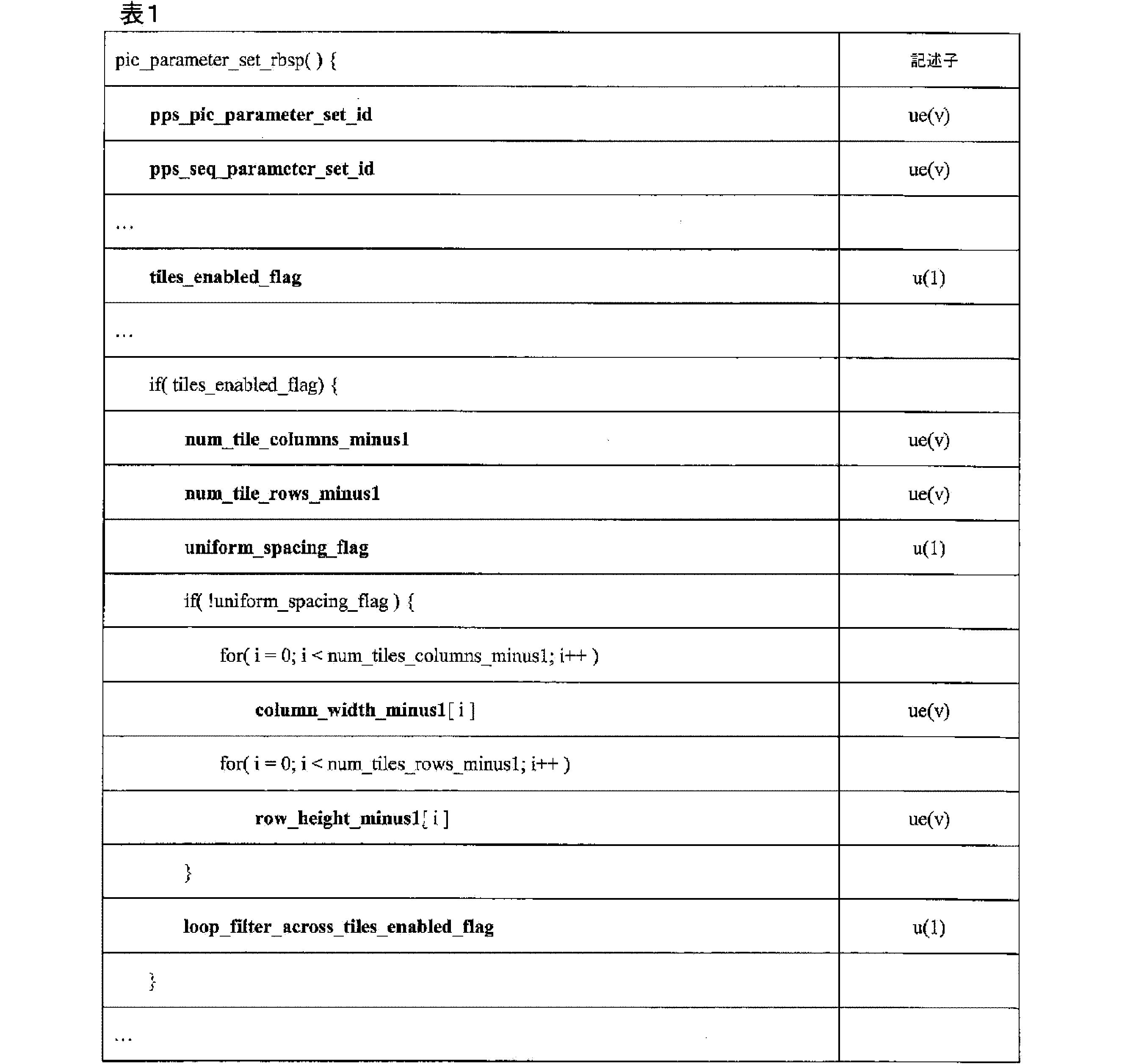
ITU-T H.265は、表1に示されたそれぞれのシンタックス要素に対して以下の定義を規定する。pps_pic_parameter_set_idは、他のシンタックス要素による参照のためのPPSを指定する。pps_pic_parameter_set_idの値は、両端値を含む、0~63の範囲にあるものとする。
ITU-T H.265 specifies the following definitions for each syntax element shown in Table 1. pps_pic_parameter_set_id specifies the PPS for reference by other syntax elements. The value of pps_pic_parameter_set_id shall be in the
pps_seq_parameter_set_idは、アクティブSPSについてのsps_seq_parameter_set_idの値を指定する。pps_seq_parameter_set_idの値は、両端値を含む、0~15の範囲にあるものとする。
pps_seq_parameter_set_id specifies the value of sps_seq_parameter_set_id for the active SPS. The value of pps_seq_parameter_set_id shall be in the
1に等しいtiles_enabled_flagは、PPSを参照して、各ピクチャに2つ以上のタイルが存在することを指定する。0に等しいtiles_enabled_flagは、PPSを参照して、各ピクチャに1つのタイルのみが存在することを指定する。CVS内でアクティブ化される全てのPPSについては、tiles_enabled_flagの値が同じであることが、ビットストリームの適合性の要件である。 tiles_enabled_flag equal to 1 specifies that there is more than one tile in each picture, referencing the PPS. tiles_enabled_flag equal to 0 specifies that there is only one tile in each picture, referencing the PPS. It is a bitstream conformance requirement that the value of tiles_enabled_flag be the same for all PPSs activated in the CVS.
num_tile_columns_minus1プラス1は、ピクチャを区画するタイル列の数を指定する。num_tile_columns_minus1は、両端値を含む、0~PicWidthInCtbsY-1の範囲にあるものとする。num_tile_columns_minus1の値が存在しない場合、num_tile_columns_minus1の値は0に等しいと推測される。 num_tile_columns_minus1 plus 1 specifies the number of tile columns that divide the picture. num_tile_columns_minus1 shall be in the range from 0 to PicWidthInCtbsY-1, inclusive. If no value for num_tile_columns_minus1 is present, the value of num_tile_columns_minus1 is inferred to be equal to 0.
num_tile_rows_minus1プラス1は、ピクチャを区画するタイル行の数を指定する。num_tile_rows minus1は、両端値を含む、0~PicHeightInCtbsY-1の範囲にあるものとする。num_tile_rows_minus1の値が存在しない場合、num_tile_rows_minus1の値は0に等しいと推測される。tiles_enabled_flagが1に等しい場合、num_tile_columns_minus1及びnum_tile_rows_minus1は、いずれも0に等しくないものとする。 num_tile_rows_minus1 plus 1 specifies the number of tile rows that divide the picture. num_tile_rows minus1 shall be in the range from 0 to PicHeightInCtbsY-1, inclusive. If there is no value for num_tile_rows_minus1, then the value of num_tile_rows_minus1 is inferred to be equal to 0. If tiles_enabled_flag is equal to 1, then neither num_tile_columns_minus1 nor num_tile_rows_minus1 shall be equal to 0.
1に等しいuniform_spacing_flagは、タイル列境界及び同様にタイルの行境界が、ピクチャにわたって均一に分布されることを指定する。0に等しいuniform_spacing_flagは、タイル列境界及び同様にタイルの行境界が、ピクチャにわたって均一に分布されないが、シンタックス要素column_width_minus1[i]及びrow_height_minus1[i]を使用して明示的にシグナリングされることを指定する。uniform_spacing_flagの値が存在しない場合、uniform_spacing_flagの値は1に等しいと推測される。 uniform_spacing_flag equal to 1 specifies that tile column borders, and similarly tile row borders, are uniformly distributed across the picture. uniform_spacing_flag equal to 0 specifies that tile column borders, and similarly tile row borders, are not uniformly distributed across the picture, but are explicitly signaled using the syntax elements column_width_minus1[i] and row_height_minus1[i]. If no value for uniform_spacing_flag is present, the value of uniform_spacing_flag is inferred to be equal to 1.
column_width_minus1[i]プラス1は、符号化ツリーブロックの単位におけるi番目のタイル列の幅を指定する。 column_width_minus1[i] plus 1 specifies the width of the i-th tile column in units of coding tree blocks.
row_height_minus1[i]プラス1は、符号化ツリーブロックの単位におけるi番目のタイル行の高さを指定する。 row_height_minus1[i] plus 1 specifies the height of the i-th tile row in units of coding tree blocks.
更に、ITU-T H.265では、ビットストリーム内のエントリポイントに関する情報は、スライスセグメントヘッダを使用してシグナリングされる。表2は、エントリポイントをシグナリングするための関連するシンタックス要素を含むITU-T H.265に指定されたスライスセグメントヘッダのシンタックスの一部である。 Furthermore, in ITU-T H.265, information about entry points in the bitstream is signaled using slice segment headers. Table 2 shows part of the syntax of the slice segment header specified in ITU-T H.265, including the relevant syntax elements for signaling entry points.

ITU-T H.265は、表2に示されたそれぞれのシンタックス要素に対して以下の定義を規定する。 ITU-T H.265 specifies the following definitions for each syntax element shown in Table 2.
slice_pic_parameter_set_idは、使用中のPPSのpps_pic_parameter_set_idの値を指定する。slice_pic_parameter_set_idの値は、両端値を含む、0~63の範囲にあるものとする。 slice_pic_parameter_set_id specifies the value of pps_pic_parameter_set_id for the PPS in use. The value of slice_pic_parameter_set_id shall be in the range of 0 to 63, inclusive.
num_entry_point_offsetsは、スライスヘッダ内のentry_point_offset_minus1[i]シンタックス要素の数を指定する。num_entry_point_offsetsの値が存在しない場合、num_entry_point_offsetsの値は0に等しいと推測される。 num_entry_point_offsets specifies the number of entry_point_offset_minus1[i] syntax elements in the slice header. If the value of num_entry_point_offsets is not present, the value of num_entry_point_offsets is inferred to be equal to 0.
num_entry_point_offsetの値は、以下のように制約される。 The value of num_entry_point_offset is constrained as follows:
-tiles_enabled_flagが0に等しく、entropy_coding_sync_enabled_flagが1に等しい場合、num_entry_point_offsetsの値は、両端値を含む、0~PicHeightInCtbsY-1の範囲であるものとする。 When -tiles_enabled_flag is equal to 0 and entropy_coding_sync_enabled_flag is equal to 1, the value of num_entry_point_offsets shall be in the range from 0 to PicHeightInCtbsY-1, inclusive.
-そうでなければ、tiles_enabled_flagが1に等しく、entropy_coding_sync_enabled_flagが0に等しい場合、num_entry_point_offsetsの値は、両端値を含む、0~(num_tile_columns_minus1+1)*(num_tile_rows_minus1+1)-1の範囲であるものとする。 - Otherwise, if tiles_enabled_flag is equal to 1 and entropy_coding_sync_enabled_flag is equal to 0, the value of num_entry_point_offsets shall be in the range from 0 to (num_tile_columns_minus1+1) * (num_tile_rows_minus1+1)-1, inclusive.
-そうでなければ、tiles_enabled_flagが1に等しく、entropy_coding_sync_enabled_flagが1に等しい場合、num_entry_point_offsetsの値は、両端値を含む、0~(num_tile_columns_minus1+1)*PicHeightInCtbsY-1の範囲であるものとする。 - Otherwise, if tiles_enabled_flag is equal to 1 and entropy_coding_sync_enabled_flag is equal to 1, the value of num_entry_point_offsets shall be in the range from 0 to (num_tile_columns_minus1+1) * PicHeightInCtbsY-1, inclusive.
offset_len_minus1プラス1は、entry_point_offset_minus1[i]シンタックス要素の長さ (ビット)を指定する。offset_len_minus1の値は、両端値を含む、0~31の範囲にあるもの
とする。
offset_len_minus1 plus 1 specifies the length (in bits) of the entry_point_offset_minus1[i] syntax element. The value of offset_len_minus1 shall be in the
entry_point_offset_minus1[i]プラス1は、i番目のエントリポイントオフセット(バイト)を指定し、offset_len_minus1プラス1ビットで表される。スライスセグメントデータは、スライスセグメントのヘッダに続き、num_entry_point_offset+1サブセットからなり、サブセットインデックス値は、両端値を含む0~num_entry_point_offsetの範囲である。スライスセグメントデータの第1のバイトは、バイト0と見なされる。存在する場合、符号化スライスセグメントNALユニットのスライスセグメントデータ部分に現れるエミュレーション防止バイトは、サブセット識別の目的でスライスセグメントデータの一部としてカウントされる。サブセット0は、符号化スライスセグメントデータのバイト0からentry_point_offset_minus1[0](両端値を含む)からなり、kが1~num_entry_point_offsets-1(両端値を含む)の範囲のkを有するサブセットkは、符号化スライスセグメントデータのバイトfirstByte[k]~lastByte[k](両端値を含む)からなり、firstByte[k]及びlastByte[k]は、以下のとおり定義される。
entry_point_offset_minus1[i] plus 1 specifies the i-th entry point offset (in bytes) and is represented by offset_len_minus1 plus 1 bits. The slice segment data follows the slice segment header and consists of num_entry_point_offset+1 subsets, with subset index values in the

最後のサブセット(num_entry_point_offsetに等しいサブセットインデックスを有する)は、符号化スライスセグメントデータのバイトからなる。 The final subset (with subset index equal to num_entry_point_offset) consists of bytes of encoded slice segment data.
tiles_enabled_flagが1に等しく、entropy_coding_sync_enabled_flagが0に等しい場合、各サブセットは、同じタイル内にあるスライスセグメント内の全ての符号化ツリーユニットの全ての符号化ビットからなり、サブセットの数(すなわち、num_entry_point_offsets+1の値)は、符号化スライスセグメントである符号化ツリーユニットを含むタイルの数に等しいものとする。 If tiles_enabled_flag is equal to 1 and entropy_coding_sync_enabled_flag is equal to 0, each subset consists of all the coded bits of all coding tree units in the slice segment in the same tile, and the number of subsets (i.e., the value of num_entry_point_offsets+1) is equal to the number of tiles that contain coding tree units that are coded slice segments.
注6-tiles_enabled_flagが1に等しく、entropy_coding_sync_enabled_flagが0に等しい場合、各スライスは、1つのタイルの符号化ツリーユニットのサブセット(この場合、シンタックス要素entry_point_offset_minus1[i]は存在しない)を含む必要があるか、又は完全なタイルの整数の全ての符号化ツリーユニットを含む必要がある。 NOTE 6 - If tiles_enabled_flag is equal to 1 and entropy_coding_sync_enabled_flag is equal to 0, then each slice must contain either a subset of the coding tree units of one tile (in this case the syntax element entry_point_offset_minus1[i] is not present) or all coding tree units of an integer number of complete tiles.
tiles_enabled_flagが0に等しく、entropy_coding_sync_enabled_flagが1に等しい場合、kが0~num_entry_point_offsets(両端値を含む)の範囲のkを有する各サブセットkは、ピクチャの同じルマ符号化ツリーブロック行内にあるルマ符号化ツリーブロックを含むスライスセグメント内の全ての符号化ツリーユニットの全ての符号化ビットからなり、サブセットの数(すなわち、num_entry_point_offsets+1の値)は、符号化スライスセグメント内にある符号化ツリーユニットを含むピクチャの符号化ツリーブロック行の数に等しいものとする。
When tiles_enabled_flag is equal to 0 and entropy_coding_sync_enabled_flag is equal to 1, each subset k, with k in the
注7-最後のサブセット(すなわち、num_entry_point_offsetsに等しいkのサブセットk)は、ピクチャのルマ符号化ツリーブロック行にあるルマ符号化ツリーブロックを含む全ての符号化ツリーユニットを含んでも含まなくてもよい。 NOTE 7 - The last subset (i.e., subset k with k equal to num_entry_point_offsets) may or may not include all coding tree units that contain luma coding tree blocks in the luma coding tree block row of the picture.
tiles_enabled_flagが1に等しく、entropy_coding_sync_enabled_flagが1に等しい場合、kが1~num_entry_point_offsets(両端値を含む)の範囲のkを有する各サブセットkは、タイルの同じルマ符号化ツリーブロック行内にあるルマ符号化ツリーブロックを含むスライスセグメント内の全ての符号化ツリーユニットの全ての符号化ビットからなり、サブセットの数(すなわち、num_entry_point_offsets+1の値)は、符号化スライスセグメント内にある符号化ツリーユニットを含むタイルのルマ符号化ツリーブロック行の数に等しいものとする。
When tiles_enabled_flag is equal to 1 and entropy_coding_sync_enabled_flag is equal to 1, each subset k, with k in the
上記のシンタックス及びセマンティックに示すように、ITU-T H.265では、タイル構造は多数の列及び数字の行によって指定され、したがって、各行及び列が同じ数のタイルを含むという点で制限される。このようにしてタイル構造を制限することは、理想的ではない場合がある。本明細書に記載される技術によれば、ビデオエンコーダは、増加した柔軟性を提供する様式でタイル構造及びタイルセットをシグナリングすることができる。 As shown in the syntax and semantics above, in ITU-T H.265, the tile structure is specified by a number of columns and rows of numbers, and is therefore restricted in that each row and column contains the same number of tiles. Restricting the tile structure in this manner may not be ideal. The techniques described herein enable a video encoder to signal the tile structure and tile sets in a manner that provides increased flexibility.
図1は、本開示の1つ以上の技術による、ビデオデータを符号化する(符号化及び/又は復号する)ように構成することができる、システムの例を示すブロック図である。システム100は、本開示の1つ以上の技術に従って、ビデオデータをカプセル化することができるシステムの例を表す。図1に示すように、システム100は、ソースデバイス102と、通信媒体110と、目的デバイス120と、を含む。図1に示す例では、ソースデバイス102は、ビデオデータを符号化し、符号化したビデオデータを通信媒体110に送信するように構成された、任意のデバイスを含むことができる。目的デバイス120は、通信媒体110を介して符号化したビデオデータを受信し、符号化したビデオデータを復号するように構成された、任意のデバイスを含むことができる。ソースデバイス102及び/又は目的デバイス120は、有線及び/又は無線通信用に装備された演算デバイスを含むことができ、かつ、例えば、セットトップボックス、デジタルビデオレコーダ、テレビ、デスクトップ、ラップトップ、又はタブレットコンピュータ、ゲーム機、医療用撮像デバイス、及び、例えば、スマートフォン、セルラー電話、パーソナルゲームデバイスを含むモバイルデバイス、を含むことができる。
FIG. 1 is a block diagram illustrating an example of a system that may be configured to encode (encode and/or decode) video data according to one or more techniques of the present disclosure. System 100 represents an example of a system that may encapsulate video data according to one or more techniques of the present disclosure. As shown in FIG. 1, system 100 includes a source device 102, a
通信媒体110は、無線及び有線の通信媒体並びに/又は記憶デバイスの任意の組み合わせを含むことができる。通信媒体110としては、同軸ケーブル、光ファイバケーブル、ツイストペアケーブル、無線送信機及び受信機、ルータ、スイッチ、リピータ、基地局、又は様々なデバイスとサイトとの間の通信を容易にするために有用であり得る任意の他の機器を挙げることができる。通信媒体110は、1つ以上のネットワークを含むことができる。例えば、通信媒体110は、ワールドワイドウェブ、例えば、インターネットへのアクセスを可能にするように構成されたネットワークを含むことができる。ネットワークは、1つ以上の電気通信プロトコルの組み合わせに従って動作することができる。電気通信プロトコルは、専用の態様を含むことができ、及び/又は規格化された電気通信プロトコルを含むことができる。標準化された電気通信プロトコルの例としては、Digital Video Broadcasting(DVB)規格、Advanced Television Systems Committee(ATSC)規格、Integrated Services Digital Broadcasting(ISDB)規格、Data Over Cable Service Interface Specification(DOCSIS)規格、Global System Mobile Communications(GSM)規格、符号分割多重アクセス(code division multiple access、CDMA)規格、第三世代パートナーシッププロジェクト(3rd Generation Partnership Project、3GPP)規格、欧州電気通信標準化機構(European Telecommunications Standards Institute、ETSI)規格、インターネットプロトコル(Internet Protocol、IP)規格、ワイヤレスアプリケーションプロトコル(Wireless Application Protocol、WAP)規格、及びInstitute of Electrical and Electronics Engineers(IEEE)規格が挙げられる。
The
記憶デバイスは、データを記憶することができる任意の種類のデバイス又は記憶媒体を含むことができる。記憶媒体は、有形又は非一時的コンピュータ可読媒体を含むことができる。コンピュータ可読媒体としては、光学ディスク、フラッシュメモリ、磁気メモリ、又は任意の他の好適なデジタル記憶媒体を挙げることができる。いくつかの例では、メモリデバイス又はその一部分は不揮発性メモリとして説明されることがあり、他の例では、メモリデバイスの一部分は揮発性メモリとして説明されることがある。揮発性メモリの例としては、ランダムアクセスメモリ(random access memory、RAM)、ダイナミックランダムアクセスメモリ(dynamic random access memory、DRAM)、及びスタティックランダムアクセスメモリ(static random access memory、SRAM)を挙げることができる。不揮発性メモリの例としては、磁気ハードディスク、光学ディスク、フロッピーディスク、フラッシュメモリ、又は電気的プログラム可能メモリ(electrically programmable memory、EPROM)若しくは電気的消去可能及びプログラム可能メモリ(electrically erasable and programmable、EEPROM)の形態を挙げることができる。記憶デバイス(単数又は複数)としては、メモリカード(例えば、セキュアデジタル(Secure Digital、SD)メモリカード)、内蔵/外付けハードディスクドライブ、及び/又は内蔵/外付けソリッドステートドライブを挙げることができる。データは、定義されたファイルフォーマットに従って記憶デバイス上に記憶することができる。 A storage device may include any type of device or storage medium capable of storing data. A storage medium may include a tangible or non-transitory computer-readable medium. A computer-readable medium may include an optical disk, a flash memory, a magnetic memory, or any other suitable digital storage medium. In some examples, a memory device or a portion thereof may be described as a non-volatile memory, and in other examples, a portion of a memory device may be described as a volatile memory. Examples of volatile memory may include random access memory (RAM), dynamic random access memory (DRAM), and static random access memory (SRAM). Examples of non-volatile memory may include a magnetic hard disk, an optical disk, a floppy disk, a flash memory, or a form of electrically programmable memory (EPROM) or electrically erasable and programmable memory (EEPROM). The storage device(s) may include memory cards (e.g., Secure Digital (SD) memory cards), internal/external hard disk drives, and/or internal/external solid state drives. Data may be stored on the storage device according to a defined file format.
図4は、システム100の一実装形態に含まれ得る構成要素の一例を示す概念的描画である。図4に示す例示的な実装形態では、システム100は、1つ以上の演算デバイス402A~402N、テレビサービスネットワーク404、テレビサービスプロバイダサイト406、ワイドエリアネットワーク408、ローカルエリアネットワーク410、及び1つ以上のコンテンツプロバイダサイト412A~412Nを含む。図4に示す実装形態は、例えば、映画、ライブスポーツイベントなどのデジタルメディアコンテンツ、並びにデータ及びアプリケーション及びそれらに関連付けられたメディアプレゼンテーションが、演算デバイス402A~402Nなどの複数の演算デバイスに配布され、かつ、それらによってアクセスされることが可能となるように構成され得るシステムの一例を表す。図4に示す例では、演算デバイス402A~402Nは、テレビサービスネットワーク404、ワイドエリアネットワーク408、及び/又はローカルエリアネットワーク410のうちの1つ以上からデータを受信するように構成されている任意のデバイスを含むことができる。例えば、演算デバイス402A~402Nは、有線及び/又は無線通信用に装備してもよく、1つ以上のデータチャネルを通じてサービスを受信するように構成してもよく、いわゆるスマートテレビ、セットトップボックス、及びデジタルビデオレコーダを含むテレビを含んでもよい。更に、演算デバイス402A~402Nは、デスクトップ、ラップトップ又はタブレットコンピュータ、ゲーム機、例えば「スマート」フォン、セルラー電話、及びパーソナルゲーミングデバイスを含むモバイルデバイスを含んでもよい。 FIG. 4 is a conceptual drawing illustrating an example of components that may be included in one implementation of the system 100. In the exemplary implementation shown in FIG. 4, the system 100 includes one or more computing devices 402A-402N, a television service network 404, a television service provider site 406, a wide area network 408, a local area network 410, and one or more content provider sites 412A-412N. The implementation shown in FIG. 4 represents an example of a system that may be configured to enable digital media content, such as movies, live sporting events, and data and applications and their associated media presentations, to be distributed to and accessed by multiple computing devices, such as the computing devices 402A-402N. In the example shown in FIG. 4, the computing devices 402A-402N may include any device configured to receive data from one or more of the television service network 404, the wide area network 408, and/or the local area network 410. For example, the computing devices 402A-402N may be equipped for wired and/or wireless communication and may be configured to receive services over one or more data channels, and may include televisions, including so-called smart televisions, set-top boxes, and digital video recorders. Additionally, the computing devices 402A-402N may include mobile devices, including desktop, laptop, or tablet computers, gaming consoles, e.g., "smart" phones, cellular phones, and personal gaming devices.
テレビサービスネットワーク404は、テレビサービスを含み得る、デジタルメディアコンテンツの配信を可能にするように構成されているネットワークの一例である。例えば、テレビサービスネットワーク404は、公共地上波テレビネットワーク、公共又は加入ベースの衛星テレビサービスプロバイダネットワーク、並びに公共又は加入ベースのケーブルテレビプロバイダネットワーク及び/又は頭越し型(over the top)サービスプロバイダ若しくはインターネットサービスプロバイダを含んでもよい。いくつかの実施例では、テレビサービスネットワーク404は、テレビサービスの提供を可能にするために主に使用され得るが、テレビサービスネットワーク404はまた、本明細書に記載された電気通信プロトコルの任意の組み合わせに基づく他の種類のデータ及びサービスの提供も可能とすることに留意されたい。更に、いくつかの実施例では、テレビサービスネットワーク404は、テレビサービスプロバイダサイト406と、演算デバイス402A~402Nのうちの1つ以上との間の双方向通信を可能にすることができることに留意されたい。テレビサービスネットワーク404は、無線通信メディア及び/又は有線通信メディアの任意の組み合わせを含むことができる。テレビサービスネットワーク404は、同軸ケーブル、光ファイバケーブル、ツイストペアケーブル、無線送信機及び受信機、ルータ、スイッチ、リピータ、基地局、又は様々なデバイスとサイトとの間の通信を容易にするために有用であり得る任意の他の機器を含むことができる。テレビサービスネットワーク404は、1つ以上の電気通信プロトコルの組み合わせに従って動作することができる。電気通信プロトコルは、専用の態様を含むことができ、及び/又は規格化された電気通信プロトコルを含むことができる。規格化された電気通信プロトコルの例としては、DVB規格、ATSC規格、ISDB規格、DTMB規格、DMB規格、ケーブルによるデータサービスインターフェース標準(Data Over Cable Service Interface Specification、DOCSIS)規格、HbbTV規格、W3C規格、及びUPnP規格が挙げられる。 The television service network 404 is an example of a network configured to enable the delivery of digital media content, which may include television services. For example, the television service network 404 may include a public terrestrial television network, a public or subscription-based satellite television service provider network, and a public or subscription-based cable television provider network and/or an over-the-top service provider or an Internet service provider. It should be noted that, in some embodiments, the television service network 404 may be primarily used to enable the provision of television services, but the television service network 404 may also enable the provision of other types of data and services based on any combination of telecommunication protocols described herein. Additionally, it should be noted that in some embodiments, the television service network 404 may enable bidirectional communication between the television service provider site 406 and one or more of the computing devices 402A-402N. The television service network 404 may include any combination of wireless communication media and/or wired communication media. The television service network 404 may include coaxial cables, fiber optic cables, twisted pair cables, wireless transmitters and receivers, routers, switches, repeaters, base stations, or any other equipment that may be useful for facilitating communication between various devices and sites. The television service network 404 may operate according to a combination of one or more telecommunications protocols. The telecommunications protocols may include proprietary aspects and/or standardized telecommunications protocols. Examples of standardized telecommunications protocols include the DVB standard, the ATSC standard, the ISDB standard, the DTMB standard, the DMB standard, the Data Over Cable Service Interface Specification (DOCSIS) standard, the HbbTV standard, the W3C standard, and the UPnP standard.
図4を再び参照すると、テレビサービスプロバイダサイト406は、テレビサービスネットワーク404を介してテレビサービスを配信するように構成することができる。例えば、テレビサービスプロバイダサイト406は、1つ以上の放送局、ケーブルテレビプロバイダ、又は衛星テレビプロバイダ、又はインターネットベースのテレビプロバイダを含み得る。例えば、テレビサービスプロバイダサイト406は、衛星アップリンク/ダウンリンクを介したテレビプログラムを含む送信を、受信するように構成することができる。更に、図4に示すように、テレビサービスプロバイダサイト406は、ワイドエリアネットワーク408と通信することができ、コンテンツプロバイダサイト412A~412Nからデータを受信するように構成することができる。いくつかの実施例では、テレビサービスプロバイダサイト406は、テレビスタジオを含むことができ、コンテンツはそこから発信できることに留意されたい。 Referring again to FIG. 4, the television service provider site 406 can be configured to distribute television services over the television service network 404. For example, the television service provider site 406 can include one or more broadcast stations, cable television providers, or satellite television providers, or Internet-based television providers. For example, the television service provider site 406 can be configured to receive transmissions including television programming over satellite uplinks/downlinks. Additionally, as shown in FIG. 4, the television service provider site 406 can be in communication with a wide area network 408 and can be configured to receive data from content provider sites 412A-412N. Note that in some implementations, the television service provider site 406 can include a television studio from which content can originate.
ワイドエリアネットワーク408は、パケットベースのネットワークを含み、1つ以上の電気通信プロトコルの組み合わせに従って動作することができる。電気通信プロトコルは、専用の態様を含むことができ、及び/又は規格化された電気通信プロトコルを含むことができる。規格化された電気通信プロトコルの例としては、汎欧州デジタル移動電話方式(Global System Mobile Communications、GSM)規格、符号分割多元接続(code division multiple access、CDMA)規格、3rd Generation Partnership Project(3GPP)規格、欧州電気通信標準化機構(European Telecommunications Standards Institute、ETSI)規格、欧州規格(EN)、IP規格、ワイヤレスアプリケーションプロトコル(Wireless Application Protocol、WAP)規格、及び例えば、IEEE802規格のうちの1つ以上(例えば、Wi-Fi)などの電気電子技術者協会(Institute of Electrical and Electronics Engineers、IEEE)規格が挙げられる。ワイドエリアネットワーク408は、無線通信メディア及び/又は有線通信メディアの任意の組み合わせを含むことができる。ワイドエリアネットワーク408は、同軸ケーブル、光ファイバケーブル、ツイストペアケーブル、イーサネットケーブル、無線送信部及び受信部、ルータ、スイッチ、リピータ、基地局、又は様々なデバイス及びサイト間の通信を容易にするために有用であり得る任意の他の機器を含むことができる。一実施例では、ワイドエリアネットワーク408はインターネットを含んでもよい。ローカルエリアネットワーク410は、パケットベースのネットワークを含み、1つ以上の電気通信プロトコルの組み合わせに従って動作することができる。ローカルエリアネットワーク410は、アクセス及び/又は物理インフラストラクチャのレベルに基づいてワイドエリアネットワーク408と区別することができる。例えば、ローカルエリアネットワーク410は、セキュアホームネットワークを含んでもよい。 The wide area network 408 may include a packet-based network and may operate according to a combination of one or more telecommunications protocols. The telecommunications protocols may include proprietary aspects and/or standardized telecommunications protocols. Examples of standardized telecommunications protocols include Global System Mobile Communications (GSM) standards, code division multiple access (CDMA) standards, 3rd Generation Partnership Project (3GPP) standards, European Telecommunications Standards Institute (ETSI) standards, European Standards (EN), IP standards, Wireless Application Protocol (WAP) standards, and Institute of Electrical and Electronics Engineers (IEEE) standards, such as, for example, one or more of the IEEE 802 standards (e.g., Wi-Fi). The wide area network 408 may include any combination of wireless communication media and/or wired communication media. Wide area network 408 may include coaxial cables, fiber optic cables, twisted pair cables, Ethernet cables, wireless transmitters and receivers, routers, switches, repeaters, base stations, or any other equipment that may be useful for facilitating communication between various devices and sites. In one embodiment, wide area network 408 may include the Internet. Local area network 410 may include packet-based networks and operate according to a combination of one or more telecommunications protocols. Local area network 410 may be distinguished from wide area network 408 based on level of access and/or physical infrastructure. For example, local area network 410 may include a secure home network.
図4を再び参照すると、コンテンツプロバイダサイト412A~412Nは、マルチメディアコンテンツをテレビサービスプロバイダサイト406及び/又は演算デバイス402A~402Nに提供することができるサイトの例を表す。例えば、コンテンツプロバイダサイトは、マルチメディアファイル及び/又はストリームをテレビサービスプロバイダサイト406に提供するように構成されている、1つ以上のスタジオコンテンツサーバを有するスタジオを含むことができる。一実施例では、コンテンツプロバイダのサイト412A~412Nは、IPスイートを使用してマルチメディアコンテンツを提供するように構成してもよい。例えば、コンテンツプロバイダサイトは、リアルタイムストリーミングプロトコル(RTSP)、HTTPなどに従って、マルチメディアコンテンツを受信デバイスに提供するように構成されてもよい。更に、コンテンツプロバイダサイト412A~412Nは、ハイパーテキストベースのコンテンツなどを含むデータを、ワイドエリアネットワーク408を通じて、受信デバイス、演算デバイス402A~402N、及び/又はテレビサービスプロバイダサイト406のうちの1つ以上に提供するように構成してもよい。コンテンツプロバイダサイト412A~412Nは、1つ以上のウェブサーバを含んでもよい。データプロバイダサイト412A~412Nによって提供されるデータは、データフォーマットに従って定義することができる。 Referring again to FIG. 4, the content provider sites 412A-412N represent examples of sites that may provide multimedia content to the television service provider site 406 and/or the computing devices 402A-402N. For example, the content provider sites may include a studio having one or more studio content servers configured to provide multimedia files and/or streams to the television service provider site 406. In one embodiment, the content provider sites 412A-412N may be configured to provide multimedia content using an IP suite. For example, the content provider sites may be configured to provide multimedia content to receiving devices according to the Real Time Streaming Protocol (RTSP), HTTP, or the like. Additionally, the content provider sites 412A-412N may be configured to provide data, including hypertext-based content, or the like, over the wide area network 408 to one or more of the receiving devices, the computing devices 402A-402N, and/or the television service provider site 406. The content provider sites 412A-412N may include one or more web servers. The data provided by the data provider sites 412A-412N can be defined according to a data format.
図1を再び参照すると、ソースデバイス102は、ビデオソース104と、ビデオエンコーダ106と、データカプセル化装置107と、インターフェース108とを含む。ビデオソース104は、ビデオデータをキャプチャ及び/又は記憶するように構成された任意のデバイスを含むことができる。例えば、ビデオソース104は、ビデオカメラ及びそれに動作可能に結合された記憶デバイスを含むことができる。ビデオエンコーダ106は、ビデオデータを受信し、ビデオデータを表す準拠ビットストリームを生成するように構成された、任意のデバイスを含むことができる。準拠ビットストリームは、ビデオデコーダが受信し、それからビデオデータを再生成することができるビットストリームを指すことがある。準拠ビットストリームの態様は、ビデオ符号化標準に従って定義することができる。準拠ビットストリームを生成するとき、ビデオエンコーダ106は、ビデオデータを圧縮することができる。圧縮は、非可逆的(視聴者に認識可能若しくは認識不可能)又は可逆的とすることができる。図5は、本明細書で説明するビデオデータを符号化するための技術を実施することができる、ビデオエンコーダ500の例を示すブロック図である。例のビデオエンコーダ500は、別個の機能ブロックを有するように示されているが、そのような例示は、説明のためのものであり、ビデオエンコーダ500及び/又はそのサブコンポーネントを特定のハードウェア又はソフトウェアアーキテクチャに限定するものではないことに留意されたい。ビデオエンコーダ500の機能は、ハードウェア、ファームウェア、及び/又はソフトウェアの実装形態の任意の組み合わせを用いて実現することができる。 Referring again to FIG. 1, source device 102 includes video source 104, video encoder 106, data encapsulator 107, and interface 108. Video source 104 may include any device configured to capture and/or store video data. For example, video source 104 may include a video camera and a storage device operably coupled thereto. Video encoder 106 may include any device configured to receive video data and generate a compliant bitstream representing the video data. A compliant bitstream may refer to a bitstream that a video decoder receives and from which the video data can be regenerated. Aspects of a compliant bitstream may be defined according to a video encoding standard. When generating a compliant bitstream, video encoder 106 may compress the video data. The compression may be lossy (perceptible or imperceptible to a viewer) or lossless. FIG. 5 is a block diagram illustrating an example of a video encoder 500 that may implement techniques for encoding video data described herein. It should be noted that while the example video encoder 500 is shown as having separate functional blocks, such illustration is for purposes of explanation and is not intended to limit the video encoder 500 and/or its subcomponents to any particular hardware or software architecture. The functionality of the video encoder 500 may be realized using any combination of hardware, firmware, and/or software implementations.
ビデオエンコーダ500は、ピクチャ領域のイントラ予測符号化及びインター予測符号化を実行する場合があり、そのためにハイブリッドビデオエンコーダと称される場合がある。図5に示す例では、ビデオエンコーダ500は、ソースビデオブロックを受信する。いくつかの例では、ソースビデオブロックは、符号化構造に従って分割されているピクチャの部分を含むことができる。例えば、ソースビデオデータは、マクロブロック、CTU、CB、その再分割、及び/又は別の同等の符号化ユニットを含むことができる。いくつかの例では、ビデオエンコーダ500は、ソースビデオブロックの追加の再分割を実行するように構成することができる。本明細書で説明する技術は、符号化の前及び/又は符号化中にソースビデオデータがどのように分割されるかにかかわらず、ビデオ符号化に一般的に適用可能であることに留意されたい。図5に示す例では、ビデオ符号化装置500は、加算部502と、変換係数発生装置504と、係数量子化部506と、逆量子化及び変換係数処理部508と、加算部510と、イントラ予測処理部512と、インター予測処理部514と、エントロピ符号化部516と、を含む。図5に示すように、ビデオエンコーダ500は、ソースビデオブロックを受信し、ビットストリームを出力する。 The video encoder 500 may perform intra-prediction and inter-prediction coding of picture regions, and may therefore be referred to as a hybrid video encoder. In the example shown in FIG. 5, the video encoder 500 receives a source video block. In some examples, the source video block may include a portion of a picture that is partitioned according to a coding structure. For example, the source video data may include a macroblock, a CTU, a CB, a subdivision thereof, and/or another equivalent coding unit. In some examples, the video encoder 500 may be configured to perform additional subdivision of the source video block. It should be noted that the techniques described herein are generally applicable to video coding, regardless of how the source video data is partitioned before and/or during the coding. In the example shown in FIG. 5, the video coding device 500 includes an adder 502, a transform coefficient generator 504, a coefficient quantizer 506, an inverse quantization and transform coefficient processor 508, an adder 510, an intra-prediction processor 512, an inter-prediction processor 514, and an entropy coder 516. As shown in FIG. 5, the video encoder 500 receives source video blocks and outputs a bitstream.
図5に示す例では、ビデオエンコーダ500は、ソースビデオブロックから予測ビデオブロックを減算することにより、残差データを生成することができる。予測ビデオブロックの選択を、以下に詳細に記載する。加算器502は、この減算演算を実行するように構成された構成要素を表す。一例では、ビデオブロックの減算は、画素領域で行われる。変換係数発生装置504は、離散コサイン変換(DCT)、離散サイン変換(DST)、又は概念的に類似の変換などの変換を残差ブロック又はその再分割に適用し(例えば、4つの8×8の変換を残差値の16×16のアレイに適用することができる)、残差変換係数のセットを生成する。変換係数発生装置504は、離散三角変換の近似物を含め離散三角変換のファミリーに含まれる変換の任意の及び全ての組み合わせを実行するように構成することができる。変換係数発生装置504は、変換係数を係数量子化部506に出力することができる。係数量子化部506は、変換係数の量子化を実行するように構成することができる。量子化プロセスは、係数の一部又は全てに関連付けられたビット深度を低減することができる。量子化の程度により、符号化したビデオデータのレートディストーション(すなわち、ビデオのビットレート対品質)が変更され得る。量子化の程度は、量子化パラメータ(QP)を調節することにより、修正することができる。量子化パラメータは、スライスレベル値及び/又はCUレベル値(例えば、CUデルタQP値)に基づいて判定することができる。QPデータは、特定の変換係数のセットを量子化するQPを判定するために使用される任意のデータを含み得る。図5に示すように、量子化された変換係数(レベル値と呼んでもよい)は、逆量子化及び変換係数処理部508に出力される。逆量子化及び変換係数処理部508は、逆量子化及び逆変換を適用して、復元された残差データを生成するように構成することができる。図5に示すように、加算器510において、復元された残差データを、予測ビデオブロックに加算することができる。このようにして、符号化ビデオブロックを復元することができ、結果として得られる復元されたビデオブロックを使用して、所与の予測、変換、及び/又は量子化についての符号化品質を評価することができる。ビデオ符号化装置500は、複数の符号化パスを実行する(例えば、予測、変換パラメータ及び量子化パラメータの1つ以上を変更しながら符号化を実行する)ように構成することができる。ビットストリームのレートディストーション又は他のシステムパラメータは、復元されたビデオブロックの評価に基づいて最適化することができる。更に、復元されたビデオブロックは、その後のブロックを予測するための参照として記憶して使用することができる。 In the example shown in FIG. 5, the video encoder 500 may generate the residual data by subtracting a predictive video block from a source video block. Selection of the predictive video block is described in more detail below. The adder 502 represents a component configured to perform this subtraction operation. In one example, the subtraction of the video blocks is performed in the pixel domain. The transform coefficient generator 504 applies a transform, such as a discrete cosine transform (DCT), a discrete sine transform (DST), or a conceptually similar transform, to the residual block or a subdivision thereof (e.g., four 8×8 transforms may be applied to a 16×16 array of residual values) to generate a set of residual transform coefficients. The transform coefficient generator 504 may be configured to perform any and all combinations of transforms included in the family of discrete triangular transforms, including approximations of the discrete triangular transform. The transform coefficient generator 504 may output the transform coefficients to a coefficient quantizer 506. The coefficient quantizer 506 may be configured to perform quantization of the transform coefficients. The quantization process may reduce the bit depth associated with some or all of the coefficients. The degree of quantization may change the rate distortion (i.e., video bit rate vs. quality) of the coded video data. The degree of quantization may be modified by adjusting a quantization parameter (QP). The quantization parameter may be determined based on slice level values and/or CU level values (e.g., CU delta QP value). The QP data may include any data used to determine a QP for quantizing a particular set of transform coefficients. As shown in FIG. 5, the quantized transform coefficients (which may also be referred to as level values) are output to an inverse quantization and transform coefficient processing unit 508. The inverse quantization and transform coefficient processing unit 508 may be configured to apply inverse quantization and inverse transform to generate reconstructed residual data. As shown in FIG. 5, the reconstructed residual data may be added to a prediction video block at an adder 510. In this manner, the coded video block may be reconstructed, and the resulting reconstructed video block may be used to evaluate the encoding quality for a given prediction, transform, and/or quantization. The video encoding device 500 may be configured to perform multiple encoding passes (e.g., performing encoding while varying one or more of prediction, transformation parameters, and quantization parameters). The rate distortion or other system parameters of the bitstream may be optimized based on evaluation of the reconstructed video blocks. Additionally, the reconstructed video blocks may be stored and used as references for predicting subsequent blocks.
図5を参照すると、イントラ予測処理部512は、符号化されるビデオブロックに対してイントラ予測モードを選択するように構成することができる。イントラ予測処理部512は、現在のブロックを符号化するために、フレームを評価し、使用するイントラ予測モードを判定するように構成することができる。上述したように、可能なイントラ予測モードは、平面予測モード、DC予測モード、及び角度予測モードを含んでもよい。更に、いくつかの例では、クロマ成分に対する予測モードは、ルマ予測モードに対する予測モードから推測できることに留意されたい。イントラ予測処理部512は、1つ以上の符号化パスを実行した後にイントラ予測モードを選択してもよい。更に、一実施例では、イントラ予測処理部512は、レートディストーション解析に基づいて予測モードを選択してもよい。図5に示すように、イントラ予測処理部512は、イントラ予測データ(例えば、シンタックス要素)をエントロピ符号化部516及び変換係数発生装置504に出力する。上述のように、残差データに対して実行される変換は、モード依存性であってもよい(例えば、二次変換行列は、予測モードに基づいて判定することができる)。 Referring to FIG. 5, the intra-predictor 512 may be configured to select an intra-prediction mode for the video block to be coded. The intra-predictor 512 may be configured to evaluate a frame and determine an intra-prediction mode to use to code a current block. As described above, possible intra-prediction modes may include a planar prediction mode, a DC prediction mode, and an angular prediction mode. Additionally, it should be noted that in some examples, the prediction mode for the chroma components may be inferred from the prediction mode for the luma prediction mode. The intra-predictor 512 may select the intra-prediction mode after performing one or more coding passes. Additionally, in one embodiment, the intra-predictor 512 may select the prediction mode based on a rate-distortion analysis. As shown in FIG. 5, the intra-predictor 512 outputs intra-prediction data (e.g., syntax elements) to the entropy encoder 516 and the transform coefficient generator 504. As described above, the transform performed on the residual data may be mode-dependent (e.g., a secondary transform matrix may be determined based on the prediction mode).
図5を再び参照すると、インター予測処理部514は、現在のビデオブロックに対してインター予測符号化を実行するように構成することができる。インター予測処理部514は、ソースビデオブロックを受信し、ビデオブロックのPUに対する動きベクトルを計算するように構成することができる。動きベクトルは、参照フレーム内の予測ブロックに対する、現在のビデオフレーム内のビデオブロックのPUの変位を示すことができる。インター予測符号化は、1つ以上の参照ピクチャを使用することができる。更に、動き予測は、単一予測(1つの動きベクトルを用いる)又は双予測(2つの動きベクトルを用いる)とすることができる。インター予測処理部514は、例えば、絶対差分和(sum of absolute difference)(SAD)、差分二乗和(sum of square difference)(SSD)、又は他の差の測定法によって判定された画素差を算出することにより、予測ブロックを選択するように構成することができる。上述したように、動きベクトルは、動きベクトル予測に従って判定及び判定することができる。インター予測処理部514は、上述したように、動きベクトル予測を実行するように構成することができる。インター予測処理部514は、動き予測データを用いて予測ブロックを生成するように構成することができる。例えば、インター予測処理部514は、フレームバッファ(図5に示さない)内に予測ビデオブロックを配置することができる。インター予測処理部514は、復元された残差ブロックに1つ以上の補間フィルタを適用して、動き予測に使用するための整数未満の画素値を算出するように更に構成することができることに留意されたい。インター予測処理部514は、計算された動きベクトルに対する動き予測データをエントロピ符号化部516に出力することができる。 Referring again to FIG. 5, the inter prediction processor 514 may be configured to perform inter prediction coding on the current video block. The inter prediction processor 514 may be configured to receive a source video block and calculate a motion vector for the PU of the video block. The motion vector may indicate a displacement of the PU of the video block in the current video frame relative to a prediction block in the reference frame. The inter prediction coding may use one or more reference pictures. Furthermore, the motion prediction may be uni-predictive (using one motion vector) or bi-predictive (using two motion vectors). The inter prediction processor 514 may be configured to select a prediction block by calculating pixel differences, determined by, for example, sum of absolute difference (SAD), sum of square difference (SSD), or other difference measures. As described above, a motion vector may be determined and determined according to the motion vector prediction. The inter prediction processor 514 may be configured to perform motion vector prediction, as described above. The inter prediction processor 514 may be configured to generate a prediction block using the motion prediction data. For example, the inter prediction processor 514 may place the prediction video block in a frame buffer (not shown in FIG. 5). Note that the inter prediction processor 514 may be further configured to apply one or more interpolation filters to the reconstructed residual block to calculate sub-integer pixel values for use in motion prediction. The inter prediction processor 514 may output motion prediction data for the calculated motion vectors to the entropy encoder 516.
図5を再び参照すると、エントロピ符号化部518は、量子化された変換係数及び予測シンタックスデータ(すなわち、イントラ予測データ、動き予測データ)を受信する。いくつかの例では、係数量子化部506は、係数がエントロピ符号化部518に出力される前に、量子化された変換係数を含む行列の走査を実行することができることに留意されたい。他の例では、エントロピ符号化部518は、走査を実行することができる。エントロピ符号化部518は、本明細書で説明する技術の1つ以上に従ってエントロピ符号化を実行するように構成することができる。このように、ビデオ符号化装置500は、本開示の1つ以上の技術に従って符号化ビデオデータを生成するように構成されているデバイスの一例を表す。一実施例では、ビデオ符号化器500は、動き制約タイルセットを含む符号化ビデオデータを生成することができる。 Referring again to FIG. 5, the entropy encoder 518 receives the quantized transform coefficients and prediction syntax data (i.e., intra prediction data, motion prediction data). Note that in some examples, the coefficient quantizer 506 may perform a scan of a matrix including the quantized transform coefficients before the coefficients are output to the entropy encoder 518. In other examples, the entropy encoder 518 may perform the scan. The entropy encoder 518 may be configured to perform entropy encoding according to one or more of the techniques described herein. Thus, the video encoder 500 represents an example of a device configured to generate encoded video data according to one or more techniques of this disclosure. In one example, the video encoder 500 may generate encoded video data including a motion constraint tile set.
図1を再び参照すると、データカプセル化部107は、符号化ビデオデータを受信し、定義されたデータ構造に従って準拠ビットストリーム、例えば、一連のNALユニットなどの準拠ビットストリームを生成することができる。準拠ビットストリームを受信するデバイスは、そこからビデオデータを再生成することができる。更に、上述のように、サブビットストリーム抽出とは、受信ビットストリーム内のデータを破棄及び/又は修正することによって、ITU-T H.265準拠ビットストリームを受信しているデバイスが、新たなITU-T H.265準拠ビットストリームを形成するプロセスを指し得る。適合ビットストリームという用語は、準拠ビットストリームという用語の代わりに使用され得ることに留意されたい。 Referring again to FIG. 1, the data encapsulator 107 may receive the encoded video data and generate a compliant bitstream, e.g., a series of NAL units, according to a defined data structure. A device receiving the compliant bitstream may regenerate the video data therefrom. Furthermore, as described above, sub-bitstream extraction may refer to a process in which a device receiving an ITU-T H.265 compliant bitstream forms a new ITU-T H.265 compliant bitstream by discarding and/or modifying data in the received bitstream. Note that the term conforming bitstream may be used instead of the term compliant bitstream.
上述したように、ITU-T H.265では、タイル構造は、各行及び列が同じ数のタイルを含むという点で制限される。いくつかの場合では、行及び/又は列において様々な数のタイルを有することが有用であり得る。例えば、360°の球状ビデオを符号化するためには、球の赤道よりも極領域でタイルを少なくすることが有用であり得、この場合、これは、行から行までタイル列の数を変化させるのに有用であり得る。一実施例では、データカプセル化装置107は、本明細書に記載される1つ以上の技術に従ってタイル構造をシグナリングするように構成することができる。データカプセル化装置107は、ビデオエンコーダ106と同じ物理デバイス内に配置される必要はないことに留意されたい。例えば、ビデオエンコーダ106及びデータカプセル化部107によって実行されるものとして説明される機能は、図4に示すデバイス間で配布してもよい。 As mentioned above, in ITU-T H.265, the tile structure is restricted in that each row and column contains the same number of tiles. In some cases, it may be useful to have a varying number of tiles in the rows and/or columns. For example, to encode 360° spherical video, it may be useful to have fewer tiles in the polar regions than at the equator of the sphere, in which case it may be useful to vary the number of tile columns from row to row. In one embodiment, the data encapsulator 107 may be configured to signal the tile structure according to one or more techniques described herein. It should be noted that the data encapsulator 107 need not be located in the same physical device as the video encoder 106. For example, the functions described as being performed by the video encoder 106 and the data encapsulator 107 may be distributed among the devices shown in FIG. 4.
本明細書に記載される技術によれば、データカプセル化装置107は、タイルセット構造のための以下の種類の情報のうちの1つ以上をシグナリングするように構成され得る。 In accordance with the techniques described herein, the data encapsulator 107 may be configured to signal one or more of the following types of information for the tile set structure:
タイルセットが有効であるかどうかを示すフラグ。有効でない場合、ピクチャ全体は、1つのタイルセットであると推測される。 A flag indicating whether tilesets are enabled. If not enabled, the whole picture is assumed to be one tileset.
タイルセットシグナリングが有効化された場合、以下をシグナリングすることができる。 When tileset signaling is enabled, the following can be signaled:
タイルセットの行の数は、シグナリングされてもよく、
タイルセットの列の数は、シグナリングされてもよい。
The number of rows in the tile set may be signaled;
The number of columns in a tile set may be signaled.
各タイルセットにおいて、以下の情報をシグナリングすることができる。 For each tile set, the following information can be signaled:
タイルセット内のタイル行の数、
タイルセット内のタイル列の数、
タイルがタイルセット内で行方向に沿って均一に離間されている場合にシグナリングするインジケータ/フラグ、及び/又は
タイルがタイルセット内で列方向に沿って均一に離間されている場合にシグナリングするインジケータ/フラグ、及び/又は
間隔が均一である場合、タイルセット毎に以下をシグナリングすることができる。
The number of tile rows in the tileset,
The number of tile columns in the tileset,
An indicator/flag signalling if tiles are evenly spaced row-wise within a tile set, and/or an indicator/flag signalling if tiles are evenly spaced column-wise within a tile set, and/or if the spacing is uniform, the following can be signalled for each tile set:
タイルセット内の各タイル行内のCTBの数のタイル幅、
タイルセット内の各タイル列内のCTBの数のタイル高さ、
間隔が均一でない場合、各タイルセット内のタイル毎に以下をシグナリングすることができる。
Tile width, the number of CTBs in each tile row in the tile set;
The tile height of the number of CTBs in each tile column in the tile set,
If the spacing is not uniform, the following can be signaled for each tile in each tile set:
タイルセット内の各タイル内の行のCTBの数、
タイルセット内の各タイル内の列のCTBの数
表3は、本明細書の技術によるタイル構造を信号化するために使用され得るパラメータセットのシンタックスの例を示す。一実施例では、表3に含まれる例示的なシンタックスは、PPSに含まれてもよい。他の例では、表3に含まれる例示的なシンタックスは、VPS又はSPSに含まれてもよい。
The number of CTBs in a row in each tile in the tileset,
The number of CTBs for a column in each tile in a tile set. Table 3 shows an example of a parameter set syntax that may be used to signal a tile structure in accordance with the techniques herein. In one embodiment, the example syntax included in Table 3 may be included in a PPS. In other examples, the example syntax included in Table 3 may be included in a VPS or SPS.

表3に関して、シンタックス要素tiles_enabled_flag、tilesets_enabled_flag、num_tile_columns_minus1[k][l]、num_tile_rows_minus1[k][l]、uniform_spacing_flag[k][1]、column_width_minus1[k][l][i]、row_height_minus1[k][l][i]、tile_width_m_ctbsy_minus1[k][l]、tile_height_in_ctbsy_minus1[k][l]、及びloop_filter_across_tiles_enabled_flag[k][l]は、以下の例示的な定義に基づくことができることに留意されたい。 With respect to Table 3, it is noted that the syntax elements tiles_enabled_flag, tilesets_enabled_flag, num_tile_columns_minus1[k][l], num_tile_rows_minus1[k][l], uniform_spacing_flag[k][1], column_width_minus1[k][l][i], row_height_minus1[k][l][i], tile_width_m_ctbsy_minus1[k][l], tile_height_in_ctbsy_minus1[k][l], and loop_filter_across_tiles_enabled_flag[k][l] may be based on the following exemplary definitions:
1に等しいtiles_enabled_flagは、パラメータセットを参照して、各ピクチャ内に2つ以上のタイルが存在することを指定する。0に等しいtiles_enabled_flagは、パラメータセットを参照して、各ピクチャ内に1つのタイルのみが存在することを指定する。 A tiles_enabled_flag equal to 1 specifies that there is more than one tile in each picture, as referenced by the parameter set. A tiles_enabled_flag equal to 0 specifies that there is only one tile in each picture, as referenced by the parameter set.
1に等しいtilesets_enabled_flagは、パラメータセットを参照して、各ピクチャ内に2つ以上のタイルセットが存在することを指定する。0に等しいtilesets_enabled_flagは、パラメータセットを参照して、各ピクチャ内に1つのタイルセットのみが存在することを指定する。 A tileset_enabled_flag equal to 1 specifies that there may be more than one tileset in each picture, referencing the parameter set. A tileset_enabled_flag equal to 0 specifies that there may be only one tileset in each picture, referencing the parameter set.
CVS内でアクティブ化される全てのパラメータセットについては、tilesets_enabled_flagの値が同じであることが、ビットストリームの適合性の要件である。 It is a requirement of bitstream conformance that all parameter sets activated in CVS have the same value for tilesets_enabled_flag.
tiles_enabled_flagが0に等しい場合、tilesets_enabled_flagが0に等しいことがビットストリームの適合性の要件である。 If tiles_enabled_flag is equal to 0, it is a requirement of bitstream conformance that tilesets_enabled_flag is equal to 0.
num_tile_set_columns_minus1プラス1は、ピクチャを区画するタイル列の数を指定する。num_tile_set_columns_minus1は、両端値を含む、0~PicWidthInCtbsY-1の範囲にあるものとする。num_tile_set_columns_minus1の値が存在しない場合、num_tile_set_columns_minus1の値は0に等しいと推測される。
num_tile_set_columns_minus1 plus 1 specifies the number of tile columns that divide the picture. num_tile_set_columns_minus1 shall be in the
num_tile_set_rows_minus1プラス1は、ピクチャを区画するタイル行の数を指定する。num_tile_set_rows_minus1は、両端値を含む、0~PicHeightInCtbsY-1の範囲にあるものとする。num_tile_set_rows_minus1の値が存在しない場合、num_tile_set_rows_minus1の値は0に等しいと推測される。 num_tile_set_rows_minus1 plus 1 specifies the number of tile rows that divide the picture. num_tile_set_rows_minus1 shall be in the range from 0 to PicHeightInCtbsY-1, inclusive. If a value for num_tile_set_rows_minus1 is not present, the value of num_tile_set_rows_minus1 is inferred to be equal to 0.
一実施例では、tilesets_enabled_flagが1に等しい場合、num_tile_set_columns_minus1及びnum_tile_set_rows_minus1は、いずれも0に等しくないものとする。 In one embodiment, if tilesets_enabled_flag is equal to 1, then neither num_tile_set_columns_minus1 nor num_tile_set_rows_minus1 is equal to 0.
num_tile_columns_minus1[k][1]プラス1は、インデックス(k,l)に関連付けられたタイルセットを区画するタイル列の数を指定する。num_tile_columns_minus1[k][1]は、両端値を含む、0~PicWidthInCtbsY-1の範囲にあるものとする。num_tile_columns_minus1[k]
[1]の値が存在しない場合、num_tile_columns_minus1[k][1]の値は0に等しいと推測される。
num_tile_columns_minus1[k][1] plus 1 specifies the number of tile columns that partition the tileset associated with index (k,l). num_tile_columns_minus1[k][1] must be in the
If the value of [1] is not present, the value of num_tile_columns_minus1[k][1] is inferred to be equal to 0.
別の例では、num_tile_columns_minus1[k][1]は、両端値を含む0~PicWidthInCtbsY-num_tile_set_columns_minus1-1の範囲にあるものとする。
In another example, num_tile_columns_minus1[k][1] is in the
num_tile_rows_minus1[k][1]プラス1は、インデックス(k,l)に関連付けられたタイルセットを区画するタイル行の数を指定する。num_tile_rows_minus1[k][1]は、両端値を含む、0~PicHeightlnCtbsY-1の範囲にあるものとする。num_tile_rows_minus1[k][1]の値が存在しない場合、num_tile_rows_minus1[k][1]の値は0に等しいと推測される。 num_tile_rows_minus1[k][1] plus 1 specifies the number of tile rows that partition the tileset associated with index (k,l). num_tile_rows_minus1[k][1] shall be in the range from 0 to PicHeightlnCtbsY-1, inclusive. If a value for num_tile_rows_minus1[k][1] is not present, the value of num_tile_rows_minus1[k][1] is inferred to be equal to 0.
別の例では、num_tile_rows_minus1[k][1]は、両端値を含む、0~PicHeightInCtbsY-num_tile_set_rows_minus1-1の範囲にあるものとする。
In another example, num_tile_rows_minus1[k][1] is in the
1に等しいuniform_spacing_flag[k][1]は、タイル列境界及び同様にタイルの行境界が、インデックス(k,l)に関連付けられたタイルセットにわたって均一に分布されることを指定する。0に等しいuniform_spacing_flag[k][1]は、タイル列境界及び同様にタイルの行境界が、インデックス(k,l)に関連付けられたタイルセットにわたって均一に分布されないが、シンタックス要素column_width_minus1[k][1][i]及びrow_height_minus1[k][1][
i]を使用して明示的にシグナリングされることを指定する。uniform_spacing_flag[k][1]の値が存在しない場合、uniform_spacing_flag[k][1]の値は1に等しいと推測される。
A uniform_spacing_flag[k][1] equal to 1 specifies that the tile column borders, and similarly the tile row borders, are uniformly distributed across the tile set associated with index (k,l). A uniform_spacing_flag[k][1] equal to 0 specifies that the tile column borders, and similarly the tile row borders, are not uniformly distributed across the tile set associated with index (k,l), but can be specified using the syntax elements column_width_minus1[k][1][i] and row_height_minus1[k][1][i].
i]. If no value for uniform_spacing_flag[k][1] is present, the value of uniform_spacing_flag[k][1] is inferred to be equal to 1.
column_width_minus1[i]プラス1は、インデックス(k,l)に関連付けられたタイルセットにおける符号化ツリーブロックの単位におけるi番目のタイル列の幅を指定する。 column_width_minus1[i] plus 1 specifies the width of the i-th tile column in units of coding tree blocks in the tile set associated with index (k,l).
row_height_minus1[k][1][i]プラス1は、インデックス(k,l)に関連付けられたタイルセット内の符号化ツリーブロックの単位におけるi番目のタイル行の高さを指定する。 row_height_minus1[k][1][i] plus 1 specifies the height of the i-th tile row in units of coding tree blocks in the tile set associated with index (k,l).
tile_width_in_ctbsy_minus1[k][1]プラス1は、符号化ツリーブロックの単位におけるインデックス(k,l)に関連付けられたタイルセット内の各タイル列の幅を指定する。 tile_width_in_ctbsy_minus1[k][1] plus 1 specifies the width of each tile column in the tile set associated with index (k,l) in units of coding tree blocks.
一実施例では、0~num_tile_set_rows_minus1の範囲の各kについて、0~num_tile_set_columns_minus1の範囲のlのtile_width_in_ctbsy_minus1[k][1]の合計の値が同じ値であることがビットストリームの適合性の要件である。
In one embodiment, a bitstream conformance requirement is that for each k in the
tile_height_in_ctbsy_minus1[k][1]プラス1は、符号化ツリーブロックの単位におけるインデックス(k,l)に関連付けられたタイルセット内の各タイル行の高さを指定する。 tile_height_in_ctbsy_minus1[k][1] plus 1 specifies the height of each tile row in the tile set associated with index (k,l) in units of coding tree blocks.
一実施例では、0~num_tile_ser_columns_minus1の範囲の各1について、0~num_tile_set_rowss_minus1の範囲のkのtile_height_in_ctbsy_minus1[k][1]の合計の値が同じ値であることがビットストリームの適合性の要件である。
In one embodiment, a bitstream conformance requirement is that for each 1 in the
1に等しいloop_filter_across_tiles_enabled_flag[k][l]は、インループフィルタリング操作が、PPSを参照して、インデックス(k,l)に関連付けられたタイルセット内のタイル境界を越えて実行され得ることを指定する。0に等しいloop_filter_across_tiles_enabled_flagは、インループフィルタリング操作が、PPSを参照して、インデックス(k,l)に関連付けられたタイルセット内のタイル境界を越えて実行されないことを指定する。インループフィルタリング操作は、デブロッキングフィルタ及びサンプル適応オフセットフィルタ操作を含む。loop_filter_across_tiles_enabled_flag[k][1]の値が存在しない場合、loop_filter_across_tiles_enabled_flag[k][1]の値は1に等しいと推測される。 loop_filter_across_tiles_enabled_flag[k][l] equal to 1 specifies that in-loop filtering operations may be performed across tile boundaries in the tile set associated with index (k,l) with reference to the PPS. loop_filter_across_tiles_enabled_flag equal to 0 specifies that in-loop filtering operations are not performed across tile boundaries in the tile set associated with index (k,l) with reference to the PPS. In-loop filtering operations include deblocking filter and sample adaptive offset filter operations. If a value for loop_filter_across_tiles_enabled_flag[k][1] is not present, a value of loop_filter_across_tiles_enabled_flag[k][1] equal to 1 is inferred.
別の例では、タイルセット行当たりの数タイルセット列は、タイルセット行毎に異なることが可能であり得る。表4は、本明細書の技術によるタイル構造を信号化するために使用され得るパラメータセットのシンタックスの例を示す。一実施例では、表4に含まれる例示的なシンタックスは、PPSに含まれてもよい。他の例では、表4に含まれる例示的なシンタックスは、VPS又はSPSに含まれてもよい。 In another example, the number tile set columns per tile set row may be allowed to vary from tile set row to tile set row. Table 4 shows an example of a parameter set syntax that may be used to signal a tile structure in accordance with the techniques herein. In one embodiment, the example syntax included in Table 4 may be included in a PPS. In other examples, the example syntax included in Table 4 may be included in a VPS or SPS.

表4に関して、シンタックス要素tiles_enabled_flag、tilesets_enabled_flag、num_tile_rows_minus1、uniform_spacing_flag[k][l]、column_width_minus1[k][l][i]、row_height_minus1[k][l][i]、tile_width_in_ctbsy_minus1[k][l]、tile_height_in_ctbsy_minus1[k][l]、及びloop_filter_across_tiles_enabled_flag[k][l]は、表3に関して上記に提供された定義に基づくことができることに留意されたい。num_tile_set_columns_minus1[k]は、以下の例示的な定義に基づくことができる。 Note that with respect to Table 4, the syntax elements tiles_enabled_flag, tilesets_enabled_flag, num_tile_rows_minus1, uniform_spacing_flag[k][l], column_width_minus1[k][l][i], row_height_minus1[k][l][i], tile_width_in_ctbsy_minus1[k][l], tile_height_in_ctbsy_minus1[k][l], and loop_filter_across_tiles_enabled_flag[k][l] may be based on the definitions provided above with respect to Table 3. num_tile_set_columns_minus1[k] may be based on the following example definition:
num_tile_set_columns_minus1[k]プラス1は、タイルセット行kにおけるタイルセット列の数を指定する。num_tile_set_columns_minus1[k]は、両端値を含む、0~PicWidthInCtbsY-1の範囲にあるものとする。num_tile_set_columns_minus1[k]の値が存在しない場合、num_tile_set_columns_minus1[k]の値は、両端値を含む、0~num_tile_set_rows_minus1の範囲のkについて、0に等しいと推測される。
num_tile_set_columns_minus1[k] plus 1 specifies the number of tileset columns in tileset row k. num_tile_set_columns_minus1[k] shall be in the
別の例では、タイルセット列当たりの数タイルセット行は、タイルセット行毎に異なることが可能であり得る。表5は、本明細書の技術によるタイル構造を信号化するために使用され得るパラメータセットのシンタックスの例を示す。一実施例では、表5に含まれる例示的なシンタックスは、PPSに含まれてもよい。他の例では、表5に含まれる例示的なシンタックスは、VPS又はSPSに含まれてもよい。 In another example, the number tile set rows per tile set column may be allowed to vary from tile set row to tile set row. Table 5 shows an example of a parameter set syntax that may be used to signal a tile structure in accordance with the techniques herein. In one embodiment, the example syntax included in Table 5 may be included in a PPS. In other examples, the example syntax included in Table 5 may be included in a VPS or SPS.
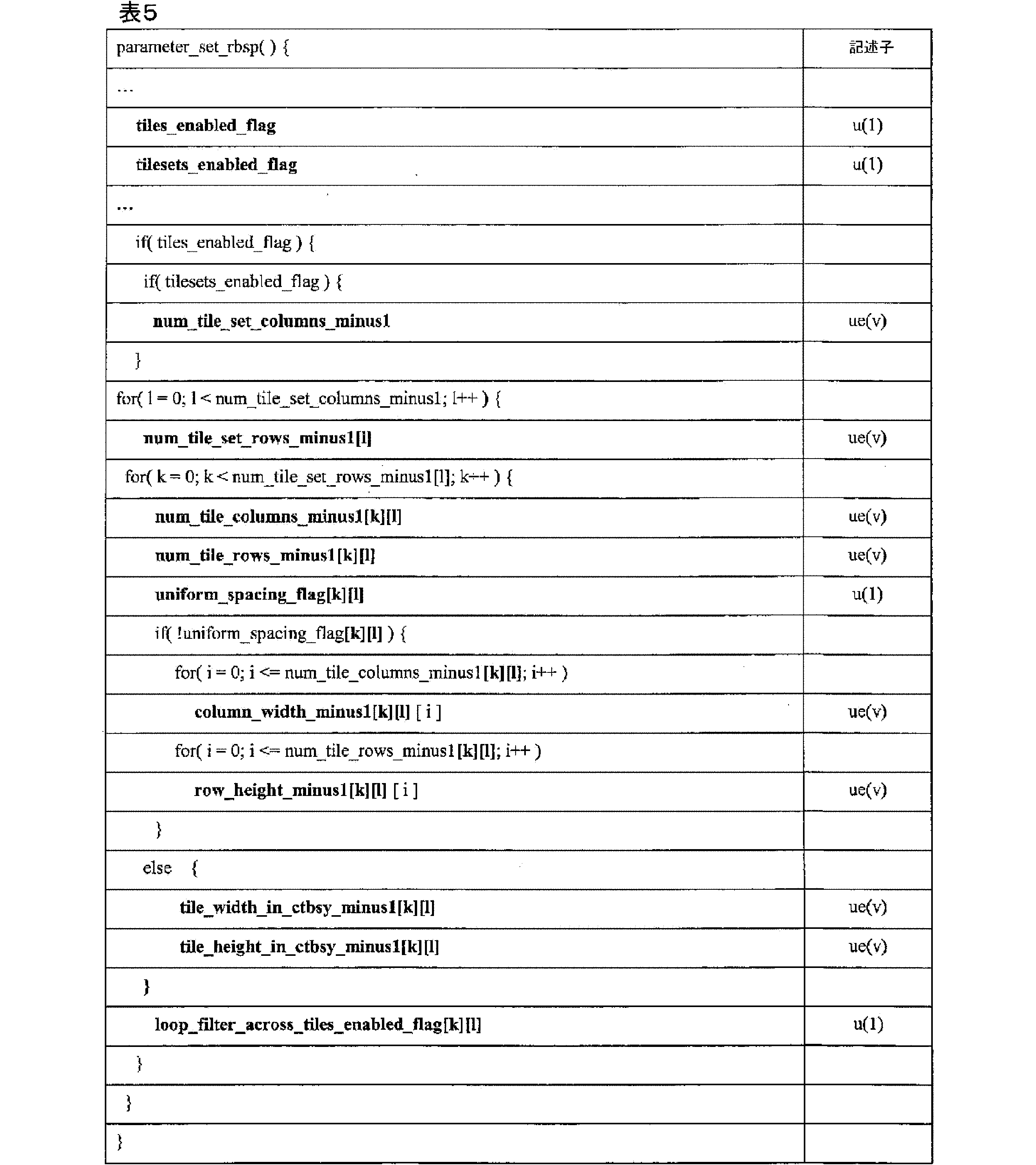
表5に関して、シンタックス要素tiles_enabled_flag、tilesets_enabled_flag、num_tile_columns_minus1、uniform_spacing_flag[k][l]、column_width_minus1[k][l][i]、row_height_minus1[k][l][i]、tile_width_in_cthsy_minus1[k][l]、tile_height_in_ctbsy_minus1[k][l]、及びloop_filter_across_tiles_enabled_flag[k][l]は、表3に関して上記に提供された定義に基づくことができることに留意されたい。num_tile_set_rows_minus1
[k]は、以下の例示的な定義に基づくことができる。
With respect to Table 5, it should be noted that the syntax elements tiles_enabled_flag, tilesets_enabled_flag, num_tile_columns_minus1, uniform_spacing_flag[k][l], column_width_minus1[k][l][i], row_height_minus1[k][l][i], tile_width_in_cthsy_minus1[k][l], tile_height_in_ctbsy_minus1[k][l], and loop_filter_across_tiles_enabled_flag[k][l] may be based on the definitions provided above with respect to Table 3.
[k] may be based on the following exemplary definition:
num_tile_set_rows_minus1[l]プラス1は、タイルセット列1におけるタイルセット行の数を指定する。num_tile_set_rows_minus1[l]は、両端値を含む、0~PicHeightlnCtbsY-1の範囲にあるものとする。num_tile_set_rows_minus1[k]の値が存在しない場合、num_tile_set_rows_minus1[1]の値は、両端値を含む、0~num_tile_set_columns_minus1の範囲のlについて、0に等しいと推測される。
num_tile_set_rows_minus1[l] plus 1 specifies the number of tileset rows in
この例に関して、別の例では、シンタックス要素num_tile_columns_mmusl[k][l]、num_tile_rows_minus1[k][l]、uniform_spacing_flag[k][l]、tile_width_in_ctbsy_minus1[k][l]、tile_height_in_ctbsy_minus1[k][l]、及びloop_filter_across_tiles_enabled_flag[k][l]についてのアレイインデックス[k][l]は、順序[l][k]のインデックスとして代わりにシグナリングされてもよく、そのため、シンタックス要素num_tile_columns_minus1[l][k]、num_tile_rows_minus1[l][k]、uniform_spacing_flag[l][k]、tile_width_in_ctbsy_minus1[l][k]、tile_height_in_ctbsy_minus1[l][k]、loop_filter_across_tiles_enabled_flag[l][k]としてシグナリングされてもよい。 For this example, in another example, the array index [k][l] for syntax elements num_tile_columns_mmusl[k][l], num_tile_rows_minus1[k][l], uniform_spacing_flag[k][l], tile_width_in_ctbsy_minus1[k][l], tile_height_in_ctbsy_minus1[k][l], and loop_filter_across_tiles_enabled_flag[k][l] is the order [l][k] of They may instead be signaled as indices and thus as syntax elements num_tile_columns_minus1[l][k], num_tile_rows_minus1[l][k], uniform_spacing_flag[l][k], tile_width_in_ctbsy_minus1[l][k], tile_height_in_ctbsy_minus1[l][k], loop_filter_across_tiles_enabled_flag[l][k].
更に、この例に関して、別の例では、要素column_width_minus1[k][l][i]、row_height_minus1[k][l][i]についてのアレイインデックス[k][l][i]は、順序[l][k][i]のインデックスとして代わりにシグナリングされてもよく、そのため、シンタックス要素column_width_minus1[l][k][i]、row_height_minus1[l][k][i]としてシグナリングされてもよい。 Further to this example, in another example, the array indexes [k][l][i] for elements column_width_minus1[k][l][i], row_height_minus1[k][l][i] may instead be signaled as indexes of order [l][k][i], and thus may be signaled as syntax elements column_width_minus1[l][k][i], row_height_minus1[l][k][i].
一実施例では、本明細書の技術によれば、タイルのラスタ順はタイルセット内で行ごとであってもよく、タイルセットは画像内でラスタ順序になる。これは、連続するタイルセット内の符号化データを形成し、タイルセットのビットストリームのスプライシング及びそれらのビットストリーム部分の並列復号を助けることができることに留意されたい。本明細書においてスプライシングという用語は、抽出された部分が1つ以上のタイルセットに対応し得る全体的なビットストリームの部分のみの抽出を指し得る。対照的に、ITU-T H.265では、タイルのラスタ順序は画像内で行ごとである。図6は、タイルのラスタ順はタイルセット内で行ごとであり、タイルセットは画像内でラスタ順序になるタイルラスタ走査を示す。図6では、各タイルに示される下付き文字数は、タイルがスキャナである順序を提供する。 In one embodiment, according to the techniques herein, the raster order of tiles may be row-by-row within a tile set, which are in raster order within the image. Note that this can make the encoded data in consecutive tile sets, aiding in splicing of the tile set bitstreams and parallel decoding of those bitstream portions. The term splicing as used herein may refer to the extraction of only a portion of the overall bitstream, where the extracted portion may correspond to one or more tile sets. In contrast, in ITU-T H.265, the raster order of tiles is row-by-row within an image. Figure 6 illustrates a tile raster scan where the raster order of tiles is row-by-row within a tile set, which are in raster order within the image. In Figure 6, the subscript numbers shown for each tile provide the order in which the tiles are in the scanner.
一実施例では、本明細書の技術によれば、符号化されたツリーブロック(CTB/CTU)のラスタ順序は、タイルセット内のタイルラスタ走査で行ごとであり得、タイルセットは、ピクチャ内でラスタ順序になる。これは、連続するタイルセット内の符号化データを形成し、タイルセットのビットストリームのスプライシング及び並列復号を助けることができることに留意されたい。本明細書においてスプライシングという用語は、抽出された部分が1つ以上のタイルセットに対応し得る全体的なビットストリームの部分のみの抽出を指し得る。対照的に、ITU-T H.265では、符号化されたツリーブロック(CTB/CTU)のラスタ順序は、ピクチャ内のタイルラスタ走査で行ごとである。図7は、符号化されたツリーブロック(CTB/CTU)のラスタ順序は、タイルセット内のタイルラスタ走査で行ごとであり得、タイルセットは、ピクチャ内でラスタ順序になることを示す。図7では、各CTUに示される数は、CTUがスキャンされる順序を提供する。図7の例は、図6に示すものと同じタイル構造を含むことに留意されたい。 In one embodiment, according to the techniques herein, the raster order of the coded tree blocks (CTB/CTU) may be row-by-row with tile raster scanning within a tile set, which is in raster order within a picture. Note that this may make the coded data within a contiguous tile set, which aids in splicing and parallel decoding of the tile set bit stream. The term splicing herein may refer to the extraction of only a portion of the overall bit stream, where the extracted portion may correspond to one or more tile sets. In contrast, in ITU-T H.265, the raster order of the coded tree blocks (CTB/CTU) is row-by-row with tile raster scanning within a picture. FIG. 7 shows that the raster order of the coded tree blocks (CTB/CTU) may be row-by-row with tile raster scanning within a tile set, which is in raster order within a picture. In FIG. 7, the numbers shown on each CTU provide the order in which the CTUs are scanned. Note that the example of FIG. 7 includes the same tile structure as shown in FIG. 6.
符号化されたツリーブロック(CTB/CTU)、タイル、及びタイルセットのラスタ順序は、以下の説明に基づいてもよい。 The raster order of coded treeblocks (CTB/CTU), tiles, and tile sets may be based on the following description:
このサブ項目は、VCL NALユニットの順序及び符号化されたピクチャへの関連を指定する。各VCL NALユニットは、符号化されたピクチャの一部である。 This subitem specifies the order of VCL NAL units and their association to a coded picture. Each VCL NAL unit is part of a coded picture.
符号化されたピクチャ内のVCL NALユニットの順序は、以下のように制約される。 The order of VCL NAL units within a coded picture is constrained as follows:
-符号化されたピクチャの第1のVCL NALユニットは、1に等しいfirst_slice_segment_in_pic_flagを有するものとする。 - The first VCL NAL unit of a coded picture shall have first_slice_segment_in_pic_flag equal to 1.
-sliceSegAddrA及びsliceSegAddrBは、同じ符号化ピクチャ内の任意の2つの符号化スライスセグメントNALユニットA及びBのslice_segment_address値である。以下の条件のいずれかが真である場合、符号化スライスセグメントNALユニットAは、符号化スライスセグメントNALユニットBに先行するものとする。 -sliceSegAddrA and sliceSegAddrB are the slice_segment_address values of any two coded slice segment NAL units A and B in the same coded picture. A coded slice segment NAL unit A precedes a coded slice segment NAL unit B if any of the following conditions are true:
-TileId[CtbAddrRsToTs[sliceSegAddrA]]は、TileId[CtbAddrRsToTs[sliceSegAddrB]]未満である。 -TileId[CtbAddrRsToTs[sliceSegAddrA]] is less than TileId[CtbAddrRsToTs[sliceSegAddrB]].
-TileId[CtbAddrRsToTs[sliceSegAddrA]]は、TileId[CtbAddrRsToTs[sliceSegAddrB]]に等しく、CtbAddrRsToTs[sliceSegAddrA]は、CtbAddrRsToTs[sliceSegAddrB]未満である。 -TileId[CtbAddrRsToTs[sliceSegAddrA]] is equal to TileId[CtbAddrRsToTs[sliceSegAddrB]] and CtbAddrRsToTs[sliceSegAddrA] is less than CtbAddrRsToTs[sliceSegAddrB].
CTBの単位で、インデックス(k,l)に関連付けられたタイルセットのi番目のタイル列の幅を指定する、両端値を含む、0~num_tile_set_rows_minus1の範囲のk、及び両端値を含む、0~num_tile_set_columns_minus1の範囲の1、両端値を含む、0~num_tile_columns_minus1の範囲のiについてのリストcolWidtht[k][l][i]は、以下のように導出される。
The list colWidtht[k][l][i], for k in the

CTBの単位で、インデックス(k,l)に関連付けられたタイルセットのj番目のタイル行の高さを指定する、両端値を含む、0~num_tile_set_rows_minus1の範囲のk、及び両端値を含む、0~num_tile_set_columns_minus1の範囲の1、両端値を含む、0~num_tile_rows_minus1の範囲のjについてのリストrowHeight[k][l][j]は、以下のように導出される。
The list rowHeight[k][l][j], for k in the

タイルセットの数を示す変数NumTileSetsは、以下のように導出される。 The variable NumTileSets, which indicates the number of tile sets, is derived as follows:

ルマCTBにおけるピクチャ幅、ルマCTBにおけるピクチャ高さ、及びインデックス(k,l)に関連付けられたタイルセットのルマCTBにおけるピクチャサイズをそれぞれ指定する、両端値を含む、0~num_tile_set_rows_minus1の範囲のk、及び両端値を含む、0~num_tile_set_columns_minus1の範囲の1についてのアレイpwctbsy[k][l]、phctbsy[k][l]、psizectbsy[k][l]、並びにインデックス(k,l)に関連付けられたタイルセットまでのCTBの累積カウントを指定する、両端値を含む、0~num_tile_set_rows_minus1の範囲のk、及び両端値を含む、0~num_tile_set_columns_minus1の範囲の1についてのアレイctbAddrRSOffset[k][l]は、以下のように導出される。
Arrays pwctbsy[k][l], phctbsy[k][l], psizectbsy[k][l] for k in the

j番目のタイルセットは、以下のようにインデックス(k,l)と関連付けられる。j番目のタイルセットは、インデックスjを有するタイルセットと呼ばれることがある。 The jth tileset is associated with index (k,l) as follows: The jth tileset is sometimes referred to as the tileset with index j.
タイルセットインデックスjを考慮すると、ピクチャのタイルセット列の数k及び1は、以下のように導出される。 Given a tile set index j, the number of tile set columns in a picture, k, and 1 are derived as follows:

インデックスk及びl並びにピクチャのタイルセット列の数を考慮すると、タイルセットインデックスjは、以下のように導出される。 Given the indexes k and l and the number of tile set columns in the picture, the tile set index j is derived as follows:

符号化ツリーブロックの単位で、インデックス(k,l)に関連付けられたタイルセットのi番目のタイル列境界の場所を指定する、両端値を含む、0~num_tile_set_rows_minus1の範囲のk、及び両端値を含む、0~num_tile_set_columns_minus1の範囲の1、両端値を含む、0~num_tile_columns_minus1+1の範囲のiについてのリストcolBd[k][l][i]は、以下のように導出される。
The list colBd[k][l][i], for k in the

符号化ツリーブロックの単位で、インデックス(k,l)に関連付けられたタイルセットのj番目のタイル行境界の場所を指定する、両端値を含む、0~num_tile_set_rows_minus1の範囲のk、及び両端値を含む、0~num_tile_set_columns_minus1の範囲の1、両端値を含む、0~num_tile_rows_minus1+1の範囲のjについてのリストrowBd[j]は、以下のように導出される。
The list rowBd[j], for k in the

ピクチャのCTBラスタ走査におけるCTBアドレスからタイルセット及びタイル走査におけるCTBアドレスへの変換を指定する、両端値を含む、0~PicSizelnCtbsY-1の範囲のctbAddrRsであるリストCtbAddrRsToTs[ctbAddrRs]は、以下のように導出される。
The list CtbAddrRsToTs[ctbAddrRs], which is a set of ctbAddrRs in the

タイル走査におけるCTBアドレスからピクチャのCTBラスタ走査におけるCTBアドレスへの変換を指定する、両端値を含む、0~PicSizeInCtbsY-1の範囲のctbAddrTsであるリストCtbAddrTsToRs[ctbAddrTs]は、以下のように導出される。
The list CtbAddrTsToRs[ctbAddrTs], which is a set of ctbAddrTs in the

タイル走査におけるCTBアドレスからタイルIDへの変換を指定する、両端値を含む、0~PicSizeInCtbsY-1の範囲のctbAddrTsであるリストTileId[ctbAddrTs]は、以下のように導出される。
The list TileId[ctbAddrTs], which is a set of ctbAddrTs in the

本明細書の技術による一実施例では、データカプセル化装置107は、タイルセット内の各タイルセット及びタイルが独立して処理され得るように情報をシグナリングするように構成され得る。一実施例では、各タイルセットのバイト範囲情報はシグナリングされる。一実施例では、これはタイルセットエントリポイントオフセットのリストとしてシグナリングされてもよい。図8は、それぞれ、T[j]及びT[j+1]のそれぞれが、それぞれ、j番目及び(j+1)番目のタイルセットに属するバイトのサイズをそれぞれ示す実施例を示す。加えて、タイルセット内のタイル毎に、各タイルセットバイト範囲情報がシグナリングされる。一実施例では、これはタイルエントリポイントオフセットのリストとしてシグナリングされてもよい。図8では、b[j][k]及びb[j+1][k]は、それぞれ、j番目のタイルセットのk番目のタイルサブセット及び(j+1)番目のタイルセットのk番目のタイルサブセットに属するバイトのサイズをそれぞれ示す。表6は、タイルセット内のタイルセット及びタイルのそれぞれが、本明細書の技術に従って独立して処理され得るように、情報をシグナリングするために使用され得る、例示的なスライスセグメントヘッダを示す。 In one embodiment according to the techniques herein, the data encapsulator 107 may be configured to signal information such that each tile set and tile within a tile set may be processed independently. In one embodiment, byte range information for each tile set is signaled. In one embodiment, this may be signaled as a list of tile set entry point offsets. FIG. 8 shows an example where T[j] and T[j+1] respectively indicate the size of bytes belonging to the jth and (j+1)th tile sets, respectively. Additionally, each tile set byte range information is signaled for each tile within a tile set. In one embodiment, this may be signaled as a list of tile entry point offsets. In FIG. 8, b[j][k] and b[j+1][k] respectively indicate the size of bytes belonging to the kth tile subset of the jth tile set and the kth tile subset of the (j+1)th tile set, respectively. Table 6 shows an example slice segment header that may be used to signal information so that each of the tile sets and tiles within a tile set may be processed independently in accordance with the techniques herein.

表6に関して、シンタックス要素tileset_ofiset_len_minus1、tileset_entry_point_offeet_minus1、num_entry_point_offsets、offset_len_minus1、及びentry_point_offset_minus1は、以下の定義に基づくことができることに留意されたい。 With respect to Table 6, note that the syntax elements tileset_ofiset_len_minus1, tileset_entry_point_offeet_minus1, num_entry_point_offsets, offset_len_minus1, and entry_point_offset_minus1 can be based on the following definitions:
tileset_offset_len_minus1プラス1は、tileset_entry_point_offset_minus1[i]シンタックス要素の長さ(ビット)を指定する。tileset_offset_len_minus1の値は、両端値を含む、0~31の範囲にあるものとする。
tileset_offset_len_minus1 plus 1 specifies the length (in bits) of the tileset_entry_point_offset_minus1[i] syntax element. The value of tileset_offset_len_minus1 shall be in the
tileset_entry_point_offset_minus1[i]プラス1は、i番目のタイルセットについてi番目のエントリポイントオフセット(バイト)を指定し、tileset_offset_len_minus1プラス1ビットで表される。スライスセグメントデータは、スライスセグメントのヘッダに続き、NumTileSetsサブセットからなり、タイルセットインデックス値は、両端値を含む、0~NumTileSets-1の範囲である。スライスセグメントデータの第1のバイトは、バイト0と見なされる。存在する場合、符号化スライスセグメントNALユニットのスライスセグメントデータ部分に現れるエミュレーション防止バイトは、サブセット識別の目的でスライスセグメントデータの一部としてカウントされる。タイルセット0は、符号化スライスセグメントデータのバイト0からtileset_entry_point_offset_minus1[0](両端値を含む)からなり、kが1~NumTileSets-1(両端値を含む)の範囲のkを有するタイルセットkは、符号化スライスセグメントデータのバイトfirstTilesetByte[k]~lastTileSetByte[k](両端値を含む)からなり、firstTileSetByte[k]及びlastTileSetByte[k]は、以下のとおり定義される。
tileset_entry_point_offset_minus1[i] plus 1 specifies the ith entry point offset (in bytes) for the ith tile set and is represented by tileset_offset_len_minus1 plus 1 bits. The slice segment data follows the slice segment header and consists of NumTileSets subsets, with tile set index values in the

最後のサブセット(サブセットインデックスがNumTileSetsに等しい)は、符号化スライスセグメントデータの残りのバイト、すなわち、lastTileSetByte[NumTileSets-l]+lからスライスセグメントデータの末尾までのバイトからなる。 The last subset (subset index equal to NumTileSets) consists of the remaining bytes of the coded slice segment data, i.e., bytes from lastTileSetByte[NumTileSets-l]+l to the end of the slice segment data.
各サブセットは、同じタイルセット内にあるスライスセグメント内の全ての符号化ツリーユニットの全ての符号化ビットからなるものとする。
num_entry_point_offsets[j]は、スライスヘッダ内のj番目のタイルセットのentry_point_offset_minus1[j][i]シンタックス要素の数を指定する。num_entry_point_offsets[j]の値が存在しない場合、num_entry_point_offsets[j]の値は0に等しいと推測される。
Each subset consists of all the coded bits of all the coding tree units in the slice segments that are in the same tile set.
num_entry_point_offsets[j] specifies the number of entry_point_offset_minus1[j][i] syntax elements for the jth tileset in the slice header. If the value of num_entry_point_offsets[j] is not present, the value of num_entry_point_offsets[j] is inferred to be equal to 0.
変数k及びlは、以下のように導出される。 The variables k and l are derived as follows:

num_entry_point_offset[j]の値は、以下のように制約される。 The value of num_entry_point_offset[j] is constrained as follows:
-tiles_enabled_flagが0に等しく、entropy_coding_sync_enabled_flagが1に等しい場合、num_entry point_offsets[j]の値は、両端値を含む、0~PicHeightInCtbsY-1の範囲であるものとする。
When -tiles_enabled_flag is equal to 0 and entropy_coding_sync_enabled_flag is equal to 1, the value of num_entry point_offsets[j] shall be in the
-そうでなければ、tiles_enabled_flagが1に等しく、entropy_coding_sync_enabled_flagが0に等しい場合、num_entry_point_offsets[j]の値は、両端値を含む、0~(num_tile_columns_minus1[k][l]+1)*(num_tile_rows_minus1[k][l]+1)-1の範囲であるものとする。 - Otherwise, if tiles_enabled_flag is equal to 1 and entropy_coding_sync_enabled_flag is equal to 0, the value of num_entry_point_offsets[j] shall be in the range from 0 to (num_tile_columns_minus1[k][l]+1) * (num_tile_rows_minus1[k][l]+1)-1, inclusive.
-そうでなければ、tiles_enabled_flagが1に等しく、entropy_coding_sync_enabled_flagが1に等しい場合、num_entry_point_offsetsの値は、両端値を含む、0~(num_tile_colunms_minus1[k][l]+1)*phctbsy[k][l]-1の範囲であるものとする。 - Otherwise, if tiles_enabled_flag is equal to 1 and entropy_coding_sync_enabled_flag is equal to 1, the value of num_entry_point_offsets shall be in the range from 0 to (num_tile_colunms_minus1[k][l]+1) * phctbsy[k][l]-1, inclusive.
offset_len_minus1[j]プラス1は、entry_point_offset_minus1[j][i]シンタックス要素の長さ(ビット)を指定する。offset_len_minus1[j]の値は、両端値を含む、0~31の範囲にあるものとする。
offset_len_minus1[j] plus 1 specifies the length (in bits) of the entry_point_offset_minus1[j][i] syntax element. The value of offset_len_minus1[j] shall be in the
entry_point_offset_minus1[i]プラス1は、j番目のタイルセットにおけるi番目のエントリポイントオフセット(バイト)を指定し、offset_len_minus1[j]1プラス1ビットで表される。j番目のタイルセットに対応するスライスセグメントデータ内のデータは、tileset_entry_point_offset_minus1[j]の位置に従い、num_entry_point_offsets[j]+1のサブセットからなり、j番目のタイルセットのサブセットインデックス値は、両端値を含む、0~num_entry_point_offsets[j]の範囲である。スライスセグメントデータの第1のバイトは、バイト0と見なされる。存在する場合、符号化スライスセグメントNALユニットのスライスセグメントデータ部分に現れるエミュレーション防止バイトは、サブセット識別の目的でスライスセグメントデータの一部としてカウントされる。j番目のタイルセットのサブセット0は、符号化スライスセグメントデータのバイトtileset_entry_point_offset_minus1[j]+0からtileset_entry_point_offset_minus1[j]+entry_point_offset_minus1[0](両端値を含む)からなり、kが1~num_entry_point_offsets[j]-1(両端値を含む)の範囲のkを有するサブセットkは、符号化スライスセグメントデータのバイトfirstByte[j][k]~lastByte[j][k](両端値を含む)からなり、firstByte[j][k]及びlastByte[j][k]は、以下のとおり定義される。
entry_point_offset_minus1[i] plus 1 specifies the ith entry point offset (in bytes) in the jth tile set and is represented by offset_len_minus1[j] plus 1 bits. The data in the slice segment data corresponding to the jth tile set consists of a subset of num_entry_point_offsets[j]+1 according to the position of tileset_entry_point_offset_minus1[j], where the subset index value for the jth tile set ranges from 0 to num_entry_point_offsets[j], inclusive. The first byte of slice segment data is considered to be

最後のサブセット(サブセットインデックスが[j][num_entry_point_offsets[j]]に等しい)は、バイトlastByte[j][num_entry_point_offsets[j]-1]+l~tileset_entry_point_offset_minus1[j+1]-1からなり、0~NumTileSets-1の範囲のjの符号化スライスセグメントデータの両端値を含む。
The last subset (subset index equal to [j][num_entry_point_offsets[j]]) consists of bytes lastByte[j][num_entry_point_offsets[j]-1]+l to tileset_entry_point_offset_minus1[j+1]-1, and includes both endpoints of the coded slice segment data for j in the
最後のタイルセットの最後のサブセット(サブセットインデックスが[NumTileSets-1][num_entry_point_offsets[NumTileSets]]に等しい)は、符号化スライスセグメントデータのバイト、すなわち、lastByte[NumTileSets-1][num_entry_point_offsets[j]-1]+lからスライスセグメントデータの末尾までのバイトからなる。 The last subset of the last tile set (subset index equal to [NumTileSets-1][num_entry_point_offsets[NumTileSets]]) consists of the bytes of coded slice segment data, i.e., the bytes from lastByte[NumTileSets-1][num_entry_point_offsets[j]-1]+l to the end of the slice segment data.
tiles_enabled_flagが1に等しく、entropy_coding_sync_enabled_flagが0に等しい場合、各サブセットは、同じタイル内にあるスライスセグメント内の全ての符号化ツリーユニットの全ての符号化ビットからなり、サブセットの数(すなわち、num_entry_point_offsets[j]+1の値)は、符号化スライスセグメント内のj番目のタイルセットにある符号化ツリーユニットを含むタイルの数に等しいものとする。 If tiles_enabled_flag is equal to 1 and entropy_coding_sync_enabled_flag is equal to 0, each subset consists of all the coded bits of all the coding tree units in the slice segment that are in the same tile, and the number of subsets (i.e., the value of num_entry_point_offsets[j]+1) is equal to the number of tiles that contain coding tree units in the jth tile set in the coding slice segment.
注記:tiles_enabled_flagが1に等しく、entropy_coding_sync_enabled_flagが0に等しい場合、各スライスは、1つのタイルの符号化ツリーユニットのサブセット(この場合、シンタックス要素entry_point_offset_minus1[j][i]は存在しない)を含む必要があるか、又は完全なタイルの整数の全ての符号化ツリーユニットを含む必要がある。 Note: If tiles_enabled_flag is equal to 1 and entropy_coding_sync_enabled_flag is equal to 0, then each slice must contain either a subset of the coding tree units of one tile (in this case the syntax element entry_point_offset_minus1[j][i] is not present) or all coding tree units of an integer number of complete tiles.
tiles_enabled_flagが0に等しく、entropy_coding_sync_enabled_flagが1に等しい場合、kが1~num_entry_point_offsets[j](両端値を含む)の範囲のkを有する各サブセットkは、ピクチャの同じルマ符号化ツリーブロック行内にあるルマ符号化ツリーブロックを含むスライスセグメント内の全ての符号化ツリーユニットの全ての符号化ビットからなり、サブセットの数(すなわち、num_entry_point_offsets[j]+1の値)は、符号化スライスセグメント内にある符号化ツリーユニットを含むピクチャの符号化ツリーブロック行の数に等しいものとする。
When tiles_enabled_flag is equal to 0 and entropy_coding_sync_enabled_flag is equal to 1, each subset k, with k in the
注記:最後のサブセット(すなわち、num entry point offsets[j]に等しいkのサブセットk)は、ピクチャのルマ符号化ツリーブロック行にあるルマ符号化ツリーブロックを含む全ての符号化ツリーユニットを含んでも含まなくてもよい。 Note: The last subset (i.e., the subset k of k equal to num entry point offsets[j]) may or may not include all coding tree units that contain luma coding tree blocks in the luma coding tree block row of the picture.
tiles_enabled_flagが1に等しく、entropy_coding_sync_enabled_flagが1に等しい場合、kが0~num_entry_point_offsets[j](両端値を含む)の範囲のkを有するj番目のタイルセットの各サブセットkは、j番目のタイルセット内のタイルの同じルマ符号化ツリーブロック行内にあるルマ符号化ツリーブロックを含むスライスセグメント内の全ての符号化ツリーユニットの全ての符号化ビットからなり、サブセットの数(すなわち、num_entry_point_offsets[j]+1の値)は、符号化スライスセグメント内にあるj番目のタイルセット内の符号化ツリーユニットを含むタイルのルマ符号化ツリーブロック行の数に等しいものとする。
When tiles_enabled_flag is equal to 1 and entropy_coding_sync_enabled_flag is equal to 1, each subset k of the jth tileset, with k in the
一実施例では、各タイルセット内のタイルのバイト範囲シグナリング(タイルオフセットシグナリング)の固定長符号化に使用されるオフセット長さ情報は、1回のみシグナリングされ得、全てのタイルセットに適用される。この例のシンタックスを表7に示す。 In one embodiment, the offset length information used for fixed length encoding of byte range signaling (tile offset signaling) of tiles within each tile set can be signaled only once and applies to all tile sets. The syntax for this example is shown in Table 7.

表7に関して、シンタックス要素tileset_offeet_len_minus1、tileset_entry_point_offset_minus1、num_entry_point_offsets、及びoffset_len_minus1は、表6に関して上記に提供された定義に基づくことができ、all_tile_offset_len_minus1及びentry_point_offset_minus1は、以下の定義に基づくことができることに留意されたい。 Note that with respect to Table 7, the syntax elements tileset_offeet_len_minus1, tileset_entry_point_offset_minus1, num_entry_point_offsets, and offset_len_minus1 may be based on the definitions provided above with respect to Table 6, and all_tile_offset_len_minus1 and entry_point_offset_minus1 may be based on the definitions below.
all_tile_offset_len_minus1プラス1は、両端値を含む、0~NumTileSets-1の範囲のjの各値についてentry_point_offset_minus1[j][i]シンタックス要素の長さ(ビット)を指定する。all_tile_offset_len_minus1の値は、両端値を含む、0~31の範囲にあるものとする。
all_tile_offset_len_minus1 plus 1 specifies the length (in bits) of the entry_point_offset_minus1[j][i] syntax element for each value of j in the
entry_point_offset_minus1[j][i]プラス1は、j番目のタイルセットについてi番目のエントリポイントオフセット(バイト)を指定し、all_tile_offset_len_minus1プラス1ビットで表される。 entry_point_offset_minus1[j][i] plus 1 specifies the i-th entry point offset (in bytes) for the j-th tile set, and is represented by all_tile_offset_len_minus1 plus 1 bits.
一実施例では、タイルバイト範囲情報は、ピクチャ内の全てのタイルについてループに関して単一にシグナリングされてもよい。この場合、単一のシンタックス要素は、シグナリングされるタイルのバイト範囲の数に対してシグナリングされてもよい。次に、他のシグナリングされたシンタックス要素を使用して、これらのタイルのバイト範囲要素の数が各タイルセットに属するかを決定することができる。 In one embodiment, the tile byte range information may be signaled singly for all tiles in a picture for the loop. In this case, a single syntax element may be signaled for the number of tile byte ranges that are signaled. Other signaled syntax elements can then be used to determine how many of these tile byte range elements belong to each tile set.
一実施例では、ピクチャ内のタイルセット列の数(unm_tile_set_columns_minus1)及びルセット行の数(num_tile_set_rows_minus1)のシンタックス要素は、ue(v)符号化の代わりにu(v)符号化を使用して符号化された固定長であってもよい。一実施例では、この場合、追加のシンタックス要素は、これらの要素の固定長符号化に使用されるビットの長さを示すようにシグナリングされてもよい。別の例では、これらのシンタックス要素の符号化に使用されるビットの長さは、シグナリングされなくてもよく、代わりに以下に等しくなるように推測されてもよい。 In one embodiment, the syntax elements number of tile set columns in a picture (unm_tile_set_columns_minus1) and number of tile set rows (num_tile_set_rows_minus1) may be fixed length coded using u(v) coding instead of ue(v) coding. In one embodiment, in this case, additional syntax elements may be signaled to indicate the length of bits used for the fixed length coding of these elements. In another example, the length of bits used for coding these syntax elements may not be signaled, but may instead be inferred to be equal to the following:
Ceil(Log2(PicSizeInCtbsY))ビット、ここで、PicSizeInCtbsYは、ピクチャ内のCTBの数を示す。 Ceil(Log2(PicSizeInCtbsY)) bits, where PicSizeInCtbsY indicates the number of CTBs in the picture.
一実施例では、ピクチャ内のインデックス(k,l)に関連付けられたタイルセットのCTBの数のタイル幅(tile_width_in_ctbsy_minus1[k][l])及びインデックス(k,l)に関連付けられたタイルセットのCTBの数のタイル高さ(tile_height_in_ctbsy_minus1[k][l])のシンタックス要素は、ue(v)符号化の代わりにu(v)符号化を使用して符号化された固定長であってもよい。一実施例では、この場合、追加のシンタックス要素は、これらの要素の固定長符号化に使用されるビットの長さを示すようにシグナリングされてもよい。別の例では、これらのシンタックス要素の符号化に使用されるビットの長さは、シグナリングされなくてもよく、代わりに以下に等しくなるように推測されてもよい。 In one embodiment, the syntax elements tile width (tile_width_in_ctbsy_minus1[k][l]) of the number of CTBs in the tile set associated with index (k,l) in the picture and tile height (tile_height_in_ctbsy_minus1[k][l]) of the number of CTBs in the tile set associated with index (k,l) in the picture may be fixed length coded using u(v) coding instead of ue(v) coding. In one embodiment, in this case, additional syntax elements may be signaled to indicate the length of bits used for the fixed length coding of these elements. In another example, the length of bits used for coding these syntax elements may not be signaled and may instead be inferred to be equal to the following:
Ceil(Log2(PicSizeInCtbsY))ビット、ここで、PicSizeInCtbsYは、ピクチャ内のCTBの数を示す。 Ceil(Log2(PicSizeInCtbsY)) bits, where PicSizeInCtbsY indicates the number of CTBs in the picture.
一実施例では、CTBにおける列幅及び/又はCTBにおける行高さのシンタックス要素は、最後のタイルセットのピクチャ内の最後のタイルセット列(num_tile_columns_minus1[num_tile_set_rows_minus1][num_tile_set_columns_minus1])及び/又は最後のタイルセット行(num_tile_rows_minus1[num_tile_set_rows_minus1][num_tile_set_columns_minus1])についてシグナリングされない場合がある。この場合、CTBのピクチャ高さ及び/又はCTBのピクチャ幅からそれらの値を推測することができる。 In one embodiment, the column width in CTB and/or row height in CTB syntax elements may not be signaled for the last tile set column (num_tile_columns_minus1[num_tile_set_rows_minus1][num_tile_set_columns_minus1]) and/or the last tile set row (num_tile_rows_minus1[num_tile_set_rows_minus1][num_tile_set_columns_minus1]) in the last tile set picture. In this case, their values can be inferred from the CTB picture height and/or CTB picture width.
表8は、本明細書の技術によるタイル構造を信号化するために使用され得るパラメータセットのシンタックスの例を示す。一実施例では、表8に含まれる例示的なシンタックスは、PPSに含まれてもよい。他の例では、表8に含まれる例示的なシンタックスは、VPS又はSPSに含まれてもよい。 Table 8 shows an example of a parameter set syntax that may be used to signal a tile structure in accordance with the techniques herein. In one embodiment, the example syntax included in Table 8 may be included in a PPS. In other examples, the example syntax included in Table 8 may be included in a VPS or SPS.

表8に関して、それぞれのシンタックス要素は、以下の定義に基づくことができる。 With respect to Table 8, each syntax element can be based on the following definition:
num_tile_columns_minus1プラス1は、ピクチャを区画するタイル列の数を指定する。num_tile_columns_minus1は、両端値を含む、0~PicWidthInCtbsY-1の範囲にあるものとする。num_tile_columns_minus1の値が存在しない場合、num_tile_columns_minus1の値は0に等しいと推測される。 num_tile_columns_minus1 plus 1 specifies the number of tile columns that divide the picture. num_tile_columns_minus1 shall be in the range from 0 to PicWidthInCtbsY-1, inclusive. If no value for num_tile_columns_minus1 is present, the value of num_tile_columns_minus1 is inferred to be equal to 0.
num_tile_rows_minus1プラス1は、ピクチャを区画するタイル行の数を指定する。num_tile_rows_minus1は、両端値を含む、0~PicHeightInCtbsY-1の範囲にあるものとする。num_tile_rows_minus1の値が存在しない場合、num_tile_rows_minus1の値は0に等しいと推測される。 num_tile_rows_minus1 plus 1 specifies the number of tile rows that divide the picture. num_tile_rows_minus1 shall be in the range from 0 to PicHeightInCtbsY-1, inclusive. If no value for num_tile_rows_minus1 is present, the value of num_tile_rows_minus1 is inferred to be equal to 0.
tiles_enabled_flagが1に等しい場合、num_tile_columns_minus1及びnum_tile_rows_minus1は、いずれも0に等しくないものとする。 If tiles_enabled_flag is equal to 1, neither num_tile_columns_minus1 nor num_tile_rows_minus1 shall be equal to 0.
1に等しいuniform_spacing_flagは、タイル列境界及び同様にタイルの行境界が、ピクチャにわたって均一に分布されることを指定する。0に等しいuniform_spacing_flagは、タイル列境界及び同様にタイルの行境界が、ピクチャにわたって均一に分布されないが、シンタックス要素column_width_minus1[i]及びrow_height_minus1[i]を使用して明示的にシグナリングされることを指定する。uniform_spacing_flagの値が存在しない場合、uniform_spacing_flagの値は1に等しいと推測される。 uniform_spacing_flag equal to 1 specifies that tile column borders, and similarly tile row borders, are uniformly distributed across the picture. uniform_spacing_flag equal to 0 specifies that tile column borders, and similarly tile row borders, are not uniformly distributed across the picture, but are explicitly signaled using the syntax elements column_width_minus1[i] and row_height_minus1[i]. If no value for uniform_spacing_flag is present, the value of uniform_spacing_flag is inferred to be equal to 1.
column_width_minus1[i]プラス1は、符号化ツリーブロックの単位におけるi番目のタイル列の幅を指定する。 column_width_minus1[i] plus 1 specifies the width of the i-th tile column in units of coding tree blocks.
row_height_minus1[i]プラス1は、符号化ツリーブロックの単位におけるi番目のタイル行の高さを指定する。 row_height_minus1[i] plus 1 specifies the height of the i-th tile row in units of coding tree blocks.
1に等しいloop_filter_across_tiles_enabled_flagは、インループフィルタリング操作が、PPSを参照して、ピクチャ内のタイル境界を越えて実行され得ることを指定する。0に等しいloop_filter_across_tiles_enabled_flagは、インループフィルタリング操作が、PPSを参照して、ピクチャ内のタイル境界を越えて実行されないことを指定する。インループフィルタリング操作は、デブロッキングフィルタ及びサンプル適応オフセットフィルタ操作を含む。loop_filter_across_tiles_enabled_flagが存在しない場合、loop_filter_across_tiles_enabled_flagの値は1に等しいと推測される。 loop_filter_across_tiles_enabled_flag equal to 1 specifies that in-loop filtering operations may be performed across tile boundaries within a picture with reference to the PPS. loop_filter_across_tiles_enabled_flag equal to 0 specifies that in-loop filtering operations are not performed across tile boundaries within a picture with reference to the PPS. In-loop filtering operations include deblocking filter and sample adaptive offset filter operations. If loop_filter_across_tiles_enabled_flag is not present, the value of loop_filter_across_tiles_enabled_flag is inferred to be equal to 1.
1に等しいtilesets_enabled_flagは、PPSを参照して、各ピクチャ内に2つ以上のタイルセットが存在することを指定する。0に等しいtilesets_enabled_flagは、PPSを参照して、各ピクチャ内に1つのタイルセットのみが存在することを指定する。 A tileset_enabled_flag equal to 1 specifies that there is more than one tileset in each picture, referencing the PPS. A tileset_enabled_flag equal to 0 specifies that there is only one tileset in each picture, referencing the PPS.
別の例では、1に等しいtilesets_enabled_flagは、シンタックス要素num_tile_set_rows_minus1、num_tile_sets_columns_minus1、num_tile_rows_in_tileset_minus1[k]、num_tile_columns_in_tileset_minus1[l]が存在することを示す。0に等しいtilesets_enabled_flagは、シンタックス要素num_tile_set_rows_minus1、num_tile_sets_columns_minus1、num_tile_rows_in_tileset_minus1[k]、num_tile_columns_in_tileset_minus1[l]が存在しないことを示す。 In another example, tilesets_enabled_flag equal to 1 indicates that the syntax elements num_tile_set_rows_minus1, num_tile_sets_columns_minus1, num_tile_rows_in_tileset_minus1[k], and num_tile_columns_in_tileset_minus1[l] are present. Tilesets_enabled_flag equal to 0 indicates that the syntax elements num_tile_set_rows_minus1, num_tile_sets_columns_minus1, num_tile_rows_in_tileset_minus1[k], and num_tile_columns_in_tileset_minus1[l] are not present.
一実施例では、tilesets_enabled_flagが0に等しい場合、num_tile_set_rows_minus1は、0に等しいと推測され、num_tile_sets_columns_minus1は、0に等しいと推測される(すなわち、画像全体が単一タイルセットである)。 In one embodiment, if tilesets_enabled_flag is equal to 0, num_tile_set_rows_minus1 is inferred to be equal to 0 and num_tile_sets_columns_minus1 is inferred to be equal to 0 (i.e. the entire image is a single tileset).
一実施例では、CVS内でアクティブ化される全てのPPSについては、tilesets_enabled_flagの値が同じであることが、ビットストリームの適合性の要件である。tiles_enabled_flagが0に等しい場合、tilesets_enabled_flagは、0に等しいと推測される。 In one embodiment, it is a bitstream conformance requirement that the value of tilesets_enabled_flag be the same for all PPSs activated in a CVS. If tiles_enabled_flag is equal to 0, tilesets_enabled_flag is inferred to be equal to 0.
別の例では、tiles_enabled_flagが0に等しい場合、tilesets_enabled_flagが0に等しいことがビットストリームの適合性の要件である。 In another example, if tiles_enabled_flag is equal to 0, then it is a requirement of bitstream conformance that tilesets_enabled_flag is equal to 0.
num_tile_set_rows_minus1プラス1は、ピクチャを区画するタイル行の数を指定する。num_tile_set_rows_minus1は、両端値を含む、0~num_tile_rows_minus1の範囲にあるものとする。別の例では、num_tile_set_rows_minus1は、両端値を含む、0~PicHeightInCtbsY-1の範囲にあるものとする。num_tile_set_rows_minus1の値が存在しない場合、num_tile_set_rows_minus1の値は0に等しいと推測される。 num_tile_set_rows_minus1 plus 1 specifies the number of tile rows that the picture is partitioned into. num_tile_set_rows_minus1 shall be in the range from 0 to num_tile_rows_minus1, inclusive. In another example, num_tile_set_rows_minus1 shall be in the range from 0 to PicHeightInCtbsY-1, inclusive. If a value for num_tile_set_rows_minus1 is not present, the value of num_tile_set_rows_minus1 is inferred to be equal to 0.
num_tile_set_columns_minus1プラス1は、ピクチャを区画するタイル列の数を指定する。num_tile_set_columns_minus1は、両端値を含む、0~num_tile_columns_minus1の範囲にあるものとする。別の例では、num_tile_set_columns_minus1は、両端値を含む、0~PicWidthInCtbsY-1の範囲にあるものとする。num_tile_set_columns_minus1の値が存在しない場合、num_tile_set_columns_minus1の値は0に等しいと推測される。 num_tile_set_columns_minus1 plus 1 specifies the number of tile columns that divide the picture. num_tile_set_columns_minus1 shall be in the range from 0 to num_tile_columns_minus1, inclusive. In another example, num_tile_set_columns_minus1 shall be in the range from 0 to PicWidthInCtbsY-1, inclusive. If a value for num_tile_set_columns_minus1 is not present, the value of num_tile_set_columns_minus1 is inferred to be equal to 0.
一実施例では、tilesets_enabled_flagが1に等しい場合、num_tile_set_columns_minus1及びnum_tile_set_rows_minus1は、いずれも0に等しくないものとする。 In one embodiment, if tilesets_enabled_flag is equal to 1, then neither num_tile_set_columns_minus1 nor num_tile_set_rows_minus1 is equal to 0.
num_tile_rows_in_tileset_minus1[k]プラス1は、両端値を含む、0~num_tile_set_rows_minus1の範囲にある各kについて、インデックス(k,l)に関連付けられたタイルセットにおけるタイル行の数を指定する。num_tile_rows_in_tileset_minus1[k]は、両端値を含む、0~num_tile_rows_minus1の範囲にあるものとする。別の例では、num_tile_rows_in_tileset_minus1[k]は、両端値を含む、0~PicHeightInCtbsY-1の範囲にあるものとする。num_tile_rows_in_tileset_minus1[k]の値が存在しない場合、num_tile_rows_in_tileset_minus1[k]の値はnum_tile_rows_minus1に等しいと推測される。一実施例では、num_tile_rows_in_tileset_minus1[k]の値が存在しない場合、num_tile_rows_in_tileset_minus1[k]の値は0に等しいと推測される。
num_tile_rows_in_tileset_minus1[k] plus 1 specifies the number of tile rows in the tileset associated with index (k,l), for each k in the
一実施例では、両端値を含む、0~num_tile_set_rows_minus1の範囲にあるkについて、全ての(num_tile_rows_in_tileset_minus1[k]+1)の合計が、(num_tile_rows_minus1+1)に等しいことがビットストリームの適合性の要件である。
In one embodiment, a bitstream conformance requirement is that for k in the
別の例では、num_tile_rows_minus1[k]は、両端値を含む、0~PicHeightInCtbsY-num_tile_set_rows_minus1-1の範囲にあるものとする。
In another example, num_tile_rows_minus1[k] is in the
num_tile_columns_in_tileset_minus1[l]プラス1は、両端値を含む、0~num_tile_set_columns_minus1の範囲にある各1について、インデックス(k,l)に関連付けられたタイルセットにおけるタイル列の数を指定する。num_tile_columns_in_tileset_minus1[l]は、両端値を含む、0~num_tile_columns_minus1の範囲にあるものとする。別の例では、num_tile_columns_in_tileset_minus1[l]は、両端値を含む、0~PicWidthInCtbsY-1の範囲にあるものとする。num_tile_columns_in_tileset_minus1[l]の値が存在しない場合、num_tile_columns_in_tileset_minus1[l]の値はnum_tile_columns_minus1に等しいと推測される。一実施例では、num_tile_columns_in_tileset_minus1[l]の値が存在しない場合、num_tile_columns_in_tileset_minus1[l]の値は0に等しいと推測される。
num_tile_columns_in_tileset_minus1[l] plus 1 specifies the number of tile columns in the tileset associated with index (k,l), for each 1 in the
一実施例では、両端値を含む、0~num_tile_set_columns_minus1の範囲にあるlについて、全ての(num_tile_columns_in_tileset_minus1[l]+1)の合計が、(num_tile_columns_minus1+1)に等しいことがビットストリームの適合性の要件である。
In one embodiment, a bitstream conformance requirement is that for l in the
別の例では、num_tile_columns_minus1[l]は、両端値を含む、0~PicWidthInCtbsY-num_tile_set_columns_minus1-1の範囲にあるものとする。
In another example, num_tile_columns_minus1[l] is in the
一実施例では、タイル構造シンタックス(すなわち、ITU-T H.265からのシンタックス要素)は、PPSにシグナリングされてもよく、新たに提案されたタイルセット関連シンタックスは、SPSにおいてシグナリングされてもよい。 In one embodiment, the tile structure syntax (i.e., syntax elements from ITU-T H.265) may be signaled in the PPS, and the newly proposed tile set related syntax may be signaled in the SPS.
一実施例では、上述のようにシンタックスがPPSでシグナリングされる場合、以下のように、タイルセットの範囲について定義することができる:
ピクチャのセットPPSassociatedPicSetは、復号順序で連続し、(slice_pic_parameter_set_idを含めることによって)関連するPPSがスライスヘッダ内でアクティブ化されている全てのピクチャのセットである。次いで、PPS内でシグナリングされたタイルセットの範囲は、ピクチャのセットPPSassociatedPicSetである。
In one embodiment, if the syntax is signaled in the PPS as described above, the range of the tile set can be defined as follows:
The set of pictures PPSassociatedPicSet is the set of all pictures that are consecutive in decoding order and whose associated PPS is activated in the slice header (by including slice_pic_parameter_set_id). The scope of the tile set signaled in the PPS is then the set of pictures PPSassociatedPicSet.
別の実施例では、
PPSVaIAに等しいpps_pic_parameter_set_id値を有するPPSにおいてシグナリングされるタイルセットの範囲は、復号順序で連続し、そのスライスヘッダは、PPSVaIAに等しいslice_pic_parameter_set_idの値を有するピクチャのセットであり、復号順序のこのピクチャのセットの前後のピクチャは、PPSVaIAに等しい等しくないslice_pic_parameter_set_idを有する。符号化ビデオシーケンスには、複数のそのようなセットが存在してもよい。
In another embodiment,
The range of tile sets signaled in a PPS with a pps_pic_parameter_set_id value equal to PPSVaIA is a set of pictures that are contiguous in decoding order and whose slice headers have a value of slice_pic_parameter_set_id equal to PPSVaIA, and pictures before and after this set of pictures in decoding order have unequal slice_pic_parameter_set_id equal to PPSVaIA. There may be multiple such sets in a coded video sequence.
一実施例では、符号化ツリーブロックラスタ及びタイル走査変換プロセスは、以下のとおりであり得る。 In one embodiment, the coding tree block raster and tile scan conversion process may be as follows:
CTBの単位で、インデックス(k,l)に関連付けられたタイルセットのi番目のタイル列の幅を指定する、両端値を含む、0~num_tile_set_rows_minus1の範囲のk、及び両端値を含む、0~num_tile_set_columns_minus1の範囲の1、両端値を含む、0~num_tile_columns_in_tileset_minus1[l]の範囲のiについてのリストcolWidth[k][l][i]は、以下のように導出される。
The list colWidth[k][l][i], for k in the

CTBの単位で、インデックス(k,l)に関連付けられたタイルセットのj番目のタイル行の高さを指定する、両端値を含む、0~num_tile_set_rows_minus1の範囲のk、及び両端値を含む、0~num_tile_set_columns_minus1の範囲の1、両端値を含む、0~num_tile_rows_in_tileset_minus][k]の範囲のjについてのリストrowHeight[k][l][j]は、以下のように導出される。
The list rowHeight[k][l][j], for k in the

別の例では、上記の導出は、以下のように実行され得る。 In another example, the above derivation can be performed as follows:

CTBの単位で、インデックス(k,l)に関連付けられたタイルセットのi番目のタイル列の幅を指定する、両端値を含む、0~num_tile_set_rows_minus1の範囲のk、及び両端値を含む、0~num_tile_set_columns_minus1の範囲の1、両端値を含む、0~num_tile_columns_in_tileset_minus1[l]の範囲のiについてのリストcolWidth[k][l][i]は、以下のように導出される。
The list colWidth[k][l][i], for k in the

別の例では、上記の導出は、以下のように実行され得る。 In another example, the above derivation can be performed as follows:

CTBの単位で、インデックス(k,l)に関連付けられたタイルセットのi番目のタイル列の幅を指定する、両端値を含む、0~num_tile_set_rows_minus1の範囲のk、及び両端値を含む、0~num_tile_set_columns_minus1の範囲の1、両端値を含む、0~num_tile_columns_in_tileset_minus1[l]の範囲のiについてのリストcolWidth[k][l][i]は、以下のように導出される。
The list colWidth[k][l][i], for k in the

CTBの単位で、インデックス(k,l)に関連付けられたタイルセットのj番目のタイル行の高さを指定する、両端値を含む、0~num_tile_set_rows_minus1の範囲のk、及び両端値を含む、0~num_tile_set_columns_minus1の範囲の1、両端値を含む、0~num_tile_rows_in_tileset_minus1[k]の範囲のjについてのリストrowHeight[k][l][j]は、以下のように導出される。
The list rowHeight[k][l][j], for k in the

更に別の例では、上記の導出は、以下のように実行され得る。 In yet another example, the above derivation can be performed as follows:
CTBの単位で、インデックス(k,l)に関連付けられたタイルセットのi番目のタイル列の幅を指定する、両端値を含む、0~num_tile_set_rows_minus1の範囲のk、及び両端値を含む、0~num_tile_set_columns_minus1の範囲の1、両端値を含む、0~num_tile_columns_in_tileset_minus1[l]の範囲のiについてのリストcolWidth[k][l][i]は、以下のように導出される。
The list colWidth[k][l][i], for k in the

CTBの単位で、インデックス(k,l)に関連付けられたタイルセットのj番目のタイル行の高さを指定する、両端値を含む、0~num_tile_set_rows_minus1の範囲のk、及び両端値を含む、0~num_tile_set_columns_minus1の範囲の1、両端値を含む、0~num_tile_rows_in_tileset_minus1[k]の範囲のjについてのリストrowHeight[k][l][j]は、以下のように導出される。
The list rowHeight[k][l][j], for k in the

タイルセットの数を示す変数NumTileSetsは、以下のように導出される。 The variable NumTileSets, which indicates the number of tile sets, is derived as follows:

ルマCTBにおけるピクチャ幅、ルマCTBにおけるピクチャ高さ、及びインデックス(k,l)に関連付けられたタイルセットのルマCTBにおけるピクチャサイズをそれぞれ指定する、両端値を含む、0~num_tile_set_rows_minus1の範囲のk、及び両端値を含む、0~num_tile_set_columns_minus1の範囲の1についてのアレイpwctbsy[k][l]、phctbsy[k][l]、psizectbsy[k][l]、並びにインデックス(k,l)に関連付けられたタイルセットまでのCTBの累積カウントを指定する、両端値を含む、0~num_tile_set_rows_minus1の範囲のk、及び両端値を含む、0~num_tile_set_columns_minus1の範囲の1についてのアレイctbAddrRSOffset
[k][l]は、以下のように導出される。
Arrays pwctbsy[k][l], phctbsy[k][l], psizectbsy[k][l], for k in the
[k][l] is derived as follows:
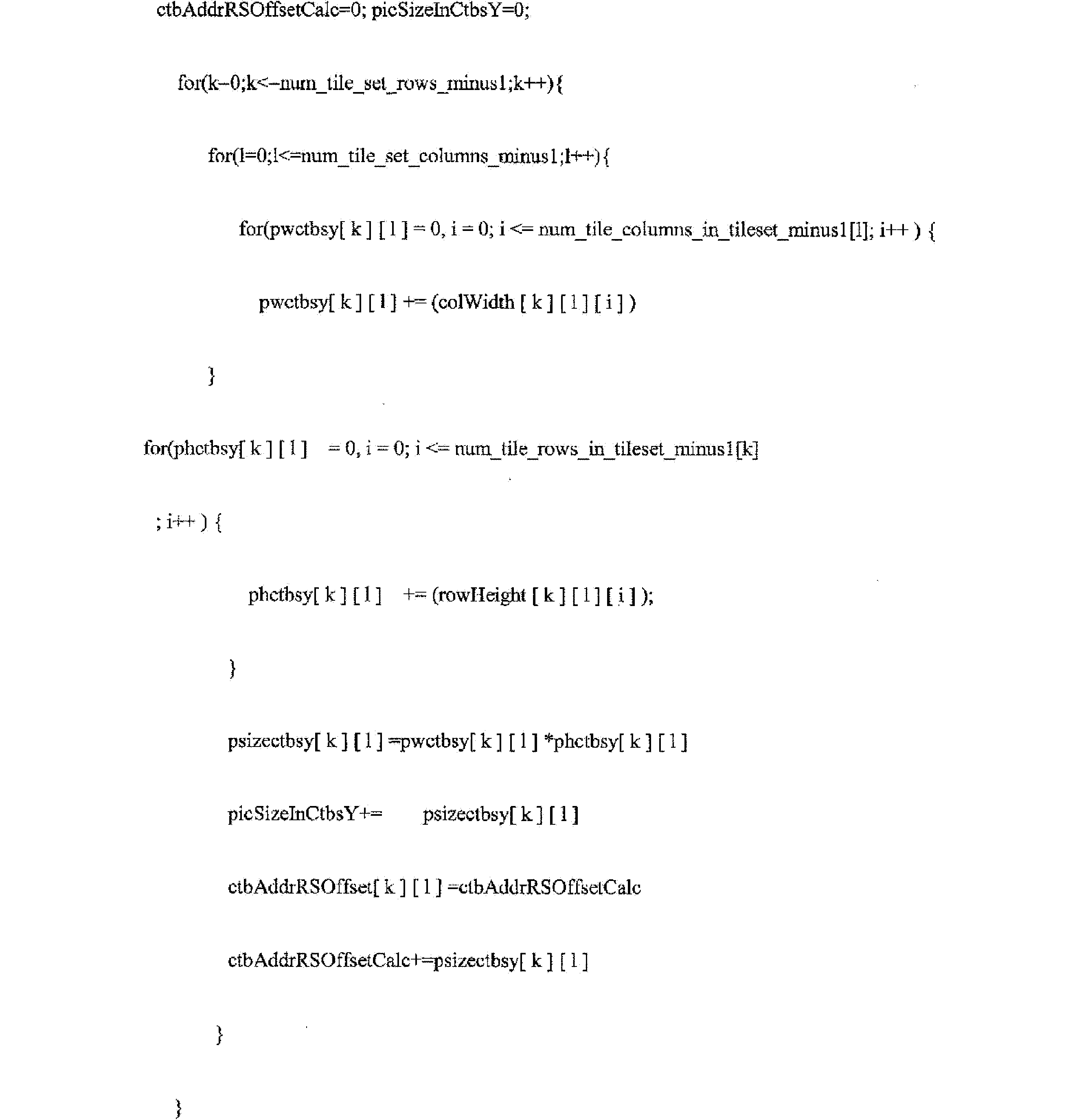
一実施例では、上述のように、 In one embodiment, as described above,

j番目のタイルセットは、以下のようにインデックス(k,l)と関連付けられる。j番目のタイルセットは、インデックスjを有するタイルセットと呼ばれることがある。 The jth tileset is associated with index (k,l) as follows: The jth tileset is sometimes referred to as the tileset with index j.
タイルセットインデックス又はタイルセット識別子jを考慮すると、ピクチャのタイルセット列の数k及びlは、以下のように導出される。 Given a tile set index or tile set identifier j, the number of tile set columns k and l for a picture are derived as follows:

インデックスk及びl並びにピクチャのタイルセット列の数を考慮すると、タイルセットインデックス又はタイルセット識別子jは、以下のように導出される。 Given the indexes k and l and the number of tile set columns in the picture, the tile set index or tile set identifier j is derived as follows:

両端値を含む、0~num_tile_set_rows_minus1の範囲のk、及び両端値を含む、0~num_tile_set_columns_minus1の範囲の1についての各タイルセットにおけるタイルの数は、以下のように導出される。
For k in the

符号化ツリーブロックの単位で、インデックス(k,D)に関連付けられたタイルセットのi番目のタイル列境界の場所を指定する、両端値を含む、0~num_tile_set_rows_minus1の範囲のk、及び両端値を含む、0~num_tile_set_columns_minus1の範囲の1、両端値を含む、0~num_tile_columns_in_tileset_minus1[k]+1の範囲のiについてのリストcolBd[k][l]
[i]は、以下のように導出される。
A list colBd[k][l], for k in the
[i] is derived as follows:
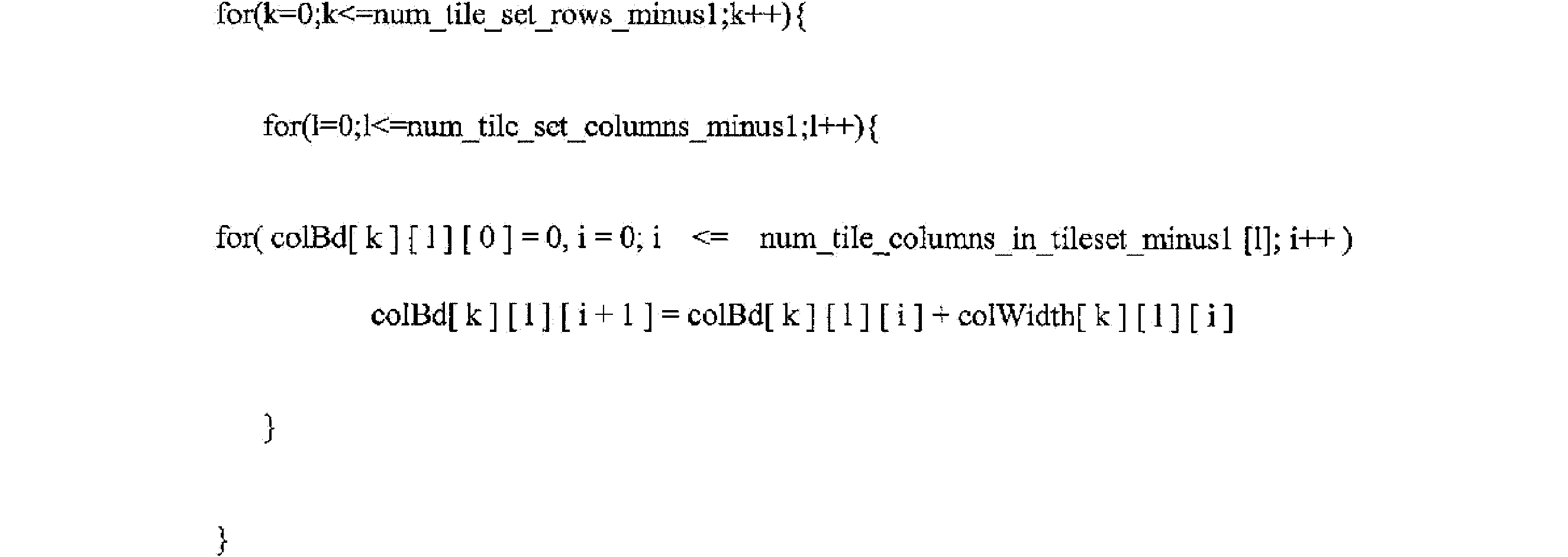
符号化ツリーブロックの単位で、インデックス(k,l)に関連付けられたタイルセットのj番目のタイル行境界の場所を指定する、両端値を含む、0~num_tile_set_rows_minus1の範囲のk、及び両端値を含む、0~num_tile_set_columns_minus1の範囲の1、両端値を含む、0~num_tile_rows_in_tileset_minus1[k]+1の範囲のjについてのリストrowBd[j]は、以下のように導出される。
The list rowBd[j], for k in the

ピクチャのCTBラスタ走査におけるCTBアドレスからタイルセット及びタイル走査におけるCTBアドレスへの変換を指定する、両端値を含む、0~PicSizeInCtbsY-1の範囲のctbAddrRsであるリストCtbAddrRsToTs[ctbAddrRs]は、以下のように導出される。
The list CtbAddrRsToTs[ctbAddrRs], which is a set of ctbAddrRs in the

タイル走査におけるCTBアドレスからピクチャのCTBラスタ走査におけるCTBアドレスへの変換を指定する、両端値を含む、0~PicSizeInCtbsY-1の範囲のctbAddrTsであるリストCtbAddrTsToRs[ctbAddrTs]は、以下のように導出される。
The list CtbAddrTsToRs[ctbAddrTs], which is a set of ctbAddrTs in the

タイル走査におけるCTBアドレスからタイルIDへの変換を指定する、両端値を含む、0~PicSizeInCtbsY-1の範囲のctbAddrTsであるリストTileId[ctbAddrTs]は、以下のように導出される。
The list TileId[ctbAddrTs], which is a set of ctbAddrTs in the

一実施例では、サブビットストリーム抽出又は他のプロセスのために、追加の計算が必要であり得る。一実施例では、更なる計算は、以下のとおりであり得る。 In one embodiment, additional calculations may be required for sub-bitstream extraction or other processes. In one embodiment, the further calculations may be as follows:
両端値を含む、0~num_tile_set_rows_minus1の範囲のk、及び両端値を含む、0~num_tile_set_columns_minus1の範囲の1について、タイル列の数マイナス1及びタイル行の数マイナス1は、以下のように導出される。
For k in the
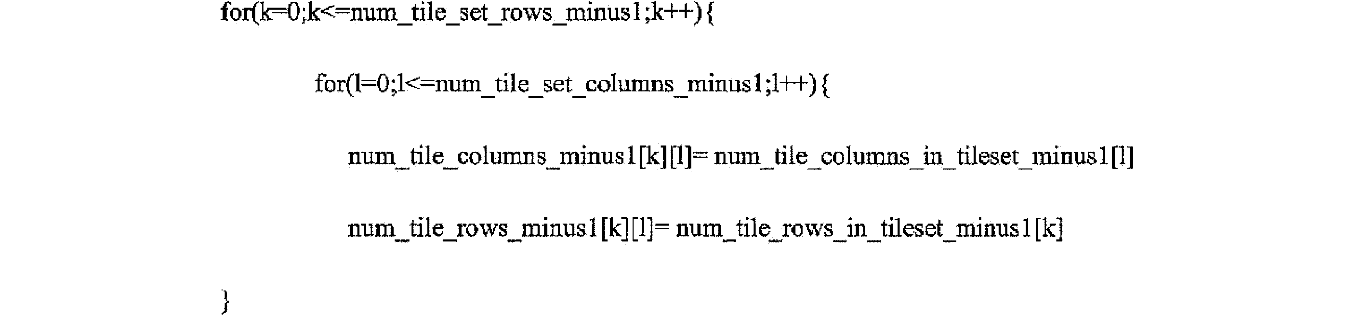
タイルの単位におけるインデックス(*,l)境界に関連付けられたタイルセットの場所を指定する、両端値を含む、0~num_tile_columns_minus1+1の範囲の1についてのリストtilecolumnPos[l]は、以下のように導出される。
The list tilecolumnPos[l], for 1 in the

タイルの単位におけるインデックス(k,*)境界に関連付けられたタイルセットの場所を指定する、両端値を含む、0~num_tile_rows_minus1+1の範囲のkについてのリストtilerowPos[k]は、以下のように導出される。
The list tilerowPos[k], for k in the

符号化ツリーブロックの単位で、インデックス(k,l)に関連付けられたタイルセットのタイル列境界の場所を指定する、両端値を含む、0~num_tile_set_rows_minus1の範囲のk、及び両端値を含む、0~num_tile_set_columns_minus1の範囲の1についてのリストcolBd
[k][l]、及び
符号化ツリーブロックの単位で、インデックス(k,l)に関連付けられたタイルセットのタイル行境界の場所を指定する、両端値を含む、0~num_tile_set_rows_minus1の範囲のk、及び両端値を含む、0~num_tile_set_columns_minus1の範囲の1についてのリストrowBd
[k][l]は、以下のように導出される。
A list colBd for k in the
[k][l], and a list rowBd for k in the
[k][l] is derived as follows:

表9は、タイルセット内のタイルセット及びタイルのそれぞれが、本明細書の技術に従って独立して処理され得るように、情報をシグナリングするために使用され得る、例示的なスライスセグメントヘッダを示す。この場合、スライスは常に、単一の完全なタイルセットを含む。この場合、スライスヘッダにおいて以下のシグナリングが行われる(代わりにタイルセットヘッダ又はセグメントヘッダ、又はそのような他の同様の名前と呼ばれる場合がある)。 Table 9 shows an example slice segment header that may be used to signal information so that each of the tile sets and tiles within a tile set may be processed independently according to the techniques herein. In this case, a slice always contains a single complete tile set. In this case, the following is signaled in the slice header (which may alternatively be called a tile set header or segment header, or other such similar names):

表9に関して、シンタックス要素tile_set_id、num_entry_point_offsets、offset_len_minus1、及びentry_point_offset_minus1は、以下の定義に基づくことができることに留意されたい。 With respect to Table 9, note that the syntax elements tile_set_id, num_entry_point_offsets, offset_len_minus1, and entry_point_offset_minus1 can be based on the following definitions:
tile_set_idは、このタイルセットのタイルセット識別子を指定する。タイルセットインデックスk及びl並びにピクチャのタイルセット列の数を考慮すると、タイルセットインデックス又はタイルセット識別子jは、以下のように導出される。 tile_set_id specifies the tile set identifier for this tile set. Given the tile set indexes k and l and the number of tile set columns in the picture, the tile set index or tile set identifier j is derived as follows:

タイルセット識別子は、代わりにタイルセットインデックスと呼ばれることがある。tile_set_idシンタックス要素の長さはCeil(Log2(NumTileSets))ビットである。 A tile set identifier is sometimes alternatively called a tile set index. The tile_set_id syntax element is Ceil(Log2(NumTileSets)) bits in length.
num_entry_point_offsets、offset_len_minus1、及びentry_offset_minus1[i]は、ITU-TH.265に提供されるものと同様のセマンティクスを有してもよい。 num_entry_point_offsets, offset_len_minus1, and entry_offset_minus1[i] may have semantics similar to those provided in ITU-TH.265.
一実施例では、tiles_enabled_flagが1に等しいときに、以下が導出される。 In one embodiment, when tiles_enabled_flag is equal to 1, the following is derived:
tilesets_enabled_flagが1に等しい場合: If tilesets_enabled_flag is equal to 1:

そうでなければ(すなわち、tilesets_enabled_flagが0に等しい場合) Otherwise (i.e. tilesets_enabled_flag is equal to 0)

tiles_enabled_flagが0に等しい場合:OffsetInfoPresent=0, NumOffsets=0
別の例では、表10は、タイルセット内のタイルセット及びタイルのそれぞれが、本明細書の技術に従って独立して処理され得るように、情報をシグナリングするために使用され得る、例示的なスライスセグメントヘッダを示す。この場合、スライスは、整数個の完全なタイルセットを含んでもよい。この場合、スライスヘッダにおいて以下のシグナリングが行われる(代わりにタイルセットヘッダ又はセグメントヘッダ、又はそのような他の同様の名前と呼ばれる場合がある)。
If tiles_enabled_flag equals 0: OffsetInfoPresent=0, NumOffsets=0
In another example, Table 10 shows an exemplary slice segment header that may be used to signal information such that each of the tile sets and tiles within a tile set may be processed independently according to the techniques herein. In this case, a slice may contain an integer number of complete tile sets. In this case, the following is signaled in the slice header (which may alternatively be called a tile set header or segment header, or other such similar names):

表10に関して、シンタックス要素tile_set_id、num_entry_point_offsets、offset_len_minus1、及びentry_point_offset_minus1は、以下の定義に基づくことができることに留意されたい。 With respect to Table 10, note that the syntax elements tile_set_id, num_entry_point_offsets, offset_len_minus1, and entry_point_offset_minus1 can be based on the following definitions:
tile_set_idは、このタイルセットのタイルセット識別子を指定する。タイルセットインデックスk及びl並びにピクチャのタイルセット列の数を考慮すると、タイルセットインデックス又はタイルセット識別子jは、以下のように導出される。 tile_set_id specifies the tile set identifier for this tile set. Given the tile set indexes k and l and the number of tile set columns in the picture, the tile set index or tile set identifier j is derived as follows:

タイルセット識別子は、代わりにタイルセットインデックスと呼ばれることがある。 The tileset identifier is sometimes alternatively called the tileset index.
tile_set_idシンタックス要素の長さはCeil(Log2(NumTileSets))ビットである。 The length of the tile_set_id syntax element is Ceil(Log2(NumTileSets)) bits.
num_tile_set_ids_minus1プラス1は、スライス内に存在するタイルセットの数(タイルセットのラスタ走査順)を指定する。num_tile_set_ids_minus1シンタックス要素の長さはCeil(Log2(NumTileSets-1))ビットである。 num_tile_set_ids_minus1 plus 1 specifies the number of tilesets present in the slice (tile set raster scan order). The num_tile_set_ids_minus1 syntax element is Ceil(Log2(NumTileSets-1)) bits in length.
tiles_enabled_flagが1に等しいときに、以下が導出される。 When tiles_enabled_flag is equal to 1, the following is derived:
tilesets_enabled_flagが1に等しい場合: If tilesets_enabled_flag is equal to 1:

そうでなければ(すなわち、tilesets_enabled_flagが0に等しい場合) Otherwise (i.e. tilesets_enabled_flag is equal to 0)

tiles_enabled_flagが0に等しい場合:OffsetInfoPresent = 0, NumOffsets=0
「スライスセグメント」は、代わりに、「スライス」又は「タイルセット」又は「タイルセット」又は「セグメント」又は「マルチctuグループ」又は「タイルグループ」又は「タイルリスト」又は「タイル収集」などと呼ばれ得ることに留意されたい。したがって、これらの単語は、いくつかの場合では、互換的に使用されてもよい。また、同様の名前のデータ構造名は互換可能である。「スライスセグメントヘッダ」は、代わりに、「スライスヘッダ」又は「タイルセットヘッダ」又は「タイルセットヘッダ」又は「セグメントヘッダ」又は「マルチctuグループヘッダ」又は「タイルグループヘッダ」又は「タイルリストヘッダ」又は「タイル収集ヘッダ」などと呼ばれ得ることに留意されたい。したがって、これらの単語は、互換的に使用される。また、同様の名前のデータ構造名は、いくつかの場合では、互換可能に使用されてもよい。
If tiles_enabled_flag equals 0: OffsetInfoPresent = 0, NumOffsets=0
It should be noted that a "slice segment" may alternatively be referred to as a "slice" or a "tile set" or a "tile set" or a "segment" or a "multi-ctu group" or a "tile group" or a "tile list" or a "tile collection" or the like. Thus, these words may be used interchangeably in some cases. Also, similarly named data structure names may be used interchangeably. It should be noted that a "slice segment header" may alternatively be referred to as a "slice header" or a "tile set header" or a "tile set header" or a "segment header" or a "multi-ctu group header" or a "tile group header" or a "tile list header" or a "tile collection header" or the like. Thus, these words may be used interchangeably. Also, similarly named data structure names may be used interchangeably in some cases.
表11は、本明細書の技術によるタイル構造を信号化するために使用され得るパラメータセットのシンタックスの例を示す。一実施例では、表11に含まれる例示的なシンタックスは、PPSに含まれてもよい。他の例では、表11に含まれる例示的なシンタックスは、VPS又はSPS又は他のパラメータセットに含まれてもよい。他の例では、表11に含まれる例示的なシンタックスは、タイルグループヘッダ又はスライスヘッダに含めることができる。 Table 11 shows an example of a parameter set syntax that may be used to signal a tile structure in accordance with the techniques herein. In one embodiment, the example syntax included in Table 11 may be included in a PPS. In other examples, the example syntax included in Table 11 may be included in a VPS or SPS or other parameter set. In other examples, the example syntax included in Table 11 may be included in a tile group header or slice header.
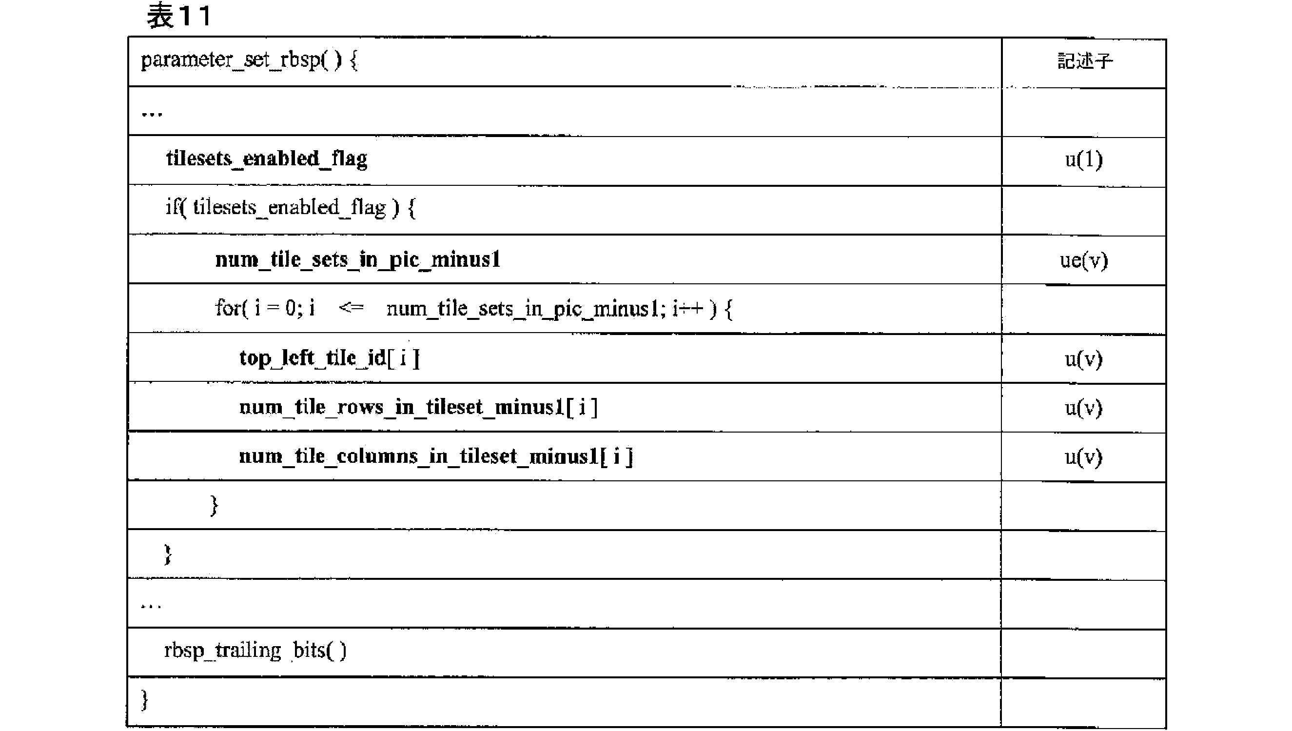
表11に関して、それぞれのシンタックス要素は、以下の定義に基づくことができる。 With respect to Table 11, each syntax element can be based on the following definition:
1に等しいtilesets_enabled_flagは、パラメータセットを参照して、各ピクチャ内に2つ以上のタイルセットが存在することを指定する。0に等しいtilesets_enabled_flagは、パラメータセットを参照して、各ピクチャ内に1つのタイルセットのみが存在することを指定する。変形例では、0に等しいtilesets_enabled_flagは、各タイルが、PPSを参照して、各ピクチャ内のタイルセットであることを指定してもよい。 A tileset_enabled_flag equal to 1 specifies that there is more than one tileset in each picture, with reference to the parameter set. A tileset_enabled_flag equal to 0 specifies that there is only one tileset in each picture, with reference to the parameter set. In a variant, tileset_enabled_flag equal to 0 may specify that each tile is a tileset in each picture, with reference to the PPS.
CVS内でアクティブ化される全てのPPSについては、tilesets_enabled_flagの値が同じであることが、ビットストリームの適合性の要件である。tiles_enabled_flagが0に等しい場合、tilesets_enabled_flagは、0に等しいと推測される。 It is a bitstream conformance requirement that the value of tilesets_enabled_flag be the same for all PPSs activated in CVS. If tiles_enabled_flag is equal to 0, tilesets_enabled_flag is inferred to be equal to 0.
num_tile_sets_in_pic_minus1プラス1は、ピクチャ内のタイルセットの数を指定する。 num_tile_sets_in_pic_minus1 plus 1 specifies the number of tile sets in the picture.
top_left_tile_idは、i番目のタイルセットの左上の角に配置されるタイルのタイルIDを指定する。top_left_tile_id[i]の長さはCeil(Log2(num_tilesets_in_pic_minus1+1))ビットである。jに等しくない任意のiについて、top_left_tile_id[i]の値は、top_left_tile_id[j]の値に等しくないものとする。 top_left_tile_id specifies the tile ID of the tile that is placed in the top-left corner of the i-th tileset. The length of top_left_tile_id[i] is Ceil(Log2(num_tilesets_in_pic_minus1+1)) bits. For any i not equal to j, the value of top_left_tile_id[i] shall not be equal to the value of top_left_tile_id[j].
num_tile_rows_in_tileset_minus1[i]プラス1は、両端値を含む、0~(num_tile sets in pic minus1)の範囲にある各iについて、i番目のタイルセットにおけるタイル行の数を指定する。num_tile_rows_in_tileset_minus1[i]は、両端値を含む、0~num_tile_rows_minus1の範囲にあるものとする。num_tile_rows_in_tileset_minus1[i]の長さはCeil(Log2
(num_tile_rows_minus1+1))ビットである。
num_tile_rows_in_tileset_minus1[i] plus 1 specifies the number of tile rows in the i-th tile set, for each i in the
(num_tile_rows_minus1+1)) bits.
num_tile_rows_in_tileset_minus1[i]の値が存在しない場合、num_tile_rows_in_tileset_minus1[i]の値は0に等しいと推測される。 If the value of num_tile_rows_in_tileset_minus1[i] is not present, the value of num_tile_rows_in_tileset_minus1[i] is inferred to be equal to 0.
変形例では、num_tile_rows_in_tileset_minus1[i]の値が存在しない場合、num_tile_rows_in_tileset_minus1[i]の値はnum_tile_rows_minus1に等しいと推測される。 In a variant, if there is no value for num_tile_rows_in_tileset_minus1[i], the value of num_tile_rows_in_tileset_minus1[i] is inferred to be equal to num_tile_rows_minus1.
num_tile_columns_in_tileset_minus1[l]プラス1は、両端値を含む、0~(num_tile_sets_in_pic_minus1)の範囲にある各iについて、i番目のタイルセットにおけるタイル列の数を指定する。num_tile_columns_in_tileset_minus1[l]は、両端値を含む、0~num_tile_columns_minus1の範囲にあるものとする。num_tile_columnss_in_tileset_minus1[i]の長さはCeil(Log2(num_tile_columns_minus1+1))ビットである。
num_tile_columns_in_tileset_minus1[l] plus 1 specifies the number of tile columns in the i-th tile set, for each i in the
num_tile_columns_in_tileset_minus1[l]の値が存在しない場合、num_tile_columns_in_tileset_minus1[l]の値は0に等しいと推測される。 If the value of num_tile_columns_in_tileset_minus1[l] is not present, the value of num_tile_columns_in_tileset_minus1[l] is inferred to be equal to 0.
変形例では、num_tile_columns_in_tileset_minus1[i]の値が存在しない場合、num_tile_columns_in_tileset_minus1[l]の値はnum_tile_columns_minus1に等しいと推測される。 In a variant, if there is no value for num_tile_columns_in_tileset_minus1[i], the value of num_tile_columns_in_tileset_minus1[l] is inferred to be equal to num_tile_columns_minus1.
変形例では、num_tile_rows_m_tileset_minus1[i]及びnum_tile_columns_in_tileset_minus1[l]は、符号化されたue(v)である。 In a variant, num_tile_rows_m_tileset_minus1[i] and num_tile_columns_in_tileset_minus1[l] are the encoded ue(v).
変形例では、1つ又は2つの別個の追加のシンタックス要素は、num_tile_rows_in_tileset_minus1[i]及び/又はnum_tile_columns_in_tileset_minus1[l]に使用されるビット数をシグナリングする。 In a variant, one or two separate additional syntax elements signal the number of bits used for num_tile_rows_in_tileset_minus1[i] and/or num_tile_columns_in_tileset_minus1[l].
表12は、本明細書の技術によるタイル構造を信号化するために使用され得るパラメータセットのシンタックスの例を示す。一実施例では、表12に含まれる例示的なシンタックスは、PPSに含まれてもよい。他の例では、表12に含まれる例示的なシンタックスは、VPS又はSPS又は他のパラメータセットに含まれてもよい。他の例では、表12に含まれる例示的なシンタックスは、タイルグループヘッダ又はスライスヘッダに含めることができる。 Table 12 shows an example of a parameter set syntax that may be used to signal a tile structure in accordance with the techniques herein. In one embodiment, the example syntax included in Table 12 may be included in a PPS. In other examples, the example syntax included in Table 12 may be included in a VPS or SPS or other parameter set. In other examples, the example syntax included in Table 12 may be included in a tile group header or slice header.

表12に関して、それぞれのシンタックス要素は、上記に提供された定義及び以下の定義に基づくことができる。 With respect to Table 12, each syntax element can be based on the definitions provided above and the following definitions:
1に等しいremaining_tiles_tileset_flagは、シンタックス要素top_left_tile_id[i]、num_tile_rows_in_tileset_minus1[i]、num_tile_columns_in_tileset_minus1[i]によってシグナリングされた(num_tilesets_in_pic_minus1-1)タイルセット内で明示的に指定されたもの以外のピクチャ内の残りのタイルの全てが最後のタイルセットを形成することを指定する。0に等しいremaining_tiles_tileset_flagは、全てのnum_tilesets_in_pic_minus1タイルセットが、シンタックス要素top_left_tile_id[i]、num_tile_rows_in_tileset_minus1[i]、num_tile_columns_in_tileset_minus1[i]をシグナリングすることによって明示的に指定されることを指定する。 remaining_tiles_tileset_flag equal to 1 specifies that all remaining tiles in the picture other than those explicitly specified in the (num_tilesets_in_pic_minus1-1) tile sets signaled by the syntax elements top_left_tile_id[i], num_tile_rows_in_tileset_minus1[i], and num_tile_columns_in_tileset_minus1[i] form the final tile set. remaining_tiles_tileset_flag equal to 0 specifies that all num_tilesets_in_pic_minus1 tile sets are explicitly specified by signaling the syntax elements top_left_tile_id[i], num_tile_rows_in_tileset_minus1[i], and num_tile_columns_in_tileset_minus1[i].
num_tile_rows_in_tileset_minus1[i]プラス1は、両端値を含む、0~(num_tile_sets_in_pic_minus1+!remaining_tiles_tileset_flag-l)の範囲にある各iについて、i番目のタイルセットにおけるタイル行の数を指定する。num_tile_rows_in_tileset_minus1[i]は、両端値を含む、0~num_tile_rows_minus1の範囲にあるものとする。num_tile_rows_in_tileset_minus1[i]の長さはCeil(Log2(num_tile_rows_minus1+1))ビットである。
num_tile_rows_in_tileset_minus1[i] plus 1 specifies the number of tile rows in the i-th tileset, for each i in the
num_tile_rows_in_tileset_minus1[i]の値が存在しない場合、num_tile_rows_in_tileset_minus1[i]の値は0に等しいと推測される。 If the value of num_tile_rows_in_tileset_minus1[i] is not present, the value of num_tile_rows_in_tileset_minus1[i] is inferred to be equal to 0.
変形例では、num_tile_rows_in_tileset_minus1[i]の値が存在しない場合、num_tile_rows_in_tileset_minus1[i]の値はnum_tile_rows_minus1に等しいと推測される。 In a variant, if there is no value for num_tile_rows_in_tileset_minus1[i], the value of num_tile_rows_in_tileset_minus1[i] is inferred to be equal to num_tile_rows_minus1.
num_tile_columns_in_tileset_minus1[l]プラス1は、両端値を含む、0~(num_tile_sets_in_pic_minus1+!remainmg_tiles_tileset_flag-1)の範囲にある各Iについて、i番目のタイルセットにおけるタイル列の数を指定する。num_tile_columns_in_tileset_minus1[l]は、両端値を含む、0~num_tile_columns_minus1の範囲にあるものとする。num_tile_columnss_in_tileset_minus1[i]の長さはCeil(Log2(num_tile_columns_minus1+1))ビットである。
num_tile_columns_in_tileset_minus1[l] plus 1 specifies the number of tile columns in the i-th tile set, for each I in the
num_tile_columns_in_tileset_minus1[l]の値が存在しない場合、num_tile_columns_in_tileset_minus1[l]の値は0に等しいと推測される。 If the value of num_tile_columns_in_tileset_minus1[l] is not present, the value of num_tile_columns_in_tileset_minus1[l] is inferred to be equal to 0.
変形例では、num_tile_columns_in_tileset_minus1[i]の値が存在しない場合、num_tile_columns_in_tileset_minus1[l]の値はnum_tile_columns_minus1に等しいと推測される。 In a variant, if there is no value for num_tile_columns_in_tileset_minus1[i], the value of num_tile_columns_in_tileset_minus1[l] is inferred to be equal to num_tile_columns_minus1.
変形例では、ピクチャ内の各タイルが、0~num_tile_set_minus1(両端値を含む)の範囲のタイルセットを有するタイルセットのうちの1つ及び1つのみに属することを、ビットストリームの適合性の要件とする。
In a variant, a bitstream conformance requirement is that each tile in a picture belongs to one and only one of the tile sets with tile sets in the
表12Aは、本明細書の技術によるタイル構造を信号化するために使用され得るパラメータセットのシンタックスの例を示す。一実施例では、表12Aに含まれる例示的なシンタックスは、PPSに含まれてもよい。他の例では、表12Aに含まれる例示的なシンタックスは、VPS又はSPS又は他のパラメータセットに含まれてもよい。他の例では、表12Aに含まれる例示的なシンタックスは、タイルグループヘッダ又はスライスヘッダに含めることができる。 Table 12A shows an example of a parameter set syntax that may be used to signal a tile structure in accordance with the techniques herein. In one embodiment, the example syntax included in Table 12A may be included in a PPS. In other examples, the example syntax included in Table 12A may be included in a VPS or SPS or other parameter set. In other examples, the example syntax included in Table 12A may be included in a tile group header or slice header.
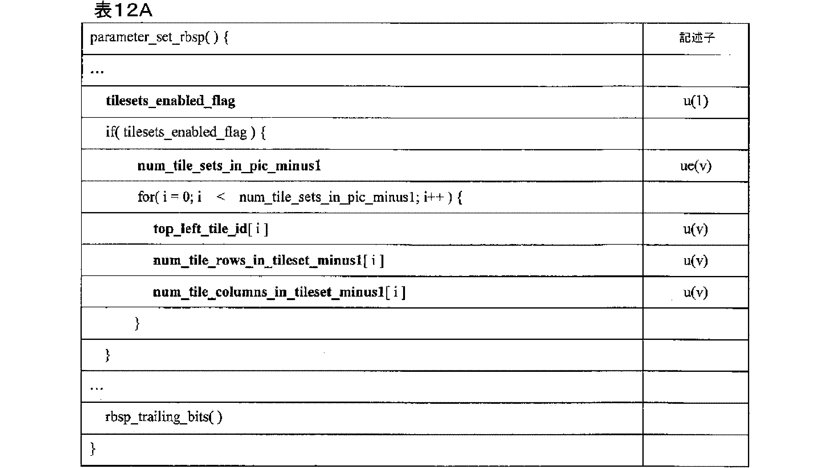
表12Aに関して、それぞれのシンタックス要素は、上記に提供された定義に基づくことができる。 With respect to Table 12A, each syntax element can be based on the definition provided above.
表13は、本明細書の技術によるタイル構造を信号化するために使用され得るパラメータセットのシンタックスの例を示す。一実施例では、表13に含まれる例示的なシンタックスは、PPSに含まれてもよい。他の例では、表13に含まれる例示的なシンタックスは、VPS又はSPS又は他のパラメータセットに含まれてもよい。他の例では、表13に含まれる例示的なシンタックスは、タイルグループヘッダ又はスライスヘッダに含めることができる。 Table 13 shows an example of a parameter set syntax that may be used to signal a tile structure in accordance with the techniques herein. In one embodiment, the example syntax included in Table 13 may be included in a PPS. In other examples, the example syntax included in Table 13 may be included in a VPS or SPS or other parameter set. In other examples, the example syntax included in Table 13 may be included in a tile group header or slice header.

表13に関して、それぞれのシンタックス要素は、上記に提供された定義及び以下の定義に基づくことができる。 With respect to Table 13, each syntax element can be based on the definitions provided above and the following definitions:
bottom_right_tile_id[i]は、i番目のタイルセットの右下の角に配置されるタイルのタイルIDを指定する。bottom_right_tile_id[i]の長さはCeil(Log2(num_tilesets_in_pic_minus1+1))ビットである。jに等しくない任意のiについて、bottom_right_tile_id[i]の値は、bottom_right_tile_id[j]の値に等しくないものとする。 bottom_right_tile_id[i] specifies the tile ID of the tile that is to be placed in the bottom right corner of the i-th tileset. The length of bottom_right_tile_id[i] is Ceil(Log2(num_tilesets_in_pic_minus1+1)) bits. For any i not equal to j, the value of bottom_right_tile_id[i] shall not be equal to the value of bottom_right_tile_id[j].
表14は、本明細書の技術によるタイル構造を信号化するために使用され得るパラメータセットのシンタックスの例を示す。一実施例では、表14に含まれる例示的なシンタックスは、PPSに含まれてもよい。他の例では、表14に含まれる例示的なシンタックスは、VPS又はSPS又は他のパラメータセットに含まれてもよい。他の例では、表14に含まれる例示的なシンタックスは、タイルグループヘッダ又はスライスヘッダに含めることができる。 Table 14 shows an example of a parameter set syntax that may be used to signal a tile structure in accordance with the techniques herein. In one embodiment, the example syntax included in Table 14 may be included in a PPS. In other examples, the example syntax included in Table 14 may be included in a VPS or SPS or other parameter set. In other examples, the example syntax included in Table 14 may be included in a tile group header or slice header.

表14に関して、それぞれのシンタックス要素は、上記に提供された定義に基づくことができる。 With respect to Table 14, each syntax element can be based on the definition provided above.
表11~14に関して、表14Aは、タイルグループヘッダの例示的なシンタックスを示す。 With respect to Tables 11-14, Table 14A shows an example syntax for a tile group header.

表14Aに関して、それぞれのシンタックス要素は、上記に提供された定義及び以下の定義に基づくことができる。 With respect to Table 14A, each syntax element can be based on the definitions provided above and the following definitions:
tile_set_idxは、このタイルセットのタイルセットインデックスを指定する。tile_set_idxシンタックス要素の長さはCeil(Log2(NumTileSets))ビットである。 tile_set_idx specifies the tile set index for this tile set. The length of the tile_set_idx syntax element is Ceil(Log2(NumTileSets)) bits.
表11に関して、表15は、タイルグループデータの例示的なシンタックスを示す。 With respect to Table 11, Table 15 shows an example syntax for tile group data.

表15に関して(With repsect to)、一実施例では、タイル走査におけるCTBアドレスからタイルIDへの変換は、以下のとおりであり得る。 With reference to Table 15, in one embodiment, the conversion from CTB address to tile ID in tile traversal can be as follows:

表12~14に関して、表16は、タイルグループデータの例示的なシンタックスを示す。 With respect to Tables 12-14, Table 16 shows an example syntax for tile group data.
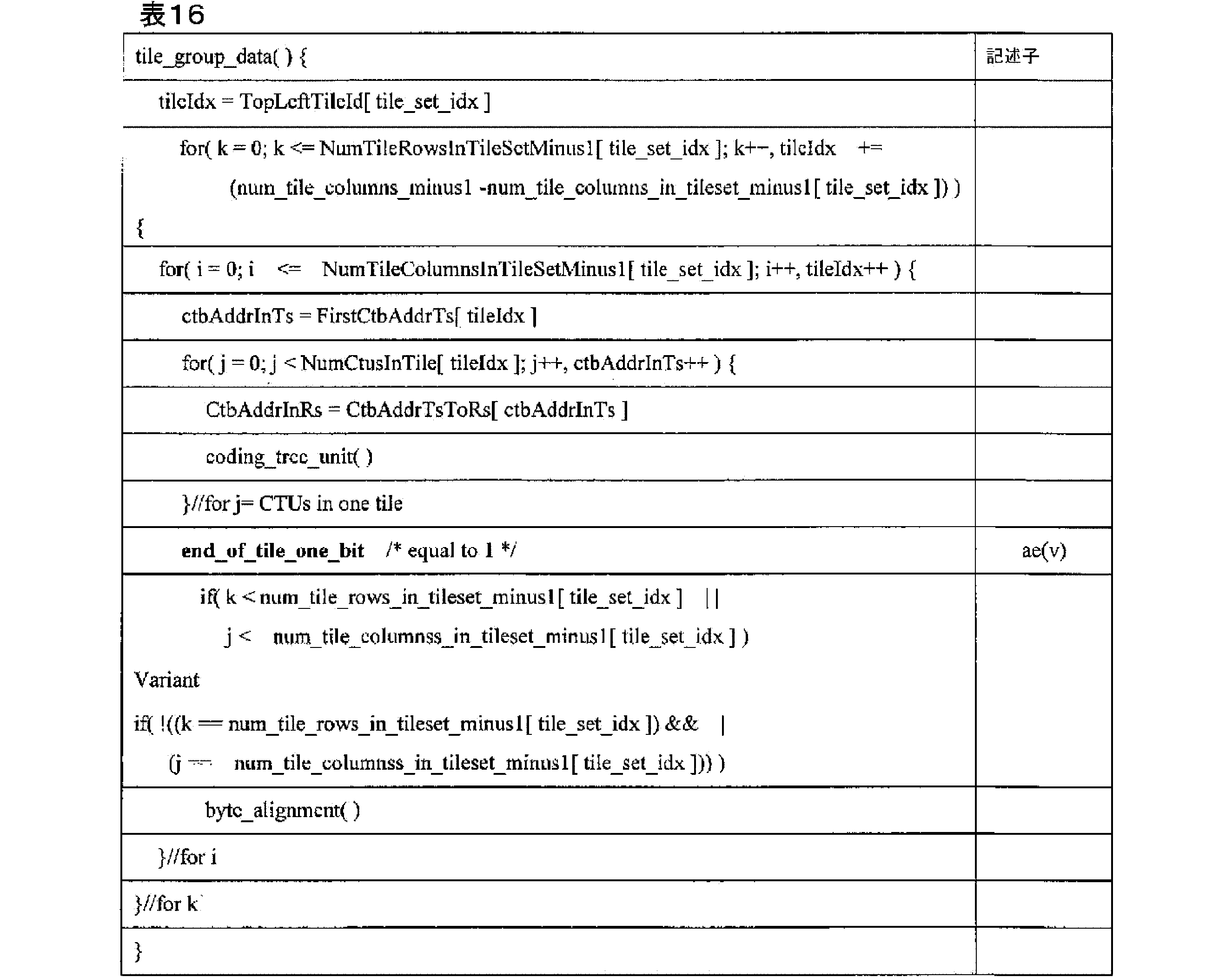
表12~14に関して、表16Aは、タイルグループヘッダの別の例示的なシンタックスを示す。表16と表16Aとの主な違いは、シンタックス要素の一部が、導出された変数によって置き換えられることである。 With respect to Tables 12-14, Table 16A shows another example syntax for a tile group header. The main difference between Table 16 and Table 16A is that some of the syntax elements are replaced by derived variables.
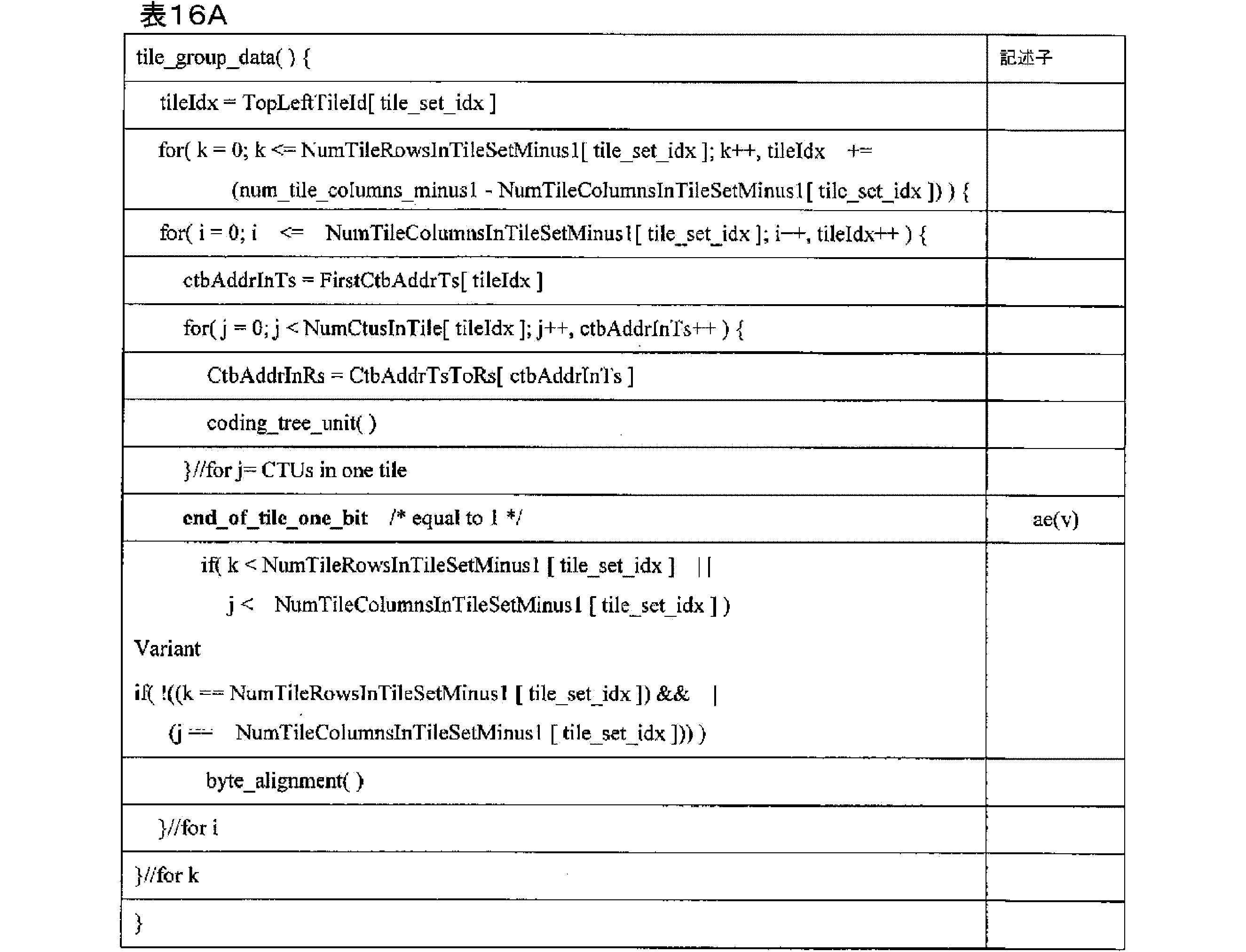
表12及び表16及び表16Aに関して、一実施例では、タイル走査におけるCTBアドレスからタイルIDへの変換は、以下のとおりであり得る。 With reference to Tables 12, 16, and 16A, in one embodiment, the conversion from CTB address to tile ID in tile scanning may be as follows:


表12A及び表16及び表16Aに関して、一実施例では、タイル走査におけるCTBアドレスからタイルIDへの変換は、以下のとおりであり得る。 With reference to Tables 12A, 16, and 16A, in one embodiment, the conversion from CTB address to tile ID in tile scanning may be as follows:


表13及び表16及び表16Aに関して、一実施例では、タイル走査におけるCTBアドレスからタイルIDへの変換は、以下のとおりであり得る。 With reference to Tables 13, 16, and 16A, in one embodiment, the conversion from CTB address to tile ID in tile scanning may be as follows:
タイル走査におけるCTBアドレスからタイルIDへの変換を指定する、両端値を含む、0~PicSizeInCtbsY-1の範囲のctbAddrTsであるリストTileId[ctbAddrTs]、及びタイルにおけるタイルインデックスからCTUの数への変換を指定する、両端値を含む、0~PicSizeInCtbsY-1の範囲のtileIdxであるリストNumCtusInTile[tileIdx]は、以下のように導出される。
The list TileId[ctbAddrTs], which is a ctbAddrTs in the


表14及び表16及び表16Aに関して、一実施例では、タイル走査におけるCTBアドレスからタイルIDへの変換は、以下のとおりであり得る。 With reference to Tables 14, 16, and 16A, in one embodiment, the conversion from CTB address to tile ID in tile scanning may be as follows:
タイル走査におけるCTBアドレスからタイルIDへの変換を指定する、両端値を含む、0~PicSizeInCtbsY-1の範囲のctbAddrTsであるリストTileId[ctbAddrTs]、及びタイルにおけるタイルインデックスからCTUの数への変換を指定する、両端値を含む、0~PicSizeInCtbsY-1の範囲のtileIdxであるリストNumCtusInTile[tileIdx]は、以下のように導出される。
The list TileId[ctbAddrTs], which is a ctbAddrTs in the
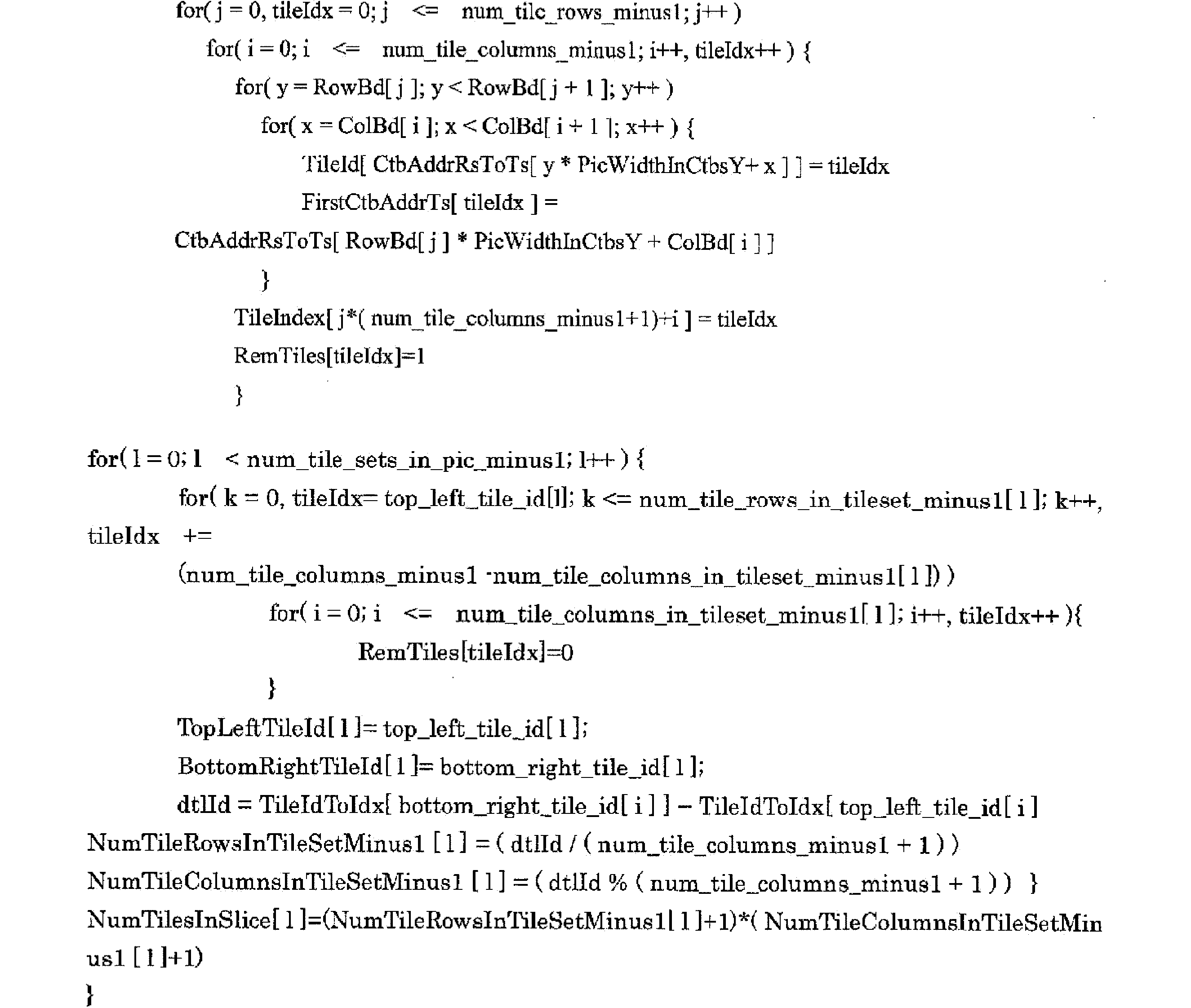

一実施例では、各タイルグループが1つのタイルのみからなることを示すフラグをシグナリングすることができる。タイルグループヘッダ内のタイルグループ内のタイルの数に対するシンタックス要素のシグナリングは、このフラグ上で調整されてもよい。これにより、ビットのソースが提供される。表17は、各タイルグループが1つのタイルのみからなることを示すフラグを含むタイル構造をシグナリングするために使用され得る、ピクチャパラメータセットのシンタックスの例を示す。 In one embodiment, a flag can be signaled to indicate that each tile group consists of only one tile. The signaling of syntax elements for the number of tiles in the tile group in the tile group header may be aligned on this flag, providing a source of bits. Table 17 shows an example of picture parameter set syntax that may be used to signal a tile structure that includes a flag indicating that each tile group consists of only one tile.
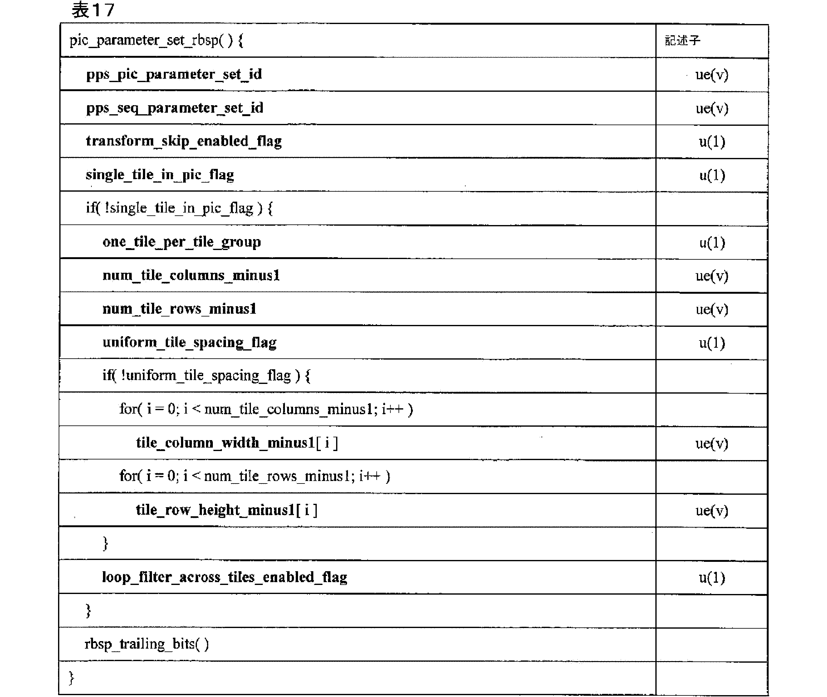
表17に関して、それぞれのシンタックス要素は、上記に提供された定義及び以下の定義に基づくことができる。 With respect to Table 17, each syntax element can be based on the definitions provided above and the following definitions:
1に等しいtransform_skip_enabled_flagは、transform_skip_flagが残差符号化シンタックスに存在し得ることを指定する。0に等しいtransform_skip_enabled_flagは、transform_skip_flagが残差符号化シンタックスに存在しないことを指定する。 transform_skip_enabled_flag equal to 1 specifies that transform_skip_flag may be present in the residual coding syntax. transform_skip_enabled_flag equal to 0 specifies that transform_skip_flag is not present in the residual coding syntax.
1に等しいsingle_tile_in_pic_flagは、PPSを参照して、各ピクチャ内に1つのタイルのみが存在することを指定する。0に等しいsingle_tile_in_pic_flagは、PPSを参照して、各ピクチャ内に2つ以上のタイルが存在することを指定する。 single_tile_in_pic_flag equal to 1 specifies that there is only one tile in each picture, with reference to the PPS. single_tile_in_pic_flag equal to 0 specifies that there is more than one tile in each picture, with reference to the PPS.
CVS内でアクティブ化される全てのPPSについては、single_tile_in_pic_flagの値が同じであることが、ビットストリームの適合性の要件である。 It is a bitstream conformance requirement that all PPSs activated within a CVS have the same value for single_tile_in_pic_flag.
1に等しいone_tile_per_tile_groupは、各タイルグループが1つのタイルを含むことを指定する。0に等しいone_tile_per_tile_groupは、タイルグループが2つ以上のタイルを含み得ることを指定する。 one_tile_per_tile_group equal to 1 specifies that each tile group contains one tile. one_tile_per_tile_group equal to 0 specifies that a tile group may contain two or more tiles.
変形例では、
1に等しいone_tile_per_tile_groupは、各タイルグループが1つのタイルを含むことを指定する。0に等しいone_tile_per_tile_groupは、少なくとも1つのタイルグループが2つ以上のタイルを含むことを指定する。
In a modified example,
one_tile_per_tile_group equal to 1 specifies that each tile group contains one tile. one_tile_per_tile_group equal to 0 specifies that at least one tile group contains two or more tiles.
tile_column_width_minus1プラス1は、符号化ツリーブロックの単位におけるi番目のタイル列の幅を指定する。 tile_column_width_minus1 plus 1 specifies the width of the i-th tile column in units of coding tree blocks.
tile_row_height_minus1[i]プラス1は、符号化ツリーブロックの単位におけるi番目のタイル行の高さを指定する。 tile_row_height_minus1[i] plus 1 specifies the height of the i-th tile row in units of coding tree blocks.
表17に関して、表18は、タイルグループヘッダの例示的なシンタックスを示す。 With reference to Table 17, Table 18 shows an example syntax for a tile group header.

表18に関して、それぞれのシンタックス要素は、上記に提供された定義及び以下の定義に基づくことができる。 With respect to Table 18, each syntax element can be based on the definitions provided above and the following definitions:
存在する場合、タイルグループヘッダシンタックス要素tile_group_pic_parameter_set_idの値は、符号化されたピクチャのタイルグループヘッダの全てにおいて同じであるものとする。 If present, the value of the tile group header syntax element tile_group_pic_parameter_set_id shall be the same in all tile group headers of a coded picture.
tile_group_pic_parameter_set_idは、使用中のPPSのpps_pic_parameter_set_idの値を指定する。tile_group_pic_parameter_set_idの値は、両端値を含む、0~63の範囲にあるものとする。
tile_group_pic_parameter_set_id specifies the value of pps_pic_parameter_set_id for the PPS in use. The value of tile_group_pic_parameter_set_id shall be in the
tile_group_addressは、タイルグループ内の第1のタイルのタイルアドレスを指定する。tile_group_addressの長さはCeil(Log2(NumTilesInPic))ビットである。tile_group_addressの値は、両端値を含む、0~NumTilesInPic-1の範囲にあるものとし、tile_group_addressの値は、同じ符号化ピクチャの任意の他の符号化タイルグループNALユニットのtile_group_addressの値と等しくないものとする。tile_group_addressが存在しない場合、これは0に等しいと推測される。 tile_group_address specifies the tile address of the first tile in the tile group. The length of tile_group_address is Ceil(Log2(NumTilesInPic)) bits. The value of tile_group_address shall be in the range from 0 to NumTilesInPic-1, inclusive, and the value of tile_group_address shall not be equal to the value of tile_group_address of any other coded tile group NAL unit of the same coded picture. If tile_group_address is not present, it is inferred to be equal to 0.
num_tiles_in_tile_group_minus1プラス1は、タイルグループ内のタイルの数を指定する。tile group_minus1におけるタイルの数の値は、両端値を含む、0~NumTilesInPic-1の範囲にあるものとする。num_tiles_in_tile_group_minus1の値が存在しない場合、num_tiles_in_tile_group_minus1の値は0に等しいと推測される。
num_tiles_in_tile_group_minus1 plus 1 specifies the number of tiles in the tile group. The value of the number of tiles in tile group_minus1 shall be in the
変形例では、タイルグループ(minus1)内のタイルの数のシンタックス要素num_tiles_in_tile_group_minus1は、可変長符号化(すなわち、ue(v))の代わりに、固定長符号化(すなわち、u(v))を使用してシグナリングされる。これは、システムレベルでのより容易なパースを可能にし得る。このようなnum_tiles_in_tile_group_minus1は、以下の定義に基づくことができる。 In a variant, the syntax element num_tiles_in_tile_group_minus1 for the number of tiles in a tile group (minus1) is signaled using a fixed length coding (i.e., u(v)) instead of a variable length coding (i.e., ue(v)). This may allow easier parsing at the system level. Such num_tiles_in_tile_group_minus1 may be based on the following definition:
num_tiles_in_tile_group_minus1プラス1は、タイルグループ内のタイルの数を指定する。num_tiles_in_tile_group_minus1の長さはCeil(Log2(NumTilesInPic))ビットである。num_tiles_in_tile_group_minus1の値が存在しない場合、num_tiles_in_tile_group_minus1の値は0に等しいと推測される。 num_tiles_in_tile_group_minus1 plus 1 specifies the number of tiles in the tile group. The length of num_tiles_in_tile_group_minus1 is Ceil(Log2(NumTilesInPic)) bits. If the value of num_tiles_in_tile_group_minus1 is not present, the value of num_tiles_in_tile_group_minus1 is inferred to be equal to 0.
一実施例では、タイルグループ内のタイルの数のシグナリングは、NumTileInPic由来の変数の代わりに、single_tile_in_pic_flagシンタックス要素に基づいて調整されてもよい。シグナリングのためのシンタックス要素を使用すると、シンタックス要素が含まれているか否かを決定するための追加変数の導出及び使用を必要としないことによって、タイルグループヘッダの解析を容易にする。表19は、この実施例のタイルグループヘッダの例示的なシンタックスを示す。 In one embodiment, signaling of the number of tiles in a tile group may be adjusted based on the single_tile_in_pic_flag syntax element instead of the variable derived from NumTileInPic. Using a syntax element for signaling facilitates parsing of the tile group header by not requiring the derivation and use of an additional variable to determine whether the syntax element is included. Table 19 shows an example syntax for the tile group header for this embodiment.

表19に関して、それぞれのシンタックス要素は、上記に提供された定義に基づくことができる。 With respect to Table 19, each syntax element can be based on the definition provided above.
表20は、タイルグループヘッダの別の例示的なシンタックスを示す。 Table 20 shows another example syntax for a tile group header.
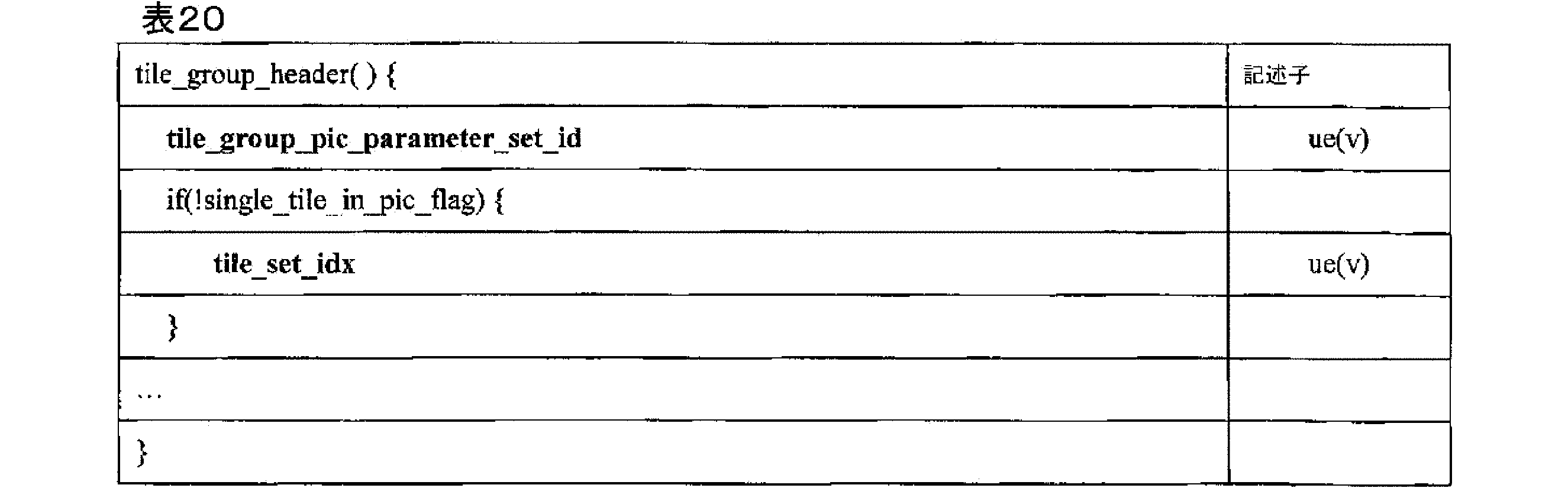
表20に関して、それぞれのシンタックス要素は、上記に提供された定義及び以下の定義に基づくことができる。 With respect to Table 20, each syntax element can be based on the definitions provided above and the following definitions:
tile_set_idxは、このタイルセットのタイルセットインデックスを指定する。tile_set_idシンタックス要素の長さはCeil(Log2(NumTileSets))ビットである。 tile_set_idx specifies the tile set index for this tile set. The length of the tile_set_id syntax element is Ceil(Log2(NumTileSets)) bits.
上述したように、ITU-T H.265は、動き制約タイルセットを可能にするシグナリングを定義し、動き制約タイルセットは、ピクチャ間予測依存性が参照ピクチャ内のコロケーションされたタイルセットに限定されるタイルセットを含んでもよい。一実施例では、タイルセットがMCTSであるかどうかを示すフラグをシグナリングすることができる。表21は、タイルセットがMCTSであるかどうか示すフラグを含むタイル構造をシグナリングするために使用され得る、ピクチャパラメータセットのシンタックスの例がシグナリングされ得ることを示す。 As mentioned above, ITU-T H.265 defines signaling to enable motion constrained tile sets, which may include tile sets where inter-picture prediction dependencies are limited to co-located tile sets in a reference picture. In one embodiment, a flag indicating whether the tile set is an MCTS may be signaled. Table 21 shows an example of picture parameter set syntax that may be used to signal a tile structure including a flag indicating whether the tile set is an MCTS.
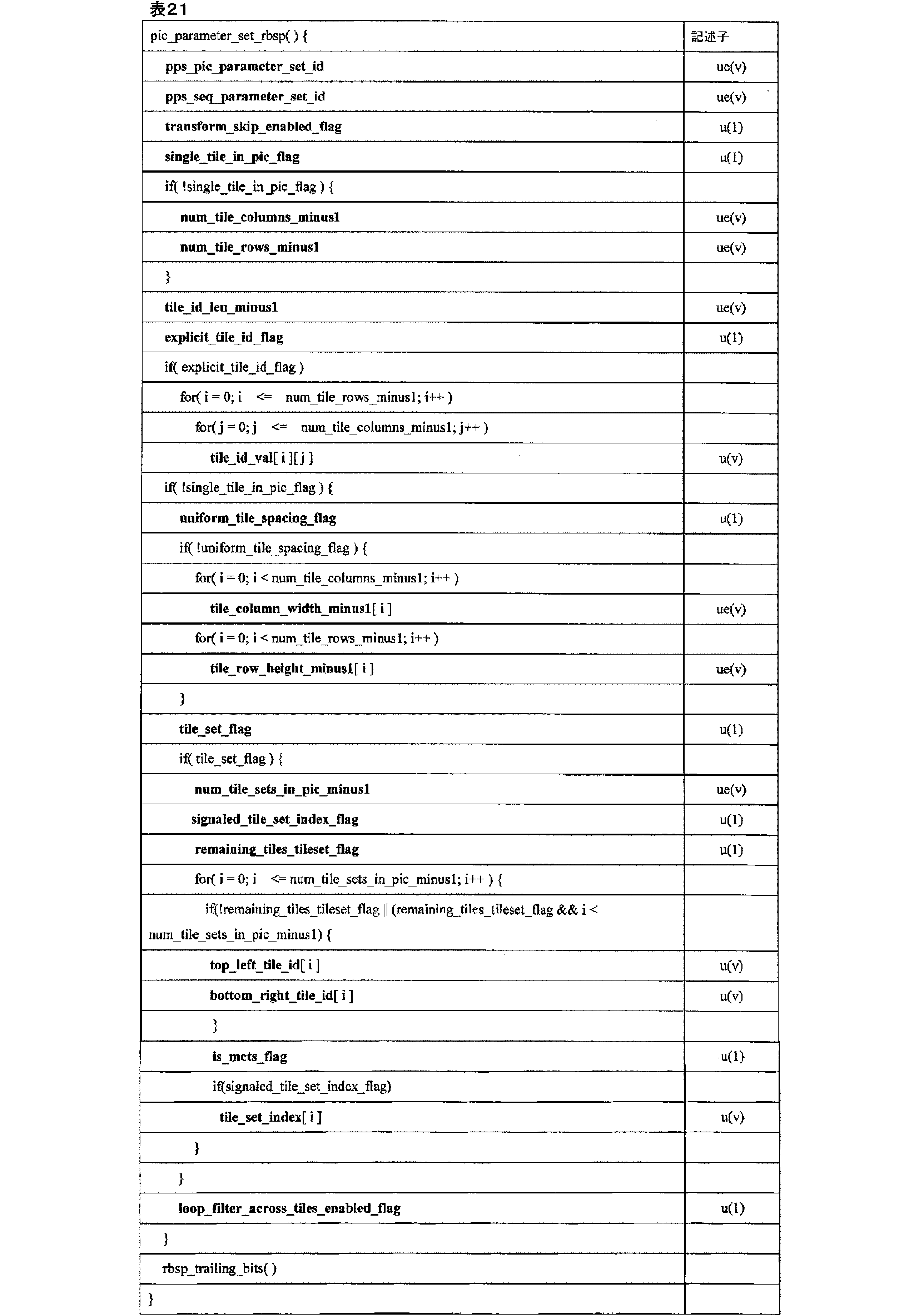
表21に関して、それぞれのシンタックス要素は、以下の定義に基づくことができる。 With respect to Table 21, each syntax element can be based on the following definition:
pps_pic_parameter_set_idは、他のシンタックス要素による参照のためのPPSを指定する。pps_pic_parameter_set_idの値は、両端値を含む、0~63の範囲にあるものとする。
The pps_pic_parameter_set_id specifies the PPS for reference by other syntax elements. The value of pps_pic_parameter_set_id shall be in the
pps_seq_parameter_set_idは、アクティブSPSについてのsps_seq_parameter_set_idの値を指定する。pps_seq_parameter_set_idの値は、両端値を含む、0~15の範囲にあるものとする。
pps_seq_parameter_set_id specifies the value of sps_seq_parameter_set_id for the active SPS. The value of pps_seq_parameter_set_id shall be in the
1に等しいtransform_skip_enabled_flagは、transform_skip_flagが残差符号化シンタックスに存在し得ることを指定する。0に等しいtransform_skip_enabled_flagは、transform_skip_flagが残差符号化シンタックスに存在しないことを指定する。 transform_skip_enabled_flag equal to 1 specifies that transform_skip_flag may be present in the residual coding syntax. transform_skip_enabled_flag equal to 0 specifies that transform_skip_flag is not present in the residual coding syntax.
1に等しいsingle_tile_in_pic_flagは、PPSを参照して、各ピクチャ内に1つのタイルのみが存在することを指定する。0に等しいsingle_tile_in_pic_flagは、PPSを参照して、各ピクチャ内に2つ以上のタイルが存在することを指定する。 single_tile_in_pic_flag equal to 1 specifies that there is only one tile in each picture, with reference to the PPS. single_tile_in_pic_flag equal to 0 specifies that there is more than one tile in each picture, with reference to the PPS.
CVS内でアクティブ化される全てのPPSについては、single_tile_in_pic_flagの値が同じであることが、ビットストリームの適合性の要件である。 It is a bitstream conformance requirement that all PPSs activated within a CVS have the same value for single_tile_in_pic_flag.
num_tile_columns_minus1プラス1は、ピクチャを区画するタイル列の数を指定する。num_tile_columns_minus1は、両端値を含む、0~PicWidthInCtbsY-1の範囲にあるものとする。num_tile_columns_minus1の値が存在しない場合、num_tile_columns_minus1の値は0に等しいと推測される。 num_tile_columns_minus1 plus 1 specifies the number of tile columns that divide the picture. num_tile_columns_minus1 shall be in the range from 0 to PicWidthInCtbsY-1, inclusive. If no value for num_tile_columns_minus1 is present, the value of num_tile_columns_minus1 is inferred to be equal to 0.
num_tile_rows_minus1プラス1は、ピクチャを区画するタイル行の数を指定する。num_tile_rows_minus1は、両端値を含む、0~PicHeightInCtbsY-1の範囲にあるものとする。num_tile_rows_minus1の値が存在しない場合、num_tile_rows_minus1の値は0に等しいと推測される。 num_tile_rows_minus1 plus 1 specifies the number of tile rows that divide the picture. num_tile_rows_minus1 shall be in the range from 0 to PicHeightInCtbsY-1, inclusive. If no value for num_tile_rows_minus1 is present, the value of num_tile_rows_minus1 is inferred to be equal to 0.
変数NumTilesInPicは、(num_tile_columns_minus1+1)*(num_tile_rows_minus1+1)に等しく設定される。 The variable NumTilesInPic is set equal to (num_tile_columns_minus1+1) * (num_tile_rows_minus1+1).
single_tile_in_pic_flagが0である場合、NumTilesInPicは0よりも大きいものとする。 If single_tile_in_pic_flag is 0, NumTilesInPic shall be greater than 0.
tile_id_len_minus1プラス1は、存在する場合、PPS内のシンタックス要素tile_id_val[i][j]、top_left_tile_id[i]、及びbottom_right_tile_id[i]を表すために使用されるビット数を指定する。tile_id_len_minus1の値は、両端値を含む、Ceil(Log2(NumTilesInPic)~15の範囲にあるものとする。 tile_id_len_minus1 plus 1, if present, specifies the number of bits used to represent the syntax elements tile_id_val[i][j], top_left_tile_id[i], and bottom_right_tile_id[i] in the PPS. The value of tile_id_len_minus1 shall be in the range Ceil(Log2(NumTilesInPic) to 15, inclusive.
1に等しいexplicit_tile_id_flagは、各タイルのタイルIDが明示的にシグナリングされることを指定する。0に等しいexplicit_tile_id_flagは、タイルIDが明示的にシグナリングされないことを指定する。 explicit_tile_id_flag equal to 1 specifies that the tile ID for each tile is explicitly signaled. explicit_tile_id_flag equal to 0 specifies that the tile ID is not explicitly signaled.
tile_id_val[i][j]は、i番目のタイル行及びj番目のタイル列のタイルのタイルIDを指定する。tile_id_val[i][j]の長さは、tile_id_len_minus1+1ビットである。 tile_id_val[i][j] specifies the tile ID of the tile in the i-th tile row and j-th tile column. The length of tile_id_val[i][j] is tile_id_len_minus1+1 bits.
0~num_tile_column_minus1(両端値を含む)までの範囲の任意の整数m、及び0~num_titile_row_minus1(両端値を含む)までの範囲の任意の整数nについて、iがmに等しくなく、又はjがnに等しくない場合、tile_id_val[i][j]は、tile_id_val[m][n]に等しくないものである、j*(num_tile_columns_minus1+1)+iが、n*(num_tile_columns_minus1+1)+m未満である場合、tile_id_val[i][j]は、tile_id_val[m][n]未満であるものとする。 For any integer m in the range of 0 to num_tile_column_minus1 (inclusive), and any integer n in the range of 0 to num_tile_row_minus1 (inclusive), if i is not equal to m or j is not equal to n, then tile_id_val[i][j] is not equal to tile_id_val[m][n]. If j * (num_tile_columns_minus1+1) + i is less than n * (num_tile_columns_minus1+1) + m, then tile_id_val[i][j] is less than tile_id_val[m][n].
1に等しいuniform_tile_spacing_flagは、タイル列境界及び同様にタイルの行境界が、ピクチャにわたって均一に分布されることを指定する。0に等しいuniform_tile_spacing_flagは、タイル列境界及び同様にタイルの行境界が、ピクチャにわたって均一に分布されないが、シンタックス要素tile_column_width_minus1[i]及びtile_row_height_minus1[i]を使用して明示的にシグナリングされることを指定する。uniform_tile_spacing_flagが存在しない場合、uniform_tile_spacing_flagの値は1に等しいと推測される。 uniform_tile_spacing_flag equal to 1 specifies that tile column borders, and similarly tile row borders, are uniformly distributed across the picture. uniform_tile_spacing_flag equal to 0 specifies that tile column borders, and similarly tile row borders, are not uniformly distributed across the picture, but are explicitly signaled using the syntax elements tile_column_width_minus1[i] and tile_row_height_minus1[i]. If uniform_tile_spacing_flag is not present, the value of uniform_tile_spacing_flag is inferred to be equal to 1.
tile_column_width_minus1[i]プラス1は、CTBの単位におけるi番目のタイル列の幅を指定する。 tile_column_width_minus1[i] plus 1 specifies the width of the i-th tile column in CTB units.
tile_row_height_minus1[i]プラス1は、CTBの単位におけるi番目のタイル行の高さを指定する。以下の変数は、CTBラスタ及びタイル走査変換プロセスを呼び出すことによって導出される:
-CTBの単位で、i番目のタイル列の幅を指定する、両端値を含む、0~num_tile_columns_minus1の範囲のiについてのリストColWidth[i]、
-CTBの単位で、j番目のタイル行の高さを指定する、両端値を含む、0~num_tile_rows_minus1の範囲のjについてのリストRowHeight[j]、
-CTBの単位で、i番目のタイル列境界の場所を指定する、両端値を含む、0~num_tile_columns_minus1+1の範囲のiについてのリストColBd[i]、
-CTBの単位で、j番目のタイル行境界の場所を指定する、両端値を含む、0~num_tile_rows_minus1+1の範囲のjについてのリストRowBd[j]、
ピクチャのCTBラスタ走査におけるCTBアドレスからタイル走査におけるCTBアドレスへの変換を指定する、両端値を含む、0~PicSizeInCtbsY-1の範囲のctbAddrRsであるリストCtbAddrRsToTs[ctbAddrRs]、
-タイル走査におけるCTBアドレスからピクチャのCTBラスタ走査におけるCTBアドレスへの変換を指定する、両端値を含む、0~PicSizeInCtbsY-1の範囲のctbAddrTsであるリストCtbAddrTsToRs[ctbAddrTs]、
-タイル走査におけるCTBアドレスからタイルIDへの変換を指定する、両端値を含む、0~PicSizeInCtbsY-1の範囲のctbAddrTsであるリストTileId[ctbAddrTs]、
-タイルにおけるタイルインデックスからCTUの数への変換を指定する、両端値を含む、0~PicSizeInCtbsY-1の範囲のtileIdxであるリストNumCtusInTile[tileIdx]、
-タイルIDからタイルインデックスへの変換を指定するNumTilesInPic tileId値のセットについてのセット[TileIdToIdx[tileId]、及びタイル内の第1のCTBのタイル走査におけるタイルIDからCTBアドレスへの変換を指定する、両端値を含む、0~NumTilesInPic-1の範囲のtileIdxについてのリストFirstCtbAddrTs[tileIdx]
-ルマサンプルの単位で、i番目のタイル列の幅を指定する、両端値を含む、0~num_tile_columns_minus1の範囲のiについてのリストColumnWidthInLumaSamples[i]、
-ルマサンプルの単位で、j番目のタイル行の高さを指定する、両端値を含む、0~num_tile_rows_minus1の範囲のjについてのリストRowHeightInLumaSamples[j]。
tile_row_height_minus1[i] plus 1 specifies the height of the i-th tile row in CTB units. The following variables are derived by invoking the CTB raster and tile scan conversion processes:
- a list ColWidth[i], for i in the
- a list RowHeight[j], for j, in the
- a list ColBd[i], for i in the
- a list RowBd[j], for j, in the
A list CtbAddrRsToTs[ctbAddrRs] of ctbAddrRs in the
- a list CtbAddrTsToRs[ctbAddrTs] of ctbAddrTs in the
- a list TileId[ctbAddrTs] of ctbAddrTs in the
- a list NumCtusInTile[tileIdx], which are tileIdx in the
A set [TileIdToIdx[tileId] for a set of NumTilesInPic tileId values that specifies the conversion from tile ID to tile index, and a list FirstCtbAddrTs[tileIdx] for tileIdx in the
- a list ColumnWidthInLumaSamples[i], for i, in the
- A list RowHeightInLumaSamples[j], for j, in the
両端値を含む、0~num_tile_columns_minus1の範囲のiについてのColumnWidthInLumaSamplesf i ]の値、及び両端値を含む、0~num_tile_rows_minus1の範囲のjについてのRowHeightInLumaSamples[j]は、全て0を超えるものとする。
The value of ColumnWidthInLumaSamplesf i for i in the
0に等しいtile_set_flagは、各タイルがタイルセットであることを指定する。1に等しいtile_set_flagは、タイルセットが、シンタックス要素num_tile_sets_in_pic_minus1、top_left_tile_id[i]、及びbottom_right_tile_id[i]によって明示的に指定されることを指定する。 A tile_set_flag equal to 0 specifies that each tile is a tile set. A tile_set_flag equal to 1 specifies that the tile set is explicitly specified by the syntax elements num_tile_sets_in_pic_minus1, top_left_tile_id[i], and bottom_right_tile_id[i].
別の例では、0に等しいtile_set_flagは、各ピクチャが1タイルであることを指定する。 In another example, tile_set_flag equal to 0 specifies that each picture is one tile.
num_tilesets_in_pic_minus1プラス1は、ピクチャ内のタイルセットの数を指定する。num_tilesets_in_pic_minus1の値は、両端値を含む、0~(NumTilesInPic-1)の範囲にあるものとする。存在しない場合、num_tilesets_in_pic_minus1は、(NumTilesInPic-1)であると推測される。別の実施例では、存在しない場合、num_tilesets_in_pic_minus1は、0に等しいと推測される。 num_tilesets_in_pic_minus1 plus 1 specifies the number of tilesets in the picture. The value of num_tilesets_in_pic_minus1 shall be in the range of 0 to (NumTilesInPic-1), inclusive. If not present, num_tilesets_in_pic_minus1 is inferred to be (NumTilesInPic-1). In another embodiment, if not present, num_tilesets_in_pic_minus1 is inferred to be equal to 0.
1に等しいsignaled_tile_set_index_flagは、各タイルセットのタイルセットインデックスがシグナリングされることを指定する。0に等しいsignaled_tile_set_index_flagは、タイルセットインデックスがシグナリングされないことを指定する。 signaled_tile_set_index_flag equal to 1 specifies that the tileset index for each tileset is signaled. signaled_tile_set_index_flag equal to 0 specifies that the tileset index is not signaled.
1に等しいremaining_tiles_tileset_flagは、シンタックス要素top_left_tile_id[i]、num_tile_rows_in_tileset_minus1[i]、num_tile_columns_in_tileset_minus1[i]によってシグナリングされた(num_tilesets_in_pic_minus1-1)タイルセットにおいて明示的に指定されたもの以外のタイルセット内の残りのタイル全てを指定する。 remaining_tiles_tileset_flag equal to 1 specifies all remaining tiles in the tileset other than those explicitly specified in the (num_tilesets_in_pic_minus1-1) tileset signaled by the syntax elements top_left_tile_id[i], num_tile_rows_in_tileset_minus1[i], and num_tile_columns_in_tileset_minus1[i].
最終のタイルセットを形成する。0に等しいremaining_tiles_tileset_flagは、num_tilesets_in_pic_minus1タイルセット全てが、シンタックス要素top_left_tile_id[i]、num_tile_rows_in_tileset_minus1[i]、num_tile_columns_in_tileset_minus1[i]をシグナリングすることによって明示的に指定されることを指定する。 Form the final tileset. remaining_tiles_tileset_flag equal to 0 specifies that all num_tilesets_in_pic_minus1 tilesets are explicitly specified by signaling the syntax elements top_left_tile_id[i], num_tile_rows_in_tileset_minus1[i], and num_tile_columns_in_tileset_minus1[i].
top_left_tile_id[i]は、i番目のタイルセットの左上の角に配置されるタイルのタイルIDを指定する。top_left_tile_id[i]の長さは、tile_id_len_minus1+1ビットである。jに等しくない任意のiについて、top_left_tile_id[i]の値は、top_left_tile_id[j]の値に等しくないものとする。 top_left_tile_id[i] specifies the tile ID of the tile that is to be placed in the top-left corner of the i-th tile set. The length of top_left_tile_id[i] is tile_id_len_minus1+1 bits. For any i not equal to j, the value of top_left_tile_id[i] shall not be equal to the value of top_left_tile_id[j].
bottom_right_tile_id[i]は、i番目のタイルセットの右下の角に配置されるタイルのタイルIDを指定する。bottom_right_tile_id[i]の長さは、tile_id_len_minus1+1ビットである。 bottom_right_tile_id[i] specifies the tile ID of the tile that is placed in the bottom right corner of the i-th tile set. The length of bottom_right_tile_id[i] is tile_id_len_minus1+1 bits.
変数NumTileRowsInSlice[top_left_tile_id[i]]、NumTileColumnsInSlice[top_left_tile_id[i]]、及びNumTilesInSlice[top_left_tile_id[i]]は、以下のように導出される: The variables NumTileRowsInSlice[top_left_tile_id[i]], NumTileColumnsInSlice[top_left_tile_id[i]], and NumTilesInSlice[top_left_tile_id[i]] are derived as follows:
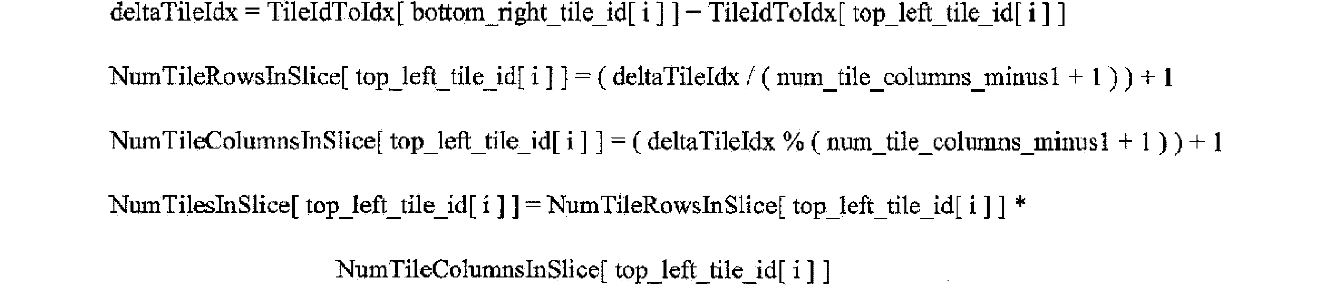
1に等しいis_mcts_flagは、i番目のタイルセットが動き制約タイルセットであることを指定する。0に等しいis_mcts_flagは、i番目のタイルセットが動き制約タイルセットでないことを指定する。 is_mcts_flag equal to 1 specifies that the i-th tile set is a motion constrained tile set. is_mcts_flag equal to 0 specifies that the i-th tile set is not a motion constrained tile set.
一実施例では、0に等しいis_mcts_flagは、i番目のタイルセットが動き制約タイルセットであってもなくてもよいことを指定する。 In one embodiment, is_mcts_flag equal to 0 specifies that the i-th tile set may or may not be a motion constrained tile set.
i番目のタイルセットが動き制約タイルセットである場合、それは、ITU-T H.265のClause D.3.30(すなわち、時間的動き制約タイルセットSEIメッセージ)に記載されているものなどの制約のうちの1つ以上を有し得る。一実施例では、動き制約タイルセットは、時間的動き制約タイルセットと呼ばれることがある。 If the i-th tile set is a motion constrained tile set, it may have one or more of the constraints, such as those described in Clause D.3.30 of ITU-T H.265 (i.e., the temporal motion constrained tile set SEI message). In one embodiment, the motion constrained tile set may be referred to as a temporal motion constrained tile set.
tile_set_index[i]は、i番目のタイルセットのタイルセットインデックスを指定する。tile_set_index[i]シンタックス要素の長さはCeil(Log2(num_tile_sets_in_pic_minus1+1))ビットである。tile_set_index[i]の値が存在しない場合、tile_set_index[i]の値は、両端値を含む、0~num_tile_sets_in_pic_minus1の範囲の各iについて、iに等しいと推測される。 tile_set_index[i] specifies the tile set index for the i-th tile set. The length of the tile_set_index[i] syntax element is Ceil(Log2(num_tile_sets_in_pic_minus1+1)) bits. If the value of tile_set_index[i] is not present, the value of tile_set_index[i] is inferred to be equal to i for each i in the range from 0 to num_tile_sets_in_pic_minus1, inclusive.
1に等しいloop_filter_across_tiles_enabled_flagは、インループフィルタリング操作が、PPSを参照して、ピクチャ内のタイル境界を越えて実行され得ることを指定する。0に等しいloop_filter_across_tiles_enabled_flagは、インループフィルタリング操作が、PPSを参照して、ピクチャ内のタイル境界を越えて実行されないことを指定する。インループフィルタリング操作は、デブロッキングフィルタ、サンプル適応オフセットフィルタ、及び適応ループフィルタ操作を含む。loop_filter_across_tiles_enabled_flagが存在しない場合、loop_filter_across_tiles_enabled_flagの値は1に等しいと推測される。 loop_filter_across_tiles_enabled_flag equal to 1 specifies that in-loop filtering operations may be performed across tile boundaries within a picture with reference to the PPS. loop_filter_across_tiles_enabled_flag equal to 0 specifies that in-loop filtering operations are not performed across tile boundaries within a picture with reference to the PPS. In-loop filtering operations include deblocking filters, sample adaptive offset filters, and adaptive loop filter operations. If loop_filter_across_tiles_enabled_flag is not present, the value of loop_filter_across_tiles_enabled_flag is inferred to be equal to 1.
一実施例では、表21の対応する部分を、以下の表21Aに示すように変更してもよい。 In one embodiment, the corresponding portion of Table 21 may be modified as shown in Table 21A below.

それぞれのシンタックス要素は、上記に提供された定義を有し得る。更に、表21に関して、タイルグループヘッダのシンタックスは、以下の表21Bに示すとおりであってもよい。 Each syntax element may have the definition provided above. Further, with respect to Table 21, the syntax of the tile group header may be as shown in Table 21B below.

表21Bに関して、それぞれのシンタックス要素は、以下のセマンティクス及び定義に基づくことができる。 With respect to Table 21B, each syntax element can be based on the following semantics and definitions:
存在する場合、タイルグループヘッダシンタックス要素tile_group_pic_parameter_set_idの値は、符号化されたピクチャのタイルグループヘッダの全てにおいて同じであるものとする。 If present, the value of the tile group header syntax element tile_group_pic_parameter_set_id shall be the same in all tile group headers of a coded picture.
tile_group_pic_parameter_set_idは、使用中のPPSのpps_pic_parameter_set_idの値を指定する。tile_group_pic_parameter_set_idの値は、両端値を含む、0~63の範囲にあるものとする。
tile_group_pic_parameter_set_id specifies the value of pps_pic_parameter_set_id for the PPS in use. The value of tile_group_pic_parameter_set_id shall be in the
tile_set_idxは、このタイルセットのタイルセットインデックスを指定する。tile_set_idxシンタックス要素の長さは、Ceil(Log2(num_tile_sets_in_pic_minus1+1))ビットである。 tile_set_idx specifies the tile set index for this tile set. The length of the tile_set_idx syntax element is Ceil(Log2(num_tile_sets_in_pic_minus1+1)) bits.
別の例では、tile_set_idxはtile_group_idxと呼ばれる場合があり、以下のようなセマンティクスを有する:
tile_group_idxは、このタイルセットのタイルセットインデックスを指定する。tile_group_idxシンタックス要素の長さは、Ceil(Log2(num_tile_sets_in_pic_minus1+1))ビットである。
In another example, the tile_set_idx may be called tile_group_idx, with the following semantics:
tile_group_idx specifies the tile set index for this tile set. The length of the tile_group_idx syntax element is Ceil(Log2(num_tile_sets_in_pic_minus1+1)) bits.
tile_group_typeは、表21Cに従ってタイルグループの符号化タイプを指定する。 tile_group_type specifies the encoding type of the tile group according to Table 21C.

nal_unit_typeがIRAP_NUTに等しい場合、すなわち、ピクチャはIRAPピクチャであり、tile_groupタイプは2に等しい。 If nal_unit_type is equal to IRAP_NUT, i.e. the picture is an IRAP picture, and tile_group type is equal to 2.
log2_diff_ctu_max_bt_sizeは、バイナリ分割を使用して分割され得る符号化ブロックのルマCTBサイズと最大ルマサイズ(幅又は高さ)との間の差を指定する。log2_diff_ctu_max_bt_sizeの値は、両端値を含む、0~CtbLog2SizeY - MinCbLog2SizeYの範囲にあるものとする。 log2_diff_ctu_max_bt_size specifies the difference between the luma CTB size and the maximum luma size (width or height) of a coding block that can be split using binary splitting. The value of log2_diff_ctu_max_bt_size shall be in the range from 0 to CtbLog2SizeY - MinCbLog2SizeY, inclusive.
log2_diff_ctu_max_bt_sizeの値が存在しない場合、log2_diff_ctu_max_bt_sizeの値は2に等しいと推測される。 If the value of log2_diff_ctu_max_bt_size is not present, the value of log2_diff_ctu_max_bt_size is inferred to be equal to 2.
変数MinQtLog2SizeY、MaxBtLog2SizeY、MinBtLog2SizeY、MaxTtLog2SizeY、MinTtLog2SizeY、MaxBtSizeY、MinBtSizeY、MaxTtSizeY、MinTtSizeY、及びMaxMttDepthは、以下のように導出される: The variables MinQtLog2SizeY, MaxBtLog2SizeY, MinBtLog2SizeY, MaxTtLog2SizeY, MinTtLog2SizeY, MaxBtSizeY, MinBtSizeY, MaxTtSizeY, MinTtSizeY, and MaxMttDepth are derived as follows:

1に等しいsbtmvp_size_override_flagは、シンタックス要素log2_sbtmvp_active_size_minus2が、現在のタイルグループに存在することを指定する。0に等しいsbtmvp_size_override_flagは、シンタックス要素log2_atmvp_active_size_minus2が存在せず、log2_sbtmvp_size_active_minus2がlog2_sbtmvp_default_size_minus2に等しいと推測されることを指定する。 sbtmvp_size_override_flag equal to 1 specifies that the syntax element log2_sbtmvp_active_size_minus2 is present in the current tile group. sbtmvp_size_override_flag equal to 0 specifies that the syntax element log2_atmvp_active_size_minus2 is not present and log2_sbtmvp_size_active_minus2 is inferred to be equal to log2_sbtmvp_default_size_minus2.
log2_sbtmvp_active_size_minus2プラス2は、現在のタイルグループのサブブロックベースのTMVPの運動パラメータを導出するために使用されるサブブロックサイズの値を指定する。log2_sbtmvp_size_active_minus2が存在しない場合、log2_sbtmvp_default_size_minus2に等しいと推測される。変数は、以下のように導出される。 log2_sbtmvp_active_size_minus2 plus 2 specifies the value of the subblock size used to derive the subblock-based TMVP motion parameters for the current tile group. If log2_sbtmvp_size_active_minus2 is not present, it is inferred to be equal to log2_sbtmvp_default_size_minus2. The variable is derived as follows:

tile_group_temporal_mvp_enabled_flagは、時間的運動ベクトル予測因子がインター予測のために使用され得るかどうかを指定する。tile_group_temporal_mvp_enabled_flagが0に等しい場合、現在のピクチャのシンタックス要素は、現在のピクチャの復号に時間的運動ベクトル予測因子が使用されないように制約されるものとする。そうでなければ(tile_group_temporal_mvp_enabled_flagは1に等しい)、時間的運動ベクトル予測因子は、現在のピクチャの復号に使用されてもよい。log2_sbtmvp_default_size_minus2の値が存在しない場合、log2_sbtmvp_default_size_minus2の値は0に等しいと推測される。 tile_group_temporal_mvp_enabled_flag specifies whether a temporal motion vector predictor may be used for inter prediction. If tile_group_temporal_mvp_enabled_flag is equal to 0, the syntax elements of the current picture shall be constrained such that a temporal motion vector predictor is not used for decoding the current picture. Otherwise (tile_group_temporal_mvp_enabled_flag is equal to 1), a temporal motion vector predictor may be used for decoding the current picture. If the value of log2_sbtmvp_default_size_minus2 is not present, the value of log2_sbtmvp_default_size_minus2 is inferred to be equal to 0.
1に等しいmvd_l1_zero_flagは、mvd_coding(x0,y0,1)シンタックス構造がパースされず、compIdx=0~1についてMvdL1[x0][y0][compIdx]が0に等しく設定されていることを示す。0に等しいmvd_l1_zero_flagは、mvd_coding(x0,y0,1)シンタックス構造がパースされたことを示す。 mvd_l1_zero_flag equal to 1 indicates that the mvd_coding(x0,y0,1) syntax structure has not been parsed and MvdL1[x0][y0][compIdx] for compIdx=0..1 is set equal to 0. mvd_l1_zero_flag equal to 0 indicates that the mvd_coding(x0,y0,1) syntax structure has been parsed.
1に等しいcollocated_from_10_flagは、時間的運動ベクトル予測に使用されるコロケートされたピクチャが参照ピクチャリスト0から導出されることを指定する。0に等しいcollocated_from_10_flagは、時間的運動ベクトル予測に使用されるコロケートされたピクチャが参照ピクチャリスト1から導出されることを指定する。collocated_from_10_flagが存在しない場合、これは1に等しいと推測される。
collocated_from_10_flag equal to 1 specifies that the collocated picture used for temporal motion vector prediction is derived from
six_minus_max_num_merge_candは、6から減算されたタイルグループでサポートされるマージ運動ベクトル予測(MVP)候補の最大数を指定する。MVP候補をマージする最大数MaxNumMergeCandは、以下のように導出される。 six_minus_max_num_merge_cand specifies the maximum number of merge motion vector prediction (MVP) candidates supported in a tile group subtracted from six. The maximum number of merge MVP candidates, MaxNumMergeCand, is derived as follows:

MaxNumMergeCandの値は、両端値を含む、1~6の範囲にあるものとする。 The value of MaxNumMergeCand must be in the range of 1 to 6, inclusive.
0に等しいdep_quant_enabled_flagは、依存量子化が無効化されることを指定する。1に等しいdep_quant_enabled_flagは、依存量子化が有効化されることを指定する。 dep_quant_enabled_flag equal to 0 specifies that dependent quantization is disabled. dep_quant_enabled_flag equal to 1 specifies that dependent quantization is enabled.
0に等しいsign_data_hiding_enabled_flagは、サインビットハイディングが無効化されることを指定する。1に等しいsign_data_hiding_enabled_flagは、サインビットハイディングが有効化されることを指定する。sign_data_hiding_enabled_flagが存在しない場合、これは0に等しいと推測される。 sign_data_hiding_enabled_flag equal to 0 specifies that sign bit hiding is disabled. sign_data_hiding_enabled_flag equal to 1 specifies that sign bit hiding is enabled. If sign_data_hiding_enabled_flag is not present, it is inferred to be equal to 0.
offset_len_minus1プラス1は、entry_point_offset_minus1[i]シンタックス要素の長さ (ビット)を指定する。offset_len_minus1の値は、両端値を含む、0~31の範囲にあるもの
とする。
offset_len_minus1 plus 1 specifies the length (in bits) of the entry_point_offset_minus1[i] syntax element. The value of offset_len_minus1 shall be in the
entry_point_offset_minus1[i]プラス1は、i番目のエントリポイントオフセット(バイト)を指定し、offset_len_minus1プラス1ビットで表される。スライスデータは、スライスのヘッダに続き、NumTilesInSlice[tile_set_idx]サブセットからなり、サブセットインデックス値は、両端値を含む、0~NumTilesInSlice[tile_set_idx]-1の範囲である。スライスデータの第1のバイトは、バイト0と見なされる。存在する場合、符号化スライスNALユニットのスライスデータ部分に現れるエミュレーション防止バイトは、サブセット識別の目的でスライスデータの一部としてカウントされる。サブセット0は、符号化スライスセグメントデータのバイト0からentry_point_offset_minus1[0](両端値を含む)からなり、kが1~NumTilesInSlice[tile_set_idx]-2(両端値を含む)の範囲のkを有するサブセットkは、符号化スライスデータのバイトfirstByte[k]~lastByte[k](両端値を含む)からなり、firstByte[k]及びlastByte[k]は、以下のとおり定義される。
entry_point_offset_minus1[i] plus 1 specifies the i-th entry point offset (in bytes) and is represented by offset_len_minus1 plus 1 bits. The slice data follows the slice header and consists of NumTilesInSlice[tile_set_idx] subsets, where subset index values range from 0 to NumTilesInSlice[tile_set_idx]-1, inclusive. The first byte of slice data is considered to be

最後のサブセット(サブセットインデックスがNumTilesInSlice[tile_set_idx]-1に等しい)は、符号化スライスデータの残りのバイトからなる。 The final subset (subset index equal to NumTilesInSlice[tile_set_idx]-1) consists of the remaining bytes of the coded slice data.
各サブセットは、同じタイル内にあるスライス内の全てのCTUの全ての符号化ビットからなるものとする。 Each subset consists of all the coded bits of all the CTUs in the slice that are in the same tile.
更に、表21に関して、tile_group_data()のシンタックスは、以下の表21Dに示すとおりであってもよい。 Further, with respect to Table 21, the syntax of tile_group_data() may be as shown in Table 21D below.

表21Dに関して、それぞれのシンタックス要素は、以下の定義に基づくことができる。 With regard to Table 21D, each syntax element can be based on the following definition:
end_of_tile_one_bitは1に等しいとする。 end_of_tile_one_bit is equal to 1.
本明細書の説明は、スライス及びスライスヘッダという用語を使用するが、これらの用語は、タイルグループ及びタイルグループヘッダの用語にそれぞれ置き換えられてもよいことに留意されたい。加えて、シンタックス要素slice_typeは、シンタックス要素tile_group_typeに置き換えられてもよい。この場合、slice_typeを使用する条件及び他のシンタックス要素をtile_group_typeに変更することができる。加えて、変数NumTilesInSliceは、シンタックス要素NumTilesInTileGroupに置き換えられてもよい。更に、本明細書に記載される実施例の説明は、タイルセットという用語を使用するが、タイルセットの1つ以上の発生はタイルグループという用語と置き換えられてもよいことに留意されたい。更に、単語tile_setを含む名前を有するシンタックス要素のうちの1つ以上は、代わりに単語tile_groupを含む名前で置き換えられてもよい。したがって、1つ以上の以下の変更が行われてもよい。 Note that while the description herein uses the terms slice and slice header, these terms may be replaced with the terms tile group and tile group header, respectively. In addition, the syntax element slice_type may be replaced with the syntax element tile_group_type. In this case, the conditions and other syntax elements that use slice_type may be changed to tile_group_type. In addition, the variable NumTilesInSlice may be replaced with the syntax element NumTilesInTileGroup. Furthermore, while the description of the embodiments described herein uses the term tileset, it is noted that one or more occurrences of tileset may be replaced with the term tile group. Furthermore, one or more of the syntax elements having a name that includes the word tile_set may be replaced with a name that includes the word tile_group instead. Thus, one or more of the following changes may be made:
「タイルセット」を「タイルグループ」に変更する。 Change "Tile Set" to "Tile Group".
「tile_set」を「tile_group」に変更する。 Change "tile_set" to "tile_group".
NumTilesInSliceをNumTilesInTileGroupに変更する。 Change NumTilesInSlice to NumTilesInTileGroup.
NumTileRowsInTileSetMinus1をNumTileRowsInTileGroupMinus1に変更する。 Change NumTileRowsInTileSetMinus1 to NumTileRowsInTileGroupMinus1.
NumTileColumnsInTileSetMinus1をNumTileColumnsInTileGroupMinus1に変更する。 Change NumTileColumnsInTileSetMinus1 to NumTileColumnsInTileGroupMinus1.
tile_set_idxをtile_group_idxに変更する。 Change tile_set_idx to tile_group_idx.
num_tile_sets_in_pic_minus1をnum_tile_groups_in_pic_minus1に変更する。 Change num_tile_sets_in_pic_minus1 to num_tile_groups_in_pic_minus1.
signaled_tile_set_index_flagをsignaled_tile_group_index_flagに、又はexplicit_tile_group_index_flagに変更する。 Change signaled_tile_set_index_flag to signaled_tile_group_index_flag or explicit_tile_group_index_flag.
remaining_tiles_tileset_flagをremaining_tiles_tilegroup_flagに変更する。 Change remaining_tiles_tileset_flag to remaining_tiles_tilegroup_flag.
tile_set_indexをtile_group_indexに変更する。 Change tile_set_index to tile_group_index.
表22A及び表22Bは、本明細書の技術によるタイル構造を信号化するために使用され得るピクチャパラメータセットのシンタックスの例を示す。 Tables 22A and 22B show example picture parameter set syntax that may be used to signal a tile structure in accordance with the techniques of this specification.


表22A、22B、及び22Cに関して、それぞれのシンタックス要素は、上記に提供されたセマンティクス及び定義並びに以下のセマンティクス及び定義に基づくことができる。 With respect to Tables 22A, 22B, and 22C, each syntax element may be based on the semantics and definitions provided above and the following:
1に等しいone_tile_per_tile_groupは、このPPSを指す各タイルグループが1つのタイルを含むことを指定する。0に等しいone_tile_per_tile_groupは、このPPSを指すタイルグループが2つ以上のタイルを含み得ることを指定する。 one_tile_per_tile_group equal to 1 specifies that each tile group that points to this PPS contains one tile. one_tile_per_tile_group equal to 0 specifies that tile groups that point to this PPS may contain two or more tiles.
別の実施例では、
1に等しいone_tile_per_tile_group_flagは、PPSを指す各タイルグループが1つのタイルをちょうど含むことを指定する。0に等しいone_tile_per_tile_group_flagは、PPSを指す各タイルグループが1つ以上のタイルを含むことを指定する。
In another embodiment,
one_tile_per_tile_group_flag equal to 1 specifies that each tile group that points to a PPS contains exactly one tile. one_tile_per_tile_group_flag equal to 0 specifies that each tile group that points to a PPS contains one or more tiles.
0に等しいrect_tile_group_flagは、タイルグループ内のタイルがラスタ走査順であり、タイルグループ情報は、PPSにおいてシグナリングされないことを指定する。1に等しいrect_tile_group_flagは、矩形タイルグループ情報が、bottom_right_tile_id[i]が存在する場合、シンタックス要素num_tile_groups_in_pic_minus1、top_left_tile_id[i]によって明示的に指定されることを指定する。 rect_tile_group_flag equal to 0 specifies that the tiles in the tile group are in raster scan order and no tile group information is signaled in the PPS. rect_tile_group_flag equal to 1 specifies that the rectangular tile group information is explicitly specified by the syntax elements num_tile_groups_in_pic_minus1, top_left_tile_id[i], if bottom_right_tile_id[i] is present.
0に等しいtile_group_flagは、各タイルがタイルグループであることを指定する。1に等しいtile_group_flagは、タイルグループが、シンタックス要素num_tile_groups_in_pic_minus1、top_left_tile_id[i]、及びbottom_right_tile_id[i]によって明示的に指定されることを指定する。 A tile_group_flag equal to 0 specifies that each tile is a tile group. A tile_group_flag equal to 1 specifies that the tile groups are explicitly specified by the syntax elements num_tile_groups_in_pic_minus1, top_left_tile_id[i], and bottom_right_tile_id[i].
別の実施例では、
0に等しいtile_group_flagは、各タイルがタイルグループであることを指定する。1に等しいtile_group_flagは、タイルグループが、シンタックス要素num_tile_groups_in_pic_minus1、top_left_tile_id[i]、及びbottom_right_tile_id[i]によって明示的に指定されることを指定する。
In another embodiment,
Tile_group_flag equal to 0 specifies that each tile is a tile group. Tile_group_flag equal to 1 specifies that the tile group is explicitly specified by the syntax elements num_tile_groups_in_pic_minus1, top_left_tile_id[i], and bottom_right_tile_id[i].
signalled_tile_group_index_length_minus1プラス1は、存在する場合、シンタックス要素tile_group_index[i]、及びtile_group_idを表すために使用されるビット数を指定する。signalled_tile_group_index_length_minus1の値は、両端値を含む、0~15の範囲にあるものとする。
signalled_tile_group_index_length_minus1 plus 1, if present, specifies the number of bits used to represent the syntax elements tile_group_index[i] and tile_group_id. The value of signalled_tile_group_index_length_minus1 shall be in the
1に等しいsignalled_tile_group_index_flagは、各タイルグループのタイルセットグループがシグナリングされることを指定する。0に等しいsignalled_tile_group_index_flagは、タイルグループインデックスがシグナリングされないことを指定する。 signalled_tile_group_index_flag equal to 1 specifies that the tile set group of each tile group is signaled. signalled_tile_group_index_flag equal to 0 specifies that the tile group index is not signaled.
num_tile_groups_in_pic_minus1プラス1は、ピクチャ内のタイルグループの数を指定する。num_tile_groups_in_pic_minus1の値は、両端値を含む、0~(NumTilesInPic- 1)の範囲にあるものとする。存在しない場合、num_tile_groups_in_pic_minus1は、(NumTilesInPic-1)であると推測される。
num_tile_groups_in_pic_minus1 plus 1 specifies the number of tile groups in the picture. The value of num_tile_groups_in_pic_minus1 shall be in the
1に等しいremaining_tiles_tile_group_flagは、シンタックス要素top_left_tile_id[i]、num_tile_rows_in_tile_group_minus1[i]、num_tile_columns_in_ttile_group_minus1
[i]によってシグナリングされた(num_tile_groups_in_pic_minus1・1)タイルセット内で明示的に指定されたもの以外のタイルセット内の残りのタイルの全てが最後のタイルセットを形成することを指定する。0に等しいremaining_tiles_tile_group_flagは、全てのnum_tile_groups_in_pic_minus1タイルセットが、シンタックス要素top_left_tile_id[i]、num_tile_rows_in_tile_group_minus1[i]、num_tile_columns_in_tile_group_minus1[i]をシグナリングすることによって明示的に指定されることを指定する。
remaining_tiles_tile_group_flag equal to 1 specifies the number of tiles in the group of the syntax elements top_left_tile_id[i], num_tile_rows_in_tile_group_minus1[i], num_tile_columns_in_ttile_group_minus1
Specifies that all of the remaining tiles in the tile set other than those explicitly specified in the (num_tile_groups_in_pic_minus1 · 1) tile set signaled by [i] form the final tile set. remaining_tiles_tile_group_flag equal to 0 specifies that all num_tile_groups_in_pic_minus1 tile sets are explicitly specified by signaling the syntax elements top_left_tile_id[i], num_tile_rows_in_tile_group_minus1[i], num_tile_columns_in_tile_group_minus1[i].
top_left_tile_id[i]は、i番目のタイルセットの左上の角に配置されるタイルのタイルインデックスを指定する。jに等しくない任意のiについて、top_left_tile_id[i]の値は、top_left_tile_id[j]の値に等しくないものとする。 top_left_tile_id[i] specifies the tile index of the tile that is to be placed in the top-left corner of the i-th tileset. For any i not equal to j, the value of top_left_tile_id[i] shall not be equal to the value of top_left_tile_id[j].
bottom_right_tile_id[i]は、i番目のタイルセットの右下の角に配置されるタイルのタイルインデックスを指定する。one_tile_per_tile_group_flagが1に等しい場合、bottom_right_tile_id[i]は、top_left_tile_id[i]に等しいと推測される。 bottom_right_tile_id[i] specifies the tile index of the tile placed in the bottom right corner of the i-th tileset. If one_tile_per_tile_group_flag is equal to 1, bottom_right_tile_id[i] is inferred to be equal to top_left_tile_id[i].
タイルグループのタイルの数を指定する変数NumTilesInTileGroup[i]、及び関連する変数は、以下のように導出される。 The variable NumTilesInTileGroup[i], which specifies the number of tiles in a tile group, and related variables are derived as follows:

tile_group_index[i]は、i番目のタイルグループのタイルグループインデックスを指定する。tile_group_index[i]シンタックス要素の長さは、signalled_tile_set_index_length_minus1+1ビットである。tile_group_index[i]の値が存在しない場合、tile_group_index[i]の値は、両端値を含む、0~num_tile_groups_in_pic_minus1の範囲の各iについて、iに等しいと推測される。
tile_group_index[i] specifies the tile group index for the i-th tile group. The length of the tile_group_index[i] syntax element is signalled_tile_set_index_length_minus1 + 1 bits. If the value of tile_group_index[i] is not present, the value of tile_group_index[i] is inferred to be equal to i for each i in the
表22A、表22B、表22C、表23A及び表23Bに関して、タイルグループヘッダの例示的なシンタックスを示し、表24は、タイルグループデータの例示的なシンタックスを示す。 Tables 22A, 22B, 22C, 23A and 23B show an example syntax for the tile group header, and Table 24 shows an example syntax for the tile group data.
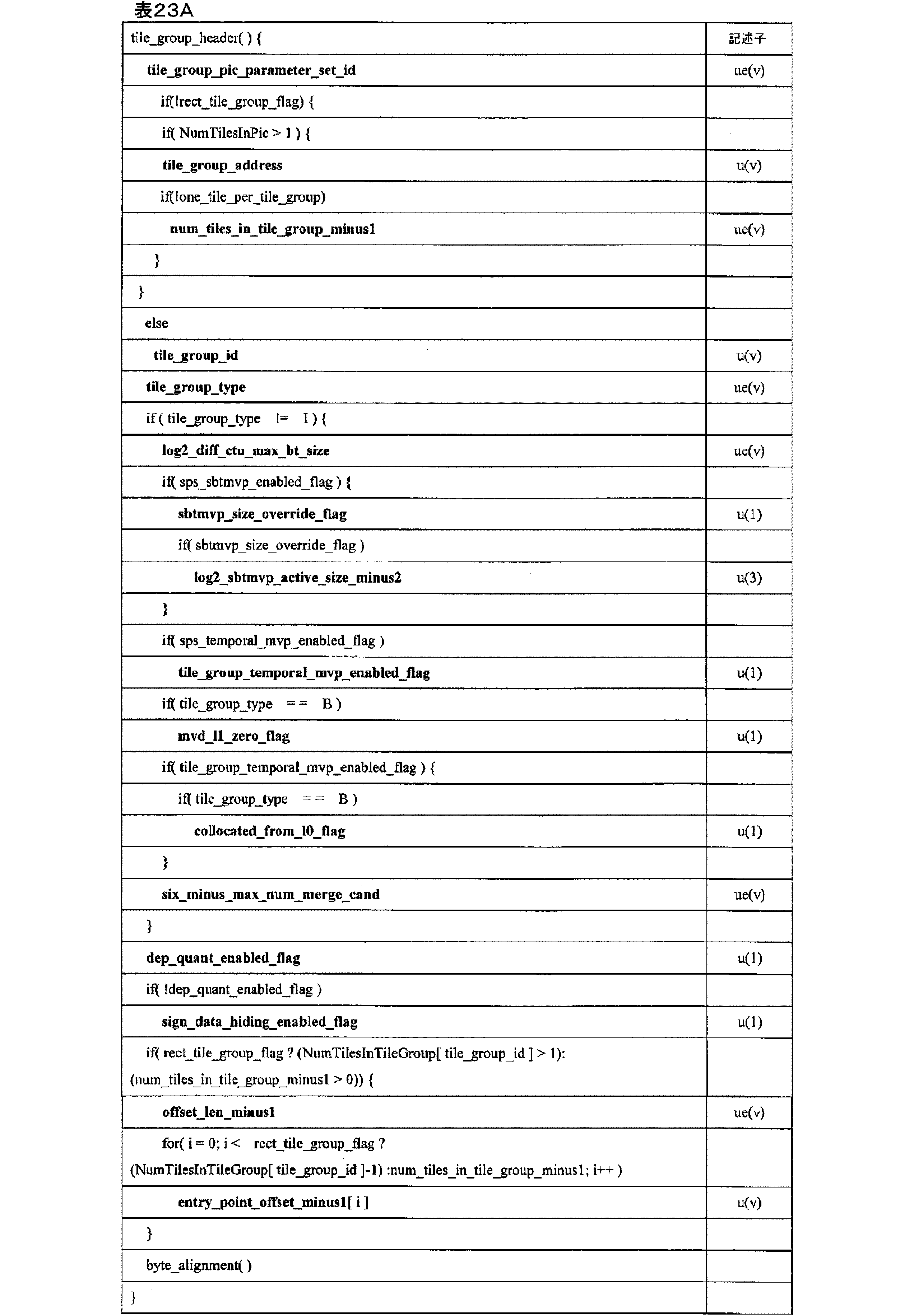

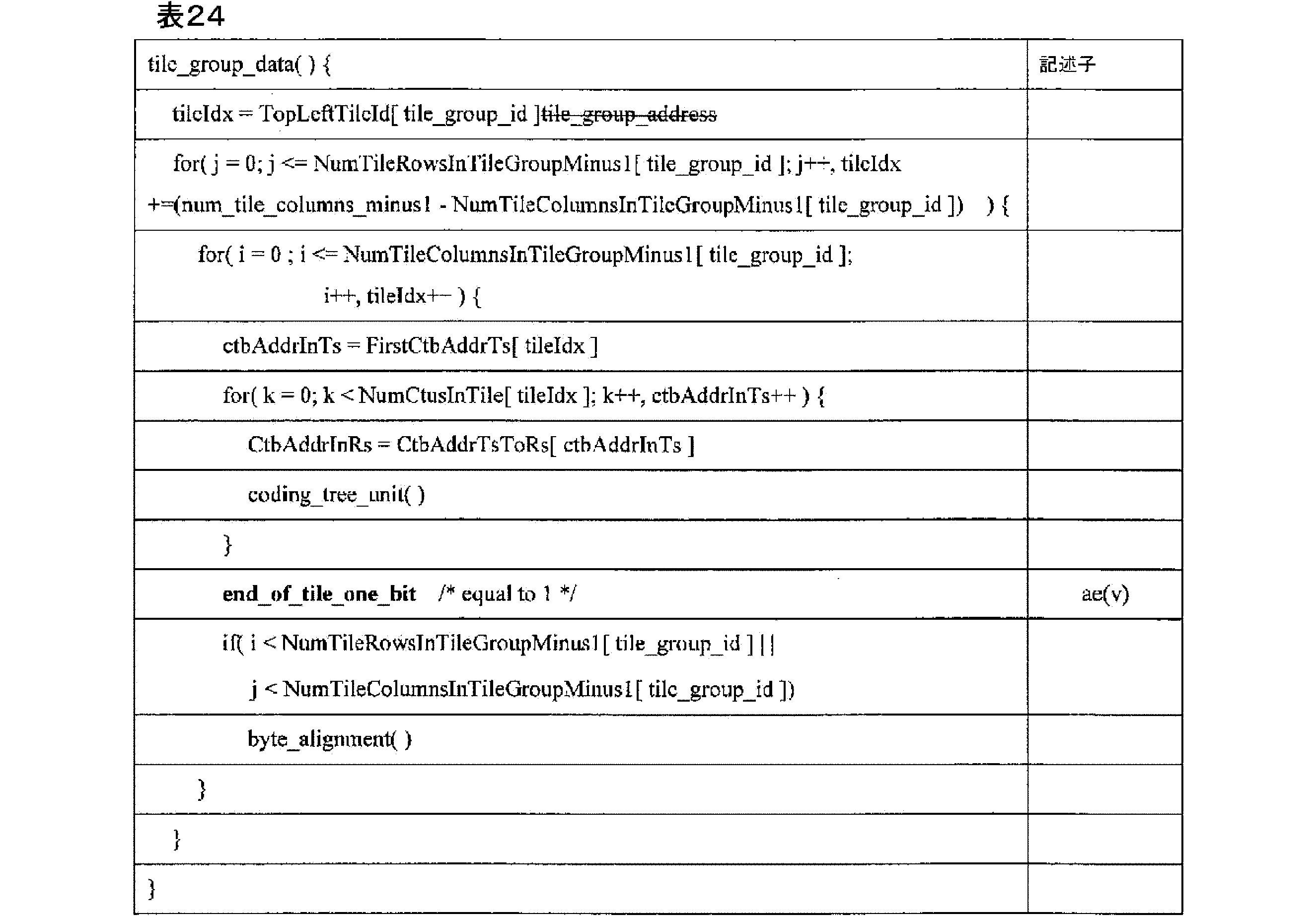
表23A、表23B、及び表24に関して、それぞれのシンタックス要素は、上記に提供されたセマンティクス及び定義並びに以下のセマンティクス及び定義に基づくことができる。 With respect to Table 23A, Table 23B, and Table 24, each syntax element may be based on the semantics and definitions provided above and the following semantics and definitions:
tile_group_idは、このタイルグループのタイルグループIDを指定する。Signalled_tile_group_index_flagが1に等しい場合、tile_group_idxシンタックス要素の長さは、signalled_tile_set_index_length_minus1+1ビットである。そうでなければ、tile_group_idxの長さは、Ceil(Log2(num_tile_groups_in_pic_minus1+1))ビットに等しい。 tile_group_id specifies the tile group ID for this tile group. If signalled_tile_group_index_flag is equal to 1, the length of the tile_group_idx syntax element is signalled_tile_set_index_length_minus1+1 bits. Otherwise, the length of tile_group_idx is equal to Ceil(Log2(num_tile_groups_in_pic_minus1+1)) bits.
別の実施例では、
tile_group_idは、このタイルグループのタイルグループIDを指定する。tile_group_idxシンタックス要素の長さは、signalled_tile_set_index_length_minus1+1ビットである。
In another embodiment,
tile_group_id specifies the tile group ID of this tile group. The length of the tile_group_idx syntax element is signalled_tile_set_index_length_minus1+1 bits.
offset_len_minus1プラス1は、entry_point_offset_minus1[i]シンタックス要素の長さ (ビット)を指定する。offset_len_minus1の値は、両端値を含む、0~31の範囲にあるもの
とする。
offset_len_minus1 plus 1 specifies the length (in bits) of the entry_point_offset_minus1[i] syntax element. The value of offset_len_minus1 shall be in the
entry_point_offset_minus1[i]プラス1は、i番目のエントリポイントオフセット(バイト)を指定し、offset_len_minus1プラス1ビットで表される。スライスヘッダに続くスライスデータは、rect_tile_group_flag?(NumTilesInTileGroup[tile_group_id]-1):num_tiles_in_tile_group_minus1+1サブセット、サブセットインデックス値は、0~rect_tile_group_flag?(NumTilesInTileGroup[tile_group_id]-1):num_tiles_in_tile_group_minus1(両端値を含む)。スライスデータの第1のバイトは、バイト0と見なされる。存在する場合、符号化スライスNALユニットのスライスデータ部分に現れるエミュレーション防止バイトは、サブセット識別の目的でスライスデータの一部としてカウントされる。サブセット0は、符号化スライスセグメントデータのバイト0~entry_point_offset_minus1[0](両端値を含む)からなり、サブセットkは、kが1~rect_tile_group_flag?(NumTilesInTileGroup [tile_group_id]-2):(num_tiles_in_tile_group_minus1-1)(両端値を含む)の範囲であり、符号化スライスデータのバイトfirstByte[k]~lastByte[k](両端値を含む)からなり、firstByte[k]及びlastByte[k]は、以下のとおり定義される。
entry_point_offset_minus1[i] plus 1 specifies the i-th entry point offset (in bytes), represented by offset_len_minus1 plus 1 bits. The slice data following the slice header is the rect_tile_group_flag?(NumTilesInTileGroup[tile_group_id]-1):num_tiles_in_tile_group_minus1+1 subset, with subset index values ranging from 0 to rect_tile_group_flag?(NumTilesInTileGroup[tile_group_id]-1):num_tiles_in_tile_group_minus1, inclusive. The first byte of the slice data is considered to be

最後のサブセット(サブセットインデックスがrect_tile_group_flag?(NumTilesInSliceNumTilesInTileGrpup[tile_groupset_idx]-1):num_tiles_in_tile_group_minus1に等しい)は、符号化スライスデータの残りのバイトからなる。 The final subset (subset index equal to rect_tile_group_flag?(NumTilesInSliceNumTilesInTileGrpup[tile_groupset_idx]-1):num_tiles_in_tile_group_minus1) consists of the remaining bytes of the coded slice data.
表22A~24に関して、一実施例では、CTBラスタ及びタイル走査プロセスは、以下のとおりであり得る。 With reference to Tables 22A-24, in one embodiment, the CTB raster and tile scanning process may be as follows:
CTBの単位で、i番目のタイル列の幅を指定する、両端値を含む、0~num_tile_columns_minus1の範囲のiについてのリストColWidth[i]は、以下のように導出される。
The list ColWidth[i], for i in the

CTBの単位で、j番目のタイル行の高さを指定する、両端値を含む、0~num_tile_rows_minus1の範囲のjについてのリストRowHeight[j]は、以下のように導出される。
The list RowHeight[j], for j in the

CTBの単位で、i番目のタイル列境界の場所を指定する、両端値を含む、0~num_tile_columns_minus1+1の範囲のiについてのリストColBd[i]は、以下のように導出される。
The list ColBd[i], for i in the

CTBの単位で、j番目のタイル行境界の場所を指定する、両端値を含む、0~num_tile_rows_minus1+1の範囲のjについてのリストRowBd[j]は、以下のように導出される。
The list RowBd[j], for j in the

ピクチャのCTBラスタ走査におけるCTBアドレスからタイル走査におけるCTBアドレスへの変換を指定する、両端値を含む、0~PicSizeInCtbsY-1の範囲のctbAddrRsであるリストCtbAddrRsToTs[ctbAddrRs]は、以下のように導出される。
The list CtbAddrRsToTs[ctbAddrRs], which is a set of ctbAddrRs in the

タイル走査におけるCTBアドレスからピクチャのCTBラスタ走査におけるCTBアドレスへの変換を指定する、両端値を含む、0~PicSizeInCtbsY-1の範囲のCtbAddrTsであるリストCtbAddrTsToRs[CtbAddrTs]は、以下のように導出される。
The list CtbAddrTsToRs[CtbAddrTs], which is a set of CtbAddrTs in the

タイル走査におけるCTBアドレスからタイルIDへの変換を指定する、両端値を含む、0~PicSizeInCtbsY-1の範囲のCtbAddrTsであるリストTileId[ctbAddrTs]は、以下のように導出される。
The list TileId[ctbAddrTs], which is a set of CtbAddrTs in the

タイルにおけるタイルインデックスからCTUの数への変換を指定する、両端値を含む、0~PicSizeInCtbsY-1の範囲のtileIdxであるリストNumCtusInTile[tileIdx]は、以下のように導出される。
The list NumCtusInTile[tileIdx], which is a tileIdx in the

タイルIDからタイルインデックスへの変換を指定するNumTilesInPic tileId値のセットについてのセット[TileIdToIdx[tileId]、及びタイル内の第1のCTBのタイル走査におけるタイルIDからCTBアドレスへの変換を指定する、両端値を含む、0~NumTilesInPic1の範囲のtileIdxについてのリストFirstCtbAddrTs[tileIdx]は、以下のように導出される。
The set [TileIdToIdx[tileId] for the set of NumTilesInPic tileId values that specifies the conversion from tile ID to tile index, and the list FirstCtbAddrTs[tileIdx] for tileIdx in the


ルマサンプルの単位で、i番目のタイル列の幅を指定する、ColumnWidthInLumaSamples[i]の値は、両端値を含む、0~num_tile_columns_minus1の範囲のiについてColWidth[i]<<
CtbLog2SizeYに等しく設定される。
Specifies the width of the i-th tile column, in units of luma samples. The value of ColumnWidthInLumaSamples[i] is in the
Set equal to CtbLog2SizeY.
ルマサンプルの単位で、j番目のタイル行の高さを指定する、RowHeightInLumaSamples[j]の値は、両端値を含む、0~num_tile_rows_minus1の範囲のjについてRowHeight[j]<<CtbLog2SizeYに等しく設定される。
The value of RowHeightInLumaSamples[j], which specifies the height of the jth tile row in units of luma samples, is set equal to RowHeight[j]<<CtbLog2SizeY for j in the
このようにして、ソースデバイス102は、タイルセットがビットストリームで有効になっていることを示すフラグをシグナリングし、ピクチャを区画する数タイルセット列を示すシンタックス要素をシグナリングし、ピクチャを区画する数タイルセット行を示すシンタックス要素をシグナリングするように構成されたデバイスの例を表す。 In this manner, source device 102 represents an example of a device configured to signal a flag indicating that a tile set is enabled in the bitstream, signal a syntax element indicating how many tile set columns a picture is partitioned by, and signal a syntax element indicating how many tile set rows a picture is partitioned by.
図1を再び参照すると、インターフェース108は、データカプセル化部107によって生成されたデータを受信し、そのデータを通信媒体に送信及び/又は記憶するように構成された任意のデバイスを含んでもよい。インターフェース108は、イーサネットカードなどのネットワークインターフェースカードを含むことができ、光送受信機、無線周波数送受信機、又は情報を送信及び/若しくは受信することができる任意の他の種類のデバイスを含むことができる。更に、インターフェース108は、ファイルを記憶デバイス上に記憶することを可能にすることができるコンピュータシステムインターフェースを含むことができる。例えば、インターフェース108は、Peripheral Component Interconnect(PCI)及びPeripheral Component Interconnect Express(PCIe)バスプロトコル、独自のバスプロトコル、ユニバーサルシリアルバス(Universal Serial Bus、USB)プロトコル、I2C、又はピアデバイスを相互接続するために使用することができる任意の他の論理構造及び物理構造をサポートする、チップセットを含むことができる。 Referring again to FIG. 1, interface 108 may include any device configured to receive data generated by data encapsulator 107 and transmit and/or store the data on a communication medium. Interface 108 may include a network interface card, such as an Ethernet card, and may include an optical transceiver, a radio frequency transceiver, or any other type of device capable of transmitting and/or receiving information. Additionally, interface 108 may include a computer system interface that may allow files to be stored on a storage device. For example, interface 108 may include a chipset that supports Peripheral Component Interconnect (PCI) and Peripheral Component Interconnect Express (PCIe) bus protocols, a proprietary bus protocol, a Universal Serial Bus (USB) protocol, I2C , or any other logical and physical structure that may be used to interconnect peer devices.
図1を再び参照すると、目的デバイス120は、インターフェース122と、データデカプセル化部123と、ビデオデコーダ124と、ディスプレイ126とを含む。インターフェース122は、通信媒体からデータ受信するように構成されている任意のデバイスを含むことができる。インターフェース122は、イーサネットカードなどのネットワークインターフェースカードを含むことができ、光送受信機、無線周波数送受信機、又は情報を受信及び/若しくは送信することができる任意の他の種類のデバイスを含むことができる。更に、インターフェース122は、準拠ビデオビットストリームを記憶デバイスから取得することを可能にするコンピュータシステム用インターフェースを含むことができる。例えば、インターフェース122は、PCI及びPCIeバスプロトコル、独自のバスプロトコル、USBプロトコル、I2C、又はピアデバイスを相互接続するために使用することができる任意の他の論理構造及び物理構造をサポートする、チップセットを含むことができる。データデカプセル化部123は、本明細書に記載される例示的なパラメータセットのうちのいずれかを受信及び解析するように構成されてもよい。
Referring again to FIG. 1, the destination device 120 includes an
ビデオ復号器124は、ビットストリーム(例えば、MCTSサブビットストリーム抽出)及び/又はその許容可能な変形を受信し、そこからビデオデータを再生成するように構成されている任意のデバイスを含むことができる。ディスプレイ126は、ビデオデータを表示するように構成された任意のデバイスを含むことができる。ディスプレイ126は、液晶ディスプレイ(liquid crystal display、LCD)、プラズマディスプレイ、有機発光ダイオード(organic light emitting diode、OLED)ディスプレイ、又は別の種類のディスプレイなどの、様々なディスプレイデバイスのうちの1つを含むことができる。ディスプレイ126は、高解像度ディスプレイ又は超高解像度ディスプレイを含むことができる。図1に示す例では、ビデオデコーダ124は、データをディスプレイ126に出力するように説明されているが、ビデオデコーダ124は、ビデオデータを様々な種類のデバイス及び/又はそのサブコンポーネントに出力するように構成することができることに留意されたい。例えば、ビデオデコーダ124は、本明細書で説明するような任意の通信媒体にビデオデータを出力するように構成することができる。 The video decoder 124 may include any device configured to receive a bitstream (e.g., an MCTS sub-bitstream extract) and/or an acceptable variant thereof and regenerate video data therefrom. The display 126 may include any device configured to display video data. The display 126 may include one of a variety of display devices, such as a liquid crystal display (LCD), a plasma display, an organic light emitting diode (OLED) display, or another type of display. The display 126 may include a high-definition display or an ultra-high-definition display. In the example shown in FIG. 1, the video decoder 124 is described as outputting data to the display 126, but it should be noted that the video decoder 124 may be configured to output video data to various types of devices and/or subcomponents thereof. For example, the video decoder 124 may be configured to output video data to any communication medium as described herein.
図9は、本開示の1つ以上の技術による、ビデオデータを復号するように構成することができるビデオデコーダの一例を示すブロック図である。一実施例では、ビデオデコーダ600は、変換データを復号し、復号された変換データに基づいて変換係数から残差データを復元するように構成することができる。ビデオデコーダ600は、イントラ予測復号及びインター予測復号を実行するように構成される場合があり、そのために、ハイブリッドデコーダと称される場合がある。図9に示す例では、ビデオデコーダ600は、エントロピ復号部602、逆量子化部及び変換係数処理部604、イントラ予測処理部606、インター予測処理部608、加算部610、ポストフィルタ部612、並びに参照バッファ614を含む。ビデオデコーダ600は、ビデオ符号化システムと合致するようにしてビデオデータを復号するように構成することができる。例のビデオデコーダ600が別個の機能ブロックを有するように示されているが、そのような例示は説明のためのものであり、ビデオデコーダ600及び/又はその下位構成要素を特定のハードウェア又はソフトウェアアーキテクチャに限定するものではないことに留意されたい。ビデオデコーダ600の機能は、ハードウェア、ファームウェア、及び/又はソフトウェアの実装形態の任意の組み合わせを用いて実現することができる。 FIG. 9 is a block diagram illustrating an example of a video decoder that may be configured to decode video data in accordance with one or more techniques of the present disclosure. In one embodiment, the video decoder 600 may be configured to decode transform data and recover residual data from transform coefficients based on the decoded transform data. The video decoder 600 may be configured to perform intra-prediction and inter-prediction decoding, and may therefore be referred to as a hybrid decoder. In the example illustrated in FIG. 9, the video decoder 600 includes an entropy decoder 602, an inverse quantizer and transform coefficient processor 604, an intra-prediction processor 606, an inter-prediction processor 608, an adder 610, a postfilter 612, and a reference buffer 614. The video decoder 600 may be configured to decode video data in a manner consistent with a video encoding system. It should be noted that, although the example video decoder 600 is illustrated as having separate functional blocks, such illustration is for purposes of explanation and is not intended to limit the video decoder 600 and/or its subcomponents to a particular hardware or software architecture. The functionality of the video decoder 600 can be realized using any combination of hardware, firmware, and/or software implementations.
図9に示すように、エントロピ復号部602は、エントロピ符号化されたビットストリームを受信する。エントロピ復号部602は、エントロピ符号化プロセスとは逆の(reciprocal)プロセスに従って、ビットストリームからシンタックス要素及び量子化された係数を復号するように構成することができる。エントロピ復号部602は、上述したエントロピ符号化技術のいずれかに従ってエントロピ復号を実行するように構成することができる。エントロピ復号部602は、ビデオ符号化規格と合致するようにして、符号化されたビットストリーム中のシンタックス要素の値を判定することができる。図9に示すように、エントロピ復号部602は、ビットストリームから量子化パラメータ、量子化された係数の値、変換データ、及び予測データを判定することができる。図9に示す実施例では、逆量子化部及び変換係数処理部604は、量子化パラメータ、量子化された係数の値、変換データ、及び予測データをエントロピ復号部602から受信し、復元された残差データを出力する。 As shown in FIG. 9, the entropy decoding unit 602 receives an entropy coded bitstream. The entropy decoding unit 602 may be configured to decode syntax elements and quantized coefficients from the bitstream according to a reciprocal process of the entropy coding process. The entropy decoding unit 602 may be configured to perform entropy decoding according to any of the entropy coding techniques described above. The entropy decoding unit 602 may determine values of syntax elements in the coded bitstream in accordance with a video coding standard. As shown in FIG. 9, the entropy decoding unit 602 may determine quantization parameters, quantized coefficient values, transform data, and prediction data from the bitstream. In the embodiment shown in FIG. 9, the inverse quantization and transform coefficient processing unit 604 receives the quantization parameters, quantized coefficient values, transform data, and prediction data from the entropy decoding unit 602 and outputs reconstructed residual data.
図9を再び参照すると、復元された残差データが加算部610に提供されてもよく、加算部610は、復元された残差データを予測ビデオブロックに追加し、復元されたビデオデータを生成することができる。予測ビデオブロックは、予測ビデオ技術(すなわち、イントラ予測及びフレーム間予測)に従って判定することができる。イントラ予測処理部606は、イントラ予測シンタックス要素を受信し、参照バッファ614から予測ビデオブロックを取得するように構成することができる。参照バッファ614は、ビデオデータの1つ以上のフレームを記憶するように構成されたメモリデバイスを含むことができる。イントラ予測シンタックス要素は、上述したイントラ予測モードなどのイントラ予測モードを識別することができる。インター予測処理部608は、インター予測シンタックス要素を受信し、動きベクトルを生成して、参照バッファ814に記憶された1つ以上の参照フレーム内の予測ブロックを識別することができる。インター予測処理部608は、場合によっては補間フィルタに基づく補間を実行して、動き補償されたブロックを生成することができる。シンタックス要素には、画素未満の精度を有する動き予測に使用されることになる補間フィルタの識別子を含めることができる。インター予測処理部808は、補間フィルタを使用して、参照ブロックのサブ整数の画素に対する補間された値を算出することができる。ポストフィルタ部612は、復元されたビデオデータに対してフィルタリングを実行するように構成することができる。例えば、ポストフィルタ部612は、例えば、ビットストリームで規定されたパラメータに基づいて、デブロッキング及び/又はサンプル適応オフセット(SAO)フィルタリングを実行するように構成することができる。更に、いくつかの例では、ポストフィルタ部612は、独自の任意フィルタリング(例えば、モスキートノイズリダクションなどの視覚強調)を実行するように構成することができることに留意されたい。図9に示すように、復元されたビデオブロックは、ビデオデコーダ600によって出力することができる。このようにして、ビデオデコーダ600は、タイルセットがビットストリームで有効になっていることを示すフラグをパースし、ピクチャを区画する数タイルセット列を示すシンタックス要素をパースし、ピクチャを区画する数タイルセット行を示すシンタックス要素をパースし、パースされたシンタックス要素の値に基づいてビデオデータを生成するように構成され得る。 Referring again to FIG. 9, the reconstructed residual data may be provided to the adder 610, which may add the reconstructed residual data to a predictive video block to generate reconstructed video data. The predictive video block may be determined according to a predictive video technique (i.e., intra prediction and inter-frame prediction). The intra prediction processor 606 may be configured to receive the intra prediction syntax element and obtain the predictive video block from the reference buffer 614. The reference buffer 614 may include a memory device configured to store one or more frames of video data. The intra prediction syntax element may identify an intra prediction mode, such as the intra prediction modes described above. The inter prediction processor 608 may receive the inter prediction syntax element and generate a motion vector to identify a predictive block in one or more reference frames stored in the reference buffer 814. The inter prediction processor 608 may optionally perform interpolation based on an interpolation filter to generate a motion compensated block. The syntax element may include an identifier of an interpolation filter to be used for motion prediction having sub-pixel accuracy. The inter prediction processor 808 may use an interpolation filter to calculate interpolated values for sub-integer pixels of the reference block. The post filter unit 612 may be configured to perform filtering on the restored video data. For example, the post filter unit 612 may be configured to perform deblocking and/or sample adaptive offset (SAO) filtering, for example, based on parameters specified in the bitstream. It should be noted that in some examples, the post filter unit 612 may also be configured to perform custom optional filtering (e.g., visual enhancement such as mosquito noise reduction). As shown in FIG. 9, the restored video blocks may be output by the video decoder 600. In this manner, the video decoder 600 may be configured to parse a flag indicating that a tile set is enabled in the bitstream, parse a syntax element indicating a number of tile set columns that partition the picture, parse a syntax element indicating a number of tile set rows that partition the picture, and generate video data based on the values of the parsed syntax elements.
1つ以上の例では、記載された機能は、ハードウェア、ソフトウェア、ファームウェア、又はこれらの任意の組み合わせで実装することができる。ソフトウェアで実装される場合に、この機能は、コンピュータ可読媒体上の1つ以上の命令又はコードとして記憶するか又は伝送され、ハードウェアベースの処理部によって実行することができる。コンピュータ可読媒体は、例えば、通信プロトコルに従って、ある場所から別の場所へのコンピュータプログラムの転送を容易にする任意の媒体を含む、データ記憶媒体又は通信媒体などの有形の媒体に対応する、コンピュータ可読記憶媒体を含むことができる。このようにして、コンピュータ可読媒体は、一般に、(1)非一時的な有形のコンピュータ可読記憶媒体、又は(2)信号又は搬送波などの通信媒体に対応することができる。データ記憶媒体は、本開示中に記載された技術の実現のための命令、コード、及び/又はデータ構造を取り出すために、1つ以上のコンピュータ又は1つ以上のプロセッサによってアクセスされ得る任意の利用可能な媒体であり得る。コンピュータプログラム製品は、コンピュータ可読媒体を含むことができる。 In one or more examples, the functions described may be implemented in hardware, software, firmware, or any combination thereof. When implemented in software, the functions may be stored or transmitted as one or more instructions or code on a computer-readable medium and executed by a hardware-based processing unit. A computer-readable medium may include a computer-readable storage medium, which corresponds to a tangible medium such as a data storage medium or a communication medium, including any medium that facilitates the transfer of a computer program from one place to another according to a communication protocol, for example. In this manner, a computer-readable medium may generally correspond to (1) a non-transitory tangible computer-readable storage medium, or (2) a communication medium such as a signal or carrier wave. A data storage medium may be any available medium that may be accessed by one or more computers or one or more processors to retrieve instructions, code, and/or data structures for implementation of the techniques described in this disclosure. A computer program product may include a computer-readable medium.
一例として、非限定的に、このようなコンピュータ可読記憶媒体は、RAM、ROM、EEPROM、CD-ROM、又は他の光学ディスク記憶装置、磁気ディスク記憶装置、他の磁気記憶装置、フラッシュメモリ、又は任意の他の媒体、すなわち命令若しくはデータ構造の形式で所望のプログラムコードを記憶するために使用可能であり、かつコンピュータによりアクセス可能な任意の他の媒体を含むことができる。また、任意の接続は、コンピュータ可読媒体と適切に呼ばれる。例えば、命令がウェブサイト、サーバ、又は他のリモートソースから、同軸ケーブル、光ファイバケーブル、ツイストペア、デジタル加入者線(digital subscriber line、DSL)、あるいは赤外線、無線及びマイクロ波などの無線技術を使用して伝送される場合、同軸ケーブル、光ファイバケーブル、ツイストペア、DSL、あるいは赤外線、無線及びマイクロ波などの無線技術は、媒体の定義に含まれる。しかし、コンピュータ可読媒体及びデータ記憶媒体は、接続、搬送波、信号、又は他の一過性媒体を含まないが、代わりに非一時的な有形記憶媒体を対象としていることを理解されたい。本発明で使用する場合、ディスク(disk)及びディスク(disc)は、コンパクトディスク(Compact Disc、CD)、レーザーディスク(laser disc)、光学ディスク(optical disc)、デジタル多用途ディスク(Digital Versatile Disc、DVD)、フロッピーディスク(floppy disk)及びブルーレイ (登録商標)ディスク(Blu-ray(登録商標)disc)を含み、ディスク(disk)は通常データを磁気的に再生し、ディスク(disc)はレーザを用いてデータを光学的に再生する。上記の組み合わせもまた、コンピュータ可読媒体の範囲内に含まれなければならない。 By way of example, and without limitation, such computer-readable storage media may include RAM, ROM, EEPROM, CD-ROM, or other optical disk storage, magnetic disk storage, other magnetic storage, flash memory, or any other medium, i.e., any other medium usable to store desired program code in the form of instructions or data structures and accessible by a computer. Also, any connection is properly referred to as a computer-readable medium. For example, if instructions are transmitted from a website, server, or other remote source using coaxial cable, fiber optic cable, twisted pair, digital subscriber line (DSL), or wireless technologies such as infrared, radio, and microwave, the coaxial cable, fiber optic cable, twisted pair, DSL, or wireless technologies such as infrared, radio, and microwave are included in the definition of the medium. However, it should be understood that computer-readable media and data storage media do not include connections, carrier waves, signals, or other transitory media, but are instead directed to non-transitory tangible storage media. As used herein, disk and disc include compact disc (CD), laser disc, optical disc, digital versatile disc (DVD), floppy disk and Blu-ray disc, where disks typically reproduce data magnetically and discs reproduce data optically using a laser. Combinations of the above should also be included within the scope of computer readable media.
命令は、1つ以上のデジタル信号プロセッサ(DSP)、汎用マイクロプロセッサ、特定用途向け集積回路(ASIC)、フィールドプログラマブルゲート配列(FPGA)、又は他の同等の集積又はディスクリートロジック回路などの1つ以上のプロセッサによって実行することができる。したがって、本明細書で使用されるとき、用語「プロセッサ」は、前記の構造、又は本明細書で説明する技術の実装に好適な任意の他の構造のいずれかを指すことができる。加えて、いくつかの態様において、本明細書に記載の機能は、符号化及び復号化するように構成された、又は複合コーデックに組み込まれた専用のハードウェアモジュール及び/又はソフトウェアモジュール内に設けられ得る。また、この技術は、1つ以上の回路又は論理素子中に完全に実装することができる。 The instructions may be executed by one or more processors, such as one or more digital signal processors (DSPs), general-purpose microprocessors, application specific integrated circuits (ASICs), field programmable gate arrays (FPGAs), or other equivalent integrated or discrete logic circuits. Thus, as used herein, the term "processor" may refer to any of the foregoing structures, or any other structure suitable for implementing the techniques described herein. Additionally, in some aspects, the functionality described herein may be provided in dedicated hardware and/or software modules configured to encode and decode, or incorporated into a composite codec. Also, the techniques may be implemented entirely in one or more circuit or logic elements.
本開示の技術は、無線ハンドセット、集積回路(integrated circuit、IC)、又はICのセット(例えば、チップセット)を含む多種多様なデバイス又は装置に実装することができる。様々なコンポーネント、モジュール、又はユニットを本開示中に示し、開示された技術を実行するように構成されたデバイスの機能的な態様を強調しているが、異なるハードウェアユニットによって実現することは必ずしも必要ではない。むしろ、前述したように、様々なユニットは、コーデックハードウェアユニットに組み合わせてもよく、又は好適なソフトウェア及び/又はファームウェアと共に、前述の1つ以上のプロセッサを含む、相互動作ハードウェアユニットの集合によって提供することができる。 The techniques of this disclosure may be implemented in a wide variety of devices or apparatuses, including wireless handsets, integrated circuits (ICs), or sets of ICs (e.g., chipsets). Various components, modules, or units are illustrated in this disclosure to highlight functional aspects of devices configured to perform the disclosed techniques, but need not necessarily be realized by different hardware units. Rather, as previously described, the various units may be combined into a codec hardware unit or may be provided by a collection of interoperating hardware units, including one or more processors as previously described, along with suitable software and/or firmware.
更に、上述の各実装形態で用いた基地局装置や端末装置の各機能ブロックや各種の機能は、一般的には集積回路又は複数の集積回路である電気回路によって実現又は実行することができる。本明細書に記載の機能を実行するように設計された回路は、汎用プロセッサ、デジタル信号プロセッサ(DSP)、特定用途向け又は汎用アプリケーション集積回路(ASIC)、フィールドプログラマブルゲート配列(FPGA)若しくは他のプログラマブルロジックデバイス、ディスクリートゲート若しくはトランジスタロジック、若しくは個々のハードウェアコンポーネント、又はそれらの組み合わせを備えていてもよい。汎用プロセッサは、マイクロプロセッサでもよく、あるいは、プロセッサは、従来のプロセッサ、コントローラ、マイクロコントローラ、又はステートマシンでもよい。上述した汎用プロセッサ又は各回路は、デジタル回路で構成されても、又はアナログ回路で構成されてもよい。更に、半導体技術の進歩により現時点での集積回路に置き換わる集積回路化技術が現れれば、この技術による集積回路もまた使用可能となる。 Furthermore, each functional block and various functions of the base station device and terminal device used in each of the above-mentioned implementations can be realized or performed by an electric circuit, which is generally an integrated circuit or a plurality of integrated circuits. The circuit designed to perform the functions described herein may comprise a general-purpose processor, a digital signal processor (DSP), an application specific or general-purpose integrated circuit (ASIC), a field programmable gate array (FPGA) or other programmable logic device, discrete gate or transistor logic, or individual hardware components, or a combination thereof. The general-purpose processor may be a microprocessor, or the processor may be a conventional processor, controller, microcontroller, or state machine. The general-purpose processor or each circuit described above may be composed of digital circuits or analog circuits. Furthermore, if an integrated circuit technology emerges that replaces the current integrated circuits due to the progress of semiconductor technology, the integrated circuits using this technology may also be used.
様々な実施例について説明した。これら及び他の実施例は、以下の特許請求の範囲内である。 Various implementations have been described. These and other implementations are within the scope of the following claims.
<相互参照>
WO2020/111023号公報として公開された国際出願PCT/JP2019/046062(2019年11月26日出願)に基づく国内出願である本願は、米国特許仮出願第62/774,050号(2018年11月30日出願)、第62/784,296号(2018年12月21日出願)、第62/791,227号(2019年1月11日出願)、第62/806,502号(2019年2月15日出願)に基づく優先権を主張するものであり、その内容の全体が参照により本明細書に組み込まれる。
<Cross reference>
This application, which is a domestic application based on International Application PCT/JP2019/046062 (filed November 26, 2019), published as WO2020/111023, claims priority to U.S. Provisional Application Nos. 62/774,050 (filed November 30, 2018), 62/784,296 (filed December 21, 2018), 62/791,227 (filed January 11, 2019), and 62/806,502 (filed February 15, 2019), the contents of which are incorporated herein by reference in their entireties.
Claims (10)
パラメータセット内の第1のフラグシンタックスを復号することであって、前記第1のフラグシンタックスは、値が第1の所定の値と等しい場合、少なくとも1つのスライスの各々におけるタイルがラスタ走査順であることを指定し、値が前記第1の所定の値と異なる場合、前記少なくとも1つのスライスの各々におけるタイルがピクチャの矩形領域をカバーすることを指定する、復号することと、
前記第1のフラグシンタックスの前記値が前記第1の所定の値と異なる場合、前記パラメータセット内に存在するナンバーシンタックスであって、前記ピクチャ内のスライスの数を指定する第1のナンバーシンタックスを復号することと、
前記第1のフラグシンタックスの前記値が前記第1の所定の値と等しい場合、スライスアドレスシンタックス、およびスライスヘッダに存在するナンバーシンタックスであって、スライスに含まれるタイルの数を指定する第2のナンバーシンタックスを復号することと、
を含む、方法。 1. A method for decoding video data, comprising the steps of:
decoding a first flag syntax in a parameter set that, when a value is equal to a first predetermined value, specifies that the tiles in each of at least one slice are in raster scan order, and when a value is different from the first predetermined value, specifies that the tiles in each of the at least one slice cover a rectangular region of the picture;
if the value of the first flag syntax is different from the first predetermined value, decoding a first number syntax present in the parameter set, the first number syntax specifying a number of slices in the picture;
if the value of the first flag syntax is equal to the first predetermined value, decoding a slice address syntax and a second number syntax present in a slice header, the second number syntax specifying a number of tiles included in the slice;
A method comprising:
請求項1に記載の方法。 the slice address syntax is present in the slice header if a value of the first flag syntax specifies that the tiles in each of the at least one slice are in raster scan order and the number of tiles in the picture corresponding to the slice header is greater than one.
The method of claim 1.
請求項1に記載の方法。 a value of the first number syntax plus one specifies a number of slices in each of at least one picture corresponding to the parameter set;
The method of claim 1.
請求項1に記載の方法。 a value of the second number syntax plus one specifies the number of tiles in each of the at least one slice corresponding to the slice header;
The method of claim 1.
少なくとも1つのプロセッサと、
前記少なくとも1つのプロセッサに結合された記憶デバイスであって、前記少なくとも1つのプロセッサによって実行され、前記少なくとも1つのプロセッサに請求項1から4の何れかに記載の方法を実行させるプログラムを格納する記憶デバイスと、
を備えるデバイス。 1. A device for decoding video data, comprising:
At least one processor;
a storage device coupled to said at least one processor, said storage device storing a program that, when executed by said at least one processor, causes said at least one processor to perform the method according to any one of claims 1 to 4;
16. A device comprising:
パラメータセット内の第1のフラグシンタックスるを符号化することであって、前記第1のフラグシンタックスは、値が第1の所定の値と等しい場合、少なくとも1つのスライスの各々におけるタイルがラスタ走査順であることを指定し、値が前記第1の所定の値と異なる場合、前記少なくとも1つのスライスの各々におけるタイルがピクチャの矩形領域をカバーすることを指定する、符号化することと、
前記第1のフラグシンタックスの前記値が前記第1の所定の値と異なる場合、前記パラメータセット内に存在するナンバーシンタックスであって、前記ピクチャ内のスライスの数を指定する第1のナンバーシンタックスを符号化することと、
前記第1のフラグシンタックスの前記値が前記第1の所定の値と等しい場合、スライスアドレスシンタックス、およびスライスヘッダに存在するナンバーシンタックスであって、スライスに含まれるタイルの数を指定する第2のナンバーシンタックスを符号化することと、
を含む方法。 1. A method for encoding video data, comprising the steps of:
encoding a first flag syntax in a parameter set that, when a value is equal to a first predetermined value, specifies that the tiles in each of at least one slice are in raster scan order, and, when a value is different from the first predetermined value, specifies that the tiles in each of the at least one slice cover a rectangular region of the picture;
if the value of the first flag syntax is different from the first predetermined value, encoding a first number syntax present in the parameter set, the first number syntax specifying a number of slices in the picture;
if the value of the first flag syntax is equal to the first predetermined value, encoding a slice address syntax and a second number syntax present in a slice header, the second number syntax specifying a number of tiles included in the slice;
The method includes:
請求項6に記載の方法。 the slice address syntax is present in the slice header if a value of the first flag syntax specifies that the tiles in each of the at least one slice are in raster scan order and the number of tiles in the picture corresponding to the slice header is greater than one.
The method according to claim 6.
請求項6に記載の方法。 a value of the first number syntax plus one specifies a number of slices in each of at least one picture corresponding to the parameter set;
The method according to claim 6.
請求項6に記載の方法。 a value of the second number syntax plus one specifies the number of tiles in each of the at least one slice corresponding to the slice header;
The method according to claim 6.
少なくとも1つのプロセッサと、
前記少なくとも1つのプロセッサに結合された記憶デバイスであって、前記少なくとも1つのプロセッサによって実行され、前記少なくとも1つのプロセッサに請求項6から9の何れかに記載の方法を実行させるプログラムを格納する記憶デバイスと、
を備えるデバイス。 1. A device for encoding video data, comprising:
At least one processor;
a storage device coupled to said at least one processor, said storage device storing a program that, when executed by said at least one processor, causes said at least one processor to perform a method according to any one of claims 6 to 9;
16. A device comprising:
Applications Claiming Priority (11)
| Application Number | Priority Date | Filing Date | Title |
|---|---|---|---|
| US201862774050P | 2018-11-30 | 2018-11-30 | |
| US62/774,050 | 2018-11-30 | ||
| US201862784296P | 2018-12-21 | 2018-12-21 | |
| US62/784,296 | 2018-12-21 | ||
| US201962791227P | 2019-01-11 | 2019-01-11 | |
| US62/791,227 | 2019-01-11 | ||
| US201962806502P | 2019-02-15 | 2019-02-15 | |
| US62/806,502 | 2019-02-15 | ||
| PCT/JP2019/046062 WO2020111023A1 (en) | 2018-11-30 | 2019-11-26 | Systems and methods for signaling tile structures for pictures of coded video |
| JP2021529357A JP7307168B2 (en) | 2018-11-30 | 2019-11-26 | Systems and methods for signaling tile structures for pictures of encoded video |
| JP2023107242A JP7521077B2 (en) | 2018-11-30 | 2023-06-29 | System and method for signaling tile structure for coded video pictures - Patents.com |
Related Parent Applications (1)
| Application Number | Title | Priority Date | Filing Date |
|---|---|---|---|
| JP2023107242A Division JP7521077B2 (en) | 2018-11-30 | 2023-06-29 | System and method for signaling tile structure for coded video pictures - Patents.com |
Publications (2)
| Publication Number | Publication Date |
|---|---|
| JP2024138411A JP2024138411A (en) | 2024-10-08 |
| JP7699699B2 true JP7699699B2 (en) | 2025-06-27 |
Family
ID=70852305
Family Applications (3)
| Application Number | Title | Priority Date | Filing Date |
|---|---|---|---|
| JP2021529357A Active JP7307168B2 (en) | 2018-11-30 | 2019-11-26 | Systems and methods for signaling tile structures for pictures of encoded video |
| JP2023107242A Active JP7521077B2 (en) | 2018-11-30 | 2023-06-29 | System and method for signaling tile structure for coded video pictures - Patents.com |
| JP2024110897A Active JP7699699B2 (en) | 2018-11-30 | 2024-07-10 | System and method for signaling tile structure for coded video pictures - Patents.com |
Family Applications Before (2)
| Application Number | Title | Priority Date | Filing Date |
|---|---|---|---|
| JP2021529357A Active JP7307168B2 (en) | 2018-11-30 | 2019-11-26 | Systems and methods for signaling tile structures for pictures of encoded video |
| JP2023107242A Active JP7521077B2 (en) | 2018-11-30 | 2023-06-29 | System and method for signaling tile structure for coded video pictures - Patents.com |
Country Status (9)
| Country | Link |
|---|---|
| US (2) | US12167012B2 (en) |
| EP (1) | EP3888372A4 (en) |
| JP (3) | JP7307168B2 (en) |
| KR (1) | KR102572140B1 (en) |
| CN (2) | CN118118693A (en) |
| BR (1) | BR112021010326A2 (en) |
| MX (1) | MX2021006218A (en) |
| PH (1) | PH12021551147A1 (en) |
| WO (1) | WO2020111023A1 (en) |
Families Citing this family (15)
| Publication number | Priority date | Publication date | Assignee | Title |
|---|---|---|---|---|
| EP3855740A4 (en) * | 2018-09-19 | 2022-09-28 | Electronics and Telecommunications Research Institute | METHOD AND APPARATUS FOR CODING/DECODING IMAGES, AND RECORDING MEDIA STORING A BITSTREAM |
| WO2020111023A1 (en) * | 2018-11-30 | 2020-06-04 | Sharp Kabushiki Kaisha | Systems and methods for signaling tile structures for pictures of coded video |
| BR112021011413A2 (en) * | 2018-12-17 | 2021-08-31 | Huawei Technologies Co., Ltd. | VIDEO CODING METHOD AND APPARATUS |
| US12113997B2 (en) * | 2019-01-22 | 2024-10-08 | Tencent America LLC | Method for tile group identification |
| CN113508583B (en) * | 2019-03-04 | 2024-08-27 | Lg电子株式会社 | Video or image coding based on intra-frame block coding |
| JP7448349B2 (en) * | 2019-12-17 | 2024-03-12 | シャープ株式会社 | Video decoding device |
| JP7460784B2 (en) | 2020-02-21 | 2024-04-02 | 北京字節跳動網絡技術有限公司 | Coding pictures with slices and tiles |
| KR20260023606A (en) | 2020-02-21 | 2026-02-20 | 두인 비전 컴퍼니 리미티드 | Slice and tile partitioning in video coding |
| WO2021185311A1 (en) * | 2020-03-20 | 2021-09-23 | Mediatek Inc. | Method and apparatus for signaling tile and slice partition information in image and video coding |
| CN115606184B (en) | 2020-04-01 | 2026-01-30 | 抖音视界有限公司 | Control of signaling notification for quantization parameter increments |
| CN115699742A (en) | 2020-04-07 | 2023-02-03 | 抖音视界有限公司 | Signaling and inference of subpicture related syntax elements |
| WO2021204233A1 (en) | 2020-04-09 | 2021-10-14 | Beijing Bytedance Network Technology Co., Ltd. | Constraints on adaptation parameter set based on color format |
| WO2021204251A1 (en) | 2020-04-10 | 2021-10-14 | Beijing Bytedance Network Technology Co., Ltd. | Use of header syntax elements and adaptation parameter set |
| CN115868159A (en) | 2020-04-17 | 2023-03-28 | 抖音视界有限公司 | Presence of Adaptive Parameter Set Units |
| CN115552802B (en) | 2020-04-26 | 2025-05-16 | 字节跳动有限公司 | Conditional signaling of weighted prediction information |
Citations (1)
| Publication number | Priority date | Publication date | Assignee | Title |
|---|---|---|---|---|
| JP7307168B2 (en) | 2018-11-30 | 2023-07-11 | シャープ株式会社 | Systems and methods for signaling tile structures for pictures of encoded video |
Family Cites Families (15)
| Publication number | Priority date | Publication date | Assignee | Title |
|---|---|---|---|---|
| WO2014047134A1 (en) * | 2012-09-18 | 2014-03-27 | Vid Scale, Inc. | Region of interest video coding using tiles and tile groups |
| US11438609B2 (en) * | 2013-04-08 | 2022-09-06 | Qualcomm Incorporated | Inter-layer picture signaling and related processes |
| US9749627B2 (en) * | 2013-04-08 | 2017-08-29 | Microsoft Technology Licensing, Llc | Control data for motion-constrained tile set |
| US9936207B2 (en) * | 2013-10-14 | 2018-04-03 | Qualcomm Incorporated | Indication of parallel processing in video coding |
| US10638140B2 (en) | 2015-05-29 | 2020-04-28 | Qualcomm Incorporated | Slice level intra block copy and other video coding improvements |
| US10419768B2 (en) * | 2016-03-30 | 2019-09-17 | Qualcomm Incorporated | Tile grouping in HEVC and L-HEVC file formats |
| US11290728B2 (en) * | 2018-07-02 | 2022-03-29 | Nokia Technologies Oy | Method and apparatus for tile-relative addressing in video coding |
| FI3847817T3 (en) * | 2018-09-14 | 2024-06-26 | Huawei Tech Co Ltd | Slicing and tiling in video coding |
| EP3855740A4 (en) * | 2018-09-19 | 2022-09-28 | Electronics and Telecommunications Research Institute | METHOD AND APPARATUS FOR CODING/DECODING IMAGES, AND RECORDING MEDIA STORING A BITSTREAM |
| JPWO2020116630A1 (en) * | 2018-12-07 | 2021-10-07 | パナソニック インテレクチュアル プロパティ コーポレーション オブ アメリカPanasonic Intellectual Property Corporation of America | Decoding device and decoding method |
| BR112021011413A2 (en) * | 2018-12-17 | 2021-08-31 | Huawei Technologies Co., Ltd. | VIDEO CODING METHOD AND APPARATUS |
| PT3903492T (en) * | 2018-12-27 | 2024-06-28 | Huawei Tech Co Ltd | Tile group signaling in video coding |
| US11477445B2 (en) * | 2018-12-28 | 2022-10-18 | Hfi Innovation Inc. | Methods and apparatuses of video data coding with tile grouping |
| US12113997B2 (en) * | 2019-01-22 | 2024-10-08 | Tencent America LLC | Method for tile group identification |
| KR102946134B1 (en) * | 2019-02-08 | 2026-04-01 | 샤프 가부시키가이샤 | Video coding device and video decoding device |
-
2019
- 2019-11-26 WO PCT/JP2019/046062 patent/WO2020111023A1/en not_active Ceased
- 2019-11-26 EP EP19889804.1A patent/EP3888372A4/en active Pending
- 2019-11-26 BR BR112021010326-0A patent/BR112021010326A2/en unknown
- 2019-11-26 KR KR1020217018448A patent/KR102572140B1/en active Active
- 2019-11-26 CN CN202410352934.5A patent/CN118118693A/en active Pending
- 2019-11-26 CN CN201980078869.9A patent/CN113170201B/en active Active
- 2019-11-26 US US17/295,963 patent/US12167012B2/en active Active
- 2019-11-26 JP JP2021529357A patent/JP7307168B2/en active Active
- 2019-11-26 MX MX2021006218A patent/MX2021006218A/en unknown
-
2021
- 2021-05-20 PH PH12021551147A patent/PH12021551147A1/en unknown
-
2023
- 2023-06-29 JP JP2023107242A patent/JP7521077B2/en active Active
-
2024
- 2024-07-10 JP JP2024110897A patent/JP7699699B2/en active Active
- 2024-10-28 US US18/928,990 patent/US20250063189A1/en active Pending
Patent Citations (2)
| Publication number | Priority date | Publication date | Assignee | Title |
|---|---|---|---|---|
| JP7307168B2 (en) | 2018-11-30 | 2023-07-11 | シャープ株式会社 | Systems and methods for signaling tile structures for pictures of encoded video |
| JP7521077B2 (en) | 2018-11-30 | 2024-07-23 | シャープ株式会社 | System and method for signaling tile structure for coded video pictures - Patents.com |
Non-Patent Citations (5)
Also Published As
| Publication number | Publication date |
|---|---|
| WO2020111023A1 (en) | 2020-06-04 |
| MX2021006218A (en) | 2021-08-11 |
| US20250063189A1 (en) | 2025-02-20 |
| PH12021551147A1 (en) | 2021-11-03 |
| US12167012B2 (en) | 2024-12-10 |
| US20230027997A1 (en) | 2023-01-26 |
| CN113170201A (en) | 2021-07-23 |
| CN113170201B (en) | 2024-04-12 |
| JP2024138411A (en) | 2024-10-08 |
| EP3888372A1 (en) | 2021-10-06 |
| KR102572140B1 (en) | 2023-08-30 |
| JP7521077B2 (en) | 2024-07-23 |
| JP2023123747A (en) | 2023-09-05 |
| JP7307168B2 (en) | 2023-07-11 |
| JP2022511756A (en) | 2022-02-01 |
| CN118118693A (en) | 2024-05-31 |
| KR20210087091A (en) | 2021-07-09 |
| BR112021010326A2 (en) | 2021-08-24 |
| EP3888372A4 (en) | 2022-08-31 |
Similar Documents
| Publication | Publication Date | Title |
|---|---|---|
| JP7699699B2 (en) | System and method for signaling tile structure for coded video pictures - Patents.com | |
| JP7798250B2 (en) | System and method for signaling parameters in video coding | |
| KR102930993B1 (en) | System and method for signaling picture order count values for pictures included in coded video | |
| WO2020122062A1 (en) | Systems and methods for signaling reference pictures in video coding | |
| US12160598B2 (en) | Systems and methods for signaling picture types of pictures included in coded video | |
| CN112740705B (en) | System and method for signaling reference pictures in video coding | |
| WO2019189890A1 (en) | Systems and methods for signaling tile structures for pictures of coded video | |
| WO2020009124A1 (en) | Systems and methods for high-level syntax signaling in video coding |
Legal Events
| Date | Code | Title | Description |
|---|---|---|---|
| A621 | Written request for application examination |
Free format text: JAPANESE INTERMEDIATE CODE: A621 Effective date: 20240710 |
|
| A711 | Notification of change in applicant |
Free format text: JAPANESE INTERMEDIATE CODE: A711 Effective date: 20250207 |
|
| TRDD | Decision of grant or rejection written | ||
| A01 | Written decision to grant a patent or to grant a registration (utility model) |
Free format text: JAPANESE INTERMEDIATE CODE: A01 Effective date: 20250520 |
|
| A61 | First payment of annual fees (during grant procedure) |
Free format text: JAPANESE INTERMEDIATE CODE: A61 Effective date: 20250617 |
|
| R150 | Certificate of patent or registration of utility model |
Ref document number: 7699699 Country of ref document: JP Free format text: JAPANESE INTERMEDIATE CODE: R150 |