JP7700680B2 - Can container - Google Patents
Can container Download PDFInfo
- Publication number
- JP7700680B2 JP7700680B2 JP2021562516A JP2021562516A JP7700680B2 JP 7700680 B2 JP7700680 B2 JP 7700680B2 JP 2021562516 A JP2021562516 A JP 2021562516A JP 2021562516 A JP2021562516 A JP 2021562516A JP 7700680 B2 JP7700680 B2 JP 7700680B2
- Authority
- JP
- Japan
- Prior art keywords
- axis
- container
- dome
- imaginary line
- support
- Prior art date
- Legal status (The legal status is an assumption and is not a legal conclusion. Google has not performed a legal analysis and makes no representation as to the accuracy of the status listed.)
- Active
Links
Images



Classifications
-
- B—PERFORMING OPERATIONS; TRANSPORTING
- B65—CONVEYING; PACKING; STORING; HANDLING THIN OR FILAMENTARY MATERIAL
- B65D—CONTAINERS FOR STORAGE OR TRANSPORT OF ARTICLES OR MATERIALS, e.g. BAGS, BARRELS, BOTTLES, BOXES, CANS, CARTONS, CRATES, DRUMS, JARS, TANKS, HOPPERS, FORWARDING CONTAINERS; ACCESSORIES, CLOSURES, OR FITTINGS THEREFOR; PACKAGING ELEMENTS; PACKAGES
- B65D1/00—Rigid or semi-rigid containers having bodies formed in one piece, e.g. by casting metallic material, by moulding plastics, by blowing vitreous material, by throwing ceramic material, by moulding pulped fibrous material or by deep-drawing operations performed on sheet material
- B65D1/12—Cans, casks, barrels, or drums
- B65D1/14—Cans, casks, barrels, or drums characterised by shape
- B65D1/16—Cans, casks, barrels, or drums characterised by shape of curved cross-section, e.g. cylindrical
- B65D1/165—Cylindrical cans
-
- B—PERFORMING OPERATIONS; TRANSPORTING
- B65—CONVEYING; PACKING; STORING; HANDLING THIN OR FILAMENTARY MATERIAL
- B65D—CONTAINERS FOR STORAGE OR TRANSPORT OF ARTICLES OR MATERIALS, e.g. BAGS, BARRELS, BOTTLES, BOXES, CANS, CARTONS, CRATES, DRUMS, JARS, TANKS, HOPPERS, FORWARDING CONTAINERS; ACCESSORIES, CLOSURES, OR FITTINGS THEREFOR; PACKAGING ELEMENTS; PACKAGES
- B65D1/00—Rigid or semi-rigid containers having bodies formed in one piece, e.g. by casting metallic material, by moulding plastics, by blowing vitreous material, by throwing ceramic material, by moulding pulped fibrous material or by deep-drawing operations performed on sheet material
- B65D1/12—Cans, casks, barrels, or drums
- B65D1/14—Cans, casks, barrels, or drums characterised by shape
- B65D1/16—Cans, casks, barrels, or drums characterised by shape of curved cross-section, e.g. cylindrical
-
- B—PERFORMING OPERATIONS; TRANSPORTING
- B21—MECHANICAL METAL-WORKING WITHOUT ESSENTIALLY REMOVING MATERIAL; PUNCHING METAL
- B21D—WORKING OR PROCESSING OF SHEET METAL OR METAL TUBES, RODS OR PROFILES WITHOUT ESSENTIALLY REMOVING MATERIAL; PUNCHING METAL
- B21D51/00—Making hollow objects
- B21D51/16—Making hollow objects characterised by the use of the objects
- B21D51/26—Making hollow objects characterised by the use of the objects cans or tins; Closing same in a permanent manner
-
- B—PERFORMING OPERATIONS; TRANSPORTING
- B65—CONVEYING; PACKING; STORING; HANDLING THIN OR FILAMENTARY MATERIAL
- B65D—CONTAINERS FOR STORAGE OR TRANSPORT OF ARTICLES OR MATERIALS, e.g. BAGS, BARRELS, BOTTLES, BOXES, CANS, CARTONS, CRATES, DRUMS, JARS, TANKS, HOPPERS, FORWARDING CONTAINERS; ACCESSORIES, CLOSURES, OR FITTINGS THEREFOR; PACKAGING ELEMENTS; PACKAGES
- B65D1/00—Rigid or semi-rigid containers having bodies formed in one piece, e.g. by casting metallic material, by moulding plastics, by blowing vitreous material, by throwing ceramic material, by moulding pulped fibrous material or by deep-drawing operations performed on sheet material
- B65D1/40—Details of walls
- B65D1/42—Reinforcing or strengthening parts or members
- B65D1/46—Local reinforcements, e.g. adjacent closures
Landscapes
- Engineering & Computer Science (AREA)
- Mechanical Engineering (AREA)
- Ceramic Engineering (AREA)
- Containers Having Bodies Formed In One Piece (AREA)
- Rigid Containers With Two Or More Constituent Elements (AREA)
Description
本発明は、缶容器に関するものである。 The present invention relates to a can container.
飲料や食品等の内容物が充填・密封される缶容器としては、2ピース缶やボトル缶などが知られている。これらの缶容器は缶胴と缶底を少なくとも備えている。Known can containers in which beverages, food, and other contents are filled and sealed include two-piece cans and bottle cans. These can containers have at least a can body and a can bottom.
このような缶容器は、使用する原材料を削減するために、板厚を薄肉化して容器重量を軽量化することが進められており、板厚を薄肉化した場合であっても、容器として所定の耐圧強度を得るために、缶底の形状に必要な工夫がなされている。 In order to reduce the amount of raw materials used in these types of can containers, efforts are being made to reduce the weight of the container by making the plate thinner, but even when the plate thickness is reduced, necessary modifications are made to the shape of the can bottom to ensure that the container has the required pressure resistance.
一般に耐圧強度を高めるための缶底形状としては、缶軸方向に沿う缶容器の内側に向けて缶底の中央部をドーム状に凹ませたドーム部を形成することと、そのドーム部の外周縁に支持部となる環状凸部を形成することがなされている。Generally, the can bottom shape used to increase pressure resistance is formed by forming a dome-shaped recess in the center of the can bottom toward the inside of the can container along the can axis direction, and forming an annular protrusion that acts as a support part on the outer periphery of the dome part.
また、従来技術としては、耐圧強度を高めるために、前述したドーム部と環状凸部の形状を適宜設計することがなされており、例えば、環状凸部のうち、ドーム部に連なる内周壁に、缶軸方向に沿う縦断面視で、缶軸に直交する径方向の外側へ向けて凹む曲線状をなす第1凹曲面部を形成し、ドーム部に、缶軸上に位置するドームトップと、ドームトップの径方向外側に接続され、ドームトップよりも曲率半径が小さい凹曲線状をなす第2凹曲面部を形成し、ドーム部の外周縁部に、前述した第1凹曲面部と第2凹曲面部とを接続して第1曲面部と第2曲面部に接する直線状をなすテーパ部を形成したものが提案されている(下記特許文献1参照)。In addition, in the prior art, in order to increase pressure resistance, the shapes of the dome portion and the annular convex portion have been appropriately designed. For example, a first concave curved surface portion is formed on the inner peripheral wall of the annular convex portion connected to the dome portion, which is curved in a radially outward direction perpendicular to the can axis when viewed in a longitudinal cross section along the can axis direction, and the dome portion is formed with a dome top located on the can axis and a second concave curved surface portion connected to the radially outward side of the dome top and having a concave curved shape with a smaller radius of curvature than the dome top, and a tapered portion is formed on the outer peripheral edge of the dome portion that connects the first concave curved surface portion and the second concave curved surface portion and forms a straight line that is tangent to the first curved surface portion and the second curved surface portion (see Patent Document 1 below).
前述した従来技術によると、底部にドーム部と環状凸部の成形を行った後に、前述した環状凸部の内周壁にリフォーム成形を施すことで、前述した第1凹曲面部やテーパ部を形成しており、第1凹曲面部は、ロール成形することで、成形ツールの成形面で曲面を成形している。このような成形ロールによるリフォーム成形では、第1凹曲面部の曲面はロール成形が可能なある程度大きい曲率半径にならざるを得ず、環状凸部の内周面を缶軸に直交する径方向の外側に向けて凹ませる凹み量をより深くすることには限界が生じる。According to the conventional technology described above, after forming the dome portion and the annular protrusion on the bottom, reforming is performed on the inner peripheral wall of the annular protrusion to form the first concave curved surface portion and the tapered portion described above, and the first concave curved surface portion is formed by roll forming to form a curved surface on the forming surface of the forming tool. In such reforming using a forming roll, the curved surface of the first concave curved surface portion must have a relatively large radius of curvature that allows roll forming, and there is a limit to how deeply the inner peripheral surface of the annular protrusion can be recessed radially outwardly in a direction perpendicular to the can axis.
また、前述した従来技術では、第1凹曲面部をロール成形する際に、ロールがドーム部に干渉することを避ける必要があり、第1凹曲面部の曲率半径(R1)の中心とノーズ部(環状凸部における缶軸方向に沿う間の外側の端縁)との間の缶軸方向の距離(高さh)を高くすることに限界が生じる。 In addition, in the conventional technology described above, when roll-forming the first concave surface portion, it is necessary to avoid the roll interfering with the dome portion, which places a limit on how large the distance (height h) in the can axial direction can be made between the center of the radius of curvature (R1) of the first concave surface portion and the nose portion (the outer edge of the annular convex portion along the can axial direction).
このため、従来技術では、リフォーム成形を施したとしても、環状凸部の内周面を缶軸に直交する径方向の外側に向けてより深く凹ませることができず、また、第1凹曲面部の曲率半径の中心とノーズ部との間の缶軸方向の距離をより高くすることができないため、効果的な耐圧強度の改善が得られない問題があった。For this reason, with conventional technology, even if reform molding was performed, it was not possible to recess the inner surface of the annular convex portion more deeply toward the outside in the radial direction perpendicular to the can axis, and it was not possible to increase the distance in the can axis direction between the center of the radius of curvature of the first concave curved surface portion and the nose portion, resulting in a problem that effective improvement in pressure resistance could not be achieved.
更に従来技術では、ロール成形によってより深く凹ませようとすると、缶の材料であるアルミニウム合金の酸化被膜が破壊されてしまい、内容物を缶内に充填した後に殺菌処理を施すと、ロール成形した箇所の表面に黒変が生じて、それが製品の美観を低下させる問題もあった。 Furthermore, with conventional technology, when trying to create a deeper depression by roll forming, the oxide coating on the aluminum alloy from which the can is made would be destroyed, and when the contents were filled into the can and then sterilized, the surface of the roll-formed area would turn black, which reduced the aesthetic appeal of the product.
本発明は、このような事情に対処するために提案されたものである。すなわち、缶容器の底部の形状を更に改良することで、より高い耐圧強度が得られ、製品の美観を維持することができる缶容器を提供すること、などを課題としている。The present invention has been proposed to address these circumstances. In other words, the objective of the present invention is to provide a can container that has a higher pressure resistance and can maintain the aesthetic appearance of the product by further improving the shape of the bottom of the can container.
このような課題を解決するために、本発明による缶容器は、以下の構成を具備するものである。
缶容器であって、缶胴と、缶底とを備え、前記缶底は、中央に缶軸Oの方向に沿って前記缶容器の内側に向けて凹むドーム部を備えると共に、前記ドーム部の外周囲に環状の支持部を形成するように、前記缶容器の外側に向けて突出する環状凸部を備え、前記支持部から前記ドーム部の外周縁部に至る内周面は、前記ドーム部の外周縁部が前記内周面の最内部より前記缶軸Oから離れる方向に位置するリセス部を有しており、前記リセス部は、前記缶軸O上の縦断面視で、直線状のテーパ面を有し、前記テーパ面と前記支持部に接する支持面との前記缶軸O側の傾斜角度が115°~125°であり、前記支持面から前記内周面の最外部までの高さが2.6~4.0mmであり、前記内周面の最内部に接し前記缶軸Oと平行な仮想線をL1とし、前記最外部に接し前記缶軸Oと平行な仮想線をL2とした場合に、前記仮想線L1と前記仮想線L2間の距離(リセス部の深さ)が0.3mm~1.0mmであることを特徴とする缶容器。
In order to solve these problems, the can container according to the present invention has the following configuration.
A can container comprising a can body and a can bottom, the can bottom having a dome portion at its center recessed toward the inside of the can container along a can axis O direction, and an annular protrusion protruding toward the outside of the can container so as to form an annular support portion around an outer periphery of the dome portion, the inner circumferential surface extending from the support portion to an outer circumferential edge portion of the dome portion has a recess portion located in a direction away from the can axis O from an innermost portion of the inner circumferential surface , the recess portion being located in a direction away from the can axis O when viewed in a vertical cross section on the can axis O. a can container having a linear tapered surface, an inclination angle between the tapered surface and a support surface that is in contact with the support portion, toward the can axis O, of 115° to 125°, a height from the support surface to the outermost part of the inner circumferential surface is 2.6 to 4.0 mm, and when an imaginary line that is in contact with the innermost part of the inner circumferential surface and parallel to the can axis O is defined as L1, and an imaginary line that is in contact with the outermost part of the inner circumferential surface and parallel to the can axis O is defined as L2, a distance between the imaginary line L1 and the imaginary line L2 (depth of the recess portion) is 0.3 mm to 1.0 mm .
このような特徴を有する缶容器は、缶容器の底部の形状を改良することで、より高い耐圧強度が得られる缶容器を提供することができる。 A can container with these characteristics can be provided with higher pressure resistance by improving the shape of the bottom of the can container.
以下、図面を参照して本発明の実施形態を説明する。以下の説明で、異なる図における同一符号は同一機能の部位を示しており、各図における重複説明は適宜省略する。また、図1及び図2の断面図は、板厚の記載を省略した線図で断面形状を示している。Hereinafter, an embodiment of the present invention will be described with reference to the drawings. In the following description, the same reference numerals in different figures indicate parts with the same function, and duplicate explanations in each figure will be omitted as appropriate. In addition, the cross-sectional views in Figures 1 and 2 show the cross-sectional shape in line drawings with the plate thickness omitted.
図1に示すように、本発明の実施形態に係る缶容器1は、缶胴1Aと缶底1Bを有しており、缶胴1Aと缶底1Bに関しては缶軸O周りに全周に渡って同一の形状を有している。ここで、缶底1Bは、ドーム部10と環状凸部20を備えており、図示の例では、環状凸部20の外側に外壁部30を備えている。As shown in Figure 1, a can container 1 according to an embodiment of the present invention has a
ドーム部10は、缶底1Bの中央に設けられており、缶軸Oの方向に沿って缶容器1の内側に向けてドーム状に凹む形状の曲面を有している。ドーム部10の曲面は、図示の例では、中央部分の曲率半径R1の第1曲面11と、その周囲に、曲率半径R1より小さい曲率半径R2の第2曲面12とを有する例を示している。これに限らず、ドーム部10は単一の曲率半径の曲面であってもよい。The
環状凸部20は、ドーム部10の外周囲に環状の支持部21を形成するように、缶容器1の缶軸方向に沿った外側に向けて突出して形成されている。支持部21は、缶容器1を平面上に支持する部位であり、缶軸Oに直交する支持面21A上に形成される。The
缶底1Bにおいて、環状凸部20の支持部21からドーム部10の外周縁部10Aに至る内周面22は、内周面22が缶軸Oから離れる方向に傾斜してドーム部10の外周縁部10Aに繋がるリセス部22Aを有している。In the
図2に示すように、環状凸部20の内周面22におけるリセス部22Aでは、ドーム部10の外周縁部10Aが内周面22の最内部22B(内周面22の最も缶軸Oに近い箇所)より缶軸Oから離れる方向に位置している。これにより、内周面22の最内部22Bに接し缶軸Oと平行な仮想線L1が、ドーム部10の曲面(例えば、第2曲面12)に交わるようになっている。2, in the
また、より具体的な例では、内周面22におけるリセス部22Aは、缶軸O上の縦断面視で、直線状のテーパ面22Tを有している。このテーパ面22Tは、前述した支持部21に接する支持面21Aとの間に鈍角の傾斜角度θを形成している。この傾斜角度θは、テーパ面22Tと支持面21Aとの間の缶軸O側の角であり、その角度は、缶底1Bにおける高い耐圧強度を得るために、100°~125°に設定することが好ましい。In a more specific example, the
内周面22におけるリセス部22Aは、前述したテーパ面22Tから最外部22C(内周面22の最も缶軸Oから離れた箇所)の凹みを経てドーム部10の外周縁部10Aに至っている。この最外部22Cは、前述した従来技術のようにロール成形で形成されるものではなく、缶軸方向の圧縮変形による屈曲部として形成されることで、最外部22Cの曲面の曲率半径は、従来技術における第1凹曲面部の曲率半径に比べて小さく(例えば、0.7mm以下)設定される。The
これにより、内周面22における最外部22Cは、内周面22における最内部22Bに対して、より深く缶軸Oから離れる方向に凹ませることができる。ここで、最外部22Cに接し缶軸Oと平行な仮想線をL2とすると、前述した仮想線L1と仮想線L2間の距離d(リセス部22Aの深さ)は、缶底1Bの高い耐圧強度を得るために、0.3mm~1.0mmに設定することが好ましい。As a result, the
そして、内周面22の最外部22Cが圧縮変形屈曲部である場合には、従来技術のようにロール成形によって曲面を形成する際に生じるロール成形痕が、内周面22には存在しない。このため、圧縮変形屈曲部として形成された最外部22Cを有する内周面22は、ロール成形痕(アルミニウム酸化膜破壊による黒変)による美観の低下を回避することができる。最外部22Cを圧縮変形屈曲部とした場合には、支持面21Aから最外部22Cまでの高さhが成形高さになる。この高さhは、缶底1Bの高い耐圧強度を得るために、2.0mm~4.0mmにすることが好ましい。
And, when the
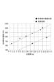
このような缶底形状を有する本発明の実施形態は、前述した従来技術と比較して、高い缶底耐圧強度を有する。ここでの缶底耐圧強度は、缶底の凹形状が完全に反転するまでのバックリング強度を指している。缶底のドーム深さhsと接地直径ds(図1参照)をhs=10.63mm,ds=45.5mmと定めて、本発明の実施形態(θ=115°,h=2.6mm)と従来技術における缶底耐圧強度を元板厚毎に比較すると、図3に示すように、本発明の実施形態は従来技術と比較して1.2~1.5倍程度強度が高くなっている。The embodiment of the present invention having such a can bottom shape has a higher can bottom pressure resistance strength than the conventional technology described above. The can bottom pressure resistance here refers to the buckling strength until the concave shape of the can bottom is completely inverted. If the dome depth hs and ground diameter ds (see Figure 1) of the can bottom are set to hs = 10.63 mm and ds = 45.5 mm, and the can bottom pressure resistance strength of the embodiment of the present invention (θ = 115°, h = 2.6 mm) and the conventional technology are compared for each original plate thickness, as shown in Figure 3, the embodiment of the present invention has a strength 1.2 to 1.5 times higher than the conventional technology.
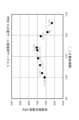
前述したリセス部22Aは、缶底1Bにおいてドーム部10と環状凸部20の成形を行った後、圧縮変形を生じさせるリフォーム成形を行うことで形成される。図4及び図5は、このリフォーム成形前のドーム深さが、13.45mm及び13.95mmの2種類の底形状の缶(容量:350ml,接地直径φ49)を用いて、前述した傾斜角度θを変えてリフォーム成形を施した場合の缶底耐圧強度の違いをそれぞれ示している。図中の括弧内の値は、傾斜角度θを変えた場合の図2に示す高さh(支持面21Aから最外部22Cまでの成形高さ)の値を示している。The
傾斜角度θが100°~125°の範囲では、所望の缶底耐圧強度を得ることができる。缶底のドーム深さhsは大きいほど缶底耐圧強度も高くなるが、ドーム深さhsを大きくすると、必然的にある範囲から内容物を充填するのに必要な缶内容積の確保が難しくなる。また、傾斜角度θは、ある範囲では大きいほど缶底耐圧強度は高くなるが、ある範囲を超えると、変形モードが変わってドーム部10のみが反転することになり、逆に缶底耐圧強度は低下することになる。
When the inclination angle θ is in the range of 100° to 125°, the desired can bottom pressure resistance can be obtained. The larger the dome depth hs of the can bottom, the higher the can bottom pressure resistance, but when the dome depth hs is increased, it inevitably becomes difficult to secure the can internal volume required to fill the contents from a certain range. Also, within a certain range, the larger the inclination angle θ, the higher the can bottom pressure resistance, but if it exceeds a certain range, the deformation mode changes and only the
前述した缶底耐圧強度は、水圧式バックリングテスターを用い、缶底については固定しない倒立状態で、缶容器の缶胴の缶軸方向の中央部付近の缶容器の内側をシールし、水を注入することで水圧により昇圧スピード30kPa/sで缶容器内部の気圧を上昇させ、缶底の凹形状が反転する最低の缶内圧として測定した。The pressure resistance strength of the can bottom mentioned above was measured using a hydraulic buckling tester. With the can bottom unfixed and in an inverted position, the inside of the can container near the center of the can body in the axial direction was sealed, and water was injected to increase the air pressure inside the can container using water pressure at a speed of 30 kPa/s. The minimum internal pressure at which the concave shape of the can bottom inverted was measured.
缶底耐圧強度は、容器の種類、内容物の液種、殺菌条件等によって要求される数値が異なるが、例えば、一部の炭酸飲料を充填する場合は、高い耐圧強度が要求されるが、その場合であっても690kPaの耐圧強度を有していれば十分であると判断される。The pressure resistance of the can bottom varies depending on the type of container, the type of liquid contained, the sterilization conditions, etc. For example, when filling some carbonated drinks, a high pressure resistance is required, but even in this case, a pressure resistance of 690 kPa is deemed sufficient.
以上、本発明の実施の形態について図面を参照して詳述してきたが、具体的な構成はこれらの実施の形態に限られるものではなく、本発明の要旨を逸脱しない範囲の設計の変更等があっても本発明に含まれる。 The above describes in detail the embodiments of the present invention with reference to the drawings, but the specific configuration is not limited to these embodiments, and the present invention includes design changes and the like that do not deviate from the gist of the present invention.
1:缶容器,1A:缶胴,1B:缶底,
10:ドーム部,10A:外周縁部,11:第1曲面,12:第2曲面,
20:環状凸部,21:支持部,21A:支持面,
22:内周面,22A:リセス部,22B:最内部,22C:最外部,
22T:テーパ面,O:缶軸,θ:傾斜角度
1: can container, 1A: can body, 1B: can bottom,
10: Dome portion, 10A: Outer periphery portion, 11: First curved surface, 12: Second curved surface,
20: annular convex portion, 21: support portion, 21A: support surface,
22: Inner peripheral surface, 22A: Recessed part, 22B: Innermost part, 22C: Outermost part,
22T: tapered surface, O: can shaft, θ: inclination angle
Claims (4)
缶胴と、缶底とを備え、
前記缶底は、
中央に缶軸Oの方向に沿って前記缶容器の内側に向けて凹むドーム部を備えると共に、
前記ドーム部の外周囲に環状の支持部を形成するように、前記缶容器の外側に向けて突出する環状凸部を備え、
前記支持部から前記ドーム部の外周縁部に至る内周面は、前記ドーム部の外周縁部が前記内周面の最内部より前記缶軸Oから離れる方向に位置するリセス部を有しており、
前記リセス部は、前記缶軸O上の縦断面視で、直線状のテーパ面を有し、
前記テーパ面と前記支持部に接する支持面との前記缶軸O側の傾斜角度が115°~125°であり、
前記支持面から前記内周面の最外部までの高さが2.6~4.0mmであり、前記内周面の最内部に接し前記缶軸Oと平行な仮想線をL1とし、前記最外部に接し前記缶軸Oと平行な仮想線をL2とした場合に、前記仮想線L1と前記仮想線L2間の距離(リセス部の深さ)が0.3mm~1.0mmであることを特徴とする缶容器。
A can container,
A can body and a can bottom are provided,
The can bottom is
A dome portion is provided at the center thereof, which is recessed toward the inside of the can container along the direction of the can axis O ,
a ring-shaped protrusion protruding outward from the can container so as to form a ring-shaped support portion around the outer periphery of the dome portion;
an inner circumferential surface extending from the support portion to an outer circumferential edge portion of the dome portion has a recess portion located in a direction away from the can axis O with respect to an innermost portion of the inner circumferential surface ,
The recess portion has a linear tapered surface in a vertical cross-sectional view on the can axis O,
an inclination angle between the tapered surface and a support surface in contact with the support portion on the can axis O side is 115° to 125°;
A can container characterized in that the height from the support surface to the outermost part of the inner circumferential surface is 2.6 to 4.0 mm, and when an imaginary line tangent to the innermost part of the inner circumferential surface and parallel to the can axis O is defined as L1, and an imaginary line tangent to the outermost part and parallel to the can axis O is defined as L2, the distance between the imaginary line L1 and the imaginary line L2 (the depth of the recess portion) is 0.3 mm to 1.0 mm .
2. The can container according to claim 1, wherein an imaginary line tangent to the innermost portion and parallel to the can axis O intersects with a curved surface of the dome portion.
3. The can container according to claim 1, wherein the outermost portion of the inner peripheral surface is a compressively deformed bent portion.
4. The can container according to claim 1, wherein the inner peripheral surface is free of roll forming marks.
Applications Claiming Priority (3)
| Application Number | Priority Date | Filing Date | Title |
|---|---|---|---|
| JP2019218962 | 2019-12-03 | ||
| JP2019218962 | 2019-12-03 | ||
| PCT/JP2020/041419 WO2021111798A1 (en) | 2019-12-03 | 2020-11-05 | Can container |
Publications (2)
| Publication Number | Publication Date |
|---|---|
| JPWO2021111798A1 JPWO2021111798A1 (en) | 2021-06-10 |
| JP7700680B2 true JP7700680B2 (en) | 2025-07-01 |
Family
ID=76222350
Family Applications (1)
| Application Number | Title | Priority Date | Filing Date |
|---|---|---|---|
| JP2021562516A Active JP7700680B2 (en) | 2019-12-03 | 2020-11-05 | Can container |
Country Status (6)
| Country | Link |
|---|---|
| US (1) | US12077340B2 (en) |
| EP (1) | EP4071066A4 (en) |
| JP (1) | JP7700680B2 (en) |
| CN (1) | CN114616185B (en) |
| TW (1) | TWI757989B (en) |
| WO (1) | WO2021111798A1 (en) |
Families Citing this family (3)
| Publication number | Priority date | Publication date | Assignee | Title |
|---|---|---|---|---|
| USD1057571S1 (en) * | 2021-07-28 | 2025-01-14 | Toyo Seikan Co., Ltd. | Container for a beverage |
| USD1051733S1 (en) * | 2021-07-28 | 2024-11-19 | Toyo Seikan Co., Ltd. | Beverage container |
| BE1030110B1 (en) * | 2021-12-27 | 2023-07-25 | Envases Universales de Mexico SAPI de CV | Beverage can |
Citations (1)
| Publication number | Priority date | Publication date | Assignee | Title |
|---|---|---|---|---|
| DE3930937A1 (en) | 1989-09-15 | 1991-03-28 | Schmalbach Lubeca | TWO-PIECE METAL DRINKING CAN |
Family Cites Families (25)
| Publication number | Priority date | Publication date | Assignee | Title |
|---|---|---|---|---|
| US3416703A (en) * | 1966-02-24 | 1968-12-17 | Continental Can Co | Reinforced container |
| US3693828A (en) * | 1970-07-22 | 1972-09-26 | Crown Cork & Seal Co | Seamless steel containers |
| JPS5325186A (en) * | 1976-08-20 | 1978-03-08 | Daiwa Can Co Ltd | Metallic can for drink containing carbon dioxide or the like |
| US4266685A (en) * | 1979-11-30 | 1981-05-12 | Reynolds Metals Company | Can body and method for making same |
| US4834256A (en) * | 1987-07-31 | 1989-05-30 | Pac International, Inc. | Can with domed bottom structure |
| JPH04123825A (en) * | 1990-09-11 | 1992-04-23 | Kobe Steel Ltd | Manufacture of di can body of high pressure withstanding strength and can body |
| JPH05338640A (en) * | 1990-09-17 | 1993-12-21 | Aluminum Co Of America <Alcoa> | Base profile of container made by drawing and manufacture thereof |
| US5261558A (en) * | 1990-12-21 | 1993-11-16 | Carnaudmetalbox Plc | Can bodies |
| US5718352A (en) * | 1994-11-22 | 1998-02-17 | Aluminum Company Of America | Threaded aluminum cans and methods of manufacture |
| US5421480A (en) * | 1993-04-08 | 1995-06-06 | Reynolds Metals Company | Thin-walled can having a displaceable bottom |
| US5394727A (en) | 1993-08-18 | 1995-03-07 | Aluminum Company Of America | Method of forming a metal container body |
| GB9510515D0 (en) | 1995-05-24 | 1995-07-19 | Metal Box Plc | Containers |
| US6132155A (en) * | 1995-10-23 | 2000-10-17 | Metal Container Corporation | Process for can bottom manufacture for improved strength and material use reduction |
| JPH09285832A (en) | 1996-04-23 | 1997-11-04 | Kishimoto Akira | Seamless can and its forming method |
| WO1999062765A1 (en) * | 1998-06-03 | 1999-12-09 | Crown Cork & Seal Technologies Corporation | Can bottom having improved strength and apparatus for making same |
| US5971259A (en) * | 1998-06-26 | 1999-10-26 | Sonoco Development, Inc. | Reduced diameter double seam for a composite container |
| US6296139B1 (en) * | 1999-11-22 | 2001-10-02 | Mitsubishi Materials Corporation | Can manufacturing apparatus, can manufacturing method, and can |
| TW448120B (en) * | 1999-11-26 | 2001-08-01 | Takeuchi Press | Metal container with thread |
| EP1500598B1 (en) * | 2002-04-30 | 2009-05-13 | Daiwa Can Company | Opening curled part of metal container and method of forming the opening curled part |
| US7832589B2 (en) * | 2003-12-17 | 2010-11-16 | Crown Packaging Technology, Inc. | Reclosable metal container |
| JP6448217B2 (en) | 2014-05-08 | 2019-01-09 | ユニバーサル製缶株式会社 | can |
| CN204776466U (en) | 2014-05-30 | 2015-11-18 | 环宇制罐株式会社 | Beverage tin |
| JP6713741B2 (en) * | 2014-08-20 | 2020-06-24 | ユニバーサル製缶株式会社 | can |
| US20230227237A1 (en) * | 2018-12-30 | 2023-07-20 | Caniel Industries A. T. G. Ltd. | Can and an urging member therefor |
| EP4151545A4 (en) * | 2020-05-12 | 2024-06-05 | Toyo Seikan Group Holdings, Ltd. | DEEP-DRAWN/IRONED CAN AND COATED SHEET FOR DEEP-DRAWN/IRONED CANS |
-
2020
- 2020-11-05 JP JP2021562516A patent/JP7700680B2/en active Active
- 2020-11-05 EP EP20895157.4A patent/EP4071066A4/en active Pending
- 2020-11-05 US US17/781,103 patent/US12077340B2/en active Active
- 2020-11-05 CN CN202080073788.2A patent/CN114616185B/en active Active
- 2020-11-05 WO PCT/JP2020/041419 patent/WO2021111798A1/en not_active Ceased
- 2020-11-26 TW TW109141620A patent/TWI757989B/en active
Patent Citations (1)
| Publication number | Priority date | Publication date | Assignee | Title |
|---|---|---|---|---|
| DE3930937A1 (en) | 1989-09-15 | 1991-03-28 | Schmalbach Lubeca | TWO-PIECE METAL DRINKING CAN |
Also Published As
| Publication number | Publication date |
|---|---|
| JPWO2021111798A1 (en) | 2021-06-10 |
| TW202133964A (en) | 2021-09-16 |
| TWI757989B (en) | 2022-03-11 |
| CN114616185B (en) | 2024-05-24 |
| US12077340B2 (en) | 2024-09-03 |
| WO2021111798A1 (en) | 2021-06-10 |
| CN114616185A (en) | 2022-06-10 |
| US20230002101A1 (en) | 2023-01-05 |
| EP4071066A1 (en) | 2022-10-12 |
| EP4071066A4 (en) | 2024-01-24 |
Similar Documents
| Publication | Publication Date | Title |
|---|---|---|
| JP7700680B2 (en) | Can container | |
| RU2307053C2 (en) | Face lid for can and method of its strength | |
| JP6713741B2 (en) | can | |
| JP7670051B2 (en) | Can container and its manufacturing method | |
| ES3055184T3 (en) | Seamless can body and method for producing seamless can body | |
| JP7363870B2 (en) | Method of manufacturing metal containers | |
| US20240300687A1 (en) | Can body | |
| JP2024045461A (en) | Can body | |
| WO2011027910A1 (en) | Bottomed cylinder-shaped can container body and beverage can product having the same filled with beverage | |
| JP6817106B2 (en) | Bottle type can | |
| JP7120810B2 (en) | Can body and its manufacturing method | |
| WO2019039184A1 (en) | Bottle-shaped can and capped bottle-shaped can | |
| US6182852B1 (en) | Container and method of manufacture | |
| JP5256155B2 (en) | Can body body with bottomed cylindrical body and beverage can product filled with beverage | |
| JP5256150B2 (en) | Can body body with bottomed cylindrical body and beverage can product filled with beverage | |
| JP7574621B2 (en) | Positive pressure can body | |
| WO2025074774A1 (en) | Can body, product can, and method for manufacturing can body | |
| JP7293715B2 (en) | Bottle can manufacturing method | |
| JP7494860B2 (en) | Bottle cans and bottle containers | |
| WO2024209289A1 (en) | Crown cap closure | |
| CN120731173A (en) | Two-piece metal can and method of manufacturing the same | |
| JPH01226550A (en) | Container body | |
| JP2008230708A (en) | Cap and bottle can having cap | |
| JP2023023472A (en) | Method for manufacturing can body and can | |
| JP2020083474A (en) | Can and manufacturing method thereof |
Legal Events
| Date | Code | Title | Description |
|---|---|---|---|
| A621 | Written request for application examination |
Free format text: JAPANESE INTERMEDIATE CODE: A621 Effective date: 20231012 |
|
| A131 | Notification of reasons for refusal |
Free format text: JAPANESE INTERMEDIATE CODE: A131 Effective date: 20241217 |
|
| A521 | Request for written amendment filed |
Free format text: JAPANESE INTERMEDIATE CODE: A523 Effective date: 20250207 |
|
| TRDD | Decision of grant or rejection written | ||
| A01 | Written decision to grant a patent or to grant a registration (utility model) |
Free format text: JAPANESE INTERMEDIATE CODE: A01 Effective date: 20250520 |
|
| A61 | First payment of annual fees (during grant procedure) |
Free format text: JAPANESE INTERMEDIATE CODE: A61 Effective date: 20250602 |
|
| R150 | Certificate of patent or registration of utility model |
Ref document number: 7700680 Country of ref document: JP Free format text: JAPANESE INTERMEDIATE CODE: R150 |