JP7702811B2 - Vibration Sensor Inspection System - Google Patents
Vibration Sensor Inspection System Download PDFInfo
- Publication number
- JP7702811B2 JP7702811B2 JP2021093790A JP2021093790A JP7702811B2 JP 7702811 B2 JP7702811 B2 JP 7702811B2 JP 2021093790 A JP2021093790 A JP 2021093790A JP 2021093790 A JP2021093790 A JP 2021093790A JP 7702811 B2 JP7702811 B2 JP 7702811B2
- Authority
- JP
- Japan
- Prior art keywords
- vibration sensor
- impact
- inspection system
- measurement target
- vibration
- Prior art date
- Legal status (The legal status is an assumption and is not a legal conclusion. Google has not performed a legal analysis and makes no representation as to the accuracy of the status listed.)
- Active
Links
Images




Landscapes
- Testing Of Devices, Machine Parts, Or Other Structures Thereof (AREA)
- Measurement Of Mechanical Vibrations Or Ultrasonic Waves (AREA)
Description
本発明は、振動センサ検査システムに関するものである。 The present invention relates to a vibration sensor inspection system.
近年、IoT、ICT技術の発展により、機械設備の健全性確認のために安価な振動センサが普及している。振動センサの測定データは、自動でクラウドサーバなどのデータ収集装置に保存される。測定対象機器に振動センサを取り付けた後、測定データは自動で保存されるので、測定対象機器の設置場所まで人が行って振動センサの取り付け状況を確認することは少ない。このため、振動センサが何らかの衝撃を受けて、測定対象機器から脱落したり、測定対象機器に対する取り付けが緩んでいた場合、振動センサが測定対象物の振動を正確に測定していない可能性がある。 In recent years, with the development of IoT and ICT technologies, inexpensive vibration sensors have become widespread for checking the soundness of mechanical equipment. The measurement data of the vibration sensor is automatically stored in a data collection device such as a cloud server. Since the measurement data is automatically stored after the vibration sensor is attached to the equipment to be measured, it is rare for a person to go to the installation site of the equipment to be measured to check the installation status of the vibration sensor. For this reason, if the vibration sensor receives some kind of impact and falls off the equipment to be measured, or if its attachment to the equipment to be measured becomes loose, there is a possibility that the vibration sensor will not accurately measure the vibration of the object to be measured.
下記特許文献1には、被測定物に取り付けられて前記被測定物の振動を測定する振動センサと、前記振動センサにより測定された振動データに基づいて前記振動センサの前記被測定物からの外れの有無を検出する振動センサの異常診断装置が開示されている。この異常診断装置は、振動データを周波数分析して得られた周波数スペクトルを少なくとも3つの周波数帯域に分割し、前記分割された各周波数帯域の振動値を算出し、基準振動値に対する前記各周波数帯域の前記振動値の変化に基づいて、前記振動センサの前記被測定物からの外れの有無を検出する。
The following
ところで、特許文献1の技術は、測定対象機器の運転中に振動センサの脱落を検出するものであり、運転時の振動との切り分けを「分割した複数の周波数帯域に対し、閾値を上回る周波数帯域の内、最も低い周波数帯域を特定した上で、それ以外の周波数帯域を基準と比較することで、センサの外れなのか外乱によるものかを判断できる」としている(特許文献1の段落[0043]、段落[0044]参照)。つまり、予め「閾値を上回る周波数帯域の内、最も低い周波数帯域を特定」する必要がある。また、「周波数帯域を複数に分割」することに関しては、少なくとも3つとしており、分割に関する詳細は書かれていない。そのため、分割数及び分割方法によって、判断の精度が異なってしまう。さらに、特許文献1の技術は、その原理上、振動が発生しない測定対象機器の停止中は振動センサの取り付け状態を検査することはできないため、例えば、停止期間が長い非常用設備等においては適用することが難しい。
The technology of
本発明は、上記問題点に鑑みてなされたものであり、測定対象機器の動作状況に依存せずに任意のタイミングで測定対象機器に取り付けられた振動センサを検査できる振動センサ検査システムの提供を目的とする。 The present invention was made in consideration of the above problems, and aims to provide a vibration sensor inspection system that can inspect a vibration sensor attached to a device to be measured at any time, regardless of the operating status of the device to be measured.
本発明の一態様に係る振動センサ検査システムは、測定対象機器と、前記測定対象機器に取り付けられた振動センサと、前記測定対象機器と独立したタイミングで動作し、前記振動センサに衝撃を与える衝撃装置と、前記衝撃装置によって前記振動センサに衝撃を与えたときに、前記振動センサから出力された測定データに基づいて、前記振動センサを検査する振動センサ検査装置と、を備える。 A vibration sensor inspection system according to one aspect of the present invention includes a measurement target device, a vibration sensor attached to the measurement target device, an impact device that operates at a timing independent of the measurement target device and applies an impact to the vibration sensor, and a vibration sensor inspection device that inspects the vibration sensor based on measurement data output from the vibration sensor when the impact is applied to the vibration sensor by the impact device.
上記振動センサ検査システムにおいては、前記振動センサ検査装置は、前記測定データを周波数解析し、前記振動センサの共振周波数の変化に基づいて、前記振動センサの取り付け状態を検査してもよい。 In the vibration sensor inspection system, the vibration sensor inspection device may perform frequency analysis on the measurement data and inspect the installation condition of the vibration sensor based on changes in the resonant frequency of the vibration sensor.
上記振動センサ検査システムにおいては、前記衝撃装置は、前記測定対象機器が停止しているタイミングで、前記振動センサに衝撃を与えてもよい。 In the vibration sensor inspection system, the impact device may impact the vibration sensor when the measurement target device is stopped.
上記振動センサ検査システムにおいては、前記測定対象機器に設けられた回転機械と、前記回転機械に接続された発電装置と、前記発電装置が発電した電力を蓄電する電源装置と、を備え、前記振動センサ、前記衝撃装置、及び前記振動センサ検査装置の少なくとも一つは、前記電源装置からの給電を受けて動作してもよい。 The vibration sensor inspection system includes a rotating machine provided in the measurement target device, a power generation device connected to the rotating machine, and a power supply device that stores the electricity generated by the power generation device, and at least one of the vibration sensor, the impact device, and the vibration sensor inspection device may operate by receiving power from the power supply device.
上記振動センサ検査システムにおいては、前記測定対象機器には、前記振動センサと取り付け位置が異なる第2の振動センサが取り付けられており、前記第2の振動センサも、前記電源装置からの給電を受けて動作してもよい。 In the vibration sensor inspection system, a second vibration sensor is attached to the measurement target device at a different mounting position from the vibration sensor, and the second vibration sensor may also operate by receiving power from the power supply device.
上記振動センサ検査システムにおいては、前記衝撃装置は、少なくとも電磁石と、鉄片と、を備えると共に、前記電磁石によって磁気吸引される前記鉄片の動きを利用して、前記振動センサに一定の衝撃を与えてもよい。 In the vibration sensor inspection system, the impact device may include at least an electromagnet and an iron piece, and may apply a certain impact to the vibration sensor by utilizing the movement of the iron piece that is magnetically attracted by the electromagnet.
上記振動センサ検査システムにおいては、前記振動センサの検査結果を表示する表示部を備えてもよい。 The vibration sensor inspection system may be provided with a display unit that displays the inspection results of the vibration sensor.
上記振動センサ検査システムにおいては、前記衝撃装置を遠隔操作する通信部を備えてもよい。 The vibration sensor inspection system may be provided with a communication unit for remotely controlling the impact device.
上記振動センサ検査システムにおいては、前記振動センサと前記衝撃装置は、共通のケースに収容されていてもよい。 In the vibration sensor inspection system, the vibration sensor and the impact device may be housed in a common case.
上記振動センサ検査システムにおいては、前記測定対象機器は、ポンプ装置及び当該ポンプ装置に接続される配管類を含んでもよい。 In the vibration sensor inspection system, the measurement target device may include a pump device and piping connected to the pump device.
上記本発明の一態様によれば、測定対象機器の動作状況に依存せずに任意のタイミングで測定対象機器に取り付けられた振動センサを検査できる振動センサ検査システムを提供できる。 According to one aspect of the present invention, it is possible to provide a vibration sensor inspection system that can inspect a vibration sensor attached to a device to be measured at any time, regardless of the operating status of the device to be measured.
以下、本発明の一実施形態に係る振動センサ検査システムについて図面を参照して説明する。以下の説明では、振動センサが取り付けられる測定対象機器として、ポンプ装置を例示する。 The following describes a vibration sensor inspection system according to one embodiment of the present invention with reference to the drawings. In the following description, a pump device is used as an example of a measurement target device to which a vibration sensor is attached.
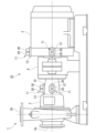
図1は、一実施形態に係る測定対象機器1の側面図である。図2は、一実施形態に係る測定対象機器1の正面図である。
図1に示すように、測定対象機器1は、ポンプ部2と、モータ部3(回転機械)と、軸カップリング部4と、を備えている。
Fig. 1 is a side view of a
As shown in FIG. 1, the
ポンプ部2は、正面に吸込口2aを備え、上面に吐出口2bを備える渦巻きポンプである。ポンプ部2の背面には、ポンプ軸を軸支する軸受を収容している軸受部2cが突出して設けられている。ポンプ軸は、軸受部2cから背面側に突出し、モータ部3の回転軸と、軸カップリング部4を介して接続されている。モータ部3のポンプ部2と反対側の端部には、発電装置5が接続されている。発電装置5は、モータ部3の回転によって発電する。
The
測定対象機器1には、複数の振動検出ユニット11が取り付けられている。図1に示す振動検出ユニット11は、軸受部2c及びモータ部3に取り付けられている。振動検出ユニット11は、軸受部2c及びモータ部3において、それぞれ、図2に示すように、12時方向と3時方向に取り付けられている。なお、上述した振動検出ユニット11の設置数、設置場所、設置角度等は、あくまで一例であり、適宜変更され得る。例えば、振動検出ユニット11は、ポンプ部2(ポンプ装置)に接続された配管類に設置されていても構わない。
A plurality of
振動検出ユニット11は、図1に示すように、取付ベース12を介して測定対象機器1に取り付けられている。取付ベース12は、ねじのよるねじ固定や、マグネットによる磁着、あるいは接着剤による接着によって、測定対象機器1に取り付けられている。取付ベース12は、振動センサ20及び衝撃装置30を支持している。衝撃装置30は、振動センサ20に固定された状態で、振動センサ20と共にケース13内に収容されている。
As shown in FIG. 1, the
図3は、一実施形態に係る振動センサ検査システム10の構成図である。
図3に示す振動センサ検査システム10は、振動センサ20と、衝撃装置30と、振動センサ検査装置40と、電源装置50と、を備えている。電源装置50は、上述した発電装置5と接続され、発電装置5が発電した電気を蓄電すると共に、当該蓄電した電気を振動センサ検査装置40、衝撃装置30、及び振動センサ20に給電する。なお、電源装置50は、一次電池や商用電源等であってもよく、一次電池や商用電源等と上述した蓄電機能とを併用しても構わない。
FIG. 3 is a configuration diagram of a vibration
The vibration
図3に示す電源装置50は、充電部51と、蓄電部52と、給電部53と、を備えている。充電部51は、例えば、発電装置5で生じた交流電流を直流電流に変換する充電回路を有する。蓄電部52は、例えば、二次電池やキャパシタなどであり、充電部51に接続されて電気を蓄電する。給電部53は、蓄電部52に蓄えた電気を振動センサ検査装置40、衝撃装置30、及び振動センサ20に給電する。また、給電部53は、他の振動検出ユニット11とも接続され、その振動センサ20(第2の振動センサ)に給電可能とされている。なお、給電形式は、ケーブル接続による接触給電であっても、コイルを介した非接触給電であってもよい。
The
図3に示す振動センサ検査装置40は、動作部41と、測定部42と、判定部43と、表示部44と、記録部45と、通信部46と、を備えている。動作部41は、衝撃装置30を動作させるものであり、例えば、後述する図4及び図5に示す給電部53のスイッチ53bをON/OFFするアクチュエータである。測定部42は、振動センサ20から測定データを取得する。
The vibration
判定部43は、衝撃装置30によって振動センサ20に衝撃を与えたときに、振動センサ20から出力された測定データに基づいて、振動センサ20の取り付け状態や異常の有無を判定する。表示部44は、判定部43の判定結果等を表示するディスプレイ装置である。なお、判定部43の判定結果は、通信部46を介して管理者が所有する端末装置(パーソナルコンピューター、スマートフォン、タブレット端末など)に表示させても構わない。
The
記録部45は、ハードディスクドライブ(HDD)、ソリッドステートドライブ(SSD)やその他のフラッシュメモリ(USBメモリ、SDカード)等を備え、振動センサ20の測定データや判定部43の判定結果等を記録する。また、記録部45には、判定部43が読み出して実行するためのプログラムが格納されており、判定部43はそのプログラムに従って、振動センサ20の取り付け状態や異常の有無を判定する。通信部46は、管理者が所有する端末装置と直接または中継器やインターネット等を介して間接的に、有線または無線通信するものである。管理者は、通信部46によって、遠隔地から任意のタイミングで衝撃装置30を遠隔操作できるようになっている。
The
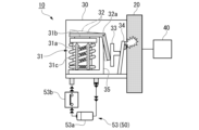
図4は、一実施形態に係る衝撃装置30の構成図である。図5は、一実施形態に係る衝撃装置30が動作したときの様子を示す図である。
図4及び図5に示すように、衝撃装置30は、電磁石31によって磁気吸引される鉄片32の動きを利用して、振動センサ20に一定の衝撃を与える。本実施形態の衝撃装置30は、継電器(リレー)の動作原理を応用したものであるが、振動センサ20に一定の衝撃を与えることができる構成であれば他のソレノイドアクチュエータの動作原理を利用しても構わない。
Fig. 4 is a configuration diagram of the
4 and 5, the
電磁石31は、円筒状のホルダ31aと、ホルダ31aの内側に収容された鉄心31bと、ホルダ31aの外側に巻き付けられたコイル31cと、を備えている。コイル31cは、電源装置50の給電部53の給電回路に接続されている。当該給電回路には、電源53aと、コイル31cに対する通電及び非通電を切り替えるスイッチ53bと、が設けられている。
The
鉄片32は、くの字状に屈曲した板形状を有している。鉄片32は、支持部材35によって、その屈曲部32aを中心に回動自在に支持されている。鉄片32は、付勢部材33から図示しないヒンジバネによって付勢を受け、図4に示す非通電状態では、電磁石31の鉄心31bから離間している。図5に示す通電状態では、鉄片32は、電磁石31の鉄心31bに磁着されることで、付勢部材33を押し返し、打撃部材34を振動センサ20に衝突させる。
The
打撃部材34は、例えば、突起が付いた板部材であり、付勢部材33と振動センサ20との間に配置されている。図5に示す通電状態では、打撃部材34は、鉄片32から付勢部材33を介して押圧されて弾性変形し、振動センサ20に衝突する。図4に示す非通電状態では、打撃部材34は、復元変形して、振動センサ20から離間する。
The striking
続いて、上記構成の振動センサ検査システム10の動作(振動センサ20の取り付け状態の検査、振動センサ20の異常の検査)について説明する。なお、以下の動作は、振動センサ検査装置40が主体となって動作する。
Next, the operation of the vibration
図6は、一実施形態に係る振動センサ検査システム10の動作を説明するフローチャートである。
図6に示すように、振動センサ検査装置40は、通信部46が外部信号を受信したり、タイマーによる信号を受信した場合、検査モードに切り替える(ステップS1)。なお、外部信号とは、例えば、管理者の端末装置から任意のタイミングで入力された信号である。タイマーによる信号とは、振動センサ20の定期検査のため、例えば1ヶ月毎に入力される信号である。
FIG. 6 is a flowchart illustrating the operation of the vibration
6, when the
次に、振動センサ検査装置40は、振動センサ20から出力された測定データに基づいて、測定対象機器1が動作しているか否かを判定する(ステップS2)。測定対象機器1が動作している場合、振動センサ検査装置40は、通常の測定モードに戻る。そして、振動センサ検査装置40は、振動センサ20によって測定対象機器1の振動を測定しながら、次に外部信号やタイマーによる信号が入力されるまで待機する(ステップS1)。
Next, the vibration
測定対象機器1が動作していない場合、振動センサ検査装置40は、コイル31cに通電し(ステップS3)、上述した図5に示すように衝撃装置30を作動させる(ステップS4)。次に、振動センサ検査装置40は、衝撃装置30によって振動センサ20に衝撃を与えたときに、振動センサ20に発生した振動を、振動センサ20にて測定する(ステップS5)。そして、振動センサ検査装置40は、振動センサ20から出力された測定データを記録部45に一時保存すると共に、当該測定データを周波数解析し、その振動値を算出する(ステップS6)。
If the
次に、振動センサ検査装置40は、衝撃装置30によって振動センサ20に衝撃を与えたときに測定した測定データと、振動センサ20の設置時に記録した参照データと、を比較して振動センサ20を検査する(ステップS7)。参照データとは、振動センサ20の設置時に、測定対象機器1が停止している状態で、衝撃装置30によって振動センサ20に衝撃を与えたときに、振動センサ20に発生した振動を、振動センサ20にて測定したものである。
The vibration
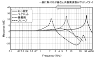
図7は、一実施形態に係る振動センサ20の取り付け状態と共振周波数との関係を示すグラフである。図7において「ねじ固定」とは、測定対象機器1に振動センサ20をねじで固定した場合を示している。また、「マグネット」とは、測定対象機器1に振動センサ20をマグネットで磁着させた場合を示している。また、「接着剤」とは、測定対象機器1に振動センサ20を接着剤で接着した場合を示している。また、「プローブ」とは、測定対象機器1に振動センサ20を人の手で押し当てた場合を示している。
Figure 7 is a graph showing the relationship between the attachment state of the
図7に示すように、振動センサ20の共振周波数(図7に示すグラフのピーク)は、取り付け状態に応じて変化している。具体的に、振動センサ20の共振周波数は、「ネジ固定」→「マグネット」→「接着剤」→「プローブ」の順に、取り付け強度が弱いほど下がっている。つまり、一般に、振動センサ20の取り付けが緩むと振動センサ20の共振周波数が下がっていくことが分かる。
As shown in FIG. 7, the resonant frequency of the vibration sensor 20 (the peak of the graph shown in FIG. 7) changes depending on the mounting condition. Specifically, the resonant frequency of the
図6に戻り、ステップS7において、振動センサ検査装置40は、測定データの共振周波数が、参照データの共振周波数よりも下がっていると判定した場合、振動センサ20の取り付けが緩んだり、脱落している可能性があるとして、振動センサ20の取り付け異常と判定する。また、振動センサ検査装置40は、測定データの振動値(振幅、周波数、位相等)が、参照データの振動値から変化している場合、振動センサ20の取り付け状態以外の何らかの異常が生じている可能性があるとして、振動センサ20の異常と判定する。一方、振動センサ検査装置40は、測定データの共振周波数や振動値が、参照データから変化していない若しくは殆ど変化していない場合は、正常と判定する。
Returning to FIG. 6, in step S7, if the vibration
次に、振動センサ検査装置40は、上述した振動センサ20の検査結果を表示部44に表示する(ステップS8)と共に、そのデータを記録部45に記録する(ステップS9)。また、振動センサ検査装置40は、上述した振動センサ20の検査結果を、通信部46を介して管理者の端末装置などに通知する(ステップS10)
以上により、振動センサ20の検査が完了する。
Next, the vibration
With the above, the inspection of the
このように、上述した本実施形態に係る振動センサ検査システム10は、測定対象機器1と、測定対象機器1に取り付けられた振動センサ20と、測定対象機器1と独立したタイミングで動作し、振動センサ20に衝撃を与える衝撃装置30と、衝撃装置30によって振動センサ20に衝撃を与えたときに、振動センサ20から出力された測定データに基づいて、振動センサ20を検査する振動センサ検査装置40と、を備える。この構成によれば、測定対象機器1の動作状況に依存せずに任意のタイミングで測定対象機器1に取り付けられた振動センサ20を検査できる。
As described above, the vibration
また、本実施形態においては、振動センサ検査装置40は、測定データを周波数解析し、振動センサ20の共振周波数の変化に基づいて、振動センサ20の取り付け状態を検査する。この構成によれば、振動センサ20の緩みなどの取り付け状態を検査することができる。
In addition, in this embodiment, the vibration
また、本実施形態においては、衝撃装置30は、測定対象機器1が停止しているタイミングで、振動センサ20に衝撃を与える。この構成によれば、測定対象機器1の動作振動が外乱にならないため、振動センサ20の検査精度を向上させることができる。
In addition, in this embodiment, the
また、本実施形態においては、測定対象機器1に設けられたモータ部3と、モータ部3に接続された発電装置5と、発電装置5が発電した電力を蓄電する電源装置50と、を備え、振動センサ20、衝撃装置30、及び振動センサ検査装置40の少なくとも一つは、電源装置50からの給電を受けて動作する。この構成によれば、測定対象機器1に接続された発電装置5によって、振動センサ検査システム10を動作させることができるため、電池の補充や商用電源などから電線を引いてくることが困難な場所でも振動センサ20の検査を行うことができる。
In addition, in this embodiment, the device to be measured 1 includes a
また、本実施形態においては、測定対象機器1には、振動センサ20と取り付け位置が異なる第2の振動センサ20が取り付けられており、第2の振動センサ20も、電源装置50からの給電を受けて動作する。この構成によれば、測定対象機器1に接続された発電装置5によって、複数の振動センサ20を動作させることができる。
In addition, in this embodiment, a
また、本実施形態においては、衝撃装置30は、少なくとも電磁石31と、鉄片32と、を備えると共に、電磁石31によって磁気吸引される鉄片32の動きを利用して、振動センサ20に一定の衝撃を与える。この構成によれば、省電力で一定の衝撃を振動センサ20に与えることができる。
In addition, in this embodiment, the
また、本実施形態においては、振動センサ20の検査結果を表示する表示部44を備える。この構成によれば、管理者等が振動センサ20の検査結果を確認することができる。
In addition, this embodiment is provided with a
また、本実施形態においては、衝撃装置30を遠隔操作する通信部46を備える。この構成によれば、管理者が測定対象機器1の設置場所に行かなくても、振動センサ20の検査を行うことができる。
In addition, in this embodiment, a
また、本実施形態においては、振動センサ20と衝撃装置30は、共通のケース13に収容されている。この構成によれば、振動センサ20に対する衝撃装置30の位置決めや、測定対象機器1に対する振動センサ20及び衝撃装置30の設置が容易になる。
In addition, in this embodiment, the
また、本実施形態においては、測定対象機器1は、ポンプ装置及び当該ポンプ装置に接続される配管類を含む。例えば、非常用設備のポンプ装置は、何時運転するか分からないため、上述した振動センサ検査システム10を適用することで、このポンプ装置乃至その配管類に取り付けられた振動センサ20を任意のタイミングで検査することができる。
In addition, in this embodiment, the
以上、本発明の好ましい実施形態を記載し説明してきたが、これらは本発明の例示的なものであり、限定するものとして考慮されるべきではないことを理解すべきである。追加、省略、置換、およびその他の変更は、本発明の範囲から逸脱することなく行うことができる。従って、本発明は、前述の説明によって限定されていると見なされるべきではなく、特許請求の範囲によって制限されている。 Although preferred embodiments of the present invention have been described and illustrated above, it should be understood that these are illustrative of the present invention and should not be considered as limiting. Additions, omissions, substitutions, and other modifications can be made without departing from the scope of the present invention. Thus, the present invention should not be considered as limited by the foregoing description, but rather by the scope of the claims.
例えば、振動センサ検査システム10は、図8や図9に示すような変形例を採用し得る。
For example, the vibration
図8は、一実施形態の変形例に係る振動センサ20及び衝撃装置30の取り付け状態を示す測定対象機器1の側面図である。
図8に示す振動センサ20及び衝撃装置30は、共通の取付ベース12に取り付けられている。つまり、図8に示すように、振動センサ20及び衝撃装置30は、共通のケース13(図1参照)に収容しなくても構わない。また、衝撃装置30を既設の振動センサ20に固定しても構わない。
FIG. 8 is a side view of the
The
図9は、一実施形態の変形例に係る振動センサ検査システム10の構成図である。
図9に示す振動センサ検査システム10は、上述した判定部43が、クラウドサーバやパソコンなどの外部装置60に設けられている。つまり、振動センサ検査装置40は、通信部46によって振動センサ20の測定データを外部装置60に提供し、外部装置60が例えばクラウドサーバ上において振動センサ20を検査してもよい。
FIG. 9 is a configuration diagram of a vibration
9, the above-mentioned
また、例えば、上記実施形態では、測定対象機器1としてポンプ装置を例示したが、例えば、上述した特許文献1に示すような発電機であってもよい。また、測定対象機器1は、その他、電動機や内燃機関などの回転機械であってもよく、当該回転機械によって動作する各種装置であってもよい。
In addition, for example, in the above embodiment, a pump device is exemplified as the
1 測定対象機器
2 ポンプ部
2a 吸込口
2b 吐出口
2c 軸受部
3 モータ部
4 軸カップリング部
5 発電装置
10 振動センサ検査システム
11 振動検出ユニット
12 取付ベース
13 ケース
20 振動センサ
30 衝撃装置
31 電磁石
31a ホルダ
31b 鉄心
31c コイル
32 鉄片
32a 屈曲部
33 付勢部材
34 打撃部材
35 支持部材
40 振動センサ検査装置
41 動作部
42 測定部
43 判定部
44 表示部
45 記録部
46 通信部
50 電源装置
51 充電部
52 蓄電部
53 給電部
53a 電源
53b スイッチ
60 外部装置
1
Claims (9)
前記測定対象機器に取り付けられた振動センサと、
前記測定対象機器と独立したタイミングで動作し、前記振動センサに衝撃を与える衝撃装置と、
前記衝撃装置によって前記振動センサに衝撃を与えたときに、前記振動センサから出力された測定データに基づいて、前記振動センサを検査する振動センサ検査装置と、を備え、
前記衝撃装置は、少なくとも電磁石と、鉄片と、を備えると共に、前記電磁石によって磁気吸引される前記鉄片の動きを利用して、前記振動センサに一定の衝撃を与える、ことを特徴とする振動センサ検査システム。 A measurement target device;
A vibration sensor attached to the measurement target device;
an impact device that operates at a timing independent of the measurement target device and applies an impact to the vibration sensor;
a vibration sensor inspection device that inspects the vibration sensor based on measurement data output from the vibration sensor when an impact is applied to the vibration sensor by the impact device ,
The vibration sensor inspection system is characterized in that the impact device comprises at least an electromagnet and an iron piece, and applies a certain impact to the vibration sensor by utilizing the movement of the iron piece magnetically attracted by the electromagnet .
前記回転機械に接続された発電装置と、
前記発電装置が発電した電力を蓄電する電源装置と、を備え、
前記振動センサ、前記衝撃装置、及び前記振動センサ検査装置の少なくとも一つは、前記電源装置からの給電を受けて動作する、ことを特徴とする請求項1~3のいずれか一項に記載の振動センサ検査システム。 A rotating machine provided in the measurement target device;
a power generation device connected to the rotary machine;
a power supply device that stores the power generated by the power generation device,
4. The vibration sensor inspection system according to claim 1, wherein at least one of the vibration sensor, the impact device, and the vibration sensor inspection device operates by receiving power from the power supply device.
前記第2の振動センサも、前記電源装置からの給電を受けて動作する、ことを特徴とする請求項4に記載の振動センサ検査システム。 a second vibration sensor is attached to the measurement target device at a different attachment position from the vibration sensor;
5. The vibration sensor inspection system according to claim 4, wherein the second vibration sensor also operates by receiving power from the power supply device.
Priority Applications (1)
| Application Number | Priority Date | Filing Date | Title |
|---|---|---|---|
| JP2021093790A JP7702811B2 (en) | 2021-06-03 | 2021-06-03 | Vibration Sensor Inspection System |
Applications Claiming Priority (1)
| Application Number | Priority Date | Filing Date | Title |
|---|---|---|---|
| JP2021093790A JP7702811B2 (en) | 2021-06-03 | 2021-06-03 | Vibration Sensor Inspection System |
Publications (2)
| Publication Number | Publication Date |
|---|---|
| JP2022185887A JP2022185887A (en) | 2022-12-15 |
| JP7702811B2 true JP7702811B2 (en) | 2025-07-04 |
Family
ID=84441985
Family Applications (1)
| Application Number | Title | Priority Date | Filing Date |
|---|---|---|---|
| JP2021093790A Active JP7702811B2 (en) | 2021-06-03 | 2021-06-03 | Vibration Sensor Inspection System |
Country Status (1)
| Country | Link |
|---|---|
| JP (1) | JP7702811B2 (en) |
Families Citing this family (1)
| Publication number | Priority date | Publication date | Assignee | Title |
|---|---|---|---|---|
| CN113390504B (en) * | 2021-07-19 | 2024-03-26 | 水利部交通运输部国家能源局南京水利科学研究院 | Low-frequency vibration sensor verification system and verification method |
Citations (4)
| Publication number | Priority date | Publication date | Assignee | Title |
|---|---|---|---|---|
| JP2009236596A (en) | 2008-03-26 | 2009-10-15 | Jfe Steel Corp | Vibration sensor and method for determining state of the same |
| JP2014505262A (en) | 2011-02-10 | 2014-02-27 | シーメンス エナジー インコーポレイテッド | Vibration sensor status monitoring method |
| JP2017134047A (en) | 2016-01-27 | 2017-08-03 | 富士電機株式会社 | Acceleration sensor device, monitoring system, and diagnostic method |
| JP2021032018A (en) | 2019-08-28 | 2021-03-01 | 株式会社東海理化電機製作所 | Abnormality detection device and electronic key |
Family Cites Families (1)
| Publication number | Priority date | Publication date | Assignee | Title |
|---|---|---|---|---|
| JPH06148234A (en) * | 1992-11-06 | 1994-05-27 | Omron Corp | Acceleration detection device and self-diagnosis method thereof |
-
2021
- 2021-06-03 JP JP2021093790A patent/JP7702811B2/en active Active
Patent Citations (4)
| Publication number | Priority date | Publication date | Assignee | Title |
|---|---|---|---|---|
| JP2009236596A (en) | 2008-03-26 | 2009-10-15 | Jfe Steel Corp | Vibration sensor and method for determining state of the same |
| JP2014505262A (en) | 2011-02-10 | 2014-02-27 | シーメンス エナジー インコーポレイテッド | Vibration sensor status monitoring method |
| JP2017134047A (en) | 2016-01-27 | 2017-08-03 | 富士電機株式会社 | Acceleration sensor device, monitoring system, and diagnostic method |
| JP2021032018A (en) | 2019-08-28 | 2021-03-01 | 株式会社東海理化電機製作所 | Abnormality detection device and electronic key |
Also Published As
| Publication number | Publication date |
|---|---|
| JP2022185887A (en) | 2022-12-15 |
Similar Documents
| Publication | Publication Date | Title |
|---|---|---|
| US12510403B2 (en) | Systems and methods for monitoring of mechanical and electrical machines | |
| CN109563840B (en) | Pump assembly and method | |
| US7949479B2 (en) | In on or relating to rotating machines | |
| US7852105B2 (en) | Winding diagnostic system and method | |
| CN102420499A (en) | Real time measurement of rotor surface | |
| JP7702811B2 (en) | Vibration Sensor Inspection System | |
| CN103166079B (en) | motor for motor vehicle | |
| JP2010151773A (en) | Compound sensor for monitoring state of rotation device | |
| US11959825B2 (en) | Method and a condition monitoring device for monitoring a rotating equipment | |
| US10145884B2 (en) | Smart cord reel | |
| JP7168738B2 (en) | Smart watch watch automatic winding mechanism with watch watch identification | |
| CN103090901A (en) | On-line calibration method for sensor | |
| US12255568B2 (en) | Monitoring circuit for electrical motor space heaters | |
| JP2008109806A (en) | Rotating electric machine to which IC tag with sensor is applied, abnormality detecting device for the rotating electric machine, and abnormality detecting method for the rotating electric machine | |
| TWI881368B (en) | Sensing device for automatic detection of parameters and method of operation thereof | |
| EP4431754A1 (en) | System and method for determining condition of sleeve bearing | |
| JP7707954B2 (en) | Gear Fault Detection System | |
| HK40068114B (en) | Smart automatic watch winding-mechanism with watch identification | |
| CN111480285B (en) | Electronic seal device, motor assembly and electronic seal verification method | |
| JP2017190233A (en) | Operation input device |
Legal Events
| Date | Code | Title | Description |
|---|---|---|---|
| A621 | Written request for application examination |
Free format text: JAPANESE INTERMEDIATE CODE: A621 Effective date: 20240530 |
|
| A977 | Report on retrieval |
Free format text: JAPANESE INTERMEDIATE CODE: A971007 Effective date: 20250131 |
|
| A131 | Notification of reasons for refusal |
Free format text: JAPANESE INTERMEDIATE CODE: A131 Effective date: 20250204 |
|
| A521 | Request for written amendment filed |
Free format text: JAPANESE INTERMEDIATE CODE: A523 Effective date: 20250407 |
|
| TRDD | Decision of grant or rejection written | ||
| A01 | Written decision to grant a patent or to grant a registration (utility model) |
Free format text: JAPANESE INTERMEDIATE CODE: A01 Effective date: 20250527 |
|
| A61 | First payment of annual fees (during grant procedure) |
Free format text: JAPANESE INTERMEDIATE CODE: A61 Effective date: 20250624 |
|
| R150 | Certificate of patent or registration of utility model |
Ref document number: 7702811 Country of ref document: JP Free format text: JAPANESE INTERMEDIATE CODE: R150 |