JP7704443B2 - ROBOTIC MICROSURGICAL ASSEMBLY, OPERATING ARENA, AND METHODS - Google Patents
ROBOTIC MICROSURGICAL ASSEMBLY, OPERATING ARENA, AND METHODS Download PDFInfo
- Publication number
- JP7704443B2 JP7704443B2 JP2022548512A JP2022548512A JP7704443B2 JP 7704443 B2 JP7704443 B2 JP 7704443B2 JP 2022548512 A JP2022548512 A JP 2022548512A JP 2022548512 A JP2022548512 A JP 2022548512A JP 7704443 B2 JP7704443 B2 JP 7704443B2
- Authority
- JP
- Japan
- Prior art keywords
- pair
- electric
- manipulators
- assembly
- link
- Prior art date
- Legal status (The legal status is an assumption and is not a legal conclusion. Google has not performed a legal analysis and makes no representation as to the accuracy of the status listed.)
- Active
Links
Images






Classifications
-
- A—HUMAN NECESSITIES
- A61—MEDICAL OR VETERINARY SCIENCE; HYGIENE
- A61B—DIAGNOSIS; SURGERY; IDENTIFICATION
- A61B34/00—Computer-aided surgery; Manipulators or robots specially adapted for use in surgery
- A61B34/20—Surgical navigation systems; Devices for tracking or guiding surgical instruments, e.g. for frameless stereotaxis
-
- A—HUMAN NECESSITIES
- A61—MEDICAL OR VETERINARY SCIENCE; HYGIENE
- A61B—DIAGNOSIS; SURGERY; IDENTIFICATION
- A61B34/00—Computer-aided surgery; Manipulators or robots specially adapted for use in surgery
- A61B34/30—Surgical robots
-
- A—HUMAN NECESSITIES
- A61—MEDICAL OR VETERINARY SCIENCE; HYGIENE
- A61B—DIAGNOSIS; SURGERY; IDENTIFICATION
- A61B34/00—Computer-aided surgery; Manipulators or robots specially adapted for use in surgery
- A61B34/30—Surgical robots
- A61B34/37—Leader-follower robots
-
- A—HUMAN NECESSITIES
- A61—MEDICAL OR VETERINARY SCIENCE; HYGIENE
- A61B—DIAGNOSIS; SURGERY; IDENTIFICATION
- A61B34/00—Computer-aided surgery; Manipulators or robots specially adapted for use in surgery
- A61B34/70—Manipulators specially adapted for use in surgery
- A61B34/74—Manipulators with manual electric input means
-
- A—HUMAN NECESSITIES
- A61—MEDICAL OR VETERINARY SCIENCE; HYGIENE
- A61B—DIAGNOSIS; SURGERY; IDENTIFICATION
- A61B46/00—Surgical drapes
- A61B46/10—Surgical drapes specially adapted for instruments, e.g. microscopes
-
- A—HUMAN NECESSITIES
- A61—MEDICAL OR VETERINARY SCIENCE; HYGIENE
- A61B—DIAGNOSIS; SURGERY; IDENTIFICATION
- A61B50/00—Containers, covers, furniture or holders specially adapted for surgical or diagnostic appliances or instruments, e.g. sterile covers
- A61B50/10—Furniture specially adapted for surgical or diagnostic appliances or instruments
- A61B50/13—Trolleys, e.g. carts
-
- A—HUMAN NECESSITIES
- A61—MEDICAL OR VETERINARY SCIENCE; HYGIENE
- A61B—DIAGNOSIS; SURGERY; IDENTIFICATION
- A61B90/00—Instruments, implements or accessories specially adapted for surgery or diagnosis and not covered by any of the groups A61B1/00 - A61B50/00, e.g. for luxation treatment or for protecting wound edges
- A61B90/20—Surgical microscopes characterised by non-optical aspects
-
- A—HUMAN NECESSITIES
- A61—MEDICAL OR VETERINARY SCIENCE; HYGIENE
- A61B—DIAGNOSIS; SURGERY; IDENTIFICATION
- A61B90/00—Instruments, implements or accessories specially adapted for surgery or diagnosis and not covered by any of the groups A61B1/00 - A61B50/00, e.g. for luxation treatment or for protecting wound edges
- A61B90/36—Image-producing devices or illumination devices not otherwise provided for
-
- A—HUMAN NECESSITIES
- A61—MEDICAL OR VETERINARY SCIENCE; HYGIENE
- A61B—DIAGNOSIS; SURGERY; IDENTIFICATION
- A61B90/00—Instruments, implements or accessories specially adapted for surgery or diagnosis and not covered by any of the groups A61B1/00 - A61B50/00, e.g. for luxation treatment or for protecting wound edges
- A61B90/50—Supports for surgical instruments, e.g. articulated arms
-
- G—PHYSICS
- G02—OPTICS
- G02B—OPTICAL ELEMENTS, SYSTEMS OR APPARATUS
- G02B21/00—Microscopes
- G02B21/0004—Microscopes specially adapted for specific applications
- G02B21/0012—Surgical microscopes
-
- A—HUMAN NECESSITIES
- A61—MEDICAL OR VETERINARY SCIENCE; HYGIENE
- A61B—DIAGNOSIS; SURGERY; IDENTIFICATION
- A61B17/00—Surgical instruments, devices or methods
- A61B17/00234—Surgical instruments, devices or methods for minimally invasive surgery
- A61B2017/00345—Micromachines, nanomachines, microsystems
-
- A—HUMAN NECESSITIES
- A61—MEDICAL OR VETERINARY SCIENCE; HYGIENE
- A61B—DIAGNOSIS; SURGERY; IDENTIFICATION
- A61B17/00—Surgical instruments, devices or methods
- A61B2017/00367—Details of actuation of instruments, e.g. relations between pushing buttons, or the like, and activation of the tool, working tip, or the like
- A61B2017/00398—Details of actuation of instruments, e.g. relations between pushing buttons, or the like, and activation of the tool, working tip, or the like using powered actuators, e.g. stepper motors, solenoids
-
- A—HUMAN NECESSITIES
- A61—MEDICAL OR VETERINARY SCIENCE; HYGIENE
- A61B—DIAGNOSIS; SURGERY; IDENTIFICATION
- A61B17/00—Surgical instruments, devices or methods
- A61B2017/00477—Coupling
-
- A—HUMAN NECESSITIES
- A61—MEDICAL OR VETERINARY SCIENCE; HYGIENE
- A61B—DIAGNOSIS; SURGERY; IDENTIFICATION
- A61B34/00—Computer-aided surgery; Manipulators or robots specially adapted for use in surgery
- A61B34/20—Surgical navigation systems; Devices for tracking or guiding surgical instruments, e.g. for frameless stereotaxis
- A61B2034/2046—Tracking techniques
- A61B2034/2051—Electromagnetic tracking systems
-
- A—HUMAN NECESSITIES
- A61—MEDICAL OR VETERINARY SCIENCE; HYGIENE
- A61B—DIAGNOSIS; SURGERY; IDENTIFICATION
- A61B34/00—Computer-aided surgery; Manipulators or robots specially adapted for use in surgery
- A61B34/20—Surgical navigation systems; Devices for tracking or guiding surgical instruments, e.g. for frameless stereotaxis
- A61B2034/2046—Tracking techniques
- A61B2034/2055—Optical tracking systems
-
- A—HUMAN NECESSITIES
- A61—MEDICAL OR VETERINARY SCIENCE; HYGIENE
- A61B—DIAGNOSIS; SURGERY; IDENTIFICATION
- A61B34/00—Computer-aided surgery; Manipulators or robots specially adapted for use in surgery
- A61B34/30—Surgical robots
- A61B2034/305—Details of wrist mechanisms at distal ends of robotic arms
Landscapes
- Health & Medical Sciences (AREA)
- Surgery (AREA)
- Life Sciences & Earth Sciences (AREA)
- Engineering & Computer Science (AREA)
- General Health & Medical Sciences (AREA)
- Public Health (AREA)
- Veterinary Medicine (AREA)
- Biomedical Technology (AREA)
- Heart & Thoracic Surgery (AREA)
- Medical Informatics (AREA)
- Molecular Biology (AREA)
- Animal Behavior & Ethology (AREA)
- Nuclear Medicine, Radiotherapy & Molecular Imaging (AREA)
- Robotics (AREA)
- Oral & Maxillofacial Surgery (AREA)
- Pathology (AREA)
- Physics & Mathematics (AREA)
- Chemical & Material Sciences (AREA)
- Analytical Chemistry (AREA)
- General Physics & Mathematics (AREA)
- Optics & Photonics (AREA)
- Manipulator (AREA)
- Tents Or Canopies (AREA)
- External Artificial Organs (AREA)
- Prostheses (AREA)
- Conveying And Assembling Of Building Elements In Situ (AREA)
Description
本発明の目的は、手術のためのロボットアセンブリである。特に、本発明は、ロボット支援マイクロサージェリに好適なロボットアセンブリに関する。本発明はまた、ロボットサージェリアセンブリのための伝達部材に関する。本発明はまた、手術用アリーナに関する。本発明は、また、ロボット手術システムの位置決め方法に関する。 The object of the present invention is a robotic assembly for surgery. In particular, the present invention relates to a robotic assembly suitable for robot-assisted microsurgery. The present invention also relates to a transmission member for a robotic surgery assembly. The present invention also relates to a surgical arena. The present invention also relates to a method for positioning a robotic surgical system.
ロボット手術装置は、当該技術分野において一般に知られており、典型的には、スレーブロボット中央タワー(又はロボット台車)と、中央タワーから延びる複数のロボットアームを有する。各ロボットアームは、それに遠位に取り付けられた手術用エンドエフェクタを移動させるための遠隔操作ロボット電動位置決めシステム(又はマニピュレータ)からなり、手術用エンドエフェクタは、患者に対して外科的処置を行うように設計されている。マスタコントローラは、スレーブ電動位置決めシステムおよび外科用エンドエフェクタを制御するために提供される。 Robotic surgical devices are commonly known in the art and typically include a slave robotic central tower (or robotic carriage) and multiple robotic arms extending from the central tower. Each robotic arm consists of a teleoperated robotic motorized positioning system (or manipulator) for moving a surgical end effector distally attached thereto, the surgical end effector being designed to perform a surgical procedure on a patient. A master controller is provided for controlling the slave motorized positioning system and the surgical end effector.
典型的には、ロボットの中央タワーは、手術ベッドに対する複数のロボットアームの高さを調整するように、垂直方向に伸縮自在である。中央タワーはまた、ロボットアームを台車から遠ざけるために、水平方向に伸縮可能であってもよい。各ロボットアームは、各アームが中央タワーに近い折り畳まれた構成から、最も遠位の連結棒が中央タワーから最大距離にある伸長した構成まで拡張可能であるように、多数の連結棒を連結する複数のモータ駆動回転ジョイントを有する。最遠位連結棒は、通常、1つの外科用内視鏡器具に、または介在する無菌ドレーピング層を介して1つの腹腔鏡カメラに接続するための無菌アダプタを担持する。連結棒の数及び大きさの選択により、各ロボットアームは、水平面に対して特定の個別姿勢をとることができる。また、すべてのロボットアームを同時に持ち上げるために、各ロボットアームの近位根部をロボットタワーの同じ伸縮部分にヒンジで固定することも知られている。このタイプのロボット装置は、例えば、US-2019-223969およびUS-2011-27777の文献に示されている。 Typically, the central tower of the robot is vertically telescopic to adjust the height of the robotic arms relative to the surgical bed. The central tower may also be horizontally telescopic to move the robotic arms away from the trolley. Each robotic arm has multiple motor-driven rotary joints connecting multiple connecting rods such that each arm is extendable from a folded configuration close to the central tower to an extended configuration in which the most distal connecting rod is at a maximum distance from the central tower. The most distal connecting rod usually carries a sterile adapter for connection to one surgical endoscopic instrument or to one laparoscopic camera through an intervening sterile draping layer. The selection of the number and size of the connecting rods allows each robotic arm to assume a specific individual posture relative to the horizontal plane. It is also known to hinge the proximal root of each robotic arm to the same telescopic part of the robotic tower in order to lift all the robotic arms simultaneously. Robotic devices of this type are shown, for example, in US-2019-223969 and US-2011-27777.
遠隔操作ロボットのさらなる例は、US-2006-0087746、US-6731988、WO-2016-201207、CN-106175851、EP-1815949およびUS-2018-0116741に示される。 Further examples of teleoperated robots are shown in US-2006-0087746, US-6731988, WO-2016-201207, CN-106175851, EP-1815949 and US-2018-0116741.
例えばWO-2017-083253、US-5876325、WO-97-29690及びUS-2014-0069437に示されているように、手術ベッドに直接固定された1つ又は複数のロボット手術アームも知られている。 One or more robotic surgical arms fixed directly to the surgical bed are also known, as shown for example in WO-2017-083253, US-5876325, WO-97-29690 and US-2014-0069437.
患者は、典型的には、例えば病院の手術室内の無菌手術場内に位置する手術用ベッド上に横たわる。通常、手術室アリーナの無菌環境を汚染から保護するために、使い捨ての手術用ドレープがロボットの一部を包んでいる。使い捨てドレープによるロボットシステムの無菌は、ロボット器具の非無菌部分による細菌汚染を回避する。 The patient typically lies on a surgical bed located within a sterile operating arena, for example in a hospital operating room. Disposable surgical drapes usually encase parts of the robot to protect the sterile environment of the operating room arena from contamination. Sterility of the robotic system through disposable drapes avoids bacterial contamination with non-sterile parts of the robotic instruments.
マイクロサージェリ処置は、例えば、小径血管および神経からなる血管吻合の実行、ならびに外傷性病変の発生後の解剖学的部分の再建、組織の再脈管形成、四肢の再接着、移植および再植術処置などの生体組織の再建のいくつかの段階において実施される。マイクロサージェリの分野では、ロボット装置は従来のマイクロサージェリに比べて手術器具を高度に小型化することができ、同時にロボット手術システムのスレーブ手術器具への震動の伝達を低減することができるようになる。マイクロサージェリは開腹手術の手法である。従来の(非ロボットの)マイクロサージェリは、外科医が、患者の解剖学的構造を拡大することができる手術顕微鏡、典型的には光学顕微鏡とともに操作することを必要とし、したがって、マイクロサージェリのためのロボット手術装置は、好適には手術顕微鏡を備えている。患者の解剖学的範囲に関する顕微鏡の視野は、典型的には、倍率と、20~70mmの間のサイズである。DE-102005031557に示されている手術用途の既知の光学ビジョンシステムの一例である。 Microsurgery procedures are performed in several stages, for example, in the execution of vascular anastomoses consisting of small diameter vessels and nerves, as well as in the reconstruction of living tissues, such as the reconstruction of anatomical parts after the occurrence of traumatic lesions, revascularization of tissues, reattachment of limbs, transplantation and replantation procedures. In the field of microsurgery, robotic devices allow a high degree of miniaturization of surgical instruments compared to conventional microsurgery, while at the same time reducing the transmission of vibrations to the slave surgical instruments of the robotic surgical system. Microsurgery is an open surgical technique. Conventional (non-robotic) microsurgery requires the surgeon to operate with an operating microscope, typically an optical microscope, which can magnify the patient's anatomical structures, therefore robotic surgical devices for microsurgery are preferably equipped with an operating microscope. The field of view of the microscope with respect to the patient's anatomical regions is typically between 20 and 70 mm in size with a magnification. An example of a known optical vision system for surgical applications is shown in DE-102005031557.
公知のロボット手術装置は、ロボット支援腹腔鏡手術にも適しており、手術器具及び少なくとも1つのカメラは、一組の経皮トロカールを用いて患者の体内に個別に挿入され、視覚化スクリーンは、カメラから取得した患者の体内に関する腹腔鏡画像を視覚化する。ロボット支援腹腔鏡手術の一例は、US-2014-0179997に示されている。 Known robotic surgical devices are also suitable for robotically assisted laparoscopic surgery, where the surgical instruments and at least one camera are inserted separately into the patient's body using a set of percutaneous trocars, and a visualization screen visualizes laparoscopic images of the inside of the patient's body obtained from the cameras. An example of robotically assisted laparoscopic surgery is shown in US-2014-0179997.
ロボット支援マイクロサージェリ中に患者の解剖学的構造がある手術ベッドを囲む手術場は、ロボット、顕微鏡、およびロボット支援手術全体のスレーブ部分の存在に起因して、しばしば混雑を生じる。 The operating field surrounding the surgical bed where the patient's anatomy resides during robotic-assisted microsurgery often becomes congested due to the presence of the robot, microscope, and the slave parts of the entire robotic-assisted surgery.
さらに、ロボット支援マイクロサージェリのいくつかのアプリケーションは、ロボット支援手術中に無菌手術室アリーナ内で外科医の存在を望む。それによって、単一の介入中に、同じマイクロ外科医は、ロボット支援マイクロ手術から従来の(非ロボット)マイクロ手術に切り替えることを目指し、したがって、ピンセットのような従来のマイクロ手術ツールを手でつかんで、その後、ロボットシステムのマスタコントローラを手でつかんで外科医ロボット マスタ コンソールに戻る。 Furthermore, some applications of robotic-assisted microsurgery desire the presence of a surgeon within the sterile operating room arena during the robotic-assisted surgery, whereby, during a single intervention, the same microsurgeon aims to switch from robotic-assisted microsurgery to conventional (non-robotic) microsurgery, thus holding conventional microsurgery tools like tweezers in his hands, and then returning to the surgeon's robot master console with his hands holding the master controller of the robotic system.
既知のソリューションに関して改善された汎用性のロボット手術システムを提供する必要性を感じ、同時にいくつかの手術構成、それらのいくつかはまた一時的にロボットの使用を除外することができる、この理由のためにロボット システムの複雑さを増加または手術中の外科医の快適さを減らすことがなく適合することができる。 We felt the need to provide a robotic surgery system of improved versatility with respect to known solutions, which can simultaneously accommodate several surgical configurations, some of which may also temporarily exclude the use of the robot, for this reason without increasing the complexity of the robotic system or reducing the comfort of the surgeon during the operation.
外科医がロボット支援マイクロサージェリから非ロボットマイクロサージェリに切り替えることを可能にするロボット手術システムを提供する必要性が感じられ、したがって、マイクロサージェリの視野内のロボットマイクロサージェリシステムの大きさを減らすことができ、この理由のために、スレーブロボット装置の容積の大きさを増やすことなく、またはマイクロサージェリ中のマイクロサージェリの快適性を減らすことなく、ロボットマイクロサージェリのシステムの大きさを減らす。 The need is felt to provide a robotic surgery system that allows the surgeon to switch from robotic assisted microsurgery to non-robotic microsurgery, and thus reduce the size of the robotic microsurgery system within the field of view of the microsurgery, and for this reason reduce the size of the robotic microsurgery system without increasing the volumetric size of the slave robotic device or reducing the comfort of the microsurgeon during the microsurgery.
開かれた手術場において、顕微鏡の拡大された視界の下で、少なくとも2、3のロボット器具を同じかつ単一の動きで配置することを可能にするロボット手術システムを提供する必要性が感じられる。 There is a need felt to provide a robotic surgical system that allows for the placement of at least two or three robotic instruments in the same and single motion under the magnified view of a microscope in an open surgical field.
同じ、または部分的に重なった、マイクロサージェリワークスペース内で器具を正確に動かすことを可能にするロボット手術システムを提供する必要性を感じている。 We feel there is a need to provide a robotic surgical system that allows precise movement of instruments within the same or overlapping microsurgery workspace.
同じ出願人のWO-2017-064301及びUS-10864051は、特に、単一のロボットアームがロボット台車から延び、その遠位端に、平行に配置され、単一のロボットアームの同じ遠位リンクに接続された一対のスレーブ遠隔操作ロボットモータ式位置決定システムを含んでいるロボットサージェリアセンブリの解決策を開示している。ロボットアームの前記単一の遠位リンクは、2つの関節を有し、各関節は、前記2つの電動位置決めシステムの1つを取り付けられる。各電動式位置決めシステムは、直交する3方向の組に沿ってその遠位に取り付けられたシャフトを有する外科用器具を位置決めするための3つの直交する電動式スライダを有する。2つの電動位置決めシステムは、手術器具の2つの先端が共に1つの作動容積に含まれるように、互いに収束して延びる。収束する一対の電動位置決めシステムの電動スライダの作動を制御する制御システムは、スライド要素にかかる重力の成分も考慮に入れるものとする。 WO-2017-064301 and US-10864051 of the same applicant disclose inter alia a solution for a robotic surgery assembly in which a single robotic arm extends from a robot carriage and includes at its distal end a pair of slave teleoperated robotic motorized positioning systems arranged in parallel and connected to the same distal link of the single robotic arm. The single distal link of the robotic arm has two joints, each joint being fitted with one of the two motorized positioning systems. Each motorized positioning system has three orthogonal motorized sliders for positioning a surgical instrument having a shaft attached to its distal end along a set of three orthogonal directions. The two motorized positioning systems extend convergingly with each other such that the two tips of the surgical instrument are both included in one working volume. The control system controlling the actuation of the motorized sliders of the pair of converging motorized positioning systems shall also take into account the component of gravity acting on the sliding elements.
いくつかの観点で有利であるにもかかわらず、収束する手術器具シャフトのこのような解決策は、同じ作業ボリューム内の両方の外科チップの位置決めの制御に関連する不都合を生じやすく、前記電動スライダを有する電動マニピュレータは、互いに対してオフセットして配向される。 Despite being advantageous in some respects, such a solution of converging surgical instrument shafts is prone to inconveniences related to controlling the positioning of both surgical tips within the same working volume, the motorized manipulators with said motorized sliders being oriented offset relative to each other.
ロボット手術システムに対する制御を単純化する必要性が感じられるが、この理由のために、それにそれぞれ遠位に取り付けられた2つの手術器具が同じ手術ボリュームに到達するための能力を失うことなく、ロボット手術システムに対する制御を単純化することができる。 There is a perceived need to simplify the control over a robotic surgical system, and for this reason, the control over the robotic surgical system can be simplified without losing the ability for two surgical instruments, each distally attached thereto, to reach the same surgical volume.
公知技術を参照して述べた欠点を克服し、マイクロサージェリに特に適したロボット手術システムを提供することが本発明の範疇である。 The scope of the present invention is to overcome the shortcomings described with reference to the known art and to provide a robotic surgical system that is particularly suitable for microsurgery.
これらおよび他の範囲は、請求項1による、および請求項33によるロボットサージェリアセンブリ、ならびに請求項12による、および請求項32による手術場アリーナによって達成される。 These and other scopes are achieved by the robotic surgery assembly according to claim 1 and according to claim 33, and the operating theatre arena according to claim 12 and according to claim 32.
いくつかの好ましい実施形態は、従属請求項の主題である。 Some preferred embodiments are the subject of dependent claims.
本発明の一態様によれば、ロボット支援マイクロサージェリのためのロボットサージェリアセンブリは、マクロ位置決めアームと、前記マクロ位置決めアームの同じ第1リンクに両方取り付けられた一対の電動マニピュレータと、を備える。前記マクロポジショニングアームは、パッシブマクロポジショニングアームであってもよい。同一の第1リンクは、マクロポジショニングアームの最遠位リンクであってもよい。同第1リンクは、前記一対の電動マニピュレータの相互の位置及び向きを剛性的に決定することができる剛性リンクであってもよい。受動的マクロポジショニングアームは、磁気ブレーキだけでなく、前記ブレーキの少なくともいくつかをロック/アンロックするための電気磁気手段、例えば1つ以上のソレノイドバルブ、を含んでいてもよい。 According to one aspect of the invention, a robotic surgery assembly for robot-assisted microsurgery comprises a macropositioning arm and a pair of motorized manipulators both attached to the same first link of the macropositioning arm. The macropositioning arm may be a passive macropositioning arm. The same first link may be the most distal link of the macropositioning arm. The same first link may be a rigid link capable of rigidly determining the position and orientation of the pair of motorized manipulators relative to one another. The passive macropositioning arm may include magnetic brakes as well as electro-magnetic means, e.g. one or more solenoid valves, for locking/unlocking at least some of the brakes.
本発明の一態様によれば、各電動マニピュレータは、少なくとも3つの相互に直交する電動リニアスライダを有する。各スライダは、溝および/またはレールなどのそれぞれの案内要素に関連付けられることができる。各マニピュレータは、直交マニピュレータであってもよい。つのマニピュレータは、互いに側面となるように配置されてもよく、マクロ位置決め装置の同じ第1リンクから実質的に同じ距離であってもよい。 According to one aspect of the invention, each motorized manipulator has at least three mutually orthogonal motorized linear sliders. Each slider can be associated with a respective guiding element, such as a groove and/or a rail. Each manipulator may be an orthogonal manipulator. The two manipulators may be positioned flanking each other and at substantially the same distance from the same first link of the macropositioning device.
本発明の一態様によれば、各電動マニピュレータは、手術器具に接続するのに適した結合装置を含む無菌アダプタに接続される。外科用器具は、好ましくは、無菌アダプタから着脱可能である。無菌アダプタは、好ましくは、それぞれのマニピュレータから着脱可能である。前記伝達部材と前記無菌アダプタのそれぞれとの間に介在して少なくとも1つのモータボックスアセンブリが設けられ、該モータボックスアセンブリは、前記シャフトを有するそれぞれの外科用器具を該シャフトの長手方向の展開軸を中心に回動させるのに適した回転モータ(461)を有することができる。前記回転軸は、前記シャフトに対して偏心していてもよい。 According to one aspect of the invention, each motorized manipulator is connected to a sterile adaptor including a coupling device suitable for connecting to a surgical instrument. The surgical instrument is preferably detachable from the sterile adaptor. The sterile adaptor is preferably detachable from the respective manipulator. At least one motor box assembly is provided between the transmission member and each of the sterile adaptors, and the motor box assembly may include a rotary motor (461) suitable for rotating each of the surgical instruments having the shaft about a longitudinal axis of deployment of the shaft. The axis of rotation may be eccentric with respect to the shaft.
本発明の一態様によれば、それぞれの電動マニピュレータとそれぞれの無菌アダプタとの間には、電動マニピュレータの少なくとも1つの電動リニアスライダとそれぞれの無菌アダプタの前記結合装置との相対相互位置及び向きを剛性的に決定するためのそれぞれの伝達部材が介在される。 According to one aspect of the present invention, a transmission member is interposed between each electric manipulator and each sterile adapter for rigidly determining the relative mutual position and orientation between at least one electric linear slider of the electric manipulator and the coupling device of each sterile adapter.
前記伝達部材は、各無菌アダプタのシャフトが、それぞれの電動マニピュレータの前記電動リニアスライダの各々及び全てのスライド方向に関してオフセットされるように、線形及び角度の両方のオフセットを規定してもよい。 The transmission member may define both a linear and an angular offset such that the shaft of each sterile adapter is offset with respect to each and every sliding direction of the motorized linear slider of the respective motorized manipulator.
外科用器具は、各無菌アダプタに着脱可能に接続されてもよい。 A surgical instrument may be removably connected to each sterile adapter.
外科用器具のシャフトは、収束して延びてもよい。 The shafts of the surgical instruments may extend in a converging manner.
前記一対の電動マニピュレータの第1の電動マニピュレータの電動リニアスライダは、前記一対の電動マニピュレータの第2の電動マニピュレータの電動リニアスライダに対して平行であってもよい。 The electric linear slider of the first electric manipulator of the pair of electric manipulators may be parallel to the electric linear slider of the second electric manipulator of the pair of electric manipulators.
前記一対の電動マニピュレータの少なくとも1つの電動マニピュレータの前記電動リニアスライダの1つは、垂直に延びてもよい。 One of the motorized linear sliders of at least one of the pair of motorized manipulators may extend vertically.
前記手術器具のシャフトは、それぞれの遠位端を前方に向けて互いに収束して延びてもよい。 The shafts of the surgical instruments may extend toward each other and converge with their respective distal ends facing forward.
前記一対の電動マニピュレータの各電動マニピュレータを個別に包む目的で可撓性および/または剛性のケースが提供されてもよく、前記ケースは、窓が前記2つのケースによって少なくとも部分的に区画されるように水平方向で互いに離間されてもよい。マクロ位置決めアームの前記同じ第1リンクと、包囲された前記一対の電動マニピュレータとは、前記窓を部分的に区画する逆「U」字型の構造を形成する。 Flexible and/or rigid cases may be provided for individually encasing each of the pair of motorized manipulators, and the cases may be horizontally spaced apart from each other such that a window is at least partially defined by the two cases. The same first link of the macro positioning arm and the pair of enclosed motorized manipulators form an inverted "U" shaped structure that partially defines the window.
遠位回転ジョイントは、マクロポジショニングアームの第2の近位リンクに前記同じ第1のリンクの中間を接続してもよく、これにより、遠位回転ジョイントを中心に同じ第1のリンクを枢動角度に枢動する動作が、マクロポジショニングアームの第2のリンクに対してその位置を反転するように、電動式マニピュレータを決定する。 The distal rotation joint may connect the middle of the same first link to a second proximal link of the macro positioning arm, thereby determining the motorized manipulator such that pivoting the same first link to a pivot angle about the distal rotation joint reverses its position relative to the second link of the macro positioning arm.
マクロ位置決めアームは、複数の車輪のような少なくとも1つの地面接触ユニットを有するロボット台車に接続されてもよい。台車は、多角形の形状を有し、複数のコーナー部分を形成するトップ部分周辺を規定するトップ部分を含んでもよく、前記マクロポジショニングアームは、介在する垂直リンクを介して、前記コーナー部分のうちの1つの近くに接続され、言い換えれば、マクロポジショニングアームは、ロボットが方向性を持つように、そしてマクロポジショニングアームの同じ第1リンクと操作卓との間の距離を最小化するために台車の幾何学的中心で接続されない。 The macro positioning arm may be connected to a robot carriage having at least one ground contacting unit, such as a plurality of wheels. The carriage may include a top portion having a polygonal shape and defining a top portion periphery forming a plurality of corner portions, said macro positioning arm being connected near one of said corner portions via an intervening vertical link, in other words the macro positioning arm is not connected at the geometric center of the carriage so that the robot is directional and to minimize the distance between the same first link of the macro positioning arm and the console.
実施形態によれば、手術場は、少なくとも1つのロボットサージェリアセンブリと、手術台と、顕微鏡アセンブリとを備え、顕微鏡アセンブリの少なくとも1つの眼球は、少なくとも部分的に前記2つの電動マニピュレータの間に規定される前記窓内にある。 According to an embodiment, the surgical field comprises at least one robotic surgery assembly, a surgical table, and a microscope assembly, at least one eye of the microscope assembly being at least partially within the window defined between the two motorized manipulators.
実施形態によれば、手術場は、少なくとも1つのロボットサージェリアセンブリと、手術台と、手術場を視覚化するためのスクリーンと、を備える。 According to an embodiment, the surgical field comprises at least one robotic surgery assembly, a surgical table, and a screen for visualizing the surgical field.
アセンブリ及び構成要素の更なる特徴及び利点は、添付の図を参照しながら非限定的な例として与えられる、その好ましい実施形態の以下に提供される説明から明らかになるであろう。 Further features and advantages of the assembly and components will become apparent from the following description of preferred embodiments thereof, given as non-limiting examples with reference to the attached drawings.
一般的な実施形態によれば、ロボットサージェリアセンブリ401のための伝達部材410が提供される。
According to a general embodiment, a
一実施形態によれば、前記伝達部材は、金属材料で作られている。 According to one embodiment, the transmission member is made of a metallic material.
実施形態によれば、前記ロボットサージェリアセンブリ401において、近位-遠位方向W-Wが定義される。実施形態によれば、前記近位-遠位方向W-Wは、前記ロボットサージェリアセンブリ401の長手方向の展開方向と実質的に一致する。実施形態によれば、前記近位-遠位方向W-Wは、ロボットサージェリアセンブリ401の長手方向の展開方向と実質的に一致し、受動マクロ位置決めアームと無菌アダプタとの間の力の伝達方向、好ましくは受動マクロ位置決めアームと無菌アダプタに遠位に取り付けられた外科用器具のシャフトとの間の力の伝達方向と一致する。当業者は、アセンブリ401が、両方とも同じマクロ位置決めアームに接続された一対の電動マニピュレータを有するとき、局所近位遠位方向が、2つのブランチのそれぞれについて、すなわち、各電動マニピュレータとそれぞれの無菌アダプタの間、好ましくは各電動マニピュレータとそれぞれの無菌アダプタに遠位で取り付けられた外科用器具のシャフトとの間で定義されてよいことを理解する。
According to an embodiment, a proximal-distal direction W-W is defined in the
前記伝達部材410は、電動マニピュレータ420、520に剛性的に接続するのに適した少なくとも1つの第1固定部411、すなわち近位固定部411を備える。実施形態によれば、前記第1固定部411は、近位-遠位方向W-Wに沿って局所的に向けられた、例えば少なくとも1つの雌要素及び/又は少なくとも1つの雄要素を有する近位固定手段421を有する。
The
実施形態によれば、前記伝達部材410は、無菌アダプタ430、530に剛性的に接続するのに適した少なくとも1つの第2固定部412、又は遠位固定部412を備える。実施形態によれば、前記第2固定部412は、例えば、局所的な近位-遠位方向W-Wに沿って局所的に向けられた、少なくとも1つの雌要素及び/又は少なくとも1つの雄要素を有する遠位固定手段422を具える。
According to an embodiment, the
例えば、前記固定手段421及び/又は422は、前記電動マニピュレータ420、520及び前記無菌アダプタ430、530にそれぞれ直接的又は間接的に、さらなる伝達要素の介在によって接続するためのネジ付きネジを受け入れるのに適したネジ付き貫通孔から構成されている。
For example, the fixing means 421 and/or 422 may consist of threaded through-holes suitable for receiving threaded screws for connecting directly or indirectly to the
実施形態によれば、前記局所近位-遠位方向W-Wは、前記電動マニピュレータから前記無菌アダプタへの機械的作用の伝達方向と局所的に一致する。 According to an embodiment, the local proximal-distal direction W-W locally coincides with the direction of transmission of mechanical action from the electric manipulator to the sterile adapter.
前記伝達部材410は、前記第1固定部411と前記第2固定部412との間に部品本体415を備える。
The
前記第1固定部411及び前記第2固定部412は、前記部品本体415によってそれぞれの相互位置に保持される。実施形態によれば、前記部品本体415は、本体厚さ414を有する体積エンカウントを有する。実施形態によれば、前記本体厚さ414は、動作状態にある[すなわち、電動マニピュレータ420、520に接続されている]とき、局所的に近位-遠位方向W-Wに平行に延在する。
The first and second
実施形態によれば、前記部品本体415は、プレート413の少なくとも一部を構成する。
According to the embodiment, the
実施形態によれば、前記部品本体415の前記プレート413は、近接に面するのに適した第1のプレート面416と、前記第1のプレート面416に関して反対側の第2のプレート面417とを有する。
According to an embodiment, the
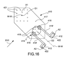
好ましい実施形態によれば、前記第1固定部411と前記第2固定部412とは、互いにオフセット距離d1だけ離間している。オフセット距離dは、動作状態にあるとき、垂直方向Z-Zに関して評価されてよく、その上流の電動マニピュレータ420、520に対する伝達部材410の向きに依存する。実施形態によれば、プレート413の少なくとも1つのエッジ473は、前記オフセット距離dに平行に配向される。
According to a preferred embodiment, the first
前記オフセット距離dは、前記電動マニピュレータ420、520から受けた操作動作が前記オフセット距離d1をずらして前記無菌アダプタ430、530に伝達されるように、前記局所近位-遠位方向W-Wと直交する方向に評価されてもよい。好ましくは、前記操作動作は、3つの相互に直交する方向X-X、Y-Y、Z-Zに沿って向けられる並進動作である。それによって、伝達部材410の下流側の局所的な近位-遠位方向W-Wは、伝達部材410の上流側の局所的な近位-遠位方向W-Wに対して前記オフセット距離d1だけオフセットされる。言い換えれば、前記第1固定部411で評価される局所的な近位-遠位方向W-Wは、前記第2固定部412で評価される近位-遠位方向W-Wに対して、前記オフセット距離d1のオフセットである。前記オフセット距離dの評価のために、前記第1固定部411及び/又は前記第2固定部412が所定のグローバル表面積A1及び/又はA2を有する場合、それぞれの固定部411及び/又は412は、前記所定のグローバル表面積A1及び/又はA2の評価幾何学的中心G1及び/又はG2である。
The offset distance d may be evaluated in a direction perpendicular to the local proximal-distal direction W-W such that the manipulation motion received from the
実施形態によれば、第1の固定部411のグローバル表面積A1及び第2の固定部412のグローバル表面積A2の相互の向きは、少なくとも1つの平面、例えば少なくとも水平面及び/又は垂直面において角度的にオフセットしている。好ましくは、第1固定部411のグローバル表面積A1と第2固定部412のグローバル表面積A2の相互の向きは、立体角ωを形成するように、少なくとも2つの平面[すなわち水平および垂直]において角度をもってオフセットされている。
According to an embodiment, the mutual orientations of the global surface area A1 of the first
実施形態によれば、前記部品本体415は、第1の固定部411のグローバル表面積A1と第2の固定部412のグローバル表面積A2との間に第1の角度オフセットを与えるのに適した少なくとも一つの剛体ロックジョイント418を有する。それによって、前記伝達部材410に対して遠位に評価される局所近位-遠位方向W-Wは、前記伝達部材410に対して近位に評価される前記局所近位-遠位方向W-Wに対して前記第1の角度オフセットの方向付けがされる。実施形態によれば、第2の固定部412は、ブラケット419、419'に取り付けられ、前記ブラケット419、419'は、順に、前記第1の固定部411に対して第2の角度オフセットの向きにされる。実施形態によれば、前記ブラケット419と前記第1の固定部411との間の距離d2は、前記オフセット距離d1よりも大きい。
According to an embodiment, the
実施形態によれば、前記部品本体415は、前記プレート413の前記第2表面417と前記第2固定部412とを接続する少なくとも1つのブラケット419、419'を備える。実施形態によれば、前記少なくとも1つのブラケット419、419'は、少なくとも1つの剛性ロックジョイント418を含み、前記剛性ロックジョイント418は、第1ブラケット部分419と第2ブラケット部分419'との間に介在される。実施形態によれば、距離d3は、前記第2表面417と前記ジョイント418との間に定義される 実施形態によれば、前記少なくとも1つの第2ブラケット部分419'は、前記第2固定部412を構成し、好ましくは「L」字形状である。ねじ接続要素などの固定手段を介してプレート413に一体的に接続された複数のブラケット部分419、419'を備えるおかげで、第1固定部411と第2固定部412の相互の位置と向きを調整するように、ブラケット部分419、419'とプレート413の相互の位置と向きを調整することが可能にされる。
According to an embodiment, the
実施形態によれば、「剛性的にロックされたジョイント418」は、剛性的にロックされたジョイントが相対的に可動な部分を欠いた剛性要素であることを意味し、相対的に可動な部分を欠いた当該剛性要素は、一体的に作られてもよい。実施形態によれば、"剛性的にロックされたジョイント418 "は、必ずしもブロック化されたロボット回転/プリズムジョイントを意味するものではない。 According to the embodiment, "rigidly locked joint 418" means that the rigidly locked joint is a rigid element lacking relatively movable parts, which may be made integrally. According to the embodiment, "rigidly locked joint 418" does not necessarily mean a blocked robotic rotary/prism joint.
実施形態によれば、前記部品本体415は、例えば図18に示すように、単一ピースの凸状固体要素として形成されている。
According to an embodiment, the
一般的な実施形態によれば、ロボットサージェリアセンブリ401が提供される。
According to a general embodiment, a
実施形態によれば、前記ロボットサージェリアセンブリ401は、上述した実施形態のいずれか1つによる少なくとも1つの伝達部材410を具備する。
According to an embodiment, the
前記ロボットサージェリアセンブリ401は、少なくとも1つの電動リニアスライダ423;424;425を含む少なくとも1つの電動マニピュレータ420、520を具備している。
The
実施形態によれば、前記少なくとも1つの電動リニアスライダ423、424、425は、それぞれのリニアガイド423'、424'、425'に対してスライドすることが好適である。
According to the embodiment, the at least one motorized
実施形態によれば、前記少なくとも1つの電動マニピュレータ420、520は、3つの電動リニアスライダ423、424、425からなり、前記電動リニアスライダの各々は、他の電動リニアスライダのスライド方向と直交する方向X-X、Y-Y、Z-Zに沿ってスライドすることが好適である。それにより、前記電動式マニピュレータ420、520は、直交電動式マニピュレータ420、520である。好ましい実施形態によれば、前記少なくとも1つの電動リニアスライダ423;424;425は、垂直ガイド425'に対して実質的に垂直方向Z-Zに沿ってスライドするのに適した、少なくとも1つの垂直スライダ425を有する。垂直リニアスライダ425と、2つの互いに直交する水平方向X-X、Y-Yに沿ってそれぞれスライドするのに適した2つの更なるスライダ423、424とを備えるおかげで、重力は垂直リニアスライダ425のスライドのみに影響を与える。それにより、電動マニピュレータの制御が簡素化される。また、自然な動作は、各スライダに対してそれぞれの動作を合成する必要がないため、さらに制御を簡略化することができる。
According to an embodiment, the at least one
実施形態によれば、前記垂直リニアスライダ425は、前記垂直リニアスライダ425に影響を及ぼす重力加速度を補償するためのカウンターウェイト426に関連付けられる。
According to an embodiment, the vertical
実施形態によれば、前記垂直リニアスライダ425は、前記少なくとも1つ、好ましくは3つの電動リニアスライダ423、424、425のうち最も遠位にあるスライダである。
According to an embodiment, the vertical
実施形態によれば、前記直交電動マニピュレータ420、520は、第1水平リニアガイド424'と、前記第1水平リニアガイド424'に対して第1水平方向Y-Yに沿ってスライドするのに適した第1水平電動リニアスライダ424とを有する。前記第1水平電動リニアスライダ424は第2水平リニアガイド423と一体である。前記直交電動マニピュレータ420、520は、前記第2の水平リニアガイド423'に関して第2の水平方向X-Xに沿ってスライドするのに適した第2の水平電動リニアスライダ423を含む。前記第2の水平電動リニアスライダ423は、前記垂直ガイド425'と一体である。前記垂直電動スライダ425は、前記垂直ガイド425'に関して垂直方向Z-Zに沿ってスライドするのに適している。
According to an embodiment, the orthogonal
実施形態によれば、前記一対の電動マニピュレータ420、520のうち第1の電動マニピュレータ420の1つ以上の電動リニアスライダ423;424;425は、前記一対の電動マニピュレータ420、520のうち第2の電動マニピュレータ520の1つ以上の電動リニアスライダ423;424;425に対し平行に配置されている。
According to the embodiment, one or more electric
好ましくは、両方の前記電動マニピュレータ420、520は、マクロ位置決め受動アーム450の同じリンク454に取り付けられる。
Preferably, both
前記垂直電動スライダ425に前記第1固定部411を介して固定された前記伝達部材410が設けられているおかげで、前記電動マニピュレータ420、520によって加えられる操作動作を、少なくとも前記オフセット距離d1の水平方向X-Xに並進させることができる。
Thanks to the
実施形態によれば、前記ロボットサージェリアセンブリ401は、手術器具440、540に接続するのに適した結合装置433を含む少なくとも1つの無菌アダプタ430、530を更に備える。実施形態によれば、前記無菌アダプタ430、530は、外科用ドレープ431と共に、無菌アダプタ430、530に近接したロボットサージェリアセンブリ401の部分と外科用器具440、540の間の相互汚染を妨げるのに適したドレーピングアセンブリ432を形成する。
According to an embodiment, the
実施形態によれば、局所的な近位-遠位方向はW-Wと定義され、単語「上流」は「近位」と同等の意味を持ち、単語「下流」は単語「遠位」と同等の意味を持つ。 According to an embodiment, the local proximal-distal direction is defined as W-W, where the word "upstream" is equivalent to the word "proximal" and the word "downstream" is equivalent to the word "distal."
実施形態によれば、前記伝達部材410は、前記少なくとも1つの電動マニピュレータ420、520と少なくとも1つの無菌アダプタ430、530との間に直接的又は間接的に介在される。それによって、前記伝達部材410は、前記電動マニピュレータ420、520の前記少なくとも1つの電動リニアスライダ423、424、425、好ましくは前記電動垂直リニアスライダ425と、前記無菌アダプタ430、530の前記結合装置433の相対相互位置及び/又は向きを剛性的に決定する。
According to an embodiment, the
好ましい実施形態によれば、モータボックスアセンブリ460が、前記伝動部品410と前記無菌アダプタ430、530との間に介在される。それにより、前記伝達部材410は、前記電動マニピュレータ420、520の前記少なくとも1つの電動リニアスライダ423、424、425と前記モータボックスアセンブリ460の相対的な相互位置および/または向きを剛性的に決定する。好ましい実施形態によれば、前記垂直電動スライダ425は、前記伝達部材の前記近位固定部411に接続された垂直スライダ435の遠位固定部を有する。それにより、前記伝達部材410は、前記垂直電動スライダ425を前記モータボックスアセンブリ460に接続する。
According to a preferred embodiment, a
実施形態によれば、前記ロボットサージェリアセンブリ401は、前記無菌アダプタ430、530の前記結合装置433に接続可能な少なくとも1つの外科手術器具440、540を備える。実施形態によれば、前記少なくとも1つの手術器具440、540は、前記無菌アダプタ430、530に着脱可能に接続可能である。実施形態によれば、前記少なくとも1つの外科用器具440、540は、シャフト441、541を備え、前記シャフト441、541は、好ましくは局所近位-遠位方向W-Wに沿って局所的に延びている。
According to an embodiment, the
それによって、前記シャフト441、541は、前記少なくとも1つの電動リニアスライダ423、424、425のスライド方向X-X、Y-Y、Z-Zに関してオフセットされている。実施形態によれば、 、前記シャフト441、541は、前記3つの電動リニアスライダ423、424、425の各々および全ての摺動方向X-X、Y-Y、Z-Zに関してオフセットされている。
Thereby, the
実施形態によれば、前記モータボックスアセンブリ460は、前記無菌アダプタ430、530に関して前記外科用器具440、540の少なくとも1つのそれぞれの自由度を作動させるために適した少なくとも1つのアクチュエータを備える。実施形態によれば、前記モータボックスアセンブリ460は、回転モータ461と、例えば伝達ベルト462を有するロールアクチュエータであって、シャフト441、541の長手方向展開軸を中心に、好ましくは局所近位-遠位方向W-Wを中心に前記シャフト441、541を有する前記外科用器具440、540を回動させるために好適なものと、を備えている。実施形態によれば、前記モータボックスアセンブリ460は、前記無菌アダプタ430、530を局所的な近位-遠位方向W-Wについて、好ましくは前記シャフト441、541の長手方向展開の軸について枢動させるのに適した回転モータ461およびロールアクチュエータ462を有する。好ましくは、前記外科用器具440、540は、前記無菌アダプタ430、530に接続されるとき、前記無菌アダプタ430、530と一体である。それにより、前記回転モータ461は、前記ドレーピングアセンブリ432に関して上流にある。
According to an embodiment, the
好ましい実施形態によれば、前記ロボットサージェリアセンブリ401は、一対の電動マニピュレータ420、520を形成する2つの電動マニピュレータ420、520を有する。それにより、前記ロボットサージェリアセンブリ401は、第1の電動マニピュレータ420及び第2の電動マニピュレータ520を有する。実施形態によれば、各電動マニピュレータ420、520は、前記少なくとも2つの電動マニピュレータ420、520のそれぞれを個別に包むケース427、527を有する。それにより、前記ロボットサージェリアセンブリ401は、2つのケース427、527、即ち、第1のケース427及び第2のケース527を有する。
According to a preferred embodiment, the
好ましい実施形態によれば、前記2つの電動マニピュレータ420、520は共に、水平方向X-Xにおいて互いに側面となるように、実質的に同じ高さでマクロ位置決めアーム450が固定されている。実施形態によれば、各電動マニピュレータ420、520は、前記マクロ位置決めアーム450に固定するための固定部451、例えば、固定ブラケットを備える。実施形態によれば、前記固定部451は、前記リニアガイド423'、424'、425'のうちの1つと一体であり、好ましくは水平リニアガイド423'、424'に、より好ましくは前記第2水平リニアガイド424'に一体である。
According to a preferred embodiment, the two
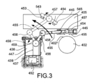
好ましい実施形態によれば、前記各ケース427、527は、前記伝達部材410の少なくとも1つを包囲する。実施形態によれば、前記各ケース427、527は、近位ケース部分428、528と、前記近位ケース部分428、528に関して遠位の遠位ケース部分429、529とを含み、前記近位ケース部分428、528は、それぞれの電動マニピュレータ430、530を包含し、前記遠位ケース部分429、529は、それぞれの伝達部材410を包含している。
According to a preferred embodiment, each of the
電動マニピュレータ420、520の下流に前記伝達部材410をそれぞれ設けることにより、外科用器具440、540の2つのシャフト441、541は、一方が他方に向かって収束している。それによって、各シャフト441、541の遠位端442、542は、同じ共有作業ボリューム404に到達する。各シャフト441、541の遠位端には、患者に手術を行うのに適した先端部分を有するロボット手術用の手首のような、例えばエンドエフェクタなどの多関節端末ツール475が設けられていてもよい。実施形態によれば、各シャフト441、541の遠位端に設けられた前記多関節端末ツール475は、1つ以上の自由度P、Y、G、好ましくは少なくとも1つのピッチP自由度、少なくとも1つのヨーY自由度、及び少なくとも1つのグリップG自由度を有している。実施形態によれば、前記多関節端末工具475は、互いに関節結合された複数のリンク476,477,478,479と、多関節端末工具475のリンク476,477,478,479の自由度P,Y,Gを作動させる複数の作動ケーブル480,481,482を有する。各リンク476,477,478,479は、好ましくは、ワイヤ放電加工によって一体に作られる。作動ケーブル480,481,482は、前記リンク476,477,478,479の凸状外面に摺接する。
By providing the
実施形態によれば、各ケース427,527は、それぞれの電動マニピュレータ420,520及び伝動部品401に可能な限り密着し、それぞれの近位ケース部分428,528と遠位ケース部分429,529との間にエルボを形成している。それにより、2つのケース427、527は、それに遠位に取り付けられた外科用器具440、540のシャフト441、541が、その遠位端442、542で前記共有作業ボリューム404に達するように、互いに向かい合う凹部[即ちエルボ]を有している。
According to an embodiment, each
実施形態によれば、第1のシャフト441の遠位端442は第1の作業ボリューム403に達し、第2のシャフト541の遠位端542は第2の作業ボリューム503に達する。前記第1の作業ボリューム403及び前記第2の作業ボリューム503は、一緒になって前記共有作業ボリューム404を定義する。前記共有作業ボリューム404は、スライダ523、524、525の任意の動作位置について、各シャフト441、541の遠位部分442、542によって、到達することが可能である。言い換えれば、共有作業ボリューム404は、第1作業ボリューム403と第2作業ボリューム503の交わる体積によって与えられる。
According to an embodiment, the
前記スライダが設けられているおかげで、各作業ボリューム403、503は、それぞれの電動マニピュレータ420、520のスライダ423、424、425のスライド方向X-X、Y-Y、Z-Zに平行である。前記垂直スライダ425と前記水平スライダ423,424が設けられているおかげで、同じ共有作業ボリューム404は、水平平行六面体である。本明細書で使用される単語「平行六面体」は、同じ共有作業ボリューム404が立方体である場合をも包含する。好ましくは、前記同一の共有作業ボリューム404は、前記第1及び第2の作業ボリューム403、503の各々の少なくとも50%であり、好ましくは、前記第1及び第2の作業ボリューム403、503の各々の少なくとも3分の2であり、より好ましくは、実質的に90%である。実施形態によれば、前記第1及び第2の作業ボリューム403、503は、完全に一緒になって、単一の共有作業ボリューム404を形成する。
Thanks to the provision of said sliders, each working
このようなロボット手術システムのおかげで、シャフト441、541の両方の遠位端は、共有作業ボリュームに到達し、前記共有作業ボリューム内で互いに平行に移動することが可能である。
Thanks to such a robotic surgical system, the distal ends of both
操作者、例えばマスタコンソールからスレーブロボットサージェリアセンブリを制御する外科医は、それによって、シャフトの一方または両方が共有作業ボリュームの境界に到達したことを感じることができる。このようにして、外科医のための快適さが強化される。 An operator, e.g., a surgeon controlling the slave robotic surgery assembly from the master console, can thereby feel when one or both of the shafts have reached the boundary of the shared working volume. In this way, comfort for the surgeon is enhanced.
好ましい実施形態によれば、前記ケース427、527は、水平方向X-X、Y-Y、好ましくは前記第1の水平方向X-Xに沿って、予め定められた水平距離X2の範囲で互いに離間されている。好ましい実施形態によれば、前記予め定められた水平距離X2は、前記オフセット距離d1よりも大きい。好ましい実施形態によれば、前記所定の水平距離X2は、前記オフセット距離d1の2倍よりも大きい。
According to a preferred embodiment, the
前記所定の水平距離X2は、局所的な近位-遠位方向W-Wに沿って変化してもよい。好ましい実施形態によれば、前記所定の水平距離X2は、それぞれの電動マニピュレータ430、530を包む近位ケース部分428、528において、それぞれの伝達部材410を包む遠位ケース部分429、529より大きい。それによって、予め定められた水平距離X2は、好ましくは、無菌アダプタに向かって下流に向かうにつれて減少する。
The predetermined horizontal distance X2 may vary along the local proximal-distal direction W-W. According to a preferred embodiment, the predetermined horizontal distance X2 is greater in the
有利には、窓434又は通路434が、前記2つのケース427、527によって少なくとも部分的に区切られる。好ましくは、前記窓434は、第1の水平方向X-Xにおいて前記2つのケース427、527によって区切られる。前記窓434が設けられることにより、前記2つの電動マニピュレータ420、520の間に第2の水平方向Y-Yに沿った貫通路が形成される。前記窓434のおかげで、前記電動マニピュレータ420、520を包むケース427、527の間に、自由にしておいてもよい容積が提供される。前記窓434は、好ましくは、第1の水平方向X-Xにおける予め定められた水平距離X2と同じ幅である。
Advantageously, a
前記窓434を区画する前記それぞれのケース427、527内に包含される2つの電動マニピュレータ420、520の相互位置及び向きのおかげで、外科医402は、マニピュレータ420、520が結果として外科医の402肩402'の上に位置するように前記窓434の後ろの位置を占め得る。
Due to the relative position and orientation of the two
実施形態によれば、前記ロボットサージェリアセンブリ401は、共有作業ボリューム404の拡大画像を外科医に提供するのに適したビジョンデバイス472に接続された画像取得部471を含む顕微鏡アセンブリ470に関連付けられる。ビジョンデバイス472は、好ましくは、少なくとも1つの眼球、好ましくは1対の眼球を有する。好ましい実施形態によれば、前記画像取得部471は、マイクロサージェリ用の光学顕微鏡である。ビジョンデバイス472の少なくともオキュラーをドレープするために、顕微鏡ドレープが設けられてもよい。
According to an embodiment, the
例えば図9に示すような好ましい実施形態によれば、顕微鏡アセンブリ470の前記少なくとも1つの眼球472は、少なくとも部分的に前記窓434内にある。それによって、前記少なくとも1つの眼球472は、前記ケース427、527の間にある。
According to a preferred embodiment, for example as shown in FIG. 9, the at least one
各ケース427、527内の前記伝達部材410の提供のおかげで、手術器具440、540のシャフト441、541が、その遠位端442、542を第2の水平方向Y-Yに沿って垂直スライダ425に対して前進した位置に向ける互いの方へ収束するように、第2の水平方向Y-Yに沿って角度のオフセットをも提供される。それによって、共有作業ボリューム404は、外科医402に対して前方に位置する手術台405の上又は上にある。それによって、外科医402は、眼球472を見るロボット支援マイクロサージェリおよび前記手術台405上の患者の解剖学的構造を直接下方に見る従来の手のマイクロサージェリを交互に行うことができる。術者402が手術状態で窓434に面するとき、第2の水平方向Y-Yは術者402の矢状面に実質的に平行である。
Thanks to the provision of the
上記のように各ケース427、527内の前記伝達部材410の提供のおかげで、眼球427、527は手術用器具440、540の上に表れ、手術用器具440、540は順番に手術台405の上に存在する。術者402は、手術台に対して正面から[すなわち第2の水平方向Y-Yに沿って]接近する。手術器具440、540のシャフト441、541は、共に、その遠位端442、542が共有作業ボリューム404に正面から[すなわち第2の水平方向Y-Yに沿って]、上方から[すなわち垂直方向Z-Zに沿って]近づき、第1の水平方向X-X[すなわち横方向]に互いに向かって収束している。それによって、ロボット手術システム401のボリューメトリック・エンカンバーは、外科医402が、自分の視線を向けるだけで、顕微鏡アセンブリ470の眼球472の有無にかかわらず、共有作業ボリューム404及び患者の解剖学の関連部分を自分の眼402''で見ることができるようにする。言い換えれば、ロボット手術システム401の容積的な包囲は、前記ケース427、527内に包まれた伝達部材401のおかげで、外科医の視線から作業容積404を隠すことを回避している。
Thanks to the provision of the
実施形態によれば、前記ロボット手術システム401は、マクロ位置決めアーム450を具備する。
According to an embodiment, the robotic
好ましくは、前記マクロ位置決めアーム450は、受動的に移動させることができ、その位置決めのためのモータを必要としない。それによって、マクロ位置決めアーム450は、オペレータ、例えば外科医402及び/又は外科エクイップのメンバーによってマクロ位置決めアーム450を手で操作するための少なくとも1つのハンドル453を有する。マクロ位置決めアーム450の変位を減衰させるために、回転ジョイント内にダイナミックブレーキが設けられてもよい。
Preferably, the
実施形態によれば、前記マクロ位置決めアーム450は、互いに直列に接続され、回転ジョイント457、458、459を介して関節運動する複数のアームリンク454、455、456を有する。それによって、前記マクロ位置決めアーム450は、実質的に水平に向けられた細長い遠位リンク本体を有し、遠位回転ジョイント457を介して第2リンク455に近位に接続された最遠位リンク454、すなわち第1リンク454を有する。好ましくは、前記遠位回転ジョイント457は、遠位リンク454が遠位回転ジョイント457の周りで枢動し得るように、遠位リンク454の中心部分444に実質的に接続される。好ましくは、中央部分444は、遠位リンク454の長さの半分のところにある 好ましい実施形態によれば、遠位回転ジョイント457の軸は、垂直に配向される。
According to an embodiment, the
実施形態によれば、前記マクロ位置決めアーム450は、前記一対の電動マニピュレータ420、520に接続された前記遠位リンク454と、前記遠位リンク454に近接して、回転軸が実質的に垂直な前記遠位回転ジョイント457を介して前記遠位リンク454に接続された第2のリンク455とを具備し、前記遠位リンク454に近接する前記遠位リンク455は、回転軸が前記遠位回転ジョイント457に近接して、回転軸が垂直な前記遠位回転ジョイント457を具備する。および、前記第2リンク455に近接して、回転軸が実質的に垂直である第2回転ジョイント458を介して前記セコンドリンクに接続された第3リンク456からなり、前記第2リンク455は水平に方向付けられ、前記遠位リンク454および前記第1リンク456が実質的に同じ高さにあるように、前記セコンドリンク454と前記第1リンク456との両方の上に延びていることを特徴とする。好ましい実施形態によれば、前記第3リンク456は、第3回転ジョイント459を介して、手術台405及び外科医402に対するマクロ位置決めアーム450の高さを調整するために垂直方向Y-Yに伸長するのに適した伸縮自在な伸縮部分446に接続され、ロボットサージェリアセンブリ401はロボット台車447又はタワー447を更に備え、前記伸縮自在部分446は前記台車447に対して伸縮自在である。実施形態によれば、前記台車447は、車輪448のような地面接触ユニット448を含んでいる。前記マクロ位置決めアーム450及び前記台車447の少なくとも一部をドレープするために、少なくとも1つの外科用ドレープ431が設けられていてもよい。台車447は、台車447を手術用ベッド405の周囲内で移動させるための少なくとも1つの台車ハンドル449を具備してもよい。実施形態によれば、前記マクロ位置決めアーム450は、前記ロボット台車447に接続されている。
According to an embodiment, the
実施形態によれば、前記遠位リンク454は、1つの電動マニピュレータ420、520に、好ましくはそれぞれの電動マニピュレータ430、530の固定部451に接続するのに適した2つの取付部445、545をそれぞれさらに備え、遠位回転ジョイント457は、遠位リンク454の取付部445、545間にあるので、遠位リンク454を枢動ジョイント457に対して枢動角の枢動操作P4が行われるようにされている。例えば実質的に180度又は半回転を測定する枢動角度によって、電動マニピュレータ420、520が、例えばマクロ位置決めアーム450の第2のリンク455に関して、及び/又は台車477に関して、及び/又は外科医402、及び/又は手術台405に関して、それらの位置を反転するように決定される。
According to an embodiment, the
好ましい実施形態によれば、遠位リンク454の取付部445、545の位置は、遠位回転ジョイント457に対して対称的に配置されている。言い換えれば、好ましくは垂直である遠位回転ジョイント457の回転軸と、第1の電動マニピュレータ420、520に接続する第1の取付部445との間の第1の距離X4は、遠位回転ジョイント457の回転軸と第2の取付部545との間の第2の距離X5と等しい。それによって、マクロ位置決めアーム450の下流のロボット要素の動的及び静的バランスが、動作状態におけるその安定性を向上させるように強化される。
According to a preferred embodiment, the positions of the mounting
好ましい実施形態によれば、遠位リンク454と、それぞれのケース427、527内に封入された電動マニピュレータ420、520は、前記窓434を上方および横方向に一緒に区切る。好ましい実施形態によれば、遠位リンク454およびそれぞれのケース427、527内に封入された電動マニピュレータ420、520は、前記窓434を部分的に区切る「逆U」字型の構造を形成している。言い換えれば、遠位リンク454と、それぞれのケース427、527内に封入された電動マニピュレータ420、520は、部分的に前記窓434を区切る馬蹄形構造を形成する。実施形態によれば、前記少なくとも2つの電動マニピュレータ420、520の両方は、マクロ位置決め受動アーム450の同じリンク454に取り付けられる。
According to a preferred embodiment, the
実施形態によれば、ロボット台車447は、第1の側面437及び第2の側面438を備え、第1の側面437及び第2の側面438は、前記伸縮自在部分446に対して水平方向で互いに対向し、好ましくは、前記第1の水平方向X-Xで互いに対向している。前記遠位リンク454がその中央部444において前記第2リンク455に接続されている前記複数のリンク454、455、456を接続して関節運動させる前記複数の回転ジョイント457、458、459を有する前記マクロ位置決めアーム450と、前記反対側面437、438を有するロボット台車477とを組み合わせて設けることにより、共有作業ボリューム404を前記第1側面437または前記第2側面438のいずれかに向けて配置することができ、ロボット手術組立体401の多様性が改善されている。それによって、ロボット台車477は、手術室ベッド405に対して実質的に任意の位置に配置することができる。それにより、外科医402は、ロボット台車477と手術室のベッドの任意の相互位置において、前記窓434に向かい、前記窓434を通して患者の解剖学的構造にアクセスでき、一方、手術器具440、540のシャフト441、541の遠位端442、542は常に手術室のベッド405に正面から近づき、マニピュレータ420、520は外科医402に対し同じ水平位置にある。
According to an embodiment, the
実施形態によれば、台車477は、多角形の形状を有し、複数のコーナー部分436を形成する頂部周囲435を規定する頂部439を備え、前記マクロ位置決めアーム450が前記コーナー部分436の1つに接続されている。前記台車477の頂部部分439は、前記ロボットサージェリアセンブリ401の状態に関する情報を表示するためのスクリーン452を含んでいてもよい。
According to an embodiment, the
実施形態によれば、前記ロボットサージェリアセンブリ401は、前記少なくとも1つの手術器具440、540、前記電動マニピュレータ420、520、及び前記少なくとも1つのモータボックスアセンブリ460によって形成されるロボットスレーブ部分407を備える。実施形態によれば、前記ロボットサージェリアセンブリ401は、手動コマンドを検出するのに適した少なくとも1つのマスタ入力ツール465、565と、例えば前記手術器具440、540の少なくとも1つ及び/又は前記電動マニピュレータ420、520の少なくとも1つを起動するのに適したロボット407の前記スレーブ部分とを備えるマスタコントローラアセンブリ406を具備している。例えば、前記少なくとも1つのマスタ入力ツール465、565の位置および向きは、ロボット407の前記スレーブ部分に制御信号を送信するために、前記フィールド内の少なくとも位置および好ましくは前記マスタ入力ツール465、565の向きも検出する目的で、フィールドを発生するフィールド発生器443を含む電磁および/または光学追跡装置により追跡される。
According to an embodiment, the
実施形態によれば、前記マスタコントローラアセンブリ406は、外科用椅子464と、前記外科用椅子434をドレープし、好ましくは前記少なくとも1つのマスタ入力ツール465、565もドレープするマスタドレープアセンブリ467とを備える無菌コンソール463を更に備える。実施形態によれば、前記手術用椅子464は、外科医の手によって把持されたときにマスタ入力ツール465、565のための運動の自由度の円錐469、569を規定するように、外科医402が手術中にその上に肘を置くための、例えばドーム形の少なくとも一つの静止要素468、568を有する。手によるマイクロサージェリおよびロボット支援マイクロサージェリの交代を促進する目的で、外科医402が少なくとも1つのマスタ入力ツール465、565を落とすためのドロップホルスター474、574も、マスタコントローラアセンブリ406に提供されてもよい。手の手術ツール466、566はまた、手のマイクロサージェリおよびロボット支援マイクロサージェリを交互に行うために外科医402を促進するために、マスタコンソールアセンブリ406で提供され得る。
According to an embodiment, the
好ましくは、2つのマスタ入力ツール465、565が設けられ、各マスタ入力ツールは、ロボットシステムの1つのブランチを制御し、各ブランチは、前記電動マニピュレータの1つとそれに取り付けられた下流の要素とを含む。
Preferably, two
一般的な実施形態によれば、手術室アリーナ408は、上述の実施形態のいずれか1つによる少なくとも1つのロボットサージェリアセンブリ401と、上述の実施形態のいずれか1つによる手術室テーブル405と、上述の実施形態のいずれか1つによる顕微鏡アセンブリ470と、を備える。当業者であれば理解できるように、「手術台」は、手術中に患者を支持する任意の場所を意味する。
According to a typical embodiment, the
実施形態によれば、前記手術室アリーナ408は、上述した実施形態のいずれか1つによるマスタコントローラアセンブリ406を有する。好ましくは、2つのマスタ入力ツールが提供され、各マスタ入力ツールは、ロボットシステムの1つのブランチを制御し、各ブランチは、前記電動マニピュレータの1つとそれに取り付けられた下流の要素とを含んでいる。
According to an embodiment, the
一般的な動作モードによれば、上述の実施形態のいずれか1つによる手術場アリーナ408内のロボットサージェリアセンブリ401のスレーブロボット部品407の再位置決め方法は、以下のステップを備える。
According to a general mode of operation, a method for repositioning a
この方法は、電動マニピュレータ420、520がマクロ位置決めアーム450の第2のリンク455に対して位置を反転させるように、遠位リンク454を旋回角の遠位回転ジョイント457を中心に旋回させる旋回動作P4を発揮させるステップを含む。
The method includes a step of exerting a pivoting motion P4 in which the
可能な動作モードによれば、本方法は、前記遠位リンク454をロボット台車477の側面または反対側のいずれかに向かわせるように、前記遠位回転ジョイント457に並進動作T4を及ぼすステップを含む、方法。
According to a possible mode of operation, the method includes exerting a translational motion T4 on the distal rotary joint 457 to move the
可能な動作モードによれば、本方法は、前記マクロポジショニングアーム450を前記ロボット台車477に対して、好ましくは垂直軸を有する回転ジョイントを中心に枢動させるステップを含む。
According to a possible mode of operation, the method includes pivoting the
本方法は、前記共有作業ボリューム404を手術台405上又はその上に維持しながら、前記ロボット台車477を手術台405に対して再位置決めするステップを具備する。
The method includes repositioning the
特定の実施形態において、ばらばらに又はその任意の組み合わせで提供される上述の特徴によって、上述の利点を提供する上述のニーズに対応することが可能であり、特にそうである。 In certain embodiments, the above-mentioned needs may be addressed, and in particular, by the above-mentioned features provided separately or in any combination thereof, providing the above-mentioned advantages.
外科用器具のシャフトは、互いに向かって収束する。 The shafts of the surgical instruments converge towards each other.
外科用器具のシャフトがスライダに対して平行でない。 The shaft of the surgical instrument is not parallel to the slider.
各電動マニピュレータのスライダはそれぞれ平行である。 The sliders of each electric manipulator are parallel to each other.
共有された作業ボリュームは、シャフトの遠位端、及びそれにそれぞれ取り付けられたエンドエフェクタによって、前方、上方及び側方に最大化され、接近される。 The shared working volume is maximized and approached forward, upward, and laterally by the distal ends of the shafts and their respective attached end effectors.
ロボットのスレーブ部分の容積的な包囲は、顕微鏡と患者の解剖学的構造の両方が見えるように、外科医が手術場アリーナ内で彼・それ自身を位置づけることを可能にする。 The volumetric enclosure of the robotic slave part allows the surgeon to position himself within the operating arena so that he can see both the microscope and the patient's anatomy.
外科医は、最小限の労力で、別の場所に座る/立つことを必要とせずに、手によるマイクロサージェリからロボット支援マイクロサージェリに切り替えることを許される。 Surgeons are allowed to switch from manual to robotic microsurgery with minimal effort and without the need to sit/stand in a separate location.
外科医は、ロボット台車の右側または左側のいずれかに位置することができる。 The surgeon can be positioned on either the right or left side of the robotic cart.
受動的な(すなわち、電動自由度のない)マクロ位置決めアームは、その回転ジョイントに設けられたブレーキのおかげで、手術中にも移動させることができる。 The passive (i.e., no motorized degrees of freedom) macropositioning arm can be moved during surgery thanks to brakes on its rotational joints.
ロボットのスレーブ部分は、垂直方向に関して対称に作られている。 The slave part of the robot is made symmetrical in the vertical direction.
当業者は、上述した実施形態に対して多くの変更および適応を行うことができ、あるいは、添付の請求項の範囲から逸脱することなく、偶発的なニーズを満たすために、機能的に同等である他の要素に置き換えることができる。 Those skilled in the art may make numerous modifications and adaptations to the above-described embodiments, or may substitute other functionally equivalent elements to meet their foreseeable needs, without departing from the scope of the appended claims.
401 ロボット手術用アセンブリ
402 外科医
402' 外科医の肩
403、503 作業量
404 共有作業量
405手術台又は手術用ベッド
406 マスタコンソールアセンブリ
407 スレーブアセンブリ
408 オペラトリーアリーナ
410 伝達部材
411 トランスミッションコンポーネントの第1固定部
412 トランスミッションコンポーネントの第2固定部
413 プレート
414 厚さ
415 伝達部材本体又は部品本体
416 プレートの近位面
417 プレート遠位面
418 伝達部材の継手
419, 419' 伝達部材のブラケット
420、520 電動式マニュピレータ
421近位固定手段
422 遠位固定手段
423 第2の水平方向電動スライダ
424 第1の水平方向電動スライダ
425 垂直方向電動スライダ
426 カウンターウェイト
427、527 ケース
428、528 ケースの近位部
429, 529 ケース遠位部
430, 530 無菌アダプタ
431 手術用ドレープ
432 ドレーピングアセンブリ
433 無菌アダプタの遠位連結部
434 窓または通路
435 多角形の外周
436 台車の上部の角部分
437 台車の第1の側部
438 台車の第2の反対側
439 台車の上端部
440,540 手術用器具
441,541 シャフト
442, 542 シャフト遠位端
443磁場発生装置
444 遠位リンクの中央部
445、545 遠位リンクの取付部
446 テレスコープ状に伸びる部分
447 ロボット台車又はタワー
448 ロボット台車の接地ユニット又は車輪
449 ロボット台車のハンドル
450 マクロ位置決めアーム
451 電動式マニピュレータの固定部
452 スクリーン
453 マクロポジショニングアームのハンドル
454 マクロポジショニングアームの第1リンクの遠位リンク
455 マクロポジショニングアームの第2リンク
456 マクロポジショニングアームの第3のリンク
457 マクロポジショニングアームの遠位回転ジョイント又は第一ジョイント
458 マクロポジショニングアームの第2回転継手
459 マクロポジショニングアームの第3回転継手
460 モータボックスアセンブリ
461 回転モータ
462 伝達ベルト
463 無菌コンソール
464 サージカルチェア
465, 565 マスタ入力ツール
466, 566 ハンドサージェリツール
467 マスタドレープ
468, 568 安静要素
469, 569 自由度コーン
470 顕微鏡アセンブリ
471 顕微鏡の画像取得部
472 視覚装置
473 エッジ
474, 574 ドロッピングホルスター
476, 477, 478, 479 多関節端末ツールのリンク
480、481、482 多関節端末工具の作動ケーブル
P ピッチ
Y Yaw
G グリップ
X-X 第1の水平方向
Y-Y 第2の水平方向又は前方方向
Z-Z 垂直方向
W-W 局所的な近位-遠位方向
A1 第1の固定部の全面積
A2 少なくとも1つの第2の固定部のグローバル表面積
G1 第1の固定部のグローバル表面積の幾何学的中心
G2 第2の固定部のグローバルサーフェスエリアの幾何学的中心
d1 透過部材のオフセット距離
X2 あらかじめ定義された水平距離
X4 第1距離
X5 第 2 距離
P4 首振り動作
T4 並進動作
Ω 立体角
401 Robotic Surgery Assembly
402 Surgeon
402'Surgeon's Shoulder
403, 503 Workload
404 Shared amount of work
405 Operating table or operating bed
406 Master Console Assembly
407 Slave Assembly
408 Opera Arena
410 Transmission parts
411 Transmission component first fixing part
412 Secondary fixing part of transmission component
413 Plate
414 Thickness
415 Transmission member body or part body
416 Proximal surface of plate
417 Distal surface of plate
418 Transmission component joint
419, 419' Transmission member bracket
420, 520 Electric Manipulator
421 Proximal fixation means
422 Distal fixation means
423 Second horizontal motorized slider
424 First horizontal motorized slider
425 Vertical Motorized Slider
426 Counterweight
427, 527 cases
428, 528 Proximal part of case
429, 529 Case distal part
430, 530 Sterile Adapter
431 Surgical Drapes
432 Draping Assembly
433 Distal connection of sterile adapter
434 Windows or passageways
435 Periphery of a Polygon
436 Upper corner of the trolley
437 First side of the carriage
438 Second opposite side of the trolley
439 Top end of the trolley
440,540 Surgical instruments
441, 541 Shaft
442, 542 Distal end of shaft
443 Magnetic Field Generator
444 Central part of distal link
445, 545 Distal link attachment
446 Telescopic extension
447 Robot cart or tower
448 Ground unit or wheel of robot cart
449 Robot Cart Handle
450 Macro Positioning Arm
451 Fixing part of electric manipulator
452 screens
453 Macro Positioning Arm Handle
454 Distal link of first link of macro positioning arm
455 Macro Positioning Arm 2nd Link
456 Third Link of Macro Positioning Arm
457 Distal rotation joint or first joint of macro positioning arm
458 Macro Positioning Arm Second Rotary Joint
459 Macro Positioning Arm Third Rotary Joint
460 Motor Box Assembly
461 Rotary Motor
462 Transmission Belt
463 Sterile Console
464 Surgical Chair
465, 565 Master Input Tool
466, 566 Hand Surgery Tools
467 Mustard Drape
468, 568 Rest element
469, 569 degrees of freedom cone
470 Microscope Assembly
471 Microscope Image Acquisition Unit
472 Visual Devices
473 Edge
474, 574 Dropping Holster
476, 477, 478, 479 Articulated Terminal Tool Links
480, 481, 482 Actuating cables for articulated end tools
Pitch
Y Yaw
G Grip
XX First horizontal
YY Second horizontal or forward direction
ZZ vertical direction
WW Local proximal-distal direction
A1 Total area of the first fixing part
A2 the global surface area of at least one second fastening part
G1 Geometric center of global surface area of first fixed part
G2 Geometric center of the global surface area of the second fixed part
d1 Offset distance of transparent member
X2 Predefined horizontal distance
X4 1st distance
X5 2nd distance
P4 Swinging motion
T4 Translational motion Ω Solid angle
Claims (15)
マクロ位置決め受動アーム(450)と、
一対の電動マニピュレータ(420、520)であって、
前記一対の電動マニピュレータ(420、520)のそれぞれが、互いに直交する3つの電動リニアスライダ(423、424、425)を含み、
前記一対の電動マニピュレータ(420、520)の一方の電動マニピュレータ(420)の前記3つの電動リニアスライダ(423、424、425)が、前記一対の電動マニピュレータ(420、520)の他方の電動マニピュレータ(520)の前記3つの電動リニアスライダ(423、424、425)に平行で、
前記一対の電動マニピュレータ(420、520)は共に、前記マクロ位置決め受動アーム(450)の同じリンク(454)に取り付けられている、一対の電動マニピュレータ(420、520)と、
一対の無菌アダプタ(430、530)であって、前記一対の無菌アダプタ(430、530)のそれぞれは、一対の手術器具(440、540)に接続するのに適した結合装置(433)を含む、一対の無菌アダプタ(430、530)と、
前記一対の無菌アダプタ(430、530)にそれぞれ接続された前記一対の手術器具(440、540)であって、前記一対の手術器具はそれぞれシャフト(441、541)を備える、一対の手術器具(430、530)と、
一対の伝達部材(410)であって、前記一対の伝達部材(410)はそれぞれが、
前記一対の電動マニピュレータ(420、520)のうちの少なくとも1つの電動マニピュレータ(420、520)に剛性的に接続するのに適した第1の固定部(411)と、
前記一対の無菌アダプタ(430、530)のうちの少なくとも1つの無菌アダプタ(430、530)に剛性的に接続する第2の固定部(412)と、
前記第1の固定部(411)と前記第2の固定部(412)との間で、前記第1の固定部(411)及び前記第2の固定部(412)をそれぞれの相互位置に保持する部品本体(415)とを備えた、一対の伝達部材(410)とを含み、
前記一対の伝達部材(410)のそれぞれの前記部品本体(415)は、前記第1の固定部(411)及び前記第2の固定部(412)を第1の水平方向(X-X)にオフセット距離(d1)だけ間隔をあけて、前記一対の電動マニピュレータ(420、520)から受けた操作動作が前記オフセット距離(d1)をずらして前記一対の無菌アダプタ(430、530)に伝達され、
前記一対の伝達部材(410)のそれぞれの前記部品本体(415)は、前記一対の伝達部材(410)のそれぞれの前記第1の固定部(411)と前記第2の固定部(412)との間に、前記第1の水平方向(X-X)及び前記第1の水平方向(X-X)と直交する第2水平方向(Y-Y)に立体角(Ω)を形成する角度オフセットを与える少なくとも一つの剛性のロックジョイント(418)を有し、
前記一対の伝達部材(410)はそれぞれ、前記一対の電動マニピュレータ(420、520)の一方と前記一対の無菌アダプタ(430、530)のそれぞれとの間に介在されて、前記一対の電動マニピュレータ(420、530)の前記3つの電動リニアスライダ(423、424、425)と前記一対の無菌アダプタ(430、530)の前記結合装置(433)との相対相互位置及び向きを決定し、
前記一対の手術器具(440、540)のそれぞれの前記シャフト(441、541)は、前記一対の電動マニピュレータ(420、520)の前記3つの電動リニアスライダ(423、424、425)のそれぞれ及び全てのスライド方向(X-X、Y-Y、Z-Z)にオフセットされ、
前記一対の手術器具(440、540)のそれぞれの前記シャフト(441、541)は、それぞれの遠位端(442、542)を前方に向けて互いに収束して延びており 、
前記一対の電動マニピュレータ(420、520)はそれぞれ、前記一対の電動マニピュレータ(420、520)のそれぞれを個別に包む2つのケース(427、527)を含み、
前記2つのケース(427、527)は、窓(434)が前記2つのケース(427、527)によって少なくとも部分的に区画されるように、前記第1の水平方向(X-X)に沿って予め定められた水平距離(X2)だけ互いに離間され、
前記窓(434)は、外科医(402)が前記窓(434)の後ろに位置を占めたときに、前記一対の電動マニピュレータ(420、520)が外科医の肩(402’)の上に位置するように設計されている、ロボットサージェリアセンブリ(401)。 A robotic surgery assembly (401) for robotic assisted microsurgery, comprising:
A macro positioning passive arm (450);
A pair of electric manipulators (420, 520),
Each of the pair of electric manipulators (420, 520) includes three mutually orthogonal electric linear sliders (423, 424, 425);
the three electric linear sliders (423, 424, 425) of one electric manipulator (420) of the pair of electric manipulators (420, 520) are parallel to the three electric linear sliders (423, 424, 425) of the other electric manipulator (520) of the pair of electric manipulators (420, 520);
a pair of motorized manipulators (420, 520), both of which are attached to the same link (454) of the macropositioning passive arm (450);
a pair of sterile adaptors (430, 530), each of said pair of sterile adaptors (430, 530) including a coupling device (433) suitable for connection to a pair of surgical instruments (440, 540);
a pair of surgical instruments (440, 540) respectively connected to a pair of sterile adapters (430, 530), each of the pair of surgical instruments having a shaft (441, 541);
A pair of transmission members (410), each of the pair of transmission members (410) being:
a first fixed part (411) suitable for rigidly connecting to at least one electric manipulator (420, 520) of the pair of electric manipulators (420, 520);
a second fixing portion (412) rigidly connected to at least one of the pair of sterile adapters (430, 530);
a pair of transmission members (410) including a component body (415) between the first fixed portion (411) and the second fixed portion (412) for holding the first fixed portion (411) and the second fixed portion (412) in their respective relative positions;
The component bodies (415) of each of the pair of transmission members (410) are spaced apart from the first fixing portion (411) and the second fixing portion (412) by an offset distance (d1) in a first horizontal direction (X-X), and an operating motion received from the pair of electric manipulators (420, 520) is transmitted to the pair of sterile adapters (430, 530) by shifting the offset distance (d1),
Each of the component bodies (415) of the pair of transmission members (410) has at least one rigid lock joint (418) between the first fixed portion (411) and the second fixed portion (412) of each of the pair of transmission members (410), the rigid lock joint (418) providing an angular offset that forms a solid angle (Ω) in the first horizontal direction (X-X) and a second horizontal direction (Y-Y) perpendicular to the first horizontal direction (X-X),
Each of the pair of transmission members (410) is interposed between one of the pair of electric manipulators (420, 520) and each of the pair of sterile adapters (430, 530) to determine the relative mutual positions and orientations of the three electric linear sliders (423, 424, 425) of the pair of electric manipulators (420, 530) and the coupling device (433) of the pair of sterile adapters (430, 530);
the shafts (441, 541) of each of the pair of surgical instruments (440, 540) are offset in each and every sliding direction (X-X, Y-Y, Z-Z) of the three electric linear sliders (423, 424, 425) of the pair of electric manipulators (420, 520);
The shafts (441, 541) of the pair of surgical instruments (440, 540) extend toward each other and converge toward each other with their respective distal ends (442, 542) facing forward,
Each of the pair of electric manipulators (420, 520) includes two cases (427, 527) that individually encase each of the pair of electric manipulators (420, 520);
the two cases (427, 527) are spaced apart from each other by a predetermined horizontal distance (X2) along the first horizontal direction (X-X) such that a window (434) is at least partially defined by the two cases (427, 527);
The window (434) is designed such that when the surgeon (402) is positioned behind the window (434), the pair of motorized manipulators (420, 520) are positioned above the surgeon's shoulders (402'), in a robotic surgery assembly (401).
前記シャフト(441、541)を有する前記一対の手術器具(440、540)のそれぞれを、前記一対の手術器具(440、540)の前記シャフト(441、541)の長手方向の展開軸を中心に旋回させるのに適した回転モータ(461)(461)を含む、
少なくとも一つのモータボックスアセンブリ(460)を有する、請求項1に記載のロボットサージェリアセンブリ(401)。 between each of the pair of transmission members (410) and each of the pair of sterile adapters (430, 530);
a rotary motor (461) (461) suitable for rotating each of the pair of surgical instruments (440, 540) having the shaft (441, 541) about a longitudinal axis of deployment of the shaft (441, 541) of the pair of surgical instruments (440, 540);
The robotic surgery assembly (401) of claim 1, comprising at least one motor box assembly (460).
前記第1の作業ボリューム(403)および前記第2の作業ボリューム(503)は重なり合って共通作業ボリューム(404)を形成し、
前記共通作業ボリューム(404)は、前記第1のシャフト(441)及び前記第2のシャフト(441、541)の両方の遠位部分(442、542)が、前記3つの電動リニアスライダ(423、424、425)の任意の動作位置においても到達可能である、請求項1又は2に記載のロボットサージェリアセンブリ(401)。 a distal end (442) of one of said shafts, a first shaft (441), reaches a first working volume (403) and a distal end (542) of the other of said shafts, a second shaft (541), reaches a second working volume (503);
the first working volume (403) and the second working volume (503) overlap to form a common working volume (404);
3. The robotic surgery assembly (401) of claim 1 or 2, wherein the common working volume (404) is reachable by distal portions (442, 542) of both the first shaft (441) and the second shaft (441, 541 ) in any operating position of the three motorized linear sliders (423 , 424, 425).
前記2つのケース(427、527)のそれぞれは、少なくとも1つの伝達部品(410)を包含し、
前記2つのケース(427、527)は、遠位に取り付けられた前記一対の手術器具(440、540)の前記シャフト(441、541)が、前記シャフトの遠位端(442、542)で前記共有作業ボリューム(404)に達するように、互いに向かい合う凹部を有している、請求項3から5のいずれかに記載のロボットサージェリアセンブリ(401)。 The predefined horizontal distance (X2) is greater than the offset distance (d1);
Each of the two cases (427, 527) contains at least one transmission part (410);
A robotic surgery assembly (401) as described in any one of claims 3 to 5, wherein the two cases (427, 527) have facing recesses such that the shafts (441, 541) of the pair of distally attached surgical instruments (440, 540) reach the shared working volume (404) at their distal ends (442, 542).
前記複数のアームリンク(454、455、456)が互いに直列に接続されると共に複数の回転ジョイント(457, 458、459)を介して関節接合され、
前記一対の電動マニピュレータ(420、520)が取り付けられる前記第1のリンク(454)は、2つの取付部(445、545)をさらに備え、
前記2つの取付部(445、545)はそれぞれ、前記一対の電動マニピュレータ(420、520)のうちの一つの電動マニピュレータ(420、520)に接続するのに適し、
遠位回転ジョイント(457)が、前記第1のリンク(454)と、前記リンクに含まれる第2リンク(455)とを接続し 、
前記遠位回転ジョイント(457)は、前記第1のリンク(454)の取付部(445、545)の間に設けられており、
前記同じ第1のリンク(454)を前記遠位回転ジョイント(457)を中心に所定回動角度回動させる回動動作(P4)が、前記マクロ位置決めアーム(450)の前記第2リンク(455)に対して位置を反転するように、前記電動マニピュレータ(420、520)を決定する、ことを特徴とする請求項7に記載のロボットサージェリアセンブリ(401)。 the macro-positioning passive arm (450) includes a plurality of arm links (454, 455, 456) including the first link (454);
The arm links (454, 455, 456) are connected in series with each other and articulated via a plurality of rotary joints (457, 458, 459),
The first link (454) to which the pair of electric manipulators (420, 520) are attached further comprises two attachment portions (445, 545);
Each of the two mounting portions (445, 545) is suitable for connection to one electric manipulator (420, 520) of the pair of electric manipulators (420, 520);
a distal rotation joint (457) connecting the first link (454) and a second link (455) included in the first link;
The distal rotation joint (457) is provided between the mounting portions (445, 545) of the first link (454);
The robotic surgery assembly (401) of claim 7, characterized in that a rotational motion (P4) that rotates the same first link (454) about the distal rotation joint (457) by a predetermined rotational angle determines the motorized manipulator (420, 520) to invert its position relative to the second link ( 455 ) of the macro positioning arm (450).
前記少なくとも1つの接地ユニット(478)は、複数の車輪を備える、請求項1から9のいずれかに記載のロボットサージェリアセンブリ(401)。 the macro positioning arm (450) is connected to a robot carriage (477) having at least one grounding unit (478);
The robotic surgery assembly (401) of any of claims 1 to 9, wherein the at least one ground contact unit (478) comprises a plurality of wheels.
前記マクロ位置決めアーム(450)は、前記コーナー部分(436)のうちの一つの近くに接続されている、請求項10記載のロボットサージェリアセンブリ(401)。 the robot cart (477) having a polygonal shape and including a top portion (439) defining a top perimeter (435) forming a plurality of corner portions (436);
The robotic surgery assembly (401) of claim 10, wherein the macro positioning arm (450) is connected near one of the corner portions (436).
前記少なくとも1つのマスタ入力ツール(465、565)が機械的に拘束されず光学および/または電磁追跡装置により追跡される、請求項1から12のいずれかに記載のロボットサージェリアセンブリ(401)。 a master controller assembly (460) comprising at least one master input tool (465, 565) for controlling at least one of said surgical instruments (440, 540) and/or at least one of said pair of motorized manipulators (420, 520);
13. The robotic surgery assembly (401) of any of claims 1 to 12, wherein the at least one master input tool (465, 565) is mechanically unconstrained and tracked by optical and/or electromagnetic tracking devices.
手術台(405)と、
顕微鏡アセンブリ(470)とを有し、
前記顕微鏡アセンブリ(470)の少なくとも1つの眼球(472)は、少なくとも部分的に前記窓(434)内にある、ことを特徴とする手術用アリーナ(408)。 At least one robotic surgery assembly (401) according to any one of claims 1 to 14,
An operating table (405);
a microscope assembly (470);
A surgical arena (408), characterized in that at least one eye (472) of said microscope assembly (470) is at least partially within said window (434).
Applications Claiming Priority (3)
| Application Number | Priority Date | Filing Date | Title |
|---|---|---|---|
| IT102020000002548A IT202000002548A1 (en) | 2020-02-10 | 2020-02-10 | ASSEMBLY OF ROBOTIC SURGERY, OPERATIVE ARENA AND METHOD |
| IT102020000002548 | 2020-02-10 | ||
| PCT/IB2021/051029 WO2021161162A1 (en) | 2020-02-10 | 2021-02-09 | Robotic microsurgery assembly, operating arena and method |
Publications (3)
| Publication Number | Publication Date |
|---|---|
| JP2023514186A JP2023514186A (en) | 2023-04-05 |
| JP2023514186A5 JP2023514186A5 (en) | 2024-02-15 |
| JP7704443B2 true JP7704443B2 (en) | 2025-07-08 |
Family
ID=70738820
Family Applications (1)
| Application Number | Title | Priority Date | Filing Date |
|---|---|---|---|
| JP2022548512A Active JP7704443B2 (en) | 2020-02-10 | 2021-02-09 | ROBOTIC MICROSURGICAL ASSEMBLY, OPERATING ARENA, AND METHODS |
Country Status (10)
| Country | Link |
|---|---|
| US (2) | US20230092748A1 (en) |
| EP (2) | EP4295800A3 (en) |
| JP (1) | JP7704443B2 (en) |
| KR (1) | KR102753239B1 (en) |
| CN (1) | CN115151215B (en) |
| AU (1) | AU2021218253A1 (en) |
| BR (1) | BR112022015775A2 (en) |
| ES (1) | ES2971504T3 (en) |
| IT (1) | IT202000002548A1 (en) |
| WO (1) | WO2021161162A1 (en) |
Families Citing this family (14)
| Publication number | Priority date | Publication date | Assignee | Title |
|---|---|---|---|---|
| KR20240152820A (en) | 2021-11-30 | 2024-10-22 | 엔도퀘스트 로보틱스 인코포레이티드 | Force transmission system for robotic controlled medical devices |
| TWI876759B (en) | 2021-11-30 | 2025-03-11 | 美商安督奎斯特機器人公司 | Robotic surgical systems and the control module for the same |
| JP2024543764A (en) * | 2021-11-30 | 2024-11-26 | エンドクエスト ロボティクス インコーポレイテッド | Five degree of freedom positioning system for patient console |
| KR20260041932A (en) | 2021-11-30 | 2026-03-27 | 엔도퀘스트 로보틱스 인코포레이티드 | Disposable end effectors |
| WO2023101971A1 (en) | 2021-11-30 | 2023-06-08 | Endoquest Robotics, Inc. | Barrier drape adapters for robotic surgical systems |
| KR20240152819A (en) | 2021-11-30 | 2024-10-22 | 엔도퀘스트 로보틱스 인코포레이티드 | Controller device for robotic surgical system |
| TWI835436B (en) | 2021-11-30 | 2024-03-11 | 美商安督奎斯特機器人公司 | Steerable overtube assemblies for robotic surgical systems, control assemblies and method thereof |
| US12349991B2 (en) * | 2022-02-02 | 2025-07-08 | Mazor Robotics Ltd. | Automatic robotic procedure for skin cutting, tissue pathway, and dilation creation |
| WO2023172759A1 (en) * | 2022-03-10 | 2023-09-14 | Covidien Lp Attn: Ip Legal | Robotic surgical system with control drive assembly for single port surgical techniques |
| USD1056011S1 (en) * | 2023-02-14 | 2024-12-31 | Towardpi (Beijing) Medical Technology Ltd. | Surgical microscope |
| JP2026508495A (en) * | 2023-03-02 | 2026-03-11 | アルコン インコーポレイティド | Visualization robot with optimized kinematics for ophthalmic surgery |
| CN118924430B (en) * | 2023-05-12 | 2025-09-16 | 北京术锐机器人股份有限公司 | Distributed surgical robot system |
| FR3149768A1 (en) * | 2023-06-13 | 2024-12-20 | Cabinet Dentaire Européen | Robotic tooth cutting device in the patient's mouth with base platform, patient chair, support structure for accessory arm and tool arm controlled by computer system. |
| CN118642262B (en) | 2024-08-14 | 2024-12-13 | 浙江大学 | Automatic end effector tip initialization positioning device and method for micro-operation system |
Citations (3)
| Publication number | Priority date | Publication date | Assignee | Title |
|---|---|---|---|---|
| CN106175851A (en) | 2016-08-31 | 2016-12-07 | 北京术锐技术有限公司 | A kind of single-hole laparoscopic surgery system based on flexible arm body |
| JP2018534099A (en) | 2015-10-16 | 2018-11-22 | メディカル・マイクロインストゥルメンツ・ソチエタ・ペル・アツィオーニMedical Microinstruments S.P.A. | Robotic surgical assembly |
| US20190000580A1 (en) | 2017-06-29 | 2019-01-03 | Verb Surgical Inc. | Sterile adapter for a linearly-actuating instrument driver |
Family Cites Families (20)
| Publication number | Priority date | Publication date | Assignee | Title |
|---|---|---|---|---|
| US2011277A (en) | 1932-05-04 | 1935-08-13 | Griggs Arthur Robert | Manufacture of enriched water gas |
| US6731988B1 (en) | 1992-01-21 | 2004-05-04 | Sri International | System and method for remote endoscopic surgery |
| US5876325A (en) | 1993-11-02 | 1999-03-02 | Olympus Optical Co., Ltd. | Surgical manipulation system |
| US5855583A (en) | 1996-02-20 | 1999-01-05 | Computer Motion, Inc. | Method and apparatus for performing minimally invasive cardiac procedures |
| US20060087746A1 (en) | 2004-10-22 | 2006-04-27 | Kenneth Lipow | Remote augmented motor-sensory interface for surgery |
| DE102005031557B4 (en) | 2005-07-06 | 2021-08-05 | Carl Zeiss Meditec Ag | Surgical microscope carrier system |
| EP1815949A1 (en) * | 2006-02-03 | 2007-08-08 | The European Atomic Energy Community (EURATOM), represented by the European Commission | Medical robotic system with manipulator arm of the cylindrical coordinate type |
| EP2002014A1 (en) | 2006-04-01 | 2008-12-17 | Dako Denmark A/S | Method for performing prognoses for high-risk breast cancer patients using top2a gene aberrations |
| US9096033B2 (en) * | 2007-06-13 | 2015-08-04 | Intuitive Surgical Operations, Inc. | Surgical system instrument sterile adapter |
| US8602031B2 (en) * | 2009-01-12 | 2013-12-10 | Hansen Medical, Inc. | Modular interfaces and drive actuation through barrier |
| JP2013517068A (en) * | 2010-01-14 | 2013-05-16 | ザ リージェンツ オブ ザ ユニバーシティ オブ カリフォルニア | Apparatus, system and method for robotic microsurgery |
| DE102012025100A1 (en) | 2012-12-20 | 2014-06-26 | avateramedical GmBH | Decoupled multi-camera system for minimally invasive surgery |
| CN113397709B (en) | 2015-06-10 | 2024-09-20 | 直观外科手术操作公司 | Master-slave orientation mapping when misaligned |
| ITUB20154977A1 (en) * | 2015-10-16 | 2017-04-16 | Medical Microinstruments S R L | Medical instrument and method of manufacture of said medical instrument |
| US10500739B2 (en) | 2015-11-13 | 2019-12-10 | Ethicon Llc | Robotic surgical system |
| WO2018013309A1 (en) | 2016-07-14 | 2018-01-18 | Intuitive Surgical Operations, Inc. | Telescoping medical device assembly and sterile drape |
| BR112019004139B1 (en) * | 2016-10-03 | 2023-12-05 | Verb Surgical Inc | IMMERSIVE THREE-DIMENSIONAL SCREEN FOR ROBOTIC SURGERY |
| WO2018075527A1 (en) * | 2016-10-18 | 2018-04-26 | Intuitive Surgical Operations, Inc. | Computer-assisted teleoperated surgery systems and methods |
| US11259881B2 (en) * | 2016-11-03 | 2022-03-01 | Verb Surgical Inc. | Tool driver with reaction torque sensor for use in robotic surgery |
| CN206651871U (en) * | 2016-11-23 | 2017-11-21 | 中国人民解放军第二军医大学 | Transurethral surgical robot system |
-
2020
- 2020-02-10 IT IT102020000002548A patent/IT202000002548A1/en unknown
-
2021
- 2021-02-09 AU AU2021218253A patent/AU2021218253A1/en active Pending
- 2021-02-09 CN CN202180013881.9A patent/CN115151215B/en active Active
- 2021-02-09 ES ES21704020T patent/ES2971504T3/en active Active
- 2021-02-09 KR KR1020227031454A patent/KR102753239B1/en active Active
- 2021-02-09 US US17/760,476 patent/US20230092748A1/en active Pending
- 2021-02-09 EP EP23207443.5A patent/EP4295800A3/en active Pending
- 2021-02-09 BR BR112022015775A patent/BR112022015775A2/en unknown
- 2021-02-09 WO PCT/IB2021/051029 patent/WO2021161162A1/en not_active Ceased
- 2021-02-09 EP EP21704020.3A patent/EP4103097B1/en active Active
- 2021-02-09 JP JP2022548512A patent/JP7704443B2/en active Active
-
2024
- 2024-05-21 US US18/670,308 patent/US20240307140A1/en active Pending
Patent Citations (3)
| Publication number | Priority date | Publication date | Assignee | Title |
|---|---|---|---|---|
| JP2018534099A (en) | 2015-10-16 | 2018-11-22 | メディカル・マイクロインストゥルメンツ・ソチエタ・ペル・アツィオーニMedical Microinstruments S.P.A. | Robotic surgical assembly |
| CN106175851A (en) | 2016-08-31 | 2016-12-07 | 北京术锐技术有限公司 | A kind of single-hole laparoscopic surgery system based on flexible arm body |
| US20190000580A1 (en) | 2017-06-29 | 2019-01-03 | Verb Surgical Inc. | Sterile adapter for a linearly-actuating instrument driver |
Also Published As
| Publication number | Publication date |
|---|---|
| WO2021161162A1 (en) | 2021-08-19 |
| EP4295800A3 (en) | 2024-03-13 |
| IT202000002548A1 (en) | 2021-08-10 |
| US20230092748A1 (en) | 2023-03-23 |
| AU2021218253A1 (en) | 2022-09-08 |
| EP4103097B1 (en) | 2023-11-22 |
| EP4295800A2 (en) | 2023-12-27 |
| KR102753239B1 (en) | 2025-01-15 |
| CA3166782A1 (en) | 2021-08-19 |
| CN115151215A (en) | 2022-10-04 |
| KR20220140601A (en) | 2022-10-18 |
| CN115151215B (en) | 2024-04-09 |
| ES2971504T3 (en) | 2024-06-05 |
| JP2023514186A (en) | 2023-04-05 |
| BR112022015775A2 (en) | 2022-10-11 |
| EP4103097A1 (en) | 2022-12-21 |
| EP4103097C0 (en) | 2023-11-22 |
| US20240307140A1 (en) | 2024-09-19 |
Similar Documents
| Publication | Publication Date | Title |
|---|---|---|
| JP7704443B2 (en) | ROBOTIC MICROSURGICAL ASSEMBLY, OPERATING ARENA, AND METHODS | |
| US11974826B2 (en) | Computer-assisted teleoperated surgery systems and methods | |
| US12161435B2 (en) | Computer-assisted teleoperated surgery systems and methods | |
| KR102793419B1 (en) | Robot arm with extendable cuboid links | |
| KR102167359B1 (en) | Systems and methods for commanded reconfiguration of a surgical manipulator using the null-space | |
| US9949801B2 (en) | Systems and methods for commanded reconfiguration of a surgical manipulator using the null-space | |
| JP4058113B2 (en) | Multi-configuration telepresence system | |
| EP2969406B1 (en) | Systems for tracking a path using the null-space | |
| JP6465365B2 (en) | Surgical arm | |
| EP2969405B1 (en) | Systems for facilitating access to edges of cartesian-coordinate space using the null space | |
| CN108524001B (en) | System for cancelling joint motion by utilizing null space | |
| US20120132018A1 (en) | Remote centre of motion positioner | |
| CA3166782C (en) | Robotic microsurgery assembly, operating arena and method | |
| WO2024178115A1 (en) | Medical instrument | |
| US12042238B2 (en) | Computer-assisted tele-operated surgery systems and methods | |
| CN116370097B (en) | Instruments with parallel joints, surgical robots | |
| CA3219824A1 (en) | Robotic surgical instruments with diverging form factors |
Legal Events
| Date | Code | Title | Description |
|---|---|---|---|
| A521 | Request for written amendment filed |
Free format text: JAPANESE INTERMEDIATE CODE: A523 Effective date: 20240206 |
|
| A621 | Written request for application examination |
Free format text: JAPANESE INTERMEDIATE CODE: A621 Effective date: 20240206 |
|
| A977 | Report on retrieval |
Free format text: JAPANESE INTERMEDIATE CODE: A971007 Effective date: 20240925 |
|
| A131 | Notification of reasons for refusal |
Free format text: JAPANESE INTERMEDIATE CODE: A131 Effective date: 20241008 |
|
| A521 | Request for written amendment filed |
Free format text: JAPANESE INTERMEDIATE CODE: A523 Effective date: 20241226 |
|
| A131 | Notification of reasons for refusal |
Free format text: JAPANESE INTERMEDIATE CODE: A131 Effective date: 20250218 |
|
| A521 | Request for written amendment filed |
Free format text: JAPANESE INTERMEDIATE CODE: A523 Effective date: 20250321 |
|
| TRDD | Decision of grant or rejection written | ||
| A01 | Written decision to grant a patent or to grant a registration (utility model) |
Free format text: JAPANESE INTERMEDIATE CODE: A01 Effective date: 20250527 |
|
| A61 | First payment of annual fees (during grant procedure) |
Free format text: JAPANESE INTERMEDIATE CODE: A61 Effective date: 20250619 |
|
| R150 | Certificate of patent or registration of utility model |
Ref document number: 7704443 Country of ref document: JP Free format text: JAPANESE INTERMEDIATE CODE: R150 |